CN100347579C - Method and apparatus for splicing optical fibres - Google Patents
Method and apparatus for splicing optical fibres Download PDFInfo
- Publication number
- CN100347579C CN100347579C CNB028197526A CN02819752A CN100347579C CN 100347579 C CN100347579 C CN 100347579C CN B028197526 A CNB028197526 A CN B028197526A CN 02819752 A CN02819752 A CN 02819752A CN 100347579 C CN100347579 C CN 100347579C
- Authority
- CN
- China
- Prior art keywords
- engagement element
- keyed engagement
- optical fiber
- face
- continues
- Prior art date
- Legal status (The legal status is an assumption and is not a legal conclusion. Google has not performed a legal analysis and makes no representation as to the accuracy of the status listed.)
- Expired - Fee Related
Links
Images


Classifications
-
- G—PHYSICS
- G02—OPTICS
- G02B—OPTICAL ELEMENTS, SYSTEMS OR APPARATUS
- G02B6/00—Light guides; Structural details of arrangements comprising light guides and other optical elements, e.g. couplings
- G02B6/24—Coupling light guides
- G02B6/36—Mechanical coupling means
- G02B6/38—Mechanical coupling means having fibre to fibre mating means
- G02B6/3807—Dismountable connectors, i.e. comprising plugs
- G02B6/3809—Dismountable connectors, i.e. comprising plugs without a ferrule embedding the fibre end, i.e. with bare fibre end
-
- G—PHYSICS
- G02—OPTICS
- G02B—OPTICAL ELEMENTS, SYSTEMS OR APPARATUS
- G02B6/00—Light guides; Structural details of arrangements comprising light guides and other optical elements, e.g. couplings
- G02B6/24—Coupling light guides
- G02B6/36—Mechanical coupling means
- G02B6/38—Mechanical coupling means having fibre to fibre mating means
- G02B6/3807—Dismountable connectors, i.e. comprising plugs
- G02B6/381—Dismountable connectors, i.e. comprising plugs of the ferrule type, e.g. fibre ends embedded in ferrules, connecting a pair of fibres
- G02B6/3818—Dismountable connectors, i.e. comprising plugs of the ferrule type, e.g. fibre ends embedded in ferrules, connecting a pair of fibres of a low-reflection-loss type
- G02B6/3822—Dismountable connectors, i.e. comprising plugs of the ferrule type, e.g. fibre ends embedded in ferrules, connecting a pair of fibres of a low-reflection-loss type with beveled fibre ends
Landscapes
- Physics & Mathematics (AREA)
- General Physics & Mathematics (AREA)
- Optics & Photonics (AREA)
- Mechanical Coupling Of Light Guides (AREA)
- Preliminary Treatment Of Fibers (AREA)
- Light Guides In General And Applications Therefor (AREA)
Abstract
A method of splicing optical fibres comprises the steps of affixing a first fibre (20) to a first keying element (4) having a particular radial orientation, inserting the keying element (4) in a support (29) which receives the keying element only in a specific radial orientation, cleaving the fibre (20) affixed to the inserted keying element (4) at a predetermined angle ( alpha ) relative to the support (19) to form an angled fibre end face (24), removing the keying element from the support, inserting the keying element into a splicing body (3) which receives the keying element only in a specific radial orientation such that the angled fibre end face (24) has a predictable radial orientation with respect to the splice body, and repeating the above steps for a second fibre (21) and a second keying element (5), whereby the first angled fibre end face (24) and the second angled fibre end face (25) abut in a substantially parallel orientation.
Description
Technical field
The present invention relates to a kind of method and apparatus that is used for jointed fiber, relate in particular to a kind of method of jointed fiber, wherein the end of optical fiber is cut with on-right angle.
Background technology
Optical fiber can interconnect or " continuing " in many ways.Fusion Joining relates to the end of heating optical fiber to be continued so that form continuous transition portion.Mechanical splice relates in suitable supporting member or " joint continues " abuts against each other optical fiber end.Because mechanical splice without any need for heating, so normally preferred for continuing at the scene.Mechanical connection device needs to design meticulously, to realize the suitable aligning of optical fiber end.The example of this connection device is disclosed in United States Patent (USP) 4687288 and 5394496.Joint is the joints of optical fibre but the mechanical optical fiber of the pine oil of special shape continues.The example of this connector is disclosed in the United States Patent (USP) 4705352.
Be well known that, come cutting optical fibre, so that be formed for the suitable fiber end face that connects and/or continue with predetermined angle.For example, United States Patent (USP) 4229876 has disclosed a kind of fiber cut device or " cutter " that is used for this purpose.
Usually, optical fiber is cut off with the right angle, and this causes the longitudinal axis of fiber end face perpendicular to optical fiber.Yet, having been found that cutting off optical fiber with on-right angle can reduce reflection loss significantly, this on-right angle is the angle of offset from perpendicular.For example, International Patent Application WO 98/54608 has disclosed a kind of instrument that is used for cutting off optical fiber angledly.After cutting off optical fiber, as one man to leave perpendicular to the angle tilt between shaft axis of optic fibre 1 degree-20 degree, this angle is preferably the 5-10 degree in its end.
Although it is preferable to have the optical fiber possibility performance of this angled end face, when continuing, they may go wrong.For make this angled end face suitably against and roughly do not leave the gap, this end face must be parallel.This need work as optical fiber when being contained in the adapter body that continues this optical fiber have very especially aligned with keyed engagement.In existing connecting method, the relative orientation of optical fiber is arbitrarily.Thereby certainly by optical fiber is contained in the joint that continues and measures the orientation that optical fiber is determined in reflection loss with various orientations subsequently experimentally.But not only cost was high but also lose time for this, and may cause fiber end face to damage.In addition, optical gel (gel of index-matched) can be used for reducing the influence of the inappropriate relative orientation of fiber end face, but has been found that the advantageous effect that has still lost angled cut-out.
Summary of the invention
Therefore, a purpose of the present invention is above-mentioned and other the shortcoming of overcoming of prior art, and a kind of optical fibre connecting method that utilizes the advantage of angled cut-out fully is provided.
Another object of the present invention is to, a kind of practicality and economic optical fibre connecting method are provided.
A further object of the present invention is, a kind of equipment that is used to implement method of the present invention is provided.
Therefore, the invention provides a kind of method of jointed fiber, it may further comprise the steps: first optical fiber is fixed to has on the special first radial oriented keyed engagement element, a part of wherein said optical fiber is outstanding to surpass described keyed engagement element; This keyed engagement element is inserted in the supporting member, and this supporting member is only with specific radial oriented this keyed engagement element that receives; Cut off this optical fiber on the keyed engagement element that is fixed to this insertion with predetermined angle [alpha] with respect to this supporting member, so that on the remainder of the outstanding optical fiber that surpasses described keyed engagement element, form angled fiber end face; Take off this keyed engagement element from this supporting member; This keyed engagement element is inserted in the adapter body that continues, and this adapter body that continues only radial orientedly receives this keyed engagement element with specific, so that angled fiber end face has predictable orientation with respect to this adapter body that continues; And repeating above step for second optical fiber and the second keyed engagement element, this first angled fiber end face and the second angled fiber end face are with the orientation of almost parallel resilient abutment each other thus.
By radial orientedly cutting off optical fiber and with the specific radial oriented described optical fiber that holds once more with specific, can realize against the predictable relative orientation of optical fiber.By this way, can realize fiber end face approximate desired parallel against.
Should be pointed out that when cutting off this specific radial oriented needn't be contained in the adapter body that continues in radial oriented identical.On the contrary, when using the orientation of identical shearing device and relevant supporting member, when optical fiber end against the time, the orientation of the second keyed engagement element is with respect to the orientation of this first keyed engagement element Rotate 180 degree roughly, (supposition keyed engagement element is identical and uses identical supporting member when cutting off).
Should be pointed out that the joints of optical fibre that disclose have keyed engagement mechanism in above-mentioned United States Patent (USP) 4705352, to guarantee that the joints of optical fibre always connect with identical relative position when repeating to connect, to prevent the end of scratch optical fiber.Wherein propose this keyed engagement of use mechanism and be used for angled cut-out.On the contrary, this United States Patent (USP) proposition optical fiber can continue with any relative orientation.
In the method for the invention, the supporting member that receives the keyed engagement element when optical fiber is cut off preferably is attached on this shearing device, so that do not allow supporting member to move with respect to any of this shearing device.Advantageously, this supporting member and shearing device are integral.
Preferably, cut this angle of this optical fiber (α) becomes the 5-12 degree with respect to the straight line perpendicular to the longitudinal axis of each optical fiber.(should be pointed out that this angle is always with respect to measuring perpendicular to the straight line of the longitudinal axis of each optical fiber; Therefore 0 degree angle means vertical end face).In a preferred embodiment, use the angle of 7-9 degree, but also can use other angle.
In one embodiment, optical gel is applied on this second fiber end face.
In particularly preferred embodiment, the step that optical fiber is fixed on the keyed engagement element relates to the sleeve contraction that makes heat recoverable around this keyed engagement element.This keyed engagement element constitutes by two parts that clamped by the sleeve of heat recoverable.By this way, can realize the firm clamping of optical fiber, this helps the strain relief that provides axial.
In alternative embodiment, the step that optical fiber is fixed on the keyed engagement element relates to this keyed engagement element of crimping.In addition, in this embodiment, provide axial strain relief by the keyed engagement element.
Advantageously, against angled fiber end face is contained in the alignment member.This alignment member known in the art provides the lateral alignment of optical fiber end.Preferably, this alignment member comprises first element and second element, and optical fiber is contained in therebetween, and at least one element is provided with the roughly groove of V-arrangement, and this groove is capped when described element is drawn close.
The present invention also provides a kind of tool set that is used to implement as above-mentioned method, and this tool set comprises: have the optical fiber cleaver of relevant supporting member, this supporting member only is orientated with specific radial and receives the keyed engagement element; With the optical fibre splice with main body, this main body is only with specific radial oriented this keyed engagement element that receives.In addition, the present invention also provides a kind of optical fiber cleaver and optical fibre splice that is used for this tool set.
Description of drawings
Followingly the present invention is described with reference to exemplary embodiment, in the accompanying drawings:
Fig. 1 schematically shows the longitdinal cross-section diagram according to the joint that continues of the present invention;
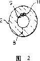
Fig. 2 schematically shows the cross-sectional view of embodiment shown in Figure 1;
Fig. 3 schematically shows the side view of shearing device of the present invention;
Fig. 4 schematically shows the side view of the optical fiber that continues according to the present invention;
Fig. 5 schematically shows the stereographic map of the optical fiber that continues according to the present invention; With
Fig. 6 schematically shows the stereographic map according to the alternative embodiment of the joint that continues of the present invention.
Embodiment
The mechanical splice joint 1 that is only illustrated to indefiniteness by Fig. 1 roughly comprises tubular body 2, alignment member 3 and two keyed engagement elements 4,5. Optical fiber 20,21 is contained in respectively in the keyed engagement element 4,5.As shown in Figure 1, covering is removed from the end sections of optical fiber.This optical fiber end meets in alignment member 3, and this alignment member is provided with the groove 6 that is used to hold and aim at the V-arrangement of optical fiber end.This groove has the part 6 ' of widening at place, the end of alignment member 3, make optical fiber in this zone crooked in case against fiber end face on keep-up pressure.
According to the present invention, the piecing devices 1 that continue are provided with the mechanism that is used to limit and keep the angular orientation of optical fiber.This mechanism comprises keyed engagement projection or the teat 7 that is arranged on the keyed engagement element 4,5, and this teat can be contained in the keyed engagement notch 8 that is arranged in the main body 2.The combination of teat 7 and notch 8 has guaranteed that keyed engagement element 4,5 only is inserted into (as shown in Figure 2) in the main body 2 with a specific angular orientation.For example should be appreciated that and optical fiber 20,21 firmly and immovably can be remained in the keyed engagement element 4,5 by the keyed engagement element is crimped onto on the optical fiber.
In case be inserted in the main body 2, the keyed engagement element of embodiment shown in Figure 1 is kept by the elasticity lock bolt, and this lock bolt tightens after the projection 10 of keyed engagement element.Lock bolt 9 can be made and be contained in the notch 11 by metal (for example tinsel) or plastics.Optical fiber end is contained in the keyed engagement element by this way, that is, when the keyed engagement element tightens, optical fiber end abut against each other and optical fiber at least one optical fiber slight curvature in a part 6 ' of widening.This guarantees the good contact between fiber end face.
As shown in Figure 1, the layout of the second keyed engagement element 5 has been rotated 180 degree with respect to the first keyed engagement element 4.This layout is all used single keyed engagement element for the both sides of these piecing devices 1 that continue, and the more important thing is, has guaranteed the correct angular orientation of fiber end face.This will describe with reference to Fig. 3 following.
Keyed engagement element 4 (also as shown in Figure 1) is attached on the optical fiber 20, and this optical fiber has the end sections 22 that covering is removed.This keyed engagement element 4 is inserted in the supporting member 29 subsequently.Because notch 8 and teat 7, keyed engagement element 4 only insert with a specific angular orientation.By using shearing device 28 known in the art to be cut off with an angle, this shearing device is for example known from International Patent Application WO 98/54608 subsequently for optical fiber end.The angled end face 24 that is obtained as Fig. 4 schematically shown in, wherein for clear, angle [alpha] is by exaggerative.
With reference to Fig. 3, keyed engagement element 4 takes off and is inserted into from supporting member 29 subsequently and continues the adapter body 2.(should be noted that the adapter body that continues can be equipped with an optical fiber in factory, also can insert two optical fiber certainly at the scene).The teat 7 of the adapter body that continues 2 and notch 8 have guaranteed that keyed engagement element 4 inserts with predetermined orientation, for example as shown in the figure with accurate identical orientation when it is cut off.
Can repeat above process for the keyed engagement element 5 that keeps optical fiber 21.As shown in Figure 1, keyed engagement element 5 is inserted in the adapter body 2 that continues with respect to keyed engagement element 4 Rotate 180 degree, and this causes fiber end face 24,25 parallel, as shown in Figure 4.When two keyed engagement elements were tightened, end face 24,25 abut against each other, and this causes having realized preferable continuing with low-down reflection loss.
In the embodiment shown in fig. 5, spring 19 is contained between keyed engagement element and the keyed engagement element retainer 18, so that biasing force is provided, guarantees the good contact of fiber end face.
In the embodiment shown in fig. 6, there is not the keyed engagement element.What replace the keyed engagement element is " quick-snap " mechanism 17, and it is generally used in the cap for brush of ball pen etc.Certainly, can envision various embodiment, wherein can obtain advantage according to angled cut-out of the present invention.
Therefore, those of ordinary skill in the art should be appreciated that the embodiment shown in the invention is not restricted to, and under the situation in not departing from the scope of the present invention, can carry out many additional and modification.
Claims (10)
1. the method for a jointed fiber, it may further comprise the steps:
First optical fiber (20) is fixed to has on the special first radial oriented keyed engagement element (4), a part of wherein said optical fiber is outstanding to surpass described keyed engagement element;
This keyed engagement element (4) is inserted in the supporting member (29), and this supporting member is only with specific radial oriented this keyed engagement element that receives;
Cut off the outshot of this optical fiber (20) on the keyed engagement element (4) that is fixed to this insertion with predetermined angle with respect to this supporting member (29), so that on the remainder of giving prominence to the optical fiber that surpasses described keyed engagement element, form the first angled fiber end face (24);
Take off this keyed engagement element from this supporting member;
This keyed engagement element is inserted in the adapter body that continues (2), and this adapter body that continues only radial orientedly receives this keyed engagement element with specific, so that the first angled fiber end face (24) has predictable orientation with respect to this adapter body that continues; And
Repeat above step for second optical fiber (21) and the second keyed engagement element (5), to form the second angled fiber end face (25), wherein the second keyed engagement element (5) need be with respect to first keyed engagement element (4) the Rotate 180 degree in insertion continues the process of adapter body (2), and this first angled fiber end face (24) and the second angled fiber end face (25) carry out resilient abutment with the orientation of almost parallel thus.
2. the method for claim 1 is characterized in that, cut this angle of this optical fiber becomes the 5-12 degree with respect to the straight line perpendicular to the longitudinal axis of each optical fiber.
3. method as claimed in claim 1 or 2 is characterized in that, the step that optical fiber (20,21) is fixed on the keyed engagement element (4,5) relates to sleeve (15) contraction that makes heat recoverable around this keyed engagement element.
4. method as claimed in claim 1 or 2 is characterized in that, the step that optical fiber (20,21) is fixed on the keyed engagement element (4,5) relates to this keyed engagement element of crimping.
5. method as claimed in claim 1 or 2 is characterized in that, described against angled fiber end face (24,25) be contained in the alignment member (3).
6. method as claimed in claim 5, it is characterized in that this alignment member (3) comprises first element (3a) and second element (3b), optical fiber is contained in therebetween, at least one element is provided with the roughly groove of V-arrangement (6), and this groove is capped when described element is drawn close.
7. method as claimed in claim 1 or 2 is characterized in that, this adapter body that continues (2) but receiving connector.
8. method as claimed in claim 1 or 2 is characterized in that, this first keyed engagement element (4) is inserted in manufacture process in this adapter body that continues (2).
9. method as claimed in claim 1 or 2 is characterized in that, this adapter body that continues (2) is provided with the lock bolt that at least one is used for flexibly tightening keyed engagement element (4,5).
10. method as claimed in claim 1 or 2 is characterized in that, optical gel is applied on this second fiber end face (25).
Applications Claiming Priority (2)
| Application Number | Priority Date | Filing Date | Title |
|---|---|---|---|
| GBGB0123830.2A GB0123830D0 (en) | 2001-10-04 | 2001-10-04 | "Method and apparatus for splicing optical fibres" |
| GB0123830.2 | 2001-10-04 |
Publications (2)
| Publication Number | Publication Date |
|---|---|
| CN1564954A CN1564954A (en) | 2005-01-12 |
| CN100347579C true CN100347579C (en) | 2007-11-07 |
Family
ID=9923228
Family Applications (1)
| Application Number | Title | Priority Date | Filing Date |
|---|---|---|---|
| CNB028197526A Expired - Fee Related CN100347579C (en) | 2001-10-04 | 2002-09-11 | Method and apparatus for splicing optical fibres |
Country Status (21)
| Country | Link |
|---|---|
| US (1) | US7014372B2 (en) |
| EP (1) | EP1433007B1 (en) |
| KR (1) | KR100913857B1 (en) |
| CN (1) | CN100347579C (en) |
| AT (1) | ATE358285T1 (en) |
| AU (1) | AU2002321651B2 (en) |
| BR (1) | BR0213032A (en) |
| CA (1) | CA2460527C (en) |
| DE (1) | DE60219183T2 (en) |
| DK (1) | DK1433007T3 (en) |
| ES (1) | ES2284906T3 (en) |
| GB (1) | GB0123830D0 (en) |
| IL (1) | IL160778A0 (en) |
| MX (1) | MXPA04003152A (en) |
| NO (1) | NO20041812L (en) |
| PL (1) | PL204576B1 (en) |
| PT (1) | PT1433007E (en) |
| RU (1) | RU2295143C2 (en) |
| TW (1) | TWI225553B (en) |
| WO (1) | WO2003029866A2 (en) |
| ZA (1) | ZA200401878B (en) |
Families Citing this family (17)
| Publication number | Priority date | Publication date | Assignee | Title |
|---|---|---|---|---|
| US7887244B2 (en) * | 2008-06-13 | 2011-02-15 | Belden Cdt (Canada) Inc. | Reversible fiber connector with mechanical splice and sliding lock |
| US8075198B2 (en) * | 2008-06-23 | 2011-12-13 | Belden Cdt (Canada) Inc. | Reversible fiber connector with mechanical sliding splice |
| WO2010020048A1 (en) * | 2008-08-19 | 2010-02-25 | Belden Cdt (Canada) Inc. | Slide actuated field installable fiber optic connector |
| US7811006B2 (en) * | 2008-09-02 | 2010-10-12 | Belden CD (Canada) Inc. | Field installable fiber optic connector and installation tool |
| WO2010092654A1 (en) * | 2009-02-12 | 2010-08-19 | 株式会社フジクラ | Optical connector |
| AU2009227906B2 (en) * | 2009-10-21 | 2015-04-02 | Tyco Electronics Services Gmbh | Apparatus for mechanically splicing optic fibres |
| US8506178B2 (en) | 2011-06-24 | 2013-08-13 | Go!Foton Holdings, Inc. | Mechanical splicer apparatus for fiber optic cables |
| US8494331B2 (en) | 2011-07-06 | 2013-07-23 | Go!Foton Holdings, Inc. | Apparatus and method for mass producing optical fiber splice-on connector subunits |
| US8506179B2 (en) | 2011-07-21 | 2013-08-13 | Go!Foton Holdings, Inc. | Deformable plastic radially symmetric mechanical splicers and connectors for optical fibers |
| US8979395B2 (en) | 2011-09-07 | 2015-03-17 | Adc Telecommunications, Inc. | Tools and methods for preparing a ferrule-less optical fiber connector |
| EP2753962A4 (en) * | 2011-09-07 | 2015-08-19 | Adc Telecommunications Inc | Optical fiber connection system |
| US8985867B2 (en) | 2011-09-07 | 2015-03-24 | Adc Telecommunications, Inc. | Optical fiber connection system |
| US8985864B2 (en) | 2011-09-07 | 2015-03-24 | Adc Telecommunications, Inc. | Optical fiber alignment device and method |
| JP6032937B2 (en) * | 2012-02-29 | 2016-11-30 | スリーエム イノベイティブ プロパティズ カンパニー | Fiber optic cable connector |
| GB2501974B (en) * | 2012-04-02 | 2016-09-07 | Oxford Fiber Ltd | Profiling of cleaved angled end faces of optical fiber(s) |
| CN102944915A (en) * | 2012-11-30 | 2013-02-27 | 清华大学 | Optical fiber connecting method |
| EP4016147A1 (en) * | 2016-03-16 | 2022-06-22 | Berk-Tek LLC | Mpo fiber optic connector with polarity reversible by a removable key |
Citations (3)
| Publication number | Priority date | Publication date | Assignee | Title |
|---|---|---|---|---|
| DE3701421A1 (en) * | 1987-01-20 | 1988-07-28 | Standard Elektrik Lorenz Ag | Optical plug-type connector |
| EP0419699A1 (en) * | 1989-09-27 | 1991-04-03 | Hewlett-Packard GmbH | Method for manufacturing an optical fibre connector |
| WO1998054608A1 (en) * | 1997-05-30 | 1998-12-03 | Oxford Fiber Optic Tools Limited | Tool for angled cleaving of optical fibers or the like |
Family Cites Families (15)
| Publication number | Priority date | Publication date | Assignee | Title |
|---|---|---|---|---|
| US4229876A (en) | 1978-08-29 | 1980-10-28 | The Deutsch Company Electronic Components Division | Optical fiber breaker and method, and combination breaker and optical connector |
| JPS5938707A (en) * | 1982-08-30 | 1984-03-02 | Fujitsu Ltd | Optical fiber connector |
| US4783137A (en) * | 1983-11-15 | 1988-11-08 | Kosman Karel J | Fiber optic coupling system |
| US4687288A (en) | 1985-07-19 | 1987-08-18 | Allied Corporation | Fiber optic connector with temperature compensating mechanism |
| US4705352A (en) | 1985-12-30 | 1987-11-10 | Amphenol Corporation | Fiber optic connector |
| US4978193A (en) | 1989-08-24 | 1990-12-18 | Raychem Corporation | Optical fiber connector which provides a high signal return loss |
| US5073240A (en) | 1990-09-21 | 1991-12-17 | General Atomics | Anhydrous electrophoretic silver coating technique |
| US5384885A (en) | 1993-10-28 | 1995-01-24 | At&T Corp. | Variable attenuation optical fiber coupling |
| US5469522A (en) * | 1993-12-02 | 1995-11-21 | Litecom, Inc. | Optical fiber splice interconnection and usage method |
| CA2110940C (en) | 1993-12-08 | 1998-08-18 | Kevin G. Caldwell | Optical fiber mechanical splice |
| DE29504071U1 (en) * | 1994-03-15 | 1995-07-20 | Minnesota Mining & Mfg | Device for separating optical fibers |
| US5590229A (en) | 1994-04-22 | 1996-12-31 | Litton Systems, Inc. | Multichannel fiber optic connector |
| US5524163A (en) * | 1994-12-29 | 1996-06-04 | Sumitomo Electric Industries, Ltd. | Apparatus for splicing optical fibers and method for the same |
| DE19639184A1 (en) * | 1996-09-24 | 1998-03-26 | Siemens Ag | Crimped connection tube for optical fibres transmission elements |
| US5862289A (en) * | 1997-02-18 | 1999-01-19 | Amphenol Corporation | Adhesiveless fiber optic connector, and an apparatus and method for terminating a fiber optic cable to an adhesiveless fiber optic connector |
-
2001
- 2001-10-04 GB GBGB0123830.2A patent/GB0123830D0/en not_active Ceased
-
2002
- 2002-08-21 TW TW091118902A patent/TWI225553B/en not_active IP Right Cessation
- 2002-09-11 EP EP02755362A patent/EP1433007B1/en not_active Expired - Lifetime
- 2002-09-11 PT PT02755362T patent/PT1433007E/en unknown
- 2002-09-11 KR KR1020047004937A patent/KR100913857B1/en not_active IP Right Cessation
- 2002-09-11 IL IL16077802A patent/IL160778A0/en unknown
- 2002-09-11 AU AU2002321651A patent/AU2002321651B2/en not_active Ceased
- 2002-09-11 RU RU2004114241/28A patent/RU2295143C2/en not_active IP Right Cessation
- 2002-09-11 US US10/490,168 patent/US7014372B2/en not_active Expired - Fee Related
- 2002-09-11 CA CA2460527A patent/CA2460527C/en not_active Expired - Fee Related
- 2002-09-11 MX MXPA04003152A patent/MXPA04003152A/en active IP Right Grant
- 2002-09-11 DK DK02755362T patent/DK1433007T3/en active
- 2002-09-11 PL PL367542A patent/PL204576B1/en not_active IP Right Cessation
- 2002-09-11 BR BR0213032-7A patent/BR0213032A/en not_active IP Right Cessation
- 2002-09-11 DE DE60219183T patent/DE60219183T2/en not_active Expired - Lifetime
- 2002-09-11 WO PCT/GB2002/004163 patent/WO2003029866A2/en active IP Right Grant
- 2002-09-11 CN CNB028197526A patent/CN100347579C/en not_active Expired - Fee Related
- 2002-09-11 ES ES02755362T patent/ES2284906T3/en not_active Expired - Lifetime
- 2002-09-11 AT AT02755362T patent/ATE358285T1/en active
-
2004
- 2004-03-08 ZA ZA200401878A patent/ZA200401878B/en unknown
- 2004-05-04 NO NO20041812A patent/NO20041812L/en not_active Application Discontinuation
Patent Citations (3)
| Publication number | Priority date | Publication date | Assignee | Title |
|---|---|---|---|---|
| DE3701421A1 (en) * | 1987-01-20 | 1988-07-28 | Standard Elektrik Lorenz Ag | Optical plug-type connector |
| EP0419699A1 (en) * | 1989-09-27 | 1991-04-03 | Hewlett-Packard GmbH | Method for manufacturing an optical fibre connector |
| WO1998054608A1 (en) * | 1997-05-30 | 1998-12-03 | Oxford Fiber Optic Tools Limited | Tool for angled cleaving of optical fibers or the like |
Also Published As
| Publication number | Publication date |
|---|---|
| MXPA04003152A (en) | 2004-07-08 |
| GB0123830D0 (en) | 2001-11-28 |
| ES2284906T3 (en) | 2007-11-16 |
| PT1433007E (en) | 2007-05-31 |
| KR100913857B1 (en) | 2009-08-26 |
| DE60219183T2 (en) | 2008-01-24 |
| ATE358285T1 (en) | 2007-04-15 |
| DK1433007T3 (en) | 2007-07-02 |
| KR20040048418A (en) | 2004-06-09 |
| WO2003029866A2 (en) | 2003-04-10 |
| WO2003029866A3 (en) | 2003-10-30 |
| CA2460527A1 (en) | 2003-04-10 |
| EP1433007B1 (en) | 2007-03-28 |
| US20050018982A1 (en) | 2005-01-27 |
| RU2295143C2 (en) | 2007-03-10 |
| DE60219183D1 (en) | 2007-05-10 |
| CA2460527C (en) | 2012-06-26 |
| CN1564954A (en) | 2005-01-12 |
| TWI225553B (en) | 2004-12-21 |
| US7014372B2 (en) | 2006-03-21 |
| AU2002321651B2 (en) | 2007-12-06 |
| EP1433007A2 (en) | 2004-06-30 |
| PL367542A1 (en) | 2005-02-21 |
| IL160778A0 (en) | 2004-08-31 |
| ZA200401878B (en) | 2005-03-08 |
| RU2004114241A (en) | 2005-02-27 |
| BR0213032A (en) | 2004-10-05 |
| PL204576B1 (en) | 2010-01-29 |
| NO20041812L (en) | 2004-05-04 |
Similar Documents
| Publication | Publication Date | Title |
|---|---|---|
| CN100347579C (en) | Method and apparatus for splicing optical fibres | |
| US6234685B1 (en) | Quick connect fiber optic connector having a deformable barrel | |
| US4684205A (en) | Fiber optic connector with compensating mechanism | |
| US4687288A (en) | Fiber optic connector with temperature compensating mechanism | |
| US5142602A (en) | Fiber optic connectors | |
| US5909528A (en) | Optical connector and assembly method thereof | |
| US9146364B2 (en) | Optical fiber connector | |
| EP1443350B1 (en) | Tunable fiber optic connector | |
| JP5106926B2 (en) | Actuating tools for fiber optic connectors | |
| TW342461B (en) | Optical fiber mechanical splice | |
| EP0244225B1 (en) | Optic fiber connector | |
| JP2007334353A (en) | Reversible fiber-optic connector | |
| US4795231A (en) | Optical fiber connector | |
| WO2014011283A2 (en) | Optical fiber connector ferrule having curved external alignment surface | |
| CN1148179A (en) | Re-enterable splicer for ribbon fiber | |
| CN1085666A (en) | Optical fiber three rod connectors that excellent anchorage clip is arranged | |
| AU2002321651A1 (en) | Method and apparatus for splicing optical fibres | |
| WO2010015813A1 (en) | An external fixation clamp | |
| CN1717562A (en) | Hydraulic hose fitting and method | |
| CN1024154C (en) | Applying pressure to abutting optical faces | |
| JPS5840515A (en) | Optical fiber connector | |
| US20220019026A1 (en) | Field assembly optical connector configured to prevent optical fiber bending |
Legal Events
| Date | Code | Title | Description |
|---|---|---|---|
| C06 | Publication | ||
| PB01 | Publication | ||
| C10 | Entry into substantive examination | ||
| SE01 | Entry into force of request for substantive examination | ||
| C14 | Grant of patent or utility model | ||
| GR01 | Patent grant | ||
| CF01 | Termination of patent right due to non-payment of annual fee | ||
| CF01 | Termination of patent right due to non-payment of annual fee |
Granted publication date: 20071107 Termination date: 20170911 |