CN100344455C - Element board for recording head, recording head and recording head control method - Google Patents
Element board for recording head, recording head and recording head control method Download PDFInfo
- Publication number
- CN100344455C CN100344455C CNB2004100968038A CN200410096803A CN100344455C CN 100344455 C CN100344455 C CN 100344455C CN B2004100968038 A CNB2004100968038 A CN B2004100968038A CN 200410096803 A CN200410096803 A CN 200410096803A CN 100344455 C CN100344455 C CN 100344455C
- Authority
- CN
- China
- Prior art keywords
- mentioned
- signal
- record
- record head
- latch cicuit
- Prior art date
- Legal status (The legal status is an assumption and is not a legal conclusion. Google has not performed a legal analysis and makes no representation as to the accuracy of the status listed.)
- Expired - Fee Related
Links
Images


Classifications
-
- B—PERFORMING OPERATIONS; TRANSPORTING
- B41—PRINTING; LINING MACHINES; TYPEWRITERS; STAMPS
- B41J—TYPEWRITERS; SELECTIVE PRINTING MECHANISMS, i.e. MECHANISMS PRINTING OTHERWISE THAN FROM A FORME; CORRECTION OF TYPOGRAPHICAL ERRORS
- B41J2/00—Typewriters or selective printing mechanisms characterised by the printing or marking process for which they are designed
- B41J2/005—Typewriters or selective printing mechanisms characterised by the printing or marking process for which they are designed characterised by bringing liquid or particles selectively into contact with a printing material
- B41J2/01—Ink jet
- B41J2/015—Ink jet characterised by the jet generation process
- B41J2/04—Ink jet characterised by the jet generation process generating single droplets or particles on demand
- B41J2/045—Ink jet characterised by the jet generation process generating single droplets or particles on demand by pressure, e.g. electromechanical transducers
- B41J2/04501—Control methods or devices therefor, e.g. driver circuits, control circuits
- B41J2/04541—Specific driving circuit
-
- B—PERFORMING OPERATIONS; TRANSPORTING
- B41—PRINTING; LINING MACHINES; TYPEWRITERS; STAMPS
- B41J—TYPEWRITERS; SELECTIVE PRINTING MECHANISMS, i.e. MECHANISMS PRINTING OTHERWISE THAN FROM A FORME; CORRECTION OF TYPOGRAPHICAL ERRORS
- B41J2/00—Typewriters or selective printing mechanisms characterised by the printing or marking process for which they are designed
- B41J2/005—Typewriters or selective printing mechanisms characterised by the printing or marking process for which they are designed characterised by bringing liquid or particles selectively into contact with a printing material
- B41J2/01—Ink jet
- B41J2/015—Ink jet characterised by the jet generation process
- B41J2/04—Ink jet characterised by the jet generation process generating single droplets or particles on demand
- B41J2/045—Ink jet characterised by the jet generation process generating single droplets or particles on demand by pressure, e.g. electromechanical transducers
- B41J2/04501—Control methods or devices therefor, e.g. driver circuits, control circuits
- B41J2/0455—Details of switching sections of circuit, e.g. transistors
-
- B—PERFORMING OPERATIONS; TRANSPORTING
- B41—PRINTING; LINING MACHINES; TYPEWRITERS; STAMPS
- B41J—TYPEWRITERS; SELECTIVE PRINTING MECHANISMS, i.e. MECHANISMS PRINTING OTHERWISE THAN FROM A FORME; CORRECTION OF TYPOGRAPHICAL ERRORS
- B41J2/00—Typewriters or selective printing mechanisms characterised by the printing or marking process for which they are designed
- B41J2/005—Typewriters or selective printing mechanisms characterised by the printing or marking process for which they are designed characterised by bringing liquid or particles selectively into contact with a printing material
- B41J2/01—Ink jet
- B41J2/015—Ink jet characterised by the jet generation process
- B41J2/04—Ink jet characterised by the jet generation process generating single droplets or particles on demand
- B41J2/045—Ink jet characterised by the jet generation process generating single droplets or particles on demand by pressure, e.g. electromechanical transducers
- B41J2/04501—Control methods or devices therefor, e.g. driver circuits, control circuits
- B41J2/0458—Control methods or devices therefor, e.g. driver circuits, control circuits controlling heads based on heating elements forming bubbles
-
- B—PERFORMING OPERATIONS; TRANSPORTING
- B41—PRINTING; LINING MACHINES; TYPEWRITERS; STAMPS
- B41J—TYPEWRITERS; SELECTIVE PRINTING MECHANISMS, i.e. MECHANISMS PRINTING OTHERWISE THAN FROM A FORME; CORRECTION OF TYPOGRAPHICAL ERRORS
- B41J2/00—Typewriters or selective printing mechanisms characterised by the printing or marking process for which they are designed
- B41J2/005—Typewriters or selective printing mechanisms characterised by the printing or marking process for which they are designed characterised by bringing liquid or particles selectively into contact with a printing material
- B41J2/01—Ink jet
- B41J2/015—Ink jet characterised by the jet generation process
- B41J2/04—Ink jet characterised by the jet generation process generating single droplets or particles on demand
- B41J2/045—Ink jet characterised by the jet generation process generating single droplets or particles on demand by pressure, e.g. electromechanical transducers
- B41J2/05—Ink jet characterised by the jet generation process generating single droplets or particles on demand by pressure, e.g. electromechanical transducers produced by the application of heat
-
- B—PERFORMING OPERATIONS; TRANSPORTING
- B41—PRINTING; LINING MACHINES; TYPEWRITERS; STAMPS
- B41J—TYPEWRITERS; SELECTIVE PRINTING MECHANISMS, i.e. MECHANISMS PRINTING OTHERWISE THAN FROM A FORME; CORRECTION OF TYPOGRAPHICAL ERRORS
- B41J2/00—Typewriters or selective printing mechanisms characterised by the printing or marking process for which they are designed
- B41J2/22—Typewriters or selective printing mechanisms characterised by the printing or marking process for which they are designed characterised by selective application of impact or pressure on a printing material or impression-transfer material
- B41J2/23—Typewriters or selective printing mechanisms characterised by the printing or marking process for which they are designed characterised by selective application of impact or pressure on a printing material or impression-transfer material using print wires
- B41J2/235—Print head assemblies
Abstract
In a printhead having a plurality of printing elements, a shift register which serially receives printing data corresponding to the number of printing elements, a latch which latches the printing data input to the shift register, and a driving circuit which selectively drives the printing elements in accordance with the printing data latched by the latch and a signal representing a driving period, the latch state of the latch is controlled by the signal representing the driving period. The signal representing the driving period and a signal for controlling the latch state of the latch are commonly used to decrease the number of input terminals of the printhead.
Description
Technical field
The present invention relates to the control method of element board for printhead, record head and record head, in more detail, relate to and have a plurality of recording elements,, drive the record head that above-mentioned recording element writes down and the control method of this record head according to the record data of serial input.
In addition, the present invention is except that the general printing equipment that uses such record head to write down, can also be applicable to devices such as duplicator, facsimile machine, word processor, and then also be applicable to the industrial tape deck that carries out the combined type combination with various treating apparatus.
Background technology
For example as information output apparatus such as word processor, personal computer, facsimile machines, be extensive use of the tape deck that information such as desirable literal or image is recorded on the laminar recording mediums such as paper or film.
Recording mode as tape deck, known have various modes, but, in recent years, owing to can carry out recording mediums such as paper noncontact record, easily colorize, be rich in reason such as quietness, ink-jetting style is particularly noticeable, as its structure, because according to desirable recorded information, along the direction that the throughput direction with recording medium such as paper intersects, the record head of discharging China ink is come and gone scan the cheap and easy miniaturization of the serial recording mode that writes down generally to be widely used.
Figure 11 is the block diagram of typical circuit structure of representing the record head of ink-jetting style in the past.
Among Figure 11, the 101st, be used to produce the electrothermal conversioning element (heater) of heat energy, the 102nd, be used for providing the power tube of desirable electric current to heater, the 103rd, according to the image information that will write down, temporary transient storage determines whether to discharge from the nozzle of record head the shift register of the record data DATA of China ink, 104 are arranged on being used on the shift register imports the transmission clock input terminal of transmission clock signal CLK, the 105th, be used for record data DATA serial is input to the record data input terminal of shift register, the 106th, be used to keep be stored in the latch cicuit of the record data of shift register, the 107th, the latch signal input terminal of input and latch signal LT, this latch signal is used to control latching regularly of latch cicuit 106, the 108th, be used for applying predetermined voltage (VH) and the power line of electric current being provided to heater, the 109th, become power supply and the GND line of the benchmark of the voltage that applied.
Figure 12 is the sequential chart that is used to drive the various signals of record head shown in Figure 11.201 expression transmission clock CLK, 202 expression record data DATA, 203 expression latch signals (LT), the hot enable signal HE of 204 expressions.
To 104 input transmission clock (CLK) pulses 201 of transmission clock input terminal.Then, carry the record data (DATA) 202 of each heater on/off of terminal 105 serials input expression, make to the two edges of the transmission of the record data of shift register 103 and transmission clock 201 synchronous from data., after data are sent to shift register 103, be input to the timing of latch input terminal 107 here, the record data that latch cicuit 106 keeps corresponding to each heater according to latch signal (LT) 203.
After this, apply hot enable signal (HE) 204 with suitable timing.Become time of connection (in this example for low level) according to hot enable signal, power tube 102 and heater 101 are switched on, and discharge China ink according to record data.The also quantity (connecting figure place simultaneously) of the temperature of with good grounds record head and the heater that drives simultaneously changes the situation of the time that drives heater as required.
In Figure 12, according to hot enable signal 204, before driving heater, apply prepulse 205, the technology of No. 6139125 (Japanese Patent Application Publication spy opens flat 5-31906 communique) middle record that this is based on United States Patent (USP), be intended to by prepulse 205 is provided, make record head keep high temperature, seek the stable of black discharge rate.In addition, because the application time of prepulse is very of short duration, so do not discharge China ink.
In addition, in United States Patent (USP) No. 6139125 (Japanese Patent Application Publication spy opens flat 9-327914 communique), record such structure, promptly, for the quantity that reduces input terminal and improve reliability, the signal of a plurality of holding wires inputs is decoded and produced clock selection signal.
In recent years, ink-jet printer multicolor, high speed, further develop to high picture elementization, exist the tendency that the record data amount increases.Therefore the quantity that exists the required signal of activation record head increases the tendency that the input subnumber also increases.The increase of input subnumber causes the increase of reduction, chip (chip) area of connection reliability and the increase of the component costs that therefore causes etc.
Because the expense increase of record head is related to the cost of device integral body and the rising of running cost, therefore wish to reduce the input subnumber.
Summary of the invention
The objective of the invention is to, the record head element body that has reduced the input subnumber is provided.
Other purposes of the present invention are, a kind of record head that reduces the input subnumber is provided.
Other purposes of the present invention are, a kind of control method of record head of the input subnumber that can reduce record head is provided.
For achieving the above object, element board for printhead as a kind of form of the present invention, have a plurality of recording elements, according to record data with the serial mode input, the activation record element carries out record, and described element board for printhead comprises: the shift register of the record data that receive recording element quantity corresponding with serial mode; Keep being input to the latch cicuit of the record data in the shift register; And, optionally drive the drive circuit of each recording element according to the signal during remaining on the record data in the latch cicuit and representing driving; Wherein, as the signal of the hold mode of controlling latch cicuit, use the signal during expression drives.
For achieving the above object, has the described element board for printhead of above-mentioned form as the record head of another form of the present invention.
For achieving the above object, as the control method of the record head of another form of the present invention, this record head has a plurality of recording elements; The shift register of the record data that receive recording element quantity corresponding with serial mode; Maintenance is input to the latch cicuit of the record data of shift register; And according to the signal during record data that remain on latch cicuit and the expression driving, optionally drive the drive circuit of each recording element, the signal during the control method of this record head drives according to expression, the hold mode of control latch cicuit.
That is to say, in the present invention, in record head, according to the signal during the expression driving, the hold mode of control latch cicuit, this record head has: a plurality of recording elements; The shift register of the record data that receive recording element quantity corresponding with serial mode; Maintenance is input to the latch cicuit of the record data of shift register; And, optionally drive the drive circuit of each recording element according to the signal during remaining on the record data in the latch cicuit and representing driving.
Like this, by the signal of the signal during the shared expression driving and the hold mode of control latch cicuit, reduce the input subnumber of record head.
In addition, can follow the minimizing of input subnumber, dwindle the area of integrated circuit, can reduce the cost of record head thus.
Signal during expression drives is a pulse signal, and drive circuit is according to the level of this pulse signal, the activation record element, and latch cicuit can also be according to the edge of pulse signal, the data of holding the record.
Can also possess deferred mount, postpone the signal during expression drives, make that to be input to timing latch cicuit and drive circuit, the signal of expression during driving different.
Signal during expression drives can comprise 2 pulse signals at least.
Can also possess signaling conversion circuit, convert at least 2 pulse signals to single pulse signal, be used as the signal of the hold mode of control latch cicuit through the pulse signal of this signaling conversion circuit conversion.
As the reset signal of signaling conversion circuit, can also use regulation to be input to the clock signal of the timing of shift register record data.
As record head, be to discharge the ink jet print head that China ink writes down, in more detail, be to be applicable to the record head that utilizes heat energy and discharge China ink, in addition, recording element is made of electrothermal conversioning element.。
A plurality of recording elements, shift register, latch cicuit and drive circuit can also be fabricated on the identity element matrix.
In addition, the present invention also can be applicable to the tape deck, the record head as described above that use above-mentioned record head to write down, have the record head print cartridge of print cartridge of the China ink that is used to keep to offer this record head and the control method of the record head corresponding with above-mentioned record head.
Other features and advantages of the present invention can obtain clearly by the following explanation of carrying out with reference to accompanying drawing.In these accompanying drawings, identical label is represented identical or similar part.
Description of drawings
Accompanying drawing is included in the specification and constitutes the part of specification, is used to illustrate embodiments of the invention, and is used from explanation principle of the present invention with specification one.
Fig. 1 is the block diagram of the 1st embodiment of the circuit structure of expression record head.
Fig. 2 A and Fig. 2 B are the sequential charts of the state of each signal in the circuit of presentation graphs 1.
Fig. 3 is the block diagram of the 2nd embodiment of the circuit structure of expression record head.
Fig. 4 A and Fig. 4 B are the sequential charts of the state of each signal in the circuit of presentation graphs 3.
Fig. 5 is the block diagram of the circuit structure of expression record head.
Fig. 6 is the outward appearance oblique view of the structural outline of the ink-jet recording apparatus that write down by record head of expression.
Fig. 7 is the block diagram of the control structure of expression tape deck shown in Figure 6.
Fig. 8 is the exploded perspective view of the frame for movement of expression record head.
Fig. 9 is the 1st figure of the structure of expression record head print cartridge.
Figure 10 is the 2nd figure of the structure of expression record head print cartridge.
Figure 11 is a block diagram of representing the circuit structure of record head in the past.
Figure 12 is the sequential chart of state of each signal in the circuit of expression Figure 11.
The specific embodiment
With reference to the accompanying drawings the preferred embodiments of the present invention are described in detail.Note that the composed component described in following examples only is an example, does not plan to limit scope of the present invention.
In this manual, " record " not only finger-type becomes such as significant information such as character, diagrams, also be included in information such as forming image, portrait, pattern on the recording medium widely, no matter and whether the information that forms is meaningful, or whether the information that forms is visual, so that people can from perception visually it, or handle print media.
" recording medium " can be any medium that absorbs China ink, and for example cloth, plastic sheeting, metallic plate, glass, pottery, timber and leather can also be the paper that uses in general printing equipment.
" China ink " (hereinafter being also referred to as " liquid ") should similarly be carried out the explanation of broad sense with the definition of above-mentioned " record ".That is to say that China ink is to be applied to the liquid on the recording medium and to be used to form image, portrait and pattern, handle recording medium, perhaps handle China ink (colouring agent in the China ink that is applied to recording medium is solidified or do not dissolve).
Need not superfluous words, " nozzle " should be interpreted as: outlet, any combination that is communicated to the passage of outlet and is used to discharge the energy production part of China ink.
Substrate (hereinafter being also referred to as " element body ") not only comprises the substrate of being made by silicon semiconductor, also comprises the substrate of load-carrying unit and metal wire.
In the following description, " on substrate " means not only and comprises " on substrate ", also comprise the meaning of " on the surface of substrate " and " in the substrate surperficial near it ".In the present invention, " built-in " do not represent the simple layout of resolution element on substrate, but representative is by semiconductor circuit manufacturing process, the integral body formation/manufacturing of each element on substrate.
At first, as the ink-jet recording apparatus that uses ink jet print head of the present invention to write down, be that example describes with the printer.
(explanation of ink-jet recording apparatus)
Fig. 6 is the outward appearance oblique view of summary of the structure of the ink-jet recording apparatus that write down by record head of the present invention of expression.
As shown in Figure 6, ink-jet recording apparatus (hereinafter referred to as tape deck) is according to ink-jetting style, by connecting gear 4 driving force that balladeur train motor M 1 produces is sent to balladeur train 2, balladeur train 2 is moved back and forth along the arrow A direction, and this balladeur train 2 has been installed the record head 3 of discharging the black line item of going forward side by side, and also for example passes through paper-feeding mechanism 5, the recording medium P of supply record-paper etc., and be transported to record position, in this record position, carry out record by discharging China ink to recording medium P from record head 3.
In addition,, make balladeur train 2 move to the position of recovery device 10, carry out the discharge recovery of record head 3 discontinuously and handle for the state with record head 3 maintains kilter.
On the balladeur train 2 of tape deck, record head 3 has been installed not only, the print cartridge 6 that the China ink that provides to record head 3 is provided also has been installed.Print cartridge 6 can be with respect to balladeur train 2 disassembled and assembled freelies.
Tape deck shown in Figure 6 can carry out colored record, has therefore installed on balladeur train 2 and has received and kept pinkish red (M), blue or green (C), yellow (Y), 4 black print cartridges of black (K) respectively.These 4 print cartridges can be distinguished dismounting independently.
Balladeur train 2 carries out appropriate contacting with the faying face of record head 3 these two parts, can keep desirable electrical connection.Record head 3 applies electric energy according to tracer signal, optionally discharges China ink from a plurality of outlets and carries out record.Particularly, the record head 3 of this embodiment has adopted and has utilized heat energy to discharge the ink-jetting style of China ink, for producing heat energy, has electrothermal conversion body, after the electric energy that this electrothermal conversion body applies is converted into heat energy, this heat energy is provided and produces film boiling to China ink, utilize the growth, contraction of the bubble that film boiling produces and the pressure that produces changes, China ink is discharged from outlet.This electrothermal conversion body and each outlet design accordingly, according to tracer signal, apply pulse voltage to electrothermal conversion body, discharge China ink from the outlet of correspondence thus.
As shown in Figure 6, balladeur train 2 is connected with the part of the rotating band 7 of the connecting gear 4 of the driving force that transmits balladeur train motor M 1, along the axis of guide 13 by the support of leading of arrow A direction with moving freely.So balladeur train 2 moves back and forth along the axis of guide 13 by the just commentaries on classics and the counter-rotating of balladeur train motor M 1.In addition, the scale 8 that has the absolute position of moving direction (arrow A direction) the expression balladeur train 2 that is used for along balladeur train 2.In this embodiment, scale 8 is rules of having printed black bar on transparent PET film by required interval, and the one head is fixed on the frame 9, and the other end is supported by leaf spring (not shown).
In addition, on tape deck, relative with the discharge actinal surface of the outlet that has formed record head 3, be provided with platen (not shown), utilize the driving force of balladeur train motor M 1, move back and forth the balladeur train 2 that record head 3 has been installed, also black by provide tracer signal also to discharge to record head 3, thus the enterprising line item of whole width of the recording medium P that on platen, is carried.
And then, in Fig. 6, the 14th, be the conveying roller of conveying recording medium P by 2 drivings of conveying motor M, the 15th, the pinch roll that recording medium P is contacted with spring with conveying roller 14, the 16th, can support the pinch roll support of pinch roll 15 with rotating freely, the 17th, be fixed on the conveying roller gear of an end of conveying roller 14.And, drive conveying roller 14 by means of the rotation of carrying motor M 2, wherein, the rotation of this conveying motor M 2 is sent to conveying roller gear 17 via idler gear (not shown).
And then, the 20th, be used for being discharged to the outer distributing roller of tape deck with forming record images medium P with record head 3, carry the rotation of motor M 2 to drive by transmitting.In addition, distributing roller 20 contacts with air roll (not shown) with spring (not shown) butt recording medium P.The 22nd, can support the platen support of air roll with rotating freely.
And then, as shown in Figure 6, on tape deck, dispose recovery device 10, the desired position of the reciprocating motion scope that this recovery device is used the bad operation of recording that returns to the balladeur train 2 that record head 3 has been installed of the discharge of record head 3 outer (posting field is outer) (for example, corresponding position) with the origin-location.
In addition, when non-operation of recording etc., the discharge actinal surface by 11 pairs of record heads 3 of cover pressing mechanism carries out gland, can protect record head 3, can also prevent the evaporation and the drying of China ink.On the other hand, Wiping mechanism 12 be configured in cover pressing mechanism 11 near, paying ink droplet with wiping at the discharge actinal surface of record head 3.
Utilize cover pressing mechanism 11 and Wiping mechanism 12, can keep the China ink of normal record head 3 to discharge state.
(control structure of ink-jet recording apparatus)
Fig. 7 is the block diagram of the control structure of expression tape deck shown in Figure 6.
As shown in Figure 7, controller 900 is made of following structure: MPU901; Store the ROM902 of program, needed table and other fixed datas corresponding with aftermentioned control sequence; The specific use integrated circuit (ASIC) 903 of the control signal of the control usefulness of control, the control of carrying motor M 2 and the record head 3 of generation balladeur train motor M 1; Be provided with the RAM904 in the spreading area of record data and the operation usefulness zone of program execution usefulness etc.; Interconnect MPU901, ASIC903, RAM904 and receive and dispatch the system bus 905 of data; And input offers data signal the A/D converter 906 of MPU901 etc. from the analog signal of following sensor groups and carry out the A/D conversion.Make the signal of mechanism of the electrothermal conversion body heating of record head as appointment, slave controller 900 supplies to record head to the signal that dual-purpose heat described later enables (HE) signal and latch signal (LT).
In Fig. 7,910 for record data provide the computer (perhaps reading the reader of usefulness or digital camera etc. for image) in source, is generically and collectively referred to as main device.Between main device 910 and the tape deck, via interface (I/F) 911 transmitting-receiving record data, order, status signal etc.
The 920th, switches set is by power switch 921, the switch that is used to instruct the recovery switch 923 etc. of starting of the print switch 922 of printing beginning, processing (recovering to handle) that indication maintains the black discharging performance of record head 3 kilter to accept operator's instruction input constituted.The 930th, the sensor groups that the checkout gear state that is made of position sensor 931, temperature sensor 932 etc. is used, this position sensor 931 is the sensors that detect photoelectrical coupler that original position (home position) h uses etc., and this temperature sensor 932 is the sensors that are arranged on the suitable position of tape deck for the testing environment temperature.
The 940th, the balladeur train motor driver of driving balladeur train motor M 1, this balladeur train motor M l is used to make balladeur train 2 along arrow A direction shuttle-scanning, and the 942nd, drive the conveying motor driver of carrying motor M 2, this conveying motor M 2 is used for conveying recording medium P.
ASIC903 when carrying out writing scan by record head 3, the storage area of directly visiting RAM902, and transmit the driving data (DATA) of recording element (discharge heater) to record head.
(frame for movement of record head)
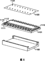
Fig. 8 is the exploded perspective view of the frame for movement of the ink jet print head 3 that uses in the above-mentioned tape deck of expression.
The central authorities of Fig. 8 have represented to make integratedly the element body 1101 of following circuit structure on the substrate of silicon etc., on this element body, formed the heating resistor 1112 as the electrothermal conversioning element that constitutes recording element, the both sides towards the substrate that surrounds this resistive element have formed stream 1111.As the parts that constitute this stream, can use resin such as dry film or SiN etc.
The orifice plate (orifice plate) 1102 of element body top expression on the position of heating resistor 1112 relatively, has a plurality of outlets 1121, and with the components bonding that constitutes stream.
The wall components 1103 of element body below expression is the parts that are configured for providing the shared liquid chamber of China ink, provides China ink from this shared liquid chamber to each stream around the end of this device substrate 1101.
In the both sides of element body 1101, be provided with the splicing ear 1113 that is used for receiving data and signal from the tape deck main body.
(circuit structure of record head)
Below, the embodiment of circuit structure of the ink jet print head of said structure is described.In the following description, about Figure 11 and Figure 12, represent with identical label with the routine in the past identical part that has illustrated, and omit detailed explanation.
[the 1st embodiment]
Fig. 1 is the block diagram of circuit structure of the 1st embodiment of expression ink jet print head of the present invention.Fig. 2 A and Fig. 2 B are the sequential charts of state of each signal of the circuit of presentation graphs 1.
Here, the cycle and the timing of each signal are described, the cycle of clock signal is 6MHz~12MHz, discharging frequency approximately is 15kHz, thereby the cycle of thermal signal is 4 μ s, from the trailing edge of prepulse 401 till the rising edge during be 0.2 μ s~0.6 μ s, from the trailing edge of main pulse 406 till the rising edge during be 0.6 μ s~1.2 μ s, these two interpulse dwell times are 0.2 μ s~1.0 μ s, pulse width changes according to the soaking condition of record head.
In Fig. 1, the 301st, as the input terminal that is also used as the input HE+LT signal of hot enable signal and latch signal, the 302nd, delay circuit, the 304th, T-circuits for triggering.In the present invention, the trailing edge of HE+LT signal or rising edge are as the edge-triggered of latch cicuit.In the present embodiment, the trailing edge of the prepulse of hot enable signal is as the edge-triggered of latch cicuit 106.As the example of delay circuit 302, enumerated the structure that a plurality of converters are connected in series.
In Fig. 2 A, the prepulse of HE+LT signals of 401 expressions is owing to also serve as the task of the triggering of latch cicuit 106, so that the timing that applies becomes is particularly important.The triggering of latch cicuit 106 must be after DATA402 be input to shift register 103 fully, and next DATA402 ' is input in shift register 103 timing before and applies.That is to say that applying of prepulse 401 regularly is to transmit between 402 ' in a previous DATA transmission 402 and a back DATA, therefore must set certain time interval during two DATA transmit.
When the HE+LT signal of importing Fig. 2 A to shown in Figure 1 301,105 and 104 input terminal respectively, DATA and CLK, at first the record data 402 of DATA synchronously are input to shift register 103 with two edges of clock CLK.
Secondly, with reference to the state that triggers because of the HE+LT signal in Fig. 2 B explanation latch cicuit 106.Finish and through after the enough time signal 403 of input counter-rotating HE+LT signal in the T-circuits for triggering 304 in the transmission of the record data 402 of DATA.Because T-circuits for triggering 304 are the rising edge counter-rotating output signals at input signal, so after signal 403 converts 404 to, be input to latch cicuit 106.At latch cicuit 106, owing to trigger, on the result, be to trigger with the timing identical with the trailing edge of the prepulse signal of HE+LT signal at the rising edge 405 of signal 404.After determining to make the record data 402 that remain in the shift register 103 remain on latch cicuit 106 because of this triggering, the hot enable signal that has passed through delay circuit 302 is delayed and is input to AND circuit 303.
Be set at the time delay of this delay circuit 302 to be longer than and be imported into the 106 back times that are determined to the maintenance of data of latch cicuit from triggering.Delay circuit 302 is designed to carry out reliably the record according to the record data that kept.Suppose not have delay circuit 302, then owing to hot enable signal can generate when latch cicuit 106 is determined generate simultaneously when record data keep or driven heater before this, so might carry out record according to undetermined mistake (instability) record data.To this, be provided with delay circuit 302 in the present embodiment, after the data that will write down remain on latch cicuit 106 reliably, just drive heater through after the certain hour, thereby can carry out record reliably based on correct record data.
In addition, in the present embodiment, with the reset signal of CLK signal as T-circuits for triggering 304.Thus, when the CLK signal is high level, just import reset signal continuously to T-circuits for triggering 304.Therefore, shown in Fig. 2 B, become following structure, i.e. reset signal (CLK signal) repeatedly input before prepulse, before the input of prepulse signal, the output of T-circuits for triggering 304 becomes low level reliably, has prevented the circuit maloperation.Thus, the triggering of latch cicuit 106 is all the time in the timing shown in 405, that is to say that the timing at the trailing edge of the prepulse signal 401 of HE+LT signal takes place reliably.By latching reliably, can guarantee fully to carry out more reliable record from keeping the time of logic (data of input) till the driving heater in this timing.
In addition, can expect to reduce the raising of the reliability cause, can expect because of having removed the rising that latch signal causes frequency by number of signals.In other words, because define latch signal, hot enable signal and regularly (following time delay) simultaneously, so the vacant part between can undesired signal when externally generating signal can shorten this part cycle.
In addition, the circuit of present embodiment can be the situation of single pulse signal corresponding to hot enable signal also.After pulse was input to HE+LT terminal 301, the output of T-circuits for triggering 304 became high level, but because of the input of reset signal (CLK) descends, became low level in the time of till the next pulse input.Therefore, in the circuit of present embodiment, can be any one of pulse or dipulse corresponding to the form of hot enable signal.
In addition, in the present embodiment, the chromacoder as obtain the triggering of latch cicuit from the HE+LT signal has used the T-circuits for triggering, still, as chromacoder, also can use circuits for triggering circuit in addition.
Equally, the deferred mount as inhibit signal has used delay circuit, still, also can obtain by the circuit beyond the delay circuit postponing.It for example also can be delay that utilizes wiring route etc.In addition, for example also can use the delay circuit of the such structure of a plurality of converters that has been connected in series.
[variation of the 1st embodiment]
About Fig. 2 A, as illustrating, the timing of the prepulse 401 of HE+LT signal and the trailing edge 406 of main pulse must be set between DATA signal 402 and the 402', but, between DATA402 and the prepulse 401, the trailing edge 406 of main pulse and DATA402 ' if beginning regularly between these two intervals can guarantee that time enough stablizes the action of each several part, also can not use T-circuits for triggering shown in Figure 1 304 signaling conversion circuits such as grade.
Fig. 5 is the block diagram that can use in the variation that satisfies circuit under the situation of such condition, the expression ink jet print head.To the input of the circuit of Fig. 5 during with identical signal shown in Fig. 2 A, according to the trailing edge of prepulse 401 and trailing edge 406 these 2 timings of main pulse, come latch cicuit 106 is triggered, because in these 2 timings, the data that remain on latch cicuit 106 are identical, so do not have problems on driving.
In addition, when the input signal shown in Fig. 2 A satisfies condition same as described above, also can not use delay circuit 302 and the T-circuits for triggering 304 of Fig. 1, and the circuit of ink jet print head is made as shown in Figure 3 circuit.In addition, when using circuit shown in Figure 3, the such function of preheating of usefulness is stablized in the discharge that prepulse 401 is not finished in the past, and only is used for the triggering of latch cicuit 106.
[the 2nd embodiment]
Below, the 2nd embodiment of the circuit structure of ink jet print head of the present invention is described.In the following description, the part identical with above-mentioned the 1st embodiment omitted explanation, and only the characteristic with the 2nd embodiment is that the center describes.
The 1st embodiment is following structure: as the HE+LT signal, imported the hot enable signal of dipulse, the rising edge that uses the prepulse signal is as the triggering to latch cicuit; In the 2nd embodiment, as the HE+LT signal, the hot enable signal of input pulse, the rising edge of use prepulse signal is as the triggering to latch cicuit.
Fig. 4 A is the sequential chart of the state of expression each signal relevant with present embodiment.
In Fig. 4 A, the timing of the rising edge 601 of the pulse of HE+LT signal is located between DATA signal 602 and 603, and this regularly has time enough to set at interval for guaranteeing between DATA602 and 603 these two sides.
In the past, in routine and above-mentioned the 1st embodiment, the width of thermal pulse (heat pulse) was adjusted by the rising edge position of moving hot enable signal.But because in the present embodiment, the rising edge of HE+LT signal (hot enable signal) is as the edge-triggered of latch cicuit, so do not wish to adjust the position of rising edge.Therefore in the present embodiment, the position of the rising edge 601 by the stationary heat pulse is adjusted the position of the trailing edge 604 (regularly) of thermal pulse and is adjusted pulse width.
If use the input signal shown in Fig. 4 A, then in the circuit of ink jet print head, delay circuit 302 and signaling conversion circuit (T-circuits for triggering 304) needn't be set as the 1st embodiment, just can access simple circuit, this simple circuit has only removed input terminal from as shown in Figure 3 circuit in the past.
[variation of the 2nd embodiment]
More than illustrated at the hot enable signal that uses pulse during as the HE+LT signal, with the rising edge of pulse example as the triggering of latch cicuit, still, also can be with the triggering of the trailing edge of pulse as latch cicuit.
Fig. 4 B is the sequential chart that is illustrated in the state of each input signal in this case.Among Fig. 4 B, the timing of the trailing edge 605 of HE+LT signal is located between DATA signal 606 and 607, and this regularly is for guaranteeing that the time enough between DATA606 and 607 these two sides sets at interval.
When using input signal such shown in Fig. 4 B, the circuit from Fig. 1 that the circuit of ink jet print head can be made as shown in Figure 5 removes T-circuits for triggering 304, only comprises the circuit of delay circuit 302.
In the 2nd embodiment and the variation, deferred mount is not limited to delay circuit, for example also can obtain postponing by wiring route.
In addition, preferably the foregoing description structure fabrication described, that constitute by the equivalent circuit of Fig. 1, Fig. 3, Fig. 5 to identical matrix.In this case, the input subnumber of record head reduces, and improves with the reliability that is connected of device itself.In addition, follow the minimizing of input subnumber can reduce assembly area (matrix area), can reduce the cost of record head thus.
(record head print cartridge)
The present invention also is applicable to the record head print cartridge that has above-mentioned record head and be used to keep provide to this record head the print cartridge of China ink.The form of such record head print cartridge can be the structure with the print cartridge one, perhaps can with any one of print cartridge separated structures.
Fig. 9 is the outward appearance oblique view of structure of the record head print cartridge IJC of expression print cartridge and record head integrative-structure.In record head print cartridge IJC inside, on the position of boundary line K shown in Figure 9, print cartridge IT and record head IJH are what to separate, but can not individually exchange.When record head print cartridge IJC is installed in balladeur train HC, be provided with the electrode (not shown) that is used to receive the signal of telecommunication that provides from balladeur train HC one side, according to this signal of telecommunication, activation record head IJH and discharge China ink as described above.
In Fig. 9, the 500th, black outlet row have black nozzles row and color nozzle row.In addition, be provided with fibrous or cavernous black absorber in order to keep China ink at print cartridge IT.
Figure 10 is the outward appearance oblique view of the structure of the record head print cartridge that constitutes separably of expression print cartridge and record head.Record head print cartridge H1000 has the print cartridge H1900 of storage China ink, and according to recorded information, the record head H1001 that the China ink that this print cartridge H1900 is provided is discharged from nozzle becomes and adopted the structure that can carry out the so-called print cartridge mode of dismounting with respect to balladeur train.
Among the record head print cartridge H1000 herein, colored record for the high picture element that can carry out photo one class, as print cartridge, black, light greenish blue, light magenta, green grass or young crops, magenta and yellow independently print cartridge of all kinds have for example been prepared, as shown in the figure, with respect to record head H1001, each print cartridge detachable.
[other embodiments]
In the above-mentioned embodiment, as record head of the present invention, in order to producing hot ink jet print head of discharging China ink with electrothermal conversion body is that example is illustrated, so long as latch the structure of the record data of serial input, the present invention also can be applicable to the record head of other modes.
As the tape deck that uses record head of the present invention, can be on the crossing direction of the balladeur train that record head is installed and the throughput direction of recording medium, scan the serial type of the line item of going forward side by side, also can be record head, make recording medium move the complete capable type of the line item of going forward side by side with respect to record head with length corresponding with the dominant record width of recording medium.
The quantity that possesses the record head of tape deck, can be made as and the corresponding quantity of kind that writes down employed China ink (recording agent), by using a plurality of record heads, can use many Grey Scale Recordings of monochromatic deep or light China ink (recording agent) or use the full color record of polychrome China ink such as CMYK.
In addition, the present invention not only can be applicable to record head and to the method for communicating signals of record head, also can be applicable to the device (printer, facsimile machine, duplicator etc.) that the service recorder head writes down, and then can also be applicable to the system of main equipment with such device and computer etc.
Under the premise without departing from the spirit and scope of the present invention, many visibly different embodiments can be arranged, therefore, can be understood as, the invention is not restricted to the above-mentioned specific embodiment, but limit with following claim.
Claims (13)
1. an element board for printhead has a plurality of recording elements, and the record data according to the serial mode input drive above-mentioned recording element and carry out record, it is characterized in that,
Described element board for printhead comprises:
Shift register receives the record data corresponding with the quantity of above-mentioned recording element with serial mode;
Latch cicuit, maintenance is imported into the record data of above-mentioned shift register; And
Drive circuit, the signal according to during record data that are maintained at above-mentioned latch cicuit and the expression driving optionally drives each recording element;
Wherein, as the signal of the hold mode of controlling above-mentioned latch cicuit, the signal during the above-mentioned driving of use expression.
2. element board for printhead according to claim 1 is characterized in that:
Represent that the signal during the above-mentioned driving is a pulse signal; Above-mentioned drive circuit drives above-mentioned recording element according to the level of this pulse signal; Above-mentioned latch cicuit keeps above-mentioned record data according to the edge of above-mentioned pulse signal.
3. element board for printhead according to claim 1 is characterized in that:
Also possess deferred mount, postpone the signal during the above-mentioned driving of expression, make that the timing that is imported into signal above-mentioned latch cicuit and above-mentioned drive circuit, during the above-mentioned driving of expression is different.
4. element board for printhead according to claim 1 is characterized in that:
Represent the signal during the above-mentioned driving, comprise 2 pulse signals at least.
5. element board for printhead according to claim 4 is characterized in that:
Also possess signaling conversion circuit, convert above-mentioned at least 2 pulse signals to single pulse signal;
Be used as the signal of the hold mode of the above-mentioned latch cicuit of control through the pulse signal of this signaling conversion circuit conversion.
6. element board for printhead according to claim 5 is characterized in that:
As the reset signal of above-mentioned signaling conversion circuit, use regulation record data to be input to the clock signal of the timing of above-mentioned shift register.
7. a record head has the described element board for printhead of claim 1.
8. record head according to claim 7 is characterized in that:
Above-mentioned record head is to discharge the ink jet print head that China ink writes down.
9. record head according to claim 7 is characterized in that:
Above-mentioned record head is to utilize heat energy to discharge the record head of China ink, and above-mentioned recording element is made of electrothermal conversioning element.
10. record head print cartridge has the described record head of claim 7 and is used to keep be provided for the print cartridge of the China ink of this record head.
11. a tape deck uses the described record head of claim 7 to carry out record.
12. the control method of a record head, this record head has: a plurality of recording elements; Receive the shift register of the record data corresponding with above-mentioned recording element quantity with serial mode; Maintenance is imported into the latch cicuit of the record data of above-mentioned shift register; And the signal during driving according to the record data that are maintained at above-mentioned latch cicuit and expression optionally drives the drive circuit of each recording element, and this control method is characterised in that:
According to the signal during the above-mentioned driving of expression, control the hold mode of above-mentioned latch cicuit.
13. the control method of record head according to claim 12 is characterized in that:
The timing of the signal during the above-mentioned driving of control expression makes above-mentioned latch cicuit keep the timing of above-mentioned record data different with the timing that above-mentioned shift register receives above-mentioned record data.
Applications Claiming Priority (2)
| Application Number | Priority Date | Filing Date | Title |
|---|---|---|---|
| JP403738/2003 | 2003-12-02 | ||
| JP2003403738A JP4262070B2 (en) | 2003-12-02 | 2003-12-02 | Element base of recording head, recording head, and control method of recording head |
Publications (2)
| Publication Number | Publication Date |
|---|---|
| CN1626353A CN1626353A (en) | 2005-06-15 |
| CN100344455C true CN100344455C (en) | 2007-10-24 |
Family
ID=34616796
Family Applications (1)
| Application Number | Title | Priority Date | Filing Date |
|---|---|---|---|
| CNB2004100968038A Expired - Fee Related CN100344455C (en) | 2003-12-02 | 2004-12-01 | Element board for recording head, recording head and recording head control method |
Country Status (5)
| Country | Link |
|---|---|
| US (2) | US7581797B2 (en) |
| JP (1) | JP4262070B2 (en) |
| KR (1) | KR100653795B1 (en) |
| CN (1) | CN100344455C (en) |
| TW (1) | TWI252173B (en) |
Families Citing this family (32)
| Publication number | Priority date | Publication date | Assignee | Title |
|---|---|---|---|---|
| JP4262070B2 (en) * | 2003-12-02 | 2009-05-13 | キヤノン株式会社 | Element base of recording head, recording head, and control method of recording head |
| US9296214B2 (en) | 2004-07-02 | 2016-03-29 | Zih Corp. | Thermal print head usage monitor and method for using the monitor |
| JP4934997B2 (en) * | 2005-06-10 | 2012-05-23 | ブラザー工業株式会社 | Recording device |
| JP5054294B2 (en) | 2005-08-05 | 2012-10-24 | 株式会社小松製作所 | Display device mounted on work vehicle and display method of display device |
| US8721203B2 (en) * | 2005-10-06 | 2014-05-13 | Zih Corp. | Memory system and method for consumables of a printer |
| US7648227B2 (en) * | 2005-10-31 | 2010-01-19 | Hewlett-Packard Development Company, L.P. | Fluid ejection device with data signal latch circuitry |
| US8128205B2 (en) | 2005-10-31 | 2012-03-06 | Hewlett-Packard Development Company, L.P. | Fluid ejection device |
| JP2008114378A (en) * | 2006-10-31 | 2008-05-22 | Canon Inc | Element substrate, and recording head, head cartridge and recorder using this |
| JP4926664B2 (en) * | 2006-11-13 | 2012-05-09 | キヤノン株式会社 | Element substrate, recording head, head cartridge, and recording apparatus |
| JP5081019B2 (en) * | 2007-04-02 | 2012-11-21 | キヤノン株式会社 | Element substrate for recording head, recording head, head cartridge, and recording apparatus |
| US8040568B2 (en) * | 2008-06-09 | 2011-10-18 | Xerox Corporation | 4+ color management using a virtual CMYK color paradigm |
| JP5553543B2 (en) * | 2008-06-27 | 2014-07-16 | キヤノン株式会社 | Recording head and recording apparatus using the recording head |
| JP4655134B2 (en) * | 2008-09-30 | 2011-03-23 | ブラザー工業株式会社 | Droplet ejector |
| JP5463597B2 (en) * | 2008-10-14 | 2014-04-09 | インクテック カンパニー リミテッド | Printing system |
| US8085531B2 (en) * | 2009-07-14 | 2011-12-27 | Specialty Minerals (Michigan) Inc. | Anisotropic thermal conduction element and manufacturing method |
| JP6027918B2 (en) * | 2013-03-01 | 2016-11-16 | キヤノン株式会社 | Substrate for recording head, recording head, and recording apparatus |
| JP6364826B2 (en) * | 2014-03-07 | 2018-08-01 | セイコーエプソン株式会社 | Recording apparatus and recording method |
| WO2017180142A1 (en) * | 2016-04-14 | 2017-10-19 | Hewlett-Packard Development Company, L.P. | Fire pulse width adjustment |
| JP6823384B2 (en) | 2016-05-27 | 2021-02-03 | キヤノン株式会社 | Recording head and recording device |
| JP6864554B2 (en) * | 2016-08-05 | 2021-04-28 | キヤノン株式会社 | Element board, recording head, and recording device |
| US10427400B2 (en) | 2017-01-06 | 2019-10-01 | Canon Kabushiki Kaisha | Printhead and printing apparatus |
| CN106918775A (en) * | 2017-04-21 | 2017-07-04 | 成都锐成芯微科技股份有限公司 | The access method of chip test mode |
| JP6973247B2 (en) * | 2018-03-30 | 2021-11-24 | ブラザー工業株式会社 | Power supply board and printing equipment |
| CN110920257B (en) * | 2018-09-19 | 2021-03-23 | 精工爱普生株式会社 | Print head control circuit and liquid ejecting apparatus |
| CA3126912C (en) | 2019-02-06 | 2023-12-19 | Hewlett-Packard Development Company, L.P. | Memories of fluidic dies |
| CA3126596C (en) | 2019-02-06 | 2023-11-07 | Hewlett-Packard Development Company, L.P. | Multiple circuits coupled to an interface |
| CN113382875B (en) | 2019-02-06 | 2023-01-10 | 惠普发展公司,有限责任合伙企业 | Integrated circuit and method of transferring stored data from an integrated circuit |
| CA3126271A1 (en) * | 2019-02-06 | 2020-08-13 | Hewlett-Packard Development Company, L.P. | Integrated circuits including memory cells |
| US11787173B2 (en) | 2019-02-06 | 2023-10-17 | Hewlett-Packard Development Company, L.P. | Print component with memory circuit |
| AU2019428071B2 (en) | 2019-02-06 | 2023-01-19 | Hewlett-Packard Development Company, L.P. | Print component with memory circuit |
| EP3710256B1 (en) | 2019-02-06 | 2023-06-07 | Hewlett-Packard Development Company, L.P. | Multiple circuits coupled to an interface |
| JP2021194820A (en) * | 2020-06-11 | 2021-12-27 | 東芝テック株式会社 | Control circuit and inkjet head |
Citations (5)
| Publication number | Priority date | Publication date | Assignee | Title |
|---|---|---|---|---|
| JPH0768761A (en) * | 1993-09-03 | 1995-03-14 | Canon Inc | Ink jet head substrate, ink jet head having the substrate, and ink jet printer |
| US5867200A (en) * | 1994-10-27 | 1999-02-02 | Canon Kabushiki Kaisha | Print head, and print pre-heat method and apparatus using the same |
| JP2002067290A (en) * | 2000-08-31 | 2002-03-05 | Canon Inc | Recording head, recorder and method of transmitting data between recording head and recorder |
| US6464320B1 (en) * | 1995-01-24 | 2002-10-15 | Canon Kabushiki Kaisha | Recording head and recording apparatus using the same |
| JP2002370357A (en) * | 2001-06-15 | 2002-12-24 | Canon Inc | Recording head substrate, recording head, recording head cartridge and its recorder |
Family Cites Families (17)
| Publication number | Priority date | Publication date | Assignee | Title |
|---|---|---|---|---|
| JPH04353473A (en) | 1991-05-31 | 1992-12-08 | Kyocera Corp | Control circuit for picture reading/forming device |
| JP3244724B2 (en) | 1991-08-01 | 2002-01-07 | キヤノン株式会社 | Ink jet recording device |
| CA2074906C (en) | 1991-08-01 | 2000-09-12 | Hiromitsu Hirabayashi | Ink jet recording apparatus having temperature control function |
| JPH0834140A (en) * | 1994-07-22 | 1996-02-06 | Rohm Co Ltd | Printing head driving circuit and printing head |
| JPH08309974A (en) * | 1995-05-17 | 1996-11-26 | Brother Ind Ltd | Recording apparatus |
| US5933161A (en) * | 1996-03-21 | 1999-08-03 | Fuji Xerox Co., Ltd. | Ink-jet recorder having a driving circuit for driving heat-generating elements |
| ES2283711T3 (en) | 1996-06-07 | 2007-11-01 | Canon Kabushiki Kaisha | PRINT HEAD AND PRINTING DEVICE. |
| JP3347584B2 (en) | 1996-06-07 | 2002-11-20 | キヤノン株式会社 | Printing head and printing apparatus using the printing head |
| JPH10304190A (en) * | 1997-04-23 | 1998-11-13 | Ricoh Co Ltd | Image forming device |
| JP2001001522A (en) * | 1999-06-23 | 2001-01-09 | Fuji Xerox Co Ltd | Ink jet recording head |
| JP3231297B2 (en) | 1999-08-19 | 2001-11-19 | 株式会社沖データ | Drive |
| JP2001180035A (en) | 1999-10-15 | 2001-07-03 | Sanyo Electric Co Ltd | Driving ic and optical print head |
| JP3654141B2 (en) * | 2000-05-29 | 2005-06-02 | セイコーエプソン株式会社 | Determination of the adjustment value of the recording position deviation during printing using two types of inspection patterns |
| US6629742B2 (en) * | 2001-02-08 | 2003-10-07 | Canon Kabushiki Kaisha | Printhead, printing apparatus using printhead, printhead cartridge, and printing element substrate |
| JP3960083B2 (en) * | 2002-03-06 | 2007-08-15 | セイコーエプソン株式会社 | Head driving apparatus and method, liquid droplet ejection apparatus, head driving program, and device manufacturing method and device |
| US7036899B2 (en) * | 2002-11-25 | 2006-05-02 | Canon Kabushiki Kaisha | Printing apparatus and printhead control method |
| JP4262070B2 (en) * | 2003-12-02 | 2009-05-13 | キヤノン株式会社 | Element base of recording head, recording head, and control method of recording head |
-
2003
- 2003-12-02 JP JP2003403738A patent/JP4262070B2/en not_active Expired - Fee Related
-
2004
- 2004-12-01 KR KR1020040099687A patent/KR100653795B1/en not_active IP Right Cessation
- 2004-12-01 CN CNB2004100968038A patent/CN100344455C/en not_active Expired - Fee Related
- 2004-12-01 TW TW093137042A patent/TWI252173B/en not_active IP Right Cessation
- 2004-12-02 US US11/001,863 patent/US7581797B2/en not_active Expired - Fee Related
-
2008
- 2008-07-02 US US12/166,828 patent/US7802858B2/en not_active Expired - Fee Related
Patent Citations (5)
| Publication number | Priority date | Publication date | Assignee | Title |
|---|---|---|---|---|
| JPH0768761A (en) * | 1993-09-03 | 1995-03-14 | Canon Inc | Ink jet head substrate, ink jet head having the substrate, and ink jet printer |
| US5867200A (en) * | 1994-10-27 | 1999-02-02 | Canon Kabushiki Kaisha | Print head, and print pre-heat method and apparatus using the same |
| US6464320B1 (en) * | 1995-01-24 | 2002-10-15 | Canon Kabushiki Kaisha | Recording head and recording apparatus using the same |
| JP2002067290A (en) * | 2000-08-31 | 2002-03-05 | Canon Inc | Recording head, recorder and method of transmitting data between recording head and recorder |
| JP2002370357A (en) * | 2001-06-15 | 2002-12-24 | Canon Inc | Recording head substrate, recording head, recording head cartridge and its recorder |
Also Published As
| Publication number | Publication date |
|---|---|
| KR20050053328A (en) | 2005-06-08 |
| TWI252173B (en) | 2006-04-01 |
| US20050116975A1 (en) | 2005-06-02 |
| TW200538294A (en) | 2005-12-01 |
| JP4262070B2 (en) | 2009-05-13 |
| CN1626353A (en) | 2005-06-15 |
| US7802858B2 (en) | 2010-09-28 |
| JP2005161682A (en) | 2005-06-23 |
| KR100653795B1 (en) | 2006-12-05 |
| US7581797B2 (en) | 2009-09-01 |
| US20090009546A1 (en) | 2009-01-08 |
Similar Documents
| Publication | Publication Date | Title |
|---|---|---|
| CN100344455C (en) | Element board for recording head, recording head and recording head control method | |
| CN1245290C (en) | Recording device and predischarge control method | |
| CN1193876C (en) | Ink-jet printer and method, program and computer readable memory medium | |
| CN1320521A (en) | Printing head, method for driving same, and data output apparatus | |
| US20110012950A1 (en) | Element board for printhead, and printhead having the same | |
| CN1880076A (en) | Element body for recording head and recording head having element body | |
| CN1680097A (en) | Serial data transfer method, electric device, and printing apparatus | |
| CN1706642A (en) | Inkjet printing apparatus and inkjet printing method | |
| JP2006062149A (en) | Recorder and method of correcting conveyance amount therein | |
| JP2009234274A (en) | Inkjet recording device | |
| CN1269645C (en) | Ink-jet recording device and its pre-jet control method | |
| JP2008279616A (en) | Recorder and method for generating clock | |
| JP2004090462A (en) | Printing method, printing apparatus, program, and storage medium | |
| CN1192890C (en) | Beforehead maintenance for ink jet equipment | |
| CN1268494C (en) | Method for controlling recording device | |
| JPH0776078A (en) | Recording head and recording apparatus | |
| CN1878676A (en) | Printhead, printhead substrate, ink cartridge and printing apparatus having printhead | |
| CN1282546C (en) | Recording device and recording control method | |
| JP3619080B2 (en) | Liquid discharge head and driving method thereof | |
| JP7056277B2 (en) | Liquid discharge system, liquid discharge device, and method | |
| CN1451550A (en) | Picture recording device and controlling method thereof | |
| CN1660581A (en) | Recording device restoring control method | |
| CN1626345A (en) | Ink jet recorder ink jet recording method | |
| JPH07323580A (en) | Ink jet recording method | |
| JP4612807B2 (en) | Liquid discharge head and recording apparatus using the same |
Legal Events
| Date | Code | Title | Description |
|---|---|---|---|
| C06 | Publication | ||
| PB01 | Publication | ||
| C10 | Entry into substantive examination | ||
| SE01 | Entry into force of request for substantive examination | ||
| C14 | Grant of patent or utility model | ||
| GR01 | Patent grant | ||
| CF01 | Termination of patent right due to non-payment of annual fee |
Granted publication date: 20071024 Termination date: 20161201 |
|
| CF01 | Termination of patent right due to non-payment of annual fee |