CN100339904C - Disk cassette - Google Patents
Disk cassette Download PDFInfo
- Publication number
- CN100339904C CN100339904C CNB021444226A CN02144422A CN100339904C CN 100339904 C CN100339904 C CN 100339904C CN B021444226 A CNB021444226 A CN B021444226A CN 02144422 A CN02144422 A CN 02144422A CN 100339904 C CN100339904 C CN 100339904C
- Authority
- CN
- China
- Prior art keywords
- valve
- dish
- housing
- information
- tray salver
- Prior art date
- Legal status (The legal status is an assumption and is not a legal conclusion. Google has not performed a legal analysis and makes no representation as to the accuracy of the status listed.)
- Expired - Fee Related
Links
- 239000011148 porous material Substances 0.000 claims description 22
- 238000000034 method Methods 0.000 description 6
- 238000000354 decomposition reaction Methods 0.000 description 5
- 238000010586 diagram Methods 0.000 description 5
- 239000000428 dust Substances 0.000 description 5
- 230000001681 protective effect Effects 0.000 description 5
- 230000000694 effects Effects 0.000 description 4
- 230000015572 biosynthetic process Effects 0.000 description 1
- 238000011109 contamination Methods 0.000 description 1
- 238000005516 engineering process Methods 0.000 description 1
- 230000002452 interceptive effect Effects 0.000 description 1
- 238000012856 packing Methods 0.000 description 1
- 238000007789 sealing Methods 0.000 description 1
Images


Classifications
-
- G—PHYSICS
- G11—INFORMATION STORAGE
- G11B—INFORMATION STORAGE BASED ON RELATIVE MOVEMENT BETWEEN RECORD CARRIER AND TRANSDUCER
- G11B23/00—Record carriers not specific to the method of recording or reproducing; Accessories, e.g. containers, specially adapted for co-operation with the recording or reproducing apparatus ; Intermediate mediums; Apparatus or processes specially adapted for their manufacture
- G11B23/02—Containers; Storing means both adapted to cooperate with the recording or reproducing means
- G11B23/03—Containers for flat record carriers
- G11B23/0301—Details
- G11B23/0307—Positioning or centering features
-
- G—PHYSICS
- G11—INFORMATION STORAGE
- G11B—INFORMATION STORAGE BASED ON RELATIVE MOVEMENT BETWEEN RECORD CARRIER AND TRANSDUCER
- G11B23/00—Record carriers not specific to the method of recording or reproducing; Accessories, e.g. containers, specially adapted for co-operation with the recording or reproducing apparatus ; Intermediate mediums; Apparatus or processes specially adapted for their manufacture
- G11B23/02—Containers; Storing means both adapted to cooperate with the recording or reproducing means
- G11B23/03—Containers for flat record carriers
- G11B23/0301—Details
- G11B23/0306—Means for locking the record carriers
-
- G—PHYSICS
- G11—INFORMATION STORAGE
- G11B—INFORMATION STORAGE BASED ON RELATIVE MOVEMENT BETWEEN RECORD CARRIER AND TRANSDUCER
- G11B23/00—Record carriers not specific to the method of recording or reproducing; Accessories, e.g. containers, specially adapted for co-operation with the recording or reproducing apparatus ; Intermediate mediums; Apparatus or processes specially adapted for their manufacture
- G11B23/02—Containers; Storing means both adapted to cooperate with the recording or reproducing means
- G11B23/03—Containers for flat record carriers
- G11B23/0301—Details
- G11B23/0308—Shutters
-
- G—PHYSICS
- G11—INFORMATION STORAGE
- G11B—INFORMATION STORAGE BASED ON RELATIVE MOVEMENT BETWEEN RECORD CARRIER AND TRANSDUCER
- G11B23/00—Record carriers not specific to the method of recording or reproducing; Accessories, e.g. containers, specially adapted for co-operation with the recording or reproducing apparatus ; Intermediate mediums; Apparatus or processes specially adapted for their manufacture
- G11B23/02—Containers; Storing means both adapted to cooperate with the recording or reproducing means
- G11B23/03—Containers for flat record carriers
- G11B23/0301—Details
- G11B23/0313—Container cases
- G11B23/0316—Constructional details, e.g. shape
Landscapes
- Feeding And Guiding Record Carriers (AREA)
- Packaging For Recording Disks (AREA)
Abstract
A disk cartridge includes a case to accommodate a disk, and a shutter installed in the case to move under the disk, and to selectively open/shut an opening hole formed in the case. The disk cartridge includes a support portion to protrude from the shutter to support a non-information area of the disk. Thus, since the shutter contacts only the non-information area of the disk, the information area of the disk is protected during an operation of the shutter to open and shut the opening hole.
Description
Technical field
The present invention relates to a kind ofly hold dish (recording of information/reproducing medium) and protect recording surface not to be subjected to the tray salver that pollutes such as dust or finger mark etc.
Background technology
Usually, tray salver holds dish (recording of information/reproducing medium) and is placed in the disc driving equipment.As shown in Figure 1, tray salver 100 comprises: the housing 101 that holds dish D, be installed in the valve 110 of housing 101 inside, valve 110 can rotate and open and close the open pore 102 that is formed on the housing 101 respectively so that the pick-up (not shown) of disc driving equipment can read-write discs.The lid that Reference numeral 103 expression blocks dust enter, lid 103 sealing pads hold the space and prevent to coil D by contamination by dust.But because the development of software recently, the effect of dust that sticks to the recording surface that coils D when processing signals is very little.Like this, often can dispense lid 103.
Shown in Fig. 2 A, in tray salver 100 was packed disc driving equipment into, the opening lever 120 that is installed on the disc driving equipment at first pressed the protruding 111c that locking piece 111a unclamps valve 110, and it is spun off from the groove 101a of housing 101.Next shown in Fig. 2 B, opening lever 120 promotes interference piece 111b fully and rotates valve 110.Valve 110 comprises can be around left rotation and right rotation axle 110a rotation separately and the first and second valve parts 111 and 112 that cooperatively interact by mate gear part 113.In view of the above, when turning clockwise with the integrally formed first valve part 111 of interference piece 111b, the second valve part 112 is rotated counterclockwise, so the first and second valve parts 111 and 112 are just separated greatly, has so just opened open pore 102.Then, the pick-up (not shown) of disc driving equipment is carried out recording of information and/or reproduction by the recording surface that the open pore of opening 102 reads dish D.Though do not illustrate among the figure, counterclockwise the torsionspring of the fexible bias pressure first valve part 111 (promptly by the direction of cutting out open pore 102) is installed on the turning axle 110a between the bottom surface of the first valve part 111 and housing 101.Like this, after removing the power that is pressed on the opening lever 120, valve 110 returns to initial closed condition.
Yet in above-mentioned structure, because valve 110 is installed in the housing 101 and dish D is placed on the valve 110, in the opening and closing operating process of valve 110, the surface takes place with valve 110 and contacts in the recording surface of dish D (the low surface of dish), this can the damage dish recording surface, such as cut.Compare with the dust that sticks to recording surface, cut is very important external interference factor.Therefore, need a kind of structure that can the protective disc recording surface in the opening and closing operating process of valve 110.
Summary of the invention
For addressing the above problem, the purpose of this invention is to provide the tray salver that a kind of valve in being installed in housing opens and closes energy protective disc recording surface in the operating process.
For achieving the above object, a kind of tray salver is provided, comprise: hold the housing of dish and be installed in the valve that can under dish, move in the housing, valve energy opening/closing respectively is formed on the interior open pore of housing, wherein, described dish comprises block of information and non-block of information, and tray salver comprises the support section of the described non-block of information of protruding supporting disk from the valve.
For achieving the above object, a kind of tray salver is provided, comprise: hold the housing of dish and be installed in the valve that can under dish, move in the housing, valve energy opening/closing respectively is formed on the interior open pore of housing, and wherein, described dish comprises block of information and non-block of information, and tray salver comprises the support section that is arranged on the housing, and form guide channel on valve, described support section is guided in described guide channel, and valve is not interfered with support section when being opened or closed with convenient valve.
For achieving the above object, a kind of tray salver is provided, comprise: hold the housing of dish and be installed in the valve that can under dish, move in the housing, valve energy opening/closing respectively is formed on the interior open pore of housing, tray salver comprises a plurality of support sections of the inner circumferential (non-block of information) that is formed on housing upper support dish and is formed on the valve when valve opens or closes not the guide channel that interferes with support section.
To achieve these goals, provide a kind of tray salver, having comprised: hold the housing of dish, this dish comprises a block of information and a non-block of information; Be installed in the valve that can move under dish in the housing, selectively opened/as to close the open pore that is formed in the housing, tray salver comprises: be arranged on the support section on the housing, it is not being given prominence to and the described non-block of information of supporting disk from housing with the position of valve interference.
Description of drawings
With reference to the accompanying drawings, detailed description in conjunction with the preferred embodiments, it is more apparent that purpose of the invention described above and advantage will become, wherein:
Fig. 1 is the decomposition diagram of conventional cartridge;
Fig. 2 A and 2B illustrate the planimetric map of opening and closing operations of the valve of tray salver shown in Figure 1;
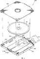
Fig. 3 is the decomposition diagram according to the tray salver of first preferred embodiment of the invention;
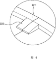
Fig. 4 is the enlarged drawing of accompanying drawing letter A indicating section among Fig. 3;
Fig. 5 shows the planimetric map of the valve open mode of tray salver among Fig. 3;
Fig. 6 is the decomposition diagram according to the tray salver of second preferred embodiment of the invention;
Fig. 7 shows the planimetric map of the valve open mode of tray salver among Fig. 6;
Fig. 8 is the decomposition diagram according to the tray salver of third preferred embodiment of the invention;
Fig. 9 is the enlarged drawing of accompanying drawing letter b indicating section among Fig. 8;
Figure 10 is the enlarged drawing of accompanying drawing letter C indicating section among Fig. 8; With
Figure 11 shows the planimetric map of the valve open mode of tray salver among Fig. 8.
Embodiment
Fig. 3 to Fig. 5 shows the tray salver according to first preferred embodiment of the invention.With reference to figure 3, tray salver 200 comprises: hold the housing 201 of dish D, opening and closing are formed on the housing 201 and the lid 203 (optionally) of the upper surface of the valve 210 of the open pore 202 under dish D and casing 201.
Herein, valve 210 comprises: be installed in the rotatable first and second valve parts 211 and 212 in the housing 201 symmetrically.Like this, as shown in Figure 5, because the first and second valve parts 211 and opened very greatly in 212 minutes, open pore 202 is opened.As shown in Figure 3, when the first and second valve parts 211 and 212 by making the rotation of its direction of closing, open pore 202 is closed.Drawing reference numeral 213 is to connect the first and second valve parts 211 and 212 to make its interactional mate gear part.In view of the above, because 211 rotations of the first valve part, the second valve part 212 is engaged gear parts 213 by opposite direction rotation.
Though do not illustrate among the figure, counterclockwise the torsionspring of the fexible bias pressure first valve part 211 (promptly by the direction of cutting out open pore 202) is installed on the turning axle 210a between the bottom surface of the first valve part 211 and housing 201.Like this, after the power that is applied by opening lever 120 removed, valve 210 returned to initial closed condition.
The support section 220 and 230 that contacts with the external margin of dish D is from the first and second valve parts 211 and 212 projectioies.Promptly coil the clamp area D1 of inner circumferential side that D is included in dish D, the block of information D2 of recorded information and at the marginal portion D3 of the outer circumferential sides of block of information D2.Support section 220 and 230 supports the marginal portion D3 of one of non-block of information to avoid the contact between valve 210 and the block of information D2.As shown in Figure 4, support section 220 upside in the drawings comprises: along the flat 221 of the circumference formation of coiling D with to the centroclinal sloping portion 222 that coils D.Like this, contact with the block of information D2 of dish D though seem sloping portion 222 in Fig. 5, in fact, sloping portion 222 is can not contacting with dish D of inclination.On the contrary, the marginal portion D3 of sloping portion 222 supporting disk D when valve 210 is in open mode.Promptly because the turning axle 210a of valve 210 does not match with the center of coiling D, when valve 210 was opened, flat 221 had departed from the position of the marginal portion D3 of supporting disk D a little.Herein, sloping portion 222 replaces flat 221 bearing edge part D3.
As shown in Figure 5, in the tray salver 200 with said structure is packed disc driving equipment into, the opening lever 120 that is installed in the disc driving equipment presses locking piece 211a that protruding 211c is unclamped from groove 201a, promotes the interference piece 211b first valve part 211 that turns clockwise then.Then, the second valve part 212 is rotated counterclockwise under the effect of mate gear part 213, and the open pore 202 between the first and second valve parts 211 and 212 is opened.But have only the first and second valve parts 211 to contact with dish D with 230 with 212 support section 220, and support section is limited in coiling the marginal portion D3 of D, in the switching manipulation process of valve 210, be difficult to and cause damage to the block of information D2 of recording surface like this.
And, when valve 210 is closed open pore 202, when turning back to state shown in Figure 3 because shutoff operation be support section 220 and 230 and the marginal portion D3 state of contact of dish D under carry out, so the block of information D2 of protective disc D that can safety.
Fig. 6 and Fig. 7 show tray salver according to a second, preferred embodiment of the present invention.Represent to have the similar elements of identical function with drawing reference numeral identical in first preferred embodiment.
In this preferred embodiment, it is characterized in that: the support section 240 of the marginal portion D3 of supporting disk D is formed directly into the basal surface of housing 201, rather than on valve 210.Promptly rely on support section 240 is formed on fixing basal surface rather than on valve of the removable end 210, comes supporting disk D.Can prevent the contact between valve 210 and the dish D at all.Certainly, support section 240 must be formed on not the position of interfering with the rotary area of valve 210.
As shown in Figure 5, in the tray salver 200 with said structure is packed disc driving equipment into, the opening lever 120 that is installed in the disc driving equipment presses locking piece 211a that protruding 211c is unclamped from groove 201a, promotes the interference piece 211b first valve part 211 that turns clockwise then.Then, the second valve part 212 is rotated counterclockwise under the effect of mate gear part 213, and the open pore 202 between the first and second valve parts 211 and 212 is opened.But in the operating process of valve 210, because the supported part 240 of dish D supports and do not contact with valve 210, so eliminated the danger that the block of information D2 of recording surface is damaged.Like this, when the valve 210 in being installed in housing 201 opens or closes, can prevent that the block of information D2 that coils D from sustaining damage.
Fig. 8 is the decomposition diagram according to the tray salver of third preferred embodiment of the invention.Fig. 9 is the enlarged drawing of accompanying drawing letter b indicating section among Fig. 8.Figure 10 is the enlarged drawing of accompanying drawing letter C indicating section among Fig. 8.Figure 11 shows the planimetric map of the valve open mode of tray salver among Fig. 8.
Represent to have the similar elements of identical function with drawing reference numeral identical in the above preferred embodiment.With reference to figure 8, comprise: hold the housing 201 of dish D, open and close and be formed on the housing 201 and the valve 210 of the open pore 202 under dish D according to the tray salver 200 of third preferred embodiment of the invention.
The a plurality of support sections 250 that contact with clamp area D1 (being arranged on the non-block of information of the inner periphery of dish D) are formed on the housing 201 and are protruding from it. Guide channel 215 and 216 is formed on and prevents from the valve 210 to contact with support section 250 when valve 210 opens and closes and interfere.
With reference to figure 9 and 10, support section 250 comprises: extend and projection surpasses the bossing 251 of valve 210 upper surfaces from housing 201, be formed on bossing 251 tops and be used for the contact portion 252 of clamp area D1 of contact disc D.
Have the user to push valve 210 accidentally when operation tray salver 200, valve 210 is touched part 252 and blocks, and can not contact with the block of information D2 of dish D.
At block of information D2 with clamp area D1 recorded information and the dish D that is arranged in the marginarium D3 outside the D2 of block of information, because the supported part 250 of the clamp area D1 of one of non-block of information supports, block of information D2 can avoid contacting with valve 210.And when valve 210 was closed, support section 252 can prevent the contact between block of information D2 and the valve 210.
Though support section 252 is a rectangle in this preferred embodiment, the present invention is not restricted to rectangle with it, and the different shape (as cylinder) with identical function all can use at this.
Operation with tray salver of said structure is described subsequently.
As shown in figure 11, in the disc driving equipment (not shown) of packing into according to the tray salver 200 of this preferred embodiment, the opening lever that is installed in the disc driving equipment presses locking piece 211a that protruding 211c is unclamped from groove 201a.Opening lever 120 promotes the interference piece 211b first valve part 211 that turns clockwise then.Therefore, the second valve part 212 is rotated counterclockwise under the effect of mate gear part 213, and the open pore 202 between the first and second valve parts 211 and 212 is opened.
Herein, because support section 252 only contacts with the clamp area D1 of dish D, so in the process that valve 210 opens and closes, the block of information D2 of recording surface can not be scratched.And, closed open pore 202 when valve 210 and turned back to state shown in Figure 8, because shutoff operation only with under the clamp area D1 state of contact of dish D carries out at support section 252, so the block of information D2 of protective disc D safely.
As mentioned above, tray salver of the present invention has following advantage.
The first, because the support section that is formed on valve or the housing only connects with the non-information area of coiling Touch, then open and close in the operation of open pore at valve, but the information area of safeguard protection dish.
The second, even on the valve that has external force to be applied to close, the supported part of valve is blocked, anti-End further pushing, but the information area of protective disc.
Claims (7)
1. tray salver, comprising: hold the housing of dish, this dish comprises a block of information and a non-block of information; Be installed in the valve that can move under dish in the housing, selectively opened/as to close the open pore that is formed in the housing, tray salver comprises:
Support section from the described non-block of information of the supporting disk of valve projection.
2. tray salver according to claim 1 is characterized in that, non-block of information is the marginal portion that is positioned at dish exterior periphery side.
3. a tray salver comprises: the housing that holds dish; Be installed in the valve that can move under dish in the housing, selectively opened/as to close the open pore that is formed in the housing, tray salver comprises:
Be formed on a plurality of support sections of housing upper support as the inner periphery of the non-block of information of dish; With
Be formed on the guide channel on the valve, described support section is guided in described guide channel, and valve is not interfered with support section when being opened or closed with convenient valve.
4. tray salver according to claim 3 is characterized in that support section comprises: the bossing that stretches out from housing is used for the contact portion that contacts with the inner periphery of dish with being arranged on the bossing top.
5. tray salver according to claim 4 is characterized in that, the length of contact portion one side is provided with greatlyyer than the width of guide channel.
6. tray salver, comprising: hold the housing of dish, this dish comprises a block of information and a non-block of information; Be installed in the valve that can move under dish in the housing, selectively opened/as to close the open pore that is formed in the housing, tray salver comprises:
Be arranged on the support section on the housing, it is not being given prominence to and the described non-block of information of supporting disk from housing with the position of valve interference.
7. tray salver according to claim 6 is characterized in that, non-block of information is the marginal portion that is positioned at the exterior periphery of dish.
Applications Claiming Priority (6)
| Application Number | Priority Date | Filing Date | Title |
|---|---|---|---|
| KR1020010064366A KR100823249B1 (en) | 2001-10-18 | 2001-10-18 | A disk cartridge |
| KR64366/01 | 2001-10-18 | ||
| KR64366/2001 | 2001-10-18 | ||
| KR66020/2001 | 2001-10-25 | ||
| KR1020010066020A KR100823251B1 (en) | 2001-10-25 | 2001-10-25 | A disk cartridge |
| KR66020/01 | 2001-10-25 |
Publications (2)
| Publication Number | Publication Date |
|---|---|
| CN1412768A CN1412768A (en) | 2003-04-23 |
| CN100339904C true CN100339904C (en) | 2007-09-26 |
Family
ID=26639407
Family Applications (1)
| Application Number | Title | Priority Date | Filing Date |
|---|---|---|---|
| CNB021444226A Expired - Fee Related CN100339904C (en) | 2001-10-18 | 2002-09-27 | Disk cassette |
Country Status (6)
| Country | Link |
|---|---|
| US (1) | US7143427B2 (en) |
| EP (1) | EP1304699B1 (en) |
| JP (1) | JP3818950B2 (en) |
| CN (1) | CN100339904C (en) |
| DE (1) | DE60220005T2 (en) |
| TW (1) | TWI241562B (en) |
Families Citing this family (7)
| Publication number | Priority date | Publication date | Assignee | Title |
|---|---|---|---|---|
| HUP0400599A2 (en) | 2001-01-12 | 2004-05-28 | Matsushita Electric Ind Co Ltd | Disc cartridge |
| US6910219B2 (en) | 2001-07-06 | 2005-06-21 | Matsushita Electric Industrial Co., Ltd. | Disc cartridge |
| US7124423B2 (en) * | 2002-02-20 | 2006-10-17 | Samsung Electronics Co., Ltd. | Disk cartridge to protect an information area of a disk from being contaminated |
| EP1629497B1 (en) | 2003-04-09 | 2009-07-01 | Panasonic Corporation | Disc cartridge |
| EP1750265B1 (en) | 2003-06-23 | 2009-07-29 | Sony Corporation | Recording medium cartridge |
| JP2005267826A (en) * | 2004-02-18 | 2005-09-29 | Sony Corp | Recording medium driving device, electronic device equipped with same, and recording medium cartridge |
| RU2430433C2 (en) * | 2006-04-27 | 2011-09-27 | Панасоник Корпорэйшн | Cartridge for disc |
Citations (2)
| Publication number | Priority date | Publication date | Assignee | Title |
|---|---|---|---|---|
| CN1143249A (en) * | 1994-01-28 | 1997-02-19 | 索尼公司 | Cassette disc |
| KR20010082025A (en) * | 2000-02-14 | 2001-08-29 | 이데이 노부유끼 | Disk cartridge |
Family Cites Families (19)
| Publication number | Priority date | Publication date | Assignee | Title |
|---|---|---|---|---|
| JPS60159575A (en) | 1984-01-27 | 1985-08-21 | 三菱電機株式会社 | Refrigerator |
| DE3777368D1 (en) * | 1986-07-04 | 1992-04-16 | Sony Corp | DISK CASSETTE. |
| JPS6355269A (en) | 1986-08-23 | 1988-03-09 | 株式会社長谷工コーポレーション | Temporary constructed holder of reinforcing bar joint |
| EP0358442B1 (en) * | 1988-09-09 | 1995-02-22 | Canon Kabushiki Kaisha | Disk cartridge |
| JPH03134860A (en) | 1989-10-20 | 1991-06-07 | Clarion Co Ltd | Disk loading mechanism |
| US5717684A (en) * | 1990-01-29 | 1998-02-10 | Dai Nippon Insatsu Kabushiki Kaisha | Disk cartridge having chamfered wall portion |
| JP2618790B2 (en) | 1992-07-27 | 1997-06-11 | 大日本スクリーン製造株式会社 | Metal sheet conveyor |
| CN1088893C (en) * | 1994-12-29 | 2002-08-07 | 索尼公司 | Disk cartridge |
| JPH09245452A (en) * | 1996-03-07 | 1997-09-19 | Sony Corp | Disc cartridge |
| JPH09251748A (en) * | 1996-03-13 | 1997-09-22 | Sony Corp | Disk cartridge |
| US5898664A (en) * | 1996-03-19 | 1999-04-27 | Sony Corporation | Position controlling mechanism for a disc cartridge |
| JPH1064224A (en) * | 1996-08-26 | 1998-03-06 | Sony Corp | Removable disk cartridge |
| JP3480220B2 (en) | 1997-02-17 | 2003-12-15 | 三菱化学株式会社 | Disk storage cartridge |
| US5974026A (en) * | 1997-11-14 | 1999-10-26 | Castlewood Systems, Inc. | Anti-rattle mechanism for a removable video disk cartridge |
| JP4103257B2 (en) * | 1998-07-13 | 2008-06-18 | ソニー株式会社 | Disc cartridge |
| JP2001148175A (en) * | 1999-11-24 | 2001-05-29 | Sony Corp | Disk cartridge |
| JP2002056313A (en) | 2000-08-09 | 2002-02-20 | Nec Corp | Electronic data offer system and method |
| HUP0400599A2 (en) * | 2001-01-12 | 2004-05-28 | Matsushita Electric Ind Co Ltd | Disc cartridge |
| KR100788651B1 (en) * | 2002-01-10 | 2007-12-26 | 삼성전자주식회사 | A disk cartridge |
-
2002
- 2002-09-05 TW TW091120251A patent/TWI241562B/en not_active IP Right Cessation
- 2002-09-27 CN CNB021444226A patent/CN100339904C/en not_active Expired - Fee Related
- 2002-10-07 JP JP2002294092A patent/JP3818950B2/en not_active Expired - Fee Related
- 2002-10-11 EP EP02257086A patent/EP1304699B1/en not_active Expired - Fee Related
- 2002-10-11 DE DE60220005T patent/DE60220005T2/en not_active Expired - Lifetime
- 2002-10-18 US US10/273,366 patent/US7143427B2/en not_active Expired - Fee Related
Patent Citations (2)
| Publication number | Priority date | Publication date | Assignee | Title |
|---|---|---|---|---|
| CN1143249A (en) * | 1994-01-28 | 1997-02-19 | 索尼公司 | Cassette disc |
| KR20010082025A (en) * | 2000-02-14 | 2001-08-29 | 이데이 노부유끼 | Disk cartridge |
Also Published As
| Publication number | Publication date |
|---|---|
| US7143427B2 (en) | 2006-11-28 |
| DE60220005T2 (en) | 2008-01-10 |
| EP1304699B1 (en) | 2007-05-09 |
| EP1304699A2 (en) | 2003-04-23 |
| CN1412768A (en) | 2003-04-23 |
| JP3818950B2 (en) | 2006-09-06 |
| JP2003178544A (en) | 2003-06-27 |
| DE60220005D1 (en) | 2007-06-21 |
| US20030128653A1 (en) | 2003-07-10 |
| EP1304699A3 (en) | 2003-08-27 |
| TWI241562B (en) | 2005-10-11 |
Similar Documents
| Publication | Publication Date | Title |
|---|---|---|
| CN100339904C (en) | Disk cassette | |
| EP1474801B1 (en) | Disc cartridge | |
| US20030235144A1 (en) | Disc cartridge and disc drive using the same | |
| CN1136570C (en) | Cartridge for accommodating optical discs of different sizes | |
| CN1282973C (en) | Disk cartridge | |
| US20030179696A1 (en) | Disk cartridge | |
| EP1476868B1 (en) | Disk cartridge | |
| US7103901B2 (en) | Disc cartridge | |
| US20030156533A1 (en) | Disk cartridge and risk player using the same | |
| KR100823249B1 (en) | A disk cartridge | |
| CN1623202A (en) | Disk cartridge | |
| KR20030033856A (en) | A disk cartridge | |
| CN1647199A (en) | Disk cartridge | |
| CN1655267A (en) | Disk drive with disk cartridge | |
| JPH07235160A (en) | Disc container case | |
| JP2004110955A (en) | Optical recording medium drive device | |
| KR20030032547A (en) | Disk cartridge |
Legal Events
| Date | Code | Title | Description |
|---|---|---|---|
| C06 | Publication | ||
| PB01 | Publication | ||
| C10 | Entry into substantive examination | ||
| SE01 | Entry into force of request for substantive examination | ||
| C14 | Grant of patent or utility model | ||
| GR01 | Patent grant | ||
| CF01 | Termination of patent right due to non-payment of annual fee |
Granted publication date: 20070926 Termination date: 20160927 |
|
| CF01 | Termination of patent right due to non-payment of annual fee |