CN100339635C - Connector - Google Patents
Connector Download PDFInfo
- Publication number
- CN100339635C CN100339635C CNB008157626A CN00815762A CN100339635C CN 100339635 C CN100339635 C CN 100339635C CN B008157626 A CNB008157626 A CN B008157626A CN 00815762 A CN00815762 A CN 00815762A CN 100339635 C CN100339635 C CN 100339635C
- Authority
- CN
- China
- Prior art keywords
- valve body
- housing
- pressed
- basic courses
- courses department
- Prior art date
- Legal status (The legal status is an assumption and is not a legal conclusion. Google has not performed a legal analysis and makes no representation as to the accuracy of the status listed.)
- Expired - Fee Related
Links
Images


Classifications
-
- H—ELECTRICITY
- H01—ELECTRIC ELEMENTS
- H01R—ELECTRICALLY-CONDUCTIVE CONNECTIONS; STRUCTURAL ASSOCIATIONS OF A PLURALITY OF MUTUALLY-INSULATED ELECTRICAL CONNECTING ELEMENTS; COUPLING DEVICES; CURRENT COLLECTORS
- H01R13/00—Details of coupling devices of the kinds covered by groups H01R12/70 or H01R24/00 - H01R33/00
- H01R13/46—Bases; Cases
- H01R13/52—Dustproof, splashproof, drip-proof, waterproof, or flameproof cases
-
- A—HUMAN NECESSITIES
- A61—MEDICAL OR VETERINARY SCIENCE; HYGIENE
- A61M—DEVICES FOR INTRODUCING MEDIA INTO, OR ONTO, THE BODY; DEVICES FOR TRANSDUCING BODY MEDIA OR FOR TAKING MEDIA FROM THE BODY; DEVICES FOR PRODUCING OR ENDING SLEEP OR STUPOR
- A61M39/00—Tubes, tube connectors, tube couplings, valves, access sites or the like, specially adapted for medical use
- A61M39/22—Valves or arrangement of valves
- A61M39/26—Valves closing automatically on disconnecting the line and opening on reconnection thereof
-
- A—HUMAN NECESSITIES
- A61—MEDICAL OR VETERINARY SCIENCE; HYGIENE
- A61M—DEVICES FOR INTRODUCING MEDIA INTO, OR ONTO, THE BODY; DEVICES FOR TRANSDUCING BODY MEDIA OR FOR TAKING MEDIA FROM THE BODY; DEVICES FOR PRODUCING OR ENDING SLEEP OR STUPOR
- A61M39/00—Tubes, tube connectors, tube couplings, valves, access sites or the like, specially adapted for medical use
- A61M39/02—Access sites
- A61M39/04—Access sites having pierceable self-sealing members
- A61M39/045—Access sites having pierceable self-sealing members pre-slit to be pierced by blunt instrument
-
- F—MECHANICAL ENGINEERING; LIGHTING; HEATING; WEAPONS; BLASTING
- F16—ENGINEERING ELEMENTS AND UNITS; GENERAL MEASURES FOR PRODUCING AND MAINTAINING EFFECTIVE FUNCTIONING OF MACHINES OR INSTALLATIONS; THERMAL INSULATION IN GENERAL
- F16L—PIPES; JOINTS OR FITTINGS FOR PIPES; SUPPORTS FOR PIPES, CABLES OR PROTECTIVE TUBING; MEANS FOR THERMAL INSULATION IN GENERAL
- F16L29/00—Joints with fluid cut-off means
- F16L29/005—Joints with fluid cut-off means joints with cut-off devices which can be perforated
-
- F—MECHANICAL ENGINEERING; LIGHTING; HEATING; WEAPONS; BLASTING
- F16—ENGINEERING ELEMENTS AND UNITS; GENERAL MEASURES FOR PRODUCING AND MAINTAINING EFFECTIVE FUNCTIONING OF MACHINES OR INSTALLATIONS; THERMAL INSULATION IN GENERAL
- F16L—PIPES; JOINTS OR FITTINGS FOR PIPES; SUPPORTS FOR PIPES, CABLES OR PROTECTIVE TUBING; MEANS FOR THERMAL INSULATION IN GENERAL
- F16L29/00—Joints with fluid cut-off means
- F16L29/02—Joints with fluid cut-off means with a cut-off device in one of the two pipe ends, the cut-off device being automatically opened when the coupling is applied
-
- F—MECHANICAL ENGINEERING; LIGHTING; HEATING; WEAPONS; BLASTING
- F16—ENGINEERING ELEMENTS AND UNITS; GENERAL MEASURES FOR PRODUCING AND MAINTAINING EFFECTIVE FUNCTIONING OF MACHINES OR INSTALLATIONS; THERMAL INSULATION IN GENERAL
- F16L—PIPES; JOINTS OR FITTINGS FOR PIPES; SUPPORTS FOR PIPES, CABLES OR PROTECTIVE TUBING; MEANS FOR THERMAL INSULATION IN GENERAL
- F16L37/00—Couplings of the quick-acting type
- F16L37/28—Couplings of the quick-acting type with fluid cut-off means
- F16L37/38—Couplings of the quick-acting type with fluid cut-off means with fluid cut-off means in only one of the two pipe-end fittings
-
- A—HUMAN NECESSITIES
- A61—MEDICAL OR VETERINARY SCIENCE; HYGIENE
- A61M—DEVICES FOR INTRODUCING MEDIA INTO, OR ONTO, THE BODY; DEVICES FOR TRANSDUCING BODY MEDIA OR FOR TAKING MEDIA FROM THE BODY; DEVICES FOR PRODUCING OR ENDING SLEEP OR STUPOR
- A61M39/00—Tubes, tube connectors, tube couplings, valves, access sites or the like, specially adapted for medical use
- A61M39/22—Valves or arrangement of valves
- A61M39/26—Valves closing automatically on disconnecting the line and opening on reconnection thereof
- A61M2039/261—Valves closing automatically on disconnecting the line and opening on reconnection thereof where the fluid space within the valve is increasing upon disconnection
Abstract
A connector (1) used for various medical instruments, infusion containers, and infusion devices to connect a tube (4). The connector (1) includes a cylindrical valve (3) made of elastic material with a closable slit (33) so that a tube (4) can be connected without passing through the valve (3).
Description
Technical field
The present invention relates to a kind of connector, specifically relate to for example employed in various medical apparatuss or infusion vessel, feed flow apparatus etc., in order to connect the connector of body.
Background technique
The present invention relates to a kind of for example employed in various medical apparatuss or infusion vessel, feed flow apparatus etc., connector (adapter) in order to connect body.
In the past, this connector is to be made of housing that forms stream and valve body, this valve body is made up of elastic material, and be installed in the body connection mouth place in this housing, switching mechanism by valve body, when valve body openings, body definitely is connected with the stream of connector, the fluid (liquid etc.) that flows in the body is delivered in the connector.
In these connectors,,, and wish to have the connector of what is called " needleless " type that can open and close repeatedly because worry is not sharp-pointed pin owing to the blood infection that contingent causes so wish valve body openings especially for the connector of medical treatment.
The 1st example of this style connector, for example specially open flat 8-243092 communique, special table flat 8-500983 number, special table flat 10-512946 number and specially open that flat 10-118178 communique etc. announced, mechanism has slit etc., when disconnected inaccessible valve body by connecting intubate, outer Rule bodys such as (Ruhr) valve body openings, body is connected with the stream of connector.
As the 2nd example, for example open that flat 9-108361 communique announced the spy, connector is to be made of valve body and housing, and valve body is that the piston head of the elliptical shape of opening (submarine mine type hole) constitutes by for example having, and housing has the connection mouth littler than this piston crown diameter, when disconnected, the head of elliptical shape is pressed into than in the little housing of piston diameter and inaccessible hole, in addition, when body connects, at the body front-end face, piston retreats into large diameter housing parts, head returns to original elliptical shape like this, and open in submarine mine shape hole, opens stream therefrom.And, other example as the needle-free connector that does not connect the valve body type, having of motion: structure with driving means such as outside threads, and this outside thread has the conical surface for compression valve, come compression valve and make its distortion by outside thread with conical surface, open valve slit (special table flat 7-502420 number) therefrom, the connector of Gong Buing also has in addition: or have the valve of forming by the slanted bar and the lid of snake abdomen shape, and has a driving means for open and close valve (in step up part), the flange of valve gap of being pushed by driving means and the slanted bar part that links to each other therewith comes the artificial opening portion of blocking valve holding member, make the stream sealing like this, in addition, use the injector compression cover from the outside, when artificial opening portion was opened, the otch (guiding groove) and the shunt opening portion that are located at the path direction of slanted bar part formed stream (special table flat 7-502421 number).
But, above-mentioned pass through to connect body and the connector of the 1st example of valve body openings, exist the excessive problem of valve body openings diameter.And the existing problem of connector that is pre-formed open pore is: when body when connector takes out, have liquid to flow backwards and the situation of leaking from the terminal side of connector.
And, the front end of body connected valve body and entering structure in the connector, the problem of existence is: the bacterium attached to the body front end can enter in the stream of connector, has the danger of polluting.
In addition, because the connector of the 2nd example is the structure that body does not connect valve body, thus there is not the similar problem of the 1st routine connector, but the problem that has sealing and connect certainty.Specifically, because the structure of the connector of the 2nd example is a cardinal extremity face of the front-end face of body being pushed down valve body, the close property of its liquid mainly depends on the surface of contact of the cardinal extremity face of the front-end face of body and valve body and presses, so, under the big situation of the interior pressure of connector, there is the danger of leak of liquid.And, if need not king-sizedly defeat when tight, have the danger of throwing off that is connected of body and valve body owing to both cooperate degree.
Summary of the invention
Therefore, the purpose of this invention is to provide that a kind of part count is few, simple structure and wieldy connector, when being connected with body, stream in the connector can be not contaminated, body can be connected with the close property of high liquid (sealing) definitely with connector, and can prevent when body connects and the leak of liquid after body is taken out from connector.
Can reach such purpose by following embodiment.
(1) a kind of connector, it has housing and valve body, this housing has the connection mouth of connection body and is formed with fluid passage in inside, this valve body is arranged in the aforementioned housing and by elastic material and constitutes, it is characterized in that, this valve body has tubular basic courses department, portion and slit are pressed, this tubular basic courses department has the conical surface that wall thickness forward end side direction increases progressively, the aforementioned portion of being pressed is arranged on and contacts on the axial end of aforementioned basic courses department and with light-emitting diode body and be subjected to pressing force, and aforementioned slit is formed in the aforementioned portion that is pressed and opens because of being subjected to pressing force; Be fixed by housing near the opening portion of described valve body, when not connecting body or when body connects disconnection, return to the valve body of this slit obturation, seal the inner chamber of described basic courses department and the path in the inaccessible housing by the described portion of being pressed; When this is pressed portion when bearing the pressure opening, the block channels of described basic courses department is communicated with path in the housing; Be pressed portion and when being connected on this connection mouth of this housing of this that push aforementioned valve body in light-emitting diode body, this valve body resiliently deformable and this slit open, simultaneously, because this wall thickness increases progressively towards forward end, so this forward end of bending strength ratio of terminal side little also produces more large deformation, thereby closely touch mutually with the front-end face of this body and the outer circumferential face of this front end.
(2) as (1) described connector in, in the described portion and when being connected on this connection mouth of this housing of being pressed that light-emitting diode body is pushed this valve body, aforementioned valve body resiliently deformable and this slit open, simultaneously, described basic courses department's inflection with conical surface that wall thickness forward end side direction increases progressively, this portion of being pressed enters in this basic courses department, and the inner peripheral surface that is formed by the folded part of this basic courses department closely touches mutually with the front end outer circumferential face of this body.
(3) a kind of connector, it has housing and valve body, this housing has the connection mouth of connection body and is formed with fluid passage in inside, this valve body is arranged in this housing and by elastic material and constitutes, it is characterized in that, this valve body has tubular basic courses department, portion and slit are pressed, aforementioned tubular basic courses department has the conical surface that wall thickness increases progressively towards the forward end direction, the aforementioned portion of being pressed is arranged on and contacts on the axial end of aforementioned basic courses department and with light-emitting diode body and be subjected to pressing force, and this slit is formed in this portion that is pressed and opens because of being subjected to pressing force; Be fixed by housing near the opening portion of this valve body, when not connecting body or when body connects disconnection, return to the valve body of this slit obturation, seal the inner chamber of described basic courses department and the path in the inaccessible housing by the described portion of being pressed; When this is pressed portion when bearing the pressure opening, the block channels of described basic courses department is communicated with path in the housing; Be pressed portion and when being connected on this connection mouth of this housing of this that push this valve body at this body, this valve body resiliently deformable and aforementioned slit open, simultaneously, increase progressively because this wall thickness is distolateral forward, so the bending strength ratio forward end of terminal side little also produces more large deformation, this terminal side closely touches mutually with this body, and this tight contact segment is absorbed in the inside of aforementioned basic courses department.
(4) a kind of connector, it has housing and valve body, aforementioned housing has the connection mouth of connection body and is formed with fluid passage in inside, this valve body is arranged in the aforementioned housing and by elastic material and constitutes, it is characterized in that, this valve body has tubular basic courses department, portion and slit are pressed, this tubular basic courses department has the conical surface that wall thickness forward end side direction increases progressively, this portion of being pressed is arranged on and contacts on the axial end of this basic courses department and with this body and be subjected to pressing force, and this slit is formed in this portion that is pressed and opens because of being subjected to pressing force; Be fixed by housing near the opening portion of this valve body, when not connecting body or when body connects disconnection, return to the valve body of this slit obturation, seal the inner chamber of described basic courses department and the path in the inaccessible housing by the described portion of being pressed; The gap that allows this basic courses department's hole enlargement is arranged between described basic courses department and described housing, and when this is pressed portion when bearing the pressure opening, the interior path of the block channels of hole enlargement of described basic courses department and described basic courses department and housing is communicated with; Be pressed portion and when being connected on this connection mouth of this housing of this that push this valve body at this body, this valve body resiliently deformable and this slit open, simultaneously, the hole enlargement of aforementioned basic courses department, because this wall thickness increases progressively towards forward end, so the bending strength ratio forward end of terminal side is little and produce more large deformation thus.
(5) a kind of connector, it has housing and valve body, this housing has the connection mouth of connection body and is formed with fluid passage in inside, this valve body is arranged in this housing and by elastic material and constitutes, it is characterized in that, this valve body has tubular basic courses department, portion is pressed, slit and fixing part, aforementioned tubular basic courses department has the conical surface that wall thickness forward end side direction increases progressively, this portion of being pressed is arranged on and contacts on the axial end of this basic courses department and with this body and be subjected to pressing force, this slit is formed in the aforementioned portion that is pressed and opens because of being subjected to pressing force, and this fixing part is arranged on the axial the other end of this basic courses department and also this valve body is fixed on this housing; In this housing, be formed with the space of avoiding of the fixing part side that can insert this basic courses department; In the housing of this cardinal extremity lateral side, form the valve body supporting portion, the flange that on the front edge of valve body base end part, is formed with expanded outer diameter and forms, valve body by liquid-tight be fixed on the housing, when not being connected on the body or when body connects disconnection, return to the valve body of slit obturation, seal the inner chamber of described basic courses department and the path in the inaccessible housing by the described portion of being pressed; The gap that allows this basic courses department's hole enlargement is arranged between described basic courses department and described housing, and when this is pressed portion when bearing the pressure opening, the interior path of the block channels of hole enlargement of described basic courses department and described basic courses department and housing is communicated with; Be pressed portion and when being connected on this connection mouth of this housing of this that push this valve body at this body, this valve body resiliently deformable and this slit open, simultaneously, because this wall thickness increases progressively towards forward end, so, the bending strength ratio forward end of terminal side is little and produce more large deformation thus, and near the front end of described basic courses department part and this flange enters aforementioned avoiding in the space.
(6) as (5) described connector in, when this that push this valve body when this body was pressed portion, this basic courses department was compressed and hole enlargement vertically.
(7) as the described connector in one of (1)-(6) in, received connection on this connection mouth when being disengaged at this body, this valve body can return to original form.
(8) in as one of (1)-(6) described connector, this slit forms with such size,, even if when this slit opens maximum, does not also allow the external diameter greater than this body that is.
(9) as (8) described connector in, the central part of the aforementioned portion that is pressed has heavy section, forms aforementioned slit on this heavy section.
(10) in one of (1)-(6) described connector: at least a portion of this basic courses department is such taper, and promptly external diameter or internal diameter increase progressively to the terminal side direction from this portion that is pressed.
(11) in as one of (1)-(6) described connector, this portion that is pressed has protuberance and/or recess in a side of this body front-end face of contact.
(12) as (11) described connector in, this portion that is pressed has the 1st protuberance in the side of front-end face of this body of contact.
(13) as (12) described connector in, the 1st protuberance roughly becomes dome shape.
(14) in as one of (1) or (4)-(6) described connector, this portion that is pressed has outstanding protuberance in a side of the front-end face that does not contact this body.
(15) as (14) described connector in, this protuberance forms the part of sphere.
In connector of the present invention, can form the space in the inboard of aforementioned housing, and be provided with flange at the outer circumferential face of aforementioned valve body, the said flange of aforementioned valve body is cooperated with the aforementioned interspace of aforementioned housing.In addition, aforementioned housing can be made of two parts, and the gap part that forms between these two parts inserts said flange, and the aforementioned relatively housing of aforementioned valve body is fixed.
Description of drawings
Fig. 1 is the sectional arrangement drawing of a form of implementation of the connector that the present invention relates to of expression.
Fig. 2 is that connector shown in Figure 1 is from the planimetric map shown in the terminal side.
The connector of Fig. 3 presentation graphs 1 and body are the sectional arrangement drawings of the state of front-end face position when determining of expression body.
Fig. 4 represents connector and the body suitable with Fig. 1, is the sectional arrangement drawing of the state of front-end face when roughly consistent with the housing cardinal extremity face of connector of expression body.
Fig. 5 represents connector and the body suitable with Fig. 1, is the sectional arrangement drawing that the front end of expression body inserts the state in the housing connection mouth of connector.
Fig. 6 represents connector and the body suitable with Fig. 1, is the sectional arrangement drawing of expression body state that the connection of connector is finished (front end of body enters the state in the middle footpath space portion of connector shell).
Fig. 7 represents the sectional arrangement drawing of other form example of connector of the present invention, and this form example is to be formed with the gap that allows the hole enlargement valve body in housing.
Fig. 8 is the sectional arrangement drawing of other form example of expression connector of the present invention.
Fig. 9 is that the connector of other form example of the present invention is from the planimetric map shown in the terminal side.
Figure 10 is the sectional arrangement drawing that comprises body along the X-X line of connector among Fig. 9.
Figure 11 is the sectional arrangement drawing that comprises body along the XI-XI line of connector among Figure 10.
Figure 12 is illustrated in the form example of Figure 11, the sectional arrangement drawing of the state when connector is determined the front-end face position of body.
Figure 13 is illustrated in the form example of Figure 11, the sectional arrangement drawing of the state in the connection mouth of the front end of body insertion cylindrical shell.
Figure 14 is illustrated in the form example of Figure 11, the sectional arrangement drawing of body and the state of finishing being connected of connector (front end of body enters the state in the middle footpath portion of cylindrical shell).
Figure 15 is illustrated in the form example of Figure 11 the sectional arrangement drawing of other shape of valve body supporting portion.
Figure 16 is the planimetric map of other form example of expression valve body.
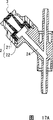
Figure 17 is the sectional arrangement drawing of expression Y-shaped housing connector form example.
Figure 18 is the sectional arrangement drawing of expression T font housing connector form example.
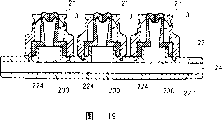
Figure 19 is the sectional arrangement drawing of a plurality of connector form examples arranged side by side of expression.
Embodiment
Below, specify form of implementation of the present invention with reference to accompanying drawing.In addition, in the following description, in each sectional arrangement drawing (for example: Fig. 1, Fig. 3~Fig. 6 and other suitable therewith figure) of connector, figure upside (body connection side) is called " cardinal extremity ", downside is called " front end ".
Fig. 1 is an embodiment of the connector that the present invention relates to, is the sectional arrangement drawing of expression with the part of I type connector that connects between the body and the body that is connected therewith, and Fig. 2 is that connector among Fig. 1 is from the planimetric map shown in the terminal side.
Among Fig. 1 and Fig. 2, connector 1 is the parts that connect body 4, has housing 2 and valve body 3.
In form shown in Figure 1, cylindrical shell 21 is a same outer diameter as from its cardinal extremity 216 sides to front end 217 sides, footpath space portion 212 and the lid assembly department 213 bigger in inside has than this 212 diameter, and middle footpath space portion 212 is the basic courses departments 34 in order to put into valve body 3.The connection mouth 211 that body is arranged at the cardinal extremity 216 of cylindrical shell 21 in addition.The diameter of footpath space portion 212 is little in these connection mouth 211 ratios, and the cardinal extremity part of valve body 3 can seamlessly be inserted.And, when in middle footpath space portion 212, putting into valve body 3, in middle footpath space portion 212, promptly formed the gap 214 that allows basic courses department's 34 hole enlargements between housing and the basic courses department 34.
The external diameter that the cardinal extremity sidepiece 221 of lid 22 has makes in its assembly department that can be installed in cylindrical shell 21 213.Tube end 225 in cardinal extremity sidepiece 221 sides forms valve body supporting portion 226.The cylindrical shell 21 that is formed by assembly department 213 and cardinal extremity sidepiece 221 is connected with lid 22, as long as can connect definitely, its method does not have special qualification, but for example can list: cooperate (specifically be to use the cooperation of riveted joint or screw togather), use binder bonding etc., and when cylindrical shell 21 and lid all be when being made of resin, also can use fusions such as hot melt is separated, ultrasound fusion.
For for example with have flexible body (not shown) and be connected, the front end sidepiece 222 of lid 22 also can be to have the external diameter littler than cardinal extremity sidepiece 221.And the external diameter of front end sidepiece 222 also can be identical, also can be to embed body easily and for Rule taper of the close property of liquid connection.This body (not shown) can list pipe of transfusion device for example etc.
In the front end sidepiece 222 and cardinal extremity sidepiece 221 of lid 22, form space 223,224 respectively, this space 223 and 224 forms the stream 24 that covers in 22.
When cylindrical shell 21 links with lid 22, because the space between the tube end 225 of the internal end surface 215 of cylindrical shell 21 and lid 22, at the full week formation groove 23 in interior week of housing 2.
The constituent material of above-mentioned housing 2, can list for example polyethylene, polypropylene, the ethylene-propylene copolymer zoarium, the polyolefin of ethene-vinyl acetate copolymer (EVA) etc., PVC, polyvinylidene chloride, polystyrene, polyamide, polyimide, polyamide-imide, polycarbonate, poly-(4-methylpentene-1), ionomer, the oleic series resin, polymerthyl acrylate, acrylonitrile-butadiene-styrene terpolymer (ABS resin), acrylonitritrile-styrene resin (AS resin), butadiene-styrene copolymer, polyethylene terephthalate (PET), polybutylene terephthalate (PBT), the polyester of polychlorostyrene terphenyl (PCT) etc., polyethers, polyether-ketone (PEK), polyether-ether-ketone (PEEK), polyimide, polyoxymethylene (POM), the polyphenyl epoxy, the modified polyphenyl epoxy, polysulfonates, polyether sulfone, polyphenylene sulfide, polyarylate, aromatic system polyester (liquid-crystalline polymer), teflon, polyvinylidene fluoride, other fluorine-type resin etc., or comprise these central mixtures more than a kind, various resin materials such as polyblend.And, can also enumerate multiple glass material, stupalith, metallic material as constituent material, also can be composite material with above-mentioned resin material.
The valve body 3 that connector of the present invention comprised is to be made of the basic courses department 34 and the portion 30 that is pressed, and basic courses department 34 is roughly tubular basically, and the portion 30 that is pressed is located at the axial terminal side of this basic courses department 34, and has the slit 33 that can open and close mouth.This valve body 3 when disconnected () when slit 33 is inaccessible, cover inner chamber and stream 24 in the inaccessible housing 2 by the portion of being pressed 30, when being connected, owing to pushing of the front-end face 41 of body 4 with body 4, slit 33 openings, the stream 24 in the stream 43 of valve body 3 and the housing 2 is communicated with.When this opening, the front end of body 4 is not connected slit 33 (portion 30 is pressed) by because the part of the valve body 3 of pushing of body 4 and resiliently deformable (folded deformation) supports.Therefore, even do not use sharp-pointed pin, valve body 3 also can opening, and when breaking away from being connected of body 4, restores again to the valve body of slit 33 obturations.
Below be described in detail this special valve body 3 that can switching mechanism.
Among the present invention, the basic courses department 34 of valve body 3 has the conical surface that its wall thickness forward end side direction increases gradually.The conical surface can be arranged on the inner chamber side or the outer circumferential side of basic courses department 34, also can be arranged on both sides in addition, and, also can be arranged on the whole peripheral surface of basic courses department 34 or be arranged on the part side face.
In form example shown in Figure 1, be that the periphery in basic courses department 34 is provided with this conical surface.The internal diameter of valve body 3 is roughly basic identical from terminal side to forward end, and roughly the same with the diameter (internal diameter of cardinal extremity sidepiece 221) in the lid space 224 of housing 2, and the periphery of valve body 3 forms the conical surface that increases gradually from cardinal extremity face 31 side direction front end boss 35 side directions.Like this, the wall thickness of basic courses department 34 is that the forward end side direction increases gradually.Owing to make such shape, the terminal side of basic courses department 34 is littler than forward end flexural strength, as described later, is pushed by body 4 and when being pressed in the portion of being pressed 30, can be easily and the definite folded part that (repeatability well) forms.
And, the external diameter of the cardinal extremity of basic courses department 34 part and the bore of the connection mouth 211 of cylindrical shell 21 about equally, the cardinal extremity of basic courses department 34 partly can seamlessly insert in the connection mouth 211 of cylindrical shell 21.
The portion that is pressed 30 of valve body 3 is the parts that are subjected to pressing force from the front-end face 41 of body 4, among the present invention, be pressed portion 30 forms the wall thickness of the core of slits 33 than peripheral part, like this, slit 33 easy openings in making in the footpath space portion 212, and make basic courses department's 34 easy bendings, and can be inaccessible definitely slit 33 in the connection mouth 211.Center wall thickness for the feasible portion 30 that is pressed can form projection at least one side of cardinal extremity face 31 sides that contact with the front-end face 41 of body 4 or its inner face 32 sides, and its shape without limits.Cardinal extremity face 31 sides of portion 30 of being pressed can have protuberance or recess, but preferably are to have the protuberance more outstanding laterally than the cardinal extremity 216 of housing 2 on the part of cardinal extremity face 31 at least.
In form example shown in Figure 1, has the 1st protuberance at the cardinal extremity face 31 of the portion of being pressed 30.The 1st protuberance of this cardinal extremity face 31 is more outstanding laterally than the cardinal extremity 216 of housing 2, forms to be roughly dome-shaped (coniform, cap shape, plate-like).Inner face 32 sides in the portion of being pressed 30 have basic courses department 34 that is positioned at valve body 3 and the 2nd protuberance of giving prominence to the 1st protuberance opposite direction of cardinal extremity face 31.The 2nd protuberance forms spherical calotte.
Central part (heavy section) in such portion that is pressed 30 forms the slit 33 that connects the portion 30 that is pressed.Slit 33 is in the raw when (state of no external force effect), since the elasticity of the portion 30 that is pressed and obturation, maintenance liquid close (airtight) state.
Among the present invention, the size of set slit 33 is: even be pressed and slit 33 during to maximum open in the portion of being pressed 30, slit 33 can opening yet to bigger than the external diameter of body 4, can not allow the perforation of body 4.
In illustrated form of implementation, the slit 33 of formation is the joint-cutting (slit) of in-line shape of incision, makes be interconnected between the top of the 2nd protuberance of the 1st protuberance of cardinal extremity face 31 and inner face 32 sides (referring to Fig. 2).
When this slit 33 is in no load condition (state of no external force effect), by inaccessible, keep the close state of liquid (airtight conditions) owing to the elasticity of the portion 30 that is pressed.In the present invention, owing to be to form slit at the thick wall part of the portion of being pressed 30, so, when removing, can access the occlusive (sealing) of excellence with being connected of body 4.
In addition, the shape of slit 33 is unqualified to be illustrated joint-cutting direction, and its shape also unqualified be the in-line shape.
Be fixed in the valve body 3 of housing like this, because its cardinal extremity face 31 is more outstanding than the cardinal extremity 216 of housing 2, so it is desirable to be easy to sterilization.
Secondly, with reference to the bindiny mechanism of figure explanation connector 1 of the present invention with body 4.
Fig. 3 to Fig. 6 is the sectional arrangement drawing suitable with Fig. 1, is the actuating mechanism figure of the state of expression when in order to illustrate in order body 4 being connected connector 1.In Fig. 3~6, the symbolic representation same parts identical with Fig. 1~2.
These body 4 inside have stream, and outer circumferential face preferably forms the Luer taper shape.That is, its shape is: the external diameter of body 4 front ends is smaller a little than the opening diameter (connection bore) of the connection mouth 211 of cylindrical shell 21, and the cone shape that increases gradually towards its external diameter of proximal direction, the external diameter of body 4 cardinal extremities is bigger than the opening diameter of connection mouth 211.Like this, the front end of body 4 can insert in the housing 2 by valve body 3 from connection mouth 211, and can embed connection mouth 211 with the desirable degree of depth.
Fig. 3 is the sectional arrangement drawing of expression with the state of front-end face 41 when connector 1 is determined the position of body.As mentioned above, the slit 33 of valve body 3 is a blocked state when no load condition (state of no external force effect), keeps the close property of liquid.
And, as shown in Figure 3, make that the central shaft of body 4 is consistent with the central shaft of housing 2 to be determined by this state body 4 forward end directions (direction shown in the arrow among the figure) to be moved the position, insert in the connector 1.
Fig. 4 is the state of front-end face 41 when roughly consistent with the cardinal extremity 216 of housing 2 (cylindrical shell 21) of expression body 4.In this position, because pushing of body 4 mainly is the portion's of being pressed 30 change in shape.
Among Fig. 4, when the 1st protuberance of the portion that is pressed 30 (cardinal extremity face 31) of pushing valve body 3 by the front-end face 41 of body 4, because the cardinal extremity face 31 of valve body 3 is subjected to the restriction of the connection mouth 211 of cylindrical shell 21 to expansion radially, so, mainly be that cardinal extremity face 31 produces resiliently deformables.The 1st protuberance of cardinal extremity face 31 is from the dome-shaped plane shape that gradually becomes, and then bending, becomes concavity.
And along with the change in shape of cardinal extremity face 31, so far inaccessible always slit 33 is from the 2nd projection of inner face 32 opening gradually.Here, as long as body 4 is pressed in cardinal extremity face 31 with less power, just can be so that become plane shape also and then become the concavity of bending from dome-type the 1st protuberance.
The state that Fig. 5 represents is: body 4 further forward end directions are moved insert in the connector 1 and the front-end face 41 of body 4 inserts state in the connection mouth 211 of cylindrical shells 21.In this position, owing to pushing of body 4, the shape of basic courses department 34 also changes.As shown in Figure 5, when further pushing the portion 30 that is pressed of valve body 3 by the front-end face 41 of body 4, the portion 30 that is pressed moves to middle footpath space portion 212, and the basic courses department of valve body 3 34 axially is compressed at it.
At this moment, when make the wall thickness (being flexural rigidity) of basic courses department 34 be from the forward end of basic courses department 34 when terminal side reduces gradually, distortion mainly is that the terminal side of basic courses department 34 is radially expanded to foreign side.
In form example shown in Figure 5, owing to making basic courses department's 34 its expansions, the inner peripheral surface of the middle footpath space portion 212 of cylindrical shell 21 is subjected to a certain degree restriction, when the base end part of basic courses department 34 extends to after gap 214 with the inner peripheral surface of middle footpath space portion 212 do not have substantially, just can not continue expansion.
Like this, basic courses department 34 axially is being compressed, and is limit and enlarged and resiliently deformable with the internal diameter of middle footpath space portion 212, and the cardinal extremity face 31 of valve body 3 is pressed down to the cardinal extremity of the middle footpath space portion 212 of cylindrical shell 21.Thus, slit 33 further openings, the stream 43 of body 4 is communicated with stream 24 between the connector 1.
When moving, deeply inserting in the connector 1, become state shown in Figure 6 to body 4 further forward end directions.
The state that Fig. 6 represents is: the front-end face 41 of body 4 enters in the middle footpath space portion 212 of cylindrical shell 21, the state that last body 4 is connected with connector 1.
In this position, when the cardinal extremity face 31 of valve body 3 from Fig. 5 state the cardinal extremity that is positioned at intermediate space portion 212 and when body 4 further forward end directions are pushed, the basic courses department 34 of valve body 3 further axially is being compressed, its voltage endurance capability of terminal side part (parts of portion's 30 sides that are pressed) that flexural rigidity in the basic courses department 34 is little disappears, and bending (folding) to the inside, the terminal side formation folded part 36 in basic courses department 34.
And, in this position, because because the hole enlargement of basic courses department 34, and make that the inner chamber internal diameter of valve body 3 is bigger than the external diameter of body 4, so, between the basic courses department 34 of body 4 and valve body 3, can form space (allowing the hole enlargement space), aforementioned folded part 36 utilizes this space and inserts, and the part of closely touching mutually with body 4 in the base end part of valve body 3 (field) is further pressed down and is enlarged.
As a result, valve body 3 be absorbed in basic courses department 34 inside of valve body 3, and the front end of body 4 becomes the state that encases folded part 36 with the part (field) of closely touching the mutually portion of being pressed 30 and body 4.Like this, the front end outer circumferential face 42 of body 4 closely touches mutually with folded part 36, the result, and body 4 its front-end faces 41 and front end outer circumferential face 42 all closely touch mutually with valve body 3.
Like this, because not only the front-end face 41 of body 4 but also front end outer circumferential face 42 also encase the cardinal extremity face 31 of valve body 3 and folded part 36 and closely touch mutually, so, body 4 increases with the area that closely touches mutually of valve body 3, significantly improve sealing each other (the close property of liquid, tightness), can prevent liquid leakage etc. definitely.
And, as shown in Figure 6, body 4 its external diameters are in position identical with the internal diameter (opening diameter) of connection mouth 211 and connection mouth 211 taper fit, and, because the folded part 36 of the valve body 3 that the front end of body 4 is deformed encases and can be held definitely, so, can prevent to be easy to body 4 is extracted from connector 1.
In the present invention, as shown in Figure 6, when body 4 is connected with connector 1, because the front-end face 41 of body 4 and front end outer circumferential face 42 are not jumped over valve body 3 and are entered in the stream of housing 2, so, can not take place slit 33 excessively to be pushed expansion and cause the rough sledding of the close property of liquid reduction, even and in the occasion that the front-end face 41 and the front end outer circumferential face 42 of body 4 is attached with foreign matter (dust, dust etc.), can prevent that also it from entering in the housing 2 and pollute in the housing 2.
From state shown in Figure 6, when body 4 is moved and when connector 1 is extracted to proximal direction, removed the pressing force that is acted on valve body 3 by body 4, valve body 3 is owing to its flexible self-recovery power, and basic courses department 34 is stretched to the original length, and, in its process, the base end part of valve body 3 enters in the connection mouth 211 of cylindrical shell 21, and the portion that is pressed 30 of valve body 3 returns to original shape, its the 1st protuberance 31 is outstanding from connection mouth 211, becomes state shown in Figure 1.
And, if valve body 3 turns back to original shape, then recovered the close property of liquid because slit 33 quilts are inaccessible once more, so, after body 4 is extracted from connector 1,, can prevent that also this fluid from flowing out from the terminal side of connector 1 even for example fluid flows backwards to proximal direction.
Shown in above-mentioned form of implementation, if have the heavy wall place formation slit 33 of the portion that is pressed 30 of protuberance in cardinal extremity face 31 and inboard 32 both sides, then compare with the situation that on the flat board of same thickness, forms slit, because can improve the sealing of slit 33 when obturation, so, during for the situations such as rising of the interior pressure of housing 2, can more properly prevent leak of liquid.
And, as mentioned above, do not connect the slit of valve bodies 3 and connect because connector 1 is a body 4, so slit 33 can hyper expanded, the result, even carry out repeatedly under the situation of repeatedly clutch at connector 1 and body 4, also can not reduce the sealing at slit 33 places of valve body 3.
More than be connector of the present invention to be illustrated according to an illustrated form of implementation, but the present invention is not limited thereto, the structure of each several part, the particularly shape of the shape of valve body, structure, housing, structure etc., if in the scope that can reach said function, can be parts arbitrarily, all distortion can be arranged.For example, also can enumerate following several variation at above-mentioned form of implementation.
1. in aforementioned form of implementation, be cylindrical shell 21 with housing for example as shape, the structure that can be connected with body 4, but also can be shape, the structure that can connect such as Rule taper or location, Rule for example.
And though be that the form that connects situation between the single body is illustrated for example, its shape of housing of the body connection part of connector, branch way etc. are arbitrarily.For example can enumerate different shapes such as branch's (Y-shaped) connector, T font connector, J shape annular, PRN connector.
2. in aforementioned form of implementation, valve body 3 is different parts with housing 2, but also can be to utilize 2 look moulding or insertion moulding etc. that valve body 3 is formed as one with cylindrical shell 21 or with valve body 3 and lid 22.Can reduce the number of parts like this.
3. slit 33 is not defined as the in-line shape, for example can be cross shape, L word shape, H word shape, コ word shape etc. yet.And, in the time must increasing and decreasing the flow of fluid, also can a plurality of slits be set according to purposes at slit 33.
4. in aforementioned form of implementation, the basic courses department 34 of valve body 3 forms to be exemplified as drum, easily aspect the recovery, the snake abdomen shape part with spring function can be set also in shape.
5. so long as valve body 3 can be fixed on the housing 2 definitely, flange 35 is not defined as illustrated shape, and the different shape that can be suitable for can certainly be arranged.
6. the cavity shape of the basic courses department 34 of valve body 3 also can be cylindric, coniform etc. to rotate and indeclinable shape around central shaft.
Below further represent other form example of numerical example of the present invention particularly with figure.Among these figure, for avoiding repetition the abridged explanation is arranged, but represent the content identical with Fig. 1~Fig. 6 with the same-sign in Fig. 1~6.And, economize the part symbol in the sketch map, to represent drawing briefly.
What for example, represent among Fig. 7 is: when the housing 2 of connector 1 (cylindrical shell 21) connects basic courses department 34 hole enlargements of body 4 and valve body 3 and leave the state in gap 214 in middle footpath space portion 212.
Fig. 7 A is the suitable figure of the connector 1 of this structure Fig. 1 when not being connected with body 4, and Fig. 7 B is and the suitable figure of expression connector 1 and Fig. 6 of body 4 coupled condition.Shown in Fig. 7 B, because pushing of body 4 forms folded part 36 at valve body 3, even basic courses department's 34 hole enlargements, and between valve body 3 and housing inner peripheral surface, also have gap 214.Like this, when making valve body 3 resiliently deformables when leaving gap 214, basic courses department 34 can not be subjected to the stress from housing 2 (cylindrical shell 21), the pressing force equilibrium of body 4, and it is desirable to also be easy to change corresponding to interior pressure.
Fig. 8 represents other shape example of the portion that is pressed 30 of valve body 3, and the form of expression is: form 2 protuberance 31a, 31a clamping slit 33, and form recess 31b at the central part of the cardinal extremity face of being clamped by these two protuberances 31.Inner face 32 sides of portion 30 of being pressed form protuberance, and slit 33 is positioned at the top of this protuberance.
And the form of representing in Fig. 8 is: on the basis that has with the same gap 214 of Fig. 7, bigger than the front end internal diameter of the inner chamber of valve body 3 at the internal diameter in the space 224 that the front end sidepiece 222 of lid 22 forms.With the form of Fig. 8, when being connected with body 4, the part that this space 224 becomes valve body 3 is absorbed in avoids the space.Like this, when the situation that the part of valve body 3 is absorbed in, the flange of valve body 3 but also have for example sufficient 35a can ideal be fixed in housing 2 definitely.And the valve body supporting portion 226 of housing 2 also forms corresponding with this foot 35a and shape that clamp it.
Fig. 8 A is the suitable figure of the connector 1 of this structure Fig. 1 when not being connected with body 4, and Fig. 8 B is and the suitable figure of expression connector 1 and Fig. 6 of body 4 coupled condition.
When the portion's of being pressed 30 cardinal extremity faces 31 have aforesaid protuberance 31a, 31a and recess 31b, when footpath space portion 212 connected during valve body 3 was pressed into owing to pushing of body 4 (Fig. 8 B), it is desirable to the recess 31b contact of opening portion discord cardinal extremity face 31 of the stream 43 of body 4 its front-end faces 41, body 4 can be supported by protuberance 31a, the 31a of cardinal extremity face 31.
And shown in Fig. 8 B, the valve body of being pushed by body 43 is leaving middle footpath space portion 212 hole enlargements in gap 214, and the part of valve body 3 enters in the space 224, like this, the degrees of freedom of the displacement deformation of valve body 3 is big, can positively carry out and being connected and releasing of body 4.And before and after connecting, the cavity volume of valve body 3 does not have big variation, and the variation in pressure of valve body 3 is little, can avoid when body 4 taken out and from the so-called leak of liquid of connector.
With reference to Fig. 9~14, illustrate in greater detail the structure of following connector shape, that is, have the internal structure same, and have the connector of the screw thread (Rule positioning threads) that can screw togather with body in the terminal side of housing and forward end respectively with above-mentioned Fig. 8.Symbolic representation identical and Fig. 1~8 with Fig. 1~8 be illustrated as identical parts, omit its repeat specification.
Fig. 9 is from the planimetric map shown in the cardinal extremity of connector 1, inserts valve bodies 3 at the connection mouth 211 of the cardinal extremity 216 of housing 2 (cylindrical shell 21), and this valve body 3 is formed with 2 protuberance 31a, the 31as identical with above-mentioned Fig. 8, and forms recess 31b in central authorities.Recess 31b at valve body 3 forms slit 33.Figure 10 is the connector 1 of the slit 33 (X-X line) along Fig. 9 and the sectional arrangement drawing of body 4, and Figure 11 is along the connector of XI-XI line and the sectional arrangement drawing of body.
As Figure 10 and shown in Figure 11, the lid 22 of housing 2 has formed the double layered tubular of inner core 26 with urceolus 25, and urceolus 25 face within it forms Rule positioning threads 251.This inner core 26 is equivalent to the front end sidepiece 222 of the mono-layer tube among Fig. 1, the periphery of inner core 26 forms the Luer taper face, with be easy to directly with body or fixed connection apparatus (all not shown) be connected, by this body or connect apparatus, this inner chamber is connected with the close property of stream 24 liquid of connector 1.Inner core 26 external diameters can be constant.And the common setting of the front end of inner core 26 must be longer than the front end of urceolus 25.The internal structure of this inner core 26 and above-mentioned form shown in Figure 8 are basic identical, have space 223,224.As mentioned above, when being connected with body 4, this terminal side space 224 becomes the space of avoiding of valve body 3.
In form shown in Figure 10, lid 22 is to link by groove 227 and cooperating of protuberance 219 with cylindrical shell 21, groove 227 is located at 22 the cardinal extremity face 225 that covers, and protuberance 219 is located at cylindrical shell 21 and be the outstanding protuberance of concentric ring-type with this groove 227, does not limit aforesaid method but cover 22 with the linking method of cylindrical shell 21.
And the structure of cylindrical shell 21 also is basic identical with form shown in Figure 8, and difference is: portion is forming the guiding conical surface 217 from connection mouth 211 continuous terminal sides to intermediate space portion within it, and makes Rule positioning threads 218 at outer circumferential face.
In the form of Figure 10~11, be D if establish the mean outside diameter of the basic courses department 34 of valve body 3
1, the average diameter of avoiding space 224 is D
2, then with the mean outside diameter D of basic courses department 34
1Ratio D
2/ D
1There is no particular limitation, but preferably 0.5~2, better is 1~1.2.
Avoid the degree of depth L in space 224
1(Figure 11) there is no particular limitation, but preferably the upper limit is below 5mm, and better is below the above 3mm of 1mm.
The internal diameter size of the external diameter of the basic courses department 34 of valve body 3 and the assembly department 213 of cylindrical shell 21 is basic identical.
If establishing the mean outside diameter of the flange 35 (sufficient 35a) of valve body 3 is D
3, then with the mean outside diameter D of basic courses department 34
1Ratio D
3/ D
1There is no particular limitation, but preferably 1.2~2.5, better is 1.8~2.2.Because valve body 3 has such flange 35 (sufficient 35a), and owing to this foot 35a is clamped with assembly department 213 by the valve body supporting portion 226 of housing 2, thereby make valve body 3 definitely be fixed in housings 2 (the particularly close property of liquid).
And as shown in figure 11, except near the portion of being pressed 30, the basic courses department 34 of valve body 3 has towards fixing part 341 and the conical surface that wall thickness increases gradually.In the sectional drawing of Figure 10, do not form this conical surface, the whole peripheral surface in week in this conical surface is not provided in a side of.That is, relatively valve body 3 axially, the wall thickness of the basic courses department 34 parallel with slit 33 is constant (Figure 10), and in the basic courses department 34 vertical with slit 33 conical surface (Figure 11) is set.The conical surface accounts for about half side face of basic courses department 34, can obtain full intensity, stability like this, and, the situation that the conical surface is set with whole peripheral surface is compared, when valve body 3 distortion, can fully guarantee near stream 24 (particularly the fixing part 341), and it is little that internal volume is changed, and is easy to keep uniform internal pressure.And slit 33 is provided with the conical surface of this part in above-mentioned position relatively, is easy to carry out the on-off action of slit 33 like this, can make slit 33 openings definitely with less power.And, making basic courses department's 34 bendings easily, when removing, can positively return to the original form with being connected of body 4.
In addition, the external diameter of the basic courses department 34 of valve body 3 is preferably constant substantially vertically, and the conical surface is located at interior all sides.Like this, when basic courses department 34 during in the radial direction hole enlargement, the external diameter of basic courses department 34 diminishes, and can avoid the diameter of cylindrical shell 21 excessive.
The body 4 that is connected with such connector 1 is the bimetallic tube shapes with inner core 45 and urceolus 44, inner core 45 has stream 43 in inside, and urceolus 44 within it side face have the screw thread 441 that Rule positioning threads 218 with connector 1 screws togather, inner core 45 is equivalent to the body 4 of the mono-layer tube shown in above-mentioned Fig. 1~8.The front end of inner core 45 is provided with longlyer than the front end of urceolus 44 usually.The external diameter of illustrated inner core 45 is Rule cone, but also can be identical external diameter.
The bindiny mechanism of connector 1 and body 4 is roughly represented in Figure 12~14th.Symbolic representation same parts identical among the figure, and clipped symbol with Figure 11.Figure 12 and connector 1 shown in Figure 14 except housing 2 and body 4 are the bimetallic tube shape, come down to identical with the in-built explanation of Fig. 8 A, B.
Among Figure 12, when protuberance 31a, the 31a of the portion that is pressed (cardinal extremity face 31) of being pushed valve body 3 by the front-end face 41 of body 4, valve body 3 axially is being compressed, near basic courses department 34 hole enlargement slightly the portion 30 that is pressed.And, the forward end direction displacement slightly of the central part of the portion 30 that is pressed, the distortion that be pressed portion 30 and basic courses department's 34 angulations diminish.Like this, so far the inner face 32 side front ends of inaccessible always slit 33 opening a little.At this moment, owing to be that force, bight 37 are that the central authorities of fulcrum, recess 31b are the lever-type effect of point of action with protuberance 31a, portion's 30 distortion are pressed.Therefore, bigger to the displacement of the preceding extreme direction of recess 31b central authorities than displacement to the preceding extreme direction of protuberance 31a, so the opening angle of inner face 32 sides of slit 33 is big.In addition, the slit 33 that is positioned at cardinal extremity face 31 sides of connection mouth 211 this moment does not also have opening.
The state that Figure 13 represents is: the further forward end direction of body is moved and inserts in the connector 1, the state of cardinal extremity 216 basically identicals of the front end of the urceolus 44 of body 4 and connector 1.
In this position, owing to pushing of body 4, in the space portion 212 of footpath, the restriction of connection mouth 211 was disengaged, radially hole enlargement during the portion that is pressed 30 of valve body 3 entered.Valve body 3 compresses vertically, and basic courses department's 34 hole enlargements become so-called tubbiness.The effect of stretching form is played by the portion 30 that is pressed relatively of Bian Xing basic courses department 34 in the hole enlargement direction like this.Because this effect, the portion 30 that is pressed expands to the external diameter direction, slit 33 its integral finish, and the stream 24 of connector 1 is communicated with the stream 43 of body 4.At this state, the fixing part 341 of valve body 3 enters slightly avoids space 224.And guarantee gap 214 fully.
Make body 4 rotations from this state, shown in Figure 14 is the state (coupled condition) that makes Rule (Le ア) positioning threads 441 and 218 screw-thread fit.In coupled condition, the inner core 45 of body 4 cooperates with the connection mouth 211 of connector 1, and body 4 positively is connected with connector 1.And, the neutral position of footpath space portion 212 during the front-end face 41 of body 4 arrives, like this, valve body 3 is greatly reduced vertically, becomes half that connects preceding length.
The fixing part 341 of valve body 3 and near the flange fixing part 341 35 are also avoided space 224 in company with entering.Because the space 224 that can produce so large deformation, the insertion length (L among Figure 16 of body 4 (inner core 45) are arranged
2) change, even L for example
2Very long, also can connect body 4.Therefore, connector 1 can connect the different various bodys 4 of insertion length.
Specifically shown in this form of implementation, with under connector 1 and the situation that body 4 is connected, insert length L usually by screwing togather of Rule positioning threads
2Longer, but according to the present invention, even in this case, along with the connection of body 4 with and remove, valve body 3 can positively move, and positively opens and closes slit 33.
And the fixing part 341 of basic courses department 34 and the part of flange 35 can enter avoids space 224, and the distortion degrees of freedom of the basic courses department 34 and the portion 30 that is pressed is big, and because the existence in gap 214 has more increased degrees of freedom.Like this, slit 33 can be with big opening area opening positively.And, because the internal volume of the valve body 3 before and after connecting is not easy to change, so, when removing the connection of body 4, be difficult to take place owing to interior pressure changes the leak of liquid that produces.
As described above, when the switching mechanism of connector of the present invention is connected in connector 1 with body 4, can not take place in fact that the front-end face 41 of body 4 and front end outer circumferential face 42 are crossed valve body 3 and the situation that enters the stream 24 in the housing 2.Therefore, slit 33 can not take place is excessively pushed expansion and is caused the rough sledding of the close property of liquid reduction.And, even when adhering to situation such as foreign matter (dust, dust) and bacterium at the front-end face 41 of body 4 and front end outer circumferential face 42, can prevent that also it from entering in the housing 2 and pollute in the housing 2.
When by state shown in Figure 14 with body 4 when connecting the opposite direction rotation and unlock, and then move and when connector 1 is extracted, removed the pressing force that acts on valve body 3 by body 4 to proximal direction.Valve body 3 is owing to its flexible self-recovery power, and basic courses department 34 is elongated to the original length.And the portion that is pressed 30 of valve body 3 turns back to original shape, is entered in the connection mouth 211 by the guiding conical surface 217 guiding, and its protuberance 31a is outstanding from the cardinal extremity 216 of housing 2, becomes state shown in Figure 11.
And because if valve body 3 is back to original shape, then slit 33 is inaccessible once more, recover the close property of liquid, so, after body 4 extracted from connector 1, even for example fluid flows backwards to proximal direction, can prevent that also its fluid from flowing out (liquid leakage) from the terminal side of connector 1.Specifically shown in this form of implementation, if form slit 33 at the portion that is pressed 30 places that the heavy wall of valve body 3 forms, compare with the situation that forms slit 33 in the part of writing board shape, because the sealability in the time of can improving the slit obturation, so, rising for the interior pressure of housing 2 can more positively prevent leak of liquid.
And, as previously mentioned, because connector 1 is not body 4 is connected the slit 33 of valve bodies 3 and to connect, so, slit 33 can hyper expanded, and the result is, even body 4 carries out under the situation of repeatedly clutch repeatedly with respect to connector 1, valve body 3 can not reduce substantially in the sealing at slit 33 places yet.
In above-mentioned form, many variations can be arranged, for example shown in Figure 15, in 11 form, the valve body supporting portion 226 of lid 22 is not outstanding especially, and can be cardinal extremity face 225 substantially.
Figure 16 is other form example of the incision direction of slit 33.In above-mentioned Fig. 9, the slit that longitudinally forms the in-line shape on oval recess 31b is illustrated, but also can with vertical direction of intersecting (Figure 16 A) or tilted direction (Figure 16 B), and as mentioned above, slit is not defined as the in-line shape.
Figure 17 represents the bifurcated example of housing, and Figure 17 A and B represent roughly that respectively the lid 22 of connector shown in Figure 11 1 is the form example of Y word shape.
Figure 18 is the variation of lid 22 shown in Figure 11, the connector 1 of expression T font.There is opening 230 side of body (lid) 22, with space 224 Vertical direction configuration of cylindrical shell 21 with the axial of stream 223 relative cylindrical shells 21, formation stream 24 is in addition, identical with the structure of Figure 11.
What Figure 19 represented is the form example that disposes a plurality of connectors 1 at 1 stream 24.For example in the side of body (lid) 22 3 openings 230 are arranged, each opening disposes the cylindrical shell identical with Figure 18 21 respectively.
Secondly, be described more specifically the present invention according to embodiment, but the present invention is not limited to these embodiments.
(embodiment 1)
Above-mentioned Fig. 1 and connector 1 shown in Figure 2 are to be applicable to as the soup inlet of medical liquid conveying device and the part of the Y type that uses.
The internal diameter and the length of injection tube (pipe 4) are considered in the valve body 3 silicone rubber manufacturing of Fig. 1 and shape shown in Figure 2, and as shown in Figure 2, forming length is the slit 33 of the in-line shape of 2mm, and it is connected the central part of the portion that is pressed 30 of valve body 3.The maximum ga(u)ge of the central part (heavy section) of the portion that is pressed 30 of valve body 3 is 2.2mm, and the height of valve body 3 (total length) is 7.6mm.And the wall thickness of basic courses department 34 is: the cardinal extremity in basic courses department 34 is 0.5mm (minimum value), and front end is 2mm (maximum value), gradually changes therebetween.
And, the cylindrical shell 21 of Fig. 1 and shape shown in Figure 2 and cover 22 and use polycarbonate injection moulding respectively.The internal diameter of the assembly department 213 in the connection mouth 211 of housing 2, middle footpath space portion 212 and big footpath is respectively 4mm, 6.2mm and 8mm.
And, valve body 3 is contained in after the cylindrical shell 21, cover 22 riveted type ground and cooperate with cylindrical shell 21, utilize ultrasonic welding will cover 22 with cylindrical shell 21 sets.Valve body 3 since its flange 35 be sandwiched in cover 22 and cylindrical shell 21 between and be fixed in housing 2 definitely.
As front end protuberance (Rule taper of inserting injection tubes of the connection mouth 211 of the above-mentioned connector that combines 1, pin is not installed) time, as shown in Figure 6, push the portion that is pressed 30 of valve body 3 by its front-end face 41, the portion 30 that is pressed enters in the connection mouth 211 of connector 1, and near the basic courses department 34 the thin portion that is pressed 30 of wall is folding, and the front-end face 41 of the front end protuberance of injection tube and front end outer circumferential face 42 are wrapped into by this folded part 36, valve body 3 resiliently deformables.
As a result, even the pollutions such as bacterium that front end outer circumferential face 42 grades of the front end protuberance of injection tube are fallen, also the bacterium that can reduce directly to fall etc. enters the danger in the transfusion path of connector 1.
After injecting soup by injection tube, when when connector 1 is extracted injection tube, then valve body 3 resets into original shape, and slit 33 is definite inaccessible, recovers the close property of liquid.
Secondly, carried out the air leakage test of valve body 3 with following method.Under the state of slit 33 obturations of valve body 3,, supply with pressurized air and slowly pressurization in the housing 2 to connector 1 with connector 1 submerged.Its result, the pressure in the housing 2 reaches to 0.38Mpa, from slit 33 air leakage does not take place.
Secondly, as previously mentioned, relative this connector 1 of front end protuberance of injection tube is carried out 200 clutches repeatedly, carry out air leakage test as hereinbefore then, pressure when producing air leakage is 0.38MPa, can confirm that the sealing (the close property of liquid, tightness) of valve body 3 does not reduce substantially.
(embodiment 2)
The internal diameter and the length of injection tube (pipe 4) are considered in the valve body 3 silicone rubber manufacturing of shape shown in Fig. 9~11, and as shown in Figure 2, forming length is the slit 33 of the in-line shape of 2mm, and it is connected the central part of the portion that is pressed 30 of valve body 3.
The thickness of the central part (heavy section) of the portion that is pressed 30 of valve body 3 is convex at cardinal extremity face 31, is 1.2mm at the thickness that forms the thinnest 31a place of wall, is 1.8mm in the top thickness of the thickest inner face 32 side protuberances of wall.The height of valve body 3 (total length) is 9.4mm.And, the outer diameter D of basic courses department 34
1Be 4.0mm, the outer diameter D of flange 35 (sufficient 35a)
3Be 8.0mm.
The wall thickness of basic courses department 34 is 0.5mm (minimum value) at the cardinal extremity of basic courses department 34, is 1.0mm (maximum value) at front end, gradually changes between it.And in Figure 10 (sectional drawing), the wall thickness of basic courses department 34 is identical vertically, is 0.6mm.
And, the cylindrical shell 21 of shape shown in Figure 10~11 and cover 22 and use polypropylene injection moulding respectively.The internal diameter of the connection mouth 211 of housing 2, middle footpath space portion 212 and assembly department (big footpath) 213 is respectively 4.0mm, 6.2mm and 8mm.And, avoid the inside diameter D in space 224
2Be 5.0mm.
And valve body 3 is contained in after the cylindrical shell 21, covers 22 riveted type ground and cooperates with cylindrical shell 21, utilize ultrasonic welding will cover 22 with cylindrical shell 21 sets.Valve body 3 is fixed in housing 2 definitely because its flange 35 is sandwiched between the inner peripheral surface of cylindrical shell 21 and the supporting portion 226.
As front end protuberance (Rule taper of inserting injection tubes of the connection mouth 211 of the above-mentioned connector that combines 1, pin is not installed) time, push the portion that is pressed 30 of valve body 3 by its front-end face 41, the portion 30 that is pressed enters in the connection mouth 211 of connector 1, and as shown in figure 14, valve body 3 resiliently deformables.
As a result, even the pollutions such as bacterium that front end outer circumferential face 42 grades of the front end protuberance of injection tube are fallen, also the bacterium that can reduce directly to fall etc. enters the danger in the transfusion path of connector 1.
After injecting soup by injection tube, when when connector 1 is extracted injection tube, then valve body 3 resets into original shape, and slit 33 is definite inaccessible, recovers the close property of liquid.
Secondly, use the method identical to carry out the air leakage test of valve body 3 with embodiment 1.
Under the state of slit 33 obturations of valve body 3,, supply with pressurized air and slowly pressurization in the housing 2 to connector 1 with connector 1 submerged.Its result, the pressure in the housing 2 reaches to 0.38Mpa, from slit 33 air leakage does not take place.Secondly, as previously mentioned, relative this connector 1 of front end protuberance of injection tube is carried out 200 clutches repeatedly, carry out air leakage test as hereinbefore then, pressure when producing air leakage is 0.38MPa, can confirm that the sealing (the close property of liquid, tightness) of valve body 3 does not reduce substantially.
Utilize possibility on the industry
As mentioned above, according to the present invention, because structure is not to make body connect the valve of connector Body and connecting, so, can prevent from being attached to the foreign matter of body leading section or bacterium etc. In the intrusion connector.
And, when body is connected in connector, because the front end face of body but also front not only The end outer peripheral face also closely touches mutually with valve body, so, can access high sealing, can Prevent leak of liquid. Even when particularly the interior pressure of connector is high, also can prevent from body And leak of liquid takes place between the valve body.
And, because body can definitely be connected with connector, so can prevent because not Body comes off from connector during attention.
And, after body taken off from connector, because slit can be definitely inaccessible, so, Occasion in that for example fluid flows backwards can prevent that also this fluid is outside valve body spills connector.
Claims (15)
1. connector, it has housing and valve body, this housing has the connection mouth of connection body and is formed with fluid passage in inside, this valve body is arranged in the aforementioned housing and by elastic material and constitutes, it is characterized in that, this valve body has tubular basic courses department, portion and slit are pressed, this tubular basic courses department has the conical surface that wall thickness forward end side direction increases progressively, the aforementioned portion of being pressed is arranged on and contacts on the axial end of aforementioned basic courses department and with light-emitting diode body and be subjected to pressing force, and aforementioned slit is formed in the aforementioned portion that is pressed and opens because of being subjected to pressing force; Be fixed by housing near the opening portion of described valve body, when not connecting body or when body connects disconnection, return to the valve body of this slit obturation, seal the inner chamber of described basic courses department and the path in the inaccessible housing by the described portion of being pressed; When this is pressed portion when bearing the pressure opening, the block channels of described basic courses department is communicated with path in the housing; Be pressed portion and when being connected on this connection mouth of this housing of this that push aforementioned valve body in light-emitting diode body, this valve body resiliently deformable and this slit open, simultaneously, because this wall thickness increases progressively towards forward end, so this forward end of bending strength ratio of terminal side little also produces more large deformation, thereby closely touch mutually with the front-end face of this body and the outer circumferential face of this front end.
2. connector as claimed in claim 1, it is characterized in that: in the described portion and when being connected on this connection mouth of this housing of being pressed that light-emitting diode body is pushed this valve body, aforementioned valve body resiliently deformable and this slit open, simultaneously, described basic courses department's inflection with conical surface that wall thickness forward end side direction increases progressively, this portion of being pressed enters in this basic courses department, and the inner peripheral surface that is formed by the folded part of this basic courses department closely touches mutually with the front end outer circumferential face of this body.
3. connector, it has housing and valve body, this housing has the connection mouth of connection body and is formed with fluid passage in inside, this valve body is arranged in this housing and by elastic material and constitutes, it is characterized in that, this valve body has tubular basic courses department, portion and slit are pressed, aforementioned tubular basic courses department has the conical surface that wall thickness increases progressively towards the forward end direction, the aforementioned portion of being pressed is arranged on and contacts on the axial end of aforementioned basic courses department and with light-emitting diode body and be subjected to pressing force, and this slit is formed in this portion that is pressed and opens because of being subjected to pressing force; Be fixed by housing near the opening portion of this valve body, when not connecting body or when body connects disconnection, return to the valve body of this slit obturation, seal the inner chamber of described basic courses department and the path in the inaccessible housing by the described portion of being pressed; When this is pressed portion when bearing the pressure opening, the block channels of described basic courses department is communicated with path in the housing; Be pressed portion and when being connected on this connection mouth of this housing of this that push this valve body at this body, this valve body resiliently deformable and aforementioned slit open, simultaneously, increase progressively because this wall thickness is distolateral forward, so the bending strength ratio forward end of terminal side little also produces more large deformation, this terminal side closely touches mutually with this body, and this tight contact segment is absorbed in the inside of aforementioned basic courses department.
4. connector, it has housing and valve body, aforementioned housing has the connection mouth of connection body and is formed with fluid passage in inside, this valve body is arranged in the aforementioned housing and by elastic material and constitutes, it is characterized in that, this valve body has tubular basic courses department, portion and slit are pressed, this tubular basic courses department has the conical surface that wall thickness forward end side direction increases progressively, this portion of being pressed is arranged on and contacts on the axial end of this basic courses department and with this body and be subjected to pressing force, and this slit is formed in this portion that is pressed and opens because of being subjected to pressing force; Be fixed by housing near the opening portion of this valve body, when not connecting body or when body connects disconnection, return to the valve body of this slit obturation, seal the inner chamber of described basic courses department and the path in the inaccessible housing by the described portion of being pressed; The gap that allows this basic courses department's hole enlargement is arranged between described basic courses department and described housing, and when this is pressed portion when bearing the pressure opening, the interior path of the block channels of hole enlargement of described basic courses department and described basic courses department and housing is communicated with; Be pressed portion and when being connected on this connection mouth of this housing of this that push this valve body at this body, this valve body resiliently deformable and this slit open, simultaneously, the hole enlargement of aforementioned basic courses department, because this wall thickness increases progressively towards forward end, so the bending strength ratio forward end of terminal side is little and produce more large deformation thus.
5. connector, it has housing and valve body, this housing has the connection mouth of connection body and is formed with fluid passage in inside, this valve body is arranged in this housing and by elastic material and constitutes, it is characterized in that, this valve body has tubular basic courses department, portion is pressed, slit and fixing part, aforementioned tubular basic courses department has the conical surface that wall thickness forward end side direction increases progressively, this portion of being pressed is arranged on and contacts on the axial end of this basic courses department and with this body and be subjected to pressing force, this slit is formed in the aforementioned portion that is pressed and opens because of being subjected to pressing force, and this fixing part is arranged on the axial the other end of this basic courses department and also this valve body is fixed on this housing; In this housing, be formed with the space of avoiding of the fixing part side that can insert this basic courses department; In the housing of this cardinal extremity lateral side, form the valve body supporting portion, near the flange that is formed with expanded outer diameter on the front end of valve body base end part and forms, this valve body by liquid-tight be fixed on the housing, when not being connected on the body or when body connects disconnection, return to the valve body of slit obturation, seal the inner chamber of described basic courses department and the path in the inaccessible housing by the described portion of being pressed; The gap (214) that allows this basic courses department (34) hole enlargement is arranged between described basic courses department (34) and described housing, and when this is pressed portion when bearing the pressure opening, the interior path of the block channels of hole enlargement of described basic courses department and described basic courses department and housing is communicated with; Be pressed portion and when being connected on this connection mouth of this housing of this that push this valve body at this body, this valve body resiliently deformable and this slit open, simultaneously, because this wall thickness increases progressively towards forward end, so, the bending strength ratio forward end of terminal side is little and produce more large deformation thus, and near the front end of described basic courses department part and this flange enters aforementioned avoiding in the space.
6. connector as claimed in claim 5 is characterized in that, when this that push this valve body when this body was pressed portion, this basic courses department was compressed and hole enlargement vertically.
7. as each described connector of claim 1-6, it is characterized in that received connection on this connection mouth when being disengaged at this body, this valve body can return to original form.
8. as each described connector of claim 1-6, it is characterized in that this slit forms with such size,, even if when this slit opens maximum, does not also allow the external diameter greater than this body that is.
9. connector as claimed in claim 8 is characterized in that the central part of the aforementioned portion that is pressed has heavy section, forms aforementioned slit on this heavy section.
10. as each described connector of claim 1-6, it is characterized in that: at least a portion of this basic courses department is such taper, and promptly external diameter or internal diameter increase progressively to the terminal side direction from this portion that is pressed.
11., it is characterized in that this portion that is pressed has protuberance and/or recess in a side of this body front-end face of contact as each described connector of claim 1-6.
12. connector as claimed in claim 11 is characterized in that, this portion that is pressed has the 1st protuberance in a side of the front-end face of this body of contact.
13. connector as claimed in claim 12 is characterized in that, the 1st protuberance roughly becomes dome shape.
14., it is characterized in that this portion that is pressed has outstanding protuberance in a side of the front-end face that does not contact this body as one of claim 1 or claim 4-6 described connector.
15. connector as claimed in claim 14 is characterized in that, described protuberance forms the part of sphere.
Applications Claiming Priority (2)
| Application Number | Priority Date | Filing Date | Title |
|---|---|---|---|
| JP26207999A JP3935292B2 (en) | 1999-09-16 | 1999-09-16 | connector |
| JP262079/99 | 1999-09-16 |
Publications (2)
| Publication Number | Publication Date |
|---|---|
| CN1390286A CN1390286A (en) | 2003-01-08 |
| CN100339635C true CN100339635C (en) | 2007-09-26 |
Family
ID=17370746
Family Applications (1)
| Application Number | Title | Priority Date | Filing Date |
|---|---|---|---|
| CNB008157626A Expired - Fee Related CN100339635C (en) | 1999-09-16 | 2000-09-18 | Connector |
Country Status (9)
| Country | Link |
|---|---|
| US (1) | US6808161B1 (en) |
| EP (1) | EP1217284B1 (en) |
| JP (1) | JP3935292B2 (en) |
| KR (1) | KR100768025B1 (en) |
| CN (1) | CN100339635C (en) |
| AT (1) | ATE422936T1 (en) |
| AU (1) | AU777622B2 (en) |
| DE (1) | DE60041587D1 (en) |
| WO (1) | WO2001020218A1 (en) |
Families Citing this family (98)
| Publication number | Priority date | Publication date | Assignee | Title |
|---|---|---|---|---|
| US6695817B1 (en) | 2000-07-11 | 2004-02-24 | Icu Medical, Inc. | Medical valve with positive flow characteristics |
| CA2459695A1 (en) * | 2001-08-22 | 2003-03-06 | Brian L. Newton | Medical valve with expandable seal member |
| US7753892B2 (en) | 2001-11-13 | 2010-07-13 | Nypro Inc. | Anti-drawback medical valve |
| US7837658B2 (en) | 2001-11-13 | 2010-11-23 | Nypro Inc. | Anti-drawback medical valve |
| JP3922914B2 (en) * | 2001-11-21 | 2007-05-30 | フカイ工業株式会社 | Mixed injection pipe device |
| EP1331428B1 (en) * | 2002-01-23 | 2005-09-07 | Kwc Ag | Sealing for a carbonator |
| US6651956B2 (en) | 2002-01-31 | 2003-11-25 | Halkey-Roberts Corporation | Slit-type swabable valve |
| US8377039B2 (en) | 2002-10-04 | 2013-02-19 | Nxstage Medical, Inc. | Injection site for male luer or other tubular connector |
| US7056308B2 (en) * | 2002-10-04 | 2006-06-06 | Dsu Medical Corporation | Medical device with elastomeric penetrable wall and inner seal |
| US8025646B2 (en) * | 2003-01-09 | 2011-09-27 | Fukai Kogyo Kabushiki Kaisha | Seal valve, connection port, mix-feed tube, connection device for liquid infusion circuit, and connection system for liquid infusion circuit that are for medical device |
| US20050015075A1 (en) * | 2003-07-14 | 2005-01-20 | B & D Research And Development Inc. | Coupling device for medical lines |
| US7914502B2 (en) | 2003-07-31 | 2011-03-29 | Nypro Inc. | Anti-drawback medical valve |
| JP4728809B2 (en) * | 2003-11-04 | 2011-07-20 | テルモ株式会社 | Connector |
| EP1683534B1 (en) * | 2003-11-04 | 2018-12-26 | Terumo Kabushiki Kaisha | Connector |
| JP2007512102A (en) | 2003-11-20 | 2007-05-17 | ザ ヘンリー エム. ジャクソン ファウンデーション フォー ザ アドヴァンスメント オブ ミリタリー メディシン, インク. | Portable manual pump for fluid suction |
| HK1077154A2 (en) | 2003-12-30 | 2006-02-03 | Vasogen Ireland Ltd | Valve assembly |
| JP4621029B2 (en) * | 2004-02-19 | 2011-01-26 | テルモ株式会社 | connector |
| US8337475B2 (en) | 2004-10-12 | 2012-12-25 | C. R. Bard, Inc. | Corporeal drainage system |
| GB0422721D0 (en) * | 2004-10-14 | 2004-11-17 | Vallid Ltd | Improvements in drip free valves |
| US20060161115A1 (en) | 2004-11-05 | 2006-07-20 | Fangrow Thomas F | Soft-grip medical connector |
| WO2006068211A1 (en) * | 2004-12-22 | 2006-06-29 | Terumo Kabushiki Kaisha | Connector, tube assembly, infusion tube set, and container for medical use |
| US7615035B2 (en) * | 2005-03-24 | 2009-11-10 | B. Braun Medical Inc. | Needleless access port valves |
| US8444416B2 (en) | 2005-04-26 | 2013-05-21 | Braun Gmbh | Valves for personal care devices |
| US7803140B2 (en) | 2005-07-06 | 2010-09-28 | Icu Medical, Inc. | Medical connector with closeable male luer |
| US7998134B2 (en) | 2007-05-16 | 2011-08-16 | Icu Medical, Inc. | Medical connector |
| EP1926929B1 (en) * | 2005-09-20 | 2009-02-25 | Veritas Ag | Valve device |
| WO2007038643A1 (en) | 2005-09-26 | 2007-04-05 | C.R. Bard, Inc. | Catheter connection systems |
| JP4871055B2 (en) * | 2006-07-27 | 2012-02-08 | 日本コヴィディエン株式会社 | connector |
| US20080027401A1 (en) * | 2006-07-28 | 2008-01-31 | Becton, Dickinson And Company | Vascular access device filtration |
| AU2007286053B2 (en) | 2006-08-11 | 2012-11-15 | Nypro Inc. | Medical valve with expandable member |
| US8062267B2 (en) * | 2006-10-05 | 2011-11-22 | Becton, Dickinson And Company | Vascular access device including a tear-resistant septum |
| JP4994775B2 (en) | 2006-10-12 | 2012-08-08 | 日本コヴィディエン株式会社 | Needle point protector |
| US8221363B2 (en) | 2006-10-18 | 2012-07-17 | Baxter Healthcare S.A. | Luer activated device with valve element under tension |
| US7981090B2 (en) | 2006-10-18 | 2011-07-19 | Baxter International Inc. | Luer activated device |
| US7753338B2 (en) | 2006-10-23 | 2010-07-13 | Baxter International Inc. | Luer activated device with minimal fluid displacement |
| DE602007014252D1 (en) | 2006-10-25 | 2011-06-09 | Icu Medical Inc | MEDICAL CONNECTOR |
| US20080128647A1 (en) * | 2006-12-05 | 2008-06-05 | Humitek, Inc. | Valves and valve assemblies for fluid ports |
| JP2008200312A (en) * | 2007-02-21 | 2008-09-04 | Nippon Sherwood Medical Industries Ltd | Utensil for mixed injection of liquid |
| US7926856B2 (en) * | 2007-03-02 | 2011-04-19 | Smith & Nephew, Inc. | Fluid conduit connection |
| JP5137465B2 (en) * | 2007-05-28 | 2013-02-06 | 旭有機材工業株式会社 | valve |
| DE102007028184A1 (en) | 2007-06-20 | 2008-12-24 | Braun Gmbh | Brush head for a toothbrush |
| GB0724827D0 (en) * | 2007-12-20 | 2008-01-30 | Smith & Nephew | Connectors |
| EP2252342B1 (en) * | 2008-02-14 | 2014-10-08 | Spiracur Inc. | Devices and methods for treatment of damaged tissue |
| IT1394619B1 (en) * | 2008-12-16 | 2012-07-05 | Borla Ind | VALVE VALVE FOR MEDICAL LINES |
| US9168366B2 (en) | 2008-12-19 | 2015-10-27 | Icu Medical, Inc. | Medical connector with closeable luer connector |
| TW201032852A (en) * | 2009-03-11 | 2010-09-16 | Shu-Fang Huang | Needle-free injection structure |
| US8454579B2 (en) * | 2009-03-25 | 2013-06-04 | Icu Medical, Inc. | Medical connector with automatic valves and volume regulator |
| ES2696987T3 (en) | 2009-06-22 | 2019-01-21 | Np Medical Inc | Medical valve with improved backpressure seal |
| USD644731S1 (en) | 2010-03-23 | 2011-09-06 | Icu Medical, Inc. | Medical connector |
| US8758306B2 (en) | 2010-05-17 | 2014-06-24 | Icu Medical, Inc. | Medical connectors and methods of use |
| US9138572B2 (en) | 2010-06-24 | 2015-09-22 | Np Medical Inc. | Medical valve with fluid volume alteration |
| US8652104B2 (en) | 2010-06-25 | 2014-02-18 | Smiths Medical Asd, Inc. | Catheter assembly with seal member |
| US9545495B2 (en) | 2010-06-25 | 2017-01-17 | Smiths Medical Asd, Inc. | Catheter assembly with seal member |
| MY166115A (en) | 2010-09-28 | 2018-05-24 | Terumo Corp | Connector |
| PT2627385E (en) | 2010-10-12 | 2016-06-24 | Codan Holding Gmbh | Medical valve assembly |
| US8486024B2 (en) | 2011-04-27 | 2013-07-16 | Covidien Lp | Safety IV catheter assemblies |
| EP2554214A1 (en) * | 2011-08-04 | 2013-02-06 | B. Braun Melsungen AG | Needle free connector with a collapsible resilient membrane fitting and corresponding method |
| JP6553357B2 (en) * | 2011-09-09 | 2019-07-31 | アイシーユー・メディカル・インコーポレーテッド | Medical connector with fluid-resistant mating interface |
| EP2760520A1 (en) | 2011-09-26 | 2014-08-06 | Covidien LP | Safety catheter |
| WO2013048768A1 (en) | 2011-09-26 | 2013-04-04 | Covidien Lp | Safety iv catheter and needle assembly |
| US9155864B2 (en) * | 2011-10-06 | 2015-10-13 | Becton, Dickinson And Company | Multiple use blood control valve with center and circumferential slits |
| US9155863B2 (en) * | 2011-10-06 | 2015-10-13 | Becton, Dickinson And Company | Multiple use stretching and non-penetrating blood control valves |
| US8834422B2 (en) | 2011-10-14 | 2014-09-16 | Covidien Lp | Vascular access assembly and safety device |
| WO2013115293A1 (en) * | 2012-01-31 | 2013-08-08 | テルモ株式会社 | Connector |
| JPWO2013146740A1 (en) * | 2012-03-30 | 2015-12-14 | テルモ株式会社 | connector |
| JP5998337B2 (en) * | 2012-12-14 | 2016-09-28 | 信越ポリマー株式会社 | Connector and silicone rubber connector valve body |
| US9695323B2 (en) | 2013-02-13 | 2017-07-04 | Becton, Dickinson And Company | UV curable solventless antimicrobial compositions |
| US9750928B2 (en) | 2013-02-13 | 2017-09-05 | Becton, Dickinson And Company | Blood control IV catheter with stationary septum activator |
| ITMO20130264A1 (en) * | 2013-09-25 | 2015-03-26 | Giuseppe Maffei | CONNECTOR WITHOUT NEEDLE |
| GB2520315B (en) | 2013-11-15 | 2017-12-06 | Babyhappy Ltd | Oral Syringes |
| AU2014364218B2 (en) | 2013-12-11 | 2019-06-06 | Icu Medical, Inc. | Check valve |
| KR200473750Y1 (en) * | 2014-04-17 | 2014-07-24 | 윤석주 | Needle free type injection connecter for medical |
| US10376686B2 (en) | 2014-04-23 | 2019-08-13 | Becton, Dickinson And Company | Antimicrobial caps for medical connectors |
| US9789279B2 (en) | 2014-04-23 | 2017-10-17 | Becton, Dickinson And Company | Antimicrobial obturator for use with vascular access devices |
| US9675793B2 (en) | 2014-04-23 | 2017-06-13 | Becton, Dickinson And Company | Catheter tubing with extraluminal antimicrobial coating |
| KR200472824Y1 (en) * | 2014-04-29 | 2014-05-22 | 윤석주 | Needle free type injection connecter for medical |
| US10232088B2 (en) | 2014-07-08 | 2019-03-19 | Becton, Dickinson And Company | Antimicrobial coating forming kink resistant feature on a vascular access device |
| USD793551S1 (en) | 2014-12-03 | 2017-08-01 | Icu Medical, Inc. | Fluid manifold |
| USD786427S1 (en) | 2014-12-03 | 2017-05-09 | Icu Medical, Inc. | Fluid manifold |
| JP6474035B2 (en) * | 2015-02-16 | 2019-02-27 | ニプロ株式会社 | Medical valve |
| US11883364B2 (en) | 2015-05-22 | 2024-01-30 | Fresenius Kabi Deutschland Gmbh | Connection assembly for directing a medical liquid |
| KR102593070B1 (en) | 2015-05-22 | 2023-10-23 | 프레제니우스 카비 도이치란트 게엠베하 | Connection assembly for conducting a medical liquid |
| ITUB20152902A1 (en) * | 2015-08-05 | 2017-02-05 | Borla Ind | VALVE VALVE FOR MEDICAL LINES |
| NZ741984A (en) * | 2015-10-17 | 2023-12-22 | Halkey Roberts Corp | Swabable valve with curvilinear valve stem |
| US10786650B2 (en) * | 2015-10-28 | 2020-09-29 | Becton, Dickinson And Company | Catheter adapter providing catheter kink resistance |
| US10493244B2 (en) | 2015-10-28 | 2019-12-03 | Becton, Dickinson And Company | Extension tubing strain relief |
| DE102016203518A1 (en) | 2016-03-03 | 2017-09-07 | B. Braun Melsungen Ag | Connecting device of a medical infusion system |
| AU2017299466B2 (en) | 2016-07-18 | 2022-07-14 | Merit Medical Systems, Inc. | Inflatable radial artery compression device |
| US20190143094A1 (en) * | 2017-11-10 | 2019-05-16 | Merit Medical Systems, Inc. | Modular valved connector for drainage systems |
| EP3539608A1 (en) * | 2018-03-12 | 2019-09-18 | Xerediem Medical Devices, Inc. | Port closure system |
| JP7298595B2 (en) * | 2018-03-19 | 2023-06-27 | 株式会社ジェイ・エム・エス | female connector |
| CN108638509A (en) * | 2018-05-02 | 2018-10-12 | 芜湖众梦电子科技有限公司 | A kind of multi-functional 3D printing pen |
| CA3128837A1 (en) * | 2019-03-08 | 2020-09-17 | Torsten Brandenburger | Connection assembly for directing a medical liquid |
| CN110701338A (en) * | 2019-10-31 | 2020-01-17 | 清谱(上海)分析仪器有限公司 | Vacuum holding device and vacuum device |
| WO2023027633A2 (en) * | 2021-08-26 | 2023-03-02 | Agency For Science, Technology And Research | Connector component and connector system |
| US20230072783A1 (en) * | 2021-09-08 | 2023-03-09 | Alexandria Tassopoulos | Medical Tubing Arrangement Comprising a Valve |
| CN114006210B (en) * | 2021-09-30 | 2022-07-19 | 深圳市拓普联科技术股份有限公司 | Connector and electrical equipment |
| GB2620624A (en) * | 2022-07-14 | 2024-01-17 | The Nottingham Trent Univ | Chest drain connector |
Citations (4)
| Publication number | Priority date | Publication date | Assignee | Title |
|---|---|---|---|---|
| WO1989006553A2 (en) * | 1988-01-25 | 1989-07-27 | Baxter International Inc. | Pre-slit injection site and tapered cannula |
| US5694686A (en) * | 1991-12-18 | 1997-12-09 | Icu Medical, Inc. | Method for assembling a medical valve |
| US5695466A (en) * | 1993-07-23 | 1997-12-09 | Icu Medical, Inc. | Medical connection indicator and method of use |
| US5839715A (en) * | 1995-05-16 | 1998-11-24 | Alaris Medical Systems, Inc. | Medical adapter having needleless valve and sharpened cannula |
Family Cites Families (11)
| Publication number | Priority date | Publication date | Assignee | Title |
|---|---|---|---|---|
| US5295658A (en) * | 1987-04-27 | 1994-03-22 | Vernay Laboratories, Inc. | Medical coupling site including slit reinforcing members |
| US5251873B1 (en) | 1992-06-04 | 1995-05-02 | Vernay Laboratories | Medical coupling site. |
| IE66526B1 (en) | 1989-03-17 | 1996-01-24 | Baxter Int | A pre-slit injection site usable with a blunt cannula |
| US5201725A (en) | 1991-09-26 | 1993-04-13 | Ivac | Needle free i.v. adapter |
| US5242432A (en) | 1991-09-26 | 1993-09-07 | Ivac | Needleless adapter |
| US5501426A (en) * | 1992-06-04 | 1996-03-26 | Vernay Laboratories, Inc. | Medical coupling site valve body |
| US5533708A (en) | 1992-06-04 | 1996-07-09 | Vernay Laboratories, Inc. | Medical coupling site valve body |
| NZ286445A (en) * | 1995-05-16 | 1997-12-19 | Ivac Corp | Needleless luer connector: deformable piston occludes bore |
| JPH10118178A (en) | 1996-10-24 | 1998-05-12 | Jms Co Ltd | Check valve for medical treatment |
| US5807348A (en) * | 1996-11-27 | 1998-09-15 | Elcam Plastics | Needleless valve |
| US6050978A (en) * | 1997-05-09 | 2000-04-18 | Becton Dickinson And Company | Needleless valve connector |
-
1999
- 1999-09-16 JP JP26207999A patent/JP3935292B2/en not_active Expired - Lifetime
-
2000
- 2000-09-18 CN CNB008157626A patent/CN100339635C/en not_active Expired - Fee Related
- 2000-09-18 EP EP00961060A patent/EP1217284B1/en not_active Expired - Lifetime
- 2000-09-18 DE DE60041587T patent/DE60041587D1/en not_active Expired - Lifetime
- 2000-09-18 WO PCT/JP2000/006358 patent/WO2001020218A1/en active IP Right Grant
- 2000-09-18 US US10/088,416 patent/US6808161B1/en not_active Expired - Lifetime
- 2000-09-18 KR KR1020027003486A patent/KR100768025B1/en not_active IP Right Cessation
- 2000-09-18 AU AU73151/00A patent/AU777622B2/en not_active Ceased
- 2000-09-18 AT AT00961060T patent/ATE422936T1/en not_active IP Right Cessation
Patent Citations (5)
| Publication number | Priority date | Publication date | Assignee | Title |
|---|---|---|---|---|
| WO1989006553A2 (en) * | 1988-01-25 | 1989-07-27 | Baxter International Inc. | Pre-slit injection site and tapered cannula |
| US5694686A (en) * | 1991-12-18 | 1997-12-09 | Icu Medical, Inc. | Method for assembling a medical valve |
| US5901942A (en) * | 1991-12-18 | 1999-05-11 | Icu Medical, Inc. | Medical valve |
| US5695466A (en) * | 1993-07-23 | 1997-12-09 | Icu Medical, Inc. | Medical connection indicator and method of use |
| US5839715A (en) * | 1995-05-16 | 1998-11-24 | Alaris Medical Systems, Inc. | Medical adapter having needleless valve and sharpened cannula |
Also Published As
| Publication number | Publication date |
|---|---|
| AU777622B2 (en) | 2004-10-21 |
| EP1217284A4 (en) | 2007-02-14 |
| WO2001020218A1 (en) | 2001-03-22 |
| EP1217284B1 (en) | 2009-02-18 |
| KR100768025B1 (en) | 2007-10-17 |
| JP3935292B2 (en) | 2007-06-20 |
| ATE422936T1 (en) | 2009-03-15 |
| KR20020040805A (en) | 2002-05-30 |
| DE60041587D1 (en) | 2009-04-02 |
| JP2001082647A (en) | 2001-03-30 |
| US6808161B1 (en) | 2004-10-26 |
| CN1390286A (en) | 2003-01-08 |
| EP1217284A1 (en) | 2002-06-26 |
| AU7315100A (en) | 2001-04-17 |
Similar Documents
| Publication | Publication Date | Title |
|---|---|---|
| CN100339635C (en) | Connector | |
| CN1217716C (en) | Connector | |
| CN1672747A (en) | Connector | |
| CN1245224C (en) | Syringe tube and cylinder holder | |
| CN1603122A (en) | Ink cartridge and inkjet printer | |
| CN104853667B (en) | Endoscope tube circuit switching device, endoscope and the manufacture method of endoscope tube circuit switching device | |
| CN101048094A (en) | System with capsule having sealing means | |
| CN1241522C (en) | Holding fixture for blood sample collection tube of blood-taking device | |
| CN102575801B (en) | Hose joint | |
| CN1123721C (en) | Connector for tubular members | |
| CN1308666C (en) | Pressure sensor | |
| CN1628599A (en) | Treating unit cock for endoscope | |
| CN1152882A (en) | Low drag syringe and cartridge | |
| CN101046104A (en) | Water discharge device | |
| CN200963127Y (en) | Plug body for endoscope | |
| CN1168171A (en) | Low spill high flow quick coupling valve assembly | |
| CN1671603A (en) | Reverse-flow prevention plug for container, the container, and pouring device | |
| CN1878592A (en) | Device for insertion of a cannula of an infusion device | |
| CN1437673A (en) | Tubular threaded joint with reinforced stop | |
| DK2138202T3 (en) | Connection part for connection with a standard luer-lock connection | |
| CN1950126A (en) | A one way valve that uses fluid pressure to open and close the valve | |
| CN1942305A (en) | Fluid transfer member | |
| CN86108054A (en) | Seal joint structure | |
| CN1789773A (en) | Piping unit for transporting fuel | |
| CN1275062A (en) | Continuous ligation kit |
Legal Events
| Date | Code | Title | Description |
|---|---|---|---|
| C06 | Publication | ||
| PB01 | Publication | ||
| C10 | Entry into substantive examination | ||
| SE01 | Entry into force of request for substantive examination | ||
| C14 | Grant of patent or utility model | ||
| GR01 | Patent grant | ||
| CF01 | Termination of patent right due to non-payment of annual fee |
Granted publication date: 20070926 Termination date: 20190918 |
|
| CF01 | Termination of patent right due to non-payment of annual fee |