CN100338401C - Air conditioner with functions of dehumidifing and ventilating - Google Patents
Air conditioner with functions of dehumidifing and ventilating Download PDFInfo
- Publication number
- CN100338401C CN100338401C CNB001263447A CN00126344A CN100338401C CN 100338401 C CN100338401 C CN 100338401C CN B001263447 A CNB001263447 A CN B001263447A CN 00126344 A CN00126344 A CN 00126344A CN 100338401 C CN100338401 C CN 100338401C
- Authority
- CN
- China
- Prior art keywords
- indoor
- temperature
- air conditioner
- air
- control device
- Prior art date
- Legal status (The legal status is an assumption and is not a legal conclusion. Google has not performed a legal analysis and makes no representation as to the accuracy of the status listed.)
- Expired - Fee Related
Links
Images


Classifications
-
- F—MECHANICAL ENGINEERING; LIGHTING; HEATING; WEAPONS; BLASTING
- F24—HEATING; RANGES; VENTILATING
- F24F—AIR-CONDITIONING; AIR-HUMIDIFICATION; VENTILATION; USE OF AIR CURRENTS FOR SCREENING
- F24F1/00—Room units for air-conditioning, e.g. separate or self-contained units or units receiving primary air from a central station
- F24F1/0007—Indoor units, e.g. fan coil units
- F24F1/0071—Indoor units, e.g. fan coil units with means for purifying supplied air
-
- F—MECHANICAL ENGINEERING; LIGHTING; HEATING; WEAPONS; BLASTING
- F24—HEATING; RANGES; VENTILATING
- F24F—AIR-CONDITIONING; AIR-HUMIDIFICATION; VENTILATION; USE OF AIR CURRENTS FOR SCREENING
- F24F3/00—Air-conditioning systems in which conditioned primary air is supplied from one or more central stations to distributing units in the rooms or spaces where it may receive secondary treatment; Apparatus specially designed for such systems
- F24F3/12—Air-conditioning systems in which conditioned primary air is supplied from one or more central stations to distributing units in the rooms or spaces where it may receive secondary treatment; Apparatus specially designed for such systems characterised by the treatment of the air otherwise than by heating and cooling
- F24F3/14—Air-conditioning systems in which conditioned primary air is supplied from one or more central stations to distributing units in the rooms or spaces where it may receive secondary treatment; Apparatus specially designed for such systems characterised by the treatment of the air otherwise than by heating and cooling by humidification; by dehumidification
- F24F3/1411—Air-conditioning systems in which conditioned primary air is supplied from one or more central stations to distributing units in the rooms or spaces where it may receive secondary treatment; Apparatus specially designed for such systems characterised by the treatment of the air otherwise than by heating and cooling by humidification; by dehumidification by absorbing or adsorbing water, e.g. using an hygroscopic desiccant
- F24F3/1423—Air-conditioning systems in which conditioned primary air is supplied from one or more central stations to distributing units in the rooms or spaces where it may receive secondary treatment; Apparatus specially designed for such systems characterised by the treatment of the air otherwise than by heating and cooling by humidification; by dehumidification by absorbing or adsorbing water, e.g. using an hygroscopic desiccant with a moving bed of solid desiccants, e.g. a rotary wheel supporting solid desiccants
-
- F—MECHANICAL ENGINEERING; LIGHTING; HEATING; WEAPONS; BLASTING
- F24—HEATING; RANGES; VENTILATING
- F24F—AIR-CONDITIONING; AIR-HUMIDIFICATION; VENTILATION; USE OF AIR CURRENTS FOR SCREENING
- F24F11/00—Control or safety arrangements
- F24F11/0001—Control or safety arrangements for ventilation
-
- F—MECHANICAL ENGINEERING; LIGHTING; HEATING; WEAPONS; BLASTING
- F24—HEATING; RANGES; VENTILATING
- F24F—AIR-CONDITIONING; AIR-HUMIDIFICATION; VENTILATION; USE OF AIR CURRENTS FOR SCREENING
- F24F11/00—Control or safety arrangements
- F24F11/62—Control or safety arrangements characterised by the type of control or by internal processing, e.g. using fuzzy logic, adaptive control or estimation of values
- F24F11/63—Electronic processing
- F24F11/65—Electronic processing for selecting an operating mode
-
- F—MECHANICAL ENGINEERING; LIGHTING; HEATING; WEAPONS; BLASTING
- F24—HEATING; RANGES; VENTILATING
- F24F—AIR-CONDITIONING; AIR-HUMIDIFICATION; VENTILATION; USE OF AIR CURRENTS FOR SCREENING
- F24F11/00—Control or safety arrangements
- F24F11/30—Control or safety arrangements for purposes related to the operation of the system, e.g. for safety or monitoring
-
- F—MECHANICAL ENGINEERING; LIGHTING; HEATING; WEAPONS; BLASTING
- F24—HEATING; RANGES; VENTILATING
- F24F—AIR-CONDITIONING; AIR-HUMIDIFICATION; VENTILATION; USE OF AIR CURRENTS FOR SCREENING
- F24F2110/00—Control inputs relating to air properties
- F24F2110/20—Humidity
-
- F—MECHANICAL ENGINEERING; LIGHTING; HEATING; WEAPONS; BLASTING
- F24—HEATING; RANGES; VENTILATING
- F24F—AIR-CONDITIONING; AIR-HUMIDIFICATION; VENTILATION; USE OF AIR CURRENTS FOR SCREENING
- F24F2203/00—Devices or apparatus used for air treatment
- F24F2203/10—Rotary wheel
- F24F2203/1012—Details of the casing or cover
-
- F—MECHANICAL ENGINEERING; LIGHTING; HEATING; WEAPONS; BLASTING
- F24—HEATING; RANGES; VENTILATING
- F24F—AIR-CONDITIONING; AIR-HUMIDIFICATION; VENTILATION; USE OF AIR CURRENTS FOR SCREENING
- F24F2203/00—Devices or apparatus used for air treatment
- F24F2203/10—Rotary wheel
- F24F2203/1016—Rotary wheel combined with another type of cooling principle, e.g. compression cycle
-
- F—MECHANICAL ENGINEERING; LIGHTING; HEATING; WEAPONS; BLASTING
- F24—HEATING; RANGES; VENTILATING
- F24F—AIR-CONDITIONING; AIR-HUMIDIFICATION; VENTILATION; USE OF AIR CURRENTS FOR SCREENING
- F24F2203/00—Devices or apparatus used for air treatment
- F24F2203/10—Rotary wheel
- F24F2203/1032—Desiccant wheel
- F24F2203/1036—Details
-
- F—MECHANICAL ENGINEERING; LIGHTING; HEATING; WEAPONS; BLASTING
- F24—HEATING; RANGES; VENTILATING
- F24F—AIR-CONDITIONING; AIR-HUMIDIFICATION; VENTILATION; USE OF AIR CURRENTS FOR SCREENING
- F24F2203/00—Devices or apparatus used for air treatment
- F24F2203/10—Rotary wheel
- F24F2203/1056—Rotary wheel comprising a reheater
-
- F—MECHANICAL ENGINEERING; LIGHTING; HEATING; WEAPONS; BLASTING
- F24—HEATING; RANGES; VENTILATING
- F24F—AIR-CONDITIONING; AIR-HUMIDIFICATION; VENTILATION; USE OF AIR CURRENTS FOR SCREENING
- F24F2203/00—Devices or apparatus used for air treatment
- F24F2203/10—Rotary wheel
- F24F2203/1068—Rotary wheel comprising one rotor
-
- F—MECHANICAL ENGINEERING; LIGHTING; HEATING; WEAPONS; BLASTING
- F24—HEATING; RANGES; VENTILATING
- F24F—AIR-CONDITIONING; AIR-HUMIDIFICATION; VENTILATION; USE OF AIR CURRENTS FOR SCREENING
- F24F2203/00—Devices or apparatus used for air treatment
- F24F2203/10—Rotary wheel
- F24F2203/1084—Rotary wheel comprising two flow rotor segments
Abstract
In order to solve the problems of ventilation and dehumidifying of an air conditioner, the air conditioner includes a refrigerant circuit formed by coupling at least a compressor (7), an indoor heat exchanger (4), a decompressor (8) and an outdoor heat exchanger (6), a humidifying/dehumidifying apparatus (10, 11, 12, 13, 14) provided separate from the refrigerant circuit, for removing moisture in the room, a moisture detection sensor (31) for detecting indoor moisture, and a control unit (34) for switching an operation mode based on the moisture detected by the moisture detection sensor (31). The humidifying/dehumidifying apparatus (10, 11, 12, 13, 14) guides the sucked indoor air to a path communicated to the room and a path communicated to the outside of the room in a ventilation mode (37, 35), and guides the sucked indoor air to the outside of the room in a dehumidifying mode.
Description
The present invention relates to possess the air conditioner of dehumidifying and ventilatory, relate to the air conditioner that improves operating position that can carry out optimum operation according to the variation of indoor or outdoors environment.
(first prior art)
Figure 48 represents the controlling party block diagram of the summary of air conditioner in the past.As shown in figure 48, the dehumidifying of air conditioner in the past, ventilation, dry operation are undertaken by isolated operation respectively.The dehumidifying operation has the kind of refrigeration cycle operation that utilizes compressor, reduce the air quantity of indoor fan, inside at indoor heat converter, reduce the method that method (hereinafter referred to as ' dry operation ') that the evaporating temperature of the cold-producing medium of evaporation dehumidifies and the zeolite (zeolite) that utilizes absorption to conciliate the moisture in the suck dehumidify (hereinafter referred to as ' 5 empty dehumidifying operations ').
In addition, 5 empty ventilations are methods of utilizing 5 empty dehumidifying operating paths of zeolite to take a breath.
But, above-mentioned air conditioner isolated operation dehumidifying operation and ventilation operation in the past.Therefore, in when going out etc., select to rise one of them operational mode of the variation correspondence of indoor environments such as humidity rising simultaneously with indoor temperature, though move automatically, existing differs obtains the problem of satisfied comfort level surely according to the variation of indoor and outdoor situation.
In addition and since the user because of the electricity charge than higher reason, exist and to be unwilling to move compressor such problem that dehumidifies when going out.
(second prior art)
The air conditioner in the past generally operation by remote controller is selected operation heating, refrigeration, dehumidifying or various patterns such as automatic.But as the additional function different with these common operational modes, it is the air conditioner that has dry operational mode of purpose that the washings with airing in the hothouse is expeditiously arranged.One of the content of this drying operational mode is for example descended.
(1) when selecting dry operational mode, according to room temperature and outside air temperature, decision is carried out heating operation or is dehumidified operation, and brings into operation, and continues the operation of certain certain hour.
(2) when bringing into operation by heating operation, the special time (for example, 30 minutes) before end of run switches to the operation that dehumidifying moves.
(3) when bringing into operation, carry out the operation of certain certain hour by the dehumidifying operation by the dehumidifying operation.
Under the situation of (2), utilize heating operation to come moisture in the moist washings of the indoor airing of evaporation drying.And the dehumidifying operation that utilizes the back is from the indoor moisture evaporated of removing.Under the situation of (3), by moving the indoor moisture that dehumidifies in the evaporation drying washings by dehumidifying.
But, in such drying means, have the dry inadequate situation of washings.In other words, under situation about bringing into operation by the dehumidifying operation, when room temperature was relatively lower, compressor can stop mostly.If compressor stops, the air-supply that the indoor fan that accompanies with it so produces also can become gentle breeze, can not promote the water evaporates of washings.In addition, under situation about bringing into operation by heating operation, the dehumidifying before end of run is in service, can not obtain sufficient effect on moisture extraction, because this situation, exists indoor remaining moisture to be adsorbed on problem on the washings once more.
(the 3rd prior art)
In air conditioner, have to be provided in the indoor assembly that disposes on the indoor wall that carries out air-conditioning and at the divergence type air conditioner of the outdoor assembly (omitting among the figure) of outdoor setting.Figure 49 is a perspective view of representing the indoor assembly outward appearance of air conditioner in the past.Air conditioner in recent years, as shown in figure 49, the general teleoperator (hereinafter referred to as remote controller) 3 that indoor assembly 1 is sent requirement and indication that uses on one side is Yi Bian move control.
And the indoor assembly 1 here disposes LCD 15 on the side locations of the air blow-off outlet 16 of interior dress up-down wind direction board 303.LCD 15 shows various information such as operational mode and temperature.Figure 50 is the decomposition diagram of LCD 15.This LCD 15, shown in the decomposition diagram of Figure 50, by the liquid crystal board 306 of display text and mark etc., from its inboard illumination liquid crystal board 306 make that a plurality of LED of liquid crystal display distinctness constitute backlight 307, cover the uniform module cover 308 of this illumination light that makes incident liquid crystal board 306 of backlight 307 and combine.
In addition, the remote controller 3 of this moment disposes the remote controller displays part 309 that shows predefined instruction content, with the exercisable various action buttons 310 that in operation of air-conditioner control, are used to send necessary indication, along with the operation of action button 310, send the necessary indication of operation control air conditioner from 2 pairs of indoor assemblies of this remote controller 1.
But, when room air is dirty and the humidity of indoor situation descends or during rising etc., preferably carry out ventilation operation, humidification operation or the dehumidifying operation of air conditioner., aware the user of this state, generally do not carry out these run action as long as do not indicate suitable operational mode by remote controller.And, have on the display part of air conditioner by ambient condition in the display room and suggestion operational mode, to the operational mode of user notification suggestion, but which type of does not carry out be operating as, so have unnecessary worry and ignore the problem that shows owing to the user knows the back.
(the 4th prior art)
In the past, in air conditioner, showed in the display part of indoor assembly that the situation of indoor temperature and consumption electric power, the electricity charge was disclosed in real opening among the clear 62-117457.Figure 51 is a functional-block diagram of representing air conditioner function in the past.This air conditioner is provided with consumption power consumption display unit, refrigeration/heating display unit, room temperature display unit, frequency converter frequency display unit, the timer time display unit of using liquid crystal display to consume electric power on remotely-controlled remote controller.
In addition, open the spy and to have disclosed the consumption electric power that shows operation of air conditioner with kw among the flat 11-101493, or show the amount of money that is converted into the electricity charge.
But, in above-mentioned technology in the past, only be the consumption electric power that shows operation of air conditioner with kw, or show the amount of money that is converted into the electricity charge.Under the situation that the unit price of the electricity charge changes with economic situation (exchange quotations and former wet goods), exist to show the wrong such problem of the amount of money.According to region and year from now on, under the many situations of change electricity charge unit price situation, there is the problem of free burial ground for the destitute function of use intentionally in the same wrong amount of money that the consumption electric power of operation of air conditioner is converted into the electricity charge that shows.
The present invention is the invention that addresses the above problem, and one of purpose of the present invention is to provide the ventilation of solution air conditioner and the air conditioner of dehumidifying problem.
Another object of the present invention is to provide by getting rid of indoor moisture energetically, expeditiously the air conditioner of dry washing material and dry operation method thereof.
A further object of the present invention is to provide to be selected and the environment and the corresponding suitable operational mode of the state of machine own that change at any time, can guide user's air conditioner by the executable operations step like that.And, the air conditioner that the user is easy to the suitable operational mode of air conditioning can be provided.
Another object of the present invention is to provide consumption electric power in the time of to show operation of air-conditioner to be converted into the air conditioner of the correct amount of money of the electricity charge.
To achieve these goals, according to the solution of the present invention, is being furnished with the refrigerant loop that links compressor, indoor heat converter, pressure reducer and outdoor heat converter at least, and with get rid of the air conditioner of the humidifying/dehumidifying apparatus of indoor moisture with described refrigerant loop branch being used for of being arranged, be furnished with the humidity detector that detects indoor humidity; With the control device that comes running mode switching according to the humidity of described humidity detector detection; It is characterized in that, humidifying/dehumidifying apparatus in first operational mode, with the room air guiding that sucks and the indoor path that is communicated with and with the outdoor path that is communicated with, in second operational mode, outside the room air guide chamber with suction.
According to the present invention, the ventilation of air conditioner and dehumidifying when going out by switching can provide the air conditioner that can carry out the air conditioning corresponding with environment.
According to another program of the present invention, a kind of air-conditioner that can drive by the operational mode that drives described refrigerant loop and described humidifying/dehumidifying apparatus simultaneously is provided, in this air-conditioner, be furnished with the refrigerant loop that links compressor, four-way switching valve, indoor heat converter, pressure reducer and outdoor heat converter, and the humidifying/dehumidifying apparatus that is used to get rid of indoor moisture that is arranged with described refrigerant loop branch.
According to the present invention, owing to get rid of indoor moisture on one's own initiative, so the air conditioner of dry washing material more expeditiously can be provided.
According to another program of the present invention, in the air conditioner of being furnished with the refrigerant loop that links compressor, indoor heat converter and outdoor heat converter at least, be furnished with: the temperature sensor that detects indoor air temperature; Detect the humidity sensor of indoor air humidity; The display part of demonstration information; Decide the operational mode determination device of optimum operation pattern with output according to described various sensors; It is characterized in that described display part shows advice content according to the determination result that described operational mode determination device produces.
According to the present invention, can provide and select and the environment and the corresponding suitable operational mode of the state of machine own that change at any time, can guide user's air conditioner by the executable operations step like that.And, the air conditioner that can be easy to the suitable operational mode of air conditioning to the user can be provided.
According to another program of the present invention, the air conditioner of being furnished with the refrigerant loop that links compressor, indoor heat converter, pressure reducer and outdoor heat converter is at least arranged, it is characterized in that being furnished with: the load test section of detecting described air conditioner load; The electricity charge calculation element that calculates the electricity charge according to the load and the expense unit price of described detection; The display part that shows the electricity charge of described calculating; Expense unit price change device with the change expense unit price.
According to the present invention, can provide consumption electric power in the time of to show operation of air-conditioner to be converted into the air conditioner of the correct amount of money of the electricity charge.
Fig. 1 is the schematic diagram of the air conditioner of embodiment of the invention 1A.
Fig. 2 is the perspective view of indoor assembly body of the air conditioner of embodiment of the invention 1A.
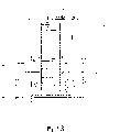
Fig. 3 is the schematic diagram of body display part of the air conditioner of embodiment 1A.
Fig. 4 is the plane of remote controller of the air conditioner of embodiment 1A.
Fig. 5 is the signal controlling party block diagram of the air conditioner of expression embodiment of the invention 1A.
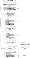
Fig. 6 is the flow chart of the processing carried out of the air conditioner by embodiment of the invention 1A.
Fig. 7 is the signal controlling party block diagram of the air conditioner of expression embodiment of the invention 1B.
Fig. 8 is the flow chart of the processing carried out of the air conditioner by embodiment of the invention 1B.
Fig. 9 is the plane of the remote controller of embodiment of the invention 1B.
Figure 10 is the signal controlling party block diagram of the air conditioner of expression embodiment of the invention 1C.
Figure 11 is the flow chart of the processing carried out of the air conditioner by embodiment of the invention 1C.
Figure 12 is the figure of schematic construction of the air conditioner of the expression embodiment of the invention 2.
Figure 13 and Figure 14 are the mode sectional drawings of humidifying/dehumidifying apparatus of the air conditioner of the expression embodiment of the invention.
The flow chart of Figure 15~Figure 24 operation handoff process that to be expression undertaken by the air conditioner of the embodiment of the invention.
Figure 25 is the perspective view of the outdoor assembly of the air conditioner that is equipped with of embodiment of the invention 3A.
Figure 26 is the plane of the remote controller of embodiment of the invention 3A outfit.
Figure 27 is the profile of internal structure of outdoor assembly of simply representing the air conditioner of embodiment of the invention 3A.
Figure 28 is the profile of internal structure of outdoor assembly of simply representing the air conditioner of embodiment of the invention 3A.
Figure 29 is expression is shown processing procedure by the suggestion of the air conditioner execution of embodiment of the invention 3A a flow chart.
Figure 30 is the figure of the example that shows of the suggestion that shows on the LCD of air conditioner of expression embodiment of the invention 3A.
Figure 31 is the profile of internal structure of outdoor assembly of the air conditioner of reduced representation embodiment of the invention 3B.
Figure 32 is expression is shown processing procedure by the suggestion of the air conditioner execution of embodiment of the invention 3B a flow chart.
Figure 33 and Figure 35 are the figure of the example that shows of the suggestion that shows on the LCD of air conditioner of expression embodiment of the invention 3B.
Figure 34 is the figure of timeliness variation and the threshold value relation of expression indoor temperature.
Figure 36 is the profile of internal structure of outdoor assembly of the air conditioner of reduced representation embodiment of the invention 3C.
Figure 37 is expression is shown processing procedure by the suggestion of the air conditioner execution of embodiment of the invention 3C a flow chart.
Figure 38 and Figure 40 are the figure of the example that shows of the suggestion that shows on the LCD of air conditioner of expression embodiment of the invention 3C.
Figure 39 is the figure of timeliness variation and the threshold value relation of expression room air pollution degree.
Figure 41 is the profile of internal structure of outdoor assembly of the air conditioner of reduced representation embodiment of the invention 3D.
Figure 42 is the profile of internal structure of outdoor assembly of the air conditioner of reduced representation embodiment of the invention 3D.
Figure 43 is expression is shown processing procedure by the suggestion of the air conditioner execution of embodiment of the invention 3D a flow chart.
Figure 44 is the figure of the example that shows of the suggestion that shows on the LCD of air conditioner of expression embodiment of the invention 3D.
Figure 45 is the schematic diagram of the air conditioner of fourth embodiment of the invention.
Figure 46 is the figure of internal structure of indoor assembly body of the air conditioner of expression fourth embodiment of the invention.
Figure 47 is the signal controlling party block diagram of the air conditioner of expression fourth embodiment of the invention.
Figure 48 is a signal controlling party block diagram of representing air conditioner in the past.
Figure 49 is a perspective view of representing the indoor assembly signal outward appearance of air conditioner in the past.
Figure 50 is the decomposition diagram of the LCD that is equipped with on the indoor assembly of in the past air conditioner.
Figure 51 is a controlling party block diagram of representing air-conditioner function in the past.
First embodiment
Below, with reference to the description of drawings embodiments of the invention.Fig. 1 is the schematic diagram of the air conditioner of embodiment of the invention 1A.
(embodiment 1A)
As shown in Figure 1, the air conditioner of embodiment 1A is made of indoor assembly 1, outdoor assembly 2 and remote controller 3.Indoor assembly 1 is made of indoor heat converter 4 and indoor fan 5, and outdoor assembly 2 is made of outdoor heat converter 6, compressor 7, pressure reducer 8, outdoor fan 9.
In addition, in indoor assembly 1, the device that interior dress is made of the adjustable plate 14 of the regenerative heater 12 of the moisture absorption rotor 10 of moisture in absorption or the desorption chamber, the dehumidifying fan 11 that sucks room air, regeneration moisture absorption rotor, the regeneration fan 13 that transmits the air of moisture absorption rotor regeneration, toggle path.
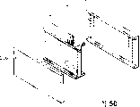
Fig. 2 is the perspective view of the indoor assembly body of air conditioner shown in Figure 1.As shown in Figure 2, indoor assembly 1 is by the body display part 15 that shows operation conditions, constitute the indoor blow-off outlet 16 that blows out warm and cold air, the suction inlet 17 that sucks room air.
Fig. 3 is the schematic diagram of body display part shown in Figure 2.Middle body at indoor assembly 1 has body display part 15.As shown in Figure 3, if pushing ' the notice button ' of remote controller 3, the cleannes lamp 19 of the humidity lamp of being lighted a fire by corresponding indoor humidity in body display part 15 18, respective chamber/chambers internal contamination color change just shows that the display part 20 of indoor environment and operation conditions, reception divide 21 to form from the light accepting part of the signal of remote controller.
Fig. 4 is the plane of remote controller shown in Figure 1.Remote controller 3 shown in Figure 4 sends signal and illuminates by the remote controller displays part 22 that shows running status, to indoor assembly 1 and sends ' moving/stop ' switch 24, the temperature switch 25 of setting indoor temperature that show 23, move/stop air conditioner, makes dehumidifying switch 26 that the dehumidifying operation goes into/cut, makes ventilation switch 27 that the ventilation operation goes into/cut, switches to the formations such as the switch 28 of going out of the operational mode of ventilation when beginning to go out automatically or dehumidifying.
The following describes action.With reference to Fig. 1, when refrigerating operaton, the heat exchange medium that is the condition of high temperature by the compressor condensation is sent in the outdoor heat converter 6 of outdoor assembly 2.In outdoor heat converter 6,, make the heat exchange medium cooling simultaneously with the heat that outdoor fan 9 is removed heat exchange medium by outdoor heat converter 6 extraneous airs.
Heat exchange medium is evaporated in the indoor heat converter 4 of indoor assembly 1 by pressure reducer 8, makes room air remove the heat of room air by indoor heat converter 6 with indoor fan 5.So room air is cooled, can carry out indoor refrigeration.
Indoor heating is opposite with refrigerating operaton, is undertaken by making the opposite circulation of heat exchange medium.In detail, the heat exchange medium of condensation is delivered in the indoor heat converter 4 of indoor assembly 1,, carried out indoor heating by indoor heat converter 4 heating room airs.Heat exchange medium also is evaporated in the outdoor heat converter 6 of outdoor assembly 2 by expansion valve, makes outdoor air pass through outdoor heat converter 6 with outdoor fan 9, after carrying out heat exchange, removes the heat from outdoor air, returns compressor 7.
Then, utilize the dehumidifying of the moisture absorption rotor 10 of zeolite to move with the air in dehumidifying fan 11 suction chambers, through moisture absorption rotor 10, at this moment, the moisture of room air is attracted on the moisture absorption rotor 10, to indoor air of emitting drying.
On the other hand, the moisture of absorption sucks room air with regeneration fan 13 on the moisture absorption rotor 10, heats with regenerative heater 12, after being reached a high temperature, air delivers to moisture absorption rotor 10, at this moment, and the moisture of desorb moisture absorption rotor 10, to the outdoor air that becomes high humidity of emitting, dehumidify to indoor.
In addition, the ventilation operation in the device of the moisture absorption rotor 10 of interior dress zeolite is used when outdoor adjustable plate 14 switches the dehumidifying operation and is blown out to indoor air, with the dehumidifying fan room air is emitted to outdoor.At this moment, moisture absorption rotor 10, regenerative heater 12, regeneration fan 13 are in the OFF state.
The action of the air conditioner of present embodiment is described according to operating procedure below.Air conditioner operate in the operation change-over switch 29 of the control panel of at every turn pushing remote controller 3 time, operational mode is changed into ' automatically '-' heating '-' refrigeration '-' drying '-' automatically ', and be presented on the remote controller displays part 22 of remote controller 3, can select operational mode.
If push ' moving/stop ' switch 24 of the control panel of remote controller 3, order shows operation content, design temperature, indoor temperature on the body display part 15 of indoor assembly 1 so, is in operation, and often shows indoor temperature.
When out of service, if push ' moving/stop ' switch 24 of the control panel of remote controller 3, the demonstration of the body display part 15 of indoor assembly 1 disappears so, and operation stops.
In the time will changing temperature, if push ' △ ', ' ' switch of ' temperature ' switch 25 of the control panel of a remote controller 3, design temperature rises or descends 1 ℃ so, can carry out temperature and set.
In heating or during the heating operation pattern, display setting temperature on the body display part 15 of the remote controller displays part 22 of the control panel of remote controller 3 and indoor assembly 1.
In addition, when automatic or dry operational mode, on the remote controller displays part 22 of the control panel of remote controller 3, only show the temperature section that will rise, display setting temperature on the body display part 15 of indoor assembly 1.
At this moment, the design temperature of the body display part 15 of indoor assembly 1 be presented at about 4 seconds after return room temperature and show.
In the time will changing air quantity, when ' air quantity ' switch 30 of the control panel of at every turn pushing remote controller 3, air quantity changes, on the remote controller displays part 22 of the control panel of remote controller 3, show ' air quantity automatically '-' air quantity △ '-' air quantity △ △ '-' air quantity △ △ △ '-' air quantity is automatic ' shows ' air quantity automatically '-' gentle breeze air quantity '-' weak wind air quantity '-' high wind air quantity '-' air quantity automatically ' on the body display part 15 of indoor assembly 1.
When 5 empty dehumidifying in the device of the moisture absorption rotor 10 of interior dress zeolite operate in ' humidity ' switch 26 of the control panel of at every turn pushing remote controller 3, operational mode is changed into ' dehumidifying '-' humidification '-' stopping '-' dehumidifying ', after selecting ' dehumidifying ' operation, just carry out 5 empty dehumidifying operations.In addition, corresponding with pushing of ' humidity ' switch 26, on the remote controller displays part 22 of the control panel of remote controller 3, switch the empty humidifications ventilation in ' 5 empty dehumidifying '-' 5 '-demonstration of ' do not have and show the empty dehumidifying in '-' 5 ', on the body display part 15 of indoor assembly 1, switch the empty humidifications in ' 5 empty dehumidifying '-' 5 '-demonstration of ' do not have and show the empty dehumidifying in '-' 5 '.
In addition, when the ventilation in the device of the moisture absorption rotor of interior dress zeolite operates in ' ventilation ' switch 27 of the control panel of at every turn pushing remote controller 3, operational mode is changed into ' ventilation automatically '-' ventilation '-' strong ventilation '-' stopping '-' ventilation automatically ', select operational mode, the operation of taking a breath.In addition, corresponding with pushing of ' ventilation ' switch 27, on the remote controller displays part 22 of the control panel of remote controller 3, the empty ventilation in the empty ventilation in '-' 5 '-' 5 is strong automatically to switch ' 5 empty ventilations '-demonstration of ' do not have and show that the empty ventilation in '-' 5 is automatically ', on the body display part 15 of indoor assembly 1, the demonstration of switching ' sensor is taken a breath automatically '-' ventilation continuously '-' strong ventilation '-' nothing shows '-' sensor is taken a breath automatically '.
With reference to Fig. 5 and Fig. 6, when the ventilation in the room of in will going out, closing and dehumidifying, if push ' going out ' switch 28 of the control panel of remote controller 3, on the display part of the control panel of remote controller 3, show so ' ▲ ', show that on the body display part 15 of indoor assembly 1 ' going out ' shows, backlight extinguishing, beginning ' going out ' operation (step S1).
Be in operation, if push ' going out ' switch of the control panel of remote controller 3, so extremely operational mode at that time is cancelled.
In the time will stopping ' going out ' operation, if push ' going out ' switch 28 or ' moving/stop ' switch 24 of the control panel of remote controller 3, the operation of ' going out ' so stops.
Fig. 5 is the controlling party block diagram of the air conditioner function of expression embodiment 1A.
Fig. 6 is the flow chart of the processing carried out of the air conditioner by embodiment 1A.
The humidity sensor 31 that detects indoor humidity is set in the indoor air sucting inlet 17 of indoor assembly 1.The humidity value that humidity sensor 31 detects is input to the humidity decision maker 33 (step S2) of microcomputer 32.In control section 34, the humidity of detection is carried out comparison (step S3).When predefined humidity (for example, humidity 70%) is above, carry out ' 5 empty dehumidifying ' operation (step S4), and when predefined humidity (for example, humidity 70%) is following, carry out ' ventilation ' operation (step S5).Thus, can not have the humid atmosphere in room and make the offending sensation of mood,, can enter salubrious comfortable room yet even return after going out.
The empty dehumidifying of when predefined humidity (for example, humidity 70%) is above ' 5 is arranged again ' operation also can be ' drying ' operation.
(embodiment 1B)
Use Fig. 7, Fig. 8, Fig. 9 that embodiment 1B is described.
Fig. 7 is the controlling party block diagram of the air conditioner function of expression embodiment of the invention 1B.Fig. 8 is the flow chart of the processing carried out of the air conditioner by embodiment of the invention 1B.Fig. 9 is the plane of the remote controller of embodiment of the invention 1B.Remote controller 3 is furnished with the switch of going out 1. 28 and the switch 2. 38 of going out.With reference to Fig. 7, Fig. 8 and Fig. 9, in the air conditioner of embodiment 1B, on indoor air sucting inlet 17, be provided with the humidity sensor 31 that detects indoor humidity.Detect humidity (step S13) with humidity sensor 31.The humidity value that detects is inputed in the humidity decision maker 33 of microcomputer 32, in control section 34, compare (step S14).When being lower than predefined humidity (for example humidity 70%), carry out ' ventilation ' operation (step S19), and be higher than predefined humidity (for example humidity 70%) when above, carry out ' 5 empty dehumidifying ' move.In other words, when predefined humidity (for example humidity 70%) is above, detect (step S15), judge that (step S16) predefined switch of going out is 1. (step S11) or a switch 2. (step S12) of switch.If selector switch is (being YES) 1., carry out ' 5 empty dehumidifying so in step S16 ' operation (step S17), if selector switch 2. (be NO among the step S16) carries out ' drying ' so and moves (step S18).Thus, like utilizing ' 5 empty dehumidifying that regenerative heater carries out moisture absorption rotor regeneration in going out ' though the user of operation pays the high electricity charge, do not have the humid atmosphere in room and make the unhappy sensation of people.
(embodiment 1C)
Figure 10 is the controlling party block diagram of the air conditioner function of expression embodiment of the invention 1C.Figure 11 is the flow chart of the processing carried out of the air conditioner by embodiment of the invention 1C.As Figure 10, shown in Figure 11, the air conditioner of embodiment 1C is furnished with humidity sensor 31 that detects indoor humidity and the temperature sensor 43 that detects indoor temperature on the indoor air sucting inlet 17 of indoor assembly 1.The humidity (step S22) that detects and the value of temperature (step S24) are inputed in the humidity and temperature decision maker 44 of microcomputer 31, in control section 34, compare (step S23, step S25).More than predefined humidity (for example humidity 70%) (being YES among the step S23), during predefined temperature (for example 10 ℃) above (being NO among the step S23), carry out ' drying ' operation 37 (step S27), and below predefined humidity (for example humidity 70%) (being NO among the step S23), preestablish temperature (for example 10 ℃) when above, carry out ' ventilation ' operation 36 (step S28).
In addition, more than predefined humidity (for example humidity 70%) (YES among the step S23), during predefined temperature (for example 10 ℃) following (YES among the step S25), carry out ' 5 empty dehumidifying ' operation 35 (step S26).Thus, do not have the humid atmosphere in room and make the offending sensation of mood, when temperature descends, owing to do not carry out the dehumidifying operation in the compressor, and utilize 5 empty dehumidifying operations of zeolite, so the ability drop that causes because of the frosting of compressor not, dehumidifying effect improves, and comfortableness improves.
As seen from the above description, dress compressor at least, outdoor heat converter, cross valve, the outdoor assembly of outdoor fan, with be furnished with indoor heat converter at least, dress is by the moisture absorption rotor of air moisture in absorption and the desorption chamber in the indoor assembly 1 of indoor fan, the regenerative heater of regeneration moisture absorption rotor, regenerative heater is transmitted in the air conditioner of the device that the regeneration fan of air forms, the present invention is provided with the switch of the operational mode of selecting arrangement, the humidity sensor that utilization is provided with in the suction inlet of described indoor assembly, by the temperature that detects, automatically select dehumidifying operation and ventilation operation, the humidity that the humidity sensor that is provided with on utilizing the suction inlet of described indoor assembly detects is that predefined humidity is when above, operation dehumidifies, and when predefined humidity is following, move by the ventilation operational mode, do not have the humid atmosphere in room and make the offending sensation of mood.
In addition, being provided with humidity and the temperature that the humidity sensor that is provided with in the suction inlet that utilizes described indoor assembly and temperature sensor detect selects to carry out 5 empty dehumidifying operations are still carried out in dry operation by moisture absorption rotor devices by compressor, when humidity that humidity sensor that is provided with in the suction inlet of described indoor assembly and temperature sensor detect and temperature are higher than predefined humidity or are higher than predefined temperature, utilize compressor to carry out the drying operation, and when being lower than predefined humidity or being lower than predefined temperature, utilize moisture absorption rotor to carry out 5 empty dehumidifying operations, do not have the humid atmosphere in room and make the offending sensation of mood, when temperature descends, owing to do not carry out the drying operation of compressor, and utilize 5 empty dehumidifying of zeolite to move, so ability drop that causes because of the frosting of compressor not, dehumidifying effect improves, and comfortableness improves.
Second embodiment
Below, with reference to the description of drawings second embodiment of the present invention.Figure 12 is the schematic configuration diagram of the air conditioner of second embodiment of the invention.As shown in figure 12, air conditioner is furnished with refrigerating circulatory device 101, humidifying/dehumidifying apparatus 102 and controls the control section 103 that their move.Refrigerating circulatory device 101 constitutes the refrigerant loop of airtight binding compressor 104, four-way switching valve 105, outdoor heat converter 106, pressure reducer 107, indoor heat converter 108, and configuration simultaneously promotes the outdoor fan 109 and the indoor fan 110 of the heat exchange of outdoor heat converter 106 and indoor heat converter 108.Have, the arrow among the figure is represented flowing of cold-producing medium again.
Figure 13 is first figure of type section of humidifying/dehumidifying apparatus of the air conditioner of expression present embodiment.
On the other hand, as shown in figure 13, humidifying/dehumidifying apparatus 102 constitutes like this, comprises the moisture absorption rotor 111 of the hygroscopic material that pottery of applying from the teeth outwards by drum shape etc. constitutes; Downstream side branch and outdoor first exhaust pathway 112 that is communicated with and second exhaust pathway 113 at this moisture absorption rotor 111; Make inhaled air pass through moisture absorption rotor 111 after the moisture absorption fan 114 of 112 pairs of outdoor exhausts of first exhaust pathway; Heating is by the heater 115 of the air of the moisture absorption rotor 111 of setting in second exhaust pathway interior 113; With air by making 115 heating of this heater by moisture absorption rotor 111, remove moisture, simultaneously through the regeneration fan 116 of 113 pairs of outdoor exhaust humid air of second exhaust pathway from moisture absorption rotor 111.
Return the explanation of Figure 12.Temperature in indoor temperature transmitter 117 sensing chamber, the humidity in humidity sensor 118 sensing chamber, the temperature outside outdoor temperature sensor 119 sensing chamber, and be connected with the input side of control section 103 respectively.In addition, receiving unit 120 receives the various wireless signals by the operation generation of remote controller 121, and inputs to control section 103.In addition, outlet side at control section 103, be connected with compressor 104 by frequency conversion control circuit (hereinafter referred to as ' inverter circuit '), the fan electromotor 116a of the fan electromotor 114a that is used for moisture absorption rotor motor rotating 111a, moisture absorption fan 114, heater 115 and the regeneration fan 116 of the fan electromotor 109a by relay circuit 123 and four-way switching valve 105, outdoor fan 109, the fan electromotor 110a of indoor fan 110, moisture absorption rotor 111 is connected.Have, indoor fan control circuit 124 is carried out the revolution of indoor fan 110 again.
In such structure, if select refrigeration or dehumidifying operation by the operation of remote controller 121, control section 103 closing relay r2 so switch to four-way switching valve 105 position of dotted line, while closing relay r1 and relay r3, drive chamber's external fan 109 and indoor fan 110.So, inverter circuit 122 actions, compressor 104 brings into operation, and refrigerant gas is transferred into outdoor heat converter 106.This refrigerant gas in outdoor heat converter 106 through with the outdoor air heat exchange liquefaction that is condensed, then in pressure reducer 107, be depressurized afterwards and in indoor heat converter 108, evaporate.At this moment, remove the heat from surrounding air, as cold air, the wind that produces because of indoor fan 110 is to indoor air-supply.And the refrigerant gas of evaporation returns compressor 104 once more, moves to next circulation.By making this a succession of circulation continuously repeatedly, indoor quilt freezes at leisure or dehumidifies.On the other hand, if select heating operation, control section 103 switches to solid line position with four-way switching valve 105 so, heats by the circulation repeatedly opposite with above-mentioned refrigeration or dehumidifying situation.
(embodiment 2A)
The following describes the air conditioner of embodiment of the invention 2A.The flow chart of Figure 15 operation handoff process that to be expression undertaken by the air conditioner of embodiment of the invention 2A.With reference to Figure 15, behind indoor airing washings, remote controller 121 is also selected dry operational mode (step S101).Then, utilize indoor temperature transmitter 117 to detect room temperature, utilize outdoor temperature sensor 119 to detect outside air temperature (step S102).Then, in control section 103, whether the room temperature that judge to detect than for example 21 ℃ low of predefined temperature, and whether the outside air temperature that detects is than predefined temperature for example 18 ℃ low (step S103).Under the situation of affirmative determination, enter step S104, and under the situation of non-affirmative determination, enter step S102.
In step S104, control section 103 switches, and presses heating operation mode operation refrigerating circulatory device 101, switches simultaneously, presses dehumidification mode operation humidifying/dehumidifying apparatus 102.By utilizing control section 103 to make the relay r4~r7 closure of relay circuit 123, what make humidifying/dehumidifying apparatus 102 is used for moisture absorption rotor motor rotating 111a, moisture absorption fan electromotor 114a, heater 115 and regeneration fan motor 116a energising, carries out the switching of operation of the dehumidification mode of humidifying/dehumidifying apparatus 102.
Figure 13 is the mode sectional drawing of expression by the state of dehumidification mode operation humidifying/dehumidifying apparatus 102.With reference to Figure 13, in service at the dehumidification mode of humidifying/dehumidifying apparatus 102 utilizes moisture absorption fan 114 to be taken into indoor air A1 and by moisture absorption rotor 111, at this moment, airborne moisture is adsorbed by moisture absorption rotor 111.By the dry air A2 behind the moisture absorption rotor 111 from 112 pairs of outdoor exhausts of first exhaust pathway.The part of absorption moisture absorption rotor 111 moisture moves to second exhaust pathway, 113 sides by the rotation of moisture absorption rotor 111.
And, also utilize regeneration fan 116 to be taken into a part of room air A3, by moisture absorption rotor 111 and as dry air A4, flow in second exhaust pathway 113 equally.115 heating of this air A4 heater via become high temperature, when passing through moisture absorption rotor 111 from the rear once more, and the moisture of absorption on the desorb moisture absorption rotor 111, and as comprising washy highly humid air A5 from 113 pairs of outdoor emitting of second exhaust pathway.Remove the moisture absorption rotor 111 of regenerating behind the moisture and bring into play wettability power once more by rotation.
Thus, utilize the heating operation of refrigerating circulatory device 101 can promote evaporation, utilize the dehumidifying of humidifying/dehumidifying apparatus 102 to move simultaneously and get rid of indoor moisture, rapidly and efficiently rate ground dry washing material from the moisture of indoor airing washings.
(embodiment 2B)
The following describes the air conditioner of embodiment of the invention 2B.The flow chart of Figure 16 operation handoff process that to be expression undertaken by the air conditioner of embodiment of the invention 2B.With reference to Figure 16, behind indoor airing washings, remote controller 121 is selected dehumidification operating mode (step S111).Then, utilize indoor temperature transmitter 117 to detect room temperature, utilize outdoor temperature sensor 119 to detect outside air temperature (step S112).Then, in control section 103, whether the room temperature that judge to detect than for example 21 ℃ high of predefined temperature, and whether the outside air temperature that detects is than predefined temperature for example 18 ℃ high (step S113).Under the situation of affirmative determination, enter step S114, and under the situation of non-affirmative determination, enter step S112.
In step S114, control section 103 switches, and presses drying mode running refrigerating EGR 101, switches simultaneously, presses dehumidification mode operation humidifying/dehumidifying apparatus 102.By utilizing control section 103 to make the relay r4~r7 closure of relay circuit 123, what make humidifying/dehumidifying apparatus 102 is used for moisture absorption rotor motor rotating 111a, moisture absorption fan electromotor 114a, heater 115 and regeneration fan motor 116a energising, carries out the switching of operation of the dehumidification mode of humidifying/dehumidifying apparatus 102.
Thus, the cooperative effect of utilizing the dehumidifying of the drying operation of refrigerating circulatory device 101 and humidifying/dehumidifying apparatus 102 to move, can promote evaporation from the moisture of indoor airing washings, utilize the dehumidifying of humidifying/dehumidifying apparatus 102 to move simultaneously and get rid of indoor moisture, rapidly and efficiently rate ground dry washing material.
(embodiment 2C)
The following describes the air conditioner of embodiment of the invention 2C.The flow chart of Figure 17 operation handoff process that to be expression undertaken by the air conditioner of embodiment of the invention 2C.With reference to Figure 17, behind indoor airing washings, remote controller 121 is selected dry operational mode (step S121).Then, utilize indoor temperature transmitter 117 to detect room temperature, utilize outdoor temperature sensor 119 to detect outside air temperature (step S122).Then, in control section 103, whether the room temperature that judge to detect than for example 21 ℃ low of predefined temperature, and whether the outside air temperature that detects is than predefined temperature for example 18 ℃ low (step S123).Under the situation of affirmative determination, enter step S124, and under the situation of non-affirmative determination, enter step S122.
In step S124, control section 103 switches, and presses heating operation mode operation refrigerating circulatory device 101, switches simultaneously, by ventilatory pattern operation humidifying/dehumidifying apparatus 102.By utilizing control section 103 to make the relay r5 closure of relay circuit 123, make the moisture absorption fan electromotor 114a energising of humidifying/dehumidifying apparatus 102, carry out the switching of operation of the ventilatory pattern of humidifying/dehumidifying apparatus 102.
Figure 14 is the mode sectional drawing of expression by the state of ventilatory pattern operation humidifying/dehumidifying apparatus 102.With reference to Figure 14, in service in the ventilatory pattern of humidifying/dehumidifying apparatus 102, utilize moisture absorption fan 114 to be taken into indoor air A1, by moisture absorption rotor 111 from 112 pairs of outdoor exhausts of second exhaust pathway (A2).
Thus, utilize the heating operation of refrigerating circulatory device 101 can promote evaporation, utilize the ventilation of humidifying/dehumidifying apparatus 102 to move simultaneously and get rid of indoor moisture, rapidly and efficiently rate ground dry washing material from the moisture of indoor airing washings.
(embodiment 2D)
The following describes the air conditioner of embodiment of the invention 2D.The flow chart of Figure 18 operation handoff process that to be expression undertaken by the air conditioner of embodiment of the invention 2D.With reference to Figure 18, behind indoor airing washings, remote controller 121 is selected dry operational mode (step S131).Then, utilize indoor temperature transmitter 117 to detect room temperature, utilize outdoor temperature sensor 119 to detect outside air temperature (step S132).Then, in control section 103, whether the room temperature that judge to detect than for example 21 ℃ high of predefined temperature, and whether the outside air temperature that detects is than predefined temperature for example 18 ℃ high (step S133).Under the situation of affirmative determination, enter step S134, and under the situation of non-affirmative determination, enter step S132.
In step S134, control section 103 switches, and presses drying mode running refrigerating EGR 101, switches simultaneously, by ventilatory pattern operation humidifying/dehumidifying apparatus 102.By utilizing control section 103 to make the relay r5 closure of relay circuit 123, make the moisture absorption fan electromotor 114a energising of humidifying/dehumidifying apparatus 102, carry out the switching of operation of the ventilatory pattern of humidifying/dehumidifying apparatus 102.
Ventilatory pattern at humidifying/dehumidifying apparatus 102 is in service, utilizes moisture absorption fan 114 to be taken into indoor air A1, by moisture absorption rotor 111 from 112 pairs of outdoor exhausts of second exhaust pathway (A2).
Thus, utilize the cooperative effect of the ventilation operation of the drying operation of refrigerating circulatory device 101 and humidifying/dehumidifying apparatus 102, can promote evaporation, get rid of indoor moisture simultaneously from the moisture of indoor airing washings, rapidly and efficiently rate dry washing material.
(embodiment 2E)
The following describes the air conditioner of embodiment of the invention 2E.The flow chart of Figure 19 operation handoff process that to be expression undertaken by the air conditioner of embodiment of the invention 2E.With reference to Figure 19, behind indoor airing washings, remote controller 121 is selected dry operational mode (step S141).Then, utilize indoor temperature transmitter 117 to detect room temperature, utilize outdoor temperature sensor 119 to detect outside air temperature (step S132).Then, in control section 103, whether the room temperature that judge to detect than for example 21 ℃ low of predefined temperature, and whether the outside air temperature that detects is than predefined temperature for example 18 ℃ low (step S143).Under the situation of affirmative determination, enter step S144, and under the situation of non-affirmative determination, enter step S142.
In step S144, control section 103 switches, and presses heating operation mode operation refrigerating circulatory device 101, switches simultaneously, presses dehumidification mode operation humidifying/dehumidifying apparatus 102.At this moment, pressing preset time (for example 4 hours) dry running time sets and moves.
By utilizing control section 103 to make the relay r4~r7 closure of relay circuit 123, make moisture absorption rotor motor rotating 111a, moisture absorption fan electromotor 114a, heater 115 and the regeneration fan motor 116a energising of humidifying/dehumidifying apparatus 102, carry out the conversion of operation of the dehumidification mode of humidifying/dehumidifying apparatus 102.
At present, under the many situations of the quantity of the washings of indoor airing, for the evaporation from the moisture of washings, do not append indoor dehumidifying, balance is just destroyed, probably can not carry out indoor dehumidifying fully.In this case, indoor humidity becomes all the time than higher state, and the drying efficiency of washings can reduce.
Therefore, judge from the elapsed time that begins dry operational mode whether become the time (step S145) that from predetermined running time (being 4 hours in this case), deducts special time (for example 30 minutes).Entering step S146 through under the situation of this time, do not entering step S144 through under the situation of this time.
In step S146, according to the instruction from control section 103, refrigerating circulatory device 101 switches, by dry operational mode operation.At this moment, the operation of the dehumidification mode of humidifying/dehumidifying apparatus 102 continues.
And, in step S147, judge whether passed through preset time from beginning dry operational mode, under the situation of having passed through the scheduled time, enter step S148, and do not entering step S146 through under the situation of this time.In step S148, stop the operation of the dry operational mode generation of air conditioner.
Thus, can promote dehumidifying, carry out the drying of washings expeditiously from the washings moisture evaporated.
(embodiment 2F)
The following describes the air conditioner of embodiment of the invention 2F.The flow chart of Figure 20 operation handoff process that to be expression undertaken by the air conditioner of embodiment of the invention 2F.With reference to Figure 20, behind indoor airing washings, remote controller 121 is selected dry operational mode (step S151).Then, utilize indoor temperature transmitter 117 to detect room temperature, utilize outdoor temperature sensor 119 to detect outside air temperature (step S152).Then, in control section 103, whether the room temperature that judge to detect than for example 21 ℃ low of predefined temperature, and whether the outside air temperature that detects is than predefined temperature for example 18 ℃ low (step S153).Under the situation of affirmative determination, enter step S154, and under the situation of non-affirmative determination, enter step S142.
In step S154, control section 103 switches, and presses heating operation mode operation refrigerating circulatory device 101, switches simultaneously, presses dehumidification mode operation humidifying/dehumidifying apparatus 102.At this moment, pressing preset time (for example 4 hours) dry running time sets and moves.
By utilizing control section 103 to make the relay r4~r7 closure of relay circuit 123, make moisture absorption rotor motor rotating 111a, moisture absorption fan electromotor 114a, heater 115 and the regeneration fan motor 116a energising of humidifying/dehumidifying apparatus 102, carry out the conversion of operation of the dehumidification mode of humidifying/dehumidifying apparatus 102.
At present, under the many situations of the quantity of the washings of indoor airing, for the evaporation from the moisture of washings, do not append indoor dehumidifying, balance is just destroyed, probably can not carry out indoor dehumidifying fully.In this case, indoor humidity becomes all the time than higher state, and the drying efficiency of washings can reduce.
Therefore, judge from the elapsed time that begins dry operational mode whether become the time (step S155) that from predetermined running time (being 4 hours in this case), deducts special time (for example 30 minutes).Entering step S156 through under the situation of this time, do not entering step S154 through under the situation of this time.
In step S156, according to the instruction from control section 103, refrigerating circulatory device 101 switches, and by dry operational mode operation, simultaneously, humidifying/dehumidifying apparatus 102 switches, by the ventilatory pattern operation.
And, in step S157, judge whether passed through preset time from beginning dry operational mode, under the situation of having passed through the scheduled time, enter step S158, and do not entering step S156 through under the situation of this time.In step S158, stop the operation of the dry operational mode generation of air conditioner.
Thus, can promote from the washings moisture evaporated to carry out the drying of washings expeditiously to outdoor exhaust.
(embodiment 2G)
The following describes the air conditioner of embodiment of the invention 2G.The flow chart of Figure 21 operation handoff process that to be expression undertaken by the air conditioner of embodiment of the invention 2G.With reference to Figure 21, behind indoor airing washings, remote controller 121 is selected dry operational mode (step S161).Then, utilize indoor temperature transmitter 117 to detect room temperature, utilize outdoor temperature sensor 119 to detect outside air temperature (step S162).Then, in control section 103, whether the room temperature that judge to detect than for example 21 ℃ high of predefined temperature, and whether the outside air temperature that detects is than predefined temperature for example 18 ℃ high (step S163).Under the situation of affirmative determination, enter step S164, and under the situation of non-affirmative determination, enter step S162.
In step S164, control section 103 switches, and by dry operational mode running refrigerating EGR 101, switches simultaneously, presses dehumidification mode operation humidifying/dehumidifying apparatus 102.At this moment, pressing preset time (for example 4 hours) dry running time sets and moves.
By utilizing control section 103 to make the relay r4~r7 closure of relay circuit 123, make moisture absorption rotor motor rotating 111a, moisture absorption fan electromotor 114a, heater 115 and the regeneration fan motor 116a energising of humidifying/dehumidifying apparatus 102, carry out the conversion of operation of the dehumidification mode of humidifying/dehumidifying apparatus 102.
At present, under the many situations of the quantity of the washings of indoor airing, for the evaporation from the moisture of washings, do not append indoor dehumidifying, balance is just destroyed, probably can not carry out indoor dehumidifying fully.In this case, indoor humidity becomes all the time than higher state, and the drying efficiency of washings can reduce.
Therefore, judge from the elapsed time that begins dry operational mode whether become the time (step S165) that from predetermined running time (being 4 hours in this case), deducts special time (for example 30 minutes).Entering step S166 through under the situation of this time, do not entering step S164 through under the situation of this time.
In step S166, according to instruction, proceed the operation of the dry operational mode of refrigerating circulatory device 101, and humidifying/dehumidifying apparatus 102 switches, by the ventilatory pattern operation from control section 103.
And, in step S167, judge whether passed through preset time from beginning dry operational mode, under the situation of having passed through the scheduled time, enter step S168, and do not entering step S166 through under the situation of this time.In step S168, stop the operation of the dry operational mode generation of air conditioner.
Thus, can promote from the washings moisture evaporated to carry out the drying of washings expeditiously to outdoor exhaust.
(embodiment 2H)
The following describes the air conditioner of embodiment of the invention 2H.The flow chart of Figure 22 operation handoff process that to be expression undertaken by the air conditioner of embodiment of the invention 2G.With reference to Figure 22, behind indoor airing washings, remote controller 121 is selected dry operational mode (step S171).Then, utilize indoor temperature transmitter 117 to detect room temperature, utilize outdoor temperature sensor 119 to detect outside air temperature (step S172).Then, in control section 103, whether the room temperature that judge to detect than for example 21 ℃ low of predefined temperature, and whether the outside air temperature that detects is than predefined temperature for example 18 ℃ low (step S173).Under the situation of affirmative determination, enter step S174, and under the situation of non-affirmative determination, enter step S172.
In step S174, control section 103 switches, and presses heating operation mode operation refrigerating circulatory device 101, switches simultaneously, presses dehumidification mode operation humidifying/dehumidifying apparatus 102.At this moment, pressing preset time (for example 4 hours) dry running time sets and moves.
By utilizing control section 103 to make the relay r4~r7 closure of relay circuit 123, make moisture absorption rotor motor rotating 111a, moisture absorption fan electromotor 114a, heater 115 and the regeneration fan motor 116a energising of humidifying/dehumidifying apparatus 102, carry out the conversion of operation of the dehumidification mode of humidifying/dehumidifying apparatus 102.
At present, under the many situations of the quantity of the washings of indoor airing, for the evaporation from the moisture of washings, do not append indoor dehumidifying, balance is just destroyed, probably can not carry out indoor dehumidifying fully.In this case, indoor humidity becomes all the time than higher state, and the drying efficiency of washings can reduce.
Therefore, judge from the elapsed time that begins dry operational mode whether become the time (step S175) that from predetermined running time (being 4 hours in this case), deducts special time (for example 30 minutes).Entering step S176 through under the situation of this time, do not entering step S174 through under the situation of this time.
In step S176, according to the instruction from control section 103, refrigerating circulatory device 101 switches, by dry operational mode operation.At this moment, the dehumidification mode operation of humidifying/dehumidifying apparatus 102 is continued.
And, in step S177, judge whether passed through preset time from beginning dry operational mode, under the situation of having passed through the scheduled time, enter step S180, and do not entering step S178 through under the situation of this time.
In step S178, judge whether to stop the compressor 104 of air conditioner.Stopping to enter step S179 under the situation of compressor.Under situation about not stopping, returning step S176.Therefore, at compressor 104 stopping periods, execution in step S179.
In step S179,, press high wind operation indoor fan 110 from control section 103 notice indoor fan control sections 124.At this moment, continue the operation of the dry operational mode of refrigerating circulatory device 101, the operation of the dehumidification mode of humidifying/dehumidifying apparatus 102.
In addition, in step S180, stop the operation of the dry operational mode generation of air conditioner.
Thus,,, help the water evaporates of washings, carry out the initial stage drying of washings by washings is directly touched the high wind that blows out indoor even under the situation that compressor 104 stops.
(embodiment 2I)
The following describes the air conditioner of embodiment of the invention 2I.The flow chart of Figure 23 operation handoff process that to be expression undertaken by the air conditioner of embodiment of the invention 2I.With reference to Figure 23, behind indoor airing washings, remote controller 121 is selected dry operational mode (step S181).Then, utilize indoor temperature transmitter 117 to detect room temperature, utilize outdoor temperature sensor 119 to detect outside air temperature (step S182).Then, in control section 103, whether the room temperature that judge to detect than for example 21 ℃ low of predefined temperature, and whether the outside air temperature that detects is than predefined temperature for example 18 ℃ low (step S183).Under the situation of affirmative determination, enter step S184, and under the situation of non-affirmative determination, enter step S182.
In step S184, judge that whether the humidity that detects is than predefined humidity height, for example whether than 80% height.Under than the high situation of predefined humidity, enter step S185, and under than the low situation of predefined humidity, enter step S186.
In step S185, control section 103 switches, and presses heating operation mode operation refrigerating circulatory device 101, switches simultaneously, by ventilatory pattern operation humidifying/dehumidifying apparatus 102.
On the other hand, in step S186, control section 103 switches, and presses heating operation mode operation refrigerating circulatory device 101, switches simultaneously, presses dehumidification mode operation humidifying/dehumidifying apparatus 102.
Thus, under the high situation of humidity,, can obtain and the identical effect that dehumidifies by comprising washy room air to outdoor exhaust energetically.Under the low situation of humidity, be difficult for the moisture that takes out in moisture absorption rotor 111 absorption and the desorb ventilation by using, the humidity that further descends utilizes the heating operation of refrigerating circulatory device 101 generations can carry out the initial stage drying of washings simultaneously.
(embodiment 2J)
The following describes the air conditioner of embodiment of the invention 2J.The flow chart of Figure 24 operation handoff process that to be expression undertaken by the air conditioner of embodiment of the invention 2J.With reference to Figure 24, behind indoor airing washings, remote controller 121 is selected dry operational mode (step S191).Then, utilize indoor temperature transmitter 117 to detect room temperature, utilize outdoor temperature sensor 119 to detect outside air temperature (step S192).Then, in control section 103, whether the room temperature that judge to detect than for example 21 ℃ high of predefined temperature, and whether the outside air temperature that detects is than predefined temperature for example 18 ℃ high (step S193).Under the situation of affirmative determination, enter step S194, and under the situation of non-affirmative determination, enter step S192.
In step S194, judge that whether the humidity that detects is than predefined humidity height, for example whether than 80% height.Under than the high situation of predefined humidity, enter step S195, and under than the low situation of predefined humidity, enter step S196.
In step S195, control section 103 switches, and presses drying mode running refrigerating EGR 101, switches simultaneously, by ventilatory pattern operation humidifying/dehumidifying apparatus 102.
On the other hand, in step S196, control section 103 switches, and presses drying mode running refrigerating EGR 101, switches simultaneously, presses dehumidification mode operation humidifying/dehumidifying apparatus 102.
Thus, under the high situation of humidity,, can obtain and the identical effect that dehumidifies by comprising washy room air to outdoor exhaust energetically.Under the low situation of humidity, by the moisture that is difficult in 111 absorption of use moisture absorption rotor and the desorb ventilation taking out, the humidity that further descends is utilized the drying operation of refrigerating circulatory device 101 generations simultaneously, can carry out the initial stage drying of washings.
As mentioned above, according to the present invention, owing to use humidifying/dehumidifying apparatus simultaneously and utilize refrigerating circulatory device in heating and dehumidifying, to carry out the drying of washings,, can carry out the drying of washings the short time expeditiously so compare with the independent drying of current refrigerating circulatory device.In addition, even under the situation that compressor stops,, can effectively utilize dry running time owing to utilize humidifying/dehumidifying apparatus can carry out the drying of washings.
The 3rd embodiment
Below, with reference to the description of drawings third embodiment of the present invention.
(embodiment 3A)
Figure 21 represents the major part of the indoor assembly that the air conditioner of embodiment 3A is equipped with, and Figure 31 represents the schematic diagram of LCD.Figure 25 represents the perspective view of the major part of outdoor assembly.Figure 26 represents the plane of the major part of remote controller, the profile of the internal structure of Figure 27 reduced representation indoor assembly, the profile of the internal structure of the outdoor assembly of Figure 28 reduced representation.
Have again, because the structure of the relation of the indoor assembly of present embodiment 3A and remote controller and LCD and homomorphosis in the past, so determine to illustrate with reference to Figure 49 and Figure 50, in addition, attached with same-sign to parts, the part identical with Figure 49 and Figure 50.
The air conditioner of present embodiment 3A is same to be furnished with and to constitute indoor assembly 1 and outdoor assembly 314.This air conditioner also is furnished with the microcomputer (figure omit) of reception from the remote controller 3 continuous indications that send, and moves control.And with reference to Figure 27, the indoor assembly 1 of this moment has the indoor casing 311 that resin etc. is made, and forms air suction inlet 17 in the face side position, and, forming in, lower position adorns the air blow-off outlet 16 of up-down wind direction board 303.In the inside of indoor casing 311, refrigeration and heating machines (omitting among the figure) such as configuration indoor heat converter 318 and indoor fan 319.Have, the symbol A among the figure represents the circulation path of room air again, and symbol B represents wall surface.
In addition, in being furnished with the indoor casing 311 of indoor assembly 1, near configuration humidity sensor 313 air suction inlet 17 that will detect indoor air humidity.
On the other hand, with reference to Fig. 2, above the air blow-off outlet 16 of indoor casing 311, the substantial middle part in indoor casing 311 fronts, configuration can watch displaying contents to form the LCD 15 at angle of inclination slightly downwards easily.I.e. configuration is used to show and the LCD 15 of various information such as operational mode and temperature utilizes this structure, if the user confirms indoor assembly 1 at once, distinguishing some situation when examining at its positive LCD 5 with observing so inevitably.As shown in figure 50, this LCD 15 has such combining structure, the liquid crystal board 306 that comprises display text and symbol etc., it is backlight 307 from its inside illumination liquid crystal board 306 a plurality of LED of liquid crystal display distinctness to be formed, and covers the backlight 307 uniform module cover 308 of illumination light that make incident liquid crystal board 306.Have again, might not there be LCD 15 to be positioned at the top of air blow-off outlet 16, the certainty of the substantial middle part position of the indoor casing 311 of configuration, as long as face side at indoor assembly 1, can certainly be in other position, in addition, have backlight 307 light-emitting component and be not limited to LED, much less, also can be the EL lamp of multiple colour light emitting.
As Figure 25 and shown in Figure 28, outdoor assembly 314 is furnished with the outdoor casing 315 of system such as metal, on three directions of outdoor casing 315, form the air suction inlet 316 of suction chamber outer air, and formation blows out the air blow-off outlet 317 that carries out heat exchange air to other direction in the substantial middle position.In the inside of outdoor casing 315, disposed chamber's outer heat-exchanger 320, compressor, pressure reducer, outdoor fan 321 and in air suction inlet 316, detect the refrigeration and heating machines (omitting among the figure) such as temperature sensor 322 of outdoor temperature.Have, the symbol A among the figure represents the circulation path of outdoor air again.
The following describes the action of the air conditioner of present embodiment 3A.Figure 29 is the flow chart that suggestion that expression is undertaken by the air conditioner of embodiment 3A shows processing procedure.With reference to Figure 29, in the suggestion demonstration is handled, at first, utilize the air humidity in humidity sensor 313 sensing chamber that in indoor assembly 1, dispose, utilize the outside air temperature (step S201) outside outdoor temperature sensor 322 sensing chamber that in outdoor assembly 314, dispose.
Monitor the humidity and the outdoor temperature of room air by microcomputer by humidity sensor 313, outdoor temperature sensor 322.According to the rapid Changes in weather in the operation of air-conditioner, judge whether the humidity of room air and outdoor temperature surpass the humidity (for example being higher than humidity 80%) of predetermined room air and surpass a reference value (step S202) of outdoor temperature (for example being lower than 18 ℃).Under the situation of affirmative determination, enter step S203, under the situation of non-affirmative determination, enter step S201.
In step S203, the demonstration that is configured in the LCD 15 on the indoor casing 311 of indoor assembly 1 is switched to suggestion from common demonstration show.In showing usually, show operating temperature etc., in suggestion shows, show and urge the suggestion of carrying out the ventilation operation meaning.
Figure 30 represents that the suggestion that shows on the LCD 15 of present embodiment 3B shows the figure of an example.With reference to Figure 30, after suggestion was presented at the demonstration of the demonstration that alternately repeats to show ' risings of outside air temperature decline humidity ' respectively during 5 seconds and ' the dry operation of suggestion ', demonstration that at last will ' drying is switched in operation ' showed for 10 seconds.This suggestion shows the change of urging the notice operational mode, shows the button of necessity operation of changing operational mode simultaneously.
Have, if air conditioner stops for operation, though omitted among the figure so, the suggestion of carrying out the demonstration of the demonstration of repetition ' the following humidity of outside air temperature rises ' and ' the dry operation of suggestion ' shows again.
If urge the suggestion of carrying out the dry operation meaning to show that the user can aware the necessity of carrying out dry operation easily so with LCD 15.
Return Figure 29, in step S204, the user who shows by the suggestion of awaring LCD 15 generations indicates dry operation.With reference to Figure 26, utilize ' operation switching push button ' 310a of the action button 310 of pressing remote controller 3 to carry out user's drying operation indication.Thus, provide the indication that requires to carry out the drying operation that compressor produces to indoor assembly 1.
So, carry out the drying operation (step S105) that compressor produces in the air conditioner that is in operation.Thus, move the moisture of removing room air by drying, indoor humidity is descended, indoor comfort level improves.Thus, the convenience of air conditioner increases greatly.
(embodiment 3B)
Figure 31 is the profile of internal structure of the indoor assembly of reduced representation embodiment 3B.Have again, the relation of the indoor assembly of present embodiment 3B, outdoor assembly and remote controller and the structure of LCD and homomorphosis in the past, in addition, because the structure of the major part of indoor assembly is identical with embodiment 3A, so identical mutually separately parts, part to Fig. 2 and Figure 27, Figure 49 and Figure 50 are attached with same-sign, detailed.
With reference to Figure 31, the air conditioner of present embodiment 3B is furnished with and constitutes indoor assembly 1, in being furnished with the indoor casing 311 of this indoor assembly 1, near the humidifying/dehumidifying apparatus 323 that interior dress is used for detecting the humidity sensor that disposes of indoor air humidity air suction inlet 17 and is used to remove room air moisture.And, the humidifying/dehumidifying apparatus 323 of this moment is such devices, form moisture absorption path from air blow-off outlet 16 to the indoor dehumidifying fan 325 that blows out the room air of attraction by the moisture absorption rotor 324 of the moisture absorption raw materials such as zeolite that apply adsorption moisture and by this moisture absorption rotor 324, on the other hand, be furnished with regenerative heater 326 and add hot-air, transmit the air of heating, the regeneration path of the moisture of desorb moisture absorption rotor with 327 pairs of moisture absorption rotors of regeneration fan 324.These devices are that the spy who has formed motion opens the humidifying/dehumidifying apparatus that discloses in flat 8-270980 communique and the flat 10-47706 communique of Te Kai etc.
The following describes the action of the air conditioner of present embodiment 3B.Figure 32 is the flow chart that suggestion that expression is undertaken by the air conditioner of embodiment 3B shows processing procedure.With reference to Figure 32, show in the processing that in suggestion at first, the humidity sensor 313 of utilization configuration in indoor assembly 1 comes the air humidity (step S211) in the sensing chamber.Monitor the humidity of room air by microcomputer by humidity sensor 313.
Whether the humidity of judging the room air in the operation of air-conditioner is lower than predefined humidity (for example being lower than 30%) (step S212).Under the situation of affirmative determination, enter step S213, under the situation of non-affirmative determination, enter step S211.
In step S213, the demonstration that is configured in the LCD 15 on the indoor casing 311 of indoor assembly 1 is switched to suggestion from common demonstration show.In showing usually, show operating temperature etc., in suggestion shows, show and urge the suggestion of carrying out the humidification operation meaning.
Figure 33 represents that the suggestion that shows on the LCD 15 of present embodiment 3B shows first figure of an example.With reference to Figure 33, after suggestion was presented at the demonstration of the demonstration that alternately repeats to show ' just between drying shed ' respectively during 5 seconds and ' suggestion is humidification simultaneously ', demonstration that at last will ' carry out humidification with the humidification button moves ' showed for 10 seconds.This suggestion shows the change of urging the notice operational mode, shows the button of necessity operation of changing operational mode simultaneously.
Have, if air conditioner stops for operation, though omitted among the figure so, the suggestion of carrying out the demonstration of the demonstration of repetition ' just between drying shed ' and ' suggestion is humidification simultaneously ' shows again.
If urge the suggestion of carrying out the humidification operation meaning to show that the user can aware the necessity of carrying out the humidification operation easily so with LCD 15.
Return Figure 32, in step S214, the user who shows by the suggestion of awaring LCD 15 generations indicates the humidification of humidifying/dehumidifying apparatus to move (step S214).With reference to Figure 26, utilize ' humidity button ' 310b of the action button 310 of pressing remote controller 3 to carry out user's drying operation indication.Thus, provide the indication that requires to carry out the humidification operation that humidifying/dehumidifying apparatus produces to indoor assembly 1.
If indoor assembly 1 is provided the indication that requires to carry out the humidification operation, carry out simultaneously the humidification operation that humidifying/dehumidifying apparatus 323 produces in the air conditioner that is in operation so separately, in addition, carry out the humidification operation (step S215) that humidifying/dehumidifying apparatus 323 produces in the air conditioner in operation stops separately.Thus, the moisture of the room air that is attracted by dehumidifying fan 325 is adsorbed by moisture absorption rotor 324, and dry air is emitted outdoor.In addition, the air that heats with regenerative heater 326 utilizes regeneration fan 327 to send moisture absorption rotor 324 to, and the moisture of desorb moisture absorption rotor 324 becomes moistening air and blows out to indoor.Thus, carry out the humidification of room air.
Figure 34 is the figure of time variation and the threshold value relation of expression indoor humidity.As shown in figure 34, the humidity of the room air in operation of air-conditioner reaches predefined humidity B (humidity 30%) when following, carries out the humidification operation that humidifying/dehumidifying apparatus 323 produces, and indoor humidity is improved.Then, the humidity of room air is suitable, compares with humidity B as benchmark, and the humidity of room air rises.
Return Figure 32, in step S216, the humidity sensor 313 of utilization configuration in indoor assembly 1 comes the air humidity in the sensing chamber.Judge that the humidity of the room air in the operation of air-conditioner compares whether rise (step S217) with predefined humidity B.Under situation about judging certainly, enter step S218, under non-situation about judging certainly, enter step S216.
In step S218, the demonstration of the LCD 15 of configuration on the indoor casing 311 of indoor assembly 1 is switched to suggestion from common demonstration show.In suggestion shows, show the suggestion that finishes the humidification operation meaning.
Figure 35 is second figure that the suggestion of LCD 15 demonstrations of expression present embodiment 3B shows an example.With reference to Figure 35, the demonstration of the demonstration that the suggestion demonstration will ' reach comfort humidity ' and ' separating the Humidifying dehumidifying operation ' alternate repetition respectively showed for 5 seconds.This suggestion shows the notice of urging the change operational mode.
If urge the suggestion of separating the Humidifying dehumidifying operation meaning to show that the user can easily aware the necessity of separating the Humidifying dehumidifying operation so with LCD 15.
Return Figure 32, in step S219, by awaring the humidification operation that user that suggestion that LCD 15 produces shows stops humidifying/dehumidifying apparatus.With reference to Figure 26, the operation by remote controller 3 utilize the user humidifying/dehumidifying apparatus the humidification operation stop indication.Thus, stop the humidification operation that humidifying/dehumidifying apparatus produces.Then, in LCD 15, show usually.
(embodiment 3C)
Figure 36 is the profile of internal structure of the indoor assembly of reduced representation embodiment 3C.
Have again, the relation of the indoor assembly of present embodiment 3C, outdoor assembly and remote controller and the structure of LCD and homomorphosis in the past, in addition, because the structure of the major part of indoor assembly is identical with embodiment 3A, so identical mutually separately parts, part to Fig. 2 and Figure 17, Figure 49 and Figure 50 are attached with same-sign, detailed.
With reference to Figure 36, the air conditioner of present embodiment 3C is furnished with the indoor assembly 1 of formation, and this air conditioner receives the indication that sends from remote controller 2, controls operation by microcomputer (omitting among the figure).And, the indoor assembly 1 of this moment has the indoor casing 311 that resin etc. is made, form air suction inlet 17 in the face side position, and, the inside of the indoor casing 311 of the air blow-off outlet 16 of dress up-down wind direction board 303 in lower position forms, refrigeration and heating machines (omitting among the figure) such as configuration indoor heat converter 318 and indoor fan 319.Have, the symbol A among the figure represents the circulation path of room air again, and symbol B represents wall surface.
In being furnished with the indoor casing 311 of indoor assembly 1, near configuration gas sensor 329 air suction inlet 17 that detects the room air dirt.Also be provided with air interchanger to the room air of outdoor discharge dirt.As this air interchanger, applicant of the present invention can use the spy who has formed motion to open the humidifying/dehumidifying apparatus 323 that discloses in flat 8-270980 communique and the flat 10-47706 communique of Te Kai etc.This humidifying/dehumidifying apparatus 323 is by the moisture absorption rotor 324 of moisture absorption raw materials such as zeolite of coating adsorption moisture, and forms moisture absorption paths from air blow-off outlet 16 to the indoor dehumidifying fan 325 that blows out the room air of attraction by this moisture absorption rotor 324.On the other hand, humidifying/dehumidifying apparatus 323 is furnished with regenerative heater 326 and adds hot-air, transmits the air of heating, the regeneration path of the moisture of desorb moisture absorption rotor with 327 pairs of moisture absorption rotors of regeneration fan 324.Utilize the moisture absorption path,, be vented in the outdoor mode, do not use the regeneration path through moisture absorption rotor 324 with the foul atmosphere in dehumidifying fan 325 suction chambers.
In addition, except the scavenging way that utilizes above-mentioned humidifying/dehumidifying apparatus 323, also has the method for eliminating air-polluting aircleaning facility (omitting among the figure) in the clean room of utilizing.This aircleaning facility for example make up cleaning and filtering and by cleaning and filtering the room air that attracts from the air blow-off outlet to the indoor circulating fan that blows out, or use and constitute electric cleaner (omitting among the figure).
On the other hand, partly dispose LCD 15, promptly show the LCD 15 of various information such as operational mode and temperature in the substantial middle of indoor casing 311.As shown in figure 50, this LCD 15 has such combining structure, the liquid crystal board 306 that comprises display text and symbol etc., it is backlight 307 from its inside illumination liquid crystal board 306 a plurality of LED of liquid crystal display distinctness to be formed, and covers the backlight 307 uniform module cover 308 of illumination light that make incident liquid crystal board 306.Have again, might not there be LCD 15 to be positioned at the top of air blow-off outlet 16, the certainty of the substantial middle part position of the indoor casing 311 of configuration, as long as face side at indoor assembly 1, can certainly be in other position, in addition, have backlight 307 light-emitting component and be not limited to LED, much less, also can be the EL lamp of multiple colour light emitting.
The following describes the action of the air conditioner of present embodiment 3C.Figure 37 is the flow chart that suggestion that expression is undertaken by the air conditioner of embodiment 3C shows processing procedure.With reference to Figure 37, show in the processing that in suggestion at first, the gas sensor 329 of utilization configuration in indoor assembly 1 comes the air pollution degree (step S221) in the sensing chamber.Monitor the dustiness of room air by microcomputer by gas sensor 329.
Whether the dustiness of judging the room air in the operation of air-conditioner reaches predefined a reference value (a reference value A of Figure 38) (step S222).Under the situation of affirmative determination, enter step S223, under the situation of non-affirmative determination, enter step S221.
In step S223, the demonstration that is configured in the LCD 15 on the indoor casing 311 of indoor assembly 1 is switched to suggestion from common demonstration show.In showing usually, show operating temperature etc., in suggestion shows, show the suggestion of urging the operation meaning of taking a breath.
Figure 38 represents that the suggestion that shows on the LCD 15 of present embodiment 3C shows first figure of an example.With reference to Figure 38, after suggestion was presented at and alternately repeats during 5 seconds respectively to show the demonstration of the demonstration of ' be used to make air fresh ' and ' suggestion is ventilation automatically ', the demonstration with ' taking a breath with the ventilation button ' at last showed for 10 seconds.This suggestion shows the change of urging the notice operational mode, shows the button of necessity operation of changing operational mode simultaneously.
Have, if air conditioner stops for operation, though omitted among the figure so, the suggestion of carrying out the demonstration of the demonstration of repetition ' be used to make air fresh ' and ' suggestion is ventilation automatically ' shows again.
If urge the suggestion of carrying out the air cleaner operation meaning to show that the user can aware the necessity of carrying out the air cleaner operation easily so with LCD 15.
Return Figure 32, in step S224, the user who shows by the suggestion of awaring LCD 15 generations indicates the automatic ventilation of employing simultaneously to move.With reference to Figure 26, the operation indication of taking a breath automatically when utilizing ' ventilation button ' 310c of the action button 310 press remote controller 3 to carry out according to the user.Thus, the indication that provides requirement to take a breath operation automatically to indoor assembly 1.
If indoor assembly 1 is provided the indication of the operation that requires to take a breath automatically, the ventilation operation operation simultaneously that humidifying/dehumidifying apparatus 323 is produced, in addition, carry out the ventilation operation (step S225) that humidifying/dehumidifying apparatus 323 produces in the air conditioner in operation stops separately.By the operation of taking a breath automatically, dirty room air is excluded outdoor.
Figure 39 is the figure of time variation and threshold value relation of the dustiness of expression room air.As shown in figure 39, when the dustiness of the room air in operation of air-conditioner reaches predefined dustiness A, carry out the automatic ventilation operation that humidifying/dehumidifying apparatus 323 produces, dustiness is descended.Then, the dustiness of room air is disengaged, and the dustiness of room air is descended, and is lower than predetermined dustiness B.
Return Figure 37, in step S226, utilize the gas sensor 329 that in indoor assembly 1, disposes to detect the dustiness of room air.Whether the dustiness of judging the room air in the operation of air-conditioner is than predefined dustiness B little (step S227).Under situation about judging certainly, enter step S228, under non-situation about judging certainly, enter step S226.
In step S228, the demonstration of the LCD 15 of configuration on the indoor casing 311 of indoor assembly 1 is switched to suggestion from common demonstration show.In suggestion shows, show the suggestion that finishes the humidification operation meaning.
Figure 40 is second figure that the suggestion of LCD 15 demonstrations of expression present embodiment 3C shows an example.With reference to Figure 40, the demonstration of the demonstration that the suggestion demonstration will ' reach cleaning ' and ' finishing the ventilation operation ' alternate repetition respectively showed for 5 seconds.This suggestion shows the notice of urging the change operational mode.
If urge the suggestion of removing the operation meaning of taking a breath automatically to show that the user can easily aware the necessity of removing automatic ventilation operation so with LCD 15.
Return Figure 37, in step S229, by awaring the automatic ventilation operation that user that suggestion that LCD 15 produces shows stops humidifying/dehumidifying apparatus.With reference to Figure 26, carry out the indication that stops according to the automatic ventilation operation of user's humidifying/dehumidifying apparatus by the operation of remote controller 3.Thus, stop the automatic ventilation operation that humidifying/dehumidifying apparatus produces.Then, in LCD 15, show usually.
But, self-evident, the microcomputer of the air conditioner of present embodiment 3C has the such operation control function of automatic operational mode, when air conditioner is automatic operational mode, after the suggestion of urging the operation meaning of taking a breath with LCD 15 shows, can adopt the indication of not waiting for according to the user of the operation of taking a breath, begin the structure of the ventilation operation of humidifying/dehumidifying apparatus generation subsequently.And, according to such structure, so owing to needn't bother the user, in the air cleaning operation of automatically taking a breath in case of necessity, so the convenience of air conditioner greatly increases.
(embodiment 3D)
Figure 41 is the profile of internal structure of the indoor assembly of reduced representation embodiment 3D, and Figure 42 is the profile of the internal structure of the outdoor assembly of reduced representation.Have again, the relation of the indoor assembly of present embodiment 3D, outdoor assembly and remote controller and the structure of LCD and homomorphosis in the past, in addition, because the structure of the major part of indoor assembly is identical with embodiment 3A, so identical mutually separately parts, part to Fig. 2, Figure 25, Figure 27, Figure 28, Figure 49 and Figure 50 are attached with same-sign, detailed.
As shown in figure 41, the air conditioner of present embodiment 3D is furnished with the indoor assembly 1 of formation, in being furnished with the indoor casing 311 of this indoor assembly 1, in dress be used to detect the humidity sensor 313 and the indoor temperature transmitter 328 that air suction inlet 17 near, dispose of the humidity and the temperature of room air and the humidifying/dehumidifying apparatus 323 that is used to remove room air moisture.The humidifying/dehumidifying apparatus 323 of this moment by the moisture absorption rotor 324 of moisture absorption raw materials such as zeolite of coating adsorption moisture, and forms moisture absorption path from the air blow-off outlet to the indoor dehumidifying fan 325 that blows out the room air of attraction by this moisture absorption rotor 324.On the other hand, humidifying/dehumidifying apparatus 323 is to be furnished with regenerative heater 326 to add hot-air, transmits the air of heating, the device in the regeneration path of the moisture of desorb moisture absorption rotor with 327 pairs of moisture absorption rotors of regeneration fan 324.These devices are that the spy who has formed motion opens the humidifying/dehumidifying apparatus that discloses in flat 8-270980 communique and the flat 10-47706 communique of Te Kai etc.
As shown in figure 42, outdoor assembly 314 has the outdoor casing 315 that metal etc. is made, on three directions of outdoor casing 315, form the air suction inlet 316 of suction chamber outer air, and on middle position roughly, form the air blow-off outlet 317 that another direction is blown out heat exchange air.Inside at outdoor casing 315.Disposed chamber's outer heat-exchanger 320, compressor, pressure reducer, outdoor fan 321 and in air suction inlet 316, detect the refrigeration and heating machines (omitting among the figure) such as temperature sensor 322 of outdoor temperature.Have, the symbol A among the figure represents the circulation path of outdoor air again.
The following describes the action of the air conditioner of present embodiment 3D.Figure 43 is the flow chart that suggestion that expression is undertaken by the air conditioner of embodiment 3D shows processing procedure.With reference to Figure 43, show in the processing in suggestion, at first, detect the temperature and humidity of room air, outdoor outside air temperature (step S231).The temperature of room air is detected by the indoor temperature transmitter 328 of configuration in the assembly 1, the humidity of air is detected by the humidity sensor 313 of configuration in the assembly 1, and outdoor outside air temperature is detected by the outdoor temperature sensor 322 that disposes in the outdoor assembly 314.
By humidity sensor 313, indoor temperature transmitter and outdoor temperature sensor 322, monitor temperature, humidity and the outdoor temperature of room air by microcomputer.
According to the variation of environment in the operation of air-conditioner, stop the decline that outdoor temperature is predicted in the back in operation, carry out the judgement (step S232) of dewfall prediction with microcomputer.Whether the judgement of dewfall prediction becomes Rob Roy to judge according to following formula (1).
((room temperature+outside air temperature)/2-4)≤((room temperature * temperature (%) * 0.01518)-6.26)
…(1)
Under the situation that formula (1) is set up, be judged as the generation dewfall, enter step S233, under the invalid situation of formula (1), enter step S231.
In step S233, the demonstration that is configured in the LCD 15 on the indoor casing 311 of indoor assembly 1 is switched to suggestion from common demonstration show.In showing usually, show operating temperature etc., in suggestion shows, show the suggestion of urging the operation meaning that dehumidifies.
Figure 44 represents that the suggestion that shows on the LCD 15 of present embodiment 3D shows the figure of an example.With reference to Figure 44, after suggestion was presented at the demonstration of the demonstration that alternately repeats to show ' it feels like generation dewfall ' respectively during 5 seconds and ' advising pre-anti-condensation ', the demonstration with ' dewfall button ' at last showed for 10 seconds.This suggestion shows the change of urging the notice operational mode, shows the button of necessity operation of changing operational mode simultaneously.
Have, if air conditioner stops for operation, though omitted among the figure so, the suggestion of carrying out the demonstration of the demonstration of repetition ' it feels like generation dewfall ' and ' advising pre-anti-condensation ' shows again.
Carry out the air cleaner operation meaning and carry out the suggestion of the button of necessary operation and show that the user can aware the necessity of the operation that dehumidifies easily so if urge in order to change operational mode with LCD 15.
Return Figure 43, in step S234, the user who shows by the suggestion of awaring LCD 15 generations indicates the dehumidifying operation that utilizes humidifying/dehumidifying apparatus.With reference to Figure 26, utilize ' dewfall button ' 310d of the action button 310 press remote controller 3 to carry out indication according to user's the dehumidifying operation that utilizes humidifying/dehumidifying apparatus.Thus, indoor assembly 1 is provided the operation indication of the dehumidifying operation that requires humidifying/dehumidifying apparatus.
If the indication that the dehumidifying operation that provides requirement to utilize humidifying/dehumidifying apparatus 323 to indoor assembly 1 moves, operation simultaneously makes the dehumidifying operation that utilizes humidifying/dehumidifying apparatus 323 in the air conditioner that is in operation so, in addition, utilize the dehumidifying operation (step S135) of humidifying/dehumidifying apparatus 323 in the air conditioner in operation stops separately.Thus, use moisture absorption rotor 324 absorption to utilize the moisture of the room air of dehumidifying fans 325 attractions, to the indoor air that blows out drying, the air of water utilization regenerative heater 326 heating of moisture absorption rotor 324 adsorbs, and blows out outdoor with regeneration fan 327.Its result, the humidity of room air descends, even outdoor temperature descends sharp, the indoor air condition that dewfall does not take place that also is in occurs even outside rapid temperature reduces, and also can prevent dewfall, also prevents mould.
(other embodiment)
But, in each self-structure of the embodiment of above explanation 3A~embodiment 3D, can adopt the various structures below adding.
At first, the first, the suggestion of being undertaken on the LCD 15 by the backlight color different with common demonstration shows.In other words, the common demonstration on the LCD 15 is generally carried out with yellow and green backlight color, but the backlight color when urging the suggestion demonstration of the meanings such as air cleaning operation and ventilation operation is changed into redness.Thus, for example, because that ' switch with operation carry out dry operation ' waits suggestion to be presented on the substrate with custom color different colours is high-visible, so conduct is aroused user's attention easily to the result of the further raising of customer impact.
The second, the demonstration backlight on the LCD 15 also can have the structure of all carrying out until the predefined notice time durations of process.In other words, consider according to experience in the past, owing to think that the suggestion that the user perceives on the LCD 15 shows that the needed time probably is about 5 seconds to 30 seconds, so the time with this scope of also can adopting shows that as suggestion the time of using preestablishes the structure that the suggestion on elimination LCD 15 behind this effluxion shows.In other words, have to prolong the suggestion demonstration of carrying out on the LCD 15 owing to discovering until the user, so in the LCD 15 after perceiveing the certain hour that suggestion shows needed hypothesis, carry out the common demonstration that the relevant suggestion of cancellation shows through the user.Have again,, can consider to make backlight 307 methods of lighting continuously of LCD 15 and the method for flash of light, but under the situation of flash of light, it is just passable about average one time one second that backlight 307 flash period reaches as the method that suggestion shows.
The 3rd, suggestion on the LCD 15 shows the displaying contents that only shows ' information A ' → ' information B ' → ' information A ' → ' information B ' → ' the information C ' as embodiment in certain time repeatedly, but order is that ' information A ' → ' information B ' → ' information C ' → ' information A ' → ' information B ' → ' information A ' is also passable.In addition, the demonstration time is that ' information A ' showed for 5 seconds, and ' information B ' showed for 5 seconds, and ' information C ' showed for 10 seconds, but according to content, ' information A ', ' information B ', ' information C ' can show for 5 seconds, also can show for 10 seconds.Order by making this demonstration and demonstration time change, and obtaining the user, to perceive the method that the suggestion on the LCD 15 shows very important.
The 4th, the suggestion on the LCD 15 be presented at through the notice time by cancellation after, if the user requires to show once more that the structure that shows once more also can be arranged by remote controller 2.And, according to such structure, after suggestion shows cancellation, use a teleswitch and 2 indicate, so owing to carry out suggestion once more with LCD 15 and show, so the user can confirm the suggestion demonstration really if leak user that the suggestion of seeing LCD 15 shows.Have again, customer requirements suggestion show when showing, the state that suggestion shows on the LCD 15 is removed, but situation about having removed according to the state that suggestion shows, because needn't be by the state of User Recognition suggestion demonstration, so much less, the structure of display requirement can be arranged again, the structure of the suggestion demonstration that no longer shows on the LCD 15 also can be arranged.
The 5th, the suggestion on the LCD 15 shows also can have the structure of utilizing sound or voice to report to the police.In other words, during demonstration that carried out the demonstration of various run action of above explanation or alarm generation on LCD 15 environment and machine oneself state changes, for example, also can have the sound and the voice that utilize buzzer, arouse user's attention by the warning of carrying out the suggestion demonstration meaning simultaneously, require the suitably structure of indication.If adopt such structure, can reduce the suggestion of user's miss and show such misgivings.
As mentioned above, the invention is not restricted to motion as air conditioner, self-evident, do not breaking away from the scope of invention, can relate to the commodity of relevant electrified machine such as refrigerator, washing machine, micro-wave oven, heating device.
As described above, according to air conditioner of the present invention, when room air is dirty and the humidity of room air when descending or rising, owing to urge the demonstration of operation ventilation operation and humidification operation or dry operation with LCD, aware the ambient condition that changes at any time easily so observe the user of LCD, according to these states, provide necessary indication really to air conditioner.In addition, owing to the situation after stopping according to operating real daily life status predication, urge the suggestion demonstration of the operation operation meaning with LCD, so make the user relieved, do not have unnecessary worry and driving confusedly,, have the such effect of easy processing for these states.
The 4th embodiment
Below, with reference to the description of drawings fourth embodiment of the present invention.Figure 45 is the schematic diagram of the air conditioner of fourth embodiment of the invention, and Figure 46 is the figure of internal structure of the indoor assembly body of expression present embodiment, and Figure 47 is the signal control chart of the air conditioner of present embodiment.
As shown in figure 45, the air conditioner of fourth embodiment of the invention is made of indoor assembly 1, outdoor assembly 2, remote controller 3.Figure 21 represents the schematic diagram of indoor assembly, and Fig. 4 represents the plane of remote controller 3.Indoor assembly 1 is made of indoor heat converter 404 and indoor fan 405, and outdoor assembly 2 is made of outdoor heat converter 406, compressor 407, pressure reducer 408, outdoor fan 409.
As shown in Figure 2, indoor assembly 1 is made of the body display part 15 of the blow-off outlet 16 that blows out changes in temperature gas, the suction inlet 17 that sucks room air, demonstration operation conditions.
Figure 31 represents the plane of the body display part 15 of indoor assembly 1.Body display part 15 is set at the middle body of indoor assembly 1.With reference to Fig. 3, if this body display part 12 by according to the humidity lamp 18 of indoor humidity igniting, push ' the notice button ' of remote controller according to the cleannes lamp 19 of indoor dirty situation color change and divide 16 to constitute with regard to the display part 20 of environment in the display room and operation conditions, the light accepting part that receives from remote controller signal.
Fig. 4 represents the plane of remote controller 3.With reference to Fig. 4, if remote controller 3 by the remote controller displays part 22 that shows running status to indoor assembly 1 send that transmission that signal just lights shows 23, the operation/shutdown switch 24 of air conditioner, the reset switch 452 when setting the temperature switch 25 of indoor temperature, the battery swap of notice switch 451, remote controller in the time of will knowing operation conditions, the liquid crystal shutter 453 that the light of the liquid crystal of body display part is gone into/cut etc. constitute.
The below action of the air conditioner of explanation present embodiment.
With reference to Figure 45, when refrigerating operaton, be sent to the outdoor heat converter 406 of outdoor assembly 2 by the heat exchange medium of the condition of high temperature of compressor 407 condensations.In outdoor heat converter 406, extraneous gas passes through outdoor heat converter 406 with outdoor fan 409.At this moment, extraneous gas is removed the heat of heat exchange medium, makes the heat exchange medium cooling simultaneously.Then, heat exchange medium is evaporated in the indoor heat converter 404 of indoor assembly 1 by expansion valve 408.At this moment, indoor fan 405 usefulness indoor fans 405 are removed the heat of room air by making room air by indoor heat converter 404.
Like this, room air is cooled, and forms indoor refrigeration.
Indoor heating is opposite with refrigerating operaton, is undertaken by heat exchange medium is circulated on the contrary.
The heat exchange medium of condensation is transferred in the indoor heat converter 404 of indoor assembly 1.Warm by indoor heat converter 404 room airs, carry out indoor heating.
Heat exchange medium also evaporates in the outdoor heat converter 406 of outdoor assembly 2 by pressure reducer 408.Meanwhile, make outdoor air pass through outdoor heat converter 406, carry out heat exchange with indoor fan 405.Thus, heat exchange medium is removed the heat from outdoor air, returns compressor 407.
The following describes operating procedure.
With reference to Fig. 4, during ' operation is switched ' switch 29 of the control panel that the operating in of air conditioner pushed remote controller 3 at every turn, operational mode changes with ' automatically '-' heating '-' refrigeration '-' drying '-' automatically ', and is presented on the remote controller displays part 22 of remote controller 3.Thus, can select operational mode.
If push ' moving/stop ' switch 24 of the control panel of remote controller 3, on the body display part 15 of indoor assembly 1, sequentially show operation content, design temperature, indoor temperature so.In service, usually show indoor temperature.
When out of service, if push ' moving/stop ' switch 24 of the control panel of remote controller 3, but the demonstration of the body display part 15 of decontamination chamber inner assembly 1 so, operation stops.
In the time will changing temperature, in the time of for example will improving 1 ℃, if push ' △ ' switch of ' temperature ' switch 25 of the control panel of a remote controller 3, design temperature rises 1 ℃ so, in heating or during the refrigerating operaton pattern, display setting temperature on the body display part 15 of the remote controller displays part 23 of the control panel of remote controller 3 and indoor assembly 1.
In addition, when automatic or dry operational mode, on the remote controller displays part 23 of the control panel of remote controller 1, only show the temperature that will rise, display setting temperature on the body display part 15 of indoor assembly 1.
At this moment, the design temperature of the body display part 15 of indoor assembly 1 be presented at about 4 seconds after return room temperature and show.
In the time will changing air quantity, whenever push ' air quantity ' switch 30 of the control panel of a remote controller 3, on the remote controller displays part 23 of the control panel of remote controller 3, show ' air quantity is automatic '-' air quantity △ '-' air quantity △ △ '-' air quantity △ △ △ '-' air quantity is automatic ', on the body display part 15 of indoor assembly 1, show ' air quantity is automatic '-' gentle breeze air quantity '-' weak wind air quantity '-' high wind air quantity '-' air quantity is automatic ', air quantity is changed.
The demonstration of the running time of the present invention and the electricity charge, ' moving/stop ' switch 24 operations at the control panel of pushing remote controller 3 stop in back 40 seconds, if push ' notice ' switch 451 of the control panel of remote controller 3, so on the body display part 15 of indoor assembly 1, show ' running time ' of air conditioner, ' electricity charge unit price ' and ' electricity charge ' with the order of ' running time ' → ' electricity charge unit price ' → ' electricity charge '.
For example, show ' 3 hours 30 minutes running time ' → ' calculating ' → ' about 50 yen of electricity charge standard ' by 23 yen/kwh.
' electricity charge unit price ' set by ' 23 yen/kwh ' when dispatching from the factory.Because according to user's region and year, ' electricity charge unit price ' can change, so if push ' emergency operating ' switch 425 (with reference to Figure 46, Figure 47) of indoor assembly 1 body, so variable ' electricity charge unit price ' more than the lasting five seconds.
On the other hand, in remote controller 3, from ' resetting ' switch 452 of the control panel of pushing remote controller 3, it is also passable to continue to push ' liquid crystal ' switch 453 more than 5 seconds.
And, pressing ' liquid crystal ' switch 453, ' △ ' switch of ' temperature ' switch 25 of whenever pushing the control panel of a remote controller 3 can improve 1 yen, can descend 1 yen and push once ' ' switch.After setting ' electricity charge unit price ', unclamp ' liquid crystal ' switch 453, if push ' liquid crystal ' switch 453, the setting of ' electricity charge unit price ' is finished so.
Figure 47 is the air conditioner signal controlling party block diagram of expression the 4th embodiment.With reference to Figure 47, by ' liquid crystal ' switch 453, ' temperature ' switch 25, ' resetting ' switch 452 of remote controller 3, the light accepting part of the body display part 15 of signal inlet chamber inner assembly 1 divides 21.The signal of ' emergency operating ' switch 425 of these signals and indoor assembly 1 body merges, and is input to the switch judgment means 428 of microcomputer 426, judges ' electricity charge unit price ' change.Electricity charge unit price change device 431 with control section 427 changes ' electricity charge unit price '.Measuring device 429 running time with microcomputer 426 comes the running time of instrumentation compressor 407, indoor fan 405 and outdoor fan 409 even loads and consumes electric power with consumption electric power measuring device 430.Energy charge calculation element 432 is calculated the electricity charge, by display circuit, shows the electricity charge on body display part 15.
Thus, even the variation of economic situation takes place,, can correctly show and the corresponding electricity charge of consumption electric power owing to can often change the unit price of the electricity charge.
Electricity charge unit price variation of the present invention is implemented with ' emergency operating ' switch of indoor assembly body and the operation of remote controller switch, but ' emergency operating ' switch that replaces the indoor assembly body with the remote controller switch is arranged, only change the method for electricity charge unit price with remote controller.
In addition, also have on remote controller and indoor assembly body, the unit price change button of electricity charge unit price change is set, change the mode of electricity charge unit price simply.
As seen from the above description, by the outdoor assembly of dress compressor, outdoor heat converter, cross valve, pressure reducer, outdoor fan at least and be furnished with the indoor assembly of indoor heat converter, indoor fan at least and air conditioner that the remote controller of remote-controlled operation operation is formed in, the present invention is provided with the device that change shows the expense unit price of electricity cost on the display part that is provided with on the indoor assembly, utilize the switch of indoor assembly and the switch of remote controller, push certain hour and continue to operate, the expense unit price of electricity cost can be presented on the display part.In addition, even the variation of economic situation takes place, owing to can often change the unit price of electricity cost, so according to the variation of economic situation, can often grasp the electricity charge.Its result can cultivate user's economic concept.
Claims (19)
1. air conditioner, is furnished with the refrigerant loop that links compressor (7), indoor heat converter (4), pressure reducer (8) and outdoor heat converter (6) at least, with the humidifying/dehumidifying apparatus that is used to get rid of indoor moisture (10,11,12,13,14) that is arranged with described refrigerant loop branch, it is characterized in that this air conditioner comprises:
Humidity detector (31), the humidity in the sensing chamber;
Operating portion has the special switch of going out (28); With
Control device (34), at the described special switch of going out (28) when being operated, if the air conditioner cancellation is at that time operation when being in by described refrigerant loop in service, switch in service by described humidifying/dehumidifying apparatus simultaneously, and, from a plurality of operational modes of described humidifying/dehumidifying apparatus, select operational mode according to the humidity that detects by described humidity detector (31);
Described humidifying/dehumidifying apparatus (10,11,12,13,14) in first operational mode (35) with the room air guiding that sucks and the indoor path that is communicated with and with the outdoor path that is communicated with, outside the room air guide chamber with suction in second operational mode (36).
2. air conditioner as claimed in claim 1 is characterized in that, described control device (34) is higher than under the situation of predetermined value in the humidity that described humidity detector (31) detects, and switches to described first operational mode (35).
3. air conditioner as claimed in claim 1 is characterized in that, described control device (34) is lower than under the situation of predetermined value in the humidity that described humidity detector (31) detects, and switches to described second operational mode (36).
4. air conditioner as claimed in claim 1 also is furnished with the temperature-detecting device (43) that detects indoor temperature,
Described control device (34) comprises mode selector (29), the humidity that detects at described humidity detector (31) is higher than under the situation of predetermined moisture, according to the temperature that described temperature-detecting device (43) detects, select not drive the 3rd operational mode (37) of described humidifying/dehumidifying apparatus (10,11,12,13,14) and one of them pattern of described first operational mode (35).
5. air conditioner as claimed in claim 4 is characterized in that, described mode selector (29) is higher than under the situation of predetermined temperature in the temperature that described temperature-detecting device (43) detects, and selects described the 3rd operational mode (37).
6. air conditioner as claimed in claim 4 is characterized in that, described mode selector (29) is lower than under the situation of predetermined temperature in the temperature that described temperature-detecting device (43) detects, and selects described first operational mode (35).
7. air conditioner as claimed in claim 1 is characterized in that,
Wherein air conditioner can drive by the operational mode that drives described refrigerant loop and described humidifying/dehumidifying apparatus (10,11,12,13,14) simultaneously.
8. air conditioner as claimed in claim 7 is characterized in that, described humidifying/dehumidifying apparatus (10,11,12,13,14) comprises the rotatable moisture absorption rotor (111) of moisture in the absorbed air;
The room air that is inhaled into is communicated to first outdoor exhaust pathway (A1, A2) and second exhaust pathway (A3, A4, A5) by at least a portion of described moisture absorption rotor (111); With
What be provided with in the upstream of the described moisture absorption rotor (111) of described second path (A3, A4, A5) is used for heater for heating air (115).
9. air conditioner as claimed in claim 7, described humidifying/dehumidifying apparatus (10,11,12,13,14) can drive by the dehumidification mode that adds hot heater (115) and one of them pattern that does not add the ventilatory pattern of hot heater.
10. air conditioner as claimed in claim 7 is characterized in that also being furnished with:
Detect the temperature sensor (117) of indoor temperature;
Detect the external temperature sensor (119) of outdoor temperature; With
Control the first control device (103) of described four-way switching valve (105), described moisture absorption rotor (111) and described heater (115) respectively,
Described first control device (103) is controlled according to the room temperature of described temperature sensor (117) detection and the outside air temperature of described external temperature sensor (119) detection.
11. air conditioner as claimed in claim 7 is characterized in that also being furnished with:
Detect the temperature sensor (117) of indoor temperature;
Detect the external temperature sensor (119) of outdoor temperature;
Detect the humidity sensor (118) of indoor humidity; With
Control the first control device (103) of described four-way switching valve (105), described moisture absorption rotor (111) and described heater (115) respectively,
The humidity that outside air temperature that the room temperature that described first control device (103) detects according to described temperature sensor (117), described external temperature sensor (119) detect and described humidity sensor (118) detect is controlled.
12. air conditioner as claimed in claim 7 also is furnished with:
Detect the temperature sensor (117) of indoor temperature;
Detect the external temperature sensor (119) of outdoor temperature; With
According to the room temperature of described temperature sensor (117) detection and the outside air temperature of described external temperature sensor (119) detection, switch the second control device of the operational mode of described humidifying/dehumidifying apparatus (10,11,12,13,14).
13. air conditioner as claimed in claim 7 is characterized in that also being furnished with:
Detect the temperature sensor (117) of indoor temperature;
Detect the external temperature sensor (119) of outdoor temperature;
Control the first control device (103) of described four-way switching valve (105), described moisture absorption rotor (111) and described heater (115) respectively; With
Switch the second control device (103) of the operational mode of described humidifying/dehumidifying apparatus (10,11,12,13,14);
Described first control device (103) and described second control device (103) are controlled respectively according to the room temperature of described temperature sensor (117) detection and the outside air temperature of described external temperature sensor (119) detection.
14. air conditioner as claimed in claim 7 is characterized in that also being furnished with:
Control the first control device (103) of described four-way switching valve (105), described moisture absorption rotor (111) and described heater (115) respectively; With
Switch the second control device (103) of the operational mode of described humidifying/dehumidifying apparatus (10,11,12,13,14);
Described first control device is controlled, so that drive described refrigerant loop by the heating operation pattern,, drives by dry operational mode through after the described scheduled time at preset time,
Described second control device is controlled, so that drive described humidifying/dehumidifying apparatus at described preset time by dehumidification mode.
15. air conditioner as claimed in claim 7 is characterized in that being furnished with:
Control the first control device (103) of described four-way switching valve (105), described moisture absorption rotor (111) and described heater (115) respectively; With
Switch the second control device (103) of the operational mode of described humidifying/dehumidifying apparatus (10,11,12,13,14);
Described first control device (103) is controlled, so that drive described refrigerant loop by the heating operation pattern,, drives by dry operational mode through after the described scheduled time at preset time,
Described second control device (103) is controlled, so that drive described humidifying/dehumidifying apparatus at described preset time by described ventilatory pattern.
16. air conditioner as claimed in claim 7 is characterized in that, described second control device is controlled, so that driving described humidifying/dehumidifying apparatus through after the described scheduled time by ventilatory pattern.
17. air conditioner as claimed in claim 7 is characterized in that also being furnished with:
Control the first control device (103) of described four-way switching valve (105), described moisture absorption rotor (111) and described heater (115) respectively; With
Switch the second control device of the operational mode of described humidifying/dehumidifying apparatus (10,11,12,13,14);
Described first control device is controlled, so that drive described refrigerant loop by dry operational mode;
Described second control device is controlled, so that drive described humidifying/dehumidifying apparatus at preset time by described dehumidification mode, through after the described scheduled time, drives by described ventilatory pattern.
18. air conditioner as claimed in claim 7 is characterized in that, described refrigerant loop also comprises the indoor fan (110) to indoor heat converter (4) air-supply room air;
Control the first control device (103) of described indoor fan (110), described four-way switching valve (105), described moisture absorption rotor (111) and described heater (115) respectively; With
Switch the second control device of the operational mode of described humidifying/dehumidifying apparatus (10,11,12,13,14);
Described first control device (103) can drive described indoor fan (110) by high wind and at least two patterns of weak wind;
Press the described refrigerant loop of heating operation mode activated,, control, so that by the described indoor fan of described high wind mode activated (110) at described compressor (7) stopping period;
Described second control device is controlled, so that drive described humidifying/dehumidifying apparatus by described dehumidification mode.
19. air conditioner as claimed in claim 7 is characterized in that also being furnished with:
Detect the temperature sensor (117) of indoor temperature;
Detect the external temperature sensor (119) of outdoor temperature;
Detect the humidity sensor (118) of indoor humidity;
Control the first control device (103) of described four-way switching valve (105), described moisture absorption rotor (111) and described heater (115) respectively; With
Switch the second control device (103) of the operational mode of described humidifying/dehumidifying apparatus (10,11,12,13,14);
The outside air temperature that the room temperature that described first control device (103) detects according to described temperature sensor (117), described external temperature sensor (119) detect is controlled, so that press the described refrigerant loop of one of them mode activated of heating operation pattern and dry operational mode;
Described second control device (103) is controlled, so that the humidity that detects at described humidity sensor (118) is lower than under the situation of predetermined value, drive described humidifying/dehumidifying apparatus (10,11,12,13,14) by described dehumidification mode, be higher than in described humidity under the situation of predetermined value, drive described humidifying/dehumidifying apparatus (10,11,12,13,14) by described ventilatory pattern.
Applications Claiming Priority (11)
| Application Number | Priority Date | Filing Date | Title |
|---|---|---|---|
| JP252624/99 | 1999-09-07 | ||
| JP252624/1999 | 1999-09-07 | ||
| JP25262499A JP2001074295A (en) | 1999-09-07 | 1999-09-07 | Air conditioner |
| JP25262599A JP3604598B2 (en) | 1999-09-07 | 1999-09-07 | Control device for air conditioner |
| JP252625/99 | 1999-09-07 | ||
| JP25262699A JP2001074300A (en) | 1999-09-07 | 1999-09-07 | Air conditioner |
| JP252625/1999 | 1999-09-07 | ||
| JP252626/99 | 1999-09-07 | ||
| JP252626/1999 | 1999-09-07 | ||
| JP10170/00 | 2000-01-14 | ||
| JP2000010170A JP2001201148A (en) | 2000-01-14 | 2000-01-14 | Air conditioner and its drying operation method |
Publications (2)
| Publication Number | Publication Date |
|---|---|
| CN1287250A CN1287250A (en) | 2001-03-14 |
| CN100338401C true CN100338401C (en) | 2007-09-19 |
Family
ID=27478267
Family Applications (1)
| Application Number | Title | Priority Date | Filing Date |
|---|---|---|---|
| CNB001263447A Expired - Fee Related CN100338401C (en) | 1999-09-07 | 2000-09-07 | Air conditioner with functions of dehumidifing and ventilating |
Country Status (3)
| Country | Link |
|---|---|
| EP (1) | EP1083390A3 (en) |
| CN (1) | CN100338401C (en) |
| AU (1) | AU768635B2 (en) |
Families Citing this family (23)
| Publication number | Priority date | Publication date | Assignee | Title |
|---|---|---|---|---|
| CN101650552B (en) * | 2008-08-14 | 2013-08-14 | 海尔集团公司 | System and method for predicting and controlling capability of multi-connection type variable frequency air conditioner |
| KR101447755B1 (en) * | 2008-11-10 | 2014-10-06 | 엘지전자 주식회사 | Indoor unit for air conditioning apparatus |
| ES2498728T3 (en) | 2009-03-27 | 2014-09-25 | Mitsubishi Electric Corporation | Electrostatic atomizer device, appliances, air conditioner and refrigerator |
| KR101595028B1 (en) * | 2009-10-28 | 2016-02-17 | 엘지전자 주식회사 | Air conditioner |
| CN102734900B (en) * | 2011-04-01 | 2014-12-10 | 台达电子工业股份有限公司 | Air-conditioning device having manual dehumidification function and operation method thereof |
| JP6217522B2 (en) * | 2014-05-21 | 2017-10-25 | 株式会社デンソー | Humidifier |
| US10055781B2 (en) | 2015-06-05 | 2018-08-21 | Boveda Inc. | Systems, methods and devices for controlling humidity in a closed environment with automatic and predictive identification, purchase and replacement of optimal humidity controller |
| US10909607B2 (en) | 2015-06-05 | 2021-02-02 | Boveda Inc. | Systems, methods and devices for controlling humidity in a closed environment with automatic and predictive identification, purchase and replacement of optimal humidity controller |
| WO2017083613A1 (en) | 2015-11-12 | 2017-05-18 | Carrier Corporation | Moisture sensing system for heating, ventilation and air conditioning systems |
| JP2017096568A (en) * | 2015-11-25 | 2017-06-01 | ダイキン工業株式会社 | Air conditioner |
| CN105627528A (en) * | 2016-03-30 | 2016-06-01 | 北京博锐尚格节能技术股份有限公司 | Alarm method for cold station group control system |
| DE102017000519A1 (en) * | 2017-01-23 | 2018-07-26 | Donaldson Filtration Deutschland Gmbh | System comprising a device for processing a fluid and a handheld device and method for operating such a system |
| CN107332148A (en) * | 2017-03-01 | 2017-11-07 | 贾海亮 | A kind of humidity automatic detection and regulation box-type substation |
| CN107132857A (en) * | 2017-06-05 | 2017-09-05 | 青岛海尔中央空调有限公司 | A kind of air detecting device control method and air detecting device |
| CN107131565A (en) * | 2017-06-30 | 2017-09-05 | 广东志高暖通设备股份有限公司 | A kind of refrigerating and heating type air conditioner and its indoor set |
| CN110906452B (en) * | 2018-09-18 | 2022-05-31 | 武汉海尔电器股份有限公司 | Air conditioner and control method for air conditioner |
| CN111076380A (en) * | 2018-10-22 | 2020-04-28 | 大金工业株式会社 | Control method of dehumidification system |
| KR102325788B1 (en) * | 2018-12-27 | 2021-11-12 | 주식회사 경동나비엔 | Air conditioner and control method |
| JP7261960B2 (en) * | 2019-08-21 | 2023-04-21 | パナソニックIpマネジメント株式会社 | washing machine |
| CN113899059B (en) * | 2020-06-22 | 2023-10-31 | 大金工业株式会社 | Control method of air treatment system and air treatment system |
| CN216132007U (en) * | 2021-03-22 | 2022-03-25 | 青岛海尔空调电子有限公司 | Device for adjusting humidity |
| CN113405247A (en) * | 2021-05-19 | 2021-09-17 | 青岛海尔空调电子有限公司 | Method and device for controlling humidity regulator and humidity regulator |
| CN113405210B (en) * | 2021-05-19 | 2023-07-18 | 青岛海尔空调电子有限公司 | Control method and device for damping machine and damping machine |
Citations (6)
| Publication number | Priority date | Publication date | Assignee | Title |
|---|---|---|---|---|
| CN2043730U (en) * | 1989-02-21 | 1989-08-30 | 中国建筑科学研究院空气调节研究所 | Revolving wheel dehumidification apparatus |
| JPH0217343A (en) * | 1988-07-06 | 1990-01-22 | Daikin Ind Ltd | Air conditioner |
| JPH06123469A (en) * | 1992-10-08 | 1994-05-06 | Hitachi Ltd | Operation controller for dehumidifying unit with air conditioning and ventilating function |
| JPH08270980A (en) * | 1995-04-03 | 1996-10-18 | Sharp Corp | Air conditioner with dehumidifying and humidifying functions |
| JPH1194316A (en) * | 1997-09-24 | 1999-04-09 | Sharp Corp | Dehumidifier/humidifier |
| JPH11101473A (en) * | 1997-09-30 | 1999-04-13 | Sharp Corp | Humidifier/dehumidifier |
Family Cites Families (21)
| Publication number | Priority date | Publication date | Assignee | Title |
|---|---|---|---|---|
| DE2210473B1 (en) * | 1972-03-04 | 1973-09-06 | Ernst Voetsch Kaelte- Und Klimatechnik Kg, 7462 Frommern | Device for influencing the air humidity in a plant growth chamber with a circulating air system |
| IL64915A (en) * | 1982-02-02 | 1985-04-30 | Joel Harband | Apparatus and method for temperature and humidity control |
| JPS61212313A (en) * | 1985-03-19 | 1986-09-20 | Mitsubishi Heavy Ind Ltd | Dehumidifying device |
| KR900002143B1 (en) * | 1985-03-29 | 1990-04-02 | 미쯔비시 덴끼 가부시기가이샤 | Duct type multizone air-conditioning system |
| JPS62117457A (en) | 1985-11-18 | 1987-05-28 | Ricoh Co Ltd | Facsimile equipment |
| US4916909A (en) * | 1988-12-29 | 1990-04-17 | Electric Power Research Institute | Cool storage supervisory controller |
| EP0414948B1 (en) * | 1989-08-31 | 1992-06-03 | Siemens Aktiengesellschaft | Heating or air conditioning apparatus for an automotive vehicle |
| US4971136A (en) * | 1989-11-28 | 1990-11-20 | Electric Power Research Institute | Dual fuel heat pump controller |
| US5448895A (en) * | 1993-01-08 | 1995-09-12 | Engelhard/Icc | Hybrid heat pump and desiccant space conditioning system and control method |
| JPH08178350A (en) * | 1994-12-28 | 1996-07-12 | Matsushita Electric Ind Co Ltd | Humidity-regulator and air-conditioner provided with humidity-regulating function |
| US5775406A (en) * | 1996-07-01 | 1998-07-07 | Freightliner Corporation | Ventilation message display system and method for a vehicle |
| DE19628735A1 (en) * | 1996-07-17 | 1998-01-22 | Hans Hoffmann | Optimum timing method for air change duration in heated room |
| JP3181525B2 (en) | 1996-12-13 | 2001-07-03 | アルプス電気株式会社 | Spin valve thin film element and thin film magnetic head using the spin valve thin film element |
| US6006142A (en) * | 1997-07-14 | 1999-12-21 | Seem; John E. | Environmental control system and method |
| CA2211746A1 (en) * | 1997-08-19 | 1999-02-19 | Pierre Hosatte | Ventilation controller using outside condition parameters and method to control humidity in buildings and basements |
| JP3767114B2 (en) * | 1997-09-22 | 2006-04-19 | ダイキン工業株式会社 | Air conditioner |
| JPH11101493A (en) | 1997-09-29 | 1999-04-13 | Fujita Corp | Air conditioner and operation control method therefor |
| US5924486A (en) * | 1997-10-29 | 1999-07-20 | Tecom, Inc. | Environmental condition control and energy management system and method |
| KR100285833B1 (en) * | 1998-02-19 | 2001-04-16 | 윤종용 | Air conditioner with metering function and method for controlling operation of air conditioner |
| JP3928679B2 (en) * | 1998-02-27 | 2007-06-13 | 東芝キヤリア株式会社 | Air conditioner |
| JP3646975B2 (en) * | 1998-12-22 | 2005-05-11 | シャープ株式会社 | Air conditioner |
-
2000
- 2000-09-06 EP EP00119509A patent/EP1083390A3/en not_active Withdrawn
- 2000-09-06 AU AU56538/00A patent/AU768635B2/en not_active Ceased
- 2000-09-07 CN CNB001263447A patent/CN100338401C/en not_active Expired - Fee Related
Patent Citations (6)
| Publication number | Priority date | Publication date | Assignee | Title |
|---|---|---|---|---|
| JPH0217343A (en) * | 1988-07-06 | 1990-01-22 | Daikin Ind Ltd | Air conditioner |
| CN2043730U (en) * | 1989-02-21 | 1989-08-30 | 中国建筑科学研究院空气调节研究所 | Revolving wheel dehumidification apparatus |
| JPH06123469A (en) * | 1992-10-08 | 1994-05-06 | Hitachi Ltd | Operation controller for dehumidifying unit with air conditioning and ventilating function |
| JPH08270980A (en) * | 1995-04-03 | 1996-10-18 | Sharp Corp | Air conditioner with dehumidifying and humidifying functions |
| JPH1194316A (en) * | 1997-09-24 | 1999-04-09 | Sharp Corp | Dehumidifier/humidifier |
| JPH11101473A (en) * | 1997-09-30 | 1999-04-13 | Sharp Corp | Humidifier/dehumidifier |
Also Published As
| Publication number | Publication date |
|---|---|
| AU768635B2 (en) | 2003-12-18 |
| EP1083390A3 (en) | 2002-12-04 |
| EP1083390A2 (en) | 2001-03-14 |
| AU5653800A (en) | 2001-03-08 |
| CN1287250A (en) | 2001-03-14 |
Similar Documents
| Publication | Publication Date | Title |
|---|---|---|
| CN100338401C (en) | Air conditioner with functions of dehumidifing and ventilating | |
| CN1158485C (en) | Air conditioner | |
| CN1847737A (en) | Air refining device and ion generator used for the device | |
| CN1541118A (en) | Air refining device and ion generator used for device | |
| CN1179158C (en) | Multiroom air conditioner and control method thereof | |
| CN108980988B (en) | Air conditioner indoor unit and control method of fresh air device thereof | |
| CN1946279A (en) | Temperature controller, processing device, system and method for machine cabinet | |
| CN1299068C (en) | Apparatus and method for controlling operation of louver blades of outdoor unit of air conditioner | |
| CN1176366A (en) | Discharge current control apparatus of air conditioner and method thereof | |
| CN1906445A (en) | Air conditioner | |
| CN1948845A (en) | Air conditioner | |
| CN1948840A (en) | Air conditioner | |
| CN1675504A (en) | Air conditioner | |
| CN1258662C (en) | Air conditioner and temperature detector | |
| CN1942715A (en) | Air conditioner | |
| CN1934393A (en) | Humidity controller | |
| KR20190142280A (en) | Air blower and method of controlling mode thereor | |
| CN1864034A (en) | Air conditioner | |
| CN1930427A (en) | Humidity controller | |
| JP6361667B2 (en) | Air conditioning system | |
| CN1880869A (en) | Air-conditioner | |
| CN1847734A (en) | Indoor unit of air-conditioning system | |
| CN1729374A (en) | An oven for cooking food | |
| CN1527924A (en) | Air conditioning device | |
| CN1788181A (en) | Ion generator and air conditioner |
Legal Events
| Date | Code | Title | Description |
|---|---|---|---|
| C06 | Publication | ||
| PB01 | Publication | ||
| C10 | Entry into substantive examination | ||
| SE01 | Entry into force of request for substantive examination | ||
| C10 | Entry into substantive examination | ||
| SE01 | Entry into force of request for substantive examination | ||
| C14 | Grant of patent or utility model | ||
| GR01 | Patent grant | ||
| CF01 | Termination of patent right due to non-payment of annual fee |
Granted publication date: 20070919 Termination date: 20140907 |
|
| EXPY | Termination of patent right or utility model |