CN100333937C - Motion control of a transporter - Google Patents
Motion control of a transporter Download PDFInfo
- Publication number
- CN100333937C CN100333937C CNB03821668XA CN03821668A CN100333937C CN 100333937 C CN100333937 C CN 100333937C CN B03821668X A CNB03821668X A CN B03821668XA CN 03821668 A CN03821668 A CN 03821668A CN 100333937 C CN100333937 C CN 100333937C
- Authority
- CN
- China
- Prior art keywords
- conveying arrangement
- support platform
- load
- pivoting member
- earth
- Prior art date
- Legal status (The legal status is an assumption and is not a legal conclusion. Google has not performed a legal analysis and makes no representation as to the accuracy of the status listed.)
- Expired - Fee Related
Links
Images


Classifications
-
- B—PERFORMING OPERATIONS; TRANSPORTING
- B62—LAND VEHICLES FOR TRAVELLING OTHERWISE THAN ON RAILS
- B62K—CYCLES; CYCLE FRAMES; CYCLE STEERING DEVICES; RIDER-OPERATED TERMINAL CONTROLS SPECIALLY ADAPTED FOR CYCLES; CYCLE AXLE SUSPENSIONS; CYCLE SIDE-CARS, FORECARS, OR THE LIKE
- B62K17/00—Cycles not otherwise provided for
-
- A—HUMAN NECESSITIES
- A63—SPORTS; GAMES; AMUSEMENTS
- A63C—SKATES; SKIS; ROLLER SKATES; DESIGN OR LAYOUT OF COURTS, RINKS OR THE LIKE
- A63C17/00—Roller skates; Skate-boards
- A63C17/01—Skateboards
-
- A—HUMAN NECESSITIES
- A63—SPORTS; GAMES; AMUSEMENTS
- A63C—SKATES; SKIS; ROLLER SKATES; DESIGN OR LAYOUT OF COURTS, RINKS OR THE LIKE
- A63C17/00—Roller skates; Skate-boards
- A63C17/04—Roller skates; Skate-boards with wheels arranged otherwise than in two pairs
- A63C17/06—Roller skates; Skate-boards with wheels arranged otherwise than in two pairs single-track type
- A63C17/08—Roller skates; Skate-boards with wheels arranged otherwise than in two pairs single-track type single-wheel type with single axis
-
- A—HUMAN NECESSITIES
- A63—SPORTS; GAMES; AMUSEMENTS
- A63C—SKATES; SKIS; ROLLER SKATES; DESIGN OR LAYOUT OF COURTS, RINKS OR THE LIKE
- A63C17/00—Roller skates; Skate-boards
- A63C17/12—Roller skates; Skate-boards with driving mechanisms
-
- B—PERFORMING OPERATIONS; TRANSPORTING
- B60—VEHICLES IN GENERAL
- B60G—VEHICLE SUSPENSION ARRANGEMENTS
- B60G17/00—Resilient suspensions having means for adjusting the spring or vibration-damper characteristics, for regulating the distance between a supporting surface and a sprung part of vehicle or for locking suspension during use to meet varying vehicular or surface conditions, e.g. due to speed or load
- B60G17/015—Resilient suspensions having means for adjusting the spring or vibration-damper characteristics, for regulating the distance between a supporting surface and a sprung part of vehicle or for locking suspension during use to meet varying vehicular or surface conditions, e.g. due to speed or load the regulating means comprising electric or electronic elements
- B60G17/016—Resilient suspensions having means for adjusting the spring or vibration-damper characteristics, for regulating the distance between a supporting surface and a sprung part of vehicle or for locking suspension during use to meet varying vehicular or surface conditions, e.g. due to speed or load the regulating means comprising electric or electronic elements characterised by their responsiveness, when the vehicle is travelling, to specific motion, a specific condition, or driver input
- B60G17/0161—Resilient suspensions having means for adjusting the spring or vibration-damper characteristics, for regulating the distance between a supporting surface and a sprung part of vehicle or for locking suspension during use to meet varying vehicular or surface conditions, e.g. due to speed or load the regulating means comprising electric or electronic elements characterised by their responsiveness, when the vehicle is travelling, to specific motion, a specific condition, or driver input mainly during straight-line motion
-
- B—PERFORMING OPERATIONS; TRANSPORTING
- B60—VEHICLES IN GENERAL
- B60K—ARRANGEMENT OR MOUNTING OF PROPULSION UNITS OR OF TRANSMISSIONS IN VEHICLES; ARRANGEMENT OR MOUNTING OF PLURAL DIVERSE PRIME-MOVERS IN VEHICLES; AUXILIARY DRIVES FOR VEHICLES; INSTRUMENTATION OR DASHBOARDS FOR VEHICLES; ARRANGEMENTS IN CONNECTION WITH COOLING, AIR INTAKE, GAS EXHAUST OR FUEL SUPPLY OF PROPULSION UNITS IN VEHICLES
- B60K26/00—Arrangements or mounting of propulsion unit control devices in vehicles
- B60K26/02—Arrangements or mounting of propulsion unit control devices in vehicles of initiating means or elements
-
- B—PERFORMING OPERATIONS; TRANSPORTING
- B60—VEHICLES IN GENERAL
- B60K—ARRANGEMENT OR MOUNTING OF PROPULSION UNITS OR OF TRANSMISSIONS IN VEHICLES; ARRANGEMENT OR MOUNTING OF PLURAL DIVERSE PRIME-MOVERS IN VEHICLES; AUXILIARY DRIVES FOR VEHICLES; INSTRUMENTATION OR DASHBOARDS FOR VEHICLES; ARRANGEMENTS IN CONNECTION WITH COOLING, AIR INTAKE, GAS EXHAUST OR FUEL SUPPLY OF PROPULSION UNITS IN VEHICLES
- B60K31/00—Vehicle fittings, acting on a single sub-unit only, for automatically controlling vehicle speed, i.e. preventing speed from exceeding an arbitrarily established velocity or maintaining speed at a particular velocity, as selected by the vehicle operator
-
- B—PERFORMING OPERATIONS; TRANSPORTING
- B60—VEHICLES IN GENERAL
- B60Q—ARRANGEMENT OF SIGNALLING OR LIGHTING DEVICES, THE MOUNTING OR SUPPORTING THEREOF OR CIRCUITS THEREFOR, FOR VEHICLES IN GENERAL
- B60Q1/00—Arrangement of optical signalling or lighting devices, the mounting or supporting thereof or circuits therefor
- B60Q1/26—Arrangement of optical signalling or lighting devices, the mounting or supporting thereof or circuits therefor the devices being primarily intended to indicate the vehicle, or parts thereof, or to give signals, to other traffic
-
- B—PERFORMING OPERATIONS; TRANSPORTING
- B62—LAND VEHICLES FOR TRAVELLING OTHERWISE THAN ON RAILS
- B62D—MOTOR VEHICLES; TRAILERS
- B62D1/00—Steering controls, i.e. means for initiating a change of direction of the vehicle
- B62D1/02—Steering controls, i.e. means for initiating a change of direction of the vehicle vehicle-mounted
- B62D1/12—Hand levers
-
- B—PERFORMING OPERATIONS; TRANSPORTING
- B62—LAND VEHICLES FOR TRAVELLING OTHERWISE THAN ON RAILS
- B62D—MOTOR VEHICLES; TRAILERS
- B62D51/00—Motor vehicles characterised by the driver not being seated
- B62D51/02—Motor vehicles characterised by the driver not being seated the driver standing in the vehicle
-
- B—PERFORMING OPERATIONS; TRANSPORTING
- B62—LAND VEHICLES FOR TRAVELLING OTHERWISE THAN ON RAILS
- B62K—CYCLES; CYCLE FRAMES; CYCLE STEERING DEVICES; RIDER-OPERATED TERMINAL CONTROLS SPECIALLY ADAPTED FOR CYCLES; CYCLE AXLE SUSPENSIONS; CYCLE SIDE-CARS, FORECARS, OR THE LIKE
- B62K11/00—Motorcycles, engine-assisted cycles or motor scooters with one or two wheels
- B62K11/007—Automatic balancing machines with single main ground engaging wheel or coaxial wheels supporting a rider
-
- B—PERFORMING OPERATIONS; TRANSPORTING
- B62—LAND VEHICLES FOR TRAVELLING OTHERWISE THAN ON RAILS
- B62M—RIDER PROPULSION OF WHEELED VEHICLES OR SLEDGES; POWERED PROPULSION OF SLEDGES OR SINGLE-TRACK CYCLES; TRANSMISSIONS SPECIALLY ADAPTED FOR SUCH VEHICLES
- B62M7/00—Motorcycles characterised by position of motor or engine
-
- A—HUMAN NECESSITIES
- A63—SPORTS; GAMES; AMUSEMENTS
- A63C—SKATES; SKIS; ROLLER SKATES; DESIGN OR LAYOUT OF COURTS, RINKS OR THE LIKE
- A63C2203/00—Special features of skates, skis, roller-skates, snowboards and courts
- A63C2203/52—Direct actuation of steering of roller skate or skateboards, e.g. by a foot plate
-
- B—PERFORMING OPERATIONS; TRANSPORTING
- B60—VEHICLES IN GENERAL
- B60G—VEHICLE SUSPENSION ARRANGEMENTS
- B60G2300/00—Indexing codes relating to the type of vehicle
- B60G2300/12—Cycles; Motorcycles
-
- B—PERFORMING OPERATIONS; TRANSPORTING
- B60—VEHICLES IN GENERAL
- B60G—VEHICLE SUSPENSION ARRANGEMENTS
- B60G2300/00—Indexing codes relating to the type of vehicle
- B60G2300/20—Toys
-
- B—PERFORMING OPERATIONS; TRANSPORTING
- B60—VEHICLES IN GENERAL
- B60G—VEHICLE SUSPENSION ARRANGEMENTS
- B60G2300/00—Indexing codes relating to the type of vehicle
- B60G2300/22—Perambulators
-
- B—PERFORMING OPERATIONS; TRANSPORTING
- B60—VEHICLES IN GENERAL
- B60G—VEHICLE SUSPENSION ARRANGEMENTS
- B60G2300/00—Indexing codes relating to the type of vehicle
- B60G2300/26—Carts
-
- B—PERFORMING OPERATIONS; TRANSPORTING
- B60—VEHICLES IN GENERAL
- B60G—VEHICLE SUSPENSION ARRANGEMENTS
- B60G2400/00—Indexing codes relating to detected, measured or calculated conditions or factors
- B60G2400/05—Attitude
- B60G2400/051—Angle
- B60G2400/0512—Pitch angle
-
- B—PERFORMING OPERATIONS; TRANSPORTING
- B60—VEHICLES IN GENERAL
- B60G—VEHICLE SUSPENSION ARRANGEMENTS
- B60G2400/00—Indexing codes relating to detected, measured or calculated conditions or factors
- B60G2400/60—Load
- B60G2400/61—Load distribution
-
- B—PERFORMING OPERATIONS; TRANSPORTING
- B60—VEHICLES IN GENERAL
- B60G—VEHICLE SUSPENSION ARRANGEMENTS
- B60G2400/00—Indexing codes relating to detected, measured or calculated conditions or factors
- B60G2400/60—Load
- B60G2400/63—Location of the center of gravity
-
- B—PERFORMING OPERATIONS; TRANSPORTING
- B60—VEHICLES IN GENERAL
- B60G—VEHICLE SUSPENSION ARRANGEMENTS
- B60G2500/00—Indexing codes relating to the regulated action or device
- B60G2500/40—Steering
-
- B—PERFORMING OPERATIONS; TRANSPORTING
- B60—VEHICLES IN GENERAL
- B60G—VEHICLE SUSPENSION ARRANGEMENTS
- B60G2800/00—Indexing codes relating to the type of movement or to the condition of the vehicle and to the end result to be achieved by the control action
- B60G2800/01—Attitude or posture control
- B60G2800/014—Pitch; Nose dive
-
- B—PERFORMING OPERATIONS; TRANSPORTING
- B60—VEHICLES IN GENERAL
- B60G—VEHICLE SUSPENSION ARRANGEMENTS
- B60G2800/00—Indexing codes relating to the type of movement or to the condition of the vehicle and to the end result to be achieved by the control action
- B60G2800/01—Attitude or posture control
- B60G2800/019—Inclination due to load distribution or road gradient
- B60G2800/0192—Inclination due to load distribution or road gradient longitudinal with regard to vehicle
-
- B—PERFORMING OPERATIONS; TRANSPORTING
- B60—VEHICLES IN GENERAL
- B60G—VEHICLE SUSPENSION ARRANGEMENTS
- B60G2800/00—Indexing codes relating to the type of movement or to the condition of the vehicle and to the end result to be achieved by the control action
- B60G2800/90—System Controller type
- B60G2800/91—Suspension Control
- B60G2800/912—Attitude Control; levelling control
-
- B—PERFORMING OPERATIONS; TRANSPORTING
- B60—VEHICLES IN GENERAL
- B60G—VEHICLE SUSPENSION ARRANGEMENTS
- B60G2800/00—Indexing codes relating to the type of movement or to the condition of the vehicle and to the end result to be achieved by the control action
- B60G2800/90—System Controller type
- B60G2800/91—Suspension Control
- B60G2800/915—Suspension load distribution
-
- B—PERFORMING OPERATIONS; TRANSPORTING
- B60—VEHICLES IN GENERAL
- B60L—PROPULSION OF ELECTRICALLY-PROPELLED VEHICLES; SUPPLYING ELECTRIC POWER FOR AUXILIARY EQUIPMENT OF ELECTRICALLY-PROPELLED VEHICLES; ELECTRODYNAMIC BRAKE SYSTEMS FOR VEHICLES IN GENERAL; MAGNETIC SUSPENSION OR LEVITATION FOR VEHICLES; MONITORING OPERATING VARIABLES OF ELECTRICALLY-PROPELLED VEHICLES; ELECTRIC SAFETY DEVICES FOR ELECTRICALLY-PROPELLED VEHICLES
- B60L2200/00—Type of vehicles
- B60L2200/16—Single-axle vehicles
-
- B—PERFORMING OPERATIONS; TRANSPORTING
- B60—VEHICLES IN GENERAL
- B60L—PROPULSION OF ELECTRICALLY-PROPELLED VEHICLES; SUPPLYING ELECTRIC POWER FOR AUXILIARY EQUIPMENT OF ELECTRICALLY-PROPELLED VEHICLES; ELECTRODYNAMIC BRAKE SYSTEMS FOR VEHICLES IN GENERAL; MAGNETIC SUSPENSION OR LEVITATION FOR VEHICLES; MONITORING OPERATING VARIABLES OF ELECTRICALLY-PROPELLED VEHICLES; ELECTRIC SAFETY DEVICES FOR ELECTRICALLY-PROPELLED VEHICLES
- B60L2200/00—Type of vehicles
- B60L2200/24—Personal mobility vehicles
-
- B—PERFORMING OPERATIONS; TRANSPORTING
- B60—VEHICLES IN GENERAL
- B60L—PROPULSION OF ELECTRICALLY-PROPELLED VEHICLES; SUPPLYING ELECTRIC POWER FOR AUXILIARY EQUIPMENT OF ELECTRICALLY-PROPELLED VEHICLES; ELECTRODYNAMIC BRAKE SYSTEMS FOR VEHICLES IN GENERAL; MAGNETIC SUSPENSION OR LEVITATION FOR VEHICLES; MONITORING OPERATING VARIABLES OF ELECTRICALLY-PROPELLED VEHICLES; ELECTRIC SAFETY DEVICES FOR ELECTRICALLY-PROPELLED VEHICLES
- B60L2220/00—Electrical machine types; Structures or applications thereof
- B60L2220/10—Electrical machine types
- B60L2220/30—Universal machines
-
- B—PERFORMING OPERATIONS; TRANSPORTING
- B60—VEHICLES IN GENERAL
- B60L—PROPULSION OF ELECTRICALLY-PROPELLED VEHICLES; SUPPLYING ELECTRIC POWER FOR AUXILIARY EQUIPMENT OF ELECTRICALLY-PROPELLED VEHICLES; ELECTRODYNAMIC BRAKE SYSTEMS FOR VEHICLES IN GENERAL; MAGNETIC SUSPENSION OR LEVITATION FOR VEHICLES; MONITORING OPERATING VARIABLES OF ELECTRICALLY-PROPELLED VEHICLES; ELECTRIC SAFETY DEVICES FOR ELECTRICALLY-PROPELLED VEHICLES
- B60L2260/00—Operating Modes
- B60L2260/20—Drive modes; Transition between modes
- B60L2260/34—Stabilising upright position of vehicles, e.g. of single axle vehicles
-
- Y—GENERAL TAGGING OF NEW TECHNOLOGICAL DEVELOPMENTS; GENERAL TAGGING OF CROSS-SECTIONAL TECHNOLOGIES SPANNING OVER SEVERAL SECTIONS OF THE IPC; TECHNICAL SUBJECTS COVERED BY FORMER USPC CROSS-REFERENCE ART COLLECTIONS [XRACs] AND DIGESTS
- Y10—TECHNICAL SUBJECTS COVERED BY FORMER USPC
- Y10S—TECHNICAL SUBJECTS COVERED BY FORMER USPC CROSS-REFERENCE ART COLLECTIONS [XRACs] AND DIGESTS
- Y10S180/00—Motor vehicles
- Y10S180/907—Motorized wheelchairs
-
- Y—GENERAL TAGGING OF NEW TECHNOLOGICAL DEVELOPMENTS; GENERAL TAGGING OF CROSS-SECTIONAL TECHNOLOGIES SPANNING OVER SEVERAL SECTIONS OF THE IPC; TECHNICAL SUBJECTS COVERED BY FORMER USPC CROSS-REFERENCE ART COLLECTIONS [XRACs] AND DIGESTS
- Y10—TECHNICAL SUBJECTS COVERED BY FORMER USPC
- Y10S—TECHNICAL SUBJECTS COVERED BY FORMER USPC CROSS-REFERENCE ART COLLECTIONS [XRACs] AND DIGESTS
- Y10S180/00—Motor vehicles
- Y10S180/908—Motor vehicles with short wheelbase
Abstract
A transporter for transporting a subject over a surface that may be irregular. The transporter includes a support platform for supporting a load, the loaded support platform defining fore-aft and lateral planes and characterized by a load distribution. A plurality of ground contacting elements are coupled to the support platform. At least one of the plurality of ground contacting elements is driven by a motorized drive arrangement. A sensor module generates a signal indicative of the load distribution of the loaded support platform. Based at least on the load distribution, a controller commands the motorized drive arrangement.
Description
Technical field
The present invention relates to a kind of conveying arrangement and method that is used for load transported, this load can be human body, more particularly, the present invention relates to the motion control of conveying arrangement.
Background technology
Known many vehicles with motorized drive arrangement are used to carry various objects, or in order on purpose to move or for amusement.The device that operating personal is used for controlling the motorized drive arrangement motion is varied.For example, operating personal can be handled Das Gaspedal and come the forward direction of Control of Automobile to move, and utilizes bearing circle to realize driving simultaneously usually.Perhaps can control moving of entertainment type vehicle by shaking pedal forward or backward, wherein the user stands on this pedal, and (throttle cable) mechanically moves so that throttle gate is just restricted, and as US Patent NO.4,790,548 (Francken) are described.For example, based on the fitness of operating personal, or the expectation function of conveying arrangement, wish to obtain a kind of other method of controlling the conveying arrangement motion.
Summary of the invention
In the first embodiment of the present invention, a kind of conveying arrangement is provided, it comprises the support platform that is used for bearing load, loaded support platform has longitudinal plane and Transverse plane and is characterized by distribution of load.Described conveying arrangement is statically stable with regard to plane inclination along the longitudinal thereby a plurality of elements that contact to earth are connected with support platform.In a plurality of elements that contact to earth at least one driven by motorized drive arrangement.Sensor assembly produces the signal of the distribution of load state of indication loaded support platform.Controller is controlled motorized drive arrangement based on distribution of load at least.
According to related embodiments of the invention, a plurality of element that contacts to earth comprises at least two wheels.Described at least two wheels comprise can be around first wheel and second wheel that can center on second rotation, second back that is positioned at primary shaft of primary shaft rotation.Controller can be configured to control by distribution of load that longitudinally changes loaded support platform and/or center-of-gravity position the longitudinal movement of conveying arrangement.This controller also can be configured to laterally change the distribution of load of loaded support platform and/or the cross motion that center-of-gravity position is controlled conveying arrangement by the edge.Conveying arrangement can comprise the user interface such as joystick and calibrated disc, and wherein this controller is controlled motorized drive arrangement based on a signal that is provided by user interface at least.Sensor assembly can comprise force gauge, load transducer and/or the angular rate sensor such as inclination sensor, and this inclination sensor for example can be gyroscope or incline level.When producing signal, can use side-play amount.This side-play amount can be regulated by the user interface on conveying arrangement or the remote control equipment (RCE).Thereby controller may command motorized drive arrangement impels this conveying arrangement to quicken.Conveying arrangement also can comprise and can be used for providing indication based on the motion such as quickening from the indicating device of visual observation.Described indicating device can be an indicator lamp, and is visual from the conveying arrangement back.
According to another embodiment of the invention, proposed a kind of method of controlling conveying arrangement, this conveying arrangement has the support platform of bearing load.Loaded support platform has longitudinal plane and Transverse plane and is characterized by distribution of load.Conveying arrangement comprises a plurality of elements that contact to earth, thereby this conveying arrangement is statically stable with regard to plane inclination along the longitudinal, wherein at least one in a plurality of elements that contact to earth of motorized drive arrangement.Described method comprises the distribution of load of determining loaded support platform, controls motorized drive arrangement based on distribution of load at least.
According to still another embodiment of the invention, conveying arrangement comprises the support platform of bearing load, and this support platform has longitudinal plane and Transverse plane.This support platform is statically stable with regard to plane and Transverse plane tilt along the longitudinal thereby a plurality of elements that contact to earth are connected with support platform.Thereby pivoting member is connected this pivoting member pivotally with one of them element that contacts to earth can tilt by user interface.Sensor assembly produces and shows pivoting member bevelled signal.Controller is controlled motorized drive arrangement based on the inclination of pivoting member.In a plurality of elements that contact to earth of motorized drive arrangement at least one.
In the embodiment that the present invention is correlated with, pivoting member is plane inclination at least longitudinally.A plurality of elements that contact to earth can comprise the wheel of Wei Rao the axle rotation of two horizontally sets, and pivoting member is connected pivotally with this axle.Pivoting member via at least one spring for example can with the support platform flexible-disc joint.User interface can be and pivoting member bonded assembly handle.
According to another embodiment of the invention, a kind of method of controlling conveying arrangement has the support platform of bearing load, and this support platform has longitudinal plane and Transverse plane.Conveying arrangement comprises a plurality of elements that contact to earth, thereby this conveying arrangement is statically stable with regard to inclination.Conveying arrangement also comprises and one of them element bonded assembly pivoting member pivotally of contacting to earth, thereby this pivoting member can tilt, at least one in a plurality of elements that contact to earth of motorized drive arrangement.Described method comprises makes pivoting member inclination and control motorized drive arrangement as its tilt function.
Brief description of drawings
With reference to accompanying drawing and with reference to following detailed, above-mentioned feature of the present invention will be easier to understand, wherein:
Fig. 1 is the lateral plan of conveying arrangement according to an embodiment of the invention;
Fig. 2 (a) is the lateral plan of conveying arrangement according to an embodiment of the invention;
Fig. 2 (b) is the lateral plan of conveying arrangement according to an embodiment of the invention;
Fig. 3 is the lateral plan of dynamic equilibrium vehicle;
Fig. 4 for according to one embodiment of present invention, be used to control the controller block diagram of the motorized drive of conveying arrangement;
Fig. 5 is a conveying arrangement according to an embodiment of the invention.
The specific embodiment mode
According to one embodiment of present invention, Fig. 1 shows a kind of conveying arrangement 10 that is used for other the surperficial upper support load on ground or such as the floor, described load can be lived object, and described ground or other surface are called " ground " here.Conveying arrangement 10 comprises the support platform 11 of bearing load.For example, object can stand in or be shelved on the support platform 11.What link to each other with support platform 11 is handle 12, can hold this handle 12 when operation conveying arrangement 10.
What be connected with support platform 11 is a plurality of elements 13,14 that contact to earth, and they provide contacting between support platform 11 and the ground.The element that contacts to earth can include, but not limited to arc part, track, tyre surface and wheel (the following term " wheel " that will use refers to any this unrestricted element that contacts to earth) in specification sheets.Wheel 13,14 helps to limit many axis, and these axis comprise vertical axis Z-Z, and it is along gravity direction process wheel and ground-surface contact point; Axis of pitch Y-Y, it is parallel to the axle of wheel; Longitudinal axis X-X, it is perpendicular to axletree.The direction parallel with Y-Y with axis X-X is called vertical and horizontal.
Conveying arrangement 10 at least on longitudinal plane with regard to inclination and along being statically stable.In order to obtain statical stability on longitudinal plane, conveying arrangement 10 can comprise first and second wheels 13,14 at least.First wheel 13 can be around the primary shaft rotation, and second wheel 14 can be around second rotation of primary shaft back, and the center of gravity of conveying arrangement 10 is between first and second wheels like this.
Control the motion of conveying arrangement 10 by the center of gravity that changes loaded support platform.It being understood that employed " center-of-gravity position " is the instantaneous example of distribution of load here.Any mechanism that controls the motion of described device according to distribution of load drops in the scope of the present invention as described herein and in all subsidiary any claims.The change of center-of-gravity position for example can realize by its weight on support platform 11 of movement of objects.In order to determine moving of center of gravity, conveying arrangement 10 comprises sensor assembly.This sensor assembly produces a signal, and the center of gravity of expression loaded support platform is with respect to the position of bench mark on the conveying arrangement 10.
Sensor assembly comprises at least one sensor.This at least one sensor can be, but is not limited to, and load transducer, force gauge and/or angular rate sensor for example can be the inclination sensors of gyroscope or clinometer and so on.
With reference to Fig. 1, for example, conveying arrangement 10 comprises two load transducers 15,16.Load transducer 15 is connected between the support platform 11 and first wheel 13, and load transducer 16 is connected between the support platform 11 and second wheel 14.Utilize the load on each wheel 13 and 14 detected, can be with respect to for example along the center-of-gravity position of conveying arrangement 10 longitudinal axis, but be not limited to, the bench mark of platform 11 front ends calculates.In various embodiments, can adopt the mono-load transducer.For example, if the weight of known load support platform so only adopts a load transducer just can determine center of gravity.The variation that the output of load transducer produces owing to the center of gravity that changes loaded support platform also can be used to control the motion of conveying arrangement 10.
Fig. 2 (a) shows another kind of conveying arrangement 20 according to an embodiment of the invention.This conveying arrangement 20 comprises support platform 21, and this support platform can tilt at longitudinal plane based on for example center of gravity of this platform 21, is still simultaneously statically stable at least with regard to plane inclination along the longitudinal.For example, but be not limited to, a pair of spring 26 and 25 can be connected to wheel 23 and 24 and support platform 21 between.In other embodiments, the element 23 and 24 that contacts to earth can have that some are flexible and have a function of spring.According to the inclination of support platform 21 on longitudinal plane, have at least a sensor 27 to produce a signal, show for example position of loaded support platform center of gravity.Sensor 27 can be, but be not limited to: spring and relevant sensor (for example rang sensor); Load transducer; The inclination sensor that support platform 21 degree of dip are provided such as incline level or gyroscope; Whisker (whiskers); Angular rate sensor; And/or the noncontacting proximity sensor such as super sonic or optics.Can measure the inclination angle with respect to the bench mark (being not limited to these) near the position S. A. on gravity, ground and/or the conveying arrangement.What link to each other with support platform 21 can be handle 22, can hold this handle 22 when operation conveying arrangement 20.
In another embodiment of the present invention, the conveying arrangement 200 that illustrates of Fig. 2 (b) comprises first support platform 290 and second support platform 210.First support platform 290 is connected between wheel 230 and 240, thereby is statically stable with regard to plane inclination along the longitudinal.Second support platform 210 links to each other with first support platform 290, thereby this second support platform 210 can tilt at longitudinal plane based on the center of gravity of for example this second platform 210.Second support platform 210 can utilize, be not limited to, spring 250 with 260 and/or pivot 280 link to each other with first support platform.Similar to the above embodiments, based on second inclination of support platform 210 on longitudinal plane, have at least a sensor 270 to produce a signal, show the position of second support platform, 210 centers of gravity.Sensor 270 can be, but be not limited to: spring and relevant sensor (for example rang sensor); Load transducer; Such as incline level or gyroscope, provide support platform 210 bevelled inclination sensors; Whisker (whiskers); Angular rate sensor; And/or the noncontacting proximity sensor such as super sonic or optics.Can measure the inclination angle with respect to other bench mark on gravity, ground, first support platform 290 and/or the conveying arrangement.What link to each other with first support platform 290 is handle 220, can hold this handle 220 when operation conveying arrangement 200.
In another embodiment of the present invention, conveying arrangement all is statically stable with regard to plane and Transverse plane tilt along the longitudinal.For this stability is provided, conveying arrangement can comprise three or more wheel.So, can on longitudinal axis and axis of pitch, determine center of gravity.For example, force gauge or load transducer can be connected between support platform and each wheel, maybe inclination sensor can be combined with the spring that is connected between each wheel.
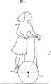
In another embodiment, at US Patent NO.5,701,965 and 5,971, under the situation of the personal transporter described in 091, conveying arrangement is statically stable with regard to plane inclination transversely only, these patents are incorporated herein by reference.For example, Fig. 3 shows a kind of main personal transporter of indicating with label 38.People's conveying arrangement 38 comprises support platform 32.Handle 34 links to each other with support platform 32.Human body 30 stand on the support platform 32, can operate the conveying arrangement 38 of present embodiment like this by the mode that is similar to scooter.The inclination of human body 30 impels support platform 32 to tilt, and this passes through, and is not limited to, and the inclination sensor (not shown) detects.Thereby providing a kind of control loop human body 30 to cause wheel 33 to produce around axle 35 in the inclination of going up forward or backwards changes distance, impels vehicle to quicken thus.Yet vehicle 38 is static instabilities, thereby needs this control loop of operation to keep dynamic stability.
In the above-described embodiment, controller receives the signal at expression center-of-gravity position and/or inclination angle from sensor assembly.Controller is controlled at least one in a plurality of wheels of motorized drive arrangement at least based on center-of-gravity position and/or inclination angle.This controller also can respond the order from other operation interface such as joystick or dial that for example links to each other with handle.
According to one embodiment of present invention, the block diagram of Fig. 4 shows the controller 40 of the motorized drive of control conveying arrangement.Controller 40 receives about the center-of-gravity position of indication loaded support platform and/or the input at inclination angle from sensor assembly 44.At least based on the input from sensor assembly 44, controller 40 is handled at least one motorized drive 45,46.This controller 40 also is connected with wheel rotation sensor 43 with user interface 41.User interface 41 for example can comprise opening or closing of steering controller 40.When controller 40 cut out, the wheel of conveying arrangement can move freely, thereby this conveying arrangement can be used as representative type driving scooter.User interface 41 is may command lockout mechanism 42 also, is used for locking one or more wheels of conveying arrangement.
For instance, but be not limited thereto, control algorithm can adopt following form:
Change apart from order=K (C+O)
Wherein K=gain
The C=definition has the vector of loaded support platform with respect to the center of gravity of bench mark on the conveying arrangement, and
The O=side-play amount
The center-of-gravity position of loaded support platform, C can be the form of error term, the desired position of center of gravity that this error term is defined as load platform deducts the center-of-gravity position that is detected of load platform.In control algorithm, the desired position of center of gravity of load platform can be predetermined constant.Select as another, the object on the conveying arrangement can pass through the setting of the desired position of center of gravity of user interface 41 control platform.For example, in trampling the flat-bed process and allowing before conveying arrangement moves, object can activate the switch on the conveying arrangement handle, thereby determines the ideal position of center of gravity based on the input that is received from sensor assembly 44.This allows object to obtain a known initial position, thereby object can depart from the change that this initial position causes the center-of-gravity position of load platform then.
Gain, K can be the constant of being scheduled to, perhaps can be by operating personal by user interface 41 input/adjustings.Gain K, vector the most normally, its transfer is apart from the scalar product that is confirmed as gaining with the centre-of-gravity displacement vector.Conveying arrangement can be controlled with K for the responsiveness of the mass centre changing of loaded support platform.For example, if the value of at least one element of vector K increases, chaufeur will be perceived significantly (stiffer) response, because the less variation of the center-of-gravity position of load platform will cause bigger commentaries on classics apart from control.
Except the direct effect of C, perhaps be independent of the direct effect of C, side-play amount O can be combined in the control algorithm with control and be applied to commentaries on classics distance on the motorized drive.Like this, for example, the user can provide input via the user interface 41 of any kind of, and this input can be by handling with the control system of the variation equivalence of for example load platform center-of-gravity position.
Like this, in the above-mentioned embodiment of the invention, can be by changing the center-of-gravity position of load platform, for example tilt or selectively change the motion that conveying arrangement is controlled in his position on platform by operating personal.According to control algorithm, center of gravity along forwards to initial change can at least one wheel, produce and just changeing distance, thereby impel wheel to move forward.Similarly, center of gravity can produce negative commentaries on classics distance along the initial change of backward directions at least one wheel, thereby impels wheel to move backward.So if object continues to tilt (or keeping its change location on platform), thereby the center of gravity of load platform remains unchanged, motor will continue with approximately uniform speed transmitting torque so.
As mentioned above, conveying arrangement is except being the steady stability on the longitudinal plane, and it also can be statically stable with regard to inclination on Transverse plane, represents that wherein the signal of center-of-gravity position is being determined on the vertical and horizontal or on one of them direction.In these embodiments, the center of gravity of load platform can laterally change by oneself, and perhaps the center of gravity on longitudinal plane changes, thus the motion of control conveying arrangement.For example, but be not limited to, vertical change may command of the center-of-gravity position of loaded support platform is moved longitudinally, and the steering of the horizontal change may command conveying arrangement of center of gravity.
In a embodiment, for example by provide independently motor can realize driving to left and right wheels with wheel of at least two horizontally sets (also promptly, left and right wheels).The required commentaries on classics distance of commentaries on classics distance that left motor is required and right motor can be calculated separately.In addition, the those of ordinary skill in control field all knows, can regulate the two tracking of revolver motion and right wheel motion, carries out undesirable rotation and allows the performance between two motors there are differences to prevent vehicle.
According to other embodiments of the invention, Fig. 5 shows a kind of conveying arrangement 501, it comprise can bearing load support platform 502.Support platform 502 is connected to a plurality of wheels 503 and 504, and is statically stable with regard to inclination on longitudinal plane and Transverse plane.In pivoting member 507 and the wheel 503 and 504 at least one is connected pivotally, and this pivoting member 507 can tilt like this.For example, a plurality of elements that contact to earth can comprise the wheel of two horizontally sets, right wheel 504 and revolver (not shown), they can be around axle 545 rotations, thus wherein pivoting member 507 is connected this pivoting member 507 pivotally with this axle 545 and can tilts at longitudinal plane.
The inclination of pivoting member 507 can realize that this operation interface can be, but be not limited to handle 512 by operation interface.Handle 512 is connected with pivoting member 507, thereby for example handle 512 inclination in a longitudinal direction will cause pivoting member 507 to tilt accordingly.
At least one sensor 555 produces a signal that shows pivoting member 507 run-off the straights.Sensor 555 can be, but be not limited to: spring and relevant sensor (for example rang sensor); Load transducer; Such as incline level or gyroscope, provide support platform 502 bevelled inclination sensors; Whisker (whiskers); Angular rate sensor; And/or the noncontacting proximity sensor such as super sonic or optics.Can measure the inclination angle with respect to the bench mark near the position S. A. on gravity, ground and/or the conveying arrangement.Controller comes the order motorized drive arrangement to drive at least one wheel 504 based on described inclination at least.
In each embodiment, pivoting member 507 is for example by a plurality of spring 508-509 and support platform 502 flexible-disc joints.When handle 512 was not subjected to handling, this allowed pivoting member 507 to keep predetermined inclination angle.In each embodiment, thereby controller can set in advance based on the predetermined specific motion of inclination angle control.For example, when detecting predetermined inclination angle, controller may command motorized drive arrangement does not produce motion.The responsiveness of conveying arrangement also can be controlled by spring 508-509.
As described in above-mentioned embodiment, the driving of conveying arrangement 501 can be passed through, and for example but be not restricted to, is arranged on the handle or controls near the user interface of the arbitrary number well known in the art such as joystick or thumb wheel of handle.As mentioned above, motorized drive arrangement can have independently motor, is used for based on revolver (not shown) that drives horizontally set from the signal that user interface received independently and right wheel 504.The revolver (not shown) of horizontally set and right wheel 504 can be for example, to support conveying arrangement 501 to rotate caster wheel thereby can rotate around vertical axis.
In the above embodiment of the present invention, conveying arrangement can comprise the indicating device of reference number 540 indications among Fig. 5.According to the motion that motorized drive arrangement is controlled, indicating device 540 can be from visual observation.For example, indicating device 540 can be benchmark with the speed-up command.Can include, but not limited to the lamp that can throw light on from the indicating device 540 of visual observation.
Described embodiment of the present invention only is used for illustration, and variations and modifications are obvious to those skilled in the art.All such changes and modifications are intended to drop in the subsidiary scope of the invention that claim limited.
Claims (31)
1. conveying arrangement comprises:
The support platform that is used for bearing load, loaded support platform are limited with longitudinal plane and Transverse plane and are characterized by with respect to ground-surface inclination and distribution of load, and this distribution of load is determined this inclination;
A plurality of elements that contact to earth, they are connected with support platform, thus this conveying arrangement is statically stable with regard to plane inclination along the longitudinal;
Motorized drive arrangement is used for driving at least one of a plurality of elements that contact to earth;
Sensor assembly is used for tilting to produce the signal of indicating the loaded support platform distribution of load based on this flat-bed;
Controller is used for based on distribution of load control motorized drive arrangement.
2. conveying arrangement according to claim 1 is characterized in that, described a plurality of elements that contact to earth comprise at least two wheels.
3. conveying arrangement according to claim 2 is characterized in that, described at least two wheels comprise:
Can be around first wheel of primary shaft rotation; With
Can be around second wheel of second rotation, this second is positioned at the primary shaft back.
4. conveying arrangement according to claim 1 is characterized in that controller is configured to control by the distribution of load that longitudinally changes loaded support platform the longitudinal movement of conveying arrangement.
5. conveying arrangement according to claim 1, it is characterized in that, loaded support platform characterizes by the center of gravity with certain position, and its middle controller is configured to control by the center-of-gravity position that longitudinally changes loaded support platform the longitudinal movement of conveying arrangement.
6. conveying arrangement according to claim 1 is characterized in that controller is configured to control by the distribution of load of horizontal change loaded support platform the rotation of conveying arrangement.
7. conveying arrangement according to claim 1 is characterized in that loaded support platform is characterized by the center of gravity with certain position, and its middle controller is configured to control by the center-of-gravity position of horizontal change loaded support platform the rotation of conveying arrangement.
8. conveying arrangement according to claim 1 is characterized in that, this conveying arrangement all is statically stable with regard to plane and Transverse plane tilt along the longitudinal thereby a plurality of element that contacts to earth is connected with support platform.
9. conveying arrangement according to claim 1, wherein this sensor assembly comprises inclination sensor.
10. conveying arrangement according to claim 1 is characterized in that, sensor assembly adds side-play amount when producing signal.
11. conveying arrangement according to claim 10 is characterized in that, described side-play amount can be regulated by user interface.
12. conveying arrangement according to claim 1 is characterized in that, thereby controller control motorized drive arrangement makes conveying arrangement quicken, this conveying arrangement also comprises the indicating device that indication is provided based on described acceleration/accel, and described indication can be from visual observation.
13. conveying arrangement according to claim 1 is characterized in that, can see indicating device in the conveying arrangement back.
14. conveying arrangement according to claim 1 is characterized in that, conveying arrangement also comprises user interface, and its middle controller is controlled motorized drive arrangement based on the signal that is provided by user interface at least.
15. conveying arrangement according to claim 14 is characterized in that, user interface is selected from the user interface group that is made of joystick and calibrated disc.
16. method of controlling conveying arrangement, this conveying arrangement has the support platform of bearing load, loaded support platform is limited with longitudinal plane and Transverse plane and is characterized by distribution of load, this conveying arrangement comprises that also thereby a plurality of these conveying arrangements of element that contact to earth are statically stable with regard to plane inclination along the longitudinal, this conveying arrangement also comprises at least one the motorized drive arrangement that is used for driving a plurality of elements that contact to earth, and described method comprises:
Determine loaded support platform with respect to ground-surface inclination, distribution of load is determined this inclination;
At least based on the indication distribution of load this tilt to control motorized drive arrangement.
17. method according to claim 16 is characterized in that, determines that the step of the gravity loading distribution of load platform comprises the inclination angle of detecting loaded support platform.
18. method according to claim 16 is characterized in that, determines that the step of the distribution of load of load platform comprises the roll angle that detects loaded support platform.
19. method according to claim 16 is characterized in that, the step of control motorized drive is also based on the control signal from the conveying arrangement user interface.
20. method according to claim 16 comprises that also provide based on the motion of being controlled can be from the step of the indication of visual observation.
21. method according to claim 20 is characterized in that, providing based on the acceleration/accel of being controlled can be from the indication of visual observation.
22. method according to claim 21 is characterized in that, provides can comprise from the step of the indication of visual observation illuminating lamp is provided.
23. a conveying arrangement comprises:
The support platform that is used for bearing load, support platform are limited with longitudinal plane and Transverse plane;
A plurality of elements that contact to earth, this support platform is statically stable with regard to plane and Transverse plane tilt along the longitudinal thereby they are connected with support platform;
Pivoting member, thus it with a plurality of elements that contact to earth at least one be connected this pivoting member pivotally and can tilt;
Make pivoting member bevelled user interface;
Sensor assembly is used to produce the signal that shows the pivoting member run-off the straight;
Motorized drive arrangement is used for driving at least one of a plurality of elements that contact to earth; With
Controller, it controls motorized drive arrangement based on the inclination that pivoting member takes place.
24. conveying arrangement according to claim 23 is characterized in that, pivoting member at least longitudinally plane can tilt.
25. conveying arrangement according to claim 23 is characterized in that, a plurality of elements that contact to earth comprise the wheel that pivots of two horizontally sets, and pivoting member is connected pivotally with this axle.
26. conveying arrangement according to claim 23 is characterized in that, pivoting member and support platform flexible-disc joint.
27. conveying arrangement according to claim 26 is characterized in that, pivoting member is via at least one spring and support platform flexible-disc joint.
28. conveying arrangement according to claim 23 is characterized in that, user interface is and pivoting member bonded assembly handle.
29. method of controlling conveying arrangement, this conveying arrangement has the support platform of bearing load, this support platform is limited with longitudinal plane and Transverse plane, conveying arrangement comprises that thereby a plurality of these conveying arrangements of element that contact to earth are statically stable with regard to inclination, thereby conveying arrangement also comprise with the S. A. of at least one element that contacts to earth pivotally this pivoting member of bonded assembly pivoting member can tilt, and at least one the motorized drive arrangement that is used for driving a plurality of elements that contact to earth, described method comprises:
Make pivoting member tilt; With
At least control motorized drive arrangement based on described inclination.
30. method according to claim 29 is characterized in that, causes that described bevelled step comprises feasible and the run-off the straight of pivoting member bonded assembly handle.
31. method according to claim 29 also comprises the step with pivoting member and support platform flexible-disc joint.
Applications Claiming Priority (2)
| Application Number | Priority Date | Filing Date | Title |
|---|---|---|---|
| US39529902P | 2002-07-12 | 2002-07-12 | |
| US60/395,299 | 2002-07-12 |
Publications (2)
| Publication Number | Publication Date |
|---|---|
| CN1681678A CN1681678A (en) | 2005-10-12 |
| CN100333937C true CN100333937C (en) | 2007-08-29 |
Family
ID=30115853
Family Applications (1)
| Application Number | Title | Priority Date | Filing Date |
|---|---|---|---|
| CNB03821668XA Expired - Fee Related CN100333937C (en) | 2002-07-12 | 2003-07-11 | Motion control of a transporter |
Country Status (7)
| Country | Link |
|---|---|
| US (4) | US20040055796A1 (en) |
| EP (1) | EP1539522A2 (en) |
| JP (2) | JP5099971B2 (en) |
| CN (1) | CN100333937C (en) |
| AU (1) | AU2003247975A1 (en) |
| CA (1) | CA2492393A1 (en) |
| WO (1) | WO2004007233A2 (en) |
Families Citing this family (92)
| Publication number | Priority date | Publication date | Assignee | Title |
|---|---|---|---|---|
| US7090040B2 (en) | 1993-02-24 | 2006-08-15 | Deka Products Limited Partnership | Motion control of a transporter |
| US7275607B2 (en) | 1999-06-04 | 2007-10-02 | Deka Products Limited Partnership | Control of a personal transporter based on user position |
| US7210544B2 (en) | 2002-07-12 | 2007-05-01 | Deka Products Limited Partnership | Control of a transporter based on attitude |
| GB2427832A (en) * | 2004-05-04 | 2007-01-10 | Yonatan Manor | Device and method for regaining balance |
| US7458435B2 (en) * | 2004-08-05 | 2008-12-02 | Yamaha Hatsudoki Kabushiki Kaisha | Vehicle control unit and vehicle |
| JP2006076699A (en) * | 2004-09-08 | 2006-03-23 | Daifuku Co Ltd | Article carrying vehicle |
| WO2007013282A1 (en) * | 2005-07-26 | 2007-02-01 | Matsushita Electric Industrial Co., Ltd. | Inverted two-wheel running type robot and method of controlling the same |
| US8099200B2 (en) * | 2005-09-30 | 2012-01-17 | Coombs Joshua D | Vehicle interface based on the weight distribution of a user |
| US20090076686A1 (en) * | 2005-09-30 | 2009-03-19 | Jeffrey Schox | Vehicle interface to communicate a safety alert mode command |
| US20070074922A1 (en) * | 2005-09-30 | 2007-04-05 | Coombs Joshua D | Vehicle interface based on a shift of the torso of a user |
| US7744331B2 (en) * | 2006-01-26 | 2010-06-29 | Xerox Corporation | Transport vehicle and method |
| FI119717B (en) * | 2006-05-04 | 2009-02-27 | Polar Electro Oy | User-specific performance meter, method, and computer software product |
| US7847504B2 (en) * | 2006-10-10 | 2010-12-07 | Carnegie Mellon University | Dynamic balancing mobile robot |
| US7798510B2 (en) * | 2007-02-15 | 2010-09-21 | Scott Patrick Comstock | Multi-wheeled vehicle |
| JP4506776B2 (en) * | 2007-04-05 | 2010-07-21 | トヨタ自動車株式会社 | Traveling device |
| JP5110267B2 (en) * | 2007-06-26 | 2012-12-26 | 株式会社エクォス・リサーチ | Traveling vehicle |
| US8954476B2 (en) * | 2007-08-06 | 2015-02-10 | Nipendo Ltd. | System and method for mediating transactions of digital documents |
| KR101330172B1 (en) * | 2008-07-29 | 2013-11-15 | 도요타 지도샤(주) | Coaxil two-wheel vehicle and method for controlling same |
| US8170780B2 (en) | 2008-11-06 | 2012-05-01 | Segway, Inc. | Apparatus and method for control of a vehicle |
| US8141669B1 (en) | 2009-02-12 | 2012-03-27 | Laymaster Larry A | Motorized personal transporter |
| ES2547959T3 (en) | 2010-02-26 | 2015-10-09 | Segway Inc. | Apparatus and methods for vehicle control |
| US20130119639A1 (en) * | 2011-11-16 | 2013-05-16 | Zafer J.S. Al Osaimi | Multifunction utility cart |
| US8403095B1 (en) * | 2011-12-05 | 2013-03-26 | Bryce A. Ecklein | Step on-step off motorized utility vehicle |
| JP5929708B2 (en) * | 2012-10-26 | 2016-06-08 | トヨタ自動車株式会社 | Inverted moving body |
| WO2014115265A1 (en) * | 2013-01-23 | 2014-07-31 | Sato Kuniaki | Mobile device for single rider |
| US9616318B2 (en) * | 2013-03-15 | 2017-04-11 | Stealth Electric Longboards | Powered personal transportation systems and methods |
| DE202014010649U1 (en) | 2013-05-06 | 2016-02-26 | Future Motion, Inc. | Self-stabilizing skateboard |
| WO2015009369A1 (en) * | 2013-07-17 | 2015-01-22 | C. Johnson Industries, Llc | Multi-wheel single operator transport platform |
| JP5979322B2 (en) * | 2013-12-25 | 2016-08-24 | 株式会社村田製作所 | Wheelbarrow |
| CN103950479B (en) * | 2014-02-20 | 2017-11-10 | 青岛海艺自动化技术有限公司 | With the snake-shaped robot for adapting to out-of-flatness ground ability |
| US9808705B2 (en) * | 2014-06-10 | 2017-11-07 | Acton, Inc. | Wearable personal transportation system |
| WO2016073786A1 (en) | 2014-11-05 | 2016-05-12 | Future Motion, Inc. | Rider detection system |
| DE202015004507U1 (en) * | 2015-06-25 | 2016-09-29 | Isel Facility GmbH | Vehicle for transporting loads or passengers |
| US10252724B2 (en) | 2015-09-24 | 2019-04-09 | P&N Phc, Llc | Portable two-wheeled self-balancing personal transport vehicle |
| DE102015218950B4 (en) * | 2015-09-30 | 2019-01-31 | Siemens Healthcare Gmbh | Wheel suspension of an electric drive |
| CN106564546B (en) | 2015-10-10 | 2020-08-14 | 杭州骑客智能科技有限公司 | Full-posture electrodynamic balance swing car |
| US11260905B2 (en) | 2015-10-10 | 2022-03-01 | Hangzhou Chic Intelligent Technology Co., Ltd. | Human-machine interaction vehicle |
| WO2017077362A1 (en) | 2015-11-03 | 2017-05-11 | Koofy Development Limited | Self balancing single wheel board with shock absorber |
| CN105416353A (en) * | 2015-11-26 | 2016-03-23 | 成都佳美嘉科技有限公司 | Novel logistic trolley |
| USD797875S1 (en) | 2016-01-19 | 2017-09-19 | Koofy Development Limited | Skateboard |
| CN109562291A (en) | 2016-01-31 | 2019-04-02 | 酷飞创新有限公司 | The power car based on foot pedal with visual control |
| WO2017147347A1 (en) | 2016-02-23 | 2017-08-31 | Deka Products Limited Partnership | Mobility device control system |
| US10908045B2 (en) | 2016-02-23 | 2021-02-02 | Deka Products Limited Partnership | Mobility device |
| US11399995B2 (en) | 2016-02-23 | 2022-08-02 | Deka Products Limited Partnership | Mobility device |
| US10926756B2 (en) | 2016-02-23 | 2021-02-23 | Deka Products Limited Partnership | Mobility device |
| US9598141B1 (en) | 2016-03-07 | 2017-03-21 | Future Motion, Inc. | Thermally enhanced hub motor |
| US10112680B2 (en) | 2016-03-07 | 2018-10-30 | Future Motion, Inc. | Thermally enhanced hub motor |
| USD827747S1 (en) | 2016-03-14 | 2018-09-04 | Koofy Innovation Limited | Skateboard |
| GB2563803B (en) * | 2016-03-23 | 2021-08-04 | Ford Global Tech Llc | Versatile urban electric transport device and system |
| CA3024145A1 (en) | 2016-04-14 | 2017-10-19 | Deka Products Limited Partnership | User control device for a transporter |
| US10029738B2 (en) * | 2016-05-25 | 2018-07-24 | Exmark Manufacturing Company, Incorporated | Turf maintenance vehicle and support platform isolator system for same |
| CN211273514U (en) | 2016-06-02 | 2020-08-18 | 未来动力公司 | Electric vehicle |
| USD941948S1 (en) | 2016-07-20 | 2022-01-25 | Razor Usa Llc | Two wheeled board |
| USD803963S1 (en) | 2016-07-20 | 2017-11-28 | Razor Usa Llc | Two wheeled board |
| USD837323S1 (en) | 2018-01-03 | 2019-01-01 | Razor Usa Llc | Two wheeled board |
| USD840872S1 (en) | 2016-07-20 | 2019-02-19 | Razor Usa Llc | Two wheeled board |
| USD807457S1 (en) | 2016-07-20 | 2018-01-09 | Razor Usa Llc | Two wheeled board |
| US10772774B2 (en) | 2016-08-10 | 2020-09-15 | Max Mobility, Llc | Self-balancing wheelchair |
| TWI644824B (en) | 2016-10-11 | 2018-12-21 | 美商未來運行公司 | Suspension system for one-wheeled vehicle |
| US9999827B2 (en) | 2016-10-25 | 2018-06-19 | Future Motion, Inc. | Self-balancing skateboard with strain-based controls and suspensions |
| CN106426201B (en) * | 2016-10-31 | 2019-03-08 | 沈阳工业大学 | A kind of sitting posture service robot and direction of motion recognition methods |
| CN106741406B (en) * | 2016-12-29 | 2022-10-04 | 浙江骑客机器人科技有限公司 | Somatosensory longitudinal two-wheel vehicle |
| USD821517S1 (en) | 2017-01-03 | 2018-06-26 | Future Motion, Inc. | Skateboard |
| USD829612S1 (en) | 2017-05-20 | 2018-10-02 | Deka Products Limited Partnership | Set of toggles |
| USD846452S1 (en) | 2017-05-20 | 2019-04-23 | Deka Products Limited Partnership | Display housing |
| WO2019006652A1 (en) * | 2017-07-01 | 2019-01-10 | 杭州畅动智能科技有限公司 | Human-machine interaction motion sensing vehicle |
| TW201908194A (en) | 2017-07-25 | 2019-03-01 | 大陸商立盟智能科技(東莞)有限公司 | Electric vehicle and electric vehicle power opening and closing method |
| US11524740B2 (en) | 2017-08-05 | 2022-12-13 | Shane Chen | Transportation device having multiple axes of rotation and auto-balance based drive control |
| KR102002902B1 (en) * | 2017-10-13 | 2019-07-24 | 네이버랩스 주식회사 | Personal mobility |
| WO2019109102A1 (en) | 2017-12-01 | 2019-06-06 | Future Motion, Inc. | Control system for electric vehicles |
| US10010784B1 (en) | 2017-12-05 | 2018-07-03 | Future Motion, Inc. | Suspension systems for one-wheeled vehicles |
| DE212018000376U1 (en) | 2017-12-07 | 2020-07-10 | Future Motion, Inc. | Descent controls for unicycle vehicles |
| CN108000478B (en) * | 2017-12-13 | 2023-08-08 | 北京极智嘉科技股份有限公司 | Flexible base and transfer robot |
| WO2019126771A1 (en) | 2017-12-22 | 2019-06-27 | Razor Usa Llc | Electric balance vehicles |
| USD850552S1 (en) | 2018-02-23 | 2019-06-04 | Future Motion, Inc. | Skateboard |
| USD843532S1 (en) | 2018-02-23 | 2019-03-19 | Future Motion, Inc. | Skateboard |
| CA3106189A1 (en) | 2018-06-07 | 2019-12-12 | Deka Products Limited Partnership | System and method for distributed utility service execution |
| WO2020146420A1 (en) | 2019-01-07 | 2020-07-16 | Future Motion, Inc. | Self-balancing systems for electric vehicles |
| US10456658B1 (en) | 2019-02-11 | 2019-10-29 | Future Motion, Inc. | Self-stabilizing skateboard |
| USD889577S1 (en) | 2019-03-11 | 2020-07-07 | Future Motion, Inc. | Rotatable handle for electric vehicle |
| USD888175S1 (en) | 2019-03-11 | 2020-06-23 | Future Motion, Inc. | Electric vehicle front |
| USD881307S1 (en) | 2019-03-11 | 2020-04-14 | Future Motion, Inc. | Fender for electric vehicle |
| USD886929S1 (en) | 2019-03-11 | 2020-06-09 | Future Motion, Inc. | Rear bumper for electric vehicle |
| USD890278S1 (en) | 2019-03-11 | 2020-07-14 | Future Motion, Inc. | Electric vehicle |
| USD881308S1 (en) | 2019-03-11 | 2020-04-14 | Future Motion, Inc. | Fender for electric vehicle |
| USD890280S1 (en) | 2019-03-11 | 2020-07-14 | Future Motion, Inc. | Rider detection sensor for electric vehicle |
| USD897469S1 (en) | 2019-03-11 | 2020-09-29 | Future Motion, Inc. | Foot pad for electric vehicle |
| USD890279S1 (en) | 2019-03-11 | 2020-07-14 | Future Motion, Inc. | Electric vehicle with fender |
| US11343963B2 (en) * | 2019-05-09 | 2022-05-31 | Kubota Corporation | Stand-on lawnmower |
| US11273364B1 (en) | 2021-06-30 | 2022-03-15 | Future Motion, Inc. | Self-stabilizing skateboard |
| US11299059B1 (en) | 2021-10-20 | 2022-04-12 | Future Motion, Inc. | Self-stabilizing skateboard |
| US11890528B1 (en) | 2022-11-17 | 2024-02-06 | Future Motion, Inc. | Concave side rails for one-wheeled vehicles |
Citations (8)
| Publication number | Priority date | Publication date | Assignee | Title |
|---|---|---|---|---|
| US4151892A (en) * | 1976-04-28 | 1979-05-01 | Frank Francken | Motorized terrestrial surf-board |
| US5135063A (en) * | 1990-08-30 | 1992-08-04 | Smucker Manufacturing, Inc. | Power unit for driving manually-operated wheelchair |
| CN1028736C (en) * | 1990-11-01 | 1995-06-07 | 吉林工业大学 | Electronic controlling mechanical type automatic speed changing device and apparatus thereof |
| US5657828A (en) * | 1994-07-29 | 1997-08-19 | Shinko Denki Kabushiki Kaisha | Motor-driven cart |
| US6050357A (en) * | 1995-05-31 | 2000-04-18 | Empower Corporation | Powered skateboard |
| WO2000073101A1 (en) * | 1999-05-28 | 2000-12-07 | Deka Products Limited Partnership | System and method for control scheduling |
| US6223114B1 (en) * | 1998-03-20 | 2001-04-24 | Daimlerchrysler Ag | Process for controlling driving dynamics of a street vehicle |
| GB2358163A (en) * | 2000-01-12 | 2001-07-18 | Rover Group | A motor vehicle with controllable drive torque distribution between each of its driven wheels responding to vehicle load |
Family Cites Families (125)
| Publication number | Priority date | Publication date | Assignee | Title |
|---|---|---|---|---|
| US584127A (en) * | 1897-06-08 | Edmond draullette and ernest catois | ||
| US849270A (en) * | 1906-05-15 | 1907-04-02 | Andrew Schafer | Truck. |
| US1739716A (en) | 1927-10-27 | 1929-12-17 | Joseph B Fisher | Vehicle trailer |
| US2742973A (en) * | 1952-02-01 | 1956-04-24 | Johannesen Hans Arne Ingolf | Powered invalid chair and handle control therefor |
| US3145797A (en) * | 1960-09-21 | 1964-08-25 | Charles F Taylor | Vehicle |
| US3283398A (en) * | 1962-04-26 | 1966-11-08 | Artos Engineering Co | Art of producing electrical conductors from cord wire |
| US3260324A (en) * | 1963-11-12 | 1966-07-12 | Caesar R Suarez | Motorized unicycle |
| US3374845A (en) * | 1966-05-05 | 1968-03-26 | Selwyn Donald | Command control system for vehicles |
| US3399742A (en) * | 1966-06-23 | 1968-09-03 | Franklin S. Malick | Powered unicycle |
| US3446304A (en) * | 1966-08-08 | 1969-05-27 | Constantin Alimanestiand | Portable conveyor |
| US3450219A (en) * | 1967-03-13 | 1969-06-17 | John F Fleming | Stair-climbing vehicle |
| US3515401A (en) * | 1968-11-06 | 1970-06-02 | Eshcol S Gross | Stair climbing dolly |
| US3580344A (en) * | 1968-12-24 | 1971-05-25 | Johnnie E Floyd | Stair-negotiating wheel chair or an irregular-terrain-negotiating vehicle |
| US3596298A (en) * | 1969-05-14 | 1971-08-03 | John A Durst Jr | Lifting device |
| US3724874A (en) * | 1971-07-30 | 1973-04-03 | G Simpson | Vehicle drawbar assembly |
| US3860264A (en) * | 1973-01-15 | 1975-01-14 | Mattel Inc | Lean velocipede |
| SE381564B (en) * | 1973-03-19 | 1975-12-15 | Stiftelsen Teknisk Hjelp At Ha | ELECTRICLY WHEELCHAIR |
| US3872945A (en) * | 1974-02-11 | 1975-03-25 | Falcon Research And Dev Co | Motorized walker |
| US3967862A (en) * | 1975-03-17 | 1976-07-06 | Rockwell International Corporation | Anti-skid control system employing integral-plus-proportional control of pulsed modulation |
| US4018440A (en) * | 1975-03-31 | 1977-04-19 | Deutsch Fritz A | Invalid walker with wheel control mechanism |
| US4076270A (en) * | 1976-01-19 | 1978-02-28 | General Motors Corporation | Foldable cambering vehicle |
| US4088199A (en) * | 1976-02-23 | 1978-05-09 | Wolfgang Trautwein | Stabilized three-wheeled vehicle |
| US4062558A (en) | 1976-07-19 | 1977-12-13 | David Wasserman | Unicycle |
| US4094372A (en) * | 1977-02-28 | 1978-06-13 | Notter Michael A | Motorized skateboard with uni-directional rear mounting |
| US4111445A (en) * | 1977-06-09 | 1978-09-05 | Kenneth Haibeck | Device for supporting a paraplegic in an upright position |
| US4109741A (en) * | 1977-07-29 | 1978-08-29 | Gabriel Charles L | Motorized unicycle wheel |
| DE2807517C3 (en) * | 1978-02-22 | 1980-12-04 | Habegger, Willy, Huenibach Bei Thun (Schweiz) | Driving and walking gear for vehicles, especially mobile cranes, excavators and the like |
| US4222449A (en) * | 1978-06-08 | 1980-09-16 | Feliz Jack M | Step-climbing wheel chair |
| US4293052A (en) * | 1978-07-17 | 1981-10-06 | Daswick Alexander C | Lightweight two-wheeled vehicle |
| US4264082A (en) * | 1979-03-26 | 1981-04-28 | Fouchey Jr Charles J | Stair climbing cart |
| DE2915387A1 (en) * | 1979-04-14 | 1980-10-16 | Heinz Eichholz | ELECTRIC VEHICLE |
| US4325565A (en) * | 1980-03-03 | 1982-04-20 | General Motors Corporation | Cambering vehicle |
| US4373600A (en) * | 1980-07-18 | 1983-02-15 | Veda, Inc. | Three wheel drive vehicle |
| US4363493A (en) | 1980-08-29 | 1982-12-14 | Veneklasen Paul S | Uni-wheel skate |
| US4740001A (en) * | 1981-09-14 | 1988-04-26 | Torleumke Keith R | Sprag wheel |
| US4375840A (en) * | 1981-09-23 | 1983-03-08 | Campbell Jack L | Mobile support |
| US4566707A (en) * | 1981-11-05 | 1986-01-28 | Nitzberg Leonard R | Wheel chair |
| US4570078A (en) * | 1982-05-27 | 1986-02-11 | Honda Giken Kogyo Kabushiki Kaisha | Switch assembly for a motor vehicle |
| US4571844A (en) * | 1982-06-09 | 1986-02-25 | Jeco Co., Ltd. | Angle change detector |
| JPS6025302U (en) | 1983-07-22 | 1985-02-21 | アツプリカ葛西株式会社 | electric children's rides |
| US4510956A (en) * | 1983-08-15 | 1985-04-16 | Lorraine King | Walking aid, particularly for handicapped persons |
| US4645230A (en) * | 1983-12-13 | 1987-02-24 | Hammons Robert E | Collapsible trailer |
| US4919255A (en) * | 1984-06-22 | 1990-04-24 | Figgie International Inc. | Zero pressure accumulating conveyor and module |
| FR2576863A1 (en) | 1985-01-31 | 1986-08-08 | Brunet Pierre | MOTORIZED DISPLACEMENT DEVICE, FOR EXAMPLE FOR RUNNING AND DESCENDING STAIRS |
| GB8515992D0 (en) * | 1985-06-25 | 1985-07-31 | Hester R | Wheelchair |
| US4657272A (en) * | 1985-09-11 | 1987-04-14 | Davenport James M | Wheeled vehicle |
| US4624469A (en) * | 1985-12-19 | 1986-11-25 | Bourne Jr Maurice W | Three-wheeled vehicle with controlled wheel and body lean |
| DE3752081T2 (en) * | 1986-01-28 | 1998-01-08 | Michael Reid | Orthopedic carriage |
| US4716980A (en) * | 1986-02-14 | 1988-01-05 | The Prime Mover Company | Control system for rider vehicles |
| US4786069A (en) * | 1986-06-30 | 1988-11-22 | Tang Chun Yi | Unicycle |
| US4770410A (en) * | 1986-07-03 | 1988-09-13 | Brown Guies L | Walker |
| GB8618044D0 (en) | 1986-07-24 | 1986-09-03 | Sheeter E | Vehicle |
| WO1988000899A1 (en) * | 1986-07-28 | 1988-02-11 | Arthur George Yarrington | Heli-hover amphibious surface effect vehicle |
| US4802542A (en) * | 1986-08-25 | 1989-02-07 | Falcon Rehabilitation Products, Inc. | Powered walker |
| US4809804A (en) * | 1986-08-25 | 1989-03-07 | Falcon Rehabilitation Products, Inc. | Combination wheelchair and walker apparatus |
| US4685693A (en) * | 1986-09-16 | 1987-08-11 | Vadjunec Carl F | Upright wheelchair |
| JPH0322036Y2 (en) * | 1986-11-12 | 1991-05-14 | ||
| JPS63150176A (en) * | 1986-12-15 | 1988-06-22 | 工業技術院長 | Walking control method of dynamic walking robot |
| US4869279A (en) * | 1986-12-22 | 1989-09-26 | Hedges Harry S | Walker |
| US4746132A (en) * | 1987-02-06 | 1988-05-24 | Eagan Robert W | Multi-wheeled cycle |
| CA1275296C (en) | 1987-05-04 | 1990-10-16 | Pierre Decelles | Climbing and descending vehicle |
| US4798255A (en) * | 1987-10-29 | 1989-01-17 | Wu Donald P H | Four-wheeled T-handlebar invalid carriage |
| US4874055A (en) * | 1987-12-16 | 1989-10-17 | Beer Robin F C | Chariot type golf cart |
| JPH0436992Y2 (en) * | 1988-02-16 | 1992-09-01 | ||
| US4890853A (en) * | 1988-03-07 | 1990-01-02 | Luanne Olson | Wheelchair walker |
| US4919225A (en) * | 1988-03-31 | 1990-04-24 | Sturges Daniel D | Platform oriented transportation vehicle |
| US4863182A (en) * | 1988-07-21 | 1989-09-05 | Chern Jiuun F | Skate bike |
| US4953851A (en) * | 1988-11-07 | 1990-09-04 | Sherlock Lila A | Safety mobilizer walker |
| US4875055A (en) * | 1988-11-21 | 1989-10-17 | Eastman Kodak Company | Simplified multicolor fluid system for continuous ink jet printer |
| US4998596A (en) * | 1989-05-03 | 1991-03-12 | Ufi, Inc. | Self-propelled balancing three-wheeled vehicle |
| CH681353A5 (en) * | 1989-05-17 | 1993-03-15 | Aluweld Sa | |
| EP0398081B1 (en) * | 1989-05-17 | 1995-04-12 | Aluweld S.A. | Transmission device |
| US5248007A (en) * | 1989-11-21 | 1993-09-28 | Quest Technologies, Inc. | Electronic control system for stair climbing vehicle |
| US5011170A (en) * | 1990-03-26 | 1991-04-30 | Forbes Alexander D | Pedal cycle and motorcycle trailer |
| US5002295A (en) * | 1990-04-19 | 1991-03-26 | Pro-China Sporting Goods Industries Inc. | Unicycle having an eccentric wheel |
| US5011171A (en) * | 1990-04-20 | 1991-04-30 | Cook Walter R | Self-propelled vehicle |
| US4985947A (en) * | 1990-05-14 | 1991-01-22 | Ethridge Kenneth L | Patient assist device |
| DE4016610A1 (en) | 1990-05-23 | 1991-11-28 | Audi Ag | SAFETY DEVICE ON A MOTOR VEHICLE WITH AN INFLATABLE GAS PILLOW |
| US5171173A (en) | 1990-07-24 | 1992-12-15 | Zebco Corporation | Trolling motor steering and speed control |
| DE4030119A1 (en) * | 1990-09-24 | 1992-03-26 | Uwe Kochanneck | MULTIBLOCK ROBOT |
| DE4134831C2 (en) * | 1991-10-22 | 1995-05-18 | Mannesmann Ag | Arrangement for determining a coefficient of friction information |
| JP3070015B2 (en) * | 1990-11-30 | 2000-07-24 | 本田技研工業株式会社 | Travel control system for unstable vehicles |
| US5221883A (en) * | 1990-11-30 | 1993-06-22 | Honda Giken Kogyo Kabushiki Kaisha | System for controlling locomotion of legged walking robot |
| US5064209A (en) | 1990-12-03 | 1991-11-12 | Kurschat Erich G | Combined trailer/wheelchair |
| US5390753A (en) * | 1991-01-15 | 1995-02-21 | Parker; Bruce H. | Personal walker with powered wheels |
| JP3280392B2 (en) | 1991-04-01 | 2002-05-13 | アイシン・エィ・ダブリュ株式会社 | Driving force control device for electric vehicle |
| US5168947A (en) | 1991-04-09 | 1992-12-08 | Rodenborn Eugene P | Motorized walker |
| US5158493A (en) * | 1991-05-30 | 1992-10-27 | Richard Morgrey | Remote controlled, multi-legged, walking robot |
| US5186270A (en) * | 1991-10-24 | 1993-02-16 | Massachusetts Institute Of Technology | Omnidirectional vehicle |
| US5314034A (en) * | 1991-11-14 | 1994-05-24 | Chittal Nandan R | Powered monocycle |
| US5240266A (en) * | 1992-04-20 | 1993-08-31 | Kelley Reginald W | Hitch for one-wheeled trailer to be towed by two-wheeled vehicles |
| US5354569A (en) * | 1992-07-16 | 1994-10-11 | Brown Richard S | Method of packaging lettuce for storing and shipping |
| US5366036A (en) | 1993-01-21 | 1994-11-22 | Perry Dale E | Power stand-up and reclining wheelchair |
| US5701965A (en) * | 1993-02-24 | 1997-12-30 | Deka Products Limited Partnership | Human transporter |
| US5971091A (en) | 1993-02-24 | 1999-10-26 | Deka Products Limited Partnership | Transportation vehicles and methods |
| US5350033A (en) * | 1993-04-26 | 1994-09-27 | Kraft Brett W | Robotic inspection vehicle |
| JPH0787602A (en) * | 1993-09-17 | 1995-03-31 | Matsushita Electric Ind Co Ltd | Protective unit for electric automobile |
| US5655615A (en) * | 1994-01-06 | 1997-08-12 | Mick; Jeffrey | Wheeled vehicle for distributing agricultural materials in fields having uneven terrain |
| EP1298041B1 (en) * | 1995-02-03 | 2011-10-05 | Deka Products Limited Partnership | Motorized balanced single person transportation vehicles |
| JP2692635B2 (en) * | 1995-03-17 | 1997-12-17 | 日本電気株式会社 | Nonvolatile semiconductor memory device and data erasing method thereof |
| US5701968A (en) | 1995-04-03 | 1997-12-30 | Licile Salter Packard Children's Hospital At Stanford | Transitional power mobility aid for physically challenged children |
| US5641173A (en) * | 1995-04-20 | 1997-06-24 | Cobb, Jr.; William T. | Cycling trailer |
| US6059062A (en) * | 1995-05-31 | 2000-05-09 | Empower Corporation | Powered roller skates |
| US5775452A (en) * | 1996-01-31 | 1998-07-07 | Patmont Motor Werks | Electric scooter |
| US5718534A (en) * | 1996-03-13 | 1998-02-17 | Fine Line Plastics Corp. | Rear drive ride-on tractor unit for propelling steerable utility vehicles such as walk-behind paint stripers |
| JPH09272413A (en) * | 1996-04-03 | 1997-10-21 | Osamu Tsujimoto | Vehicle accident prevention automatic braking device and driving condition displaying device |
| DE19625498C1 (en) * | 1996-06-26 | 1997-11-20 | Daimler Benz Ag | Steering device for controlling longitudinal and cross movement of road vehicle |
| US5872582A (en) * | 1996-07-02 | 1999-02-16 | Hewlett-Packard Company | Microfluid valve for modulating fluid flow within an ink-jet printer |
| JPH1023613A (en) * | 1996-07-04 | 1998-01-23 | Yamaha Motor Co Ltd | Motor-driven moving device |
| JP3451848B2 (en) * | 1996-09-10 | 2003-09-29 | トヨタ自動車株式会社 | Drive control device for electric vehicle |
| US5873582A (en) * | 1997-02-21 | 1999-02-23 | Kauffman, Jr.; Donald J. | Convertible hunting utility cart |
| US6225977B1 (en) * | 1997-03-25 | 2001-05-01 | John Li | Human balance driven joystick |
| US5947505A (en) * | 1997-08-22 | 1999-09-07 | Martin; John W. | Lawn mower riding sulky |
| US5921844A (en) * | 1997-10-15 | 1999-07-13 | Hollick; Michael F. | Toy caddy |
| JPH11197191A (en) * | 1998-01-08 | 1999-07-27 | Hiroto Uenaka | Motor-driven wheelchair |
| US6125957A (en) * | 1998-02-10 | 2000-10-03 | Kauffmann; Ricardo M. | Prosthetic apparatus for supporting a user in sitting or standing positions |
| JP3552542B2 (en) * | 1998-07-28 | 2004-08-11 | 松下電工株式会社 | Electric wheelchair |
| JP2000108892A (en) * | 1998-10-07 | 2000-04-18 | Hitachi Zosen Corp | Carrier device |
| DE69922239T2 (en) * | 1998-10-21 | 2005-12-15 | Deka Products Ltd. Partnership | DEFECTIVE FURTHER FUNCTIONING CONTROL STRUCTURE FOR A WHEELCHAIR |
| US6302230B1 (en) * | 1999-06-04 | 2001-10-16 | Deka Products Limited Partnership | Personal mobility vehicles and methods |
| US6969079B2 (en) * | 2002-06-05 | 2005-11-29 | Deka Products Limited Partnership | Multiple-passenger transporter |
| US6435535B1 (en) * | 2000-03-01 | 2002-08-20 | Deka Products Limited Partnership | Trailer for balancing vehicle |
| US6288505B1 (en) * | 2000-10-13 | 2001-09-11 | Deka Products Limited Partnership | Motor amplifier and control for a personal transporter |
| DE10209093A1 (en) * | 2002-03-01 | 2003-09-18 | Ms Handelsvertretung Consultin | Powered scooter for standing user has pair of front wheels driven by motor and tread board with single rear wheel |
| JP2003291819A (en) * | 2002-03-29 | 2003-10-15 | Sanyo Electric Co Ltd | Carrier |
-
2003
- 2003-07-11 WO PCT/US2003/021662 patent/WO2004007233A2/en active Application Filing
- 2003-07-11 CA CA002492393A patent/CA2492393A1/en not_active Abandoned
- 2003-07-11 CN CNB03821668XA patent/CN100333937C/en not_active Expired - Fee Related
- 2003-07-11 US US10/618,082 patent/US20040055796A1/en not_active Abandoned
- 2003-07-11 AU AU2003247975A patent/AU2003247975A1/en not_active Abandoned
- 2003-07-11 EP EP03764477A patent/EP1539522A2/en not_active Withdrawn
- 2003-07-11 JP JP2004521654A patent/JP5099971B2/en not_active Expired - Lifetime
-
2005
- 2005-06-03 US US11/144,309 patent/US7174976B2/en not_active Expired - Lifetime
-
2007
- 2007-02-08 US US11/672,743 patent/US7789174B2/en not_active Expired - Lifetime
- 2007-10-29 US US11/926,737 patent/US8186462B2/en not_active Expired - Lifetime
-
2009
- 2009-03-30 JP JP2009083667A patent/JP2009173283A/en active Pending
Patent Citations (8)
| Publication number | Priority date | Publication date | Assignee | Title |
|---|---|---|---|---|
| US4151892A (en) * | 1976-04-28 | 1979-05-01 | Frank Francken | Motorized terrestrial surf-board |
| US5135063A (en) * | 1990-08-30 | 1992-08-04 | Smucker Manufacturing, Inc. | Power unit for driving manually-operated wheelchair |
| CN1028736C (en) * | 1990-11-01 | 1995-06-07 | 吉林工业大学 | Electronic controlling mechanical type automatic speed changing device and apparatus thereof |
| US5657828A (en) * | 1994-07-29 | 1997-08-19 | Shinko Denki Kabushiki Kaisha | Motor-driven cart |
| US6050357A (en) * | 1995-05-31 | 2000-04-18 | Empower Corporation | Powered skateboard |
| US6223114B1 (en) * | 1998-03-20 | 2001-04-24 | Daimlerchrysler Ag | Process for controlling driving dynamics of a street vehicle |
| WO2000073101A1 (en) * | 1999-05-28 | 2000-12-07 | Deka Products Limited Partnership | System and method for control scheduling |
| GB2358163A (en) * | 2000-01-12 | 2001-07-18 | Rover Group | A motor vehicle with controllable drive torque distribution between each of its driven wheels responding to vehicle load |
Also Published As
| Publication number | Publication date |
|---|---|
| AU2003247975A1 (en) | 2004-02-02 |
| US20040055796A1 (en) | 2004-03-25 |
| JP5099971B2 (en) | 2012-12-19 |
| WO2004007233A2 (en) | 2004-01-22 |
| JP2009173283A (en) | 2009-08-06 |
| US20050236215A1 (en) | 2005-10-27 |
| US20080105480A1 (en) | 2008-05-08 |
| US7789174B2 (en) | 2010-09-07 |
| JP2005532947A (en) | 2005-11-04 |
| WO2004007233A3 (en) | 2005-03-10 |
| US7174976B2 (en) | 2007-02-13 |
| US20070145697A1 (en) | 2007-06-28 |
| CA2492393A1 (en) | 2004-01-22 |
| EP1539522A2 (en) | 2005-06-15 |
| CN1681678A (en) | 2005-10-12 |
| US8186462B2 (en) | 2012-05-29 |
Similar Documents
| Publication | Publication Date | Title |
|---|---|---|
| CN100333937C (en) | Motion control of a transporter | |
| US7090040B2 (en) | Motion control of a transporter | |
| US11648995B2 (en) | Control of a transporter based on attitude | |
| JP5366285B2 (en) | Personal balance vehicles | |
| JP2005532947A5 (en) | ||
| US7023330B2 (en) | Transporter oscillating alarm | |
| US7962256B2 (en) | Speed limiting in electric vehicles | |
| JP4735598B2 (en) | Inverted wheel type moving body and control method thereof | |
| CA2634029A1 (en) | Transportation vehicles and methods | |
| EP4277715A1 (en) | Lean-to-steer devices with active steering responses | |
| AU2004200265A1 (en) | Personal mobility vehicles and methods | |
| RU97114751A (en) | MEANS AND METHODS OF TRANSPORTATION |
Legal Events
| Date | Code | Title | Description |
|---|---|---|---|
| C06 | Publication | ||
| PB01 | Publication | ||
| C10 | Entry into substantive examination | ||
| SE01 | Entry into force of request for substantive examination | ||
| C14 | Grant of patent or utility model | ||
| GR01 | Patent grant | ||
| C17 | Cessation of patent right | ||
| CF01 | Termination of patent right due to non-payment of annual fee |
Granted publication date: 20070829 Termination date: 20110711 |