BRPI1012883B1 - intercorporeal device - Google Patents
intercorporeal device Download PDFInfo
- Publication number
- BRPI1012883B1 BRPI1012883B1 BRPI1012883-2A BRPI1012883A BRPI1012883B1 BR PI1012883 B1 BRPI1012883 B1 BR PI1012883B1 BR PI1012883 A BRPI1012883 A BR PI1012883A BR PI1012883 B1 BRPI1012883 B1 BR PI1012883B1
- Authority
- BR
- Brazil
- Prior art keywords
- adjacent vertebrae
- disc
- fusion
- intercorporeal
- replacement
- Prior art date
Links
Images


Classifications
-
- A—HUMAN NECESSITIES
- A61—MEDICAL OR VETERINARY SCIENCE; HYGIENE
- A61F—FILTERS IMPLANTABLE INTO BLOOD VESSELS; PROSTHESES; DEVICES PROVIDING PATENCY TO, OR PREVENTING COLLAPSING OF, TUBULAR STRUCTURES OF THE BODY, e.g. STENTS; ORTHOPAEDIC, NURSING OR CONTRACEPTIVE DEVICES; FOMENTATION; TREATMENT OR PROTECTION OF EYES OR EARS; BANDAGES, DRESSINGS OR ABSORBENT PADS; FIRST-AID KITS
- A61F2/00—Filters implantable into blood vessels; Prostheses, i.e. artificial substitutes or replacements for parts of the body; Appliances for connecting them with the body; Devices providing patency to, or preventing collapsing of, tubular structures of the body, e.g. stents
- A61F2/02—Prostheses implantable into the body
- A61F2/30—Joints
- A61F2/44—Joints for the spine, e.g. vertebrae, spinal discs
- A61F2/4455—Joints for the spine, e.g. vertebrae, spinal discs for the fusion of spinal bodies, e.g. intervertebral fusion of adjacent spinal bodies, e.g. fusion cages
- A61F2/4465—Joints for the spine, e.g. vertebrae, spinal discs for the fusion of spinal bodies, e.g. intervertebral fusion of adjacent spinal bodies, e.g. fusion cages having a circular or kidney shaped cross-section substantially perpendicular to the axis of the spine
-
- A—HUMAN NECESSITIES
- A61—MEDICAL OR VETERINARY SCIENCE; HYGIENE
- A61B—DIAGNOSIS; SURGERY; IDENTIFICATION
- A61B17/00—Surgical instruments, devices or methods, e.g. tourniquets
- A61B17/16—Bone cutting, breaking or removal means other than saws, e.g. Osteoclasts; Drills or chisels for bones; Trepans
- A61B17/17—Guides or aligning means for drills, mills, pins or wires
- A61B17/1739—Guides or aligning means for drills, mills, pins or wires specially adapted for particular parts of the body
- A61B17/1757—Guides or aligning means for drills, mills, pins or wires specially adapted for particular parts of the body for the spine
-
- A—HUMAN NECESSITIES
- A61—MEDICAL OR VETERINARY SCIENCE; HYGIENE
- A61F—FILTERS IMPLANTABLE INTO BLOOD VESSELS; PROSTHESES; DEVICES PROVIDING PATENCY TO, OR PREVENTING COLLAPSING OF, TUBULAR STRUCTURES OF THE BODY, e.g. STENTS; ORTHOPAEDIC, NURSING OR CONTRACEPTIVE DEVICES; FOMENTATION; TREATMENT OR PROTECTION OF EYES OR EARS; BANDAGES, DRESSINGS OR ABSORBENT PADS; FIRST-AID KITS
- A61F2/00—Filters implantable into blood vessels; Prostheses, i.e. artificial substitutes or replacements for parts of the body; Appliances for connecting them with the body; Devices providing patency to, or preventing collapsing of, tubular structures of the body, e.g. stents
- A61F2/02—Prostheses implantable into the body
- A61F2/30—Joints
- A61F2/46—Special tools or methods for implanting or extracting artificial joints, accessories, bone grafts or substitutes, or particular adaptations therefor
- A61F2/4603—Special tools or methods for implanting or extracting artificial joints, accessories, bone grafts or substitutes, or particular adaptations therefor for insertion or extraction of endoprosthetic joints or of accessories thereof
- A61F2/4611—Special tools or methods for implanting or extracting artificial joints, accessories, bone grafts or substitutes, or particular adaptations therefor for insertion or extraction of endoprosthetic joints or of accessories thereof of spinal prostheses
-
- A—HUMAN NECESSITIES
- A61—MEDICAL OR VETERINARY SCIENCE; HYGIENE
- A61F—FILTERS IMPLANTABLE INTO BLOOD VESSELS; PROSTHESES; DEVICES PROVIDING PATENCY TO, OR PREVENTING COLLAPSING OF, TUBULAR STRUCTURES OF THE BODY, e.g. STENTS; ORTHOPAEDIC, NURSING OR CONTRACEPTIVE DEVICES; FOMENTATION; TREATMENT OR PROTECTION OF EYES OR EARS; BANDAGES, DRESSINGS OR ABSORBENT PADS; FIRST-AID KITS
- A61F2/00—Filters implantable into blood vessels; Prostheses, i.e. artificial substitutes or replacements for parts of the body; Appliances for connecting them with the body; Devices providing patency to, or preventing collapsing of, tubular structures of the body, e.g. stents
- A61F2/02—Prostheses implantable into the body
- A61F2/30—Joints
- A61F2/46—Special tools or methods for implanting or extracting artificial joints, accessories, bone grafts or substitutes, or particular adaptations therefor
- A61F2/4684—Trial or dummy prostheses
-
- A—HUMAN NECESSITIES
- A61—MEDICAL OR VETERINARY SCIENCE; HYGIENE
- A61B—DIAGNOSIS; SURGERY; IDENTIFICATION
- A61B17/00—Surgical instruments, devices or methods, e.g. tourniquets
- A61B17/56—Surgical instruments or methods for treatment of bones or joints; Devices specially adapted therefor
- A61B17/58—Surgical instruments or methods for treatment of bones or joints; Devices specially adapted therefor for osteosynthesis, e.g. bone plates, screws, setting implements or the like
- A61B17/68—Internal fixation devices, including fasteners and spinal fixators, even if a part thereof projects from the skin
- A61B17/70—Spinal positioners or stabilisers ; Bone stabilisers comprising fluid filler in an implant
- A61B17/7074—Tools specially adapted for spinal fixation operations other than for bone removal or filler handling
- A61B17/7076—Tools specially adapted for spinal fixation operations other than for bone removal or filler handling for driving, positioning or assembling spinal clamps or bone anchors specially adapted for spinal fixation
- A61B17/7077—Tools specially adapted for spinal fixation operations other than for bone removal or filler handling for driving, positioning or assembling spinal clamps or bone anchors specially adapted for spinal fixation for moving bone anchors attached to vertebrae, thereby displacing the vertebrae
- A61B17/708—Tools specially adapted for spinal fixation operations other than for bone removal or filler handling for driving, positioning or assembling spinal clamps or bone anchors specially adapted for spinal fixation for moving bone anchors attached to vertebrae, thereby displacing the vertebrae with tubular extensions coaxially mounted on the bone anchors
-
- A—HUMAN NECESSITIES
- A61—MEDICAL OR VETERINARY SCIENCE; HYGIENE
- A61F—FILTERS IMPLANTABLE INTO BLOOD VESSELS; PROSTHESES; DEVICES PROVIDING PATENCY TO, OR PREVENTING COLLAPSING OF, TUBULAR STRUCTURES OF THE BODY, e.g. STENTS; ORTHOPAEDIC, NURSING OR CONTRACEPTIVE DEVICES; FOMENTATION; TREATMENT OR PROTECTION OF EYES OR EARS; BANDAGES, DRESSINGS OR ABSORBENT PADS; FIRST-AID KITS
- A61F2/00—Filters implantable into blood vessels; Prostheses, i.e. artificial substitutes or replacements for parts of the body; Appliances for connecting them with the body; Devices providing patency to, or preventing collapsing of, tubular structures of the body, e.g. stents
- A61F2/02—Prostheses implantable into the body
- A61F2/30—Joints
- A61F2/46—Special tools or methods for implanting or extracting artificial joints, accessories, bone grafts or substitutes, or particular adaptations therefor
-
- A—HUMAN NECESSITIES
- A61—MEDICAL OR VETERINARY SCIENCE; HYGIENE
- A61F—FILTERS IMPLANTABLE INTO BLOOD VESSELS; PROSTHESES; DEVICES PROVIDING PATENCY TO, OR PREVENTING COLLAPSING OF, TUBULAR STRUCTURES OF THE BODY, e.g. STENTS; ORTHOPAEDIC, NURSING OR CONTRACEPTIVE DEVICES; FOMENTATION; TREATMENT OR PROTECTION OF EYES OR EARS; BANDAGES, DRESSINGS OR ABSORBENT PADS; FIRST-AID KITS
- A61F2/00—Filters implantable into blood vessels; Prostheses, i.e. artificial substitutes or replacements for parts of the body; Appliances for connecting them with the body; Devices providing patency to, or preventing collapsing of, tubular structures of the body, e.g. stents
- A61F2/02—Prostheses implantable into the body
- A61F2/28—Bones
- A61F2002/2835—Bone graft implants for filling a bony defect or an endoprosthesis cavity, e.g. by synthetic material or biological material
-
- A—HUMAN NECESSITIES
- A61—MEDICAL OR VETERINARY SCIENCE; HYGIENE
- A61F—FILTERS IMPLANTABLE INTO BLOOD VESSELS; PROSTHESES; DEVICES PROVIDING PATENCY TO, OR PREVENTING COLLAPSING OF, TUBULAR STRUCTURES OF THE BODY, e.g. STENTS; ORTHOPAEDIC, NURSING OR CONTRACEPTIVE DEVICES; FOMENTATION; TREATMENT OR PROTECTION OF EYES OR EARS; BANDAGES, DRESSINGS OR ABSORBENT PADS; FIRST-AID KITS
- A61F2/00—Filters implantable into blood vessels; Prostheses, i.e. artificial substitutes or replacements for parts of the body; Appliances for connecting them with the body; Devices providing patency to, or preventing collapsing of, tubular structures of the body, e.g. stents
- A61F2/02—Prostheses implantable into the body
- A61F2/30—Joints
- A61F2002/30001—Additional features of subject-matter classified in A61F2/28, A61F2/30 and subgroups thereof
- A61F2002/30003—Material related properties of the prosthesis or of a coating on the prosthesis
- A61F2002/30004—Material related properties of the prosthesis or of a coating on the prosthesis the prosthesis being made from materials having different values of a given property at different locations within the same prosthesis
- A61F2002/30056—Material related properties of the prosthesis or of a coating on the prosthesis the prosthesis being made from materials having different values of a given property at different locations within the same prosthesis differing in radiographic density
-
- A—HUMAN NECESSITIES
- A61—MEDICAL OR VETERINARY SCIENCE; HYGIENE
- A61F—FILTERS IMPLANTABLE INTO BLOOD VESSELS; PROSTHESES; DEVICES PROVIDING PATENCY TO, OR PREVENTING COLLAPSING OF, TUBULAR STRUCTURES OF THE BODY, e.g. STENTS; ORTHOPAEDIC, NURSING OR CONTRACEPTIVE DEVICES; FOMENTATION; TREATMENT OR PROTECTION OF EYES OR EARS; BANDAGES, DRESSINGS OR ABSORBENT PADS; FIRST-AID KITS
- A61F2/00—Filters implantable into blood vessels; Prostheses, i.e. artificial substitutes or replacements for parts of the body; Appliances for connecting them with the body; Devices providing patency to, or preventing collapsing of, tubular structures of the body, e.g. stents
- A61F2/02—Prostheses implantable into the body
- A61F2/30—Joints
- A61F2002/30001—Additional features of subject-matter classified in A61F2/28, A61F2/30 and subgroups thereof
- A61F2002/30003—Material related properties of the prosthesis or of a coating on the prosthesis
- A61F2002/3006—Properties of materials and coating materials
- A61F2002/3008—Properties of materials and coating materials radio-opaque, e.g. radio-opaque markers
-
- A—HUMAN NECESSITIES
- A61—MEDICAL OR VETERINARY SCIENCE; HYGIENE
- A61F—FILTERS IMPLANTABLE INTO BLOOD VESSELS; PROSTHESES; DEVICES PROVIDING PATENCY TO, OR PREVENTING COLLAPSING OF, TUBULAR STRUCTURES OF THE BODY, e.g. STENTS; ORTHOPAEDIC, NURSING OR CONTRACEPTIVE DEVICES; FOMENTATION; TREATMENT OR PROTECTION OF EYES OR EARS; BANDAGES, DRESSINGS OR ABSORBENT PADS; FIRST-AID KITS
- A61F2/00—Filters implantable into blood vessels; Prostheses, i.e. artificial substitutes or replacements for parts of the body; Appliances for connecting them with the body; Devices providing patency to, or preventing collapsing of, tubular structures of the body, e.g. stents
- A61F2/02—Prostheses implantable into the body
- A61F2/30—Joints
- A61F2002/30001—Additional features of subject-matter classified in A61F2/28, A61F2/30 and subgroups thereof
- A61F2002/30003—Material related properties of the prosthesis or of a coating on the prosthesis
- A61F2002/3006—Properties of materials and coating materials
- A61F2002/30092—Properties of materials and coating materials using shape memory or superelastic materials, e.g. nitinol
-
- A—HUMAN NECESSITIES
- A61—MEDICAL OR VETERINARY SCIENCE; HYGIENE
- A61F—FILTERS IMPLANTABLE INTO BLOOD VESSELS; PROSTHESES; DEVICES PROVIDING PATENCY TO, OR PREVENTING COLLAPSING OF, TUBULAR STRUCTURES OF THE BODY, e.g. STENTS; ORTHOPAEDIC, NURSING OR CONTRACEPTIVE DEVICES; FOMENTATION; TREATMENT OR PROTECTION OF EYES OR EARS; BANDAGES, DRESSINGS OR ABSORBENT PADS; FIRST-AID KITS
- A61F2/00—Filters implantable into blood vessels; Prostheses, i.e. artificial substitutes or replacements for parts of the body; Appliances for connecting them with the body; Devices providing patency to, or preventing collapsing of, tubular structures of the body, e.g. stents
- A61F2/02—Prostheses implantable into the body
- A61F2/30—Joints
- A61F2002/30001—Additional features of subject-matter classified in A61F2/28, A61F2/30 and subgroups thereof
- A61F2002/30108—Shapes
- A61F2002/3011—Cross-sections or two-dimensional shapes
- A61F2002/30112—Rounded shapes, e.g. with rounded corners
- A61F2002/30133—Rounded shapes, e.g. with rounded corners kidney-shaped or bean-shaped
-
- A—HUMAN NECESSITIES
- A61—MEDICAL OR VETERINARY SCIENCE; HYGIENE
- A61F—FILTERS IMPLANTABLE INTO BLOOD VESSELS; PROSTHESES; DEVICES PROVIDING PATENCY TO, OR PREVENTING COLLAPSING OF, TUBULAR STRUCTURES OF THE BODY, e.g. STENTS; ORTHOPAEDIC, NURSING OR CONTRACEPTIVE DEVICES; FOMENTATION; TREATMENT OR PROTECTION OF EYES OR EARS; BANDAGES, DRESSINGS OR ABSORBENT PADS; FIRST-AID KITS
- A61F2/00—Filters implantable into blood vessels; Prostheses, i.e. artificial substitutes or replacements for parts of the body; Appliances for connecting them with the body; Devices providing patency to, or preventing collapsing of, tubular structures of the body, e.g. stents
- A61F2/02—Prostheses implantable into the body
- A61F2/30—Joints
- A61F2002/30001—Additional features of subject-matter classified in A61F2/28, A61F2/30 and subgroups thereof
- A61F2002/30316—The prosthesis having different structural features at different locations within the same prosthesis; Connections between prosthetic parts; Special structural features of bone or joint prostheses not otherwise provided for
- A61F2002/30329—Connections or couplings between prosthetic parts, e.g. between modular parts; Connecting elements
- A61F2002/30331—Connections or couplings between prosthetic parts, e.g. between modular parts; Connecting elements made by longitudinally pushing a protrusion into a complementarily-shaped recess, e.g. held by friction fit
- A61F2002/30362—Connections or couplings between prosthetic parts, e.g. between modular parts; Connecting elements made by longitudinally pushing a protrusion into a complementarily-shaped recess, e.g. held by friction fit with possibility of relative movement between the protrusion and the recess
- A61F2002/30364—Rotation about the common longitudinal axis
- A61F2002/30365—Rotation about the common longitudinal axis with additional means for limiting said rotation
-
- A—HUMAN NECESSITIES
- A61—MEDICAL OR VETERINARY SCIENCE; HYGIENE
- A61F—FILTERS IMPLANTABLE INTO BLOOD VESSELS; PROSTHESES; DEVICES PROVIDING PATENCY TO, OR PREVENTING COLLAPSING OF, TUBULAR STRUCTURES OF THE BODY, e.g. STENTS; ORTHOPAEDIC, NURSING OR CONTRACEPTIVE DEVICES; FOMENTATION; TREATMENT OR PROTECTION OF EYES OR EARS; BANDAGES, DRESSINGS OR ABSORBENT PADS; FIRST-AID KITS
- A61F2/00—Filters implantable into blood vessels; Prostheses, i.e. artificial substitutes or replacements for parts of the body; Appliances for connecting them with the body; Devices providing patency to, or preventing collapsing of, tubular structures of the body, e.g. stents
- A61F2/02—Prostheses implantable into the body
- A61F2/30—Joints
- A61F2002/30001—Additional features of subject-matter classified in A61F2/28, A61F2/30 and subgroups thereof
- A61F2002/30316—The prosthesis having different structural features at different locations within the same prosthesis; Connections between prosthetic parts; Special structural features of bone or joint prostheses not otherwise provided for
- A61F2002/30329—Connections or couplings between prosthetic parts, e.g. between modular parts; Connecting elements
- A61F2002/30462—Connections or couplings between prosthetic parts, e.g. between modular parts; Connecting elements retained or tied with a rope, string, thread, wire or cable
-
- A—HUMAN NECESSITIES
- A61—MEDICAL OR VETERINARY SCIENCE; HYGIENE
- A61F—FILTERS IMPLANTABLE INTO BLOOD VESSELS; PROSTHESES; DEVICES PROVIDING PATENCY TO, OR PREVENTING COLLAPSING OF, TUBULAR STRUCTURES OF THE BODY, e.g. STENTS; ORTHOPAEDIC, NURSING OR CONTRACEPTIVE DEVICES; FOMENTATION; TREATMENT OR PROTECTION OF EYES OR EARS; BANDAGES, DRESSINGS OR ABSORBENT PADS; FIRST-AID KITS
- A61F2/00—Filters implantable into blood vessels; Prostheses, i.e. artificial substitutes or replacements for parts of the body; Appliances for connecting them with the body; Devices providing patency to, or preventing collapsing of, tubular structures of the body, e.g. stents
- A61F2/02—Prostheses implantable into the body
- A61F2/30—Joints
- A61F2002/30001—Additional features of subject-matter classified in A61F2/28, A61F2/30 and subgroups thereof
- A61F2002/30316—The prosthesis having different structural features at different locations within the same prosthesis; Connections between prosthetic parts; Special structural features of bone or joint prostheses not otherwise provided for
- A61F2002/30329—Connections or couplings between prosthetic parts, e.g. between modular parts; Connecting elements
- A61F2002/30476—Connections or couplings between prosthetic parts, e.g. between modular parts; Connecting elements locked by an additional locking mechanism
- A61F2002/30492—Connections or couplings between prosthetic parts, e.g. between modular parts; Connecting elements locked by an additional locking mechanism using a locking pin
-
- A—HUMAN NECESSITIES
- A61—MEDICAL OR VETERINARY SCIENCE; HYGIENE
- A61F—FILTERS IMPLANTABLE INTO BLOOD VESSELS; PROSTHESES; DEVICES PROVIDING PATENCY TO, OR PREVENTING COLLAPSING OF, TUBULAR STRUCTURES OF THE BODY, e.g. STENTS; ORTHOPAEDIC, NURSING OR CONTRACEPTIVE DEVICES; FOMENTATION; TREATMENT OR PROTECTION OF EYES OR EARS; BANDAGES, DRESSINGS OR ABSORBENT PADS; FIRST-AID KITS
- A61F2/00—Filters implantable into blood vessels; Prostheses, i.e. artificial substitutes or replacements for parts of the body; Appliances for connecting them with the body; Devices providing patency to, or preventing collapsing of, tubular structures of the body, e.g. stents
- A61F2/02—Prostheses implantable into the body
- A61F2/30—Joints
- A61F2002/30001—Additional features of subject-matter classified in A61F2/28, A61F2/30 and subgroups thereof
- A61F2002/30316—The prosthesis having different structural features at different locations within the same prosthesis; Connections between prosthetic parts; Special structural features of bone or joint prostheses not otherwise provided for
- A61F2002/30329—Connections or couplings between prosthetic parts, e.g. between modular parts; Connecting elements
- A61F2002/30476—Connections or couplings between prosthetic parts, e.g. between modular parts; Connecting elements locked by an additional locking mechanism
- A61F2002/305—Snap connection
-
- A—HUMAN NECESSITIES
- A61—MEDICAL OR VETERINARY SCIENCE; HYGIENE
- A61F—FILTERS IMPLANTABLE INTO BLOOD VESSELS; PROSTHESES; DEVICES PROVIDING PATENCY TO, OR PREVENTING COLLAPSING OF, TUBULAR STRUCTURES OF THE BODY, e.g. STENTS; ORTHOPAEDIC, NURSING OR CONTRACEPTIVE DEVICES; FOMENTATION; TREATMENT OR PROTECTION OF EYES OR EARS; BANDAGES, DRESSINGS OR ABSORBENT PADS; FIRST-AID KITS
- A61F2/00—Filters implantable into blood vessels; Prostheses, i.e. artificial substitutes or replacements for parts of the body; Appliances for connecting them with the body; Devices providing patency to, or preventing collapsing of, tubular structures of the body, e.g. stents
- A61F2/02—Prostheses implantable into the body
- A61F2/30—Joints
- A61F2002/30001—Additional features of subject-matter classified in A61F2/28, A61F2/30 and subgroups thereof
- A61F2002/30316—The prosthesis having different structural features at different locations within the same prosthesis; Connections between prosthetic parts; Special structural features of bone or joint prostheses not otherwise provided for
- A61F2002/30535—Special structural features of bone or joint prostheses not otherwise provided for
- A61F2002/30537—Special structural features of bone or joint prostheses not otherwise provided for adjustable
- A61F2002/30538—Special structural features of bone or joint prostheses not otherwise provided for adjustable for adjusting angular orientation
-
- A—HUMAN NECESSITIES
- A61—MEDICAL OR VETERINARY SCIENCE; HYGIENE
- A61F—FILTERS IMPLANTABLE INTO BLOOD VESSELS; PROSTHESES; DEVICES PROVIDING PATENCY TO, OR PREVENTING COLLAPSING OF, TUBULAR STRUCTURES OF THE BODY, e.g. STENTS; ORTHOPAEDIC, NURSING OR CONTRACEPTIVE DEVICES; FOMENTATION; TREATMENT OR PROTECTION OF EYES OR EARS; BANDAGES, DRESSINGS OR ABSORBENT PADS; FIRST-AID KITS
- A61F2/00—Filters implantable into blood vessels; Prostheses, i.e. artificial substitutes or replacements for parts of the body; Appliances for connecting them with the body; Devices providing patency to, or preventing collapsing of, tubular structures of the body, e.g. stents
- A61F2/02—Prostheses implantable into the body
- A61F2/30—Joints
- A61F2002/30001—Additional features of subject-matter classified in A61F2/28, A61F2/30 and subgroups thereof
- A61F2002/30316—The prosthesis having different structural features at different locations within the same prosthesis; Connections between prosthetic parts; Special structural features of bone or joint prostheses not otherwise provided for
- A61F2002/30535—Special structural features of bone or joint prostheses not otherwise provided for
- A61F2002/30565—Special structural features of bone or joint prostheses not otherwise provided for having spring elements
- A61F2002/30571—Leaf springs
-
- A—HUMAN NECESSITIES
- A61—MEDICAL OR VETERINARY SCIENCE; HYGIENE
- A61F—FILTERS IMPLANTABLE INTO BLOOD VESSELS; PROSTHESES; DEVICES PROVIDING PATENCY TO, OR PREVENTING COLLAPSING OF, TUBULAR STRUCTURES OF THE BODY, e.g. STENTS; ORTHOPAEDIC, NURSING OR CONTRACEPTIVE DEVICES; FOMENTATION; TREATMENT OR PROTECTION OF EYES OR EARS; BANDAGES, DRESSINGS OR ABSORBENT PADS; FIRST-AID KITS
- A61F2/00—Filters implantable into blood vessels; Prostheses, i.e. artificial substitutes or replacements for parts of the body; Appliances for connecting them with the body; Devices providing patency to, or preventing collapsing of, tubular structures of the body, e.g. stents
- A61F2/02—Prostheses implantable into the body
- A61F2/30—Joints
- A61F2002/30001—Additional features of subject-matter classified in A61F2/28, A61F2/30 and subgroups thereof
- A61F2002/30316—The prosthesis having different structural features at different locations within the same prosthesis; Connections between prosthetic parts; Special structural features of bone or joint prostheses not otherwise provided for
- A61F2002/30535—Special structural features of bone or joint prostheses not otherwise provided for
- A61F2002/30579—Special structural features of bone or joint prostheses not otherwise provided for with mechanically expandable devices, e.g. fixation devices
-
- A—HUMAN NECESSITIES
- A61—MEDICAL OR VETERINARY SCIENCE; HYGIENE
- A61F—FILTERS IMPLANTABLE INTO BLOOD VESSELS; PROSTHESES; DEVICES PROVIDING PATENCY TO, OR PREVENTING COLLAPSING OF, TUBULAR STRUCTURES OF THE BODY, e.g. STENTS; ORTHOPAEDIC, NURSING OR CONTRACEPTIVE DEVICES; FOMENTATION; TREATMENT OR PROTECTION OF EYES OR EARS; BANDAGES, DRESSINGS OR ABSORBENT PADS; FIRST-AID KITS
- A61F2/00—Filters implantable into blood vessels; Prostheses, i.e. artificial substitutes or replacements for parts of the body; Appliances for connecting them with the body; Devices providing patency to, or preventing collapsing of, tubular structures of the body, e.g. stents
- A61F2/02—Prostheses implantable into the body
- A61F2/30—Joints
- A61F2002/30001—Additional features of subject-matter classified in A61F2/28, A61F2/30 and subgroups thereof
- A61F2002/30316—The prosthesis having different structural features at different locations within the same prosthesis; Connections between prosthetic parts; Special structural features of bone or joint prostheses not otherwise provided for
- A61F2002/30535—Special structural features of bone or joint prostheses not otherwise provided for
- A61F2002/30594—Special structural features of bone or joint prostheses not otherwise provided for slotted, e.g. radial or meridian slot ending in a polar aperture, non-polar slots, horizontal or arcuate slots
-
- A—HUMAN NECESSITIES
- A61—MEDICAL OR VETERINARY SCIENCE; HYGIENE
- A61F—FILTERS IMPLANTABLE INTO BLOOD VESSELS; PROSTHESES; DEVICES PROVIDING PATENCY TO, OR PREVENTING COLLAPSING OF, TUBULAR STRUCTURES OF THE BODY, e.g. STENTS; ORTHOPAEDIC, NURSING OR CONTRACEPTIVE DEVICES; FOMENTATION; TREATMENT OR PROTECTION OF EYES OR EARS; BANDAGES, DRESSINGS OR ABSORBENT PADS; FIRST-AID KITS
- A61F2/00—Filters implantable into blood vessels; Prostheses, i.e. artificial substitutes or replacements for parts of the body; Appliances for connecting them with the body; Devices providing patency to, or preventing collapsing of, tubular structures of the body, e.g. stents
- A61F2/02—Prostheses implantable into the body
- A61F2/30—Joints
- A61F2002/30001—Additional features of subject-matter classified in A61F2/28, A61F2/30 and subgroups thereof
- A61F2002/30621—Features concerning the anatomical functioning or articulation of the prosthetic joint
- A61F2002/30624—Hinged joint, e.g. with transverse axle restricting the movement
- A61F2002/30632—Hinged joint, e.g. with transverse axle restricting the movement with rotation-limiting stops, e.g. projections or recesses
-
- A—HUMAN NECESSITIES
- A61—MEDICAL OR VETERINARY SCIENCE; HYGIENE
- A61F—FILTERS IMPLANTABLE INTO BLOOD VESSELS; PROSTHESES; DEVICES PROVIDING PATENCY TO, OR PREVENTING COLLAPSING OF, TUBULAR STRUCTURES OF THE BODY, e.g. STENTS; ORTHOPAEDIC, NURSING OR CONTRACEPTIVE DEVICES; FOMENTATION; TREATMENT OR PROTECTION OF EYES OR EARS; BANDAGES, DRESSINGS OR ABSORBENT PADS; FIRST-AID KITS
- A61F2/00—Filters implantable into blood vessels; Prostheses, i.e. artificial substitutes or replacements for parts of the body; Appliances for connecting them with the body; Devices providing patency to, or preventing collapsing of, tubular structures of the body, e.g. stents
- A61F2/02—Prostheses implantable into the body
- A61F2/30—Joints
- A61F2002/30001—Additional features of subject-matter classified in A61F2/28, A61F2/30 and subgroups thereof
- A61F2002/30667—Features concerning an interaction with the environment or a particular use of the prosthesis
- A61F2002/30672—Features concerning an interaction with the environment or a particular use of the prosthesis temporary
-
- A—HUMAN NECESSITIES
- A61—MEDICAL OR VETERINARY SCIENCE; HYGIENE
- A61F—FILTERS IMPLANTABLE INTO BLOOD VESSELS; PROSTHESES; DEVICES PROVIDING PATENCY TO, OR PREVENTING COLLAPSING OF, TUBULAR STRUCTURES OF THE BODY, e.g. STENTS; ORTHOPAEDIC, NURSING OR CONTRACEPTIVE DEVICES; FOMENTATION; TREATMENT OR PROTECTION OF EYES OR EARS; BANDAGES, DRESSINGS OR ABSORBENT PADS; FIRST-AID KITS
- A61F2/00—Filters implantable into blood vessels; Prostheses, i.e. artificial substitutes or replacements for parts of the body; Appliances for connecting them with the body; Devices providing patency to, or preventing collapsing of, tubular structures of the body, e.g. stents
- A61F2/02—Prostheses implantable into the body
- A61F2/30—Joints
- A61F2/30767—Special external or bone-contacting surface, e.g. coating for improving bone ingrowth
- A61F2/30771—Special external or bone-contacting surface, e.g. coating for improving bone ingrowth applied in original prostheses, e.g. holes or grooves
- A61F2002/30795—Blind bores, e.g. of circular cross-section
- A61F2002/30807—Plurality of blind bores
- A61F2002/30808—Plurality of blind bores parallel
-
- A—HUMAN NECESSITIES
- A61—MEDICAL OR VETERINARY SCIENCE; HYGIENE
- A61F—FILTERS IMPLANTABLE INTO BLOOD VESSELS; PROSTHESES; DEVICES PROVIDING PATENCY TO, OR PREVENTING COLLAPSING OF, TUBULAR STRUCTURES OF THE BODY, e.g. STENTS; ORTHOPAEDIC, NURSING OR CONTRACEPTIVE DEVICES; FOMENTATION; TREATMENT OR PROTECTION OF EYES OR EARS; BANDAGES, DRESSINGS OR ABSORBENT PADS; FIRST-AID KITS
- A61F2/00—Filters implantable into blood vessels; Prostheses, i.e. artificial substitutes or replacements for parts of the body; Appliances for connecting them with the body; Devices providing patency to, or preventing collapsing of, tubular structures of the body, e.g. stents
- A61F2/02—Prostheses implantable into the body
- A61F2/30—Joints
- A61F2/30767—Special external or bone-contacting surface, e.g. coating for improving bone ingrowth
- A61F2/30771—Special external or bone-contacting surface, e.g. coating for improving bone ingrowth applied in original prostheses, e.g. holes or grooves
- A61F2002/30878—Special external or bone-contacting surface, e.g. coating for improving bone ingrowth applied in original prostheses, e.g. holes or grooves with non-sharp protrusions, for instance contacting the bone for anchoring, e.g. keels, pegs, pins, posts, shanks, stems, struts
- A61F2002/30879—Ribs
-
- A—HUMAN NECESSITIES
- A61—MEDICAL OR VETERINARY SCIENCE; HYGIENE
- A61F—FILTERS IMPLANTABLE INTO BLOOD VESSELS; PROSTHESES; DEVICES PROVIDING PATENCY TO, OR PREVENTING COLLAPSING OF, TUBULAR STRUCTURES OF THE BODY, e.g. STENTS; ORTHOPAEDIC, NURSING OR CONTRACEPTIVE DEVICES; FOMENTATION; TREATMENT OR PROTECTION OF EYES OR EARS; BANDAGES, DRESSINGS OR ABSORBENT PADS; FIRST-AID KITS
- A61F2/00—Filters implantable into blood vessels; Prostheses, i.e. artificial substitutes or replacements for parts of the body; Appliances for connecting them with the body; Devices providing patency to, or preventing collapsing of, tubular structures of the body, e.g. stents
- A61F2/02—Prostheses implantable into the body
- A61F2/30—Joints
- A61F2/30767—Special external or bone-contacting surface, e.g. coating for improving bone ingrowth
- A61F2/30771—Special external or bone-contacting surface, e.g. coating for improving bone ingrowth applied in original prostheses, e.g. holes or grooves
- A61F2002/30878—Special external or bone-contacting surface, e.g. coating for improving bone ingrowth applied in original prostheses, e.g. holes or grooves with non-sharp protrusions, for instance contacting the bone for anchoring, e.g. keels, pegs, pins, posts, shanks, stems, struts
- A61F2002/30891—Plurality of protrusions
- A61F2002/30892—Plurality of protrusions parallel
-
- A—HUMAN NECESSITIES
- A61—MEDICAL OR VETERINARY SCIENCE; HYGIENE
- A61F—FILTERS IMPLANTABLE INTO BLOOD VESSELS; PROSTHESES; DEVICES PROVIDING PATENCY TO, OR PREVENTING COLLAPSING OF, TUBULAR STRUCTURES OF THE BODY, e.g. STENTS; ORTHOPAEDIC, NURSING OR CONTRACEPTIVE DEVICES; FOMENTATION; TREATMENT OR PROTECTION OF EYES OR EARS; BANDAGES, DRESSINGS OR ABSORBENT PADS; FIRST-AID KITS
- A61F2/00—Filters implantable into blood vessels; Prostheses, i.e. artificial substitutes or replacements for parts of the body; Appliances for connecting them with the body; Devices providing patency to, or preventing collapsing of, tubular structures of the body, e.g. stents
- A61F2/02—Prostheses implantable into the body
- A61F2/30—Joints
- A61F2/44—Joints for the spine, e.g. vertebrae, spinal discs
- A61F2002/4415—Joints for the spine, e.g. vertebrae, spinal discs elements of the prosthesis being arranged in a chain like manner
-
- A—HUMAN NECESSITIES
- A61—MEDICAL OR VETERINARY SCIENCE; HYGIENE
- A61F—FILTERS IMPLANTABLE INTO BLOOD VESSELS; PROSTHESES; DEVICES PROVIDING PATENCY TO, OR PREVENTING COLLAPSING OF, TUBULAR STRUCTURES OF THE BODY, e.g. STENTS; ORTHOPAEDIC, NURSING OR CONTRACEPTIVE DEVICES; FOMENTATION; TREATMENT OR PROTECTION OF EYES OR EARS; BANDAGES, DRESSINGS OR ABSORBENT PADS; FIRST-AID KITS
- A61F2/00—Filters implantable into blood vessels; Prostheses, i.e. artificial substitutes or replacements for parts of the body; Appliances for connecting them with the body; Devices providing patency to, or preventing collapsing of, tubular structures of the body, e.g. stents
- A61F2/02—Prostheses implantable into the body
- A61F2/30—Joints
- A61F2/44—Joints for the spine, e.g. vertebrae, spinal discs
- A61F2002/448—Joints for the spine, e.g. vertebrae, spinal discs comprising multiple adjacent spinal implants within the same intervertebral space or within the same vertebra, e.g. comprising two adjacent spinal implants
-
- A—HUMAN NECESSITIES
- A61—MEDICAL OR VETERINARY SCIENCE; HYGIENE
- A61F—FILTERS IMPLANTABLE INTO BLOOD VESSELS; PROSTHESES; DEVICES PROVIDING PATENCY TO, OR PREVENTING COLLAPSING OF, TUBULAR STRUCTURES OF THE BODY, e.g. STENTS; ORTHOPAEDIC, NURSING OR CONTRACEPTIVE DEVICES; FOMENTATION; TREATMENT OR PROTECTION OF EYES OR EARS; BANDAGES, DRESSINGS OR ABSORBENT PADS; FIRST-AID KITS
- A61F2/00—Filters implantable into blood vessels; Prostheses, i.e. artificial substitutes or replacements for parts of the body; Appliances for connecting them with the body; Devices providing patency to, or preventing collapsing of, tubular structures of the body, e.g. stents
- A61F2/02—Prostheses implantable into the body
- A61F2/30—Joints
- A61F2/46—Special tools or methods for implanting or extracting artificial joints, accessories, bone grafts or substitutes, or particular adaptations therefor
- A61F2/4603—Special tools or methods for implanting or extracting artificial joints, accessories, bone grafts or substitutes, or particular adaptations therefor for insertion or extraction of endoprosthetic joints or of accessories thereof
- A61F2002/4625—Special tools or methods for implanting or extracting artificial joints, accessories, bone grafts or substitutes, or particular adaptations therefor for insertion or extraction of endoprosthetic joints or of accessories thereof with relative movement between parts of the instrument during use
- A61F2002/4627—Special tools or methods for implanting or extracting artificial joints, accessories, bone grafts or substitutes, or particular adaptations therefor for insertion or extraction of endoprosthetic joints or of accessories thereof with relative movement between parts of the instrument during use with linear motion along or rotating motion about the instrument axis or the implantation direction, e.g. telescopic, along a guiding rod, screwing inside the instrument
-
- A—HUMAN NECESSITIES
- A61—MEDICAL OR VETERINARY SCIENCE; HYGIENE
- A61F—FILTERS IMPLANTABLE INTO BLOOD VESSELS; PROSTHESES; DEVICES PROVIDING PATENCY TO, OR PREVENTING COLLAPSING OF, TUBULAR STRUCTURES OF THE BODY, e.g. STENTS; ORTHOPAEDIC, NURSING OR CONTRACEPTIVE DEVICES; FOMENTATION; TREATMENT OR PROTECTION OF EYES OR EARS; BANDAGES, DRESSINGS OR ABSORBENT PADS; FIRST-AID KITS
- A61F2/00—Filters implantable into blood vessels; Prostheses, i.e. artificial substitutes or replacements for parts of the body; Appliances for connecting them with the body; Devices providing patency to, or preventing collapsing of, tubular structures of the body, e.g. stents
- A61F2/02—Prostheses implantable into the body
- A61F2/30—Joints
- A61F2/46—Special tools or methods for implanting or extracting artificial joints, accessories, bone grafts or substitutes, or particular adaptations therefor
- A61F2/4603—Special tools or methods for implanting or extracting artificial joints, accessories, bone grafts or substitutes, or particular adaptations therefor for insertion or extraction of endoprosthetic joints or of accessories thereof
- A61F2002/4629—Special tools or methods for implanting or extracting artificial joints, accessories, bone grafts or substitutes, or particular adaptations therefor for insertion or extraction of endoprosthetic joints or of accessories thereof connected to the endoprosthesis or implant via a threaded connection
-
- A—HUMAN NECESSITIES
- A61—MEDICAL OR VETERINARY SCIENCE; HYGIENE
- A61F—FILTERS IMPLANTABLE INTO BLOOD VESSELS; PROSTHESES; DEVICES PROVIDING PATENCY TO, OR PREVENTING COLLAPSING OF, TUBULAR STRUCTURES OF THE BODY, e.g. STENTS; ORTHOPAEDIC, NURSING OR CONTRACEPTIVE DEVICES; FOMENTATION; TREATMENT OR PROTECTION OF EYES OR EARS; BANDAGES, DRESSINGS OR ABSORBENT PADS; FIRST-AID KITS
- A61F2210/00—Particular material properties of prostheses classified in groups A61F2/00 - A61F2/26 or A61F2/82 or A61F9/00 or A61F11/00 or subgroups thereof
- A61F2210/0014—Particular material properties of prostheses classified in groups A61F2/00 - A61F2/26 or A61F2/82 or A61F9/00 or A61F11/00 or subgroups thereof using shape memory or superelastic materials, e.g. nitinol
-
- A—HUMAN NECESSITIES
- A61—MEDICAL OR VETERINARY SCIENCE; HYGIENE
- A61F—FILTERS IMPLANTABLE INTO BLOOD VESSELS; PROSTHESES; DEVICES PROVIDING PATENCY TO, OR PREVENTING COLLAPSING OF, TUBULAR STRUCTURES OF THE BODY, e.g. STENTS; ORTHOPAEDIC, NURSING OR CONTRACEPTIVE DEVICES; FOMENTATION; TREATMENT OR PROTECTION OF EYES OR EARS; BANDAGES, DRESSINGS OR ABSORBENT PADS; FIRST-AID KITS
- A61F2220/00—Fixations or connections for prostheses classified in groups A61F2/00 - A61F2/26 or A61F2/82 or A61F9/00 or A61F11/00 or subgroups thereof
- A61F2220/0025—Connections or couplings between prosthetic parts, e.g. between modular parts; Connecting elements
- A61F2220/0033—Connections or couplings between prosthetic parts, e.g. between modular parts; Connecting elements made by longitudinally pushing a protrusion into a complementary-shaped recess, e.g. held by friction fit
-
- A—HUMAN NECESSITIES
- A61—MEDICAL OR VETERINARY SCIENCE; HYGIENE
- A61F—FILTERS IMPLANTABLE INTO BLOOD VESSELS; PROSTHESES; DEVICES PROVIDING PATENCY TO, OR PREVENTING COLLAPSING OF, TUBULAR STRUCTURES OF THE BODY, e.g. STENTS; ORTHOPAEDIC, NURSING OR CONTRACEPTIVE DEVICES; FOMENTATION; TREATMENT OR PROTECTION OF EYES OR EARS; BANDAGES, DRESSINGS OR ABSORBENT PADS; FIRST-AID KITS
- A61F2220/00—Fixations or connections for prostheses classified in groups A61F2/00 - A61F2/26 or A61F2/82 or A61F9/00 or A61F11/00 or subgroups thereof
- A61F2220/0025—Connections or couplings between prosthetic parts, e.g. between modular parts; Connecting elements
- A61F2220/0075—Connections or couplings between prosthetic parts, e.g. between modular parts; Connecting elements sutured, ligatured or stitched, retained or tied with a rope, string, thread, wire or cable
-
- A—HUMAN NECESSITIES
- A61—MEDICAL OR VETERINARY SCIENCE; HYGIENE
- A61F—FILTERS IMPLANTABLE INTO BLOOD VESSELS; PROSTHESES; DEVICES PROVIDING PATENCY TO, OR PREVENTING COLLAPSING OF, TUBULAR STRUCTURES OF THE BODY, e.g. STENTS; ORTHOPAEDIC, NURSING OR CONTRACEPTIVE DEVICES; FOMENTATION; TREATMENT OR PROTECTION OF EYES OR EARS; BANDAGES, DRESSINGS OR ABSORBENT PADS; FIRST-AID KITS
- A61F2230/00—Geometry of prostheses classified in groups A61F2/00 - A61F2/26 or A61F2/82 or A61F9/00 or A61F11/00 or subgroups thereof
- A61F2230/0002—Two-dimensional shapes, e.g. cross-sections
- A61F2230/0004—Rounded shapes, e.g. with rounded corners
- A61F2230/0015—Kidney-shaped, e.g. bean-shaped
-
- A—HUMAN NECESSITIES
- A61—MEDICAL OR VETERINARY SCIENCE; HYGIENE
- A61F—FILTERS IMPLANTABLE INTO BLOOD VESSELS; PROSTHESES; DEVICES PROVIDING PATENCY TO, OR PREVENTING COLLAPSING OF, TUBULAR STRUCTURES OF THE BODY, e.g. STENTS; ORTHOPAEDIC, NURSING OR CONTRACEPTIVE DEVICES; FOMENTATION; TREATMENT OR PROTECTION OF EYES OR EARS; BANDAGES, DRESSINGS OR ABSORBENT PADS; FIRST-AID KITS
- A61F2250/00—Special features of prostheses classified in groups A61F2/00 - A61F2/26 or A61F2/82 or A61F9/00 or A61F11/00 or subgroups thereof
- A61F2250/0004—Special features of prostheses classified in groups A61F2/00 - A61F2/26 or A61F2/82 or A61F9/00 or A61F11/00 or subgroups thereof adjustable
- A61F2250/0006—Special features of prostheses classified in groups A61F2/00 - A61F2/26 or A61F2/82 or A61F9/00 or A61F11/00 or subgroups thereof adjustable for adjusting angular orientation
-
- A—HUMAN NECESSITIES
- A61—MEDICAL OR VETERINARY SCIENCE; HYGIENE
- A61F—FILTERS IMPLANTABLE INTO BLOOD VESSELS; PROSTHESES; DEVICES PROVIDING PATENCY TO, OR PREVENTING COLLAPSING OF, TUBULAR STRUCTURES OF THE BODY, e.g. STENTS; ORTHOPAEDIC, NURSING OR CONTRACEPTIVE DEVICES; FOMENTATION; TREATMENT OR PROTECTION OF EYES OR EARS; BANDAGES, DRESSINGS OR ABSORBENT PADS; FIRST-AID KITS
- A61F2250/00—Special features of prostheses classified in groups A61F2/00 - A61F2/26 or A61F2/82 or A61F9/00 or A61F11/00 or subgroups thereof
- A61F2250/0014—Special features of prostheses classified in groups A61F2/00 - A61F2/26 or A61F2/82 or A61F9/00 or A61F11/00 or subgroups thereof having different values of a given property or geometrical feature, e.g. mechanical property or material property, at different locations within the same prosthesis
- A61F2250/0032—Special features of prostheses classified in groups A61F2/00 - A61F2/26 or A61F2/82 or A61F9/00 or A61F11/00 or subgroups thereof having different values of a given property or geometrical feature, e.g. mechanical property or material property, at different locations within the same prosthesis differing in radiographic density
-
- A—HUMAN NECESSITIES
- A61—MEDICAL OR VETERINARY SCIENCE; HYGIENE
- A61F—FILTERS IMPLANTABLE INTO BLOOD VESSELS; PROSTHESES; DEVICES PROVIDING PATENCY TO, OR PREVENTING COLLAPSING OF, TUBULAR STRUCTURES OF THE BODY, e.g. STENTS; ORTHOPAEDIC, NURSING OR CONTRACEPTIVE DEVICES; FOMENTATION; TREATMENT OR PROTECTION OF EYES OR EARS; BANDAGES, DRESSINGS OR ABSORBENT PADS; FIRST-AID KITS
- A61F2250/00—Special features of prostheses classified in groups A61F2/00 - A61F2/26 or A61F2/82 or A61F9/00 or A61F11/00 or subgroups thereof
- A61F2250/0058—Additional features; Implant or prostheses properties not otherwise provided for
- A61F2250/0096—Markers and sensors for detecting a position or changes of a position of an implant, e.g. RF sensors, ultrasound markers
- A61F2250/0098—Markers and sensors for detecting a position or changes of a position of an implant, e.g. RF sensors, ultrasound markers radio-opaque, e.g. radio-opaque markers
-
- A—HUMAN NECESSITIES
- A61—MEDICAL OR VETERINARY SCIENCE; HYGIENE
- A61F—FILTERS IMPLANTABLE INTO BLOOD VESSELS; PROSTHESES; DEVICES PROVIDING PATENCY TO, OR PREVENTING COLLAPSING OF, TUBULAR STRUCTURES OF THE BODY, e.g. STENTS; ORTHOPAEDIC, NURSING OR CONTRACEPTIVE DEVICES; FOMENTATION; TREATMENT OR PROTECTION OF EYES OR EARS; BANDAGES, DRESSINGS OR ABSORBENT PADS; FIRST-AID KITS
- A61F2310/00—Prostheses classified in A61F2/28 or A61F2/30 - A61F2/44 being constructed from or coated with a particular material
- A61F2310/00005—The prosthesis being constructed from a particular material
- A61F2310/00011—Metals or alloys
- A61F2310/00023—Titanium or titanium-based alloys, e.g. Ti-Ni alloys
Landscapes
- Health & Medical Sciences (AREA)
- Orthopedic Medicine & Surgery (AREA)
- Engineering & Computer Science (AREA)
- Biomedical Technology (AREA)
- Transplantation (AREA)
- Life Sciences & Earth Sciences (AREA)
- Heart & Thoracic Surgery (AREA)
- Public Health (AREA)
- Oral & Maxillofacial Surgery (AREA)
- General Health & Medical Sciences (AREA)
- Veterinary Medicine (AREA)
- Animal Behavior & Ethology (AREA)
- Neurology (AREA)
- Vascular Medicine (AREA)
- Cardiology (AREA)
- Physical Education & Sports Medicine (AREA)
- Surgery (AREA)
- Dentistry (AREA)
- Nuclear Medicine, Radiotherapy & Molecular Imaging (AREA)
- Medical Informatics (AREA)
- Molecular Biology (AREA)
- Prostheses (AREA)
- Surgical Instruments (AREA)
Abstract
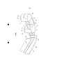
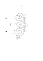
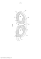
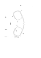
DISPOSITIVO INTERCORPORAL Um dispositivo intercorporal (10) para substituir um disco entre e/ou fundir vértebras adjacentes compreendendo: uma pluralidade de tambores espaçados (30) conectados uns aos outros por uma única ponte flexível (60).INTERCORPORAL DEVICE An intercorporeal device (10) for replacing a disc between and / or fusing adjacent vertebrae comprising: a plurality of spaced drums (30) connected to each other by a single flexible bridge (60).
Description
[0001] Este pedido de patente internacional reivindica o benefício do pedido de patente copendente provisório número de série U.S. 61/224.333 depositado em 9 de julho de 2009 e intitulado “Sistema e Método de Inserção Intercorporal Aprimorados”.[0001] This international patent application claims the benefit of provisional copending patent application serial number U.S. 61 / 224,333 filed on July 9, 2009 and entitled “Enhanced Intercorporeal Insertion System and Method”.
[0002] A presente invenção refere-se em, em geral, a um dispositivo intercorporal para substituição de disco intervertebral ou fusão espinhal intercorporal e mais especificamente a um sistema que inclui um dispositivo para substituição de disco ou um dispositivo intercorporal para fusão espinhal e um sistema e método de inserção para colocar os dispositivos previamente mencionados em um espaço intervertebral com o uso de uma pluralidade de abordagens cirúrgicas.[0002] The present invention relates, in general, to an intercorporeal device for intervertebral disc replacement or intercorporeal spinal fusion and more specifically to a system including a disc replacement device or an intercorporeal device for spinal fusion and a insertion system and method for placing previously mentioned devices in an intervertebral space using a plurality of surgical approaches.
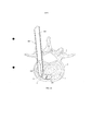
[0003] A espinha humana normal é compreendida de sete vértebras cervicais, doze torácicas, e cinco lombares. Discos intervertebrais são dispostos entre vértebras adjacentes com a exceção das duas primeiras vértebras cervicais. As vértebras espinhais são suportadas por ligamentos, tendões e músculos que permitem movimentos como flexão, extensão, rotação e curvamento lateral.[0003] The normal human spine is comprised of seven cervical, twelve thoracic, and five lumbar vertebrae. Intervertebral discs are placed between adjacent vertebrae with the exception of the first two cervical vertebrae. Spinal vertebrae are supported by ligaments, tendons and muscles that allow movements such as flexion, extension, rotation and lateral curvature.
[0004] O movimento entre vértebras ocorre através de movimento relativo do disco e duas juntas facetárias. O disco repousa na porção frontal ou anterior da espinha. As juntas facetárias repousam lateralmente em cada lado da porção posterior da espinha. O formato básico de um disco intervertebral humano é oval, com uma depressão em um lado longitudinal do mesmo para criar um formato de feijão.[0004] The movement between vertebrae occurs through relative movement of the disc and two facet joints. The disc rests on the front or front of the spine. The facet joints rest laterally on each side of the posterior portion of the spine. The basic shape of a human intervertebral disc is oval, with a depression on one longitudinal side of it to create a bean shape.
[0005] A espinha é uma estrutura flexível que é capaz de grande curvatura e torção em uma pluralidade de direções. Entretanto, irregularidades genéticas ou de desenvolvimento, trauma, estresse crônico e degeneração devido ao desgaste podem resultar na necessidade por intervenção cirúrgica para efetivar reparo. Em casos de degeneração (ou lesão e doença) pode ser necessário ou desejável remover um disco que já não mais desempenha a função de separação entre vértebras adjacentes. Isto é particularmente desejável em casos de degeneração ou herniação, que muitas vezes resultam em dor nas costas crônica e debilitante.[0005] The spine is a flexible structure that is capable of great curvature and torsion in a plurality of directions. However, genetic or developmental irregularities, trauma, chronic stress and degeneration due to wear and tear can result in the need for surgical intervention to effect repair. In cases of degeneration (or injury and illness) it may be necessary or desirable to remove a disc that no longer performs the function of separating adjacent vertebrae. This is particularly desirable in cases of degeneration or herniation, which often results in chronic and debilitating back pain.
[0006] Um disco danificado pode ser substituído com um disco protético que se destina a ser funcionalmente idêntico ao disco natural. Alguns discos de substituição da técnica anterior são formatados para se aproximar do formato do disco natural que é substituído, e são adicionalmente compreendidos de um material flexível que tem uma memória de formato de modo que o disco pode ser deformado para inserção através de uma área pequena na espinha, então se expande para seu formato normal uma vez que a inserção é completada. Uma das maiores dificuldades com muitos discos da técnica anterior é que eles são, em sua maior parte, facilmente inseridos com o uso de uma inserção cirúrgica anterior devido à estrutura da espinha e à disposição de nervos próximos à espinha. A abordagem cirúrgica anterior da substituição de disco é, entretanto, muito invasiva.[0006] A damaged disc can be replaced with a prosthetic disc that is intended to be functionally identical to the natural disc. Some prior art replacement discs are formatted to approximate the shape of the natural disc being replaced, and are additionally comprised of a flexible material that has a shape memory so that the disc can be deformed for insertion through a small area on the spine, then expands to its normal shape once the insertion is completed. One of the greatest difficulties with many prior art discs is that they are, for the most part, easily inserted using an anterior surgical insertion due to the structure of the spine and the disposition of nerves close to the spine. The previous surgical approach to disc replacement is, however, very invasive.
[0007] Além disso, muitas substituições de discos da técnica anterior são dispositivos complexos feitos de uma combinação de materiais e são também volumosos e difíceis de colocar de modo apropriado entre vértebras adjacentes. A implantação destes dispositivos da técnica anterior exige cirurgia invasiva para colocação apropriada. Adicionalmente, algumas substituições de discos utilizam materiais como hidrogéis para simular a textura gelatinosa do núcleo do disco natural. Entretanto, estes materiais tendem a ser facilmente danificados durante a implantação e também tendem a migrar em áreas indesejadas do corpo.[0007] In addition, many prior art disc replacements are complex devices made from a combination of materials and are also bulky and difficult to place properly between adjacent vertebrae. The implantation of these prior art devices requires invasive surgery for proper placement. In addition, some disc replacements use materials such as hydrogels to simulate the gelatinous texture of the natural disc core. However, these materials tend to be easily damaged during implantation and also tend to migrate to unwanted areas of the body.
[0008] Inúmeros dispositivos intercorporais da técnica anterior para efetuar a fusão de vértebras adjacentes entre si são também empregadas para aliviar a dor e desconforto causado pela degeneração de disco. A implantação destes dispositivos da técnica anterior é tipicamente muito incômoda e invasiva devido primeiramente a sua estrutura complexa e a geometria complexa da espinha humana.[0008] Numerous prior-art intercorporeal devices for fusing adjacent vertebrae together are also used to relieve pain and discomfort caused by disc degeneration. The implantation of these prior art devices is typically very uncomfortable and invasive due primarily to their complex structure and the complex geometry of the human spine.
[0009] Consequentemente, existe a necessidade de um dispositivo de disco intercorporal ou um dispositivo de substituição de disco e um sistema de implantação para inserir dispositivo de substituição de disco ou fusão intercorporal que são robustos e cirurgicamente minimamente invasivo para a substituição eficaz de discos intervertebrais danificados ou degenerados.[0009] Consequently, there is a need for an intercorporeal disc device or disc replacement device and an implantation system to insert disc replacement or intercorporal fusion device that are robust and surgically minimally invasive for the effective replacement of intervertebral discs damaged or degenerated.
[00010] A presente invenção elimina as dificuldades previamente mencionadas na técnica anterior ao fornecer um dispositivo intercorporal aprimorado se aproxima um pouco mais da semelhança da fisiologia do disco natural e ao fornecer um sistema e método para posicionar dispositivos intercorporais aprimorados que habilita um cirurgião a colocar de modo preciso e rápido um dispositivo intercorporal de tamanho apropriado em um espaço de disco, com isso minimizando o tempo de cirurgia e aprimorando em muito o tempo de recuperação para cirurgias de substituição de disco.[00010] The present invention eliminates the difficulties previously mentioned in the prior art in providing an improved intercorporeal device is a little closer to the similarity of the physiology of the natural disk and in providing a system and method for positioning enhanced intercorporeal devices that enables a surgeon to place accurately and quickly an appropriately sized intercorporeal device in a disk space, thereby minimizing surgery time and greatly improving recovery time for disk replacement surgeries.
[00011] Os dispositivos intercorporais aprimorados da presente invenção compreendem uma pluralidade de tambores, ou geralmente corpos anulares, que se estendem a partir de uma ponte flexível que permite que os tambores flexionem-se independentemente e comprimem juntas para posicionamento fácil em dito espaço de disco, enquanto relaxam para seu formato natural uma vez posicionadas. As tambores podem incluir, ainda, uma pluralidade de aberturas para aceitar material de enxerto ósseo para auxiliar no processo de fusão, assim como superfícies enrugadas superior e inferior que agem para guiar os dispositivos intercorporais quando da entrada no espaço de disco e engatam as vértebras adjacentes.[00011] The enhanced intercorporeal devices of the present invention comprise a plurality of drums, or generally annular bodies, that extend from a flexible bridge that allows the drums to flex independently and compress together for easy positioning in said disk space , while relaxing to their natural shape once positioned. Drums can also include a plurality of openings for accepting bone graft material to aid in the fusion process, as well as wrinkled upper and lower surfaces that act to guide intercorporeal devices when entering disc space and engaging adjacent vertebrae. .
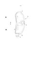
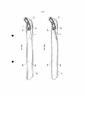
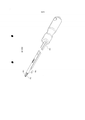
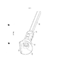
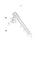
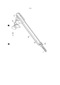
[00012] O sistema de inserção intercorporal da presente invenção inclui um tubo insersor que é formatado para guiar uma pluralidade de instrumentos no espaço de disco na mesma orientação durante todo o processo. Uma vez inserido, o tubo insersor pode ser preso à espinha por meio de um braço de extensão que trava o tubo no lugar. Uma pluralidade de instrumentos de borda arredondada que tem pontas distais de formatos variados são usados para preparar o espaço de disco para a entrada do dispositivo intercorporal, assim como para auxiliar na inserção do dispositivo intercorporal no espaço de disco.[00012] The intercorporeal insertion system of the present invention includes an insertion tube that is shaped to guide a plurality of instruments in the disc space in the same orientation throughout the process. Once inserted, the insertion tube can be attached to the spine by means of an extension arm that locks the tube in place. A plurality of rounded-edge instruments having distal tips of varying shapes are used to prepare the disk space for entry of the intercorporeal device, as well as to assist in the insertion of the intercorporeal device into the disk space.
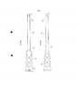
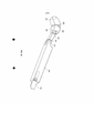
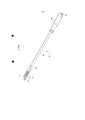
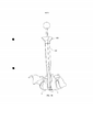
[00013] Adicionalmente, o sistema da presente invenção inclui uma pluralidade de implantes de teste de articulação que podem ser inseridos para determinar o comprimento de implante apropriado antes de posicionar um dispositivo intercorporal. Os implantes de teste da invenção podem articular com respeito a uma haste de implante que auxilia no posicionamento dos mesmos no espaço de disco, fornecendo com isso inserção e remoção de teste relativamente fácil.[00013] In addition, the system of the present invention includes a plurality of joint test implants that can be inserted to determine the appropriate implant length before positioning an intercorporeal device. The test implants of the invention can articulate with respect to an implant stem that assists in positioning them in the disk space, thereby providing relatively easy test insertion and removal.
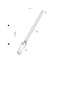
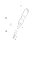
[00014] A invenção compreende, ainda, um cabo de tubo insersor inovador que é capaz de ser preso a um cabo complementar que afixiona a uma pluralidade de instrumentos de borda arredondada para inserção no espaço de disco. Um cortador em caixa que tem uma ponta distal com bordas de corte opostas é fornecido para raspar as placas terminais posteriores de vértebras adjacentes ao preparar para a inserção de implante.[00014] The invention further comprises an innovative insertion tube cable that is capable of being attached to a complementary cable that attaches to a plurality of rounded edge instruments for insertion into the disk space. A box cutter that has a distal tip with opposite cutting edges is provided to scrape the posterior end plates of adjacent vertebrae when preparing for implant insertion.
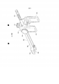
[00015] A invenção também inclui um sistema de inserção de enxerto ósseo que utiliza um êmbolo de enxerto ósseo inovador para distribuir material moserlizado de enxerto ósseo através do espaço de disco anterior.[00015] The invention also includes a bone graft insertion system that uses an innovative bone graft plunger to deliver bone graft graft material through the anterior disc space.
[00016] Outros recursos, vantagens, e objetivos da presente invenção se tornarão mais aparentes a partir da descrição detalhada da invenção no presente documento, abaixo, tomados em conjunção com as Figuras desenhadas em anexo. BREVE DESCRIÇÃO DAS FIGURAS DESENHADAS A Figura 1 é uma vista em perspectiva de um dispositivo intercorporal e um tubo insersor de acordo com uma modalidade da presente invenção; A Figura 2 é uma vista em perspectiva de um dispositivo intercorporal e um tubo insersor de acordo com uma modalidade da presente invenção; A Figura 3 é uma vista em perspectiva de um dispositivo intercorporal e um tubo insersor de acordo com uma modalidade da presente invenção; A Figura 4 é uma vista superior de um dispositivo intercorporal de acordo com uma modalidade da presente invenção; A Figura 5 é uma vista superior de um dispositivo intercorporal de acordo com uma modalidade da presente invenção; A Figura 6 é uma vista superior de um dispositivo intercorporal de acordo com uma modalidade da presente invenção. A Figura 7 é uma vista superior de um dispositivo intercorporal de acordo com uma modalidade da presente invenção; A Figura 8 é uma vista superior de um dispositivo intercorporal de acordo com uma modalidade da presente invenção; A Figura 9 é uma vista em perspectiva de um dispositivo intercorporal de acordo com uma modalidade da presente invenção; A Figura 10 é uma vista em perspectiva de um dispositivo intercorporal de acordo com uma modalidade da presente invenção; A Figura 11 é uma vista superior de um dispositivo intercorporal de acordo com uma modalidade da presente invenção; A Figura 12 é uma vista superior de um dispositivo intercorporal de acordo com uma modalidade da presente invenção; A Figura 13 é uma vista superior de um dispositivo intercorporal de acordo com uma modalidade da presente invenção; A Figura 14 é uma vista em perspectiva de um dispositivo intercorporal de acordo com uma modalidade da presente invenção; A Figura 15 é uma vista em perspectiva de um dispositivo intercorporal de acordo com uma modalidade da presente invenção; A Figura 16 é uma vista em perspectiva de um dispositivo intercorporal de acordo com uma modalidade da presente invenção; A Figura 17 é uma vista superior de um dispositivo intercorporal de acordo com uma modalidade da presente invenção; A Figura 18 é uma vista superior de um dispositivo intercorporal de acordo com uma modalidade da presente invenção; A Figura 19 é uma vista superior de um dispositivo intercorporal ao avançar em um espaço de disco de acordo com uma modalidade da presente invenção; A Figura 20 é uma vista em perspectiva de uma haste impulsora de dispositivo intercorporal de acordo com uma modalidade da presente invenção; A Figura 21 é uma vista em perspectiva de uma ferramenta de inserção de acordo com uma modalidade da presente invenção; A Figura 22 é uma vista explodida de uma ferramenta de inserção de acordo com uma modalidade da presente invenção; A Figura 23 é uma vista em perspectiva de um implante de teste de acordo com uma modalidade da presente invenção; A Figura 24 é uma vista em perspectiva de uma borda arredondada e cabo de teste de acordo com uma modalidade da presente invenção; A Figura 25 é uma vista parcial de uma borda arredondada e insersor de acordo com uma modalidade da presente invenção; A Figura 26 é uma vista em perspectiva de um implante de teste de acordo com uma modalidade da presente invenção; A Figura 27 é uma vista parcial de uma borda arredondada e insersor de acordo com uma modalidade da presente invenção; A Figura 28 é uma vista explodida de uma borda arredondada e cabo de teste de acordo com uma modalidade da presente invenção; A Figura 29 é uma vista em perspectiva de um cabo de teste e borda arredondada montados em um tubo insersor de acordo com uma modalidade da presente invenção; A Figura 30 é uma vista lateral de um tubo insersor de acordo com uma modalidade da presente invenção; A Figura 31 é uma vista lateral de um tubo insersor de acordo com uma modalidade da presente invenção; A Figura 32 é uma vista em perspectiva de um implante de teste e cabo de teste de acordo com uma modalidade da presente invenção; A Figura 33 é uma vista lateral de um implante de teste de acordo com uma modalidade da presente invenção; A Figura 34 é uma vista em perspectiva de um cabo de teste de acordo com uma modalidade da presente invenção; A Figura 35 é uma vista explodida de um cabo de teste de acordo com uma modalidade da presente invenção; A Figura 36 é uma vista em perspectiva de um implante de teste e haste de implante de acordo com uma modalidade da presente invenção; A Figura 37 é uma vista em perspectiva de um implante de teste de acordo com uma modalidade da presente invenção; A Figura 38 é uma vista superior de um tubo insersor e implante de teste ao avançar em um espaço de disco de acordo com uma modalidade da presente invenção; A Figura 39 é uma vista superior de um tubo insersor e implante de teste ao avançar em um espaço de disco de acordo com uma modalidade da presente invenção; A Figura 40 é uma vista superior de um tubo insersor e implante de teste ao avançar em um espaço de disco de acordo com uma modalidade da presente invenção; A Figura 41 é uma vista superior de um tubo insersor e implante de teste ao avançar em um espaço de disco de acordo com uma modalidade da presente invenção; A Figura 42 é uma vista superior de um tubo insersor e implante de teste ao avançar em um espaço de disco de acordo com uma modalidade da presente invenção; A Figura 43 é uma vista superior de um tubo insersor e implante de teste ao avançar em um espaço de disco de acordo com uma modalidade da presente invenção; A Figura 44 é uma vista lateral parcial de um dispositivo intercorporal e borda arredondada dentro de um tubo insersor de acordo com uma modalidade da presente invenção; A Figura 45 é uma vista lateral parcial de um dispositivo intercorporal e borda arredondada dentro de um tubo insersor de acordo com uma modalidade da presente invenção; A Figura 46 é uma vista parcial superior de uma borda arredondada de acordo com uma modalidade da presente invenção; A Figura 47 é uma vista parcial inferior de uma borda arredondada de acordo com uma modalidade da presente invenção; A Figura 48 é uma vista parcial superior de uma borda arredondada de acordo com uma modalidade da presente invenção; A Figura 49 é uma vista parcial inferior de uma borda arredondada de acordo com uma modalidade da presente invenção; A Figura 50 é uma vista superior de um tubo insersor em um espaço de disco, com um dispositivo intercorporal e borda arredondada ao avançar em dito espaço de disco de acordo com uma modalidade da presente invenção; A Figura 51 é uma vista superior de um tubo insersor em um espaço de disco, com um dispositivo intercorporal e borda arredondada ao avançar em dito espaço de disco de acordo com uma modalidade da presente invenção; A Figura 52 é uma vista superior de um tubo insersor em um espaço de disco, com um dispositivo intercorporal e borda arredondada ao avançar em dito espaço de disco de acordo com uma modalidade da presente invenção; A Figura 53 é uma vista em perspectiva de um cortador em caixa de acordo com uma modalidade da presente invenção; A Figura 54 é uma vista lateral de um cortador em caixa de acordo com uma modalidade da presente invenção; A Figura 55 é uma vista lateral de um tubo insersor avançado em um espaço de disco de acordo com uma modalidade da presente invenção; A Figura 56 é uma vista em perspectiva de um cabo de teste e uma borda arredondada de acordo com uma modalidade da presente invenção; A Figura 57 é uma vista em perspectiva de um cabo de teste e uma borda arredondada de acordo com uma modalidade da presente invenção; A Figura 58 é uma vista lateral em seção transversal de uma borda arredondada e dispositivo intercorporal avançando através um tubo insersor de acordo com uma modalidade da presente invenção; A Figura 59 é uma vista em perspectiva de uma ferramenta de inserção de dispositivo intercorporal de acordo com uma modalidade da presente invenção; A Figura 60 é uma vista em perspectiva de uma ferramenta de inserção de dispositivo intercorporal de acordo com uma modalidade da presente invenção; A Figura 61 é uma vista em perspectiva de um funil de enxerto ósseo preso a um tubo insersor de acordo com uma modalidade da presente invenção; A Figura 62 é uma vista em perspectiva de um funil de enxerto ósseo de acordo com uma modalidade da presente invenção; A Figura 63 é uma vista em perspectiva de um funil de enxerto ósseo de acordo com uma modalidade da presente invenção; A Figura 64 é uma vista em perspectiva explodida de um êmbolo de enxerto ósseo de acordo com uma modalidade da presente invenção; A Figura 65 é uma vista em perspectiva de um êmbolo de enxerto ósseo de acordo com uma modalidade da presente invenção; A Figura 66 é uma vista em perspectiva de um êmbolo de enxerto ósseo de acordo com uma modalidade da presente invenção; A Figura 67 é uma vista lateral de um êmbolo de enxerto ósseo de acordo com uma modalidade da presente invenção; A Figura 68 é uma vista em perspectiva de um êmbolo de enxerto ósseo de acordo com uma modalidade da presente invenção; A Figura 69 é uma vista lateral em seção transversal de um êmbolo de enxerto ósseo avançando através um tubo insersor em um espaço de disco de acordo com uma modalidade da presente invenção; A Figura 70 é uma vista lateral de um êmbolo de enxerto ósseo avançando através um tubo insersor em um espaço de disco de acordo com uma modalidade da presente invenção; A Figura 71 é uma vista lateral em seção transversal de um êmbolo de enxerto ósseo avançando através um tubo insersor de acordo com uma modalidade da presente invenção; A Figura 72 é uma vista em perspectiva de um braço de extensão de acordo com uma modalidade da presente invenção; A Figura 73 é uma vista lateral de um braço de extensão de acordo com uma modalidade da presente invenção; A Figura 74 é uma vista em perspectiva de um braço de extensão de acordo com uma modalidade da presente invenção; A Figura 75 é uma vista em perspectiva de um braço de extensão de acordo com uma modalidade da presente invenção; A Figura 76 é uma vista em perspectiva de um braço de extensão de acordo com uma modalidade da presente invenção; A Figura 77 é uma vista em perspectiva de um braço de extensão de acordo com uma modalidade da presente invenção; A Figura 78 é uma vista em perspectiva de um braço de extensão de acordo com uma modalidade da presente invenção; A Figura 79 é uma vista em perspectiva de um braço de extensão de acordo com uma modalidade da presente invenção; A Figura 80 é uma vista em perspectiva do sistema da presente invenção no lugar no ambiente de uma espinha humana de acordo com uma modalidade da presente invenção.[00016] Other features, advantages, and objectives of the present invention will become more apparent from the detailed description of the invention in the present document, below, taken in conjunction with the Figures drawn in the annex. BRIEF DESCRIPTION OF THE DRAWN FIGURES Figure 1 is a perspective view of an intercorporeal device and an insertion tube according to an embodiment of the present invention; Figure 2 is a perspective view of an intercorporeal device and an insertion tube according to an embodiment of the present invention; Figure 3 is a perspective view of an intercorporeal device and an insertion tube according to an embodiment of the present invention; Figure 4 is a top view of an intercorporeal device according to an embodiment of the present invention; Figure 5 is a top view of an intercorporeal device according to an embodiment of the present invention; Figure 6 is a top view of an intercorporeal device according to an embodiment of the present invention. Figure 7 is a top view of an intercorporeal device according to an embodiment of the present invention; Figure 8 is a top view of an intercorporeal device according to an embodiment of the present invention; Figure 9 is a perspective view of an intercorporeal device according to an embodiment of the present invention; Figure 10 is a perspective view of an intercorporeal device according to an embodiment of the present invention; Figure 11 is a top view of an intercorporeal device according to an embodiment of the present invention; Figure 12 is a top view of an intercorporeal device according to an embodiment of the present invention; Figure 13 is a top view of an intercorporeal device according to an embodiment of the present invention; Figure 14 is a perspective view of an intercorporeal device according to an embodiment of the present invention; Figure 15 is a perspective view of an intercorporeal device according to an embodiment of the present invention; Figure 16 is a perspective view of an intercorporeal device according to an embodiment of the present invention; Figure 17 is a top view of an intercorporeal device according to an embodiment of the present invention; Figure 18 is a top view of an intercorporeal device according to an embodiment of the present invention; Figure 19 is a top view of an intercorporeal device when advancing into a disk space in accordance with an embodiment of the present invention; Figure 20 is a perspective view of an impeller of an intercorporeal device according to an embodiment of the present invention; Figure 21 is a perspective view of an insertion tool according to an embodiment of the present invention; Figure 22 is an exploded view of an insertion tool according to an embodiment of the present invention; Figure 23 is a perspective view of a test implant according to an embodiment of the present invention; Figure 24 is a perspective view of a rounded edge and test cable in accordance with an embodiment of the present invention; Figure 25 is a partial view of a rounded edge and inserter according to an embodiment of the present invention; Figure 26 is a perspective view of a test implant according to an embodiment of the present invention; Figure 27 is a partial view of a rounded edge and inserter according to an embodiment of the present invention; Figure 28 is an exploded view of a rounded edge and test cable in accordance with an embodiment of the present invention; Figure 29 is a perspective view of a test cable and rounded edge mounted on an insertion tube in accordance with an embodiment of the present invention; Figure 30 is a side view of an insertion tube according to an embodiment of the present invention; Figure 31 is a side view of an insertion tube according to an embodiment of the present invention; Figure 32 is a perspective view of a test implant and test cable in accordance with an embodiment of the present invention; Figure 33 is a side view of a test implant according to an embodiment of the present invention; Figure 34 is a perspective view of a test cable in accordance with an embodiment of the present invention; Figure 35 is an exploded view of a test cable in accordance with an embodiment of the present invention; Figure 36 is a perspective view of a test implant and implant stem in accordance with an embodiment of the present invention; Figure 37 is a perspective view of a test implant according to an embodiment of the present invention; Figure 38 is a top view of an insertion tube and test implant when advancing into a disc space in accordance with an embodiment of the present invention; Figure 39 is a top view of an insertion tube and test implant when advancing into a disc space in accordance with an embodiment of the present invention; Figure 40 is a top view of an insertion tube and test implant when advancing into a disc space in accordance with an embodiment of the present invention; Figure 41 is a top view of an insertion tube and test implant when advancing into a disc space in accordance with an embodiment of the present invention; Figure 42 is a top view of an insertion tube and test implant when advancing into a disc space in accordance with an embodiment of the present invention; Figure 43 is a top view of an insertion tube and test implant when advancing into a disc space in accordance with an embodiment of the present invention; Figure 44 is a partial side view of an intercorporeal device and a rounded edge within an insertion tube according to an embodiment of the present invention; Figure 45 is a partial side view of an intercorporeal device and a rounded edge within an insertion tube according to an embodiment of the present invention; Figure 46 is a partial top view of a rounded edge according to an embodiment of the present invention; Figure 47 is a partial bottom view of a rounded edge according to an embodiment of the present invention; Figure 48 is a partial top view of a rounded edge according to an embodiment of the present invention; Figure 49 is a partial bottom view of a rounded edge according to an embodiment of the present invention; Figure 50 is a top view of an insertion tube in a disk space, with an intercorporeal device and a rounded edge when advancing in said disk space according to an embodiment of the present invention; Figure 51 is a top view of an insertion tube in a disc space, with an intercorporeal device and a rounded edge when advancing in said disc space according to an embodiment of the present invention; Figure 52 is a top view of an insertion tube in a disc space, with an intercorporeal device and a rounded edge when advancing in said disc space according to an embodiment of the present invention; Figure 53 is a perspective view of a box cutter according to an embodiment of the present invention; Figure 54 is a side view of a box cutter according to an embodiment of the present invention; Figure 55 is a side view of an advanced insertion tube in a disc space according to an embodiment of the present invention; Figure 56 is a perspective view of a test cable and a rounded edge according to an embodiment of the present invention; Figure 57 is a perspective view of a test cable and a rounded edge according to an embodiment of the present invention; Figure 58 is a cross-sectional side view of a rounded edge and intercorporeal device advancing through an insertion tube according to an embodiment of the present invention; Figure 59 is a perspective view of an intercorporeal device insertion tool according to an embodiment of the present invention; Figure 60 is a perspective view of an intercorporeal device insertion tool according to an embodiment of the present invention; Figure 61 is a perspective view of a bone graft funnel attached to an insertion tube according to an embodiment of the present invention; Figure 62 is a perspective view of a bone graft funnel according to an embodiment of the present invention; Figure 63 is a perspective view of a bone graft funnel according to an embodiment of the present invention; Figure 64 is an exploded perspective view of a bone graft plunger according to an embodiment of the present invention; Figure 65 is a perspective view of a bone graft plunger according to an embodiment of the present invention; Figure 66 is a perspective view of a bone graft plunger according to an embodiment of the present invention; Figure 67 is a side view of a bone graft plunger according to an embodiment of the present invention; Figure 68 is a perspective view of a bone graft plunger according to an embodiment of the present invention; Figure 69 is a cross-sectional side view of a bone graft plunger advancing through an insertion tube into a disc space in accordance with an embodiment of the present invention; Figure 70 is a side view of a bone graft plunger advancing through an insertion tube into a disc space in accordance with an embodiment of the present invention; Figure 71 is a cross-sectional side view of a bone graft plunger advancing through an insertion tube according to an embodiment of the present invention; Figure 72 is a perspective view of an extension arm according to an embodiment of the present invention; Figure 73 is a side view of an extension arm according to an embodiment of the present invention; Figure 74 is a perspective view of an extension arm according to an embodiment of the present invention; Figure 75 is a perspective view of an extension arm according to an embodiment of the present invention; Figure 76 is a perspective view of an extension arm according to an embodiment of the present invention; Figure 77 is a perspective view of an extension arm according to an embodiment of the present invention; Figure 78 is a perspective view of an extension arm according to an embodiment of the present invention; Figure 79 is a perspective view of an extension arm according to an embodiment of the present invention; Figure 80 is a perspective view of the system of the present invention in place in the environment of a human spine according to an embodiment of the present invention.
[00017] Referindo-se agora às Figuras desenhadas, e em particular as Figuras 1 a 3, e de acordo com uma modalidade construída preferencial do sistema 10 da presente invenção, é retratado um dispositivo intercorporal 20 e um tubo insersor 100 para orientar e inserir dito dispositivo intercorporal 20 em um espaço de disco de uma espinha humana. As Figuras desenhadas 50 e 55 retratam um exemplo da inserção do dispositivo intercorporal 20 em um espaço de disco 2 de uma espinha 1 entre vértebras 4, e pode ser referido por toda esta especificação a título de referência à anatomia do corpo humano ao qual a presente invenção é aplicada. Além disso, deve-se notar que o disco a ser substituído pelo dispositivo intercorporal 20 da presente invenção é primeiro removido por um cirurgião que desempenha uma discectomia completa. Tipicamente, é desejável estender a discectomia para uma metade contralateral do espaço de disco para permitir a colocação do dispositivo intercorporal mais longo 20 possível e para maximizar a exposição de superfície óssea para que a fusão ocorra. Caso haja colapso de espaço de disco 2 significativo, uma discectomia completa pode não ser possível até que a dispersão de espaço de disco 2 seja desempenhada com o uso de uma das muitas ferramentas de dispersão conhecidas na técnica.[00017] Referring now to the Figures drawn, and in particular Figures 1 to 3, and according to a preferred constructed embodiment of the
[00018] Conforme visto na Figura 1, o dispositivo intercorporal 20 pode compreender uma pluralidade de ressaltos ou tambores 30, cada um espaçado um do outro e pende a partir de uma ponte flexível 60 que permite dobramento e movimento de cada tambor 30 para facilitar a entrada no espaço de disco 2. A ponte flexível 60 pode ser compreendida de um metal com memória como nitinol ou outros materiais plásticos que tem memória de formato de modo que o formato total do dispositivo intercorporal 20 seja retido uma vez que o dispositivo 20 é implantado. Nas modalidades da invenção retratadas nas Figuras 1 a 3 cada tambor 30 inclui um par de passagens geralmente paralelas 32 na mesma, através das quais uma sutura 3 pode ser rosqueada para auxiliar no posicionamento do dispositivo intercorporal 20, assim como para habilitar a recuperação do dispositivo 20 caso sua colocação se torne insatisfatória. Uma vez dispositivo intercorporal 20 é de modo apropriado inseridos no espaço de disco 2, a sutura 3 pode ser manipulada para auxiliar no posicionamento do implante ao puxar em cada extremidade do mesmo. Uma vez que o dispositivo 20 é posicionado de modo apropriado, a sutura 3 pode ser simplesmente puxada através de ambas as passagens 32 e, então, removida do dispositivo intercorporal 20.[00018] As seen in Figure 1, the
[00019] Os tambores 30 do dispositivo intercorporal 20 podem compreender, ainda, uma superfície superior 34 e uma superfície inferior 36 que entra em contato com superfícies superior e inferior das vértebras adjacentes 4 uma vez que o dispositivo intercorporal 20 é posicionado de modo apropriado no espaço de disco 2. O dispositivo intercorporal 20 pode compreender, ainda, uma parede anterior 40 que pode ser integral com a ponte 60, e pode ser geralmente convexa em formato. A parede anterior 40 pode terminar em tambores distal e proximal 30. A parede anterior 40 inclui uma porção de parede interior 42 que se estende entre tambores adjacentes 30. Adicionalmente, cada tambor 30 inclui uma parede posterior 44 que se estende geralmente entre porções superior 34 e inferior 36 dos tambores 30 em uma porção posterior do mesmo.[00019] The
[00020] Embora muitas modalidades do dispositivo intercorporal 20 da presente invenção sejam mostradas para ter uma curvatura geralmente anterior, deve-se reconhecer que dispositivos intercorporais 20 que tem uma curvatura posterior estão dentro do escopo da presente invenção. Adicionalmente, o dispositivo intercorporal 20 é preferencialmente formado a partir de um material que é durável e não reativo. Uma ampla variedade de materiais biocompatíveis pode ser utilizada para fabricar o dispositivo intercorporal 20 da presente invenção, que inclui, mas não se limita a polímeros biocompatíveis, materiais elastoméricos, hidrogéis, polímeros hidrófilos, polímeros com memória de formato, e metais com memória de formato. Entende-se que uma pessoa com habilidade comum na técnica estaria ciente de uma variedade de materiais adequados para tal implantação. Em uma modalidade da invenção, o dispositivo intercorporal 20 é compreendido de um material de fibra de carbono enquanto em outro, o dispositivo 20 é compreendido de um material de polietercetona (PEK).[00020] Although many embodiments of the
[00021] Conforme mostrado na Figura 1, o tambor proximal 30 pode incluir um engate 50, retratado nesta modalidade da invenção como uma protrusão geralmente anular que se estende para fora a partir do tambor proximal 30, que pode ser captado ou preso em diversas ferramentas de inserção conforme será discutido em maiores detalhes no presente documento, abaixo.[00021] As shown in Figure 1, the
[00022] As Figuras 1 a 3 também retratam um tubo insersor 100 mostrado com uma parede removida para mostrar a trajetória da sutura 3 através do tubo de inserção 100. O tubo de inserção 100 compreende um par de paredes opostas superior e inferior 102, 104 e paredes opostas central e lateral 106, 108 que definem um membro tubular oco através do qual o dispositivo intercorporal 20 pode ser posicionado. O tubo de inserção 100 inclui uma extremidade distai 110 em que a parede lateral 108 forma uma porção curvada 112 que guia o posicionamento do dispositivo intercorporal 20 conforme o mesmo é avançado através do tubo de inserção 100. Nesta modalidade da presente invenção, a porção curvada 112 da parede lateral 108 tem um comprimento maior do que o da parede central 106 para permitir que o dispositivo intercorporal 20 curve no espaço de disco 2 conforme o mesmo é avançado através do tubo de inserção 100.[00022] Figures 1 to 3 also depict an
[00023] Os tambores 30 de cada dispositivo intercorporal 20 são espaçados de modo que uma área de alívio 38 é definida pelo espaço vazio entre tambores 30. A área de alívio 38 permite que o dispositivo intercorporal 20 e tambores 30 flexionem e comprimam durante a inserção e colocação no espaço de disco 2 enquanto retornam para seu formato relaxado uma vez que o mesmo é posicionado de modo apropriado. A Figura 2 retrata um dispositivo intercorporal 20 que tem apenas dois tambores 30, com isso fornecendo uma área de alívio muito maior 38. A Figura 3 retrata um dispositivo intercorporal 20 em que a sutura 3 é amarrada em uma extremidade terminal para a recuperação do dispositivo 20 de volta através do tubo de inserção 100.[00023] The
[00024] A Figura 4 é uma vista superior de uma modalidade da presente invenção segundo a qual cada tambor 30 do dispositivo intercorporal 20 inclui uma abertura 46 no mesmo para aceitar um material moserlizado de enxerto ósseo para aprimorar o processo de fusão espinhal. Adicionalmente, conforme visto na Figura 4 um engate 50 pode compreender uma abertura geralmente anular 52 no mesmo para aceitar um pino (não mostrado) ou outro instrumento para inserir, recuperar e posicionar o dispositivo intercorporal 20 no espaço de disco 2.[00024] Figure 4 is a top view of an embodiment of the present invention according to which each drum 30 of the
[00025] As Figuras 5 e 6 retratam uma modalidade adicional da presente invenção segundo a qual a porção de alívio 38 do dispositivo intercorporal 20 próxima à parede interior 42 define uma fenda alongada que habilita a flexão da ponte 60 enquanto cada tambor 30 flexiona independentemente dos outros e é capaz de moções em três planos. Este recurso da invenção habilita posicionamento preciso do dispositivo 20 no espaço de disco 2 ao permitir que o dispositivo 20 deforme durante a inserção no espaço de disco 2 e expande de volta para seu formato relaxado uma vez inserido de modo apropriado. A modalidade da invenção mostrada na Figura 5 retrata superfícies superiores 34 que tem uma pluralidade de cristas corrugadas 33 nas mesmas. Superfícies inferiores 36 podem também incluir uma pluralidade de cristas corrugadas 33 para permitir que o dispositivo intercorporal 20 engate as superfícies superior e inferior das vértebras adjacentes quando inserido no espaço de disco 2, que também ajuda o posicionamento do dispositivo 20 dentro do espaço de disco 2.[00025] Figures 5 and 6 depict an additional embodiment of the present invention according to which the
[00026] A Figura 7 retrata uma modalidade ainda adicional do dispositivo intercorporal 20 segundo a qual a ponte flexível 60 é presa em um par de tambores opostos 30, sendo que aquele proximal inclui um engate 50 que pende do mesmo para facilitar a inserção e remoção. A Figura 8 retrata uma modalidade similar àquela da Figura 7 em que a ponte flexível 60 se estende em torno da parede posterior 44 do tambor 30 para prender de modo firme o tambor 30 na ponte 60 enquanto ainda permite movimentos independentes de cada tambor 30.[00026] Figure 7 depicts an even further modality of the
[00027] A Figura 9 mostra uma modalidade exemplificativa adicional do dispositivo intercorporal 20 que tem um par de pontes flexíveis opostas espaçadas 60, cada uma presa em um par de tambores espaçados 30 que fornecem uma área de alívio relativamente grande 38. Nesta modalidade da invenção, um engate 50 é fornecido com um par de flanges espaçados 54 que se estende a partir do tambor proximal 30, cada um com uma abertura 52 no mesmo para aceitar um pino (não mostrado) para conectar o dispositivo intercorporal 20 em uma ferramenta de inserção e remoção conforme será discutido em maiores detalhes no presente documento, abaixo.[00027] Figure 9 shows an additional exemplary embodiment of the
[00028] Referindo-se agora às Figuras 10 a 14, é retratada uma pluralidade de dispositivos intercorporais de articulação 200 de acordo com uma modalidade ainda adicional da presente invenção. O dispositivo intercorporal 200 compreende uma metade distai 210 e uma metade proximal 220 conectado por uma dobradiça central 230. Cada metade 210, 220 do implante de teste 200 inclui uma passagem 232 através da qual um segmento de espinha flexível 240 é inserido. A espinha flexível 240 pode ser compreendida de um metal com memória para permitir que metades 210, 200 flexionem entre si e então retornem a uma posição relaxada. Um engate 50 é também fornecido que se estende a partir da metade proximal 220 do implante de teste 200 para facilitar a inserção e remoção do mesmo do espaço de disco 2.[00028] Referring now to Figures 10 to 14, a plurality of
[00029] As Figuras 10 e 11 retratam uma dobradiça central 230 disposta aproximadamente no centro das metades distal e proximal 210, 220, enquanto a Figura 12 retrata a dobradiça 230 disposta nas bordas anteriores das metades distal e proximal 210, 220 para permitir dobramentos na direção anterior. A Figura 13 retrata a dobradiça 230 disposta nas bordas posteriores das metades distal e proximal 210, 220 para permitir dobramentos na direção posterior. Finalmente, a Figura 14 retrata uma modalidade adicional da invenção que tem uma pluralidade de aberturas 234 na mesma para aceitar material de enxerto ósseo para auxiliar na fusão vertebral.[00029] Figures 10 and 11 depict a
[00030] Deve-se notar que as modalidades do dispositivo intercorporal 20 retratadas nas Figuras 10 a 14 podem também ser empregadas como implantes de testes, segundo os quais os mesmos são inseridos no espaço de disco 2 antes da inserção de um implante permanente para testar a adequação do espaço de disco 2 para tamanho e posicionamento apropriado, e para determinar que o espaço de disco 2 esteja preparado para receber de modo apropriado o dispositivo intercorporal 20. Onde os dispositivos intercorporais 20 são empregados como testes, os mesmos podem ser fabricados de um material adequado capaz de reuso após esterilização apropriada, conforme é bem conhecido nas técnicas cirúrgicas.[00030] It should be noted that the modalities of the
[00031] Referindo-se agora às Figuras 15 a 17, uma modalidade exemplificative do dispositivo intercorporal 20 é mostrado formado por uma única peça de material, segundo os quais a ponte flexível 60 é integral com um par de tambores alongadas espaçadas 30, em que cada uma tem superfícies superior 34 e inferior 36 com uma abertura 46 nas mesmas para aceitar material de enxerto ósseo. A modalidade da presente invenção retratada nas Figuras 15 e 17 compreendem, ainda, uma pluralidade de cristas 33 nas superfícies superior 34 e inferior 36 para facilitar o engatamento vertebral do dispositivo 20. Adicionalmente, nesta modalidade da invenção uma porção de um tambor 30 compreende um espaço vazio ou fenda 56 na mesma, que se estendem em torno de uma extremidade de dito tambor 30 e para dentro da parede posterior 44 do mesmo. Adicionalmente, um par de aberturas opostas 58 comunica-se com a fenda 56 para aceitar um pino 59 que é preso nas aberturas 58. O pino 59 pode então ser facilmente acessado através de uma ferramenta de inserção e remoção conforme discutido abaixo.[00031] Referring now to Figures 15 to 17, an exemplary embodiment of the
[00032] Além disso, nesta modalidade da invenção a ponte flexível 60 se estende para fora em direção às extremidades distal e proximal, respectivamente, dos tambores 30 para definir uma área de alívio 38 que permite dobramentos e endireitamento consideráveis do dispositivo 20 conforme a mesma é posicionada através do tubo de inserção 100. Em uma modalidade ainda adicional da invenção, um tambor distai 30 pode compreender uma porção de borda distai chanfrada 31, melhor vista nas Figuras 15 e 16, que facilita a entrada suave do dispositivo 20 no espaço de disco 2 já que a altura dum tambor distai 30 é um pouco menos do que a altura do dispositivo intercorporal 20 ao longo do restante de seu comprimento.[00032] In addition, in this embodiment of the invention the
[00033] Deve-se entender a partir das instruções desta especificação que as modalidades do dispositivo intercorporal 20 mostrado e descrito no presente documento podem ser produzidas em uma ampla variedade de tamanhos, variando tanto em comprimento e altura gerais, assim como variando em espaçamento entre tambores 30 e ponte 60 de modo que a invenção pode ser adaptada para uso em quase qualquer tamanho de espaço de disco conforme exigido por um cirurgião. Além disso, deve-se entender que os dispositivos intercorporais 20 descritos no presente documento podem incluir uma pluralidade de marcadores radiográficos dispostos em uma pluralidade de pontos em ou sobre ditos dispositivos intercorporais 20, para habilitar um cirurgião a garantir colocação adequada de ditos dispositivos 20 através de técnicas radiográficas convencionais.[00033] It should be understood from the instructions in this specification that the modalities of the
[00034] Referindo-se agora à Figura 19 é mostrado uma manga guia de implante flexível 140 que é dimensionada para ser inserida através do tubo de inserção 100 no espaço de disco 2. Nesta modalidade da invenção o dispositivo intercorporal 20 é dotado de uma extremidade distai 142 de manga guia 140 até que a mesma seja posicionada de modo apropriado no espaço de disco 2, então a manga guia 140 é retraída de volta ao tubo de inserção 100. A manga guia 140 pode ser vantajosamente formada de um metal de memória fino ou material flexível equivalente capaz de curvar no espaço de disco 2. Além disso, em uma modalidade da invenção a extremidade distai 142 do formato de manga de guia relaxado 140 aproxima aquela do dispositivo intercorporal 20 e espaço de disco 2 para facilitar a colocação do dispositivo 20 no mesmo.[00034] Referring now to Figure 19, a flexible
[00035] A Figura 20 retrata uma haste impulsora de dispositivo intercorporal 160 adaptada a ser inserida no interior do tubo de inserção 100, que tem um fecho 162 em uma extremidade distai 164 do mesmo. O fecho 162 pode ser ativado através de meios conhecidos na técnica para engatar e liberar um pino 59 de um dispositivo intercorporal 20, por exemplo, o dispositivo 20 retratado na Figura 15. A extremidade distai 164 da haste impulsora 160 pode ser dimensionada para caber na fenda 56 do dispositivo intercorporal 20, com isso habilitando o dispositivo 20 para girar no espaço de disco 2 antes de ser liberado através de desengate do fecho 162.[00035] Figure 20 shows an impeller rod of an
[00036] Referindo-se agora às Figuras 21 e 22, é retratada uma ferramenta de inserção intercorporal alternativa 300, de acordo com uma modalidade da presente invenção. A ferramenta de inserção 300 compreende um corpo central alongado 310 que tem um cabo 312 preso no mesmo e que se estende para cima a partir do mesmo, e um botão de trava 314 que é inserido através uma abertura 316 em uma superfície superior do corpo central 310. O corpo central 310 inclui, ainda, um canal 318 que se estende longitudinalmente através do corpo central 310, formatado para aceitar um eixo alongado 320 que tem um fecho 322 em uma extremidade distai 324 do mesmo para engatar um dispositivo intercorporal 20. O eixo 320 compreende, ainda, um par de aberturas espaçadas 326 através do mesmo que se alinham com um par complementar de aberturas espaçadas 330 no corpo central 310, e através dos quais um par de pinos de travamento 328 são inseridos para prender o eixo 320 no corpo central 310.[00036] Referring now to Figures 21 and 22, an alternative intercorporeal insertion tool 300 is depicted, in accordance with an embodiment of the present invention. The insertion tool 300 comprises an elongated
[00037] A ferramenta de inserção 300 compreende, ainda, um membro estacionário 340 que inclui um cabo 342 preso ao mesmo e que se estende para fora do mesmo, e uma fenda alongada 344 que é formatada para engatar o corpo central alongado 310. O membro estacionário 340 compreende uma ponta distai 346 formatada para direcionar um dispositivo intercorporal 20 em um espaço de disco, assim como um sulco alongado 348 em uma porção do mesmo. O corpo central 310 se ajusta estreitamente na fenda 344 do membro estacionário 340, e é deslizável no mesmo para habilitar o corpo central 310 a ser avançado para frente de modo que o fecho 22 se estenda no espaço de disco 2 para posicionar o dispositivo intercorporal 2.[00037] The insertion tool 300 further comprises a
[00038] A ferramenta de inserção 300 compreende, ainda, um membro deslizante 360, que tem um cabo 362 que se estende a partir do mesmo e que inclui uma língua 364 que se estende longitudinalmente em uma porção de membro deslizante 360 que engata o sulco 348 do membro estacionário 340. O membro deslizante 360 compreende, ainda, uma ponta distai 366 que é geralmente plano. Quando montado, e conforme melhor visto na Figura 21, o membro deslizante 360 e membro estacionário 340 formam um canal através do qual um dispositivo intercorporal 20 pode ser inserido, preso pelo fecho 322 do eixo 220 do corpo central 310. O membro deslizante 360 é capaz de mover para frente em relação ao membro estacionário 340, habilitando, com isso, a ponta distai 366 para entrar e desviar o espaço de disco 2 para facilitar a liberação do dispositivo 20. Uma vez inseridos desse modo, o membro estacionário 340 e corpo central 310 são também inseridos no espaço de disco 2 para liberação do dispositivo intercorporal 20. Este recurso da presente invenção fornece uma ferramenta de inserção 300 que ajuda no desvio do espaço de disco para facilitar a inserção de implante.[00038] The insertion tool 300 further comprises a sliding
[00039] Referindo-se agora às Figuras 23, 32, 33, 36 e 37, a presente invenção compreende, ainda, um implante de teste 400 para determinar o tamanho adequado de um dispositivo intercorporal permanente 20 a ser posicionado, que tem uma extremidade distai 402 e uma extremidade proximal 404 presas juntas via uma dobradiça central 406 que habilita a rotação das extremidades 402, 404 em um único plano em relação de uma à outra. O implante de teste 400 é formatado para conformar, em geral, para o formato do dispositivo intercorporal 20 que será posicionado para uso permanente no espaço de disco 2. A extremidade proximal 404 do implante de teste 400 inclui uma fenda 408 no mesmo, e um pino 410 preso transversalmente à fenda 408 para prender o implante de teste 400 de modo articulado em uma haste de implante de teste 420.[00039] Referring now to Figures 23, 32, 33, 36 and 37, the present invention further comprises a
[00040] A haste de implante de teste 420 compreende um corpo alongado 421 que termina em um par de pontas distais espaçadas 422 que estão em contiguidade ao implante de teste 400 em suas extremidades distais. A haste de implante de teste compreende, ainda, uma dobradiça de pino 424 que se estende através e é presa a ambas as pontas distais espaçadas 422 e a uma extremidade proximal 426 que tem uma abertura rosqueada no mesmo para engatar com uma ferramenta de inserção de implante de teste. Um braço articulado 430 que tem uma abertura em uma extremidade distai 432 do mesmo é preso de modo giratório ao pino 410 do implante de teste 400. O braço articulado 430 compreende, ainda, uma extremidade proximal 434 que tem uma fenda 436 no mesmo que é engatada através de pino de dobradiça 424 da haste de implante 420 de modo que o braço articulado 430 é capaz de movimentos tanto rotacionais quanto longitudinais com respeito à haste de implante 420. Além disso, como o implante de teste 400 gira em torno do pino 410, tanto o implante 400 e o braço articulado 430 são capazes de moções rotacionais com respeito à haste de implante 420.[00040] The test implant stem 420 comprises an
[00041] A Figura 32 retrata o implante de teste 400 e a haste de implante 420 presos à uma ferramenta de inserção 500 que tem um cabo de teste 510 preso ao eixo rosqueado 502. Deve-se notar que o cabo de teste 510 é projetado para conectar a uma pluralidade de componentes da presente invenção, conforme será adicionalmente discutido no presente documento, abaixo. A Figura 36 retrata uma modalidade alternativa da haste de implante de teste 420 em que as pontas distais 422 incluem a dobradiça 424 em uma porção distal do mesmo de modo que o braço articulado 430 se estende para fora em direção ao implante de teste 400. Conforme visto na Figura 37 o implantes de teste 400 pode incluir, ainda, a espinha flexível 412 dentro de extremidades distal e proximal 402, 404, similar às modalidades mostradas nas Figuras 10 a 14.[00041] Figure 32 depicts
[00042] A Figura 24 retrata um cabo de teste 510 preso a uma borda arredondada 600 projetado para auxiliar no desvio do espaço de disco 2 assim como na inserção dos dispositivos intercorporais 20 no mesmo. A borda arredondada 600 compreende um eixo alongado 602 capaz de engatar e ser preso ao cabo 510 em uma extremidade proximal 604 do mesmo, e uma extremidade distai 606 que tem uma ponta distai afunilada 610 na mesma, para inserir em e desviar o espaço de disco 2. A Figura 25 retrata a ponta distai 610 da borda arredondada 600 saindo da extremidade distai 110 do tubo de inserção 100.[00042] Figure 24 depicts a
[00043] As Figuras 26 a 29 retratam uma modalidade alternativa da borda arredondada 600 utilizada para inserção de dispositivo intercorporal 20 que tem uma ponta romba distai 610 em extremidade distai 606. O eixo 602 inclui o sulco guia 612 de sutura 3 ao longo de uma porção substancial do mesmo que termina em uma extremidade de sulco ampla 614 próxima à extremidade distai 606 da borda arredondada 600. O sulco guia 612 fornece um espaço no qual a sutura 3 é disposta quando a borda arredondada 600 é inserida através do tubo de inserção 100, conforme mostrado na Figura 29. A extremidade proximal 604 da borda arredondada 600 inclui, ainda, um sulco anular 616 que é engatado através de uma tranca (como um pino ou esfera acionada por mola, não mostrado) interior ao cabo 510. Em operação, a sutura 3 pode ser presa a um dispositivo intercorporal 20 conforme mostrado nas Figuras 1 a 3 e pode estar montado no sulco 612 da borda arredondada 600 conforme o mesmo é avançado através do tubo de inserção 100 no espaço de disco 2.[00043] Figures 26 to 29 depict an alternative embodiment of the
[00044] Referindo-se novamente à Figura 28 e às Figuras 34 e 35, o cabo de teste 510 é mostrado em maiores detalhes. O cabo 510 inclui uma extremidade distai 512 que tem uma abertura 514 no mesmo para engatar uma extremidade proximal 604 da borda arredondada 600. Um flange de travamento 520 é também disposto na extremidade distai 512 do cabo 510 para engatar um flange complementar de, por exemplo, tubo de inserção 100. O cabo 510 pode também incluir marcas de trava 524 e destrave 522 em uma superfície externa do mesmo indicando que o tubo de inserção 100 está travado no cabo 512 quando uma marca correspondente no tubo 100 estiver alinhado com a marca de trava 524, e alternativamente destravado quando uma marca correspondente no tubo 100 estiver alinhado com una marca de trava 522. O cabo 522 pode incluir um botão de liberação 530 que é tracionado por mola 532 para engatar (ou desengatar) um pino de travamento 516 que se estende através da extremidade distai 512 do mesmo, para liberar a borda arredondada 600 do engatamento com o cabo 510.[00044] Referring again to Figure 28 and Figures 34 and 35,
[00045] As Figuras 29 a 31 retratam uma modalidade exemplificativa do tubo de inserção 100 e seu engatamento com cabo 510. O tubo de inserção 100 inclui uma extremidade distai 100 que termina em uma porção curvada 112 e uma extremidade proximal 114 que termina em um cabo oco 120 que se comunica com o tubo 100, sendo que dito cabo 120 tem um flange de travamento 122 em uma circunferência interior do mesmo que engata o flange de travamento complementar 520 do cabo de teste 510. O cabo 120 do tubo de inserção 100 pode também incluir uma seta de alinhamento 124 que, quando alinhada com uma das marcas de trava/destrave 524, 522 do cabo 510 indica que o flange de travamento 122 do tubo de inserção 100 está engatado ou desengatado com o flange de travamento 520 do cabo 110. Em uma modalidade adicional da invenção, o cabo do tubo de inserção 120 pode compreender um pequeno sulco em uma borda proximal do mesmo para acomodar a sutura 3 conforme a mesma sai do cabo 120 quando dispositivo intercorporal 20 é posicionado.[00045] Figures 29 to 31 depict an exemplary embodiment of the
[00046] A Figura 29 adicionalmente mostra a borda arredondada 600 inserida no tubo de inserção 100 e que se estende através da extremidade distai 110 do mesmo. Conforme se pode ver a partir do desenho da Figura, a borda arredondada 600 pode ser presa ao cabo 510 dali inserida no tubo de inserção 100, que é então travado no cabo 510. Ao posicionar com cuidado o tubo de inserção 100 no espaço de disco 100, a borda arredondada 600 pode ser então inserida em uma profundidade exata no espaço de disco 2 necessário para colocação adequada do dispositivo intercorporal 2. Consequentemente, o tubo de inserção 100 pode ser fornecido com uma pluralidade de marcações de profundidade ao longo das superfícies exteriores do mesmo (por exemplo, em paredes superiores e inferiores 102, 104 e em paredes centrais e laterais 106,108) para auxiliar um cirurgião na colocação adequada do tubo de inserção 100, conforme será discutido em maiores detalhes no presente documento, abaixo.[00046] Figure 29 additionally shows the
[00047] As Figuras 38 a 43 retratam o posicionamento do implante de teste 400 através do tubo de inserção 100 no espaço de disco 2. Primeiramente, o tubo de inserção 100 e concomitante borda arredondada 600 são inseridos no espaço de disco 2 através de uma anulotomia lateralmente mais distante no espaço de disco o quanto possível. Essa primeira etapa é tipicamente praticada com a borda arredondada 600 que tem uma ponta afunilada 610 para auxiliar no desvio do espaço de disco. Em uma modalidade da presente invenção, a ponta afunilada 610 se estende aproximadamente 15 mm para além da ponta curvada 112 da extremidade distai 110 do tubo de inserção 100. Um cirurgião pode notar a profundidade do tubo insersor na anulotomia nesse estágio do procedimento.[00047] Figures 38 to 43 depict the positioning of
[00048] Segundo, uma borda arredondada de ponta romba 610 é montada ao cabo do rastro 510 e ao tubo de inserção 100 e reinserida no espaço de disco 2. Em uma modalidade da presente invenção, a ponta romba 610 se estende aproximadamente 10 mm para além da ponta curvada 112 da extremidade distai 110 do tubo de inserção 100. A ponta romba 610 e concomitante tubo de inserção 100 são avançados no espaço de disco 2 até que a ponta distai 610 da borda arredondada 600 toque o anel anterior 5 do espaço de disco 2. Neste ponto, a borda arredondada 600 pode ser retraída e o tubo de inserção 100 travado no lugar, conforme será adicionalmente discutido no presente documento, abaixo.[00048] Second, a rounded, blunt-tipped
[00049] Um implante de teste 400 é agora preso ao cabo de teste 510 e é avançado em espaço de disco 2, conforme mostrado sequencialmente nas Figuras 38 a 43. A habilidade do implante de teste 400 de articular acoplado com a porção curvada 112 do tubo de inserção 100 habilita colocação precisa e fácil do implante de teste 400 no espaço de disco 2. Além disso, comprimentos e alturas diferentes dos implantes de teste 400 podem ser empregados para determinar o tamanho adequado do dispositivo intercorporal 20 a ser usado. O implante de teste mais longo 400 que pode ser corretamente posicionado no espaço de disco 2 irá determinar o comprimento do dispositivo intercorporal 20 a ser usado. Tipicamente, a altura de um desviador usado para desviar o espaço de disco irá determinar a altura do dispositivo intercorporal 20 a ser posicionado.[00049] A
[00050] Referindo-se agora às Figuras 44, 46 e 47, um posicionamento exemplificativo do dispositivo intercorporal 20 através do tubo de inserção 100 com o uso de sutura 3 para prender dispositivo 20. Nesta modalidade da invenção, a borda arredondada 600 compreende um único sulco guia de sutura longitudinal 612 e extremidade de sulco ampla em um lado da borda arredondada 600. A Figura 44 retrata o dispositivo 20 de avanço da ponta distai 610 através do tubo de inserção 100 até que o mesmo é posicionado de modo apropriado no espaço de disco 2.[00050] Referring now to Figures 44, 46 and 47, an exemplary positioning of the
[00051] Em contraste, as Figuras 45, 48 e 49 retratam uma borda arredondada 600 que tem um sulco guia longitudinal 612 e extremidade de sulco ampla nos dois lados da borda arredondada 600, segundo os quais a sutura 3 é encaminhada tanto acima quanto abaixo do eixo 602 da borda arredondada 600,conforme melhor visto na Figura 45. Esta modalidade da invenção facilita a manipulação e colocação do dispositivo intercorporal 20 no espaço de disco 2.[00051] In contrast, Figures 45, 48 and 49 depict a
[00052] Referindo-se agora às Figuras 50 a 52, é retratado o posicionamento do dispositivo intercorporal 2 através do tubo de inserção 100 no espaço de disco 2. As aberturas 46 de tambores 30 podem ser preenchidas com material moserlizado de enxerto ósseo antes de inserir o dispositivo intercorporal 20 no tubo de inserção 100. A sutura 3 é preso no engate 50 do dispositivo 20 antes da inserção no tubo de inserção 100 igualmente. O sulco guia de sutura 612 da borda arredondada 600 pode também ser alinhado com o sulco no cabo do tubo de inserção 120 para fornecer folga para a sutura 3. A sutura laçada 3 mostrada nas Figuras 50 a 52 é disposta no sulco 612 e a borda arredondada 600 é então inserida no tubo de inserção 100, pressionando o dispositivo intercorporal 20 no lugar conforme o mesmo avança no tubo. Deve-se notar que a borda arredondada 600 da ponta romba distai 610 é usada para inserção do dispositivo intercorporal 20. Uma vez posicionado de modo apropriado, técnicas radiográficas podem ser usadas para verificar o posicionamento do dispositivo intercorporal 20, e, portanto, a sutura 3 é removida, assim como a borda arredondada 600 e cabo 510 concomitante. O tubo de inserção 100 pode permanecer no lugar no espaço de disco 2 para aplicação do material de enxerto ósseo conforme descrito abaixo.[00052] Referring now to Figures 50 to 52, the positioning of the
[00053] As Figuras 53 e 54 retratam um cortador em caixa 300 usado para raspar placas terminais posteriores das vértebras adjacentes 4 ao preparar para posicionamento do dispositivo intercorporal 20. O cortador em caixa 700 compreende um eixo central 702 preso a um cabo 704 em uma extremidade proximal do mesmo. O cabo 704 pode ter um flange de martelo ortopédico opcional 706 em uma extremidade proximal do mesmo para anexar um dispositivo de martelo ortopédico conhecido na técnica para auxiliar no uso de cortador em caixa 700. Uma cabeça destacável 708 é presa no eixo 702 em uma extremidade distal do mesmo, que tem uma ponta distai afunilada 710 para facilitar o desvio conforme a cabeça 708 entra o espaço de disco 2. A cabeça 708 pode ser fornecida em larguras e alturas variadas para acomodar geometria espinhal variável, e pode ser ainda fornecida com marcadores de profundidade (não mostrado) ao longo das superfícies exteriores do mesmo para habilitar um cirurgião para determinar o quanto a ponta distai 710 avança no espaço de disco 2. Em uma modalidade da presente invenção a altura da cabeça do cortador em caixa 708 pode ser fornecida através de uma marcação na superfície do mesmo. Adicionalmente, a cabeça do cortador em caixa 708 pode incluir marcações externas indicando a distância da ponta distai 710.[00053] Figures 53 and 54 depict a box cutter 300 used to scrape posterior end plates of adjacent vertebrae 4 when preparing for positioning the
[00054] O cortador em caixa 700 compreende, ainda, um par de bordas de corte espaçadas 714 que facilitam a raspagem das placas terminais posteriores com o cortador em caixa 700. Em operação, a cabeça 708 do cortador em caixa 700 é selecionada com uma largura apropriada para uma dada aplicação, e as placas terminais posteriores das vértebras adjacentes 4 são raspadas através do avanço das bordas de corte 714 no espaço de disco 2, com o uso de uma anexação de martelo ortopédico, caso necessário.[00054] The
[00055] As Figuras 55 a 58 retratam uma modalidade alternativa do tubo insersor 100 da presente invenção em que a extremidade proximal 114 é levemente mais larga do que a extremidade distai 110 e em que no cabo está presente. A Figura 56 retrata uma modalidade alternativa da borda arredondada 600 com uma extremidade proximal 604 que inclui um eixo rosqueado 618 para engatar um cabo 510, assim como um bloqueio rosqueado 620 que é girável ao longo do eixo rosqueado 618 que está em contiguidade com a extremidade distai 114 do tubo de inserção 100 quando a borda arredondada 600 é inserida no mesmo. A Figura 56 retrata, ainda, um dispositivo de “martelo ortopédico” 6 convencional preso no cabo 510 para aplicar força longitudinal adicional à borda arredondada 600 onde for necessário.[00055] Figures 55 to 58 depict an alternative embodiment of the
[00056] A Figura 57 é uma vista da borda arredondada 600 a partir do lado oposto conforme a Figura 56, que retrata um segundo sulco guia de sutura 612 que se estende longitudinalmente para a ponta distai 610 da borda arredondada 600 para colocação positiva da sutura 3. A Figura 58 é uma vista em seção transversal da borda arredondada 600 posicionando o dispositivo intercorporal 20 através do tubo de inserção 100, em que sutura 3 é guiada em sulcos 112 tanto acima quanto abaixo da borda arredondada 600, conforme a sutura 3 faz um laço através do engate 50 do dispositivo intercorporal 20. Este recurso da invenção ajuda, ainda, no posicionamento de implantes conforme os mesmos são posicionados no espaço de disco 20.[00056] Figure 57 is a view of the
[00057] As Figuras 59 e 60 retratam duas ferramentas de inserção e recuperação do dispositivo intercorporal 750, cada uma com uma extremidade distai 752 que tem um par de furcas espaçadas 754 que se estende a partir do mesmo para engatar o pino 59 do dispositivo intercorporal 20, ou um engate similar 50. Em uma modalidade da Figura 59, furcas 754 são espaçadas para se encaixar por pressão no pino 59 de engate 50. Na modalidade da ferramenta de recuperação mostrada na Figura 60, uma manga longitudinalmente deslizável 756 é fornecida sobre a extremidade distai 752 da ferramenta 750 que força as furcas 754 juntas para reter o pino 59 conforme a manga 756 é avançada em direção à extremidade distai 752.[00057] Figures 59 and 60 depict two insertion and retrieval tools for the
[00058] As Figuras 61 e 62 retratam um funil de enxerto ósseo 800 que é preso de modo operacional no cabo 100 do tubo de inserção 100 que tem uma abertura 802 no mesmo para abastecer o material de enxerto ósseo através do tubo de inserção 100 para o espaço de disco 2, assim como uma borda plana 804 para facilitar o uso, facilitando com isso o uso de funil de enxerto ósseo com outros instrumentos ou estruturas empregadas em cirurgia espinhal. Conforme melhor visto na Figura 63, e em uma modalidade alternativa do funil de enxerto ósseo 800, um flange de travamento 806 é fornecido em uma borda do mesmo para engatar um flange complementar ao cabo 120 do tubo de inserção 100.[00058] Figures 61 and 62 depict a
[00059] A Figura 64 retrata um êmbolo de enxerto ósseo 820 projetado para uso com funil de enxerto ósseo 800 e tubo de inserção 100, que tem uma ponta de êmbolo posicionada em ângulo 822 em uma extremidade distal do mesmo. A ponta de êmbolo posicionada em ângulo 822 pode ser formada de, por exemplo, um material flexível como um elastômero silástico que habilita a ponta do êmbolo 822 a flexionar conforme a mesma se estende através do tubo de inserção 100. Em uma modalidade da presente invenção a ponta do êmbolo 822 é descartável após cada uso. Além disso, e de acordo com uma modalidade da invenção, a ponta posicionada em ângulo 822 é dimensionada para ser levemente maior do que o perfil interior do tubo de inserção 100 para engatar estreitamente o tubo de inserção 100 e habilita a ponta posicionada em ângulo 822 para forçar todo o material de enxerto ósseo depositado no tubo de inserção 100 no espaço de disco 2. O êmbolo de enxerto ósseo 820 compreende, ainda, um eixo central 824 que tem uma extremidade distai 826 que é formatada para se encaixar por pressão em uma abertura complementar 828 da ponta posicionada em ângulo 822, com isso prendendo a ponta 822 no eixo 824. Uma extremidade proximal 830 do eixo 824 pode incluir uma abertura rosqueada 832 para prender o êmbolo de enxerto ósseo em um cabo 510. Embora a ponta do êmbolo 822 seja compreendida de um material elastomérico, tornando-a tanto flexível quanto descartável após o uso, o eixo do êmbolo 824 pode ser compreendido de elastômero, mas pode também ser produzido a partir de ligas mais duráveis para uso repetido após a esterilização.[00059] Figure 64 depicts a
[00060] A Figura 66 retrata uma modalidade alternativa do êmbolo de enxerto ósseo 820 que inclui uma ponta flexível posicionada em ângulo alongada 822 (mostrado em seu estado relaxado) que é presa a um eixo do êmbolo 824. Esta modalidade da invenção permite que o material de enxerto ósseo seja depositado adicionalmente no espaço de disco 2, pois o êmbolo 820 assume um formato relaxado que se aproxima daquele do espaço de disco anterior 2.[00060] Figure 66 depicts an alternative embodiment of the
[00061] As Figuras 67 e 68 mostram um êmbolo de enxerto ósseo alternativo 820 que é um êmbolo em peça única que tem uma ponta posicionada em ângulo 822 e eixo do êmbolo 824 integral. A ponta posicionada em ângulo 822 do êmbolo de enxerto ósseo 820 pode incluir uma superfície curvada 823 projetada para pressionar o material de enxerto ósseo através da porção curvada complementar 112 do tubo de inserção 100. Êmbolos 820 construídos de acordo com esta modalidade da presente invenção podem ser fabricados a partir de um elastômero ou liga metálica sem divergir do escopo da presente invenção.[00061] Figures 67 and 68 show an alternative
[00062] A Figura 69 é uma seção transversal do funil de enxerto ósseo 800, êmbolo 820, e tubo de inserção 100 em operação. O funil 800 é preso ao cabo 120 do tubo de inserção 100 e fornece um mecanismo conveniente para depositar material de enxerto ósseo 7 no tubo de inserção 100. O êmbolo 820 é então inserido na abertura 802, e através do cabo 120 no tubo de inserção 100, com isso forçando todo o material de enxerto ósseo 7 depositado no mesmo no tubo de inserção 100 e espaço de disco 2. O funil 800 é então removido do cabo 120 e o êmbolo 820 é mais uma vez usado para forçar o material de enxerto ósseo remanescente no tubo de inserção 100 no espaço de disco 2. A ponta posicionada em ângulo flexível 822 habilita o êmbolo 820 a curvar no espaço de disco 2 conforme o mesmo é avançado, fornecendo com isso liberação superior de material de enxerto ósseo 7.[00062] Figure 69 is a cross section of
[00063] As Figuras 70 e 71 retratam uma modalidade alternativa do êmbolo de enxerto ósseo 820, em que a ponta posicionada em ângulo 822 e o eixo 824 são compreendidos de a única peça de metal de memória que é curvado para se aproximar da curvatura de uma porção anterior do espaço de disco 2 em seu formato relaxado. Nesta modalidade da invenção, o êmbolo de enxerto ósseo 820 é esticado para inserir sua ponta distai 822 no funil 800 e no tubo de inserção 100, e assume seu formato curvado ou relaxado quando inserido no espaço de disco 2.[00063] Figures 70 and 71 depict an alternative embodiment of the
[00064] Referindo-se agora às Figuras 72 a 79, e de acordo com uma modalidade construída da invenção, um braço de extensão 900 é retratado para prender diversos componentes do presente sistema 10 em uma pluralidade de parafusos de pedículos 9 que são presos em uma espinha humana através de técnicas cirúrgicas conhecidas na técnica. Com referência específica às Figuras 72 e 73, o braço de extensão 900 compreende um corpo de braço 902 que engata uma haste rosqueada central 910 com uma extremidade proximal que pode ser girada por, por exemplo, uma chave, chave de porca, ou dispositivo mecânico similar. A haste 910 também inclui uma extremidade distai 914, que é mostrada na presente modalidade com uma pluralidade de rosqueamentos helicoidais na mesma para engatar um parafuso de pedículo que tem rosqueamentos complementares no mesmo.[00064] Referring now to Figures 72 to 79, and according to a constructed embodiment of the invention, an
[00065] Um grampo ajustável 920 é preso ao corpo do braço de extensão 902 através de um puxador de ajuste convencional 921 e membro rosqueado concomitante (não mostrado). O grampo 920 inclui um par de braços de grampo espaçados 922 que se estendem para fora a partir do corpo 902 que são ajustáveis com respeito entre si através de meios convencionais, por exemplo, um puxador de ajuste de grampo 924 preso a um membro rosqueado 926, que engata rosqueamentos complementares 928 em cada braço de grampo. O braço de extensão 900 é preso a um parafuso de pedículo complementar ao girar a haste central 910 para engatar a extremidade distai 914 com o parafuso de pedículo. O grampo 920 é então ajustado para posicionar os braços 922 para prender, por exemplo, o tubo de inserção 100 no braço de extensão 900 em uma localização precisa para a liberação do dispositivo intercorporal 20.[00065] An
[00066] As Figuras 74 e 75 retratam modalidades adicionais do braço de extensão 900 que inclui um corpo do braço de extensão 902 com uma extremidade distai 914 que tem um pino transversal 906 preso ao mesmo para engatar um gancho complementar de um parafuso de pedículo (não mostrado).[00066] Figures 74 and 75 depict additional modalities of the
[00067] As Figuras 76 e 78 retratam uma modalidade alternativa do braço de extensão 900 que tem um corpo 902 formatados como um canal alongado, com um par de bordas espaçadas 907 ao longo de seu comprimento. A extremidade distai 914 inclui uma porção recortada 916 que engata a cabeça de um parafuso de pedículo 9, conforme mostrado na Figura 78. O grampo 920 é preso a um guia de grampo 930 que inclui um par de braços espaçados 932, cada um com um sulco 934 no mesmo para engatar as bordas 907 do corpo 902 do braço de extensão 900. Nesta modalidade da invenção, os braços 932 do guia de grampo 930 deslizam sobre as bordas 907 do corpo 902, fornecendo, com isso, um guia de grampo 930 e ponto característico 920 que é deslizável ao longo o comprimento do corpo do braço de extensão 902.[00067] Figures 76 and 78 depict an alternative embodiment of the
[00068] As Figuras 77 e 79 retratam uma modalidade de braço de extensão similar àquela mostrada nas Figuras 76 e 78, exceto que extremidade distai 914 inclui um pino vertical 918 que engata uma abertura no parafuso de pedículo 9, conforme melhor visto na Figura 79.[00068] Figures 77 and 79 depict a type of extension arm similar to that shown in Figures 76 and 78, except that the
[00069] A Figura 80 retrata o sistema 10 da presente invenção preso às vértebras 4 da espinha 1 de um modo exemplificative. Uma pluralidade de parafusos de pedículos são presos na espinha 1 de modo convencional, conforme é conhecido por uma pessoa com habilidade comum na técnica. O braço de extensão 900 é preso ao parafuso de pedículo 9 em sua extremidade distai 914. O grampo 920 do braço de extensão 900 é posicionado via guia de grampo 930 para engatar o cabo 120 do tubo de inserção 100. O tubo de inserção 100 é posicionado para ser inserido através de anulotomia no espaço de disco 2. Finalmente, o cabo de teste 510 é preso à borda arredondada 600 e inserido através do tubo de inserção 100.[00069] Figure 80 depicts the
[00070] Em operação, o presente sistema 10 e os componentes do mesmo podem ser empregados por um cirurgião para efetuar a substituição de disco da seguinte maneira. Inicialmente, um cirurgião faz uma incisão em linha média longitudinal na área da patologia, através de pele, tecido subcutâneo e fáscia. A confirmação radiológica do nível vertebral é então obtida através de técnicas radiográficas convencionais. A seguir, a espinha lombar é exposta através de dissecação subperióstea, que estende a exposição a apenas a base dos processos transversais para permitir a identificação dos pontos de entrada para a inserção dos parafusos de pedículos 9. Se a TLIF (fusão intercorporal lombar transforaminal) é planejada em conjunção com a fusão póstero-lateral, dissecar até as pontas dos processos transversais dos níveis incluídos na fusão. Os parafusos de pedículos são então aplicados de modo convencional, conforme é conhecido por uma pessoa com habilidade comum na técnica.[00070] In operation, the
[00071] A seguir, uma facetectomia ipsolateral total é desempenhada, com o uso de um osteóstomo ou broca. Remoção óssea adicional pode ser executada com o uso de uma Kerrison Rongeur ou broca para criar um espaço maior para a inserção de implantes e instrumentos de tamanhos apropriados. Neste ponto, um cirurgião pode desempenhar qualquer descompressão neural adicional, se for determinado que o caso particular a exige. O canto posterolateral do anel é exposto ao máximo para permitir uma anulotomia o mais lateral possível. A seguir, uma incisão de anulotomia de 1 cm de largura é feita.[00071] Next, a total ipsolateral facetectomy is performed, with the use of an osteostome or drill. Additional bone removal can be performed with the use of a Kerrison Rongeur or drill to create a larger space for the insertion of implants and instruments of appropriate sizes. At this point, a surgeon can perform any additional neural decompression, if it is determined that the particular case requires it. The posterolateral corner of the ring is exposed to the maximum to allow an annulotomy as lateral as possible. Next, a 1 cm wide annulotomy incision is made.
[00072] Uma vez que as etapas preparatórias mencionadas acima são concluídas, uma discectomia completa é desempenhada. É desejável, em uma modalidade da presente invenção, estender a discectomia até a metade contralateral do espaço de disco para permitir a colocação do dispositivo intercorporal o mais longo 20 possível e para maximizar a exposição de superfície óssea para que a fusão ocorra. Caso haja colapso significativo de espaço de disco 2, uma discectomia completa pode não ser possível até que o desvio do espaço de disco 2 seja completado.[00072] Once the preparatory steps mentioned above are completed, a complete discectomy is performed. It is desirable, in an embodiment of the present invention, to extend the discectomy to the contralateral half of the disc space to allow placement of the intercorporeal device as long as possible 20 and to maximize bone surface exposure for fusion to occur. If there is a significant collapse of
[00073] A seguir, o cirurgião desvia o espaço de disco sequencialmente com os instrumentos de desvio convencionais, por exemplo, desviadores variando em altura de 6 mm a 16 mm, até que um ajuste apertado seja alcançado. O cirurgião pode notar a profundidade da inserção e a altura do desviador usado desde que a profundidade da inserção meça a profundidade do espaço de disco 2. A altura do desviador empregada nesta etapa irá determinar a altura escolhida do cortador em caixa 700, bordas arredondadas 600, tubo de inserção 100, implantes de teste 400, e dispositivo intercorporal 20.[00073] Next, the surgeon diverts the disk space sequentially with conventional deviation instruments, for example, diverters varying in height from 6 mm to 16 mm, until a tight fit is achieved. The surgeon can note the depth of the insertion and the height of the diverter used since the depth of insertion measures the depth of the
[00074] A seguir, o cirurgião pode aplicar um desviador contralateral convencional para manter a altura do disco e desempenhar qualquer discectomia adicional, conforme for necessário para preparar o espaço de disco 2. Em uma modalidade da invenção, um cirurgião pode empregar um Elevador Penfield padrão para palpar a placa terminal vertebral e então sentir a borda anterior do corpo vertebral. Uma vez que a borda anterior é sentida e o Elevador Penfield imerge, então discectomia adequada até o anel anterior foi alcançada.[00074] Next, the surgeon can apply a conventional contralateral diverter to maintain the height of the disc and perform any additional discectomy, as needed to prepare the
[00075] Com um retrator de raiz do nervo conhecido na técnica o cirurgião a seguir protege as raízes dos nervos de saem e atravessantes. Neste ponto, o cortador em caixa 700 é inserido para raspar a placa terminal posterior através do uso de uma cabeça do cortador em caixa do mesmo tamanho do desviador mais alto usado para alcançar um ajuste apertado conforme discutido acima. A altura da cabeça do cortador em caixa 708 pode ser fornecida na superfície do mesmo. A mesma também tem marcações indicando a distância da ponta distal 710. O cirurgião então descasca as superfícies de placa terminal remanescentes dos corpos vertebrais superior e inferior para aprimorar a formação de fusão óssea.[00075] With a nerve root retractor known in the art, the surgeon then protects the nerve roots from leaving and crossing. At this point, the
[00076] Na etapa a seguir, o cirurgião prende o braço de extensão 900 de modo frouxo no parafuso de pedículo inferior 9. O cabo de teste 510 é a seguir preso a uma borda arredondada dimensionada de modo apropriado 610, com uma ponta distal afunilada 610 e essa montagem é inserida um tubo de inserção dimensionado de modo idêntico 100. As alturas da borda arredondada 600 e do tubo de inserção 100 podem ser marcadas nos instrumentos, conforme for necessário.[00076] In the next step, the surgeon loosely attaches the
[00077] A seguir, a borda arredondada 600 e tubo de inserção 100 montados são avançados no espaço de disco 2 através da anulotomia, ao direcionar a extremidade distai 100 do tubo de inserção 100 cinco a dez graus lateralmente. A orientação da montagem é então lentamente manipulada para 0 graus no plano sagital, mantendo o tubo de inserção 100 o mais lateral no espaço de disco 2 possível.[00077] Next, the
[00078] Uma vez que a montagem acima seja inserida à profundidade desejada (conforme determinado a partir da colocação do desviador mencionada acima) a borda arredondada 600 é removida. O cirurgião deve notar a profundidade da inserção do tubo de inserção 100 através das marcações nas superfícies superior, medial e inferior do mesmo para indicar a distância da ponta distai 110.[00078] Once the above assembly is inserted to the desired depth (as determined from the placement of the diverter mentioned above) the
[00079] A seguir, o cirurgião monta o cabo 510 com a borda arredondada de dimensão correta 600 que tem uma ponta romba 610. Novamente, a altura da borda arredondada 600 pode ser marcada na superfície do eixo principal. A seguir, a borda arredondada 600 é inserida no tubo de inserção 100 ao engatar o cabo do tubo de inserção 120 com o cabo de teste 510. Em uma modalidade da invenção, a borda arredondada 600 que tem uma ponta distai afunilada 610 se estende 15 mm para além da abertura do tubo insersor distai 110. Além disso, a borda arredondada 600 que tem uma ponta romba distai 610 se estende apenas 10 mm para além da ponta distai 110 do tubo de inserção 100. O cirurgião avança a montagem do cabo 510, da borda arredondada 600, e do tubo de inserção 100 mais profundamente no espaço de disco 2 até que a extremidade distai 610 da borda arredondada 600 toca o anel anterior do mesmo.[00079] Next, the surgeon assembles
[00080] A seguir, o cirurgião prende o cabo 120 do tubo de inserção 100 ao braço de extensão 900 e a extremidade distai 914 do braço de extensão 900 é presa firmemente ao parafuso de pedículo 9. A seguir, o cirurgião pode remover a borda arredondada 600, embora mantenha em mente que nesta posição, há 10 mm de espaço livre entre a ponta distai 110 do tubo de inserção 100 e o anel anterior do espaço de disco 2, para permitir posicionamento suave da borda arredondada 600 que tem uma ponta romba distai 610 e do dispositivo intercorporal 20 no espaço de disco anterior 2.[00080] The surgeon then attaches the
[00081] Na etapa a seguir, o cirurgião monta o cabo 510 no tamanho de altura do implante de teste determinado. Cada implante de teste 400 pode ser marcado com de seu comprimento e altura para facilitar a montagem na sala de operação. Através do tubo de inserção 100, o cirurgião a seguir tenta sequencialmente posicionar três comprimentos de implante de teste 400 diferentes (da altura do implante de teste 400 escolhida), começando com o mais curto (por exemplo, 20 mm), então com um intermediário (por exemplo, 25 mm) até o mais longo (por exemplo, 30 mm). Solução salina pode ser usada para lubrificar o insersor para posicionamento mais fácil.[00081] In the following step, the surgeon assembles the 510 cable at the height of the determined test implant. Each 400 test implant can be marked with its length and height to facilitate assembly in the operating room. Through the
[00082] O comprimento de implante de teste mais longo 400 que pode ser corretamente posicionado no espaço de disco 2 determina o comprimento do dispositivo intercorporal a ser usado. Após a confirmação radiológica da posição do implante de teste 400 satisfatória dentro do espaço de disco 2, remove-se o implante de teste 400 do espaço de disco 2 e o tubo de inserção 100.[00082] The longest
[00083] Na etapa a seguir, o cirurgião prende o cabo 510 à altura da borda arredondada 600 previamente determinada. Nesse estágio, a borda arredondada 600 que tem extremidade distai romba 610 será empregada para pressionar o dispositivo intercorporal 20 através do tubo de inserção 100. Cada dispositivo intercorporal 20 pode ser marcado com sua altura e comprimento para facilitar a montagem. O dispositivo intercorporal deve ser visualmente inspecionado pelo cirurgião por qualquer dano. A seguir, uma sutura Ns 2 padrão 3 pode ser laçada através do engate 50 do dispositivo intercorporal 20. A sutura 3 permitirá o dispositivo intercorporal 20 a ser recuperado, se necessário, antes da passagem completa através do tubo de inserção 100. Se o dispositivo intercorporal 20 é recuperado, o mesmo deve ser novamente visualmente inspecionado por qualquer dano.[00083] In the next step, the surgeon attaches the
[00084] O cirurgião a seguir preenche as aberturas 46 dentro dos tambores 30 do dispositivo intercorporal 20 com material moserlizado de enxerto ósseo. A área de alívio 38 entre os tambores 30 e a parede anterior 40 não deve ser preenchida para permitir que a ponte 60 e os tambores 30 do dispositivo intercorporal 20 flexionem. Ao fazê-lo pode-se afetar o posicionamento do dispositivo intercorporal 20 através do tubo de inserção 100 e do espaço de disco 2.[00084] The following surgeon fills the
[00085] A seguir, o cirurgião insere o dispositivo intercorporal 20 através do tubo de inserção 100 com a concavidade do dispositivo intercorporal 20 direcionada medialmente e o engate 50 direcionado proximalmente. Os lados medial e lateral do tubo de inserção 100 podem ser rotulados no instrumento para facilitar a inserção. O cirurgião posiciona a sutura laçada 3 no sulco de sutura do cabo 120 do tubo de inserção 100. O sulco no cabo 120 do tubo de inserção 100 deve alinhar com o sulco guia de sutura 612 na borda arredondada 600. Isso evita que a sutura 3 fique presa entre as superfícies deslizantes da borda arredondada 600 e a parede interior do tubo de inserção 100.[00085] Next, the surgeon inserts the
[00086] Com o uso do cabo 510 da borda arredondada 600 o cirurgião a seguir avança o dispositivo intercorporal 20 ao longo tubo de inserção 100 e no espaço de disco anterior 2. Solução salina pode ser usada para lubrificar o tubo de inserção 100 para posicionamento facilitado. Uma vez inserido, o cirurgião verifica a posição do dispositivo 20 através de radiografia convencional.[00086] Using the
[00087] A seguir, o cirurgião puxa a sutura laçada 3 para fora do engate 50 e do tubo de inserção 100. O tubo de inserção 100 é a seguir destravado do braço de extensão 900 e do cabo 510, e a montagem da borda arredondada 600 e do tubo de inserção 100 é retraída do espaço de disco por aproximadamente 10 mm ao preparar para a aplicação do material de enxerto ósseo. Um martelo ortopédico pode ser usado para auxiliar a retirada. Essa montagem é então presa de volta no braço de extensão 900 com o uso do grampo 920.[00087] The surgeon then pulls the looped suture 3 out of the
[00088] A seguir, o cirurgião desengata o cabo 510 do cabo 120 do tubo de inserção 100 e puxa a borda arredondada 600 para fora do tubo de inserção 100. O funil de enxerto ósseo 800 é então posto na extremidade proximal do cabo 120 do tubo de inserção 100. O cirurgião então monta a ponta 822 êmbolo de enxerto ósseo 820 de tamanho apropriado no cabo 510. Em uma modalidade da invenção, cada ponta do êmbolo 822 é marcada com sua altura. A seguir, o cirurgião deposita o material moserlizado de enxerto ósseo 7 no funil de enxerto ósseo 800, e o pressiona para baixo no tubo de inserção 100 com o uso do êmbolo de enxerto ósseo 820. Uma vez que esta etapa esteja completa, o funil de enxerto ósseo 800 é desconectado do cabo do tubo de inserção 120. O material de enxerto ósseo 7 pode ser, então, adicionalmente pressionado no espaço de disco 2 com o uso de êmbolo de enxerto ósseo 820 novamente.[00088] Next, the surgeon disengages the
[00089] Finalmente, o cirurgião pode remover o êmbolo de enxerto ósseo 820, desconectar o braço de extensão 900 do parafuso de pedículo 9, e remover o braço de extensão 900 e o tubo de inserção 100 como uma unidade montada para completar o procedimento.[00089] Finally, the surgeon can remove the
[00090] Embora a presente invenção tenha sido mostrada e descrita no presente documento no que são consideradas modalidades preferenciais da mesma, ilustrando os resultados e vantagens sobre a técnica anterior obtida através da presente invenção, a invenção não se limita à essas modalidades específicas. Assim, a forma da invenção mostrada e descrita no presente documento devem ser tomadas apenas como ilustrativas e outras modalidades podem ser selecionadas sem divergir do escopo da presente invenção, conforme apresentado nas reivindicações em anexo no presente documento.[00090] Although the present invention has been shown and described in this document in what are considered to be preferred modalities thereof, illustrating the results and advantages over the prior art obtained through the present invention, the invention is not limited to those specific modalities. Thus, the form of the invention shown and described in this document should be taken as illustrative only and other modalities can be selected without departing from the scope of the present invention, as presented in the claims attached to this document.
Claims (24)
Applications Claiming Priority (3)
| Application Number | Priority Date | Filing Date | Title |
|---|---|---|---|
| US22433309P | 2009-07-09 | 2009-07-09 | |
| US61/224,333 | 2009-07-09 | ||
| PCT/US2010/041550 WO2011006081A1 (en) | 2009-07-09 | 2010-07-09 | Flexible inter-body implant |
Publications (3)
| Publication Number | Publication Date |
|---|---|
| BRPI1012883A2 BRPI1012883A2 (en) | 2018-06-12 |
| BRPI1012883B1 true BRPI1012883B1 (en) | 2020-10-13 |
| BRPI1012883B8 BRPI1012883B8 (en) | 2021-06-22 |
Family
ID=43033115
Family Applications (2)
| Application Number | Title | Priority Date | Filing Date |
|---|---|---|---|
| BRPI1012942A BRPI1012942B8 (en) | 2009-07-09 | 2010-07-09 | system for inserting an interbody device into a disc space between adjacent vertebrae |
| BRPI1012883A BRPI1012883B8 (en) | 2009-07-09 | 2010-07-09 | interbody device |
Family Applications Before (1)
| Application Number | Title | Priority Date | Filing Date |
|---|---|---|---|
| BRPI1012942A BRPI1012942B8 (en) | 2009-07-09 | 2010-07-09 | system for inserting an interbody device into a disc space between adjacent vertebrae |
Country Status (6)
| Country | Link |
|---|---|
| US (5) | US8828082B2 (en) |
| EP (2) | EP2451403B1 (en) |
| JP (2) | JP5643305B2 (en) |
| BR (2) | BRPI1012942B8 (en) |
| ES (2) | ES2593092T3 (en) |
| WO (2) | WO2011006077A1 (en) |
Families Citing this family (92)
| Publication number | Priority date | Publication date | Assignee | Title |
|---|---|---|---|---|
| US20060036241A1 (en) | 2004-08-11 | 2006-02-16 | Tzony Siegal | Spinal surgery system and method |
| US8236029B2 (en) | 2004-08-11 | 2012-08-07 | Nlt Spine Ltd. | Devices for introduction into a body via a substantially straight conduit to for a predefined curved configuration, and methods employing such devices |
| WO2006034436A2 (en) | 2004-09-21 | 2006-03-30 | Stout Medical Group, L.P. | Expandable support device and method of use |
| US8172855B2 (en) | 2004-11-24 | 2012-05-08 | Abdou M S | Devices and methods for inter-vertebral orthopedic device placement |
| WO2007131002A2 (en) | 2006-05-01 | 2007-11-15 | Stout Medical Group, L.P. | Expandable support device and method of use |
| US8105382B2 (en) | 2006-12-07 | 2012-01-31 | Interventional Spine, Inc. | Intervertebral implant |
| WO2009092102A1 (en) | 2008-01-17 | 2009-07-23 | Synthes Usa, Llc | An expandable intervertebral implant and associated method of manufacturing the same |
| US8936641B2 (en) | 2008-04-05 | 2015-01-20 | DePuy Synthes Products, LLC | Expandable intervertebral implant |
| US8328812B2 (en) | 2008-07-27 | 2012-12-11 | NLT-Spine Ltd. | Tool and corresponding method for removal of material from within a body |
| EP2317939A1 (en) * | 2008-07-27 | 2011-05-11 | Nonlinear Technologies Ltd. | Tool and corresponding method for removal of material from within a body |
| US8147554B2 (en) * | 2008-10-13 | 2012-04-03 | Globus Medical, Inc. | Intervertebral spacer |
| US8545566B2 (en) * | 2008-10-13 | 2013-10-01 | Globus Medical, Inc. | Articulating spacer |
| US9408708B2 (en) | 2008-11-12 | 2016-08-09 | Stout Medical Group, L.P. | Fixation device and method |
| US20100211176A1 (en) | 2008-11-12 | 2010-08-19 | Stout Medical Group, L.P. | Fixation device and method |
| US9526620B2 (en) | 2009-03-30 | 2016-12-27 | DePuy Synthes Products, Inc. | Zero profile spinal fusion cage |
| US9642722B2 (en) * | 2009-07-02 | 2017-05-09 | Atlas Spine, Inc. | Intervertebral expandable spacer |
| JP5643305B2 (en) | 2009-07-09 | 2014-12-17 | アール ツリー イノベーションズ エルエルシー | Interbody device with flexibility |
| US9028553B2 (en) | 2009-11-05 | 2015-05-12 | DePuy Synthes Products, Inc. | Self-pivoting spinal implant and associated instrumentation |
| US8764806B2 (en) | 2009-12-07 | 2014-07-01 | Samy Abdou | Devices and methods for minimally invasive spinal stabilization and instrumentation |
| US9393129B2 (en) | 2009-12-10 | 2016-07-19 | DePuy Synthes Products, Inc. | Bellows-like expandable interbody fusion cage |
| US9265622B2 (en) * | 2010-03-22 | 2016-02-23 | Amendia, Inc. | Percutaneous arthrodesis method and system |
| WO2011149557A1 (en) * | 2010-05-27 | 2011-12-01 | Stout Medical Group, L.P. | Support device and method for use |
| US8979860B2 (en) | 2010-06-24 | 2015-03-17 | DePuy Synthes Products. LLC | Enhanced cage insertion device |
| US9592063B2 (en) | 2010-06-24 | 2017-03-14 | DePuy Synthes Products, Inc. | Universal trial for lateral cages |
| AU2011271465B2 (en) | 2010-06-29 | 2015-03-19 | Synthes Gmbh | Distractible intervertebral implant |
| JP5744199B2 (en) | 2010-07-21 | 2015-07-08 | エヌエルティー スパイン エルティーディー. | Spine surgery implant and delivery system |
| EP2608747A4 (en) | 2010-08-24 | 2015-02-11 | Flexmedex Llc | Support device and method for use |
| US9402732B2 (en) | 2010-10-11 | 2016-08-02 | DePuy Synthes Products, Inc. | Expandable interspinous process spacer implant |
| US8906092B2 (en) * | 2011-01-24 | 2014-12-09 | Samy Abdou | Spinous process fixation devices and methods of use |
| WO2012112592A2 (en) * | 2011-02-14 | 2012-08-23 | Medicinelodge, Inc Dba Imds Co-Innovation | Expandable intervertebral spacer |
| AU2012231108B2 (en) | 2011-03-22 | 2015-10-22 | DePuy Synthes Products, LLC | Universal trial for lateral cages |
| CN103648415A (en) | 2011-05-12 | 2014-03-19 | Nlt脊椎有限公司 | Tissue disruption device and corresponding methods |
| JP2014529445A (en) | 2011-08-23 | 2014-11-13 | フレックスメデックス,エルエルシー | Tissue removal apparatus and method |
| WO2013043850A2 (en) * | 2011-09-20 | 2013-03-28 | The University Of Toledo | Expandable inter-vertebral cage and method of installing same |
| US8845728B1 (en) | 2011-09-23 | 2014-09-30 | Samy Abdou | Spinal fixation devices and methods of use |
| FR2981262B1 (en) * | 2011-10-14 | 2014-09-19 | Pierre Roussouly | INTERSOMATIC IMPLANT |
| US9198765B1 (en) | 2011-10-31 | 2015-12-01 | Nuvasive, Inc. | Expandable spinal fusion implants and related methods |
| US20130297028A1 (en) * | 2011-11-02 | 2013-11-07 | Arthrodisc, L.L.C. | Locking bone plate |
| JP2015504344A (en) * | 2011-11-28 | 2015-02-12 | フレックスメデックス,エルエルシー | Support device and method of use |
| US9060870B2 (en) | 2012-02-05 | 2015-06-23 | Michael J. Milella, Jr. | In-situ formed spinal implant |
| US20130226240A1 (en) | 2012-02-22 | 2013-08-29 | Samy Abdou | Spinous process fixation devices and methods of use |
| US9226764B2 (en) | 2012-03-06 | 2016-01-05 | DePuy Synthes Products, Inc. | Conformable soft tissue removal instruments |
| EP3281609B1 (en) | 2012-05-29 | 2019-02-27 | NLT Spine Ltd. | Expanding implant |
| US9226831B2 (en) | 2012-08-27 | 2016-01-05 | Globus Medical, Inc. | Intervertebral implant |
| US9198767B2 (en) | 2012-08-28 | 2015-12-01 | Samy Abdou | Devices and methods for spinal stabilization and instrumentation |
| US9445918B1 (en) | 2012-10-22 | 2016-09-20 | Nuvasive, Inc. | Expandable spinal fusion implants and related instruments and methods |
| US9320617B2 (en) | 2012-10-22 | 2016-04-26 | Cogent Spine, LLC | Devices and methods for spinal stabilization and instrumentation |
| US10022245B2 (en) * | 2012-12-17 | 2018-07-17 | DePuy Synthes Products, Inc. | Polyaxial articulating instrument |
| US10137004B2 (en) * | 2013-02-27 | 2018-11-27 | Vivonics, Inc. | Insertion tools and methods for minimally invasive spinal fusion cage |
| US9717601B2 (en) | 2013-02-28 | 2017-08-01 | DePuy Synthes Products, Inc. | Expandable intervertebral implant, system, kit and method |
| US9522070B2 (en) | 2013-03-07 | 2016-12-20 | Interventional Spine, Inc. | Intervertebral implant |
| WO2014159225A2 (en) * | 2013-03-14 | 2014-10-02 | Baxano Surgical, Inc. | Spinal implants and implantation system |
| FR3003159B1 (en) * | 2013-03-14 | 2015-04-03 | Osd Orthopaedic & Spine Dev | RACHIDIAN ANCILLARY AND ITS USE INSTRUCTIONS ENSURING THE INSERTION, POSITIONING AND GUIDING OF AN INTERSOMATIC IMPLANT BY MINI INVASIVE TECHNIQUE |
| US9463099B2 (en) * | 2013-03-15 | 2016-10-11 | Expanding Orthopedics Inc. | Orthopedic expandable devices |
| US9333093B2 (en) * | 2013-05-13 | 2016-05-10 | Kamran Aflatoon | Minimally invasive expandable interbody fusion cage |
| EP3021795A4 (en) * | 2013-07-18 | 2017-05-03 | The University of Toledo | Expandable inter-vertebral cage and method of installing same |
| TWI587833B (en) * | 2013-11-08 | 2017-06-21 | Paonan Blotech Co Ltd | Memory-type intervertebral fusion fixation device |
| US10456130B2 (en) | 2014-05-07 | 2019-10-29 | Biomedical Enterprises, Inc. | Method and apparatus for loading and implanting a shape memory implant |
| US10456131B2 (en) | 2014-05-07 | 2019-10-29 | Biomedical Enterprises, Inc. | Method and apparatus for loading and implanting a shape memory implant |
| TWI572320B (en) * | 2014-07-22 | 2017-03-01 | Automatic elastic expansion of vertebral implants | |
| EP3242632B1 (en) * | 2015-01-09 | 2021-02-24 | Formae, Inc. | Rigid segmented flexible anchors |
| US9592132B2 (en) * | 2015-01-09 | 2017-03-14 | Shape Memory Orthopedics | Shape-memory spinal fusion system |
| US11426290B2 (en) | 2015-03-06 | 2022-08-30 | DePuy Synthes Products, Inc. | Expandable intervertebral implant, system, kit and method |
| US20160374828A1 (en) * | 2015-06-23 | 2016-12-29 | Sterling Therapeutics, Llc | Modular interbody alignment device |
| US10857003B1 (en) | 2015-10-14 | 2020-12-08 | Samy Abdou | Devices and methods for vertebral stabilization |
| US10219917B2 (en) * | 2015-11-03 | 2019-03-05 | Warsaw Orthopedic, Inc. | Spinal implant inserter utilizing offset striking arms |
| US10070971B2 (en) * | 2016-01-22 | 2018-09-11 | Warsaw Orthopedic, Inc. | Surgical instrument and method |
| US10420591B2 (en) | 2016-04-14 | 2019-09-24 | Spinal Simplicity, Llc | Interspinous implant insertion instrument with staggered path implant deployment mechanism |
| EP3474783B1 (en) | 2016-06-28 | 2023-05-03 | Eit Emerging Implant Technologies GmbH | Expandable, angularly adjustable intervertebral cages |
| AU2017286836B2 (en) | 2016-06-28 | 2022-07-28 | Eit Emerging Implant Technologies Gmbh | Expandable and angularly adjustable intervertebral cages with articulating joint |
| US10744000B1 (en) | 2016-10-25 | 2020-08-18 | Samy Abdou | Devices and methods for vertebral bone realignment |
| US10973648B1 (en) | 2016-10-25 | 2021-04-13 | Samy Abdou | Devices and methods for vertebral bone realignment |
| TWI611793B (en) * | 2017-04-12 | 2018-01-21 | 長庚醫療財團法人林口長庚紀念醫院 | Guiding apparatus for minimally invasive pedicle screws insertion |
| US10398563B2 (en) | 2017-05-08 | 2019-09-03 | Medos International Sarl | Expandable cage |
| US11344424B2 (en) | 2017-06-14 | 2022-05-31 | Medos International Sarl | Expandable intervertebral implant and related methods |
| US11931269B2 (en) * | 2017-07-10 | 2024-03-19 | Xtant Medical, Inc. | Delivery systems for interspinous, interlaminar stabilization devices and methods of use |
| US10966843B2 (en) | 2017-07-18 | 2021-04-06 | DePuy Synthes Products, Inc. | Implant inserters and related methods |
| US11045331B2 (en) | 2017-08-14 | 2021-06-29 | DePuy Synthes Products, Inc. | Intervertebral implant inserters and related methods |
| US10905566B2 (en) * | 2018-02-05 | 2021-02-02 | Spineology Inc. | Percutaneous posterior implant slide |
| US11179248B2 (en) | 2018-10-02 | 2021-11-23 | Samy Abdou | Devices and methods for spinal implantation |
| US11446156B2 (en) | 2018-10-25 | 2022-09-20 | Medos International Sarl | Expandable intervertebral implant, inserter instrument, and related methods |
| US11219535B1 (en) * | 2018-10-29 | 2022-01-11 | Brian Albert Hauck | Interbody fusion system |
| US11517450B2 (en) | 2019-06-27 | 2022-12-06 | Pioneer Surgical Technology, Inc. | Intervertebral implant inserter tool |
| FR3098388B1 (en) * | 2019-07-08 | 2023-06-23 | Innospina Sarl | Implant placement ancillary |
| JP6700511B1 (en) | 2019-08-30 | 2020-05-27 | リーガエース株式会社 | System for guiding interbody spacers between bodies |
| US11452617B2 (en) * | 2019-09-09 | 2022-09-27 | Integrity Implants Inc. | Dynamic expanding pathway cannula |
| US11707361B2 (en) | 2020-02-05 | 2023-07-25 | K2M, Inc. | Flexible interbody implant |
| US11426286B2 (en) | 2020-03-06 | 2022-08-30 | Eit Emerging Implant Technologies Gmbh | Expandable intervertebral implant |
| US11850160B2 (en) | 2021-03-26 | 2023-12-26 | Medos International Sarl | Expandable lordotic intervertebral fusion cage |
| US11752009B2 (en) * | 2021-04-06 | 2023-09-12 | Medos International Sarl | Expandable intervertebral fusion cage |
| US12090064B2 (en) | 2022-03-01 | 2024-09-17 | Medos International Sarl | Stabilization members for expandable intervertebral implants, and related systems and methods |
| CN117137698B (en) * | 2023-10-27 | 2024-03-15 | 北京爱康宜诚医疗器材有限公司 | Intervertebral prosthesis implantation tool |
Family Cites Families (307)
| Publication number | Priority date | Publication date | Assignee | Title |
|---|---|---|---|---|
| US609366A (en) | 1898-08-16 | William potter | ||
| US2029495A (en) | 1934-10-17 | 1936-02-04 | Frank A Lowe | Surgical instrument |
| US2465305A (en) | 1944-12-09 | 1949-03-22 | A P Parts Corp | Cutting instrument |
| US3848601A (en) | 1972-06-14 | 1974-11-19 | G Ma | Method for interbody fusion of the spine |
| US4239045A (en) | 1979-04-04 | 1980-12-16 | Schlein Allen P | Surgical knife |
| US4481943A (en) | 1983-03-09 | 1984-11-13 | Michelson Gary K | Orthopedic support frame |
| US4566466A (en) | 1984-04-16 | 1986-01-28 | Ripple Dale B | Surgical instrument |
| US4736738A (en) | 1984-07-09 | 1988-04-12 | Matej Lipovsek | Instrument kit and procedure for performing posterior lumbar interbody fusion |
| USD295318S (en) | 1985-10-02 | 1988-04-19 | Gazale William J | Combined surgical single chisel and guide |
| US4697586A (en) | 1986-06-24 | 1987-10-06 | Gazale William J | Combined chisel-guide surgical instrument |
| DE3711091A1 (en) | 1987-04-02 | 1988-10-13 | Kluger Patrick | DEVICE FOR SETTING UP A SPINE WITH A DAMAGED SPINE |
| US5195526A (en) | 1988-03-11 | 1993-03-23 | Michelson Gary K | Spinal marker needle |
| US4985019A (en) | 1988-03-11 | 1991-01-15 | Michelson Gary K | X-ray marker |
| US5423842A (en) | 1988-05-16 | 1995-06-13 | Michelson; Gary K. | Spinal microknife |
| US5772661A (en) | 1988-06-13 | 1998-06-30 | Michelson; Gary Karlin | Methods and instrumentation for the surgical correction of human thoracic and lumbar spinal disease from the antero-lateral aspect of the spine |
| US7491205B1 (en) | 1988-06-13 | 2009-02-17 | Warsaw Orthopedic, Inc. | Instrumentation for the surgical correction of human thoracic and lumbar spinal disease from the lateral aspect of the spine |
| US5484437A (en) | 1988-06-13 | 1996-01-16 | Michelson; Gary K. | Apparatus and method of inserting spinal implants |
| US5015247A (en) | 1988-06-13 | 1991-05-14 | Michelson Gary K | Threaded spinal implant |
| US7534254B1 (en) | 1988-06-13 | 2009-05-19 | Warsaw Orthopedic, Inc. | Threaded frusto-conical interbody spinal fusion implants |
| US6120502A (en) | 1988-06-13 | 2000-09-19 | Michelson; Gary Karlin | Apparatus and method for the delivery of electrical current for interbody spinal arthrodesis |
| US7452359B1 (en) | 1988-06-13 | 2008-11-18 | Warsaw Orthopedic, Inc. | Apparatus for inserting spinal implants |
| US6923810B1 (en) | 1988-06-13 | 2005-08-02 | Gary Karlin Michelson | Frusto-conical interbody spinal fusion implants |
| US6770074B2 (en) | 1988-06-13 | 2004-08-03 | Gary Karlin Michelson | Apparatus for use in inserting spinal implants |
| CA1333209C (en) | 1988-06-28 | 1994-11-29 | Gary Karlin Michelson | Artificial spinal fusion implants |
| US5609635A (en) | 1988-06-28 | 1997-03-11 | Michelson; Gary K. | Lordotic interbody spinal fusion implants |
| AU3985989A (en) | 1988-07-29 | 1990-03-05 | Gary Karlin Michelson | Improved spinal retractor |
| US5052373A (en) | 1988-07-29 | 1991-10-01 | Michelson Gary K | Spinal retractor |
| US5250061A (en) | 1988-09-08 | 1993-10-05 | Michelson Gary K | Ring currette |
| AU4210889A (en) | 1988-09-08 | 1990-04-02 | Gary Karlin Michelson | Ring curette |
| US4968298A (en) | 1988-09-12 | 1990-11-06 | Michelson Gary K | Interspace irrigator |
| US4881534A (en) | 1988-10-03 | 1989-11-21 | Uhl Richard L | Corticotomo osteotome with T-shaped cutting end |
| US4949435A (en) | 1988-10-14 | 1990-08-21 | Michelson Gary K | Paper clip |
| US6175962B1 (en) | 1988-10-17 | 2001-01-23 | Gary Karlin Michelson | Surgical glove |
| US4908892A (en) | 1988-11-07 | 1990-03-20 | Michelson Gary K | Spinal surgery chest bolster |
| US5026386A (en) | 1988-12-23 | 1991-06-25 | Michelson Gary K | Flaval separator |
| US4959058A (en) | 1989-03-17 | 1990-09-25 | Michelson Gary K | Cannula having side opening |
| US4973321A (en) | 1989-03-17 | 1990-11-27 | Michelson Gary K | Cannula for an arthroscope |
| US6129740A (en) | 1989-04-24 | 2000-10-10 | Michelson; Gary Karlin | Instrument handle design |
| US5451227A (en) | 1989-04-24 | 1995-09-19 | Michaelson; Gary K. | Thin foot plate multi bite rongeur |
| US5009661A (en) | 1989-04-24 | 1991-04-23 | Michelson Gary K | Protective mechanism for surgical rongeurs |
| US5653713A (en) | 1989-04-24 | 1997-08-05 | Michelson; Gary Karlin | Surgical rongeur |
| US6200320B1 (en) | 1989-04-24 | 2001-03-13 | Gary Karlin Michelson | Surgical rongeur |
| US5135210A (en) | 1989-05-01 | 1992-08-04 | Michelson Gary K | Surgical armboard attachment device |
| US5059194A (en) | 1990-02-12 | 1991-10-22 | Michelson Gary K | Cervical distractor |
| US5195541A (en) | 1991-10-18 | 1993-03-23 | Obenchain Theodore G | Method of performing laparoscopic lumbar discectomy |
| US5613501A (en) | 1993-06-10 | 1997-03-25 | Gary K. Michelson | Surgical face support |
| DE69434145T2 (en) | 1993-06-10 | 2005-10-27 | Karlin Technology, Inc., Saugus | Wirbeldistraktor |
| US5531749A (en) | 1993-06-10 | 1996-07-02 | Gary K. Michelson | Spinal bone waxer |
| DE69433035T2 (en) | 1993-07-26 | 2004-06-17 | Michelson, Gary Karlin, Venice | DISCHARGE DEVICE FOR CONTAINER CONTENT |
| US5513827A (en) | 1993-07-26 | 1996-05-07 | Karlin Technology, Inc. | Gooseneck surgical instrument holder |
| US6032309A (en) | 1993-08-18 | 2000-03-07 | Michelson; Gary Karlin | Adjustable surgical frame and universal rail clamp |
| US5425772A (en) | 1993-09-20 | 1995-06-20 | Brantigan; John W. | Prosthetic implant for intervertebral spinal fusion |
| CN1160023C (en) | 1994-03-28 | 2004-08-04 | 加里K·米切尔森 | Apparatus, instruments and method for fixation of spinal column |
| CA2551185C (en) | 1994-03-28 | 2007-10-30 | Sdgi Holdings, Inc. | Apparatus and method for anterior spinal stabilization |
| CA2159685C (en) | 1994-10-07 | 2007-07-31 | Scott W. Larsen | Endoscopic surgical instruments useful for spinal procedures |
| US5649945A (en) | 1994-10-17 | 1997-07-22 | Raymedica, Inc. | Spinal anulus cutter |
| US5562736A (en) | 1994-10-17 | 1996-10-08 | Raymedica, Inc. | Method for surgical implantation of a prosthetic spinal disc nucleus |
| FR2729557B1 (en) * | 1995-01-24 | 1999-01-22 | Stryker Corp | INTERSOMATIC CAGE TYPE IMPLANT, AND INSTRUMENTATION AND METHOD FOR ITS INSTALLATION |
| USD381746S (en) | 1995-02-03 | 1997-07-29 | Tibor Koros | Combined cervical and lumbar extractor and injector surgical instrument |
| CN1134810A (en) | 1995-02-17 | 1996-11-06 | 索发默达纳集团股份有限公司 | Improved interbody spinal fusion implants |
| US5683406A (en) | 1995-09-29 | 1997-11-04 | Maxilon Laboratories, Llc | Apparatus and method for harvesting bone |
| US5782830A (en) | 1995-10-16 | 1998-07-21 | Sdgi Holdings, Inc. | Implant insertion device |
| CA2193451C (en) | 1995-12-21 | 2005-11-01 | Diana F. Mccue | Instrument system for knee prosthesis implantation with universal handle or slap hammer |
| US5722977A (en) | 1996-01-24 | 1998-03-03 | Danek Medical, Inc. | Method and means for anterior lumbar exact cut with quadrilateral osteotome and precision guide/spacer |
| CA2199462C (en) | 1996-03-14 | 2006-01-03 | Charles J. Winslow | Method and instrumentation for implant insertion |
| US6159214A (en) | 1996-07-31 | 2000-12-12 | Michelson; Gary K. | Milling instrumentation and method for preparing a space between adjacent vertebral bodies |
| US6063088A (en) | 1997-03-24 | 2000-05-16 | United States Surgical Corporation | Method and instrumentation for implant insertion |
| US6139550A (en) | 1997-02-11 | 2000-10-31 | Michelson; Gary K. | Skeletal plating system |
| USD449692S1 (en) | 1998-02-11 | 2001-10-23 | Gary K. Michelson | Anterior cervical plate |
| ATE383828T1 (en) | 1997-02-11 | 2008-02-15 | Warsaw Orthopedic Inc | DEVICE FOR ATTACHING SKELETON PLATES |
| CA2444226C (en) | 1997-02-11 | 2006-06-06 | Gary Karlin Michelson | Locking element for locking at least two bone screws to an orthopedic device |
| DE19710392C1 (en) | 1997-03-13 | 1999-07-01 | Haehnel Michael | Slipped disc implant comprises an extensible, hinged or wound body |
| USD401335S (en) | 1997-07-28 | 1998-11-17 | Tibor Koros | Combined cervical and lumbar extractor and injector surgical instrument |
| FR2767675B1 (en) | 1997-08-26 | 1999-12-03 | Materiel Orthopedique En Abreg | INTERSOMATIC IMPLANT AND ANCILLARY OF PREPARATION SUITABLE FOR ALLOWING ITS POSITION |
| US6004326A (en) | 1997-09-10 | 1999-12-21 | United States Surgical | Method and instrumentation for implant insertion |
| DE29901613U1 (en) | 1998-01-23 | 1999-04-08 | Aesculap AG & Co. KG, 78532 Tuttlingen | Intervertebral implant |
| US6241729B1 (en) | 1998-04-09 | 2001-06-05 | Sdgi Holdings, Inc. | Method and instrumentation for posterior interbody fusion |
| US6428541B1 (en) | 1998-04-09 | 2002-08-06 | Sdgi Holdings, Inc. | Method and instrumentation for vertebral interbody fusion |
| US6241769B1 (en) | 1998-05-06 | 2001-06-05 | Cortek, Inc. | Implant for spinal fusion |
| WO1999060957A1 (en) | 1998-05-27 | 1999-12-02 | Nuvasive, Inc. | Methods and apparatus for separating and stabilizing adjacent vertebrae |
| EP1681021A3 (en) | 1998-06-09 | 2009-04-15 | Warsaw Orthopedic, Inc. | Abrading element for preparing a space between adjacent vertebral bodies |
| US6083228A (en) | 1998-06-09 | 2000-07-04 | Michelson; Gary K. | Device and method for preparing a space between adjacent vertebrae to receive an insert |
| US6652534B2 (en) | 1998-10-20 | 2003-11-25 | St. Francis Medical Technologies, Inc. | Apparatus and method for determining implant size |
| US6174311B1 (en) | 1998-10-28 | 2001-01-16 | Sdgi Holdings, Inc. | Interbody fusion grafts and instrumentation |
| US6193757B1 (en) | 1998-10-29 | 2001-02-27 | Sdgi Holdings, Inc. | Expandable intervertebral spacers |
| CA2344891C (en) | 1998-10-30 | 2008-01-08 | Gary Karlin Michelson | Self-broaching, rotatable, push-in interbody fusion implant and method for deployment thereof |
| US6257459B1 (en) | 1998-11-10 | 2001-07-10 | Gary K. Michelson | Content lifting and removing container assembly and method of manufacture thereof |
| US6206923B1 (en) | 1999-01-08 | 2001-03-27 | Sdgi Holdings, Inc. | Flexible implant using partially demineralized bone |
| US6126664A (en) | 1999-01-19 | 2000-10-03 | Synthes (Usa) | Device and method for locating and resecting bone |
| ATE464847T1 (en) | 1999-01-25 | 2010-05-15 | Warsaw Orthopedic Inc | INSTRUMENT FOR CREATION OF AN INTERVERBEL SPACE FOR ACCOMMODATION OF AN IMPLANT |
| US6338309B1 (en) | 1999-02-04 | 2002-01-15 | Gary K. Michelson | Inboard motorboat bilge drainage system |
| US6648895B2 (en) * | 2000-02-04 | 2003-11-18 | Sdgi Holdings, Inc. | Methods and instrumentation for vertebral interbody fusion |
| WO2000045709A1 (en) | 1999-02-04 | 2000-08-10 | Sdgi Holdings, Inc. | Methods and instrumentation for vertebral interbody fusion |
| WO2000058665A1 (en) | 1999-03-29 | 2000-10-05 | Rohm Co., Ltd | Planar light source |
| US6332887B1 (en) | 1999-04-06 | 2001-12-25 | Benjamin D. Knox | Spinal fusion instrumentation system |
| WO2000062719A1 (en) | 1999-04-16 | 2000-10-26 | Nuvasive, Inc. | Segmented linked intervertebral implant systems |
| WO2000066011A1 (en) | 1999-05-05 | 2000-11-09 | Michelson Gary K | Screws of cortical bone and method of manufacture thereof |
| AU4988700A (en) | 1999-05-05 | 2000-11-17 | Gary K. Michelson | Spinal fusion implants with opposed locking screws |
| US7094239B1 (en) | 1999-05-05 | 2006-08-22 | Sdgi Holdings, Inc. | Screws of cortical bone and method of manufacture thereof |
| USD422691S (en) * | 1999-07-27 | 2000-04-11 | Hung Hsing Electric Co., Ltd. | Air purifier |
| NL1012719C1 (en) | 1999-07-28 | 2001-01-30 | Veldhuizen Dr Ag | Spine prosthesis. |
| US6200322B1 (en) | 1999-08-13 | 2001-03-13 | Sdgi Holdings, Inc. | Minimal exposure posterior spinal interbody instrumentation and technique |
| US20040024465A1 (en) | 1999-08-18 | 2004-02-05 | Gregory Lambrecht | Devices and method for augmenting a vertebral disc |
| WO2001015637A1 (en) * | 1999-08-27 | 2001-03-08 | Synthes Ag Chur | Intervertebral implant |
| US6368324B1 (en) | 1999-09-24 | 2002-04-09 | Medtronic Xomed, Inc. | Powered surgical handpiece assemblies and handpiece adapter assemblies |
| US6436101B1 (en) | 1999-10-13 | 2002-08-20 | James S. Hamada | Rasp for use in spine surgery |
| US6575899B1 (en) | 1999-10-20 | 2003-06-10 | Sdgi Holdings, Inc. | Methods and instruments for endoscopic interbody surgical techniques |
| US6500180B1 (en) | 1999-10-20 | 2002-12-31 | Sdgi Holdings, Inc. | Methods and instrumentation for distraction of a disc space |
| WO2001028469A2 (en) | 1999-10-21 | 2001-04-26 | Sdgi Holdings, Inc. | Devices and techniques for a posterior lateral disc space approach |
| US6764491B2 (en) | 1999-10-21 | 2004-07-20 | Sdgi Holdings, Inc. | Devices and techniques for a posterior lateral disc space approach |
| US6830570B1 (en) | 1999-10-21 | 2004-12-14 | Sdgi Holdings, Inc. | Devices and techniques for a posterior lateral disc space approach |
| USD442691S1 (en) | 2000-09-28 | 2001-05-22 | Gary K. Michelson | Trailing end of a spinal implant |
| USD437055S1 (en) | 1999-12-09 | 2001-01-30 | Gary K. Michelson | Trailing end of a spinal implant |
| USD439340S1 (en) | 2000-01-03 | 2001-03-20 | Gary K. Michelson | End cap for a spinal implant |
| EP1645248B8 (en) | 2000-02-04 | 2010-06-16 | Warsaw Orthopedic, Inc. | Expandable interbody spinal fusion implant having pivotally attached blocker |
| CA2395609A1 (en) | 2000-02-04 | 2001-08-09 | Gary Karlin Michelson | Expandable interbody spinal fusion implant |
| ATE293940T1 (en) | 2000-02-04 | 2005-05-15 | Michelson Gary K | EXPANDABLE INTERSPINAL FUSION IMPLANT |
| US6383188B2 (en) | 2000-02-15 | 2002-05-07 | The Spineology Group Llc | Expandable reamer |
| WO2001062166A2 (en) | 2000-02-22 | 2001-08-30 | Sdgi Holdings, Inc. | Instruments and techniques for disc space preparation |
| US6514260B1 (en) | 2000-03-15 | 2003-02-04 | Sdgi Holdings, Inc. | Methods and instruments for laparoscopic spinal surgery |
| AU2001253350A1 (en) | 2000-04-19 | 2001-11-07 | Gary K. Michelson | Hemi-lumbar interbody spinal implant having an asymmetrical leading end and method for installation thereof |
| US6579318B2 (en) | 2000-06-12 | 2003-06-17 | Ortho Development Corporation | Intervertebral spacer |
| WO2001095837A1 (en) | 2000-06-13 | 2001-12-20 | Michelson Gary K | Manufactured major long bone ring implant shaped to conform to a prepared intervertebral implantation space |
| US20020111680A1 (en) | 2000-06-13 | 2002-08-15 | Michelson Gary K. | Ratcheted bone dowel |
| US6641582B1 (en) | 2000-07-06 | 2003-11-04 | Sulzer Spine-Tech Inc. | Bone preparation instruments and methods |
| US7018416B2 (en) | 2000-07-06 | 2006-03-28 | Zimmer Spine, Inc. | Bone implants and methods |
| US6730127B2 (en) | 2000-07-10 | 2004-05-04 | Gary K. Michelson | Flanged interbody spinal fusion implants |
| FR2811783B1 (en) | 2000-07-13 | 2002-10-04 | Thomson Multimedia Sa | SYSTEM AND METHOD FOR ADDRESSING A CENTRAL UNIT OF A MULTI-DEVICE APPARATUS AND APPARATUS THEREOF |
| US6626905B1 (en) | 2000-08-02 | 2003-09-30 | Sulzer Spine-Tech Inc. | Posterior oblique lumbar arthrodesis |
| DE60140004D1 (en) | 2000-08-08 | 2009-11-05 | Warsaw Orthopedic Inc | DEVICE FOR STEREOTAKTIC IMPLANTATION |
| US6824565B2 (en) | 2000-09-08 | 2004-11-30 | Nabil L. Muhanna | System and methods for inserting a vertebral spacer |
| US6620196B1 (en) | 2000-08-30 | 2003-09-16 | Sdgi Holdings, Inc. | Intervertebral disc nucleus implants and methods |
| US20020026244A1 (en) | 2000-08-30 | 2002-02-28 | Trieu Hai H. | Intervertebral disc nucleus implants and methods |
| US7204851B2 (en) | 2000-08-30 | 2007-04-17 | Sdgi Holdings, Inc. | Method and apparatus for delivering an intervertebral disc implant |
| US7503936B2 (en) | 2000-08-30 | 2009-03-17 | Warsaw Orthopedic, Inc. | Methods for forming and retaining intervertebral disc implants |
| US6679886B2 (en) | 2000-09-01 | 2004-01-20 | Synthes (Usa) | Tools and methods for creating cavities in bone |
| US6599291B1 (en) | 2000-10-20 | 2003-07-29 | Sdgi Holdings, Inc. | Methods and instruments for interbody surgical techniques |
| US6972019B2 (en) | 2001-01-23 | 2005-12-06 | Michelson Gary K | Interbody spinal implant with trailing end adapted to receive bone screws |
| JP2005506098A (en) | 2001-01-29 | 2005-03-03 | デピュイ スパイン、インコーポレイテッド | Spinal pedicle screw placement retractor and method |
| US6929606B2 (en) | 2001-01-29 | 2005-08-16 | Depuy Spine, Inc. | Retractor and method for spinal pedicle screw placement |
| EP1504735B1 (en) | 2001-02-04 | 2008-01-23 | Warsaw Orthopedic, Inc. | Instrumentation for inserting and deploying an expandable interbody spinal fusion implant |
| US7118579B2 (en) | 2001-02-04 | 2006-10-10 | Sdgi Holdings, Inc. | Instrumentation for inserting an expandable interbody spinal fusion implant |
| US6929647B2 (en) | 2001-02-21 | 2005-08-16 | Howmedica Osteonics Corp. | Instrumentation and method for implant insertion |
| EP1418851B1 (en) | 2001-03-01 | 2012-05-09 | Warsaw Orthopedic, Inc. | Dynamic lordotic guard with movable extensions for creating an implantation space posteriorly in the lumbar spine and method for use thereof |
| US7128760B2 (en) | 2001-03-27 | 2006-10-31 | Warsaw Orthopedic, Inc. | Radially expanding interbody spinal fusion implants, instrumentation, and methods of insertion |
| AU2002338239B2 (en) | 2001-04-02 | 2005-12-22 | Warsaw Orthopedic, Inc. | Contoured spinal fusion implants |
| US6749636B2 (en) | 2001-04-02 | 2004-06-15 | Gary K. Michelson | Contoured spinal fusion implants made of bone or a bone composite material |
| US6989031B2 (en) | 2001-04-02 | 2006-01-24 | Sdgi Holdings, Inc. | Hemi-interbody spinal implant manufactured from a major long bone ring or a bone composite |
| US20030149438A1 (en) | 2001-04-30 | 2003-08-07 | Howmedica Osteonics Corp. | Insertion instrument |
| US6974480B2 (en) | 2001-05-03 | 2005-12-13 | Synthes (Usa) | Intervertebral implant for transforaminal posterior lumbar interbody fusion procedure |
| US6719794B2 (en) | 2001-05-03 | 2004-04-13 | Synthes (U.S.A.) | Intervertebral implant for transforaminal posterior lumbar interbody fusion procedure |
| US7097645B2 (en) | 2001-06-04 | 2006-08-29 | Sdgi Holdings, Inc. | Dynamic single-lock anterior cervical plate system having non-detachably fastened and moveable segments |
| US7186256B2 (en) | 2001-06-04 | 2007-03-06 | Warsaw Orthopedic, Inc. | Dynamic, modular, single-lock anterior cervical plate system having assembleable and movable segments |
| CA2443425C (en) | 2001-06-04 | 2009-09-15 | Gary Karlin Michelson | Dynamic anterior cervical plate system having moveable segments and instrumentation therefor |
| WO2002098277A2 (en) | 2001-06-04 | 2002-12-12 | Michelson Gary K | Anterior cervical plate system having vertebral body engaging anchors, connecting plate, and method for installation thereof |
| US7044952B2 (en) | 2001-06-06 | 2006-05-16 | Sdgi Holdings, Inc. | Dynamic multilock anterior cervical plate system having non-detachably fastened and moveable segments |
| US7041105B2 (en) | 2001-06-06 | 2006-05-09 | Sdgi Holdings, Inc. | Dynamic, modular, multilock anterior cervical plate system having detachably fastened assembleable and moveable segments |
| DE10132588C2 (en) | 2001-07-05 | 2003-05-22 | Fehling Instr Gmbh | Disc prosthesis |
| US6620162B2 (en) | 2001-07-20 | 2003-09-16 | Spineology, Inc. | Device for inserting fill material particles into body cavities |
| FR2828398B1 (en) | 2001-08-08 | 2003-09-19 | Jean Taylor | VERTEBRA STABILIZATION ASSEMBLY |
| US20030045884A1 (en) | 2001-09-04 | 2003-03-06 | Bruce Robie | Instrument and system for preparing the disc space between two vertebral bodies |
| US6648891B2 (en) | 2001-09-14 | 2003-11-18 | The Regents Of The University Of California | System and method for fusing spinal vertebrae |
| FR2829689B1 (en) | 2001-09-14 | 2004-06-25 | Frederic Fortin | NUCLEUS PROSTHESIS AND ITS INSERTION DEVICE AND ITS POSITIONING METHOD |
| WO2003026538A1 (en) | 2001-09-27 | 2003-04-03 | Sulzer Spine-Tech Inc. | Modular spinal fusion device |
| EP1429692A2 (en) | 2001-09-28 | 2004-06-23 | Sulzer Spine-Tech Inc. | Skeletal stabilization implant |
| US6840941B2 (en) | 2001-10-31 | 2005-01-11 | Depuy Acromed, Inc. | Vertebral endplate chisel |
| US7025787B2 (en) | 2001-11-26 | 2006-04-11 | Sdgi Holdings, Inc. | Implantable joint prosthesis and associated instrumentation |
| US6761723B2 (en) | 2002-01-14 | 2004-07-13 | Dynamic Spine, Inc. | Apparatus and method for performing spinal surgery |
| US6923830B2 (en) | 2002-02-02 | 2005-08-02 | Gary K. Michelson | Spinal fusion implant having deployable bone engaging projections |
| FR2836373B1 (en) | 2002-02-26 | 2005-03-25 | Materiel Orthopedique En Abreg | CONNECTING INTERSOMATIC IMPLANTS FOR INSERTING BONE GRAFT FOR REALIZING INTERVERTEBRAL FUSION, INSTRUMENTS FOR CONNECTING THESE IMPLANTS |
| US20030195630A1 (en) | 2002-04-10 | 2003-10-16 | Ferree Bret A. | Disc augmentation using materials that expand in situ |
| FI113616B (en) | 2002-04-22 | 2004-05-31 | Inion Ltd | Instrument |
| US7083625B2 (en) | 2002-06-28 | 2006-08-01 | Sdgi Holdings, Inc. | Instruments and techniques for spinal disc space preparation |
| US7988693B2 (en) | 2002-07-19 | 2011-08-02 | Warsaw Orthopedic, Inc. | Chisels and procedure for insertion of spinal implant in a spinal disc space |
| US6811474B2 (en) | 2002-07-19 | 2004-11-02 | Cabot Microelectronics Corporation | Polishing composition containing conducting polymer |
| CA2496804A1 (en) | 2002-08-27 | 2004-03-11 | Sdgi Holdings, Inc. | Systems and methods for intravertebral reduction |
| US7309359B2 (en) | 2003-08-21 | 2007-12-18 | Warsaw Orthopedic, Inc. | Allogenic/xenogenic implants and methods for augmenting or repairing intervertebral discs |
| DE10246177A1 (en) | 2002-10-02 | 2004-04-22 | Biedermann Motech Gmbh | Anchor element consists of screw with head, bone-thread section on shank and holder joining rod-shaped part to screw. with cavities in wall, and thread-free end of shank |
| US7063725B2 (en) | 2002-10-21 | 2006-06-20 | Sdgi Holdings, Inc. | Systems and techniques for restoring and maintaining intervertebral anatomy |
| US7125425B2 (en) | 2002-10-21 | 2006-10-24 | Sdgi Holdings, Inc. | Systems and techniques for restoring and maintaining intervertebral anatomy |
| US7500991B2 (en) | 2002-12-31 | 2009-03-10 | Depuy Acromed, Inc. | Banana cage |
| US20040158254A1 (en) | 2003-02-12 | 2004-08-12 | Sdgi Holdings, Inc. | Instrument and method for milling a path into bone |
| BRPI0407142A (en) | 2003-02-14 | 2006-01-10 | Depuy Spine Inc | In situ intervertebral fusion device |
| US20040225361A1 (en) | 2003-03-14 | 2004-11-11 | Glenn Bradley J. | Intervertebral disk nuclear augmentation system |
| US6969405B2 (en) | 2003-04-23 | 2005-11-29 | Loubert Suddaby | Inflatable intervertebral disc replacement prosthesis |
| WO2004105577A2 (en) | 2003-05-23 | 2004-12-09 | Globus Medical, Inc. | Spine stabilization system |
| US7853406B2 (en) | 2003-06-13 | 2010-12-14 | Entelos, Inc. | Predictive toxicology for biological systems |
| ATE442110T1 (en) | 2003-07-23 | 2009-09-15 | Ebi Llc | EXPANDABLE INTERVERBEL IMPLANT |
| WO2005009299A1 (en) | 2003-07-25 | 2005-02-03 | Impliant Ltd. | Elastomeric spinal disc nucleus replacement |
| US20060229627A1 (en) * | 2004-10-29 | 2006-10-12 | Hunt Margaret M | Variable angle spinal surgery instrument |
| US7806932B2 (en) | 2003-08-01 | 2010-10-05 | Zimmer Spine, Inc. | Spinal implant |
| US7235082B2 (en) | 2003-08-12 | 2007-06-26 | Depuy Spine, Inc. | Device for insertion of implants |
| US20050038511A1 (en) | 2003-08-15 | 2005-02-17 | Martz Erik O. | Transforaminal lumbar interbody fusion (TLIF) implant, surgical procedure and instruments for insertion of spinal implant in a spinal disc space |
| US7578820B2 (en) | 2003-09-02 | 2009-08-25 | Moore Jeffrey D | Devices and techniques for a minimally invasive disc space preparation and implant insertion |
| EP1514518A1 (en) | 2003-09-11 | 2005-03-16 | SDGI Holdings, Inc. | Impulsive percussion instruments for endplate preparation |
| US8052613B2 (en) | 2003-10-23 | 2011-11-08 | Trans1 Inc. | Spinal nucleus extraction tool |
| FR2861582B1 (en) | 2003-10-29 | 2006-02-10 | Eurosurgical | INTERSOMATIC CAGE FOR LUMBAR FUSION FIRST TRANSFORAMINAL AND CAGE HOLDER DEVICE |
| US20050171549A1 (en) | 2003-12-18 | 2005-08-04 | Boehm Frank H.Jr. | Apparatus and method for treating the spine |
| CA2552806C (en) | 2004-01-09 | 2013-04-02 | Kent D. Yundt | Method, system and apparatus for interbody fusion |
| US7771479B2 (en) | 2004-01-09 | 2010-08-10 | Warsaw Orthopedic, Inc. | Dual articulating spinal device and method |
| US7727232B1 (en) | 2004-02-04 | 2010-06-01 | Salient Surgical Technologies, Inc. | Fluid-assisted medical devices and methods |
| EP1713408B1 (en) | 2004-02-09 | 2010-09-15 | DePuy Spine, Inc. | Systems for spinal surgery |
| US7371233B2 (en) | 2004-02-19 | 2008-05-13 | Boston Scientific Scimed, Inc. | Cooled probes and apparatus for maintaining contact between cooled probes and tissue |
| US7247169B1 (en) | 2004-02-23 | 2007-07-24 | Aesculap Implant Systems, Inc. | Kit of spine gauge blocks and a tool assembly |
| US7588578B2 (en) | 2004-06-02 | 2009-09-15 | Facet Solutions, Inc | Surgical measurement systems and methods |
| US7758581B2 (en) | 2005-03-28 | 2010-07-20 | Facet Solutions, Inc. | Polyaxial reaming apparatus and method |
| US7481413B2 (en) | 2004-06-14 | 2009-01-27 | Zurn Industries, Llc | Flush actuator assembly and method therefor |
| US7470273B2 (en) | 2004-06-25 | 2008-12-30 | Ebi, Llc | Tool for intervertebral implant manipulation |
| US7503920B2 (en) | 2004-08-11 | 2009-03-17 | Tzony Siegal | Spinal surgery system and method |
| WO2006072941A2 (en) | 2005-01-05 | 2006-07-13 | Tzony Siegal | Straight introduction device that assumes curved configuration |
| US7905920B2 (en) | 2004-08-19 | 2011-03-15 | Foster-Miller, Inc. | Support system for intervertebral fusion |
| JP2006068086A (en) | 2004-08-31 | 2006-03-16 | Takiron Co Ltd | Artificial spinal disk insertion tool and tool set |
| US7780731B2 (en) | 2004-11-26 | 2010-08-24 | Spine Solutions, Inc. | Intervertebral implant |
| US7396360B2 (en) | 2004-09-29 | 2008-07-08 | The Cleveland Clinic Foundation | Minimally invasive method and apparatus for fusing adjacent vertebrae |
| US8721722B2 (en) | 2004-10-18 | 2014-05-13 | Ebi, Llc | Intervertebral implant and associated method |
| KR20070104337A (en) | 2004-10-25 | 2007-10-25 | 알파스파인, 아이엔씨. | Expandable intervertebral spacer method and apparatus |
| WO2006066228A2 (en) | 2004-12-16 | 2006-06-22 | Innovative Spinal Technologies | Expandable implants for spinal disc replacement |
| US20060265077A1 (en) | 2005-02-23 | 2006-11-23 | Zwirkoski Paul A | Spinal repair |
| ATE531346T1 (en) | 2005-02-24 | 2011-11-15 | Morphogeny Llc | CONNECTED, SLIDING AND MATCHABLE ROTATABLE COMPONENTS |
| US7857856B2 (en) | 2005-03-15 | 2010-12-28 | Warsaw Ortho Pedic, Inc. | Composite spinal nucleus implant with water absorption and swelling capabilities |
| US7632312B2 (en) | 2005-03-24 | 2009-12-15 | Neurocare International, Inc. | Artifical lumbar disc |
| US7959675B2 (en) | 2005-04-08 | 2011-06-14 | G&L Consulting, Llc | Spine implant insertion device and method |
| US7575580B2 (en) | 2005-04-15 | 2009-08-18 | Warsaw Orthopedic, Inc. | Instruments, implants and methods for positioning implants into a spinal disc space |
| US20060241758A1 (en) | 2005-04-20 | 2006-10-26 | Sdgi Holdings, Inc. | Facet spacers |
| US20060241759A1 (en) | 2005-04-25 | 2006-10-26 | Sdgi Holdings, Inc. | Oriented polymeric spinal implants |
| US7182783B2 (en) | 2005-04-25 | 2007-02-27 | Sdgi Holdings, Inc. | Selectively expandable composite structures for spinal arthroplasty |
| US20060247781A1 (en) | 2005-04-29 | 2006-11-02 | Sdgi Holdings, Inc. | Implant |
| US8777959B2 (en) | 2005-05-27 | 2014-07-15 | Spinecore, Inc. | Intervertebral disc and insertion methods therefor |
| SE528709C8 (en) | 2005-06-01 | 2007-03-13 | Ortoviva Ab | Positioning device for a prosthetic device and system therefor |
| US8080061B2 (en) | 2005-06-20 | 2011-12-20 | Synthes Usa, Llc | Apparatus and methods for treating bone |
| FR2887762B1 (en) | 2005-06-29 | 2007-10-12 | Ldr Medical Soc Par Actions Si | INTERVERTEBRAL DISC PROSTHESIS INSERTION INSTRUMENTATION BETWEEN VERTEBRATES |
| US20070010889A1 (en) | 2005-07-06 | 2007-01-11 | Sdgi Holdings, Inc. | Foldable nucleus replacement device |
| EP1752116A1 (en) | 2005-08-11 | 2007-02-14 | Sepitec Foundation | Intervertebral Implant |
| EP1924227B1 (en) | 2005-08-16 | 2014-12-17 | Benvenue Medical, Inc. | Spinal tissue distraction devices |
| US8882841B2 (en) | 2005-09-16 | 2014-11-11 | Us Spine, Inc. | Steerable interbody fusion cage |
| WO2007038545A1 (en) | 2005-09-26 | 2007-04-05 | Warsaw Orthopedic, Inc. | Transforaminal hybrid implant |
| US8236058B2 (en) | 2005-09-27 | 2012-08-07 | Fabian Henry F | Spine surgery method and implant |
| US20070088436A1 (en) | 2005-09-29 | 2007-04-19 | Matthew Parsons | Methods and devices for stenting or tamping a fractured vertebral body |
| US20070093897A1 (en) | 2005-10-21 | 2007-04-26 | Stryker Spine (In France) | System and method for fusion cage implantation |
| WO2007062080A2 (en) | 2005-11-21 | 2007-05-31 | Philipp Lang | Intervetebral devices and methods |
| US7618454B2 (en) | 2005-12-07 | 2009-11-17 | Zimmer Spine, Inc. | Transforaminal lumbar interbody fusion spacers |
| US7901458B2 (en) | 2005-12-16 | 2011-03-08 | Warsaw Orthopedic, Inc. | Intervertebral spacer and insertion tool |
| US7988695B2 (en) * | 2005-12-21 | 2011-08-02 | Theken Spine, Llc | Articulated delivery instrument |
| US20070191861A1 (en) | 2006-01-30 | 2007-08-16 | Sdgi Holdings, Inc. | Instruments and methods for implanting nucleus replacement material in an intervertebral disc nucleus space |
| US20070208426A1 (en) | 2006-03-03 | 2007-09-06 | Sdgi Holdings, Inc. | Spinal implant with improved surface properties for delivery |
| US20070213826A1 (en) | 2006-03-08 | 2007-09-13 | Seaspine, Inc. | Intervertebral spacer and insertion tool providing multiple angles of insertion |
| US20070213737A1 (en) | 2006-03-08 | 2007-09-13 | Seaspine, Inc. | Insertion tool for an intervertebral spacer providing multiple angles of insertion |
| US7875034B2 (en) | 2006-03-14 | 2011-01-25 | Warsaw Orthopedic, Inc. | Spinal disc space preparation instruments and methods for interbody spinal implants |
| AU2007243692B2 (en) | 2006-03-22 | 2013-05-16 | Alphaspine, Inc. | Pivotable interbody spacer |
| WO2008115975A1 (en) | 2006-03-22 | 2008-09-25 | Alpinespine Llc | Pivotable interbody spacer system and method |
| US8157845B2 (en) | 2006-03-22 | 2012-04-17 | Beacon Biomedical, Llc | Pivotable vetrebral spacer |
| US20070270862A1 (en) | 2006-03-30 | 2007-11-22 | Sdgi Holdings, Inc. | Instruments and methods for preparing an intervertebral space |
| US20070233245A1 (en) | 2006-03-31 | 2007-10-04 | Sdgi Holdings, Inc. | Methods and instruments for delivering intervertebral devices |
| KR20090007418A (en) | 2006-04-12 | 2009-01-16 | 스피날모우션, 인코포레이티드 | Posterior spinal device and method |
| US7615079B2 (en) | 2006-04-20 | 2009-11-10 | Meditech Advisors, Llc | Monorail system |
| US7794501B2 (en) | 2006-04-27 | 2010-09-14 | Wasaw Orthopedic, Inc. | Expandable intervertebral spacers and methods of use |
| US7708779B2 (en) | 2006-05-01 | 2010-05-04 | Warsaw Orthopedic, Inc. | Expandable intervertebral spacers and methods of use |
| US20070260314A1 (en) | 2006-05-02 | 2007-11-08 | Ashok Biyani | Transforaminal lumbar interbody fusion cage |
| FR2900814B1 (en) | 2006-05-15 | 2008-12-12 | Hassan Razian | INTERSOMATIC CAGE MAY BE INTERCALE BETWEEN TWO CONSECUTIVE VERTEBRA, AND INSTRUMENT FOR IMPLANTING SUCH AN INTERSOMATIC CAGE BETWEEN TWO CONSECUTIVE VERTEBERS |
| US8002837B2 (en) | 2006-05-19 | 2011-08-23 | Pioneer Surgical Technology | Spinal stabilization device and methods |
| US20080027544A1 (en) | 2006-07-28 | 2008-01-31 | Warsaw Orthopedic Inc. | Instruments and techniques for engaging spinal implants for insertion into a spinal space |
| US8034110B2 (en) | 2006-07-31 | 2011-10-11 | Depuy Spine, Inc. | Spinal fusion implant |
| DE602007005066D1 (en) | 2006-09-05 | 2010-04-15 | Coligne Ag | Spine implant and instrument |
| US20080065082A1 (en) | 2006-09-08 | 2008-03-13 | Narissa Chang | Steerable rasp/trial inserter |
| US8454621B2 (en) | 2006-09-19 | 2013-06-04 | Warsaw Orthopedic, Inc. | Instruments and methods for spinal implant revision |
| WO2008036951A2 (en) | 2006-09-21 | 2008-03-27 | Pioneer Surgical Technology, Inc. | Annulus cutting tools and methods |
| US8025697B2 (en) | 2006-09-21 | 2011-09-27 | Custom Spine, Inc. | Articulating interbody spacer, vertebral body replacement |
| US20080077150A1 (en) | 2006-09-22 | 2008-03-27 | Linh Nguyen | Steerable rasp/trial member inserter and method of use |
| US8641764B2 (en) | 2006-10-11 | 2014-02-04 | G&L Consulting, Llc | Spine implant insertion device and method |
| US8197488B2 (en) | 2006-10-16 | 2012-06-12 | Depuy Spine, Inc. | Automatic locking casper distractor |
| US20080161810A1 (en) | 2006-10-18 | 2008-07-03 | Warsaw Orthopedic, Inc. | Guide and Cutter for Contouring Facet Joints and Methods of Use |
| US8096996B2 (en) | 2007-03-20 | 2012-01-17 | Exactech, Inc. | Rod reducer |
| US8025664B2 (en) | 2006-11-03 | 2011-09-27 | Innovative Spine, Llc | System and method for providing surgical access to a spine |
| EP2086472B1 (en) | 2006-11-16 | 2019-06-12 | Rex Medical, L.P. | Spinal implant |
| US8012156B2 (en) | 2006-11-17 | 2011-09-06 | Traiber, S.A. | Intersomatic cage, clamp for manipulating it and procedure for inserting the intersomatic cage between vertebrae |
| US20080140085A1 (en) | 2006-12-11 | 2008-06-12 | G&L Consulting, Llc | Steerable spine implant insertion device and method |
| US20080262555A1 (en) | 2007-01-05 | 2008-10-23 | Trans1 Inc. | Percutaneous delivery of facet screws using depth control indicator |
| EP2586403B1 (en) | 2007-02-06 | 2023-12-27 | Pioneer Surgical Technology, Inc. | Intervertebral implant devices |
| US8308774B2 (en) | 2007-02-14 | 2012-11-13 | Pioneer Surgical Technology, Inc. | Spinal rod reducer and cap insertion apparatus |
| CA2678006C (en) * | 2007-02-21 | 2014-10-14 | Benvenue Medical, Inc. | Devices for treating the spine |
| EP2124777A4 (en) | 2007-02-21 | 2013-06-05 | Benvenue Medical Inc | Devices for treating the spine |
| US8021429B2 (en) | 2007-03-08 | 2011-09-20 | Zimmer Spine, Inc. | Deployable segmented TLIF device |
| WO2008121317A1 (en) | 2007-03-29 | 2008-10-09 | Life Spine, Inc. | Radially expandable spinal interbody device and implantation tool |
| WO2008124186A1 (en) | 2007-04-09 | 2008-10-16 | Vertiflex, Inc. | Multi-component interbody device |
| US8172848B2 (en) | 2007-04-27 | 2012-05-08 | Spinemedica, Llc | Surgical instruments for spinal disc implants and related methods |
| US8070754B2 (en) | 2007-05-31 | 2011-12-06 | Fabian Henry F | Spine surgery method and instrumentation |
| US20080306489A1 (en) | 2007-06-07 | 2008-12-11 | Moti Altarac | Inserter for a spinal implant |
| US8114092B2 (en) | 2007-06-07 | 2012-02-14 | Exactech, Inc. | Inserter for a spinal implant |
| FR2916956B1 (en) | 2007-06-08 | 2012-12-14 | Ldr Medical | INTERSOMATIC CAGE, INTERVERTEBRAL PROSTHESIS, ANCHORING DEVICE AND IMPLANTATION INSTRUMENTATION |
| FR2917287B1 (en) | 2007-06-15 | 2010-09-03 | Ldr Medical | INTERVERTEBRAL PROSTHESIS |
| EP2182894B1 (en) * | 2007-07-27 | 2017-03-15 | R Tree Innovations, LLC | Inter-body implantation system |
| US20090062833A1 (en) | 2007-08-27 | 2009-03-05 | Vermillion Technologies, Llc | Device and method for placement of interbody device |
| US20090088847A1 (en) | 2007-10-01 | 2009-04-02 | Manoj Krishna | Surgical instrument system |
| AU2008316600B2 (en) | 2007-10-25 | 2014-09-18 | Jeffery D. Arnett | Systems and methods for vertebral disc replacement |
| US20090112217A1 (en) | 2007-10-31 | 2009-04-30 | Douglas Hester | Implant insertion device |
| US8663331B2 (en) | 2007-11-30 | 2014-03-04 | Custom Spine, Inc. | Maximum support TLIF implant |
| US20090177195A1 (en) | 2008-01-07 | 2009-07-09 | Spinal Kinetics, Inc. | Alignable Tools for Preparing an Intervertebral Site for Implanting a Prosthetic Intervertebral Disc and a Method for Using Those Tools |
| WO2009089367A2 (en) | 2008-01-09 | 2009-07-16 | Providence Medical Technology, Inc. | Methods and apparatus for accessing and treating the facet joint |
| US8486148B2 (en) | 2008-01-16 | 2013-07-16 | Life Spine, Inc. | Hinged spinal fusion cages |
| US8137355B2 (en) | 2008-12-12 | 2012-03-20 | Zimmer Spine, Inc. | Spinal stabilization installation instrumentation and methods |
| JP5643305B2 (en) | 2009-07-09 | 2014-12-17 | アール ツリー イノベーションズ エルエルシー | Interbody device with flexibility |
| JP5744199B2 (en) | 2010-07-21 | 2015-07-08 | エヌエルティー スパイン エルティーディー. | Spine surgery implant and delivery system |
| WO2015006513A1 (en) | 2013-07-09 | 2015-01-15 | Tapcentive, Inc. | Distributed generation of a coupon |
| US9911274B2 (en) | 2013-07-09 | 2018-03-06 | Tapcentive, Inc. | Secure distributed gambling using stand-alone gambling platforms formed by independently operating coupled pairs of gambling microprocessors and mobile computing devices |
| CN105933817A (en) | 2016-07-01 | 2016-09-07 | 歌尔科技有限公司 | Bilateral wireless headset system of virtual reality (VR) device and bilateral wireless headset of VR device |
| DE102018125825A1 (en) | 2018-10-18 | 2020-04-23 | Schaeffler Technologies AG & Co. KG | Device and method for manufacturing at least one rolling element and method for processing at least one regulating disk of the device |
| CN109637839B (en) | 2018-11-14 | 2021-12-17 | 五邑大学 | Preparation method of carbon nano tube/manganese dioxide composite material electrode |
-
2010
- 2010-07-09 JP JP2012519766A patent/JP5643305B2/en active Active
- 2010-07-09 JP JP2012519768A patent/JP5699143B2/en active Active
- 2010-07-09 ES ES10733097.9T patent/ES2593092T3/en active Active
- 2010-07-09 EP EP10733097.9A patent/EP2451403B1/en active Active
- 2010-07-09 WO PCT/US2010/041543 patent/WO2011006077A1/en active Application Filing
- 2010-07-09 US US12/833,352 patent/US8828082B2/en active Active
- 2010-07-09 EP EP10733099.5A patent/EP2451404B1/en active Active
- 2010-07-09 BR BRPI1012942A patent/BRPI1012942B8/en not_active IP Right Cessation
- 2010-07-09 ES ES10733099.5T patent/ES2563172T3/en active Active
- 2010-07-09 US US12/833,342 patent/US9814599B2/en active Active
- 2010-07-09 WO PCT/US2010/041550 patent/WO2011006081A1/en active Application Filing
- 2010-07-09 BR BRPI1012883A patent/BRPI1012883B8/en not_active IP Right Cessation
-
2014
- 2014-07-15 US US14/331,793 patent/US9877844B2/en active Active
-
2017
- 2017-11-13 US US15/810,829 patent/US10835386B2/en active Active
-
2018
- 2018-01-12 US US15/869,219 patent/US10806594B2/en active Active
Also Published As
| Publication number | Publication date |
|---|---|
| US20180064558A1 (en) | 2018-03-08 |
| JP5699143B2 (en) | 2015-04-08 |
| EP2451403B1 (en) | 2016-04-27 |
| WO2011006077A4 (en) | 2011-04-07 |
| ES2593092T3 (en) | 2016-12-05 |
| JP2012532693A (en) | 2012-12-20 |
| BRPI1012942A2 (en) | 2018-01-16 |
| BRPI1012942B1 (en) | 2020-12-01 |
| US20180133026A1 (en) | 2018-05-17 |
| WO2011006077A1 (en) | 2011-01-13 |
| US20110009969A1 (en) | 2011-01-13 |
| BRPI1012883B8 (en) | 2021-06-22 |
| WO2011006081A1 (en) | 2011-01-13 |
| US10806594B2 (en) | 2020-10-20 |
| JP5643305B2 (en) | 2014-12-17 |
| US20140330384A1 (en) | 2014-11-06 |
| BRPI1012883A2 (en) | 2018-06-12 |
| EP2451403A1 (en) | 2012-05-16 |
| EP2451404B1 (en) | 2015-12-16 |
| BRPI1012942B8 (en) | 2021-06-22 |
| US9814599B2 (en) | 2017-11-14 |
| JP2012532691A (en) | 2012-12-20 |
| US9877844B2 (en) | 2018-01-30 |
| EP2451404A1 (en) | 2012-05-16 |
| US10835386B2 (en) | 2020-11-17 |
| US8828082B2 (en) | 2014-09-09 |
| US20110009970A1 (en) | 2011-01-13 |
| ES2563172T3 (en) | 2016-03-11 |
| WO2011006081A4 (en) | 2011-03-31 |
Similar Documents
| Publication | Publication Date | Title |
|---|---|---|
| BRPI1012883B1 (en) | intercorporeal device | |
| US12029662B2 (en) | Expandable spinal implants | |
| US9788969B2 (en) | Implantable spinal insert | |
| US10159475B2 (en) | Configurable intervertebral implant | |
| EP2675400B1 (en) | Percutaneous arthrodesis system | |
| US7763078B2 (en) | Spinal device including lateral approach | |
| US7988734B2 (en) | Spinal system and method including lateral approach | |
| AU2012231108B2 (en) | Universal trial for lateral cages | |
| US8529627B2 (en) | Intervertebral spacer | |
| JP2003511202A (en) | Apparatus and techniques for posterior lateral disc space approach | |
| WO2017075079A1 (en) | Intervertebral expandable spacer | |
| US20220346973A1 (en) | Devices For Inserting And Expanding Spinal Implants |
Legal Events
| Date | Code | Title | Description |
|---|---|---|---|
| B06F | Objections, documents and/or translations needed after an examination request according [chapter 6.6 patent gazette] | ||
| B06T | Formal requirements before examination [chapter 6.20 patent gazette] | ||
| B06A | Patent application procedure suspended [chapter 6.1 patent gazette] | ||
| B09A | Decision: intention to grant [chapter 9.1 patent gazette] | ||
| B16A | Patent or certificate of addition of invention granted [chapter 16.1 patent gazette] |
Free format text: PRAZO DE VALIDADE: 10 (DEZ) ANOS CONTADOS A PARTIR DE 13/10/2020, OBSERVADAS AS CONDICOES LEGAIS. |
|
| B16C | Correction of notification of the grant [chapter 16.3 patent gazette] |
Free format text: PRAZO DE VALIDADE: 20 (VINTE) ANOS CONTADOS A PARTIR DE 09/07/2010, OBSERVADAS AS CONDICOES LEGAIS. PATENTE CONCEDIDA CONFORME ADI 5.529/DF, QUE DETERMINA A ALTERACAO DO PRAZO DE CONCESSAO |
|
| B21F | Lapse acc. art. 78, item iv - on non-payment of the annual fees in time |
Free format text: REFERENTE A 12A ANUIDADE. |
|
| B24J | Lapse because of non-payment of annual fees (definitively: art 78 iv lpi, resolution 113/2013 art. 12) |
Free format text: EM VIRTUDE DA EXTINCAO PUBLICADA NA RPI 2678 DE 03-05-2022 E CONSIDERANDO AUSENCIA DE MANIFESTACAO DENTRO DOS PRAZOS LEGAIS, INFORMO QUE CABE SER MANTIDA A EXTINCAO DA PATENTE E SEUS CERTIFICADOS, CONFORME O DISPOSTO NO ARTIGO 12, DA RESOLUCAO 113/2013. |