BRPI1004106B1 - airflow seal between a wing and a fuselage - Google Patents
airflow seal between a wing and a fuselage Download PDFInfo
- Publication number
- BRPI1004106B1 BRPI1004106B1 BRPI1004106-0A BRPI1004106A BRPI1004106B1 BR PI1004106 B1 BRPI1004106 B1 BR PI1004106B1 BR PI1004106 A BRPI1004106 A BR PI1004106A BR PI1004106 B1 BRPI1004106 B1 BR PI1004106B1
- Authority
- BR
- Brazil
- Prior art keywords
- wing
- seal
- fuselage
- fairing
- gaskets
- Prior art date
Links
- 238000007789 sealing Methods 0.000 claims abstract description 8
- 230000008901 benefit Effects 0.000 description 3
- 230000006978 adaptation Effects 0.000 description 1
- 239000011324 bead Substances 0.000 description 1
- 238000010276 construction Methods 0.000 description 1
- 230000003071 parasitic effect Effects 0.000 description 1
- 230000007704 transition Effects 0.000 description 1
Images

Classifications
-
- B—PERFORMING OPERATIONS; TRANSPORTING
- B64—AIRCRAFT; AVIATION; COSMONAUTICS
- B64C—AEROPLANES; HELICOPTERS
- B64C7/00—Structures or fairings not otherwise provided for
Abstract
Description
[0001] A presente invenção refere-se a uma vedação de fluxo de ar para uma carenagem entre uma asa e uma fuselagem de um avião, com lados interno e externo da vedação sendo providos cada um com lábios inclinados contra a carenagem e a asa.[0001] The present invention relates to an airflow seal for fairing between an airplane wing and fuselage, with inner and outer sides of the seal being each provided with lips inclined against the fairing and wing.
[0002] A invenção refere-se ao campo de aeronaves. Em particular, a invenção refere-se a uma vedação para uma carenagem entre uma estrutura de asa e uma fuselagem de tal aeronave.[0002] The invention relates to the aircraft field. In particular, the invention relates to a seal for a fairing between a wing structure and a fuselage for such an aircraft.
[0003] As aeronaves conhecidas são providas de carenagens, a saber, carenagens fixadas na intersecção da fuselagem com estrutura de asa. As carenagens podem ser combinadas com vedações providas para inibir a circulação de ar dentro das carenagens, uma vez que a passagem de ar desse tipo poderia causar uma vibração da vedação. Essa vibração pode criar um ruído que é audível dentro da cabine da aeronave, criando, assim, um desconforto auditivo nas pessoas que estão ocupando as cabines. Além disso, essa vibração é transmitida para a fuselagem e para os elementos que a fuselagem compreende, causando uma tensão estrutural e uma fadiga nesses elementos. Além disso, a vibração da vedação propicia um desgaste que pode levar a um rompimento da vedação. Finalmente, essa vibração leva a um arrasto aerodinâmico parasítico.[0003] The known aircraft are provided with fairings, namely fairings fixed at the intersection of the fuselage with wing structure. The fairings can be combined with seals provided to inhibit the circulation of air inside the fairings, as the passage of air of this type could cause a vibration of the seal. This vibration can create a noise that is audible inside the aircraft's cabin, thus creating auditory discomfort in the people that are occupying the cabin. In addition, this vibration is transmitted to the fuselage and to the elements that the fuselage comprises, causing structural tension and fatigue in these elements. In addition, the vibration of the seal provides wear which can lead to a break in the seal. Finally, this vibration leads to a parasitic aerodynamic drag.
[0004] O documento DE 694 021 C descreve um revestimento para um vão de um aeroplano.[0004] DE 694 021 C describes a liner for an airplane span.
[0005] O documento FR 2 789 144 A1 descreve uma vedação com encaixes que encerram uma estrutura, tal estrutura estendendo-se além dos encaixes.[0005]
[0006] O documento US 2003066933 A1 descreve uma aeronave com carenagem ventral e uma vedação para tal aeronave. Uma vedação é disposta em fendas entre uma carenagem ventral, por um lado, e a fuselagem, ou superfície de voo, por outro lado, tal vedação sendo provida de um lábio de extremidade e com um talão radialmente elástico, o qual pode ser aplicado com vedação a vazamento contra tal fuselagem, ou tal superfície de vôo, respectivamente.[0006] US 2003066933 A1 describes an aircraft with ventral fairing and a seal for such aircraft. A seal is arranged in slits between a ventral fairing, on the one hand, and the fuselage, or flight surface, on the other hand, such a seal being provided with an end lip and with a radially elastic bead, which can be applied with leak seal against such a fuselage, or such flight surface, respectively.
[0007] A patente US 2005/0247821 A1 descreve uma vedação posicionada em uma aba interna de uma abertura entre uma parede interna em torno da abertura e uma asa que cruza tal abertura para proibir a circulação de ar dentro de uma carenagem ventral através da abertura. Para permitir uma vedação entre a parte interna e externa de uma carenagem ventral US 2005/0247821 A1 propõe um calço de transição entre a estrutura que prende a asa à fuselagem da aeronave e a asa. Um calço para uma carenagem ventral não é adequada, por exemplo, para uma carenagem de asa superior. Um calço causa esforços e custos extras para a construção e um aumento no peso total da aeronave.[0007] US patent 2005/0247821 A1 describes a seal positioned on an inner flap of an opening between an inner wall around the opening and a wing that crosses such an opening to prohibit air circulation within a ventral fairing through the opening. . To allow a seal between the inside and outside of a ventral fairing US 2005/0247821 A1 proposes a transition wedge between the structure that holds the wing to the aircraft's fuselage and the wing. A wedge for a ventral fairing is not suitable, for example, for an upper wing fairing. A wedge causes extra effort and costs for construction and an increase in the total weight of the aircraft.
[0008] Um objeto da presente invenção é prover uma vedação de fluxo de ar longitudinal para uma carenagem entre uma asa e uma fuselagem de uma aeronave sem as desvantagens do estado da técnica.[0008] An object of the present invention is to provide a longitudinal airflow seal for fairing between an aircraft wing and fuselage without the disadvantages of the prior art.
[0009] Uma solução é provida de uma vedação para uma carenagem contra o fluxo de ar entre uma asa e uma fuselagem de uma aeronave, com lados interno e externo da vedação sendo providos cada um com lábios inclinados contra a carenagem e a asa.[0009] One solution is provided with a seal for fairing against the air flow between an aircraft wing and fuselage, with inner and outer sides of the seal being each provided with lips tilted against the fairing and wing.
[00010] De acordo com a invenção, é proposta uma vedação contra um fluxo de ar transversal para uma carenagem entre uma asa e uma fuselagem de um avião. A vedação tem um lado interno e um externo sendo provido cada um com lábios inclinados contra a asa. Pelo menos dois lábios de borracha macia são providos entre as respectivas extremidades dos lados da vedação contra o fluxo de ar longitudinal ao longo da carenagem entre a asa e a fuselagem, permitindo que se beneficie das vantagens do lábio duplo - tal como uma conexão garantida entre a asa e a fuselagem e as características fortes de vedação contra o fluxo de ar transversal entre a asa e a fuselagem - enquanto recebe, como uma vantagem suplementar, características de vedação resistente contra o fluxo de ar longitudinal dentro da vedação, ao longo da carenagem entre a asa e a fuselagem, mesmo quando a asa estiver em uma posição excessivamente dobrada para baixo em relação à sua posição normal em direção à fuselagem, evitando, assim, vibrações com os sons produzidos portais vibrações, evitando o desgaste da vedação da invenção e o arrasto adicional de ar para a aeronave.[00010] According to the invention, a seal against a transverse air flow is proposed for a fairing between an airplane's wing and fuselage. The seal has an internal and an external side, each provided with lips tilted against the wing. At least two soft rubber lips are provided between the respective ends of the sides of the seal against longitudinal airflow along the fairing between the wing and the fuselage, allowing you to benefit from the benefits of the double lip - such as a guaranteed connection between the wing and the fuselage and the strong sealing characteristics against the transverse air flow between the wing and the fuselage - while receiving, as an additional advantage, sealing characteristics resistant to the longitudinal air flow within the seal, along the fairing between the wing and the fuselage, even when the wing is in an excessively folded down position in relation to its normal position towards the fuselage, thus avoiding vibrations with the sounds produced by vibrations, avoiding the wear of the seal of the invention and additional air drag to the aircraft.
[00011] De acordo com uma modalidade preferida da invenção, as gaxetas são confeccionadas como lábios de borracha macia para maior flexibilidade e melhor adaptação.[00011] According to a preferred embodiment of the invention, gaskets are made as soft rubber lips for greater flexibility and better adaptation.
[00012] De acordo com outra modalidade preferida da invenção, as duas gaxetas relaxadas têm uma forma convexa enquanto as duas gaxetas têm uma forma plana menos convexa, porém mais plana, com lados opostos sendo dobrados mais abertos em uma posição montada, obstruindo, assim, qualquer passagem possível para o fluxo de ar longitudinal ao longo da vedação.[00012] According to another preferred embodiment of the invention, the two relaxed gaskets have a convex shape while the two gaskets have a less convex, but flatter, flat shape, with opposite sides being folded more open in a mounted position, thus obstructing , any possible passage for longitudinal air flow along the seal.
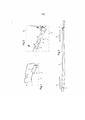
[00013] Um exemplo preferido da invenção é dado a título de uma modalidade não limitativa, conforme apresentado nos desenhos em anexo. É mostrado, na Figura 1 - uma vista em perspectiva de uma vedação de uma carenagem entre a asa e uma fuselagem de um avião de acordo com a invenção; Figura 2 - uma seção ampliada de uma vista em perspectiva da figura 1; Figura 3 - uma vista em seção transversal entre uma asa e uma fuselagem de uma aeronave; Figura 4 - uma vista em perspectiva de uma vedação de acordo com a invenção; Figura 5 - uma outra vista em perspectiva de uma vedação de acordo com a invenção, e Figura 6 - uma outra vista em perspectiva de uma vedação montada entre uma asa e uma fuselagem de um avião, de acordo com a invenção;[00013] A preferred example of the invention is given by way of a non-limiting modality, as shown in the attached drawings. Figure 1 shows a perspective view of a fairing seal between the wing and an airplane fuselage according to the invention; Figure 2 - an enlarged section of a perspective view of Figure 1; Figure 3 - a cross-sectional view between a wing and an aircraft fuselage; Figure 4 - a perspective view of a seal according to the invention; Figure 5 - another perspective view of a fence according to the invention, and Figure 6 - another perspective view of a fence assembled between an airplane wing and fuselage, according to the invention;
[00014] A figura 1: uma vedação contra o fluxo de ar transversal é montada em uma aba inferior de uma carenagem 2 entre uma asa 3 e uma fuselagem 4 de um avião (não mostrado).[00014] Figure 1: a seal against the transverse air flow is mounted on a lower flange of a
[00015] A figura 2: características correspondentes têm as referencias da figura 1. A vedação 1 é provida de duas gaxetas 5, 6, tal como lábios de borracha macia, entre as respectivas extremidades dos lados interno e externo 7, 8 da vedação 1 contra o fluxo de ar longitudinal ao longo da carenagem 2 entre a asa 3 e a fuselagem 4 do avião.[00015] Figure 2: corresponding characteristics have the references of figure 1.
[00016] A figura 3: características correspondentes têm as referencias da figura 1 e 2. O lado externo 8 da vedação 1 é montado na asa 3. A opção de fluxo de ar longitudinal através da vedação 1 e da asa 3 é indicado pela seta 9.[00016] Figure 3: corresponding characteristics have the references of figure 1 and 2. The outer side 8 of the
[00017] As figuras 4, 5: características correspondentes têm as referências das figuras 1, 2 e 3. A vedação 1 é equipada de duas gaxetas 5, 6, inteiriça com os lados opostos interno e externo 7, 8 da vedação 1. Em uma posição relaxada da vedação 1 (figura 4), as duas gaxetas 5, 6 têm uma forma convexa, enquanto as duas gaxetas 5, 6 têm uma forma plana menos convexa, mais plana, com os lados opostos 7, 8 sendo mais abertos se a vedação 1 estiver em uma posição montada.[00017] Figures 4, 5: corresponding characteristics have the references of figures 1, 2 and 3.
[00018] A figura 6: características correspondentes têm as refere- ncias da figura 1-5. Se a vedação 1 for pressionada contra uma estrutura como um painel da asa 3, os lados opostos 7, 8 da vedação 1 são curvados abertos, esticando, assim, as duas gaxetas 5, 6 da forma mais convexa para a forma menos convexa, mas plana, entre os lados interno e externo 7, 8, inclinando, assim, as respectivas extremidades livres 10 das gaxetas 5, 6 contra o painel da asa 3 para obstruir o fluxo de ar longitudinal.[00018] Figure 6: corresponding characteristics have the references of figure 1-5. If the
Claims (3)
Applications Claiming Priority (2)
| Application Number | Priority Date | Filing Date | Title |
|---|---|---|---|
| EP09400061A EP2338787B1 (en) | 2009-12-21 | 2009-12-21 | Sealing of airflow between a wing and a fuselage |
| EP09400061.9 | 2009-12-21 |
Publications (2)
| Publication Number | Publication Date |
|---|---|
| BRPI1004106A2 BRPI1004106A2 (en) | 2013-02-26 |
| BRPI1004106B1 true BRPI1004106B1 (en) | 2020-07-07 |
Family
ID=42166449
Family Applications (1)
| Application Number | Title | Priority Date | Filing Date |
|---|---|---|---|
| BRPI1004106-0A BRPI1004106B1 (en) | 2009-12-21 | 2010-10-27 | airflow seal between a wing and a fuselage |
Country Status (4)
| Country | Link |
|---|---|
| US (1) | US8485472B2 (en) |
| EP (1) | EP2338787B1 (en) |
| AT (1) | ATE537059T1 (en) |
| BR (1) | BRPI1004106B1 (en) |
Families Citing this family (5)
| Publication number | Priority date | Publication date | Assignee | Title |
|---|---|---|---|---|
| US20150048212A1 (en) * | 2013-08-19 | 2015-02-19 | The Boeing Company | Unsteady aerodynamics mitigation for multi-body aerospace apparatus |
| CN105083527B (en) * | 2014-05-07 | 2017-04-19 | 哈尔滨飞机工业集团有限责任公司 | Helicopter dedicated damping device |
| US9725155B2 (en) | 2015-12-30 | 2017-08-08 | General Electric Company | Method and system for open rotor engine fuselage protection |
| US20190225318A1 (en) * | 2018-01-25 | 2019-07-25 | General Electric Company | Aircraft systems and methods |
| EP3816040B1 (en) * | 2019-10-29 | 2024-01-10 | Airbus Operations, S.L.U. | Seal for an aircraft |
Family Cites Families (10)
| Publication number | Priority date | Publication date | Assignee | Title |
|---|---|---|---|---|
| DE694021C (en) * | 1939-07-02 | 1940-07-24 | Messerschmitt A G | Gap lining for aircraft |
| FR1523404A (en) * | 1967-03-22 | 1968-05-03 | Sud Aviation | Improvement in the connections between the fuselage and the wing of an aerodyne |
| FR2789144A1 (en) * | 1999-02-03 | 2000-08-04 | Joint Francais | Aircraft panel seal has internal reinforcing member with projections for joining to panel by fixings |
| FR2827028B1 (en) * | 2001-07-06 | 2003-09-26 | Airbus France | AIRCRAFT WITH VENTRAL CARENAGE AND JOINT FOR SUCH AN AIRCRAFT |
| EP1300335B1 (en) * | 2001-10-05 | 2005-03-02 | Airbus France | Aircraft with belly fairing seal |
| FR2869872B1 (en) | 2004-05-04 | 2007-07-20 | Airbus France Sas | A TRANSITIONAL SHING BETWEEN A MEANS FOR FIXING A WING ON A FUSELAGE OF AN AIRCRAFT AND SAID WING, AND AN AIRCRAFT HAVING SUCH A SHIM. |
| FR2892999B1 (en) * | 2005-11-08 | 2008-02-01 | Airbus France Sas | AIRCRAFT COMPRISING A CENTRAL CARRIAGE PRESSURE ADJUSTER VESSEL BY LOCAL GEOMETRIC DEFORMATIONS |
| FR2936489B1 (en) * | 2008-09-30 | 2012-07-20 | Airbus France | AIRCRAFT CENTRAL TRONCON WITH WORKING VENTRAL CARENAGE |
| WO2010052446A1 (en) * | 2008-11-05 | 2010-05-14 | Airbus Uk Limited | Aircraft fairing |
| ES2386136B1 (en) * | 2009-03-30 | 2013-07-25 | Airbus Operations, S.L. | STRUCTURE FOR THE COUPLING OF THE FLAVOR OF AN AIRCRAFT |
-
2009
- 2009-12-21 EP EP09400061A patent/EP2338787B1/en not_active Not-in-force
- 2009-12-21 AT AT09400061T patent/ATE537059T1/en active
-
2010
- 2010-10-01 US US12/896,138 patent/US8485472B2/en active Active
- 2010-10-27 BR BRPI1004106-0A patent/BRPI1004106B1/en not_active IP Right Cessation
Also Published As
| Publication number | Publication date |
|---|---|
| BRPI1004106A2 (en) | 2013-02-26 |
| EP2338787A1 (en) | 2011-06-29 |
| EP2338787B1 (en) | 2011-12-14 |
| US8485472B2 (en) | 2013-07-16 |
| US20110147525A1 (en) | 2011-06-23 |
| ATE537059T1 (en) | 2011-12-15 |
Similar Documents
| Publication | Publication Date | Title |
|---|---|---|
| ES2237655T3 (en) | AIRCRAFT WITH VENTRAL CARENADO. | |
| BRPI1004106B1 (en) | airflow seal between a wing and a fuselage | |
| ES2348259T3 (en) | JOINT ASSEMBLY FOR USE WITH FLAT SPOILERS AND OTHER AIRCRAFT CONTROL SURFACES. | |
| CN100443370C (en) | Covering device for a hinge of an aircraft | |
| ES2399173T3 (en) | Aircraft pressure bulkhead | |
| ES2782799T3 (en) | Airflow configuration for a wind turbine rotor blade | |
| BRPI0806561B1 (en) | PROTECTION SHIELD FOR AIRCRAFT WINDOW | |
| ES2234993T3 (en) | AIRCRAFT WITH VENTRAL CARENADO BOARD. | |
| US7850119B2 (en) | Sealing system for the gap existing between the fuselage and the elevator of the orientable horizontal stabiliser of an aircraft, extended with an aerodynamic fairing for sealing of the opening existing between the fuselage and the orientable horizontal stabiliser | |
| JP4311691B2 (en) | Wake stabilizer for helmet and helmet | |
| BR102015023893A2 (en) | seamless passenger door air bag in instrument panel | |
| BRPI0901597A2 (en) | input duct for an auxiliary electrical unit, and auxiliary electrical unit | |
| BRPI0808205B1 (en) | high lift device, wing, and noise reduction frame for high lift device | |
| RU2688082C2 (en) | Turbojet engine nacelle comprises a secondary loop nozzle with rotatable flaps | |
| US7422177B2 (en) | Sealing device for a flap track in a belly fairing of an aircraft for a flap-actuating shaft | |
| US20210214072A1 (en) | Vertical tail unit for flow control | |
| US10358204B2 (en) | Joint assembly and method connecting an aircraft belly fairing to the fuselage provided with a particularly positioned stringer | |
| WO2016189793A1 (en) | Flap and aircraft | |
| BR112014022235B1 (en) | LANDING GEAR FOR AIRCRAFT AND METHOD OF REDUCING THE NOISE CREATED BY AN LANDING GEAR FOR AIRCRAFT IN USE | |
| JP6336362B2 (en) | aircraft | |
| US1961584A (en) | Frame for access opening for use in aircraft construction | |
| CN109383765A (en) | Damping device for exposed undercarriage chamber | |
| JP2015229814A (en) | Shield and helmet | |
| BR102016027686A2 (en) | PANEL ASSEMBLY WITH NOISE ATTENUATION SYSTEM EQUIPPED WITH A GEOMETRIC PATTERN FOR ACOUSTIC IMPEDANCE BY AIR | |
| BR102017008228A2 (en) | DECOMPRESSION PANEL ASSEMBLY, METHOD FOR INSTALLING DECOMPRESSION PANEL ASSEMBLY ON AN AIRCRAFT, AND, AIRCRAFT. |
Legal Events
| Date | Code | Title | Description |
|---|---|---|---|
| B03A | Publication of a patent application or of a certificate of addition of invention [chapter 3.1 patent gazette] | ||
| B25D | Requested change of name of applicant approved |
Owner name: AIRBUS HELICOPTERS DEUTSCHLAND GMBH (DE) |
|
| B06F | Objections, documents and/or translations needed after an examination request according [chapter 6.6 patent gazette] | ||
| B06U | Preliminary requirement: requests with searches performed by other patent offices: procedure suspended [chapter 6.21 patent gazette] | ||
| B09A | Decision: intention to grant [chapter 9.1 patent gazette] | ||
| B16A | Patent or certificate of addition of invention granted [chapter 16.1 patent gazette] |
Free format text: PRAZO DE VALIDADE: 20 (VINTE) ANOS CONTADOS A PARTIR DE 27/10/2010, OBSERVADAS AS CONDICOES LEGAIS. |
|
| B21F | Lapse acc. art. 78, item iv - on non-payment of the annual fees in time |
Free format text: REFERENTE A 13A ANUIDADE. |
|
| B24J | Lapse because of non-payment of annual fees (definitively: art 78 iv lpi, resolution 113/2013 art. 12) |
Free format text: EM VIRTUDE DA EXTINCAO PUBLICADA NA RPI 2746 DE 22-08-2023 E CONSIDERANDO AUSENCIA DE MANIFESTACAO DENTRO DOS PRAZOS LEGAIS, INFORMO QUE CABE SER MANTIDA A EXTINCAO DA PATENTE E SEUS CERTIFICADOS, CONFORME O DISPOSTO NO ARTIGO 12, DA RESOLUCAO 113/2013. |