BRPI1001963B1 - ELECTRONIC FLIGHT CASE COMPUTER TO PROVIDE FLIGHT DATA TO AIRCRAFT PILOTS - Google Patents
ELECTRONIC FLIGHT CASE COMPUTER TO PROVIDE FLIGHT DATA TO AIRCRAFT PILOTS Download PDFInfo
- Publication number
- BRPI1001963B1 BRPI1001963B1 BRPI1001963-4A BRPI1001963A BRPI1001963B1 BR PI1001963 B1 BRPI1001963 B1 BR PI1001963B1 BR PI1001963 A BRPI1001963 A BR PI1001963A BR PI1001963 B1 BRPI1001963 B1 BR PI1001963B1
- Authority
- BR
- Brazil
- Prior art keywords
- compartment
- shelter
- fan
- electronic components
- electronic
- Prior art date
Links
Images


Classifications
-
- G—PHYSICS
- G06—COMPUTING; CALCULATING OR COUNTING
- G06F—ELECTRIC DIGITAL DATA PROCESSING
- G06F1/00—Details not covered by groups G06F3/00 - G06F13/00 and G06F21/00
- G06F1/16—Constructional details or arrangements
- G06F1/20—Cooling means
- G06F1/203—Cooling means for portable computers, e.g. for laptops
-
- G—PHYSICS
- G06—COMPUTING; CALCULATING OR COUNTING
- G06F—ELECTRIC DIGITAL DATA PROCESSING
- G06F1/00—Details not covered by groups G06F3/00 - G06F13/00 and G06F21/00
- G06F1/16—Constructional details or arrangements
- G06F1/1613—Constructional details or arrangements for portable computers
- G06F1/1633—Constructional details or arrangements of portable computers not specific to the type of enclosures covered by groups G06F1/1615 - G06F1/1626
- G06F1/1656—Details related to functional adaptations of the enclosure, e.g. to provide protection against EMI, shock, water, or to host detachable peripherals like a mouse or removable expansions units like PCMCIA cards, or to provide access to internal components for maintenance or to removable storage supports like CDs or DVDs, or to mechanically mount accessories
- G06F1/1658—Details related to functional adaptations of the enclosure, e.g. to provide protection against EMI, shock, water, or to host detachable peripherals like a mouse or removable expansions units like PCMCIA cards, or to provide access to internal components for maintenance or to removable storage supports like CDs or DVDs, or to mechanically mount accessories related to the mounting of internal components, e.g. disc drive or any other functional module
-
- B—PERFORMING OPERATIONS; TRANSPORTING
- B64—AIRCRAFT; AVIATION; COSMONAUTICS
- B64D—EQUIPMENT FOR FITTING IN OR TO AIRCRAFT; FLIGHT SUITS; PARACHUTES; ARRANGEMENTS OR MOUNTING OF POWER PLANTS OR PROPULSION TRANSMISSIONS IN AIRCRAFT
- B64D45/00—Aircraft indicators or protectors not otherwise provided for
- B64D2045/0075—Adaptations for use of electronic flight bags in aircraft; Supports therefor in the cockpit
Abstract
computador de saco de vôo eletrônico papa fornecer dados de vôo papa pilotos de aeronaves e módulo de ventilador para um computador de saco de vôo eletrônico papa fornecer dados de vôo a pilotos de aeronaves. computador de saco de vôo eletrônico (efb) que inclui um abrigo que define primeiro e segundo compartimentos que são isolados de forma fluida e em comunicação térmica entre si. o primeiro compartimento contém componentes eletrônicos conectados a uma interface de usuário sobre uma parte externa do abrigo para fornecer funções de computação relativas a vôo interativas a um usuário. o segundo compartimento contém um componente de resfriamento por convecção forçada em comunicação térmica com os componentes eletrônicos. o componente de resfriamento por convecção forçada dirige um fluxo de fluido de resfriamento no segundo compartimento para conduzir o calor produzido pelos componentes eletrônicos para fora do abrigo, de tal forma que o fluido de resfriamento no segundo compartimento permaneça isolado de forma fluida dos componentes eletrônicos no primeiro compartimento do abrigo.pope electronic flight bag computer provide pope flight data to aircraft pilots and fan module for a pope electronic flight bag computer provide flight data to aircraft pilots. electronic flight bag computer (efb) that includes a shelter that defines first and second compartments that are fluidly isolated and in thermal communication with each other. the first compartment contains electronic components connected to a user interface on the outside of the shelter to provide interactive flight-related computing functions to a user. the second compartment contains a forced convection cooling component in thermal communication with the electronic components. the forced convection cooling component directs a flow of cooling fluid in the second compartment to drive the heat produced by the electronic components out of the shelter, such that the cooling fluid in the second compartment remains fluidly isolated from the electronic components in the first compartment of the shelter.
Description
[001] A presente invenção refere-se ao resfriamento de componentes eletrônicos e, mais especificamente, a sistemas de refrigeração para dispositivos eletrônicos a bordo de aeronaves.[001] The present invention relates to the cooling of electronic components and, more specifically, to cooling systems for electronic devices on board aircraft.
[002] Malas de voo eletrônicos (EFBs) são computadores utilizados por tripulações de aeronaves como substituto para as malas de voo tradicionais que contêm gráficos e dados de voo antigamente conduzidos pelos pilotos na aeronave. Um EFB fornece mapas eletrônicos, informações meteorológicas e outras informações para uso pela tripulação de voo em aeronaves modernas durante o voo. Um EFB tipico é integrado à cabine de comando e tipicamente não é removido da cabine exceto para manutenção ou substituição.[002] Electronic flight bags (EFBs) are computers used by aircraft crews as a substitute for traditional flight bags that contain graphics and flight data formerly conducted by pilots on the aircraft. An EFB provides electronic maps, weather information and other information for use by the flight crew on modern aircraft during the flight. A typical EFB is integrated into the cockpit and is typically not removed from the cockpit except for maintenance or replacement.
[003] O controle da temperatura para componentes eletrônicos e, particularmente, processadores computadorizados, é uma questão para dispositivos de computação tais como EFBs. Diversas medidas vêm sendo tomadas para manter temperaturas seguras de componentes eletrônicos em computadores, que variam de uma aplicação para outra. Os dispositivos eletrônicos utilizados em aplicações aeroespaciais devem possuir um alto grau de confiabilidade em comparação com o equipamento eletrônico não aeroespacial em geral. Como os motores tais como os utilizados em ventiladores de resfriamento tipicos possuem uma confiabilidade relativamente baixa em comparação com os dispositivos eletrônicos tipicamente utilizados em aplicações aeroespaciais, ventiladores frequentemente não são utilizados em equipamento EFB convencional porque é necessário substituir um ventilador de resfriamento tipico antes do que é considerado um tempo razoável para a falha. Além disso, em EFBs convencionais, o uso de um ventilador de resfriamento para soprar ar sobre componentes eletrônicos pode gerar falha precoce de um EFB caso contaminantes comuns como poeira, umidade ou sal sejam capturados no fluxo de ar. Além disso, os próprios ventiladores podem também gerar falha precoce de EFBs. Os ventiladores podem falhar devido a vibrações e temperaturas extremas, o que reduz o Tempo Médio de Falha de um EFE. Em vez de ventiladores de resfriamento, muitos EFBs convencionais empregam dispositivos de resfriamento passivos elaborados que tipicamente aumentam o custo e o volume do projeto. Estes meios tradicionais de EFBs de resfriamento podem também resultar em comprometimento da capacidade ou redução dos limites ambientais de operação.[003] Temperature control for electronic components, and particularly computerized processors, is an issue for computing devices such as EFBs. Several measures have been taken to maintain safe temperatures for electronic components in computers, which vary from one application to another. Electronic devices used in aerospace applications must have a high degree of reliability compared to non-aerospace electronic equipment in general. As motors such as those used in typical cooling fans have relatively low reliability compared to electronic devices typically used in aerospace applications, fans are often not used in conventional EFB equipment because it is necessary to replace a typical cooling fan sooner than it is considered a reasonable time for failure. In addition, in conventional EFBs, the use of a cooling fan to blow air over electronic components can cause an EFB to fail early if common contaminants such as dust, moisture or salt are captured in the air flow. In addition, the fans themselves can also generate early failure of EFBs. Fans can fail due to extreme temperatures and vibrations, which reduces the average failure time of an EFE. Instead of cooling fans, many conventional EFBs employ elaborate passive cooling devices that typically increase the cost and volume of the project. These traditional means of cooling EFBs can also result in impaired capacity or reduced environmental operating limits.
[004] Os sistemas e métodos convencionais vêm geralmente sendo considerados satisfatórios para os seus propósitos pretendidos. Ainda permanece, entretanto, uma necessidade continua na técnica de um EFB com um fator de forma menor com dissipação de potência aceitável. Permanece ainda a necessidade na técnica de um EFB que seja de fácil elaboração e uso. A presente invenção fornece uma solução para estes problemas.[004] Conventional systems and methods have generally been found to be satisfactory for their intended purposes. There remains, however, a continuing need in the technique of an EFB with a smaller form factor with acceptable power dissipation. There is still a need in the technique for an EFB that is easy to prepare and use. The present invention provides a solution to these problems.
[005] A presente invenção refere-se a um novo computador de mala de voo eletrônico útil para fornecer de dados de voo para pilotos de aeronaves. O computador de mala de voo eletrônico inclui UNI abrigo que define primeiro e segundo compartimentos que são isolados de forma fluida e encontra-se em comunicação térmica entre si. O primeiro compartimento contém componentes eletrônicos conectados a uma interface de usuário sobre uma parte externa do abrigo para fornecer funções de computação relativa de voo interativo para um usuário. 0 segundo compartimento contém um componente de resfriamento por convecção forçada em comunicação térmica com os componentes eletrônicos. 0 componente de resfriamento por convecção forçada dirige um fluxo de fluido de resfriamento para o segundo compartimento para conduzir calor produzido pelos componentes eletrônicos para fora do abrigo, de tal forma que o fluido de resfriamento no segundo compartimento permaneça isolado de forma fluida dos componentes eletrônicos no primeiro compartimento do abrigo.[005] The present invention relates to a new electronic flight bag computer useful for providing flight data to aircraft pilots. The electronic flight bag computer includes UNI shelter that defines first and second compartments that are fluidly isolated and are in thermal communication with each other. The first compartment contains electronic components connected to a user interface on an outside part of the shelter to provide interactive flight relative computing functions for a user. The second compartment contains a forced convection cooling component in thermal communication with the electronic components. The forced convection cooling component directs a flow of cooling fluid into the second compartment to conduct heat produced by the electronic components out of the shelter, such that the cooling fluid in the second compartment remains fluidly isolated from the electronic components in the first compartment of the shelter.
[006] Em certas realizações, o componente de resfriamento por convecção forçada inclui um ventilador configurado para dirigir ar de resfriamento do lado externo do abrigo para o segundo compartimento e para dirigir ar aquecido do segundo compartimento para o lado externo do abrigo. O ventilador pode ser conectado eletricamente aos componentes eletrônicos no primeiro compartimento do abrigo por meio de um revestimento de fio para fornecer energia para o ventilador. O primeiro e segundo compartimento do abrigo pode encontrar-se em comunicação térmica por meio de um componente de trajeto condutor térmico configurado para conduzir calor do primeiro compartimento para o segundo compartimento.[006] In certain embodiments, the forced convection cooling component includes a fan configured to direct cooling air from the outside of the shelter to the second compartment and to direct heated air from the second compartment to the outside of the shelter. The fan can be electrically connected to the electronic components in the first compartment of the shelter through a wire jacket to supply power to the fan. The first and second compartment of the shelter can be in thermal communication by means of a thermally conductive path component configured to conduct heat from the first compartment to the second compartment.
[007] Também se contempla que, em certas realizações, os componentes eletrônicos incluem um processador no primeiro compartimento do abrigo com um receptor de calor. O segundo compartimento do abrigo inclui um trocador de calor espaçado do processador. Um componente de trajeto condutor térmico conecta termicamente o receptor de calor no primeiro compartimento ao trocador de calor do segundo compartimento.[007] It is also contemplated that, in certain embodiments, the electronic components include a processor in the first compartment of the shelter with a heat receiver. The second compartment of the shelter includes a heat exchanger spaced from the processor. A thermally conductive path component thermally connects the heat receiver in the first compartment to the heat exchanger in the second compartment.
[008] Segundo certas realizações, o segundo compartimento inclui um trocador de calor em comunicação térmica com os componentes eletrônicos do primeiro compartimento. O componente de resfriamento por convecção forçada inclui um ventilador no segundo compartimento do abrigo. 0 abrigo inclui uma porta de entrada próxima ao ventilador e uma porta de exaustão próxima ao trocador de calor. A porta de entrada e a porta de exaustão podem ser definidas em pelo menos um painel de acesso removivel do abrigo. 0 painel de acesso removivel pode ser configurado para remoção e substituição do abrigo para fornecer acesso ao segundo compartimento do abrigo, mantendo ao mesmo tempo o primeiro compartimento do abrigo isolado de forma fluida do segundo compartimento do abrigo.[008] According to certain embodiments, the second compartment includes a heat exchanger in thermal communication with the electronic components of the first compartment. The forced convection cooling component includes a fan in the second compartment of the shelter. The shelter includes an entrance door next to the fan and an exhaust door next to the heat exchanger. The entrance door and the exhaust door can be defined in at least one removable access panel of the shelter. The removable access panel can be configured for removal and replacement of the shelter to provide access to the second compartment of the shelter, while maintaining the first compartment of the shelter fluidly isolated from the second compartment of the shelter.
[009] A presente invenção também inclui um computador de mala de voo eletrônico para fornecer dados de voo para pilotos de aeronaves que possuem um módulo de ventilador removivel. Um abrigo define primeiro e segundo compartimentos internos. Os primeiro e segundo compartimentos internos são isolados por fluido e encontra-se em comunicação térmica entre si. O primeiro compartimento contém componentes eletrônicos conectados a uma interface de usuário sobre uma parte externa do abrigo para fornecer funções de computação relativas a voos interativos para um usuário. O módulo de ventilador removivel encontra-se no segundo compartimento do abrigo. O módulo de ventilador e configurado e adaptado para dirigir um fluxo de fluido de resfriamento para o segundo compartimento para conduzir calor produzido pelos componentes eletrônicos para fora do abrigo, de tal forma que o fluido de resfriamento permaneça isolado do fluido do primeiro compartimento do abrigo. O módulo de ventilador é configurado e adaptado para remoção e substituição do segundo compartimento do abrigo, mantendo ao mesmo tempo o isolamento fluido entre os primeiro e segundo compartimentos do abrigo.[009] The present invention also includes an electronic flight bag computer to provide flight data for aircraft pilots who have a removable fan module. A shelter defines first and second internal compartments. The first and second internal compartments are isolated by fluid and are in thermal communication with each other. The first compartment contains electronic components connected to a user interface on the outside of the shelter to provide computing functions related to interactive flights for a user. The removable fan module is located in the second compartment of the shelter. The fan module is configured and adapted to direct a flow of cooling fluid to the second compartment to conduct heat produced by the electronic components outside the shelter, such that the cooling fluid remains isolated from the fluid in the first compartment of the shelter. The fan module is configured and adapted to remove and replace the second compartment of the shelter, while maintaining fluid isolation between the first and second compartments of the shelter.
[0010] Em certas realizações, o módulo de ventilador inclui um ventilador que é conectado eletricamente aos componentes eletrônicos no primeiro compartimento do abrigo por uma conexão de doca para fornecer energia para o ventilador. O módulo de ventilador pode ser configurado e adaptado para remoção e instalação a partir do segundo compartimento do abrigo com o abrigo a bordo de uma aeronave. Também se contempla que o módulo de ventilador e os componentes eletrônicos podem ser configurados e adaptados para continuar a operação dos componentes eletrônicos ao longo de toda a remoção do módulo de ventilador do segundo compartimento. 0 módulo de ventilador pode ser conectado ao abrigo por mero de deslizamento, enchimento, grampeamento, fitas, colagem e/ou fixação.[0010] In certain embodiments, the fan module includes a fan that is electrically connected to the electronic components in the first compartment of the shelter by a dock connection to supply power to the fan. The fan module can be configured and adapted for removal and installation from the second compartment of the shelter with the shelter on board an aircraft. It is also contemplated that the fan module and the electronic components can be configured and adapted to continue the operation of the electronic components throughout the removal of the fan module from the second compartment. The fan module can be connected to the shelter by simply sliding, filling, stapling, tapes, gluing and / or fixing.
[0011] A presente invenção também inclui um módulo de ventilador para um computador de mala de voo eletrônico para fornecer dados de voo para pilotos de aeronaves. O módulo de ventilador inclui um abrigo de ventilador configurado e adaptado para instalação removivel em um abrigo de computador de mala de voo eletrônico. Um ventilador no abrigo de ventilador é configurado para girar em volta de um eixo para dirigir um fluxo de fluido de resfriamento para fornecer resfriamento por convecção forçada para componentes eletrônicos no abrigo de computador de mala de voo eletrônico. Uma entrada é definida no abrigo de ventilador e é configurada para acomodar a passagem de fluido de resfriamento do lado externo do abrigo de ventilador para o ventilador no interior do abrigo de ventilador ao longo de[0011] The present invention also includes a fan module for an electronic flight case computer to provide flight data to aircraft pilots. The fan module includes a fan housing configured and adapted for removable installation in an electronic flight bag computer cover. A fan in the fan housing is configured to rotate around an axis to direct a flow of cooling fluid to provide forced convection cooling for electronic components in the electronic flight case computer housing. An inlet is defined in the fan housing and is configured to accommodate the passage of cooling fluid from the outside of the fan housing to the fan inside the fan housing along
[0012] uma direção substancialmente alinhada ao eixo do ventilador. Uma saida é definida na abertura de abrigo do ventilador em uma direção substancialmente perpendicular à entrada do abrigo do ventilador. A saida é configurada e adaptada para canalizar um fluxo de fluido de resfriamento do ventilador para resfriar componentes no interior do abrigo de computador de mala de voo eletrônico. Uma conexão elétrica é configurada e adaptada para acoplar eletricamente o ventilador a uma fonte de energia no abrigo de computador de mala de voo eletrônico para alimentar o ventilador. O abrigo de ventilador e a conexão elétrica são configurados e adaptados para instalação e remoção manual do abrigo de computador de mala de voo eletrônico com o restante do abrigo de computador de mala de voo eletrônico.[0012] a direction substantially aligned with the fan axis. An outlet is defined at the fan housing opening in a direction substantially perpendicular to the fan housing entrance. The outlet is configured and adapted to channel a flow of cooling fluid from the fan to cool components inside the electronic flight case computer housing. An electrical connection is configured and adapted to electrically couple the fan to a power source in the electronic flight case computer housing to power the fan. The fan housing and electrical connection are configured and adapted for manual installation and removal of the electronic flight bag computer cover with the rest of the electronic flight bag computer cover.
[0013] Estas e outras características dos sistemas e métodos conforme a presente invenção tornar-se-ão mais facilmente evidentes para os técnicos no assunto a partir da descrição detalhada a seguir das realizações preferidas tomada em conjunto com as figuras.[0013] These and other characteristics of the systems and methods according to the present invention will become more easily apparent to those skilled in the art from the detailed description below of the preferred embodiments taken in conjunction with the figures.
[0014] Para que os técnicos no assunto a que pertence a presente invenção compreendam facilmente como elaborar e utilizar os dispositivos e métodos conforme a presente invenção sem experimentação indevida, suas realizações preferidas serão descritas em detalhes abaixo com referência a certas figuras, nas quais:[0014] In order for those skilled in the subject to which the present invention belongs to easily understand how to design and use the devices and methods according to the present invention without undue experimentation, their preferred achievements will be described in detail below with reference to certain figures, in which:
[0015] - a Fig. 1 é uma vista em perspectiva de uma cabine de comando do estado da técnica, que exibe uma mala de voo eletrônico (EFB) para fornecer dados de voo para os pilotos;[0015] - Fig. 1 is a perspective view of a state-of-the-art control cabin, which displays an electronic flight case (EFB) to provide flight data for pilots;
[0016] - a Fig. 2 é uma Vista traseira de um EFB construído conforme a presente invenção, que exibe um painel removível que cobre um compartimento de resfriamento no abrigo de EFB;[0016] - Fig. 2 is a rear view of an EFB built in accordance with the present invention, which shows a removable panel that covers a cooling compartment in the EFB shelter;
[0017] - a Fig. 3 é uma Vista de corte parcial ampliada de uma parte do EFB da Fig. 2, que exibe o compartimento de resfriamento com o painel de acesso removido para revelar o módulo de ventilador e trocador de calor;[0017] - Fig. 3 is an enlarged partial section view of a part of the EFB of Fig. 2, which shows the cooling compartment with the access panel removed to reveal the fan and heat exchanger module;
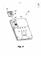
[0018] - a Fig. 4 é uma vista em perspectiva do EFB da Fig. 2, que exibe o módulo de ventilador removido;[0018] - Fig. 4 is a perspective view of the EFB of Fig. 2, which shows the removed fan module;
[0019] - a Fig. 5 é uma vista em perspectiva de uma outra realização de um EFB construído conforme a presente invenção que exibe a entrada de ar fresco das vizinhanças e a remoção de ar aquecido do interior do abrigo de EFB;[0019] - Fig. 5 is a perspective view of another embodiment of an EFB built in accordance with the present invention that shows the entry of fresh air from the neighborhoods and the removal of heated air from inside the EFB shelter;
[0020] - a Fig. 6 é uma vista em perspectiva parcial de todos os componentes do EFB da Fig. 5, que exibe os painéis de acesso removidos para revelar o módulo de ventilador e o trocador de calor;[0020] - Fig. 6 is a partial perspective view of all the components of the EFB of Fig. 5, which shows the access panels removed to reveal the fan module and the heat exchanger;
[0021] - a Fig. 7 é uma vista em perspectiva parcial de todos os componentes do EFB da Fig. 6, que exibe o módulo de ventilador e o trocador de calor removidos do abrigo de EFB; e[0021] - Fig. 7 is a partial perspective view of all the components of the EFB of Fig. 6, which shows the fan module and the heat exchanger removed from the EFB shelter; and
[0022] - a Fig. 8 é uma vista em perspectiva do EFB da Fig. 5, que exibe a cobertura traseira removida para exibir o receptor de calor, o trocador de calor e o módulo de ventilador junto com os componentes eletrônicos no interior do abrigo de EFB.[0022] - Fig. 8 is a perspective view of the EFB of Fig. 5, which shows the rear cover removed to display the heat receiver, the heat exchanger and the fan module together with the electronic components inside the EFB shelter.
[0023] Far-se-á agora referência às figuras, nas quais algarismos de referência identificam aspectos ou características estruturais similares da presente invenção. Para fins de explicação e ilustração, e não de limitação, uma[0023] Reference will now be made to the figures, in which reference figures identify similar structural aspects or characteristics of the present invention. For purposes of explanation and illustration, not limitation, a
[0024] vista parcial de um exemplo de realização de uma mala de voo eletrônico conforme a presente invenção é exibida na Fig. 2 e é designada, de forma geral, pelo algarismo de referência 100.[0024] partial view of an example of making an electronic flight bag according to the present invention is shown in Fig. 2 and is designated, in general, by the
[0025] Outras realizações de malas de voo eletrônicos conforme a presente invenção ou seus aspectos são fornecidos nas Figs. 3 a 8, como será, descrito. Os sistemas conforme a presente invenção pode ser utilizada para o resfriamento de componentes eletrônicos de mala de voo eletrônico fornecendo ao mesmo tempo um fator de forma favorável.[0025] Other embodiments of electronic flight bags according to the present invention or its aspects are provided in Figs. 3 to 8, as will be described. The systems according to the present invention can be used for the cooling of electronic components of the electronic flight case while providing a favorable form factor.
[0026] Conforme exibido na Fig. 1, um computador de mala de voo eletrônico (EFB) 10 e comumente utilizado para substituir os gráficos de papel, manuais e outras referências tradicionalmente conduzidas a bordo em malas de voo de pilotos. Um EFB é um computador com um visor para exibir mapas em movimento, padrões meteorológicos, dados técnicos e outras informações.[0026] As shown in Fig. 1, an electronic flight bag computer (EFB) 10 is commonly used to replace paper graphics, manuals and other references traditionally carried on board in pilots' flight bags. An EFB is a computer with a display to display moving maps, weather patterns, technical data and other information.
[0027] A Fig. 2 exibe um EFB 100 construido conforme a presente invenção. O EFB 100 inclui um abrigo 102 que define primeiro e segundo compartimentos que são isolados de forma fluida e encontra-se em comunicação térmica entre si. A Fig. 3 exibe uma vista ampliada do EFB 100 com uma parte do abrigo 102 removida. O primeiro compartimento 104 contém componentes eletrônicos conectados à interface de usuário sobre uma parte externa do abrigo 102 (não exibido na Fig. 2, mas vide a Fig. 1) para fornecer funções de computação relativas ao voo interativas para um usuário. O segundo compartimento 106 contém um componente de resfriamento por convecção forçada que inclui um módulo de ventilador 108 que se encontra em comunicação térmica com os componentes eletrônicos no primeiro compartimento 104. O fluido de resfriamento no segundo compartimento 106 permanece isolado de forma fluida dos componentes eletrônicos no primeiro compartimento 104 do abrigo 102.[0027] Fig. 2 shows an
[0028] O módulo de ventilador 108 inclui um ventilador configurado para dirigir o ar de resfriamento do lado externo do abrigo 102 para () segundo compartimento 106 e dirigir ar aquecido do segundo compartimento 106 para a área fora do abrigo 102, conforme indicado pelas setas na Fig. 3. O ventilador é conectado eletricamente aos componentes eletrônicos no primeiro componente 104 por meio de uma conexão de doca 110 para fornecer energia para dirigir o ventilador. O primeiro e segundo compartimentos 104 e 106 do abrigo 102 encontram-se em comunicação térmica entre si por meio de um componente de trajeto condutor térmico 112 configurado para conduzir calor do circuito eletrônico no primeiro compartimento 104 para o segundo compartimento 106, para remoção pelo ar de resfriamento.[0028] The
[0029] Os componentes eletrônicos em EFB 100 incluem um ou mais processadores no primeiro compartimento 104 que possui um receptor de calor. 0 segundo compartimento 106 inclui um trocador de calor 114 espaçado do processador no primeiro compartimento 104. O componente de trajeto condutor térmico 112 conecta termicamente o receptor de calor no primeiro compartimento 104 ao trocador de calor 114 no segundo compartimento 106. Desta forma, o trocador de calor 114 encontra-se em comunicação térmica com os componentes eletrônicos do primeiro compartimento 104. Os técnicos no assunto apreciarão que o componente de trajeto condutor 112 pode ser combinado como um único componente com um receptor de calor, como no receptor de calor 232 descrito abaixo, ou pode ser separado mas em comunicação térmica com o receptor de calor.[0029] The electronic components in
[0030] Novamente com referência à Fig. 2, o abrigo 102 inclui uma porta de entrada 116 próxima ao ventilador e uma porta de exaustão 118 próxima ao trocador de calor 114. A porta de entrada 116 e a porta de exaustão 118 são definidas em um painel de acesso removivel 120. O painel de acesso removivel 120 pode ser removido e substituído do abrigo 102 para fornecer acesso ao segundo compartimento 106, mantendo ao mesmo tempo o primeiro compartimento 104 isolado em fluido do segundo compartimento 106. Conforme indicado na Fig. 4, o módulo de ventilador 108 com conexão de doca 110 pode ser instalado e removido manualmente do abrigo 102 por meio de fixação através de uma abertura no lado do abrigo 102 com o restante do abrigo 102. Devido à configuração de doca lateral do módulo de ventilador 108, a remoção e a substituição do módulo de ventilador 108 podem ser realizadas com ou sem a remoção do painel de acesso 120.[0030] Again with reference to Fig. 2,
[0031] O mecanismo de doca 130 possibilita a liberação e desinstalação de um módulo de ventilador antigo 108 e a instalação de um novo módulo de ventilador 108 sem a necessidade de ferramentas. Desta forma, o módulo de ventilador 108 pode ser alterado sem a remoção de EFB 100 da aeronave e, dependendo da disposição da cabine de comando, isso pode até ser possivel sem a remoção do EFB 100 das suas disposições de montagem na cabine de comando. Caso o ventilador utilizado possua baixa voltagem inofensiva, a substituição do módulo de ventilador 108 pode ser realizada até mesmo sem desabilitar o equipamento. Mesmo se outras circunstâncias necessitarem que o EFB 100 seja removido da aeronave, a fácil remoção e instalação do módulo de ventilador 108 pode ainda economizar tempo durante a substituição que tem lugar fora da aeronave.[0031]
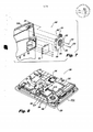
[0032] As Figs. 5 a 8 exibem um outro exemplo de realização de um EFB 200 construido conforme a presente invenção, que inclui um módulo de ventilador removivel 208. A Fig. 8 exibe EFB 200 com parte do abrigo 202 removida para exibir primeiro e segundo compartimentos 204 e 206, respectivamente, definidos no interior do abrigo 202 conforme descrito acima com relação ao EFB 100. Os primeiro e segundo compartimentos internos 204 e 206 são isolados por fluido e encontra-se em comunicação térmica entre si. O módulo de ventilador removivel 208 encontra-se no segundo compartimento 206 do abrigo 202, conforme exibido na Fig. 6. O módulo de ventilador 208 dirige um fluxo de fluido de resfriamento, tal como ar ambiente, para o segundo compartimento 206 e conduz calor produzido pelos componentes eletrônicos para fora do abrigo 202, conforme indicado pelas setas grandes da Fig. 5. O fluido de resfriamento permanece isolado do fluido do primeiro compartimento 204 e componentes eletrônicos no seu interior. O módulo ventilador 208 pode ser removido e substituído do segundo compartimento 206 do abrigo 202, mantendo ao mesmo tempo o isolamento fluido entre os primeiro e segundo compartimentos 204 e 206.[0032] Figs. 5 to 8 show another example of making an
[0033] O módulo de ventilador 208 é conectado eletricamente aos componentes eletrônicos no primeiro compartimento 204 por meio de um fio encapado 210 para fornecer energia para o ventilador 224. A Fig. 7 exibe o módulo de ventilador 208 removido do abrigo 202 com as duas partes de fio encapado 210 desconectadas entre si. O módulo de ventilador 208 pode ser removido do segundo compartimento 206 e nele instalado com EFB 200 a bordo de uma aeronave. Também se contempla que o módulo de ventilador 208 pode ser substituído a bordo de uma aeronave enquanto os componentes eletrônicos de EFB 200 continuam a operar, se necessário, conforme descrito acima. Conforme indicado na Fig. 7, o módulo de ventilador 208 é mantido no lugar por fixadores[0033] The
[0034] 222 de um tipo que pode ser fixado e liberado com uma ferramenta simples. Os técnicos no assunto apreciarão facilmente que um módulo de ventilador pode ser conectado mecanicamente a um abrigo de EFB por meio de deslizamento, enchimento, grampeamento, fitas, colagem ou qualquer outro meio apropriado sem abandonar o espirito e o escopo da presente invenção.[0034] 222 of a type that can be fixed and released with a simple tool. Those skilled in the art will easily appreciate that a fan module can be mechanically connected to an EFB shelter by sliding, filling, stapling, taping, gluing or any other appropriate means without abandoning the spirit and scope of the present invention.
[0035] O módulo de ventilador 208 inclui um abrigo de ventilador 209 configurado e adaptado para ser fixado ou instalado de forma removível no abrigo 202, conforme descrito acima. O ventilador 224 no interior do abrigo de ventilador 208 gira em volta do seu eixo (conforme indicado pela seta circular na Fig. 3, por exemplo) , para dirigir um fluxo de fluido de resfriamento para fornecer resfriamento por convecção forçada para componentes de EFB geradores de calor. Uma entrada 226 é definida no abrigo de ventilador 209 e é configurada para acomodar a passagem de fluido de resfriamento, tal como ar ambiente, para fora do abrigo 202 para o ventilador 224 ao longo de uma direção substancialmente alinhada com o eixo de rotação do ventilador 224. Uma saida 228 é definida no abrigo de ventilador 209 que se abre em uma direção substancialmente perpendicular à entrada 226 do abrigo de ventilador 209. A saida 228 canaliza um fluxo de fluido de resfriamento do ventilador 224 através do trocador de calor 214 para resfriar componentes no interior do abrigo 202.[0035]
[0036] Conforme exibido nas Figs. 5 e 6, o EFB 200 possui dois painéis de acesso 220 e 221. A porta de entrada 216 é definida no painel de acesso 220 e é posicionada ao lado do módulo de ventilador 208 quando fechada. A porta de exaustão 218 é definida no painel de acesso 221 e é posicionada ao lado do trocador de calor 214 quando fechada. O painel de acesso 220 pode ser aberto para ter acesso ao módulo de ventilador 208 ou substitui-lo. O painel de acesso 221 pode ser aberto para ter acesso ao trocador de calor 214, por exemplo, para limpar pô e/ou outro fragmento de membros de barbatanas 234 do trocador de calor 214.[0036] As shown in Figs. 5 and 6, the
[0037] Com referência agora à Fig. 8, o calor gerado pelos componentes eletrônicos, tais como um processador principal, é removido do EFB 200 da forma a seguir. O processador e/ou outros componentes geradores de calor de EFB 200 estão em boa proximidade e comunicação térmica com o receptor de calor 232. Os componentes geradores de calor não são exibidos, mas estão localizados apenas sob o receptor de calor 232 conforme observado na Fig. 8. O receptor de calor 232 recebe calor dos componentes geradores de calor e conduz o calor para o trocador de calor 214. O receptor de calor 232 é uma placa metálica que forma um trajeto condutor térmico dos componentes geradores de calor para o trocador de calor 214. Os técnicos no assunto reconhecerão que um cano de calor ou qualquer outro tipo apropriado de componente de trajeto condutor térmico pode ser utilizado sem abandonar o espirito e o escopo da presente invenção. O trocador de calor 214 encontra-se em comunicação térmica com o receptor de calor 232 para receber calor dele. 0 trocador de calor 214 conduz calor do receptor de calor 232 para membros de barbatanas 234. Os membros de barbatanas 234 aumentam a troca de calor com o fluido de resfriamento.[0037] With reference now to Fig. 8, the heat generated by the electronic components, such as a main processor, is removed from the
[0038] O fluxo de fluido de resfriamento, tal como ar, através de EFB 200 inclui a deposição de ar ambiente através da porta de entrada 216 no painel de acesso 220, conforme indicado na Fig. 5, e para o módulo de ventilador 208. O ar é dirigido do módulo de ventilador 208 através de membros de barbatana 234 do trocador de calor 214, onde o calor dos componentes geradores de calor é liberado de membros de barbatana 234 para o fluxo de ar de passagem por meio do processo de convecção forçada. O ar aquecido passa para fora do abrigo 202 através da porta de exaustão 218 no painel de acesso 221, conforme indicado na Fig. 5.[0038] The flow of cooling fluid, such as air, through
[0039] O uso de um ventilador de resfriamento para transferir calor do equipamento para o ambiente fornece uma razão entre dissipação de energia e fator de forma favorável para um EFB em comparação com EFBs convencionais que utilizam disposições de resfriamento passivo elaboradas. O uso de resfriamento por ar forçado fornece alta potência e dissipação de calor a baixo custo. Um módulo de ventilador de resfriamento pode ser substituído conforme a necessidade, tal como em decorrência de operação anormalmente alta ou contaminação com poeira ou em base de manutenção preventiva conforme apropriado.[0039] The use of a cooling fan to transfer heat from the equipment to the environment provides a ratio between energy dissipation and favorable factor for an EFB compared to conventional EFBs that use elaborate passive cooling arrangements. The use of forced air cooling provides high power and low-cost heat dissipation. A cooling fan module can be replaced as needed, such as due to abnormally high operation or contamination with dust or on a preventive maintenance basis as appropriate.
[0040] Os segundos compartimentos 106 e 206 de EFBs 100 e 200 encontram-se em contato térmico com os componentes geradores de calor nos primeiros compartimentos 104 e 204, respectivamente, para permitir a remoção do excesso de calor produzido durante a operação. O fluido de resfriamento, tal como ar, que flui através dos segundos compartimentos 106 e 206 e isolado, entretanto, dos componentes de geração de calor nos primeiros compartimentos 104 e 204, respectivamente. A manutenção do fluxo de ar de resfriamento isolado dos componentes eletrônicos protege os componentes eletrônicos contra a poeira, sal, umidade e outros contaminantes potencialmente perigosos que podem ser capturados no fluxo de ar. Este isolamento de fluido protege os componentes eletrônicos contra falhas prematuras causadas pela redução, perda de resistência de isolamento, contaminação das juntas de ligação e similares. Apenas componentes nos segundos compartimentos 106 e 206, tais como o módulo de ventilador e o trocador de calor, são expostos a contaminantes suspensos no ar e esses componentes expostos podem ser facilmente limpos ou substituídos conforme descrito acima.[0040] The
[0041] Os métodos e sistemas conforme a presente invenção, conforme descrito acima e exibido nas figuras, fornecem um EFB com propriedades superiores que incluem fator de forma pequena, proteção contra contaminantes suspensos no ar e eficiente remoção de calor. Além disso, a facilidade com que os módulos de ventilador podem ser alterados permite que EFBs construídos conforme a presente invenção seja mantida a bordo de uma aeronave durante a substituição do módulo de ventilador, o que pode aumentar o tempo entre a remoção do próprio EFB da aeronave para manutenção ou substituição.[0041] The methods and systems according to the present invention, as described above and shown in the figures, provide an EFB with superior properties that include small form factor, protection against airborne contaminants and efficient heat removal. In addition, the ease with which the fan modules can be changed allows EFBs built in accordance with the present invention to be kept on board an aircraft during the replacement of the fan module, which can increase the time between removing the EFB itself from the aircraft for maintenance or replacement.
[0042] Embora o aparelho e os métodos conforme a presente invenção tenham sido exibidos e descritos com referência a realizações preferidas, os técnicos no assunto apreciarão facilmente que alterações e/ou modificações podem ser realizadas sem abandonar o espirito e o escopo da presente invenção.[0042] Although the apparatus and methods according to the present invention have been displayed and described with reference to preferred embodiments, those skilled in the art will easily appreciate that changes and / or modifications can be made without abandoning the spirit and scope of the present invention.
Claims (14)
Applications Claiming Priority (2)
| Application Number | Priority Date | Filing Date | Title |
|---|---|---|---|
| US12/493,304 | 2009-06-29 | ||
| US12/493,304 US8120913B2 (en) | 2009-06-29 | 2009-06-29 | Methods and devices for forced air cooling of electronic flight bags |
Publications (2)
| Publication Number | Publication Date |
|---|---|
| BRPI1001963A2 BRPI1001963A2 (en) | 2012-03-06 |
| BRPI1001963B1 true BRPI1001963B1 (en) | 2020-09-29 |
Family
ID=42829947
Family Applications (1)
| Application Number | Title | Priority Date | Filing Date |
|---|---|---|---|
| BRPI1001963-4A BRPI1001963B1 (en) | 2009-06-29 | 2010-06-22 | ELECTRONIC FLIGHT CASE COMPUTER TO PROVIDE FLIGHT DATA TO AIRCRAFT PILOTS |
Country Status (4)
| Country | Link |
|---|---|
| US (2) | US8120913B2 (en) |
| EP (1) | EP2275901A3 (en) |
| BR (1) | BRPI1001963B1 (en) |
| CA (1) | CA2704869C (en) |
Families Citing this family (4)
| Publication number | Priority date | Publication date | Assignee | Title |
|---|---|---|---|---|
| KR102081928B1 (en) * | 2013-04-24 | 2020-02-26 | 엘지전자 주식회사 | Digital signage |
| US9167706B2 (en) | 2013-08-05 | 2015-10-20 | Steven J. Holmstrom | Electronic flight bag retention device |
| TWI536152B (en) * | 2015-05-26 | 2016-06-01 | 鴻海精密工業股份有限公司 | Dedusting structure and electronic system using same |
| CN108961470A (en) * | 2018-07-06 | 2018-12-07 | 广州番客信息科技有限公司 | It is a kind of can real-time transmission data automobile data recorder |
Family Cites Families (27)
| Publication number | Priority date | Publication date | Assignee | Title |
|---|---|---|---|---|
| US5689403A (en) * | 1994-12-27 | 1997-11-18 | Motorola, Inc. | Intercooled electronic device |
| US5831822A (en) * | 1997-01-07 | 1998-11-03 | Apple Computer, Inc. | Personal computer having quick-release cooling fan |
| US6003068A (en) * | 1997-02-14 | 1999-12-14 | Electronic Data Systems Corporation | Method and apparatus for portably providing shared removable resources to a plurality of computing devices |
| JP2001267771A (en) * | 2000-03-17 | 2001-09-28 | Hitachi Ltd | Electronic apparatus |
| JP3594900B2 (en) * | 2000-12-19 | 2004-12-02 | 株式会社日立製作所 | Display integrated computer |
| JP2002188876A (en) * | 2000-12-20 | 2002-07-05 | Hitachi Ltd | Liquid cooling system and personal computer provided with the system |
| US20020149905A1 (en) * | 2001-04-11 | 2002-10-17 | Jackson, Louiss R. | Flat hanging computer |
| JP3637304B2 (en) * | 2001-11-29 | 2005-04-13 | 株式会社東芝 | Small electronic equipment |
| US7312985B2 (en) * | 2002-03-08 | 2007-12-25 | Lg Electronics Inc. | Cooler of notebook personal computer and fabrication method thereof |
| TW588823U (en) * | 2002-05-13 | 2004-05-21 | Shuttle Inc | CPU heat dissipation apparatus having heat conduction pipe |
| US7269005B2 (en) * | 2003-11-21 | 2007-09-11 | Intel Corporation | Pumped loop cooling with remote heat exchanger and display cooling |
| US7068508B2 (en) * | 2003-12-08 | 2006-06-27 | Hewlett-Packard Development Company, L.P. | Docking station cooling system including liquid-filled hollow structure |
| US20050276018A1 (en) * | 2004-06-14 | 2005-12-15 | Moore Earl W | Thermal management system for a portable computing device |
| US7061761B2 (en) * | 2004-07-30 | 2006-06-13 | Hewlett-Packard Development Company, L.P. | System and method for cooling components in an electronic device |
| US7680250B1 (en) * | 2004-11-24 | 2010-03-16 | Interactive Quality Services | Interactive method and system of testing an automated call telephonic communication system |
| US7333330B2 (en) * | 2005-02-04 | 2008-02-19 | Technology Advanced Group, Inc. | Electronic component chassis with isolated power supply cooling |
| JP2006250132A (en) * | 2005-03-14 | 2006-09-21 | Nippon Densan Corp | Blower and its related technique |
| TWM281218U (en) * | 2005-05-17 | 2005-11-21 | Twinhead Int Corp | Waterproof and dust-proof structure for radiator of notebook computer |
| JP4167700B2 (en) * | 2006-05-31 | 2008-10-15 | 株式会社東芝 | Electronics |
| US7403384B2 (en) * | 2006-07-26 | 2008-07-22 | Dell Products L.P. | Thermal docking station for electronics |
| US7779894B2 (en) * | 2006-07-31 | 2010-08-24 | Fu Zhun Precision Industry (Shen Zhen) Co., Ltd. | Heat dissipation device |
| TWI306188B (en) * | 2006-08-01 | 2009-02-11 | Compal Electronics Inc | Waterproof thermal management module and portable electronic apparatus using the same |
| FR2907758B1 (en) * | 2006-10-26 | 2009-05-15 | Airbus France Sa | DEVICE FOR INTEGRATING A LAPTOP COMPUTER IN AN AIRCRAFT COCKPIT |
| US8515656B2 (en) * | 2007-11-02 | 2013-08-20 | Goodrich Corporation | Integrated aircraft cargo loading and monitoring system |
| US8022843B2 (en) * | 2008-03-31 | 2011-09-20 | The Boeing Company | Wireless aircraft sensor network |
| US20100084118A1 (en) * | 2008-08-21 | 2010-04-08 | Airbus Operations | Cooling system for aircraft electric or electronic devices |
| US7872864B2 (en) * | 2008-09-30 | 2011-01-18 | Intel Corporation | Dual chamber sealed portable computer |
-
2009
- 2009-06-29 US US12/493,304 patent/US8120913B2/en active Active
-
2010
- 2010-05-20 CA CA2704869A patent/CA2704869C/en active Active
- 2010-06-22 BR BRPI1001963-4A patent/BRPI1001963B1/en active IP Right Grant
- 2010-06-24 EP EP10006593.7A patent/EP2275901A3/en not_active Ceased
-
2012
- 2012-01-23 US US13/355,671 patent/US20120121385A1/en not_active Abandoned
Also Published As
| Publication number | Publication date |
|---|---|
| BRPI1001963A2 (en) | 2012-03-06 |
| CA2704869A1 (en) | 2010-12-29 |
| US20100328877A1 (en) | 2010-12-30 |
| US8120913B2 (en) | 2012-02-21 |
| EP2275901A3 (en) | 2015-09-16 |
| CA2704869C (en) | 2018-09-18 |
| EP2275901A2 (en) | 2011-01-19 |
| US20120121385A1 (en) | 2012-05-17 |
Similar Documents
| Publication | Publication Date | Title |
|---|---|---|
| US7307840B2 (en) | Cross-flow redundant air cooling method for high reliability electronics | |
| BRPI1001963B1 (en) | ELECTRONIC FLIGHT CASE COMPUTER TO PROVIDE FLIGHT DATA TO AIRCRAFT PILOTS | |
| US7150109B2 (en) | Dry-wet thermal management system | |
| KR101468874B1 (en) | The emergency protection apparatus of the server rack | |
| BR102014005628B1 (en) | ELECTRIC CABINET WITH IMPROVED HEAT DISSIPATION | |
| JPH08179008A (en) | Test head cooling device | |
| US9686886B2 (en) | Cooling mechanism of storage control apparatus | |
| CN207305238U (en) | The U-shaped independent ventiduct module heat dissipating system of ship rack-mount unit | |
| US11406038B2 (en) | Aircraft having computers distributed in the fuselage | |
| BR202017005465Y1 (en) | TUBE TOWER | |
| TW201338681A (en) | Server cabinnet | |
| JP2011085299A (en) | Air conditioner | |
| BR112017022641B1 (en) | AIRCRAFT AND AIRCRAFT SUPPLY SYSTEM | |
| US10721843B2 (en) | Cooling via a sleeve connector | |
| WO2024017327A1 (en) | Liquid cooling data center test device and liquid cooling data center test system | |
| RU94732U1 (en) | EXTERNAL COOLING OF AN INDUSTRIAL COMPUTER | |
| CN208047119U (en) | Electronic equipment | |
| US10681839B2 (en) | Cooling module and electronic unit comprising such a module | |
| JP2004295702A (en) | Server | |
| US20200029456A1 (en) | Electronic unit with reversible modules | |
| CN113655870A (en) | Extensible industrial computer system | |
| US11363744B2 (en) | Cooling system and cooling method | |
| TWM610358U (en) | Heat dissipation cabinet | |
| CN109757049A (en) | A kind of electronic information communication equipment | |
| CN106789114A (en) | Remote POE power supplying switches |
Legal Events
| Date | Code | Title | Description |
|---|---|---|---|
| B03A | Publication of a patent application or of a certificate of addition of invention [chapter 3.1 patent gazette] | ||
| B06F | Objections, documents and/or translations needed after an examination request according [chapter 6.6 patent gazette] | ||
| B06U | Preliminary requirement: requests with searches performed by other patent offices: procedure suspended [chapter 6.21 patent gazette] | ||
| B06A | Patent application procedure suspended [chapter 6.1 patent gazette] | ||
| B09A | Decision: intention to grant [chapter 9.1 patent gazette] | ||
| B16A | Patent or certificate of addition of invention granted [chapter 16.1 patent gazette] |
Free format text: PRAZO DE VALIDADE: 10 (DEZ) ANOS CONTADOS A PARTIR DE 29/09/2020, OBSERVADAS AS CONDICOES LEGAIS. |