BRPI0925220B1 - aircraft impact carrier aircraft structure and method for providing resistance to an aircraft - Google Patents
aircraft impact carrier aircraft structure and method for providing resistance to an aircraft Download PDFInfo
- Publication number
- BRPI0925220B1 BRPI0925220B1 BRPI0925220-7A BRPI0925220A BRPI0925220B1 BR PI0925220 B1 BRPI0925220 B1 BR PI0925220B1 BR PI0925220 A BRPI0925220 A BR PI0925220A BR PI0925220 B1 BRPI0925220 B1 BR PI0925220B1
- Authority
- BR
- Brazil
- Prior art keywords
- aircraft
- leading edge
- edge structure
- profile
- reinforcement
- Prior art date
Links
Images


Classifications
-
- B—PERFORMING OPERATIONS; TRANSPORTING
- B64—AIRCRAFT; AVIATION; COSMONAUTICS
- B64C—AEROPLANES; HELICOPTERS
- B64C3/00—Wings
- B64C3/28—Leading or trailing edges attached to primary structures, e.g. forming fixed slots
Landscapes
- Engineering & Computer Science (AREA)
- Mechanical Engineering (AREA)
- Aviation & Aerospace Engineering (AREA)
- Laminated Bodies (AREA)
- Compositions Of Macromolecular Compounds (AREA)
- Moulding By Coating Moulds (AREA)
- Elimination Of Static Electricity (AREA)
Abstract
ESTRUTURA DE BORDO DE ATAQUE DE AERONAVE RESISTENTE A IMPACTO, AERONAVE E MÉTODO PARA PROPORCIONAR RESISTÊNCIA A UMA AERONAVE Estruturas de empenagem de aeronaves têm resistência a impactos que atendem aos requisitos de certificação de aeronaves de transporte (por exemplo, Parte 25 da FAR e/ou outros requisitos para certificação internacional). As estruturas podem ser incorporadas especificamente nas estruturas de bordo de ataque que são aquelas preferencialmente na forma de componentes de uma única peça, moldados com materiais compostos reforçados com fibra (por ex., fibras de reforço, tais como fibras de vidro, fibras de aramida e/ou fibras de carbono incorporadas em uma matriz polimérica, como uma resina epóxi). As estruturas do bordo de ataque incluem, preferencialmente, um revestimento arqueado e reforço interno que se estende longitudinalmente, em forma geral de Y e que inclui um perfil planar e um par de braços de reforço planar divergentes. O perfil pode ser posicionado de forma coplanar com um plano que divide em dois a estrutura do bordo de ataque. Uma extremidade anterior do perfil pode, dessa forma, ser integralmente ligada na parte posterior de uma extremidade apical do revestimento, enquanto que uma extremidade posterior do perfil pode ser integralmente ligada a cada (...).IMPACT-RESISTANT AIRCRAFT ATTACK STRUCTURE, AIRCRAFT AND METHOD TO PROVIDE RESISTANCE TO AN AIRCRAFT Aircraft warping structures have impact resistance that meet transport aircraft certification requirements (for example, FAR Part 25 and / or other requirements for international certification). The structures can be incorporated specifically into the leading edge structures which are preferably those in the form of one-piece components, molded with fiber-reinforced composite materials (eg reinforcing fibers, such as glass fibers, aramid fibers and / or carbon fibers incorporated in a polymeric matrix, such as an epoxy resin). The leading edge structures preferably include an arcuate lining and internal reinforcement that extends longitudinally, in a general Y shape and that includes a planar profile and a pair of diverging planar reinforcement arms. The profile can be positioned coplanarly with a plane that divides the leading edge structure in two. An anterior end of the profile can therefore be integrally connected to the back of an apical end of the coating, while a posterior end of the profile can be integrally connected to each (...).
Description
As estruturas mencionadas se aplicam, de maneira geral, a aeronaves que possuem bordos de ataque resistentes a impactos.The structures mentioned apply, in general, to aircraft that have impact resistant attack edges.
Os requisitos para certificação de aeronavegabilidade para aeronaves de transporte sob a parte 25 das Normas da aviação federal dos EUA (FARs, 14 CFR) e outros requisitos para certificações internacionais equivalentes, normalmente requerem que as estruturas da aeronave suportem certos impactos em voo, como aves, sem que ocorra falha na fuselagem, permitindo que a aeronave continue o voo e pouse com segurança. Componentes como o bordo de ataque da empenagem (por exemplo, asas e estabilizadores horizontais e verticais) são componentes da fuselagem especialmente críticos. Assim sendo, a fim de atender aos requisitos de certificação de danos causados por fontes distintas da parte 25 das FAR (em anexo, como referência), a aeronave deve suportar o impacto de aves pesando até 4 libras (aprox. 1,8 kg) (FAR §25.571[e][l]) e 8 libras (aprox. 3,6 kg) (FAR §25.631) .Airworthiness certification requirements for transport aircraft under part 25 of the US Federal Aviation Standards (FARs, 14 CFR) and other requirements for equivalent international certifications, typically require that aircraft structures withstand certain impacts in flight, such as birds , without a fuselage failure, allowing the aircraft to continue its flight and land safely. Components such as the leading edge of the warp (for example, horizontal and vertical wings and stabilizers) are especially critical components of the fuselage. Therefore, in order to meet the certification requirements for damage caused by sources other than part 25 of the FAR (attached, as a reference), the aircraft must withstand the impact of birds weighing up to 4 pounds (approx. 1.8 kg) (FAR §25.571 [e] [l]) and 8 pounds (approx. 3.6 kg) (FAR §25.631).
A fim de garantir a integridade estrutural da estrutura da empenagem (conforme descrito nas FAR §25.631, por exemplo), um projeto de engenharia usual tem sido incluir um dispositivo adicional, coloquialmente chamado de "splitter plate" (placa fragmentadora), residindo fisicamente dentro do bordo de ataque, o qual é fixado firmemente à estrutura básica da empenagem (longarina). Em tal situação, o splitter plate é separado fisicamente do bordo de ataque, de maneira que, caso o bordo de ataque sofra o impacto de uma ave durante o voo, a placa divisora absorverá a energia do impacto fragmentando a ave e protegendo a estrutura básica da empenagem. Esta opção tradicional, de colocar um splitter plate associado operacionalmente com os bordos de ataque da empenagem, é eficaz, mas paga um preço substancial em termos de peso, uma vez que, de modo geral, o splitter plate é um componente estruturalmente rígido feito de metal (por exemplo, alumínio ou aço).In order to ensure the structural integrity of the bending structure (as described in FAR §25.631, for example), a common engineering project has been to include an additional device, colloquially called a "splitter plate", physically residing within the leading edge, which is firmly attached to the basic structure of the warp (stringer). In such a situation, the splitter plate is physically separated from the leading edge, so that if the leading edge is impacted by a bird during flight, the dividing plate will absorb the impact energy by fragmenting the bird and protecting the basic structure warping. This traditional option of placing a splitter plate operationally associated with the leading edges of the warping is effective, but it pays a substantial price in terms of weight, since, in general, the splitter plate is a structurally rigid component made of metal (for example, aluminum or steel).
Outras propostas foram feitas para oferecer resistência a impactos aos bordos de ataque das aeronaves. Por exemplo, uma proposta anterior foi objeto da publicação internacional WO2007/07138 (aqui incorporada, como referência) na qual se propõe um revestimento protetor arqueado, moldado em alumínio reforçado com fibra de vidro que pode incluir, opcionalmente, uma série de contrafortes de perfil espaçados. A publicação US2007/0138340 (aqui incorporada, como referência) propõe o uso de um revestimento protetor formando os bordos de ataque de uma estrutura de aeronave esculpido quimicamente e/ou polido mecanicamente em padrões ovais e retangulares para criar zonas de rompimento que proporcionem falhas progressivas do metal ao sofrer impacto em voo.Other proposals were made to offer resistance to impacts to the attack edges of the aircraft. For example, a previous proposal was the subject of international publication WO2007 / 07138 (incorporated here, as a reference) in which an arched protective coating is proposed, molded in fiberglass-reinforced aluminum that can optionally include a series of profile buttresses spaced. Publication US2007 / 0138340 (incorporated herein by reference) proposes the use of a protective coating forming the leading edges of an aircraft structure chemically sculpted and / or mechanically polished in oval and rectangular patterns to create rupture zones that provide progressive failures of the metal when impacted in flight.
De modo amplo, as configurações preferidas são aquelas na forma de estruturas de bordo de ataque resistente a impactos, conforme os requisitos de certificação internacional (por exemplo, parte 25 das FAR). De preferência, as estruturas de bordo de ataque são na forma de um componente único, moldado com materiais compostos reforçados com fibras. As estruturas de bordo de ataque incluirão preferencialmente um revestimento arqueado e reforço interno que se estende longitudinalmente.Broadly, the preferred configurations are those in the form of impact resistant leading edge structures, in accordance with international certification requirements (for example, part 25 of the FAR). Preferably, the leading edge structures are in the form of a single component, molded with fiber-reinforced composite materials. Leading edge structures will preferably include an arcuate lining and internal reinforcement that extends longitudinally.
O reforço interno é geralmente em forma de Y e inclui um elemento de perfil planar e um par de braços de reforço planar divergentes. No caso de configurações especiais, o perfil é coplanar com um plano longitudinal que bissecta a estrutura do bordo de ataque. Uma extremidade anterior do perfil pode, dessa forma, ser integralmente fixada na parte posterior de uma extremidade apical do revestimento, enquanto que uma extremidade posterior do perfil pode ser integralmente fixada em cada um dos braços de reforço. De acordo com certas configurações, a rigidez e, por conseguinte, a resistência a impactos, pode ser facilitada provendo a extremidade apical do revestimento com uma seção transversal de espessura maior à das extremidades de fixação do revestimento.The internal reinforcement is generally Y-shaped and includes a planar profile element and a pair of diverging planar reinforcement arms. In the case of special configurations, the profile is coplanar with a longitudinal plane that bisects the leading edge structure. An anterior end of the profile can therefore be integrally attached to the back of an apical end of the liner, while a posterior end of the profile can be integrally attached to each of the reinforcement arms. According to certain configurations, stiffness and, therefore, impact resistance, can be facilitated by providing the apical end of the coating with a cross section of greater thickness than that of the fixing ends of the coating.
O material composto reforçado com fibras com o qual os elementos da estrutura do bordo de ataque podem ser fabricados inclui um ou mais tipos de fibras de reforço selecionadas do grupo integrado por fibras de vidro, fibras de aramida e fibras de carbono. Preferencialmente, o material composto inclui fibras de vidro incorporadas em uma resina epóxi. O material composto também é preferencialmente não-condutor elétrico, de modo a facilitar a montagem da antena e/ou outros componentes que requerem isolamento elétrico.The fiber-reinforced composite material from which the leading edge structure elements can be manufactured includes one or more types of reinforcement fibers selected from the group consisting of glass fibers, aramid fibers and carbon fibers. Preferably, the composite material includes glass fibers embedded in an epoxy resin. The composite material is also preferably non-conductive in order to facilitate the installation of the antenna and / or other components that require electrical insulation.
Os bordos de ataque resistentes a impactos incorporados na presente invenção promovem maior facilidade nos reparos estruturais da aeronave após um impacto por ave durante o voo ou incidente de impacto similar, uma vez que o número de peças da fuselagem que requer substituição é significativamente reduzido.The impact-resistant leading edges incorporated in the present invention promote greater ease in structural repairs of the aircraft after an impact by bird during the flight or similar impact incident, since the number of parts of the fuselage that requires replacement is significantly reduced.
Estes e outros aspectos e vantagens da presente invenção se tornarão mais claros uma vez que se dê cuidadosa consideração à seguinte descrição detalhada das configurações exemplificativas preferidas.These and other aspects and advantages of the present invention will become clearer once the following detailed description of preferred exemplary configurations is carefully considered.
As estruturas mencionadas referentes a presente invenção serão melhor compreendidas com referência à seguinte descrição detalhada de estruturas exemplificativas e ilustrativas sem limitação, em conjunto com as figuras, nas quais:
A FIGURA 1 é uma vista parcial em perspectiva da seção da cauda de uma aeronave mostrando o local representativo de um bordo de ataque resistente a impactos de acordo com uma configuração da presente invenção.
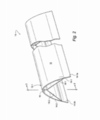
A FIGURA 2 é uma vista em perspectiva ampliada do bordo de ataque resistente a impactos exibido na FIGURA 1; e
A FIGURA 3 é uma vista elevada de uma seção de corte ampliada do bordo de ataque resistente a impactos a partir da linha 3-3 na FIGURA 2.The mentioned structures referring to the present invention will be better understood with reference to the following detailed description of exemplary and illustrative structures without limitation, together with the figures, in which:
FIGURE 1 is a partial perspective view of the tail section of an aircraft showing the representative location of an impact resistant leading edge according to a configuration of the present invention.
FIGURE 2 is an enlarged perspective view of the impact resistant leading edge shown in FIGURE 1; and
FIGURE 3 is an elevated view of an enlarged section of the impact-resistant leading edge from line 3-3 in FIGURE 2.
A FIGURA 1 exibe a porção traseira de uma aeronave AC incluindo a fuselagem F, o estabilizador vertical VS e os estabilizadores horizontais de bombordo e estibordo HSp e HSs respectivamente. Como ilustração exemplificativa, uma estrutura de bordo de ataque resistente a impactos 10 é instalada no estabilizador vertical VS. Deve-se certamente entender que a estrutura de bordo de ataque resistente a impactos 10 poderia ser instalada, de modo similar, nos estabilizadores horizontais HSp e HSs, assim como nas asas e, caso existam, nos canards (não exibidos).FIGURE 1 shows the rear portion of an AC aircraft including the fuselage F, the vertical VS stabilizer and the horizontal port and starboard stabilizers HSp and HSs respectively. As an example, an impact resistant leading edge structure 10 is installed on the VS vertical stabilizer. It should certainly be understood that the impact resistant leading edge structure 10 could be installed, in a similar way, on the horizontal stabilizers HSp and HSs, as well as on the wings and, if any, on the canards (not shown).
Como talvez esteja mais claro nas FIGURAS 2 e 3, a estrutura de bordo de ataque resistente a impactos 10 inclui um revestimento externo arqueado 12 com uma extremidade apical 12-1 que se opõe estruturalmente a objetos que se aproximem em direção oposta, quando a aeronave AC estiver em voo (marcado pela seta Ao na FIGURA 3). Os segmentos do revestimento 14-1 e 14-2 se estendem em forma de arco a partir da extremidade apical 12-1 e terminam em um respectivo par de extremidades de fixação espaçadas lateralmente a e 14-2a. Estas extremidades de fixação 14-1a e 14-2a servem para fixar a estrutura do bordo de ataque 10 à estrutura da aeronave projetada para proteger (que, na representação ilustrada, é o estabilizador vertical VS).As is perhaps clearer in FIGURES 2 and 3, the impact-resistant leading edge structure 10 includes an arched outer shell 12 with an apical end 12-1 that is structurally opposed to objects approaching in the opposite direction when the aircraft AC is in flight (marked by the arrow Ao in FIGURE 3). The cladding segments 14-1 and 14-2 extend in an arc form from the apical end 12-1 and terminate in a respective pair of securing ends spaced laterally at and 14-2a. These fixation ends 14-1a and 14-2a serve to fix the leading edge structure 10 to the aircraft structure designed to protect (which, in the illustrated illustration, is the vertical VS stabilizer).
A estrutura do bordo de ataque 10 inclui um reforço estrutural interno, geralmente em forma de Y, que se estende continuamente por todo o seu comprimento longitudinal. Especificamente, a estrutura do bordo de ataque 10 é, de preferência, formada por um perfil de reforço interno 16 e um par de braços de reforço 18-1 e 18-2. O perfil 16 é, preferencialmente, um elemento estrutural planar posicionado imediatamente atrás da extremidade apical 12-1 do revestimento 12 ao longo do plano de bisseção longitudinal BP (veja FIGURA 3). Desta forma, a extremidade frontal do perfil 16 é integrada com o revestimento 12 imediatamente atrás da extremidade apical 12-1. Os braços de reforço planar 18-1 e 18-2 estendem-se assim da extremidade posterior do perfil 16 em direções divergentes até as extremidades de fixação 14-la e 14-2a dos segmentos do revestimento 14-1 e 14-2, respectivamente. Desta maneira, o perfil 16 e os braços de reforço 18-1 e 18-2 são integralmente fixados um ao outro e ao revestimento 12 para formar uma estrutura de uma só peça.The leading edge structure 10 includes an internal structural reinforcement, generally in the form of a Y, which continuously extends along its longitudinal length. Specifically, the leading edge structure 10 is preferably formed by an internal reinforcement profile 16 and a pair of reinforcement arms 18-1 and 18-2. The profile 16 is preferably a planar structural element positioned immediately behind the apical end 12-1 of the liner 12 along the longitudinal bisection plane BP (see FIGURE 3). In this way, the front end of the profile 16 is integrated with the coating 12 immediately behind the apical end 12-1. The planar reinforcement arms 18-1 and 18-2 thus extend from the rear end of the profile 16 in divergent directions to the fixing ends 14-la and 14-2a of the cladding segments 14-1 and 14-2, respectively . In this way, the profile 16 and the reinforcement arms 18-1 and 18-2 are integrally attached to each other and to the coating 12 to form a one-piece structure.
Conforme brevemente observado acima, a estrutura do bordo de ataque resistente a impactos 10 é, de preferência, moldada como um componente estrutural integral (uma só peça) com materiais compostos reforçados com fibras, apresentando uma razão resistência/peso e rigidez/peso relativamente alta. Materiais compostos são geralmente descritos como sendo materiais que incluem um ou mais tipos de fibras de reforço, como fibras de vidro, de aramida (por exemplo, fibras de aramida KEVLAR®), fibras de carbono e similares, incorporadas em uma matriz polimérica, como uma resina epóxi. A preferência para a construção da presente invenção é pela fibra de vidro. Os componentes da estrutura de bordo de ataque 10, conforme discutido previamente, podem ser moldados em uma estrutura integrada, por meio da laminação e da cura conjunta dos materiais compostos reforçados com fibras.As briefly noted above, the impact-resistant leading edge structure 10 is preferably shaped as an integral structural component (one piece) with fiber-reinforced composite materials, presenting a relatively high strength / weight and stiffness / weight ratio . Composite materials are generally described as materials that include one or more types of reinforcement fibers, such as glass, aramid fibers (for example, KEVLAR® aramid fibers), carbon fibers and the like, incorporated into a polymeric matrix, such as an epoxy resin. The preference for the construction of the present invention is fiberglass. The components of the leading edge structure 10, as previously discussed, can be molded into an integrated structure, by laminating and curing the fiber-reinforced composite materials together.
Deve ser ainda observado, por exemplo, na FIGURA 3, que a extremidade apical 12-1 do revestimento 12 apresenta uma seção transversal do material composto de maior espessura se comparada com as extremidades de fixação 12-la e 12-2a. Além disso, as seções frontais dos braços de reforço 18-1 e 18-2 têm uma seção transversal do material composto de maior espessura se comparadas com o perfil 16. Esta maior espessura da seção transversal dos componentes contribui para uma maior rigidez e, por conseguinte, para as propriedades de resistência a impactos.It should also be noted, for example, in FIGURE 3, that the apical end 12-1 of the coating 12 has a cross section of the composite material of greater thickness compared to the fixation ends 12-la and 12-2a. In addition, the front sections of the reinforcement arms 18-1 and 18-2 have a thicker cross-section of the composite material compared to the profile 16. This greater cross-section thickness of the components contributes to greater rigidity and, therefore, therefore for impact resistance properties.
Os materiais compostos com os quais o bordo de ataque 10 é construído são preferencialmente não-condutores, de forma a permitir a instalação em seu interior de antenas de alta-frequência (AF) ou outros componentes de aviônicos que requerem isolamento elétrico.The composite materials with which the leading edge 10 is constructed are preferably non-conductive, in order to allow the installation of high frequency (AF) antennas or other avionics components that require electrical insulation inside.
Além de ser capaz de suportar impactos de aves para atender às FARs e a outros requisitos de certificações internacionais equivalentes, as estruturas de bordo de ataque da presente invenção são mais leves se comparadas com as splitter plates convencionais. Ademais, desde que as estruturas de bordo de ataque 10 têm a forma de um componente único, a montagem na aeronave é simplificada.In addition to being able to withstand bird impacts to meet FARs and other requirements of equivalent international certifications, the leading edge structures of the present invention are lighter compared to conventional splitter plates. Furthermore, since the leading edge structures 10 are in the form of a single component, assembly on the aircraft is simplified.
Assim, apesar da invenção ter sido descrita com relação ao que é considerado presentemente uma realização mais prática e preferida, deve-se entender que a invenção não se limita à realização revelada, mas, pelo contrário, seu objetivo é cobrir as diversas modificações e disposições equivalentes incluídas em seu espírito e escopo.Thus, although the invention has been described in relation to what is presently considered to be a more practical and preferred embodiment, it should be understood that the invention is not limited to the revealed embodiment, but, on the contrary, its objective is to cover the various modifications and provisions equivalents included in its spirit and scope.
Claims (9)
um revestimento arqueado (12) com uma extremidade apical (12-1); e
um reforço interno, em forma geral de Y, que se estende longitudinal e integralmente ligado ao revestimento arqueado (12), em que o reforço interno que se estende longitudinalmente inclui um elemento de nervura de reforço interno (16) e um par de braços de reforço planar divergentes (18-1, 18-2), caracterizada pelo fato de que a extremidade anterior do perfil ser integralmente ligada na parte posterior da extremidade apical do revestimento e em que a extremidade posterior do perfil é integralmente ligada à cada um dos braços de reforço.Aircraft leading edge structure (10), comprising:
an arcuate liner (12) with an apical end (12-1); and
an internal reinforcement, in general Y shape, which extends longitudinally and integrally connected to the arcuate covering (12), in which the internal reinforcement which extends longitudinally includes an internal reinforcement rib element (16) and a pair of divergent planar reinforcement (18-1, 18-2), characterized by the fact that the anterior end of the profile is integrally connected at the rear of the apical end of the lining and in which the posterior end of the profile is integrally connected to each of the arms reinforcement.
Applications Claiming Priority (2)
| Application Number | Priority Date | Filing Date | Title |
|---|---|---|---|
| US12/335,524 US8123167B2 (en) | 2008-12-15 | 2008-12-15 | Impact resistant aircraft leading edge structures and aircraft including the same |
| US12/335.524 | 2008-12-15 |
Publications (2)
| Publication Number | Publication Date |
|---|---|
| BRPI0925220A2 BRPI0925220A2 (en) | 2017-02-14 |
| BRPI0925220B1 true BRPI0925220B1 (en) | 2020-07-21 |
Family
ID=41694616
Family Applications (1)
| Application Number | Title | Priority Date | Filing Date |
|---|---|---|---|
| BRPI0925220-7A BRPI0925220B1 (en) | 2008-12-15 | 2009-12-15 | aircraft impact carrier aircraft structure and method for providing resistance to an aircraft |
Country Status (4)
| Country | Link |
|---|---|
| US (1) | US8123167B2 (en) |
| EP (1) | EP2196391B1 (en) |
| CN (1) | CN101786499B (en) |
| BR (1) | BRPI0925220B1 (en) |
Families Citing this family (28)
| Publication number | Priority date | Publication date | Assignee | Title |
|---|---|---|---|---|
| FI20080208L (en) | 2008-03-13 | 2008-03-27 | Patria Aerostructures Oy | Aircraft leading edge element, method of making the same, and wing and stabilizer |
| ITTO20080333A1 (en) * | 2008-05-06 | 2009-11-07 | Alenia Aeronautica Spa | ATTACHMENT EDGE FOR WING STRUCTURES AND THERMOPLASTIC TENNES WITH DOUBLE IRRIGID STRUCTURE. |
| GB2471408B (en) * | 2009-03-12 | 2011-03-09 | Patria Aerostructures Oy | Leading edge element of aircraft, method for manufacturing one, wing and stabilizer |
| DE102010036154B4 (en) * | 2010-09-02 | 2017-01-26 | Airbus Operations Gmbh | An air-sucking vehicle body component, method for manufacturing an air-sucking vehicle body component and vehicle, in particular aircraft, with an air-sucking vehicle body component |
| CN102390520B (en) * | 2011-09-29 | 2014-06-18 | 西北工业大学 | Empennage capable of improving bird strike resistance of airplane |
| GB201120707D0 (en) * | 2011-12-01 | 2012-01-11 | Airbus Operations Ltd | Leading edge structure |
| US9708030B1 (en) | 2011-12-08 | 2017-07-18 | The Boeing Company | Impact-energy tolerant method and structures |
| ES2421410B1 (en) * | 2012-02-29 | 2014-10-28 | Airbus Operations, S.L. | EDGE EDGE OF AN AIRCRAFT SURFACE OF AN AIRCRAFT |
| FR2989666B1 (en) | 2012-04-19 | 2014-12-05 | Eurocopter France | AIRCRAFT AERODYNAMIC SURFACE, AND AIRCRAFT PROVIDED WITH SAID AERODYNAMIC SURFACE |
| US8968437B2 (en) * | 2012-05-02 | 2015-03-03 | Michael J Kline | Jet engine with deflector |
| EP2687436B1 (en) * | 2012-07-17 | 2016-08-31 | Airbus Operations, S.L. | Highly integrated leading edge of an aircraft lifting surface |
| EP2690008B1 (en) * | 2012-07-26 | 2015-06-10 | AIRBUS HELICOPTERS DEUTSCHLAND GmbH | Helicopter with an aerodynamic, blunt aft body |
| FR2993857B1 (en) * | 2012-07-26 | 2015-03-27 | Airbus Operations Sas | DEVICE FOR PROTECTING A LONGERON STRUCTURE BEFORE A CENTRAL AIRCRAFT WING BOX AND AT LEAST ONE EQUIPMENT LOCATED IN THE SAME |
| FR2999344B1 (en) * | 2012-12-10 | 2018-04-13 | Airbus Operations | ON-BOARD METEOROLOGICAL RADAR ANTENNA FOR AIRCRAFT AND ASSOCIATED AIRCRAFT |
| EP2886449A1 (en) | 2013-12-23 | 2015-06-24 | Airbus Operations S.L. | Leading edge for an aircraft lifting surface |
| EP2962840A1 (en) * | 2014-06-30 | 2016-01-06 | Airbus Operations, S.L. | A leading edge for an aircraft lifting surface and manufacturing method thereof |
| JP6782533B2 (en) * | 2015-08-26 | 2020-11-11 | 三菱航空機株式会社 | Aircraft leading edge structure, aircraft wing and aircraft |
| EP3219458B1 (en) * | 2016-03-14 | 2019-05-08 | Airbus Operations, S.L. | Method and injection moulding tool for manufacturing a leading edge section with hybrid laminar flow control for an aircraft |
| CN107434031A (en) * | 2016-05-25 | 2017-12-05 | 空中客车简化股份公司 | The structure member of aircraft wing body and the aircraft including the structure member |
| EP3335986B1 (en) * | 2016-12-19 | 2019-11-20 | Airbus Operations S.L. | Impact resistant dorsal fin |
| US10556701B2 (en) * | 2017-04-14 | 2020-02-11 | Rohr, Inc. | Bird-strike energy absorbing net |
| US11454121B2 (en) * | 2018-09-28 | 2022-09-27 | General Electric Company | Airfoil with leading edge guard |
| US11518502B2 (en) * | 2019-04-30 | 2022-12-06 | Textron Innovations Inc. | Energy absorption stabilizers and methods |
| CN112249300B (en) * | 2020-10-22 | 2022-02-15 | 航天特种材料及工艺技术研究所 | Carbon fiber composite material airfoil leading edge structure |
| US11725524B2 (en) | 2021-03-26 | 2023-08-15 | General Electric Company | Engine airfoil metal edge |
| CN113772108B (en) * | 2021-09-15 | 2023-08-04 | 中国航空工业集团公司西安飞机设计研究所 | Tail wing front edge bird divider structure |
| US11655828B2 (en) | 2021-10-27 | 2023-05-23 | General Electric Company | Anti-icing systems and airfoils for a fan section of a turbine engine |
| US11767607B1 (en) | 2022-07-13 | 2023-09-26 | General Electric Company | Method of depositing a metal layer on a component |
Family Cites Families (12)
| Publication number | Priority date | Publication date | Assignee | Title |
|---|---|---|---|---|
| FR2381662A1 (en) * | 1977-02-28 | 1978-09-22 | Aerospatiale | BLADE, ESPECIALLY FOR A HELICOPTER ROTOR, AND ITS MANUFACTURING PROCESS |
| US4485991A (en) * | 1983-07-01 | 1984-12-04 | Fuller Brian L | Rollable airfoil |
| US4657615A (en) * | 1984-08-20 | 1987-04-14 | The Boeing Company | Composite leading edge/spar member for an aircraft control surface |
| JP3647612B2 (en) * | 1997-07-24 | 2005-05-18 | 富士重工業株式会社 | Aircraft leading edge structure and manufacturing method thereof |
| WO2005030577A1 (en) * | 2003-08-27 | 2005-04-07 | Bell Helicopter Textron Inc. | Protective skin for aircraft |
| WO2007007138A1 (en) | 2005-07-14 | 2007-01-18 | Telefonaktiebolaget Lm Ericsson (Publ) | Model set adaptation by probability mass diffusion |
| EP1764307A1 (en) * | 2005-09-14 | 2007-03-21 | EADS Construcciones Aeronauticas, S.A. | Process for manufacturing a monolithic leading edge |
| DE102005060958A1 (en) | 2005-12-20 | 2007-06-21 | Airbus Deutschland Gmbh | Aircraft structure protection, against damage from birds in flight, is an outer skin of glass fiber reinforced aluminum with a hollow zone to allow skin distortion through an impact |
| US7997529B2 (en) * | 2006-01-19 | 2011-08-16 | The Boeing Company | Compliant panel for aircraft |
| GB2440133A (en) * | 2006-07-18 | 2008-01-23 | Gkn Aerospace Transparency Sys | A de-icing heated leading edge component of an aircraft |
| ES2329324B1 (en) * | 2007-03-30 | 2010-09-06 | Airbus España, S.L. | REINFORCED COMPOSITE MATERIAL AIRCRAFT ATTACK EDGE. |
| US7857588B2 (en) * | 2007-07-06 | 2010-12-28 | United Technologies Corporation | Reinforced airfoils |
-
2008
- 2008-12-15 US US12/335,524 patent/US8123167B2/en active Active
-
2009
- 2009-12-15 EP EP09015475.8A patent/EP2196391B1/en active Active
- 2009-12-15 CN CN200911000128.3A patent/CN101786499B/en active Active
- 2009-12-15 BR BRPI0925220-7A patent/BRPI0925220B1/en active IP Right Grant
Also Published As
| Publication number | Publication date |
|---|---|
| EP2196391B1 (en) | 2016-07-27 |
| US8123167B2 (en) | 2012-02-28 |
| CN101786499B (en) | 2014-11-26 |
| EP2196391A3 (en) | 2012-03-28 |
| EP2196391A2 (en) | 2010-06-16 |
| CN101786499A (en) | 2010-07-28 |
| US20100148006A1 (en) | 2010-06-17 |
| BRPI0925220A2 (en) | 2017-02-14 |
Similar Documents
| Publication | Publication Date | Title |
|---|---|---|
| BRPI0925220B1 (en) | aircraft impact carrier aircraft structure and method for providing resistance to an aircraft | |
| ES2674938T3 (en) | Lower joints between outer wing drawers and central wing sections of aircraft wing assemblies | |
| ES2609598T3 (en) | Permanently curved beam and manufacturing method | |
| US9328630B2 (en) | Lateral propulsion unit for aircraft comprising a turbine engine support arch | |
| ES2592633T3 (en) | Aircraft fuselage impact resistant and improved damage tolerant | |
| ES2450054T3 (en) | Elastic aircraft panel | |
| CN103183128B (en) | Interior shield, aircraft with interior shield and associated method | |
| US10099434B2 (en) | Composite airfoil structures | |
| ES2399173T3 (en) | Aircraft pressure bulkhead | |
| US4696623A (en) | Helicopter rotor blade made from a multispar composite material with torsion compartments and a process for manufacturing same | |
| ES2352220T3 (en) | AIRCRAFT WING COMPOSED OF COMPOSITE AND METALLIC MATERIAL PANELS. | |
| BR112015013094B1 (en) | COMPOSITE MATERIAL STRUCTURE COMPRISING AT LEAST ONE REINFORCEMENT MATERIAL AND AT LEAST ONE MATRIX MATERIAL | |
| US9248900B2 (en) | Tip fairing of a horizontal airfoil of an aircraft | |
| BRPI0621804A2 (en) | aircraft fuselage assembly concept | |
| BR102013027906B1 (en) | CIRCUMFERENCE AMENDMENT TO JOIN CASING STRUCTURES AND METHOD OF JOINING A CASING STRUCTURE | |
| KR20150107586A (en) | One piece inlet lip skin design | |
| JPH06508801A (en) | Structural components | |
| ES2744569T3 (en) | Armored leading edge and manufacturing procedure thereof | |
| WO2008092970A1 (en) | Aircraft loading frame of composite material | |
| ES2794623T3 (en) | Integrated removable ballistic armor | |
| BRPI0614230A2 (en) | primary structure of aircraft engine stirrup | |
| BR112016020521A2 (en) | COMPOSITE MATERIAL STRUCTURE, AIRPLANE WING AND AIRPLANE FUSELAGE WITH THE SAME AND METHOD FOR MANUFACTURING COMPOSITE MATERIAL STRUCTURE | |
| ES2474466T3 (en) | Fuselage element that includes a fuselage section and joining means, fuselage portion, fuselage and aircraft | |
| BR112014007715B1 (en) | ACCESS DOOR ASSEMBLY AND METHOD OF CREATION OF IT | |
| US11027852B2 (en) | Assembly for aircraft comprising a primary mounting pylon structure fixed to an airfoil box using a bolted link |
Legal Events
| Date | Code | Title | Description |
|---|---|---|---|
| B03A | Publication of a patent application or of a certificate of addition of invention [chapter 3.1 patent gazette] | ||
| B08F | Application fees: application dismissed [chapter 8.6 patent gazette] | ||
| B08G | Application fees: restoration [chapter 8.7 patent gazette] | ||
| B06F | Objections, documents and/or translations needed after an examination request according [chapter 6.6 patent gazette] | ||
| B06U | Preliminary requirement: requests with searches performed by other patent offices: procedure suspended [chapter 6.21 patent gazette] | ||
| B09A | Decision: intention to grant [chapter 9.1 patent gazette] | ||
| B16A | Patent or certificate of addition of invention granted |
Free format text: PRAZO DE VALIDADE: 10 (DEZ) ANOS CONTADOS A PARTIR DE 21/07/2020, OBSERVADAS AS CONDICOES LEGAIS. |
|
| B25D | Requested change of name of applicant approved |
Owner name: EMBRAER S.A. (BR/SP) |