BRPI0924120B1 - method for purifying exhaust gas from a diesel engine in a system - Google Patents
method for purifying exhaust gas from a diesel engine in a system Download PDFInfo
- Publication number
- BRPI0924120B1 BRPI0924120B1 BRPI0924120-5A BRPI0924120A BRPI0924120B1 BR PI0924120 B1 BRPI0924120 B1 BR PI0924120B1 BR PI0924120 A BRPI0924120 A BR PI0924120A BR PI0924120 B1 BRPI0924120 B1 BR PI0924120B1
- Authority
- BR
- Brazil
- Prior art keywords
- catalyst
- oxide
- fact
- selective catalytic
- catalytic reduction
- Prior art date
Links
Images

Classifications
-
- F—MECHANICAL ENGINEERING; LIGHTING; HEATING; WEAPONS; BLASTING
- F01—MACHINES OR ENGINES IN GENERAL; ENGINE PLANTS IN GENERAL; STEAM ENGINES
- F01N—GAS-FLOW SILENCERS OR EXHAUST APPARATUS FOR MACHINES OR ENGINES IN GENERAL; GAS-FLOW SILENCERS OR EXHAUST APPARATUS FOR INTERNAL COMBUSTION ENGINES
- F01N3/00—Exhaust or silencing apparatus having means for purifying, rendering innocuous, or otherwise treating exhaust
- F01N3/02—Exhaust or silencing apparatus having means for purifying, rendering innocuous, or otherwise treating exhaust for cooling, or for removing solid constituents of, exhaust
- F01N3/021—Exhaust or silencing apparatus having means for purifying, rendering innocuous, or otherwise treating exhaust for cooling, or for removing solid constituents of, exhaust by means of filters
- F01N3/023—Exhaust or silencing apparatus having means for purifying, rendering innocuous, or otherwise treating exhaust for cooling, or for removing solid constituents of, exhaust by means of filters using means for regenerating the filters, e.g. by burning trapped particles
-
- B—PERFORMING OPERATIONS; TRANSPORTING
- B01—PHYSICAL OR CHEMICAL PROCESSES OR APPARATUS IN GENERAL
- B01D—SEPARATION
- B01D53/00—Separation of gases or vapours; Recovering vapours of volatile solvents from gases; Chemical or biological purification of waste gases, e.g. engine exhaust gases, smoke, fumes, flue gases, aerosols
- B01D53/34—Chemical or biological purification of waste gases
- B01D53/92—Chemical or biological purification of waste gases of engine exhaust gases
- B01D53/94—Chemical or biological purification of waste gases of engine exhaust gases by catalytic processes
- B01D53/944—Simultaneously removing carbon monoxide, hydrocarbons or carbon making use of oxidation catalysts
-
- B—PERFORMING OPERATIONS; TRANSPORTING
- B01—PHYSICAL OR CHEMICAL PROCESSES OR APPARATUS IN GENERAL
- B01D—SEPARATION
- B01D53/00—Separation of gases or vapours; Recovering vapours of volatile solvents from gases; Chemical or biological purification of waste gases, e.g. engine exhaust gases, smoke, fumes, flue gases, aerosols
- B01D53/34—Chemical or biological purification of waste gases
- B01D53/92—Chemical or biological purification of waste gases of engine exhaust gases
- B01D53/94—Chemical or biological purification of waste gases of engine exhaust gases by catalytic processes
- B01D53/9459—Removing one or more of nitrogen oxides, carbon monoxide, or hydrocarbons by multiple successive catalytic functions; systems with more than one different function, e.g. zone coated catalysts
- B01D53/9477—Removing one or more of nitrogen oxides, carbon monoxide, or hydrocarbons by multiple successive catalytic functions; systems with more than one different function, e.g. zone coated catalysts with catalysts positioned on separate bricks, e.g. exhaust systems
-
- F—MECHANICAL ENGINEERING; LIGHTING; HEATING; WEAPONS; BLASTING
- F01—MACHINES OR ENGINES IN GENERAL; ENGINE PLANTS IN GENERAL; STEAM ENGINES
- F01N—GAS-FLOW SILENCERS OR EXHAUST APPARATUS FOR MACHINES OR ENGINES IN GENERAL; GAS-FLOW SILENCERS OR EXHAUST APPARATUS FOR INTERNAL COMBUSTION ENGINES
- F01N13/00—Exhaust or silencing apparatus characterised by constructional features ; Exhaust or silencing apparatus, or parts thereof, having pertinent characteristics not provided for in, or of interest apart from, groups F01N1/00 - F01N5/00, F01N9/00, F01N11/00
- F01N13/009—Exhaust or silencing apparatus characterised by constructional features ; Exhaust or silencing apparatus, or parts thereof, having pertinent characteristics not provided for in, or of interest apart from, groups F01N1/00 - F01N5/00, F01N9/00, F01N11/00 having two or more separate purifying devices arranged in series
- F01N13/0093—Exhaust or silencing apparatus characterised by constructional features ; Exhaust or silencing apparatus, or parts thereof, having pertinent characteristics not provided for in, or of interest apart from, groups F01N1/00 - F01N5/00, F01N9/00, F01N11/00 having two or more separate purifying devices arranged in series the purifying devices are of the same type
-
- F—MECHANICAL ENGINEERING; LIGHTING; HEATING; WEAPONS; BLASTING
- F01—MACHINES OR ENGINES IN GENERAL; ENGINE PLANTS IN GENERAL; STEAM ENGINES
- F01N—GAS-FLOW SILENCERS OR EXHAUST APPARATUS FOR MACHINES OR ENGINES IN GENERAL; GAS-FLOW SILENCERS OR EXHAUST APPARATUS FOR INTERNAL COMBUSTION ENGINES
- F01N3/00—Exhaust or silencing apparatus having means for purifying, rendering innocuous, or otherwise treating exhaust
- F01N3/02—Exhaust or silencing apparatus having means for purifying, rendering innocuous, or otherwise treating exhaust for cooling, or for removing solid constituents of, exhaust
- F01N3/021—Exhaust or silencing apparatus having means for purifying, rendering innocuous, or otherwise treating exhaust for cooling, or for removing solid constituents of, exhaust by means of filters
- F01N3/023—Exhaust or silencing apparatus having means for purifying, rendering innocuous, or otherwise treating exhaust for cooling, or for removing solid constituents of, exhaust by means of filters using means for regenerating the filters, e.g. by burning trapped particles
- F01N3/025—Exhaust or silencing apparatus having means for purifying, rendering innocuous, or otherwise treating exhaust for cooling, or for removing solid constituents of, exhaust by means of filters using means for regenerating the filters, e.g. by burning trapped particles using fuel burner or by adding fuel to exhaust
- F01N3/0253—Exhaust or silencing apparatus having means for purifying, rendering innocuous, or otherwise treating exhaust for cooling, or for removing solid constituents of, exhaust by means of filters using means for regenerating the filters, e.g. by burning trapped particles using fuel burner or by adding fuel to exhaust adding fuel to exhaust gases
-
- F—MECHANICAL ENGINEERING; LIGHTING; HEATING; WEAPONS; BLASTING
- F01—MACHINES OR ENGINES IN GENERAL; ENGINE PLANTS IN GENERAL; STEAM ENGINES
- F01N—GAS-FLOW SILENCERS OR EXHAUST APPARATUS FOR MACHINES OR ENGINES IN GENERAL; GAS-FLOW SILENCERS OR EXHAUST APPARATUS FOR INTERNAL COMBUSTION ENGINES
- F01N3/00—Exhaust or silencing apparatus having means for purifying, rendering innocuous, or otherwise treating exhaust
- F01N3/02—Exhaust or silencing apparatus having means for purifying, rendering innocuous, or otherwise treating exhaust for cooling, or for removing solid constituents of, exhaust
- F01N3/021—Exhaust or silencing apparatus having means for purifying, rendering innocuous, or otherwise treating exhaust for cooling, or for removing solid constituents of, exhaust by means of filters
- F01N3/033—Exhaust or silencing apparatus having means for purifying, rendering innocuous, or otherwise treating exhaust for cooling, or for removing solid constituents of, exhaust by means of filters in combination with other devices
- F01N3/035—Exhaust or silencing apparatus having means for purifying, rendering innocuous, or otherwise treating exhaust for cooling, or for removing solid constituents of, exhaust by means of filters in combination with other devices with catalytic reactors, e.g. catalysed diesel particulate filters
-
- F—MECHANICAL ENGINEERING; LIGHTING; HEATING; WEAPONS; BLASTING
- F01—MACHINES OR ENGINES IN GENERAL; ENGINE PLANTS IN GENERAL; STEAM ENGINES
- F01N—GAS-FLOW SILENCERS OR EXHAUST APPARATUS FOR MACHINES OR ENGINES IN GENERAL; GAS-FLOW SILENCERS OR EXHAUST APPARATUS FOR INTERNAL COMBUSTION ENGINES
- F01N3/00—Exhaust or silencing apparatus having means for purifying, rendering innocuous, or otherwise treating exhaust
- F01N3/08—Exhaust or silencing apparatus having means for purifying, rendering innocuous, or otherwise treating exhaust for rendering innocuous
- F01N3/10—Exhaust or silencing apparatus having means for purifying, rendering innocuous, or otherwise treating exhaust for rendering innocuous by thermal or catalytic conversion of noxious components of exhaust
- F01N3/103—Oxidation catalysts for HC and CO only
-
- F—MECHANICAL ENGINEERING; LIGHTING; HEATING; WEAPONS; BLASTING
- F01—MACHINES OR ENGINES IN GENERAL; ENGINE PLANTS IN GENERAL; STEAM ENGINES
- F01N—GAS-FLOW SILENCERS OR EXHAUST APPARATUS FOR MACHINES OR ENGINES IN GENERAL; GAS-FLOW SILENCERS OR EXHAUST APPARATUS FOR INTERNAL COMBUSTION ENGINES
- F01N3/00—Exhaust or silencing apparatus having means for purifying, rendering innocuous, or otherwise treating exhaust
- F01N3/08—Exhaust or silencing apparatus having means for purifying, rendering innocuous, or otherwise treating exhaust for rendering innocuous
- F01N3/10—Exhaust or silencing apparatus having means for purifying, rendering innocuous, or otherwise treating exhaust for rendering innocuous by thermal or catalytic conversion of noxious components of exhaust
- F01N3/105—General auxiliary catalysts, e.g. upstream or downstream of the main catalyst
- F01N3/106—Auxiliary oxidation catalysts
-
- F—MECHANICAL ENGINEERING; LIGHTING; HEATING; WEAPONS; BLASTING
- F01—MACHINES OR ENGINES IN GENERAL; ENGINE PLANTS IN GENERAL; STEAM ENGINES
- F01N—GAS-FLOW SILENCERS OR EXHAUST APPARATUS FOR MACHINES OR ENGINES IN GENERAL; GAS-FLOW SILENCERS OR EXHAUST APPARATUS FOR INTERNAL COMBUSTION ENGINES
- F01N3/00—Exhaust or silencing apparatus having means for purifying, rendering innocuous, or otherwise treating exhaust
- F01N3/08—Exhaust or silencing apparatus having means for purifying, rendering innocuous, or otherwise treating exhaust for rendering innocuous
- F01N3/10—Exhaust or silencing apparatus having means for purifying, rendering innocuous, or otherwise treating exhaust for rendering innocuous by thermal or catalytic conversion of noxious components of exhaust
- F01N3/18—Exhaust or silencing apparatus having means for purifying, rendering innocuous, or otherwise treating exhaust for rendering innocuous by thermal or catalytic conversion of noxious components of exhaust characterised by methods of operation; Control
- F01N3/20—Exhaust or silencing apparatus having means for purifying, rendering innocuous, or otherwise treating exhaust for rendering innocuous by thermal or catalytic conversion of noxious components of exhaust characterised by methods of operation; Control specially adapted for catalytic conversion ; Methods of operation or control of catalytic converters
- F01N3/2066—Selective catalytic reduction [SCR]
- F01N3/208—Control of selective catalytic reduction [SCR], e.g. dosing of reducing agent
-
- F—MECHANICAL ENGINEERING; LIGHTING; HEATING; WEAPONS; BLASTING
- F01—MACHINES OR ENGINES IN GENERAL; ENGINE PLANTS IN GENERAL; STEAM ENGINES
- F01N—GAS-FLOW SILENCERS OR EXHAUST APPARATUS FOR MACHINES OR ENGINES IN GENERAL; GAS-FLOW SILENCERS OR EXHAUST APPARATUS FOR INTERNAL COMBUSTION ENGINES
- F01N9/00—Electrical control of exhaust gas treating apparatus
- F01N9/002—Electrical control of exhaust gas treating apparatus of filter regeneration, e.g. detection of clogging
-
- B—PERFORMING OPERATIONS; TRANSPORTING
- B01—PHYSICAL OR CHEMICAL PROCESSES OR APPARATUS IN GENERAL
- B01D—SEPARATION
- B01D2251/00—Reactants
- B01D2251/20—Reductants
- B01D2251/206—Ammonium compounds
-
- B—PERFORMING OPERATIONS; TRANSPORTING
- B01—PHYSICAL OR CHEMICAL PROCESSES OR APPARATUS IN GENERAL
- B01D—SEPARATION
- B01D2251/00—Reactants
- B01D2251/20—Reductants
- B01D2251/206—Ammonium compounds
- B01D2251/2062—Ammonia
-
- B—PERFORMING OPERATIONS; TRANSPORTING
- B01—PHYSICAL OR CHEMICAL PROCESSES OR APPARATUS IN GENERAL
- B01D—SEPARATION
- B01D2251/00—Reactants
- B01D2251/20—Reductants
- B01D2251/206—Ammonium compounds
- B01D2251/2067—Urea
-
- B—PERFORMING OPERATIONS; TRANSPORTING
- B01—PHYSICAL OR CHEMICAL PROCESSES OR APPARATUS IN GENERAL
- B01D—SEPARATION
- B01D2251/00—Reactants
- B01D2251/20—Reductants
- B01D2251/208—Hydrocarbons
-
- B—PERFORMING OPERATIONS; TRANSPORTING
- B01—PHYSICAL OR CHEMICAL PROCESSES OR APPARATUS IN GENERAL
- B01D—SEPARATION
- B01D2255/00—Catalysts
- B01D2255/10—Noble metals or compounds thereof
- B01D2255/102—Platinum group metals
- B01D2255/1021—Platinum
-
- B—PERFORMING OPERATIONS; TRANSPORTING
- B01—PHYSICAL OR CHEMICAL PROCESSES OR APPARATUS IN GENERAL
- B01D—SEPARATION
- B01D2255/00—Catalysts
- B01D2255/10—Noble metals or compounds thereof
- B01D2255/102—Platinum group metals
- B01D2255/1023—Palladium
-
- B—PERFORMING OPERATIONS; TRANSPORTING
- B01—PHYSICAL OR CHEMICAL PROCESSES OR APPARATUS IN GENERAL
- B01D—SEPARATION
- B01D2255/00—Catalysts
- B01D2255/20—Metals or compounds thereof
- B01D2255/207—Transition metals
- B01D2255/20707—Titanium
-
- B—PERFORMING OPERATIONS; TRANSPORTING
- B01—PHYSICAL OR CHEMICAL PROCESSES OR APPARATUS IN GENERAL
- B01D—SEPARATION
- B01D2255/00—Catalysts
- B01D2255/20—Metals or compounds thereof
- B01D2255/207—Transition metals
- B01D2255/20723—Vanadium
-
- B—PERFORMING OPERATIONS; TRANSPORTING
- B01—PHYSICAL OR CHEMICAL PROCESSES OR APPARATUS IN GENERAL
- B01D—SEPARATION
- B01D2255/00—Catalysts
- B01D2255/20—Metals or compounds thereof
- B01D2255/207—Transition metals
- B01D2255/20738—Iron
-
- B—PERFORMING OPERATIONS; TRANSPORTING
- B01—PHYSICAL OR CHEMICAL PROCESSES OR APPARATUS IN GENERAL
- B01D—SEPARATION
- B01D2255/00—Catalysts
- B01D2255/20—Metals or compounds thereof
- B01D2255/207—Transition metals
- B01D2255/20761—Copper
-
- B—PERFORMING OPERATIONS; TRANSPORTING
- B01—PHYSICAL OR CHEMICAL PROCESSES OR APPARATUS IN GENERAL
- B01D—SEPARATION
- B01D2255/00—Catalysts
- B01D2255/40—Mixed oxides
- B01D2255/407—Zr-Ce mixed oxides
-
- B—PERFORMING OPERATIONS; TRANSPORTING
- B01—PHYSICAL OR CHEMICAL PROCESSES OR APPARATUS IN GENERAL
- B01D—SEPARATION
- B01D2255/00—Catalysts
- B01D2255/50—Zeolites
-
- B—PERFORMING OPERATIONS; TRANSPORTING
- B01—PHYSICAL OR CHEMICAL PROCESSES OR APPARATUS IN GENERAL
- B01D—SEPARATION
- B01D2255/00—Catalysts
- B01D2255/90—Physical characteristics of catalysts
- B01D2255/915—Catalyst supported on particulate filters
-
- B—PERFORMING OPERATIONS; TRANSPORTING
- B01—PHYSICAL OR CHEMICAL PROCESSES OR APPARATUS IN GENERAL
- B01D—SEPARATION
- B01D2258/00—Sources of waste gases
- B01D2258/01—Engine exhaust gases
- B01D2258/012—Diesel engines and lean burn gasoline engines
-
- B—PERFORMING OPERATIONS; TRANSPORTING
- B01—PHYSICAL OR CHEMICAL PROCESSES OR APPARATUS IN GENERAL
- B01D—SEPARATION
- B01D53/00—Separation of gases or vapours; Recovering vapours of volatile solvents from gases; Chemical or biological purification of waste gases, e.g. engine exhaust gases, smoke, fumes, flue gases, aerosols
- B01D53/34—Chemical or biological purification of waste gases
- B01D53/92—Chemical or biological purification of waste gases of engine exhaust gases
- B01D53/94—Chemical or biological purification of waste gases of engine exhaust gases by catalytic processes
- B01D53/9404—Removing only nitrogen compounds
- B01D53/9409—Nitrogen oxides
- B01D53/9413—Processes characterised by a specific catalyst
- B01D53/9418—Processes characterised by a specific catalyst for removing nitrogen oxides by selective catalytic reduction [SCR] using a reducing agent in a lean exhaust gas
-
- B—PERFORMING OPERATIONS; TRANSPORTING
- B01—PHYSICAL OR CHEMICAL PROCESSES OR APPARATUS IN GENERAL
- B01J—CHEMICAL OR PHYSICAL PROCESSES, e.g. CATALYSIS OR COLLOID CHEMISTRY; THEIR RELEVANT APPARATUS
- B01J23/00—Catalysts comprising metals or metal oxides or hydroxides, not provided for in group B01J21/00
- B01J23/16—Catalysts comprising metals or metal oxides or hydroxides, not provided for in group B01J21/00 of arsenic, antimony, bismuth, vanadium, niobium, tantalum, polonium, chromium, molybdenum, tungsten, manganese, technetium or rhenium
- B01J23/20—Vanadium, niobium or tantalum
- B01J23/22—Vanadium
-
- B—PERFORMING OPERATIONS; TRANSPORTING
- B01—PHYSICAL OR CHEMICAL PROCESSES OR APPARATUS IN GENERAL
- B01J—CHEMICAL OR PHYSICAL PROCESSES, e.g. CATALYSIS OR COLLOID CHEMISTRY; THEIR RELEVANT APPARATUS
- B01J29/00—Catalysts comprising molecular sieves
- B01J29/04—Catalysts comprising molecular sieves having base-exchange properties, e.g. crystalline zeolites
- B01J29/06—Crystalline aluminosilicate zeolites; Isomorphous compounds thereof
- B01J29/064—Crystalline aluminosilicate zeolites; Isomorphous compounds thereof containing iron group metals, noble metals or copper
- B01J29/072—Iron group metals or copper
-
- F—MECHANICAL ENGINEERING; LIGHTING; HEATING; WEAPONS; BLASTING
- F01—MACHINES OR ENGINES IN GENERAL; ENGINE PLANTS IN GENERAL; STEAM ENGINES
- F01N—GAS-FLOW SILENCERS OR EXHAUST APPARATUS FOR MACHINES OR ENGINES IN GENERAL; GAS-FLOW SILENCERS OR EXHAUST APPARATUS FOR INTERNAL COMBUSTION ENGINES
- F01N2560/00—Exhaust systems with means for detecting or measuring exhaust gas components or characteristics
- F01N2560/08—Exhaust systems with means for detecting or measuring exhaust gas components or characteristics the means being a pressure sensor
-
- F—MECHANICAL ENGINEERING; LIGHTING; HEATING; WEAPONS; BLASTING
- F01—MACHINES OR ENGINES IN GENERAL; ENGINE PLANTS IN GENERAL; STEAM ENGINES
- F01N—GAS-FLOW SILENCERS OR EXHAUST APPARATUS FOR MACHINES OR ENGINES IN GENERAL; GAS-FLOW SILENCERS OR EXHAUST APPARATUS FOR INTERNAL COMBUSTION ENGINES
- F01N2610/00—Adding substances to exhaust gases
- F01N2610/02—Adding substances to exhaust gases the substance being ammonia or urea
-
- F—MECHANICAL ENGINEERING; LIGHTING; HEATING; WEAPONS; BLASTING
- F01—MACHINES OR ENGINES IN GENERAL; ENGINE PLANTS IN GENERAL; STEAM ENGINES
- F01N—GAS-FLOW SILENCERS OR EXHAUST APPARATUS FOR MACHINES OR ENGINES IN GENERAL; GAS-FLOW SILENCERS OR EXHAUST APPARATUS FOR INTERNAL COMBUSTION ENGINES
- F01N2610/00—Adding substances to exhaust gases
- F01N2610/03—Adding substances to exhaust gases the substance being hydrocarbons, e.g. engine fuel
-
- Y—GENERAL TAGGING OF NEW TECHNOLOGICAL DEVELOPMENTS; GENERAL TAGGING OF CROSS-SECTIONAL TECHNOLOGIES SPANNING OVER SEVERAL SECTIONS OF THE IPC; TECHNICAL SUBJECTS COVERED BY FORMER USPC CROSS-REFERENCE ART COLLECTIONS [XRACs] AND DIGESTS
- Y02—TECHNOLOGIES OR APPLICATIONS FOR MITIGATION OR ADAPTATION AGAINST CLIMATE CHANGE
- Y02T—CLIMATE CHANGE MITIGATION TECHNOLOGIES RELATED TO TRANSPORTATION
- Y02T10/00—Road transport of goods or passengers
- Y02T10/10—Internal combustion engine [ICE] based vehicles
- Y02T10/12—Improving ICE efficiencies
-
- Y—GENERAL TAGGING OF NEW TECHNOLOGICAL DEVELOPMENTS; GENERAL TAGGING OF CROSS-SECTIONAL TECHNOLOGIES SPANNING OVER SEVERAL SECTIONS OF THE IPC; TECHNICAL SUBJECTS COVERED BY FORMER USPC CROSS-REFERENCE ART COLLECTIONS [XRACs] AND DIGESTS
- Y02—TECHNOLOGIES OR APPLICATIONS FOR MITIGATION OR ADAPTATION AGAINST CLIMATE CHANGE
- Y02T—CLIMATE CHANGE MITIGATION TECHNOLOGIES RELATED TO TRANSPORTATION
- Y02T10/00—Road transport of goods or passengers
- Y02T10/10—Internal combustion engine [ICE] based vehicles
- Y02T10/40—Engine management systems
Abstract
MÉTODO PARA PURIFICAÇÃO GÁS DE ESCAPE DE UM MOTOR A DIESEL EM UM SISTEMA, E, SISTEMA. A invenção provê um método para purificação de gás de escape de um motor a diesel em um sistema, que compreende um dispositivo para redução catalítica seletiva e um filtro de particulados de diesel preferivelmente pelo menos parcialmente coberto por uma camada catalítica instalada a jusante do dispositivo para redução catalítica seletiva. Um dispositivo para oxidação catalítica é instalado a montante do dispositivo para redução catalítica seletiva e/ou entre o dispositivo para redução catalítica seletiva e o filtro de particulados de diesel. Um dispositivo para injeção de uma quantidade controlada de agente redutor é instalado na entrada do dispositivo para redução catalítica seletiva, e um dispositivo para injeção de uma quantidade controlada de hidrocarbonetos é instalado na entrada da oxidação catalítica.METHOD FOR PURIFICATION OF EXHAUST GAS FROM A DIESEL ENGINE IN A SYSTEM, AND, SYSTEM. The invention provides a method for purifying exhaust gas from a diesel engine in a system, which comprises a device for selective catalytic reduction and a diesel particulate filter preferably at least partially covered by a catalytic layer installed downstream of the device for selective catalytic reduction. A device for catalytic oxidation is installed upstream of the device for selective catalytic reduction and / or between the device for selective catalytic reduction and the diesel particulate filter. A device for injection of a controlled amount of reducing agent is installed at the entrance of the device for selective catalytic reduction, and a device for injection of a controlled amount of hydrocarbons is installed at the entrance of the catalytic oxidation.
Description
A invenção refere-se à purificação de gás de escape de um motor adiesel. Partículas, hidrocarbonetos de combustão incompleta, óxido de carbono,CO, e óxido de nitrogênio, NOX são removidos do gás de escape.The invention relates to the purification of exhaust gas from an adiesel engine. Particles, incomplete combustion hydrocarbons, carbon oxide, CO, and nitrogen oxide, NOX are removed from the exhaust gas.
A invenção é especificamente dirigida a um método de purificaçãoincluindo um método efetivo, mas simples, para regeneração de filtro.Métodos para purificação de gás de escape já são conhecidos. EmUS 6.863.874 um método é descrito, onde impurezas em um gás de escape sãoremovidas por oxidação seguida por um filtro, onde fuligem é oxidada pordióxido de nitrogênio e oxigênio. Ainda mais a jusante, agente redutor a jusanteé injetado na entrada de um absorvedor de NOX e subsequentemente é instaladoum catalisador de três vias ou um catalisador para redução seletiva.The invention is specifically directed to a purification method including an effective but simple method for filter regeneration. Methods for purifying exhaust gas are already known. In US 6,863,874 a method is described, where impurities in an exhaust gas are removed by oxidation followed by a filter, where soot is oxidized by nitrogen dioxide and oxygen. Further downstream, downstream reducing agent is injected into the entrance of a NOX absorber and subsequently a three-way catalyst or a catalyst for selective reduction is installed.
Outro processo é descrito em US 6.696.031, onde impurezas sãoremovidas por oxidação, filtragem, e redução catalítica seletiva (SCR). Amóniaé injetada a montante da oxidação ou SCR, e ainda a jusante disto, é instaladoum catalisador de pré-oxidação, em que hidrocarboneto pode ser introduzido.Um computador deve controlar as duas correntes de amónia.Another process is described in US 6,696,031, where impurities are removed by oxidation, filtration, and selective catalytic reduction (SCR). Ammonia is injected upstream of the oxidation or SCR, and further downstream, a pre-oxidation catalyst is installed, in which hydrocarbon can be introduced. A computer must control the two ammonia streams.
Impurezas de um gás de escape são, de acordo com método de US6.871.489, removidas passando o gás através de um catalisador de oxidação,um resfriador, equipado com um desvio, uma seção de SCR incluindo injeçãode uréia, através de um aquecedor e finalmente um filtro de particulados dediesel. Dessa forma, o filtro deve ser regenerado elevando a temperatura dofiltro aumentando a produção de calor do aquecedor.Exhaust gas impurities are, according to the method of US6.871.489, removed by passing the gas through an oxidation catalyst, a cooler, equipped with a bypass, an SCR section including urea injection, through a heater and finally a diesel particulate filter. Thus, the filter must be regenerated by raising the temperature of the filter, increasing the heat production of the heater.
Estes processos são ou complicados, necessitam de muita energiaou têm uma decomposição lenta de uréia simultaneamente com reduçãocatalítica lenta de NOX em motores de partida a frio.These processes are either complicated, require a lot of energy or have a slow urea decomposition simultaneously with a slow catalytic reduction of NOX in cold starting engines.
É o objeto geral dessa invenção prover um processo de 2purificação, que efetivamente remove partículas, hidrocarbonetos queimados incompletamente, óxido de carbono, CO, e óxido de nitrogênio, NOX, de um gás de escape e regenera o filtro e ao mesmo tempo é muito simples.A invenção provê um método para a purificação gás de escape de 5 um motor a diesel em um sistema, que compreende um dispositivo para redução catalítica seletiva e um filtro de particulados de diesel preferivelmente pelo menos parcialmente coberto por uma camada catalítica e instalado a jusante do dispositivo para redução catalítica seletiva. Um dispositivo para oxidação catalítica é instalado a montante do dispositivo para redução catalítica 10 seletiva e/ou entre o dispositivo para redução catalítica seletiva e o filtro de particulado de diesel catalisado. Um dispositivo para injeção de uma quantidade controlada de agente redutor é instalado na entrada do dispositivo para redução catalítica seletiva, e um dispositivo para injeção de uma quantidade controlada de hidrocarbonetos é instalado na entrada da oxidação 15 catalítica.A invenção provê que o filtro de particulados de diesel catalisado é passivamente regenerado fechando a injeção de agente redutor e o filtro de particulado de diesel catalisado é ativamente regenerado abrindo para a injeção de entrada de hidrocarboneto de pelo menos um dispositivo para oxidação20 catalítica e opcionalmente fechando para a injeção de agente redutor. O filtro é passivamente regenerado por NO2 a uma temperatura até 500°C e ativamente * regenerado em uma temperatura de 500°C a 700°C.O agente redutor é amónia, solução aquosa de amónia, uréia, uma solução aquosa de uréia, ácido cianúrico. Outros reagentes potenciais à base de 25 nitrogênio incluem amelida, alemina, cianato de amónio, biureto, carbamato de amónio, carbonato de amónio, formato de amónio, melamina, e tricianouréia. Amónia, solução aquosa de amónia, uréia, uma solução aquosa de uréia, ácido cianúrico são preferidas. 510152025O hidrocarboneto é combustível, preferivelmente combustível parao motor a diesel. A redução catalítica seletiva ocorre em presença de umcatalisador à base de vanádio, ou um catalisador à base de zeólito, ou umamistura de óxido de metal de base ácida funcionalizado. O catalisador à base devanádio é óxido de vanádio sobre óxido de titânio com possível adição deóxidos de tungsténio ou molibdênio. O catalisador à base de zeólitocompreende beta zeólito modificado com cobre e/ou ferro, ZSM-5 ou chabasitae a mistura de óxido de metal de base ácida funcionalizado compreendemisturas de óxido de cério-zircônio ácido e misturas de óxido de titânio-zircônio. O catalisador à base de vanádio é usado de 150 °C a 550°C e ocatalisador à base de zeólito ou o catalisador de mistura de metal de base ácidaé usado de 150°C a 800°C.It is the general object of this invention to provide a purification process, which effectively removes particles, incompletely burned hydrocarbons, carbon oxide, CO, and nitrogen oxide, NOX, from an exhaust gas and regenerates the filter and at the same time is very simple The invention provides a method for purifying exhaust gas from a 5 diesel engine in a system, which comprises a device for selective catalytic reduction and a diesel particulate filter preferably at least partially covered by a catalytic layer and installed downstream. of the device for selective catalytic reduction. A device for catalytic oxidation is installed upstream of the device for selective
Quando um primeiro catalisador de oxidação é instalado amontante do dispositivo de redução catalítica seletiva, e um segundocatalisador de oxidação é instalado entre o dispositivo de redução catalíticaseletiva e o filtro de particulados de diesel, então amónia pode ser injetada naentrada do primeiro catalisador de oxidação. O primeiro catalisador deoxidação compreende platina e paládio sobre óxido de alumínio promovido poróxido de lantânio, ou platina e paládio sobre óxido de titânio promovido poróxido de silício, ou platina e paládio sobre óxido de cério promovido por óxidode zircônio. O segundo catalisador de oxidação compreende paládio sobreóxido de alumínio promovido por óxido de lantânio, ou óxido de paládio sobreóxido de titânio promovido por silício, ou paládio sobre óxido de cériopromovido por óxido de zircônio, ou mistura de óxidos de cobre ou demanganês ou paládio sobre uma mistura de óxidos de cobre ou de manganês.A camada catalítica sobre o filtro de particulados de dieselcompreende uma mistura de óxidos de metal de base e possível combinaçãocom metais preciosos como paládio e platina. Um exemplo vantajoso especial 510152025com paládio em mistura de óxido de cério óxido de zircônio é descrito em EP 1916 029.When a first oxidation catalyst is installed upstream of the selective catalytic reduction device, and a second oxidation catalyst is installed between the catalytic reduction device and the diesel particulate filter, then ammonia can be injected into the entrance of the first oxidation catalyst. The first deoxidation catalyst comprises platinum and palladium on aluminum oxide promoted by lanthanum oxide, or platinum and palladium on titanium oxide promoted by silicon oxide, or platinum and palladium on cerium oxide promoted by zirconium oxide. The second oxidation catalyst comprises palladium on aluminum oxide promoted by lanthanum oxide, or palladium oxide on titanium oxide by silicon, or palladium on cerium oxide promoted by zirconium oxide, or a mixture of oxides of copper or demanganese or palladium on a mixture of copper or manganese oxides. The catalytic layer on the diesel particulate filter comprises a mixture of base metal oxides and possible combination with precious metals such as palladium and platinum. A special advantageous example 510152025 with palladium in a mixture of cerium oxide zirconium oxide is described in EP 1916 029.
A queda de pressão através do filtro é medida e um sinal criado éusado para controlar a adição de agente de redução e combustível de adição.The pressure drop through the filter is measured and a created signal is used to control the addition of reducing agent and addition fuel.
A invenção ainda compreende um sistema para efetuar o métodomencionado acima.The invention further comprises a system for carrying out the method mentioned above.
Esse sistema assegura uma rápida partida a frio do catalisador deredução seletiva e são obtidas conversões de NOx muito elevadas. Por gestãoliga/desliga ativa do agente de redução e injeção de hidrocarboneto ambas asregenerações, passiva e ativa, do filtro catalisado são asseguradas.Esta invenção é muito útil na limpeza de um gás de escape a partirde um motor a diesel, que é instalado em veículos a motor, tipicamente carros,camionetes, caminhões, e também navios. Também em plantas de energiaacionadas por motores a diesel, o gás de escape pode ser com vantagem limpopelo processo da invenção.This system ensures a quick cold start of the selective reduction catalyst and very high NOx conversions are obtained. By active on / off management of the hydrocarbon reduction and injection agent both the passive and active regenerations of the catalyzed filter are ensured. This invention is very useful in cleaning an exhaust gas from a diesel engine, which is installed in vehicles motor vehicles, typically cars, vans, trucks, and also ships. Also in power plants driven by diesel engines, the exhaust gas can advantageously be cleaned by the process of the invention.
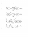
Figura 1é um desenho esquemático de um processo parapurificação de gás de escape de acordo com tecnologia conhecida.Figure 1 is a schematic drawing of an exhaust gas purification process according to known technology.
Figura 2é um desenho esquemático de um processo parapurificação de gás de escape de acordo com uma forma de realização preferidado processo da invenção.Figure 2 is a schematic drawing of an exhaust gas purification process according to a preferred embodiment of the invention.
Figura 3é um desenho esquemático de um processo parapurificação de gás de escape de acordo com outra forma de realização preferidado processo da invenção.Figure 3 is a schematic drawing of an exhaust gas purification process according to another preferred embodiment of the invention.
Figura 4é um desenho esquemático de um processo parapurificação de gás de escape de acordo com ainda outra forma de realizaçãopreferida do processo da invenção.Figure 4 is a schematic drawing of an exhaust gas purification process according to yet another preferred embodiment of the process of the invention.
Motores a diesel operam com ar em excesso e seus gases de escapecompreendem óxido de nitrogênio, NOX, monóxido de carbono, CO, matéria 510152025particulada e hidrocarbonetos incompletamente queimados, todosimplementando riscos à saúde.Diesel engines operate with excess air and their exhaust gases comprise nitrogen oxide, NOX, carbon monoxide, CO, particulate matter 510152025 and incompletely burned hydrocarbons, all implementing health risks.
A invenção basicamente compreende três processos durantepurificação normal de gás de escape:Oxidação catalítica, ondeCO, NO e HC reagem com O2para formar CO2, NO2 e H2O e/calor.The invention basically comprises three processes during normal exhaust gas purification: Catalytic oxidation, whereCO, NO and HC react with O2 to form CO2, NO2 and H2O and / heat.
Redução catalítica seletiva,onde NO e NO2 são tipicamente reduzidos por NH3 para formar N2e H2Oe captura das partículas em um filtro cataliticamente revestido, ondeCO, C, HC, e possível combinação de NH3 são oxidados em N2,CO2 e H2OC refere-se aqui à matéria particulada ou fuligem depositada sobreo filtro de particulados de diesel.Selective catalytic reduction, where NO and NO2 are typically reduced by NH3 to form N2e H2Oe capture the particles in a catalytically coated filter, whereCO, C, HC, and possible combination of NH3 are oxidized to N2, CO2 and H2OC refers to the particulate matter or soot deposited on the diesel particulate filter.
No entanto, quando as partículas são acumuladas sobre o filtro, ofiltro pode ser regenerado por oxidação com dióxido de nitrogênio, óxido demetal de base do revestimento de filtro ou em maiores temperaturas comoxigênio no gás de escape:C e HC são oxidados por NO, NO2 e/ou O2 para formar N2 , CO2 eH2O.However, when particles are accumulated on the filter, the filter can be regenerated by oxidation with nitrogen dioxide, base metal oxide of the filter liner or at higher temperatures as oxygen in the exhaust gas: C and HC are oxidized by NO, NO2 and / or O2 to form N2, CO2 and H2O.
A tecnologia de sistema de escape de diesel atualmente usada(tecnologia conhecida) é caracterizada pelo fato de ter um filtro catalisado ajusante com catalisador SCR, como mostrado em Figura 1.The currently used diesel exhaust system technology (known technology) is characterized by the fact that it has an adjunct catalytic filter with SCR catalyst, as shown in Figure 1.
Gás de escape 1 escoa de um motor para um catalisador deoxidação 2, o gás de escape oxidado 3 é então passado para filtro departiculados de diesel 4. Após esse agente redutor 5 ser injetado no gás deescape, o gás de escape misturado 6 é então introduzido em um catalisador 7 510152025para redução catalítica seletiva, SCR, de onde o gás de escape 8 sai docatalisador 7 limpo. Quando temperaturas aumentadas são necessárias,hidrocarboneto 9 é pós-injetado no motor ou injetado no gás de escape 1 entreo motor e catalisador de oxidação 2. Isto é ainda descrito em processo (1)abaixo.(1)Motor —* DOC—>cDPF —*Uréiainj —>zSCRem que DOC é um catalisador de oxidação de diesel contendo Pt para formaçãode NO2 , e cDPF é um filtro de fuligem catalisado que também pode conter Ptpara formação de NO2.Exhaust gas 1 drains from an engine to a
Uréiainj é injetada no agente redutor, tipicamente uma soluçãoaquosa de uréia, zSCR é um catalisador SCR de base zeolítica ou uma misturade óxido de metal de base ácida funcionalizado.Ureainj is injected into the reducing agent, typically an aqueous solution of urea, zSCR is a zeolytic-based SCR catalyst or a functionalized acid-base metal oxide mixture.
Durante a regeneração forçada do filtro com temperaturas deentrada de filtro em tomo de 600°C o sistema será como(2)Motor -> HCinj—> DOC^cDPF ->zSCRem que HCmj é hidrocarboneto, que é injetado em gás de escape a partir domotor e a montante de DOC.During forced filter regeneration with filter inlet temperatures around 600 ° C the system will be like (2) Engine -> HCinj—> DOC ^ cDPF -> zSCRem that HCmj is hydrocarbon, which is injected in exhaust gas from domotor and upstream of DOC.
Regeneração passiva de fuligem com NO2 ocorre na configuraçãocomo mostrada em processo (1).Passive soot regeneration with NO2 occurs in the configuration as shown in process (1).
O sistema tem várias desvantagens. O aquecimento e o início dareação de SCR a partir da partida a frio são lentos, e a emissão de NOX total,também medida em um ciclo de teste, será elevada. A partida é também lenta,como a injeção de uréia requer um mínimo de 200°C. Além disso, o catalisadorzSCR deve ser apto a suportar as temperaturas de regeneração de filtro de pelomenos 750°C, e também operação com zSCR normalmente requer razão deNO2/NO controlada, que é perturbada pelo cDPF conforme matéria particuladatambém reage com NO2 em filtro. Finalmente, o sistema é muito caro.The system has several disadvantages. The warm-up and start of SCR starting from the cold start is slow, and the total NOX emission, also measured in a test cycle, will be high. Starting is also slow, as the injection of urea requires a minimum of 200 ° C. In addition, the zSCR catalyst must be able to withstand the filter regeneration temperatures of at least 750 ° C, and also operation with zSCR usually requires a controlled NO2 / NO ratio, which is disturbed by the cDPF as particulate matter also reacts with NO2 in the filter. Finally, the system is very expensive.
Uma forma de realização preferida de presente invenção émostrada em Figura 2. Gás de escape 1 de um motor é passado através de umcatalisador de oxidação 2, um catalisador 7 para redução catalítica seletiva ecomo última etapa através de um filtro de particulados de diesel 4. Agenteredutor 5 é injetado entre catalisador de oxidação 2 e o catalisador de SCR 7.Hidrocarboneto 9 pode ser injetado a montante de catalisador de oxidação 2.O novo sistema de escape de diesel com a configuração reversa,SCR na frente de cDPF, é ainda descrito em processo (3) abaixo. Ele aindacompreende uma nova gestão especial.(3)Motor —> DOC—*Uréiair!j —>zSCR—> cDPFem que zSCR é um catalisador de SCR à base de zeólito ou um catalisador demistura de óxido de metal de base ácida funcionalizado, que tolera no mínimo750°C.cDPF é um filtro de particulados de diesel preferivelmentecataliticamente revestido. Nessa forma de realização é especialmente vantajosousar um revestimento de óxido de metal de base de paládio como o catalisadorBMC-211 comercialmente disponível de Haldor Top soe A/S e descrito nopedido de patente EP 1 916 029 . Esse catalisador limita possível emissão deNO2 e facilita a queima de fuligem na faixa de temperatura 300 - 600°C.DOC é um catalisador de oxidação de diesel, que pode terdiferentes composições. Este catalisador é metal(ais) precioso(s) sobrecarreadores de óxido de metal promovidos que tipicamente é aplicado emsubstratos de esqueletos monolíticos como cordierita, carboneto de silício,mulita ou Fecralloy. Ele contém tipicamente platina. Ele compreende platina epaládio sobre óxido de alumínio promovido por óxido de lantânio, ou platina epaládio sobre óxido de titânio promovido por óxido de silício, ou platina epaládio sobre óxido de cério promovido por óxido de zircônio.A preferred embodiment of the present invention is shown in Figure 2. Exhaust gas 1 from an engine is passed through an
A invenção irá assegurar a regeneração de fuligem do filtroefetivamente tanto para as condições passivas como ativas em sistemas de 510152025escape de diesel, onde o catalisador de SCR é colocado a montante de cDPF.Ela ainda assegura uma elevada conversão de NOX em partida a frio. A queimade fuligem com O2 no gás de escape ocorre na faixa de temperatura acima de575°C durante regeneração ativa. Regeneração passiva de NO2, que é queimade fuligem usando NO2, pode ocorrer na faixa de temperatura de 250 a 450°C.Finalmente, a queima de fuligem com catalisador passivo também pode ocorrerem um filtro catalisado. No intervalo de temperatura de 300 - 600°C, umcatalisador BMC-211 de metal de base pode facilitar a queima de fuligem.Uma regeneração ativa em sistema (3) ocorre a uma temperaturade entrada de filtro de cerca de 620°C com pós-injeção de diesel no motorsimultaneamente parando a injeção de uréia como mostrado em processo (4)abaixo. Nesse sistema é requerido que o catalisador de SCR por exemplocatalisador de SCR zeolítico possa suportar a temperatura(4)Motor—* HCinj—* DOC^zSCR-^cDPF Tfiltroin = 620°Cdurante 10 minutos.The invention will ensure the soot regeneration of the filter effectively for both passive and active conditions in 510152025 diesel exhaust systems, where the SCR catalyst is placed upstream of cDPF. It also ensures a high conversion of NOX in cold start. Soot burning with O2 in the exhaust gas occurs in the temperature range above 575 ° C during active regeneration. Passive regeneration of NO2, which is soot-burning using NO2, can occur in the temperature range of 250 to 450 ° C. Finally, soot-burning with passive catalyst can also occur a catalyzed filter. In the temperature range of 300 - 600 ° C, a base metal BMC-211 catalyst can facilitate soot burning. An active regeneration in system (3) occurs at a filter inlet temperature of about 620 ° C with post- diesel injection into the motors simultaneously stopping the urea injection as shown in process (4) below. In this system it is required that the SCR catalyst per example zeolitic SCR catalyst can withstand the temperature (4) Engine— * HCinj— * DOC ^ zSCR- ^ cDPF Tfiltroin = 620 ° C for 10 minutes.
Processo (3) tem várias vantagens em comparação com a presentetecnologia, mas parece ter uma desvantagem durante a regeneração passiva defiltro por dióxido de nitrogênio. A presente invenção resolve esse problemaaparente de sistema (3) de concentração de NO2 muito baixa a jusante do SCRcomparado com o sistema com um filtro catalisado a jusante com catalisador deSCR, como mostrado em processo (1) de tecnologia conhecida. A presenteinvenção assegura a regeneração passiva do filtro de fuligem com NO2.A presente invenção também envolve o controle ativo do sistema(3) ou (4). A invenção compreende que a concentração de NO2 étemporariamente aumentada em intervalos de tempo curtos parando a injeçãode uréia, assim NO2 é formado para a regeneração passiva e combustível dieselpode ser economizado. Esse aumento temporário de NO2 é iniciado quando aqueda de pressão através do filtro catalisado aumentou para um valor pré- 510152025ajustado, e a temperatura de entrada no filtro alcançou um valor pré-ajustado,que deve ser de pelo menos 250°C. Então, o sistema (3) funcionará comomostrado em processo de sistema (5)(5)Motor -> DOC—>zSCR—*cDPFNa faixa de temperatura de cerca de 300 - 400 °C, o NO2/NO seráótimo para um teor elevado de NO2. A concentração de NO2 e o efeito dequeima passiva de fuligem podem ser ainda aumentados por fechamentotemporário para a recirculação do gás de escape de motor (EGR), comomostrado abaixo por (6) concorrentemente com a injeção de uréia sendoparada, como mostrado em (5).(6)Motor (sem EGR) DOC->zSCR-^cDPFOutra melhoria de sistema (3) pode ser obtida por injeção deamónia (NH3) em vez de uréia, que requer calor tanto para a evaporação deágua como para a decomposição de uréia. Então, a reação de SCR pode iniciarde cerca de 150°C e o catalisador de SCR pode ser colocado muito mais pertodo catalisador de oxidação de diesel DOC como a mistura de NH3 pode ocorrerdentro de um comprimento de cano de escape de alguns centímetros, porexemplo 5 cm.Process (3) has several advantages compared to present technology, but it appears to have a disadvantage during passive regeneration of the nitrogen dioxide filter. The present invention solves this problem apparent from the system (3) of very low NO2 concentration downstream of the SCR compared to the system with a catalyzed filter downstream with the SCR catalyst, as shown in process (1) of known technology. The present invention ensures the passive regeneration of the soot filter with NO2. The present invention also involves the active control of the system (3) or (4). The invention understands that the NO2 concentration is temporarily increased in short time intervals by stopping the urea injection, so NO2 is formed for passive regeneration and diesel fuel can be saved. This temporary increase in NO2 is initiated when the pressure drop through the catalytic filter has increased to a pre-set value of 510152025, and the inlet temperature in the filter has reached a pre-set value, which must be at least 250 ° C. Then, the system (3) will work as shown in the system process (5) (5) Engine -> DOC—> zSCR— * cDPF In the temperature range of about 300 - 400 ° C, NO2 / NO will be great for a high content of NO2. The NO2 concentration and the passive soot-burning effect can be further increased by temporary closure for the recirculation of the engine exhaust gas (EGR), as shown below by (6) concurrently with the injection of stopped urea, as shown in (5) (6) Engine (without EGR) DOC-> zSCR- ^ cDPF Another system improvement (3) can be achieved by injecting ammonia (NH3) instead of urea, which requires heat for both water evaporation and urea decomposition. . Then, the SCR reaction can start from about 150 ° C and the SCR catalyst can be placed much closer to the DOC diesel oxidation catalyst as the NH3 mixture can occur within an exhaust pipe length of a few centimeters, for example 5 cm.
Uma menor saída de NOX do sistema de escape é então obtida naestrada e quando testada por qualquer ciclo de teste padrão governamental.O sistema com regeneração passiva melhorada por injeção deNH3 parada é mostrada por processos (5) e (6).Outra possível melhoria de sistema (5) consiste em injetar amónia(NH3) a montante do DOC. Assim, este NO2 extra é formado no DOC e éusado para regeneração passiva. Ao mesmo tempo, a temperatura no sistema éaumentada. Isso é mostrado abaixo com relação a com e sem reciclo de gás deescape.(7)Motor—> NH3inj—> DOC^zSCR^cDPF 510152025(8)Motor (sem EGR)-> NH3inj-> DOC-*zSCR-^cDPFO sistema (3) tem interesse especial para carros de passageiroscom opções de pós-injeção de diesel.A lower NOX output from the exhaust system is then obtained on the road and when tested by any government standard test cycle. The system with improved passive regeneration by stopped NH3 injection is shown by processes (5) and (6). system (5) consists of injecting ammonia (NH3) upstream of the DOC. Thus, this extra NO2 is formed in the DOC and is used for passive regeneration. At the same time, the temperature in the system is increased. This is shown below with and without exhaust gas recycling. (7) Engine—> NH3inj—> DOC ^ zSCR ^ cDPF 510152025 (8) Engine (without EGR) -> NH3inj-> DOC- * zSCR- ^ cDPFO system (3) is of special interest to passenger cars with diesel post-injection options.
Outra forma de realização preferida da invenção é mostrada emFigura 3, onde é mostrado que gás de escape 1 do motor passa sucessivamentepor um primeiro catalisador de oxidação 2, catalisador de redução seletiva 7,um segundo catalisador de oxidação 10 e finalmente o filtro de particulados dediesel 4. Hidrocarbonetos 9 e 11 podem ser adicionados à corrente de gás deescape a montante do primeiro 2 e do segundo 10 catalisadores de oxidação,enquanto agente redutor 5 é injetado na entrada do catalisador de reduçãoseletiva 7. Para fora do filtro 4 flui a corrente de gás de escape limpa 8.Uma quantidade de agente redutor 5 é controlada por válvula 12.Esta irá receber um sinal de, por exemplo, uma medição de diferença depressão através do filtro 4, e a válvula 12 irá se aproximar a fim de iniciar aregeneração passiva. Similarmente, quando uma necessidade de aumentar atemperatura dentro ou fora de um dos catalisadores de oxidação 2, 10, asválvulas 16 e/ou 14 serão abertas. Opcionalmente amónia deve ser adicionadaaqui. Essa forma de realização é ainda descrita abaixo. A operação normal édescrita por(9)Motor - DOC (1) -+Uréiainj ->SCR-+ HCinj-> DOC (2 )->cDPF.Esse é um exemplo importante e chamado sistema padrão reversode Haldor Top soe - sistema Euro VI. SCR pode ser ou SCR à base de vanádioou SCR zeolítico ou uma mistura de óxido de metal de base ácidafuncionalizado. Durante a regeneração ativa o processo é(10)Motor—> DOC (l)-*NH3inj -»zSCR-+ HCinj-> DOC (2 )-►cDPFE em partida a frio e com regeneração ativa simultânea 510152025(11)Motor—» NH3inj^ DOC (l)-*NH3inj -*zSCR-+ HCinj^DOC (2 )-> cDPF.Another preferred embodiment of the invention is shown in Figure 3, where it is shown that the engine's exhaust gas 1 passes successively through a
Por injeção de NH3 para a primeira partida a frio de DOC (1) amontante, o desempenho pode ser melhorado pelo calor gerado, e a razãoNO2/NO será melhor para a reação de SCR em zSCR também.O DOC (1) é o DOC descrito para sistema (3) .O catalisador de DOC (2) é de metal precioso sobre carreadores deóxido de metal promovidos que tipicamente é aplicado em substratos deesqueleto monolítico como cordierita, carboneto de silício, mulita ou Fecralloy.Esse catalisador também pode ser uma mistura de óxidos de metal de base comou sem metais preciosos que tipicamente é aplicado em substratos de esqueletomonolítico como cordierita, carboneto de silício, mulita ou Fecralloy. Ele nãocontém tipicamente platina. Ele compreende paládio sobre óxido de alumíniopromovido por óxido de lantânio, ou óxido de paládio sobre óxido de titâniopromovido por silício, ou paládio sobre óxido de cério promovido por óxido dezircônio, ou mistura de óxidos de cobre ou de manganês ou paládio sobre umamistura de óxidos de cobre ou de manganês.By injection of NH3 for the first cold start of DOC (1) upstream, performance can be improved by the heat generated, and the NO2 / NO ratio will be better for the SCR reaction in zSCR as well. DOC (1) is DOC described for system (3). The DOC catalyst (2) is a precious metal on advanced metal oxide carriers that is typically applied to monolithic skeleton substrates such as cordierite, silicon carbide, mullite or Fecralloy. This catalyst can also be a mixture of base metal oxides or without precious metals that is typically applied to skeletomonolytic substrates such as cordierite, silicon carbide, mullite or Fecralloy. It does not typically contain platinum. It comprises palladium on aluminum oxide promoted by lanthanum oxide, or palladium oxide on titanium oxide by silicon, or palladium on cerium oxide promoted by dezirium oxide, or a mixture of copper or manganese oxides or palladium on a mixture of oxides of oxides copper or manganese.
Sistema (9) é vantajoso para ambas as aplicações em caminhões eem carros de passeio. Uma terceira forma de realização é mostrada em Figura4. Aqui o gás de escape 1 do motor é passado através de redução catalíticaseletiva 7, oxidação catalítica 10 e finalmente através de filtro 4. Agenteredutor 5 é adicionado ao gás de escape 1 e hidrocarboneto 11 pode seradicionado entre redução catalítica seletiva 7 e oxidação catalítica 10.A vantagem com esse sistema de escape é que a temperatura deentrada máxima para o catalisador SCR pode ser a mesma que a temperatura desaída de motor, que é aproximadamente 550°C. Esse sistema irá facilitar queum catalisador SCR (V-SCR) à base de vanádio padrão possa ser selecionado.Por uso de V-SCR o processo será 510152025(12)Motor—» Uréiainj -^V-SCR-> HCinj->DOC-» cDPFOs catalisadores SCR de zeólito à base de cobre, Cu-zSCR, podemser usados como o catalisador dSCR selecionado como é menos dependentesobre a razão de NO2/NO, mas requer um tipo Cu-zSCR, que tolera emissão deHC do motor.System (9) is advantageous for both truck and passenger car applications. A third embodiment is shown in Figure 4. Here the engine exhaust gas 1 is passed through
O sistema com injeção de NH3 em vez de uréia para reação deSCR e com regeneração ativa simultânea será como(13)Motor—» NH3inj -^V-SCR-» HCinj^ DOC-» cDPFEm sistema (13) a distância a partir do coletor do motor para ocatalisador V-SCR pode ser diminuída por um fator de 10, de 50 cm a 5 cm.Assim, em motor de partida a frio, calor não é usado para aquecer as extensõessupérfluas de canos, mas para iniciar as reações químicas. O sistema (13)durante regeneração passiva controlada, onde a injeção de NH3 é parada,temporariamente será(14)Motor —»V-SCR—» DOC-* cDPFe equivalente sem EGR.(15)Motor (sem EGR) -^V-SCR-^ DOC-+ cDPFSistema (12) tem interesse especial para aplicações em caminhão.The system with NH3 injection instead of urea for SCR reaction and with simultaneous active regeneration will be like (13) Engine— »NH3inj - ^ V-SCR-» HCinj ^ DOC- »cDPFEm system (13) at a distance from the collector of the engine for the V-SCR catalyst can be reduced by a factor of 10, from 50 cm to 5 cm. Thus, in a cold starter, heat is not used to heat the superfluous pipe extensions, but to initiate chemical reactions. The system (13) during controlled passive regeneration, where the NH3 injection is stopped, will temporarily be (14) Engine - »V-SCR—» DOC- * cDPFe equivalent without EGR. (15) Engine (without EGR) - ^ V -SCR- ^ DOC- + cDPFSistema (12) is of special interest for truck applications.
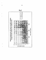
Experimentos de banco de teste de motor em um motor Scania de12 litros com um sistema SCR+DOC+cDPF dá uma queda de pressão de cargade fuligem não mudada após 7 ciclos de testes harmonizados mundiais comdosagem intermitente de uréia e teor de NO2 temporariamente elevado.A medição de queda de pressão sobre cDPF para o Io e 7o ciclosrepetidos de testes harmonizados mundiais (WHTC) foi em um dia onde osistema foi administrado tanto com dosagens baixas como elevadas de uréia.Em Figura 5, as duas curvas são idênticas, consequentemente elasestão escritas uma no topo da outra. Isso significa que nenhum aumento de queda de pressão a partir da carga de fuligem adicional é visto. Este resultado deve ser comparado para o exemplo de referência abaixo.Nesse exemplo de referência, a dosagem de uréia é contínua e elevada para reação de SCR alta. Isso permite saídas baixas de NO2 e NOx5 (aproximadamente 1-2 g NOx/kWh) do catalisador SCR - entrada cDPF) . Na Figura 6, nota-se, em contraste com a Figura 5 acima, aumentos da queda de pressão a partir do primeiro WHTC até o 7o ciclo. Isso significa que a fuligem está se acumulando no filtro.Engine test bench experiments on a 12-liter Scania engine with a SCR + DOC + cDPF system give an unchanged soot load pressure after 7 globally harmonized test cycles with intermittent urea dosing and temporarily high NO2 content. pressure drop measurement over cDPF for the 1st and 7th cycles of repeated worldwide harmonized tests (WHTC) was on a day where the system was administered with both low and high dosages of urea. In Figure 5, the two curves are identical, hence they are written one on top of the other. This means that no increase in pressure drop from the additional soot load is seen. This result should be compared to the reference example below. In this reference example, the dosage of urea is continuous and high for high SCR reaction. This allows for low NO2 and NOx5 outputs (approximately 1-2 g NOx / kWh) from the SCR catalyst - cDPF input). In Figure 6, it can be seen, in contrast to Figure 5 above, increases in pressure drop from the first WHTC to the 7th cycle. This means that soot is accumulating in the filter.
Claims (13)
Applications Claiming Priority (3)
| Application Number | Priority Date | Filing Date | Title |
|---|---|---|---|
| DKPA20090023620 | 2009-02-20 | ||
| DKPA200900236 | 2009-02-20 | ||
| PCT/EP2009/009017 WO2010094313A1 (en) | 2009-02-20 | 2009-12-16 | Method for purification of exhaust gas from a diesel engine |
Publications (2)
| Publication Number | Publication Date |
|---|---|
| BRPI0924120A2 BRPI0924120A2 (en) | 2016-10-25 |
| BRPI0924120B1 true BRPI0924120B1 (en) | 2020-11-17 |
Family
ID=42077443
Family Applications (1)
| Application Number | Title | Priority Date | Filing Date |
|---|---|---|---|
| BRPI0924120-5A BRPI0924120B1 (en) | 2009-02-20 | 2009-12-16 | method for purifying exhaust gas from a diesel engine in a system |
Country Status (11)
| Country | Link |
|---|---|
| US (1) | US8997465B2 (en) |
| EP (1) | EP2399011B1 (en) |
| JP (1) | JP5757574B2 (en) |
| KR (1) | KR101699923B1 (en) |
| CN (2) | CN102325971A (en) |
| BR (1) | BRPI0924120B1 (en) |
| CA (1) | CA2750013C (en) |
| ES (1) | ES2414160T3 (en) |
| PL (1) | PL2399011T3 (en) |
| RU (1) | RU2524165C2 (en) |
| WO (1) | WO2010094313A1 (en) |
Families Citing this family (41)
| Publication number | Priority date | Publication date | Assignee | Title |
|---|---|---|---|---|
| FR2956039B1 (en) * | 2010-02-08 | 2014-08-29 | Peugeot Citroen Automobiles Sa | PROCESS FOR TREATING EXHAUST GAS CONTAINING NITROGEN OXIDES |
| US9528413B2 (en) * | 2010-07-30 | 2016-12-27 | Ford Global Technologies, Llc | Synergistic SCR/DOC configurations for lowering diesel emissions |
| US8479500B2 (en) * | 2011-04-08 | 2013-07-09 | GM Global Technology Operations LLC | Exhaust treatment system for an internal combustion engine |
| KR101251463B1 (en) * | 2011-04-14 | 2013-04-04 | 한국기계연구원 | Apparatus and method for purifying exhaust gas |
| US8629781B2 (en) * | 2011-05-05 | 2014-01-14 | GM Global Technology Operations LLC | Efficiency determination for a selective-catalytic-reduction catalyst |
| DE102011100677A1 (en) * | 2011-05-06 | 2012-11-08 | Daimler Ag | Operating method for a motor vehicle diesel engine |
| LT2597279T (en) * | 2011-11-22 | 2021-12-10 | Deutz Aktiengesellschaft | Method and device for cleaning diesel engine exhaust gases |
| WO2013095214A1 (en) * | 2011-12-23 | 2013-06-27 | Volvo Lastvagnar Ab | Exhaust aftertreatment system and method for operating the system |
| US8997461B2 (en) | 2012-05-21 | 2015-04-07 | Cummins Emission Solutions Inc. | Aftertreatment system having two SCR catalysts |
| DE112014000618T5 (en) | 2013-02-18 | 2015-10-22 | Cummins, Inc. | System, method and apparatus for managing the post-treatment temperature |
| WO2015031611A1 (en) * | 2013-08-28 | 2015-03-05 | Johnson Matthey Plc | Co slip catalyst and method of using |
| DE102015000955A1 (en) | 2014-01-20 | 2015-07-23 | Cummins Inc. | Systems and methods for reducing NOx and HC emissions |
| US9512761B2 (en) | 2014-02-28 | 2016-12-06 | Cummins Inc. | Systems and methods for NOx reduction and aftertreatment control using passive NOx adsorption |
| US9567888B2 (en) | 2014-03-27 | 2017-02-14 | Cummins Inc. | Systems and methods to reduce reductant consumption in exhaust aftertreament systems |
| CN207363741U (en) | 2014-06-30 | 2018-05-15 | 优美科两合公司 | Exhaust after treatment system for diesel engine |
| WO2016024126A1 (en) * | 2014-08-15 | 2016-02-18 | Johnson Matthey Public Limited Company | Zoned catalyst for treating exhaust gas |
| KR101628098B1 (en) * | 2014-11-03 | 2016-06-08 | 현대자동차 주식회사 | Exhaust gas purification system for vehicle |
| CN105709861B (en) * | 2014-12-05 | 2018-07-03 | 中国石油化工股份有限公司 | A kind of regeneration method of SCR denitration |
| GB2531368B (en) * | 2015-02-11 | 2017-02-01 | Ford Global Tech Llc | A method for emissions regulation |
| CA2983207C (en) | 2015-04-21 | 2021-08-31 | Haldor Topsoe A/S | A process for the removal of soot from a sulfurous gas stream |
| GB2564333B (en) * | 2015-06-28 | 2019-12-04 | Johnson Matthey Plc | Catalytic wall-flow filter having a membrane |
| CN107787246A (en) * | 2015-07-03 | 2018-03-09 | 托普索公司 | For the temperature controlled method and system in catalytic oxidation |
| SE539134C2 (en) * | 2015-08-27 | 2017-04-11 | Scania Cv Ab | Exhaust gas treatment system and method for treating an exhaust gas stream |
| SE539131C2 (en) * | 2015-08-27 | 2017-04-11 | Scania Cv Ab | Process and exhaust treatment system for treating an exhaust stream |
| GB201517579D0 (en) * | 2015-10-06 | 2015-11-18 | Johnson Matthey Plc | Passive nox adsorber |
| GB201517578D0 (en) | 2015-10-06 | 2015-11-18 | Johnson Matthey Plc | Passive nox adsorber |
| FR3043430B1 (en) * | 2015-11-09 | 2019-08-09 | Psa Automobiles Sa. | DEVICE FOR POST-PROCESSING EXHAUST GASES OF A THERMAL ENGINE |
| WO2018025827A1 (en) * | 2016-08-04 | 2018-02-08 | エヌ・イーケムキャット株式会社 | Cold start-compatible urea scr system |
| US10337959B2 (en) * | 2016-09-01 | 2019-07-02 | Ford Global Technologies, Llc | System, method and apparatus for making evident diesel exhaust fluid contamination |
| US10598061B2 (en) * | 2017-03-22 | 2020-03-24 | Ford Global Technologies, Llc | Methods and systems for a diesel oxidation catalyst |
| US10392980B2 (en) * | 2017-03-22 | 2019-08-27 | Ford Global Technologies, Llc | Methods and systems for a diesel oxidation catalyst |
| KR102301890B1 (en) * | 2017-04-03 | 2021-09-13 | 현대자동차주식회사 | Method for controlling the regeneration of scr on diesel particular filter |
| CN107237663A (en) * | 2017-07-19 | 2017-10-10 | 无锡威孚高科技集团股份有限公司 | One kind is used for the double vaporation-type dpf regeneration systems of Light-duty Vehicle |
| JP2019035360A (en) * | 2017-08-14 | 2019-03-07 | いすゞ自動車株式会社 | Exhaust emission control system |
| RU2705354C1 (en) * | 2019-01-14 | 2019-11-06 | Кирилл Николаевич Войнов | Exhaust gas catching and cleaning method |
| US11015502B2 (en) * | 2019-04-18 | 2021-05-25 | Caterpillar Inc. | Thermal management lightoff assist systems and methods for regenerating oxidation catalyst in exhaust system |
| US11779906B2 (en) * | 2019-04-29 | 2023-10-10 | Basf Corporation | Exhaust gas treatment system for ultra low NOx and cold start |
| US11421572B2 (en) * | 2020-01-09 | 2022-08-23 | Cummins Inc. | Exhaust gas aftertreatment system with a selective catalytic reduction catalyst member upstream of a particulate filter |
| CN115697532A (en) * | 2020-06-12 | 2023-02-03 | 巴斯夫公司 | Exhaust gas treatment system comprising a multifunctional catalyst |
| US11927124B2 (en) | 2021-11-30 | 2024-03-12 | Cummins Power Generation Inc. | Aftertreatment system, dual fuel system, and methods therefor |
| US11519315B1 (en) | 2021-11-30 | 2022-12-06 | Cummins Power Generation Inc. | Aftertreatment system, dual fuel system, and dual fuel apparatus |
Family Cites Families (27)
| Publication number | Priority date | Publication date | Assignee | Title |
|---|---|---|---|---|
| GB9913331D0 (en) * | 1999-06-09 | 1999-08-11 | Johnson Matthey Plc | Treatment of exhaust gas |
| JP2003049637A (en) * | 2001-08-02 | 2003-02-21 | Toyota Industries Corp | Exhaust emission control device for engine |
| DE10243270A1 (en) * | 2002-09-18 | 2004-03-25 | Robert Bosch Gmbh | Exhaust gas purification unit used in diesel and gasoline direct injection engines has a switching device for introducing a reducing agent into the exhaust gas stream arranged before or within an oxidation catalyst |
| US6928806B2 (en) * | 2002-11-21 | 2005-08-16 | Ford Global Technologies, Llc | Exhaust gas aftertreatment systems |
| US6947831B2 (en) * | 2003-04-11 | 2005-09-20 | Ford Global Technologies, Llc | Pressure sensor diagnosis via a computer |
| US7229597B2 (en) * | 2003-08-05 | 2007-06-12 | Basfd Catalysts Llc | Catalyzed SCR filter and emission treatment system |
| DE102004049289B4 (en) * | 2004-10-09 | 2018-02-15 | Robert Bosch Gmbh | Exhaust after-treatment system and exhaust aftertreatment method for an internal combustion engine |
| WO2006066043A1 (en) * | 2004-12-15 | 2006-06-22 | Donaldson Company, Inc. | Control for an engine exhaust treatment system |
| JP2006274986A (en) * | 2005-03-30 | 2006-10-12 | Mitsubishi Fuso Truck & Bus Corp | Exhaust gas aftertreatment device |
| DE102006022599B4 (en) * | 2006-05-15 | 2011-02-10 | Continental Automotive Gmbh | Method and device for operating an internal combustion engine |
| GB0617070D0 (en) * | 2006-08-30 | 2006-10-11 | Johnson Matthey Plc | Low Temperature Hydrocarbon SCR |
| US7591132B2 (en) * | 2006-09-20 | 2009-09-22 | Gm Global Technology Operations, Inc. | Apparatus and method to inject a reductant into an exhaust gas feedstream |
| KR100785156B1 (en) * | 2006-10-19 | 2007-12-11 | 현대자동차주식회사 | Exhaust gas reduction system for vehicle |
| JP5118331B2 (en) * | 2006-11-15 | 2013-01-16 | 三菱ふそうトラック・バス株式会社 | Exhaust purification device |
| US7709414B2 (en) * | 2006-11-27 | 2010-05-04 | Nanostellar, Inc. | Engine exhaust catalysts containing palladium-gold |
| US20080127638A1 (en) * | 2006-12-01 | 2008-06-05 | Marius Vaarkamp | Emission Treatment Systems and Methods |
| JP5196674B2 (en) * | 2007-01-17 | 2013-05-15 | ナノステラー インコーポレイテッド | Engine exhaust gas catalyst containing palladium-gold |
| JP4900002B2 (en) * | 2007-04-05 | 2012-03-21 | トヨタ自動車株式会社 | Exhaust gas purification system for internal combustion engine |
| JP4844467B2 (en) * | 2007-05-07 | 2011-12-28 | 日産自動車株式会社 | Exhaust gas purification device for internal combustion engine |
| JP2008286059A (en) * | 2007-05-16 | 2008-11-27 | Hino Motors Ltd | Exhaust emission treatment device |
| DE102007030234A1 (en) * | 2007-06-29 | 2009-01-02 | Ford Global Technologies, LLC, Dearborn | Exhaust gas treatment device for e.g. diesel engine, has nitrogen oxide storage component provided proximate to substrate of diesel particulate filter, and catalyst provided for selective catalytic reduction of nitrogen oxide in gas |
| EP2078834B1 (en) * | 2008-01-10 | 2014-06-04 | Haldor Topsoe A/S | Method and system for purification of exhaust gas from diesel engines |
| EP2112341B1 (en) * | 2008-04-22 | 2018-07-11 | Umicore AG & Co. KG | Method for purification of an exhaust gas from a diesel engine |
| DE102008039112A1 (en) * | 2008-08-21 | 2010-02-25 | Deutz Ag | aftertreatment system |
| JP2010180861A (en) * | 2009-02-09 | 2010-08-19 | Toyota Industries Corp | Exhaust emission control device |
| US8621854B2 (en) * | 2010-06-29 | 2014-01-07 | GM Global Technology Operations LLC | System and method for determining an age of and controlling a selective catalytic reduction catalyst |
| US20120144802A1 (en) * | 2010-12-10 | 2012-06-14 | Driscoll James J | Exhaust system having doc regeneration strategy |
-
2009
- 2009-12-16 CA CA2750013A patent/CA2750013C/en not_active Expired - Fee Related
- 2009-12-16 PL PL09795709T patent/PL2399011T3/en unknown
- 2009-12-16 US US13/147,418 patent/US8997465B2/en active Active
- 2009-12-16 RU RU2011138296/06A patent/RU2524165C2/en active
- 2009-12-16 EP EP09795709.6A patent/EP2399011B1/en active Active
- 2009-12-16 JP JP2011550424A patent/JP5757574B2/en active Active
- 2009-12-16 CN CN2009801571854A patent/CN102325971A/en active Pending
- 2009-12-16 KR KR1020117018700A patent/KR101699923B1/en active IP Right Grant
- 2009-12-16 ES ES09795709T patent/ES2414160T3/en active Active
- 2009-12-16 BR BRPI0924120-5A patent/BRPI0924120B1/en active IP Right Grant
- 2009-12-16 WO PCT/EP2009/009017 patent/WO2010094313A1/en active Application Filing
- 2009-12-16 CN CN201610083045.9A patent/CN105715329A/en active Pending
Also Published As
| Publication number | Publication date |
|---|---|
| US8997465B2 (en) | 2015-04-07 |
| CN102325971A (en) | 2012-01-18 |
| RU2011138296A (en) | 2013-03-27 |
| EP2399011A1 (en) | 2011-12-28 |
| KR20110116029A (en) | 2011-10-24 |
| WO2010094313A1 (en) | 2010-08-26 |
| RU2524165C2 (en) | 2014-07-27 |
| JP5757574B2 (en) | 2015-07-29 |
| CN105715329A (en) | 2016-06-29 |
| JP2012518734A (en) | 2012-08-16 |
| CA2750013C (en) | 2016-11-22 |
| PL2399011T3 (en) | 2013-09-30 |
| US20110283680A1 (en) | 2011-11-24 |
| BRPI0924120A2 (en) | 2016-10-25 |
| KR101699923B1 (en) | 2017-01-25 |
| ES2414160T3 (en) | 2013-07-18 |
| EP2399011B1 (en) | 2013-04-24 |
| CA2750013A1 (en) | 2010-08-26 |
Similar Documents
| Publication | Publication Date | Title |
|---|---|---|
| BRPI0924120B1 (en) | method for purifying exhaust gas from a diesel engine in a system | |
| US8920756B2 (en) | Silver promoted close-coupled NOx absorber | |
| RU2504668C2 (en) | Exhaust system for ice running on lean mixes | |
| EP1458960B1 (en) | Improvements in selective catalytic reduction | |
| RU2517714C2 (en) | Method of removing impurities from diesel engine exhaust gas | |
| JP6074912B2 (en) | Exhaust gas purification system and exhaust gas purification method | |
| US20120247088A1 (en) | Exhaust gas after-treatment system | |
| BR112014013233B1 (en) | exhaust system for an internal combustion engine with a poor combustion | |
| BRPI1013401B1 (en) | filter to filter particulate matter, and discharge system for a compression ignition engine | |
| BR112014013261B1 (en) | exhaust system for a low-combustion internal combustion engine, and method to reduce or prevent a selective catalytic reduction catalyst | |
| BR112015008400B1 (en) | system for treating exhaust gases containing nox from an engine, and method for treating an exhaust gas stream from the engine containing nox and soot | |
| KR20110117323A (en) | Diesel engine exhaust gas purification device having ammonia decomposition module | |
| BR112013021254B1 (en) | exhaust system for a lean-burn vehicle internal combustion engine; and, lean-burn internal combustion engine | |
| CN207363741U (en) | Exhaust after treatment system for diesel engine | |
| US10279313B2 (en) | Method, multifunctional filter and system for the removal of particulate matter and noxious compounds from engine exhaust gas | |
| EP3205398A1 (en) | Method for preparing zeolite catalyst | |
| US20140134062A1 (en) | Exhaust gas purification system of vehicle | |
| CN106523088A (en) | Aftertreatment system for diesel vehicle | |
| Zhao et al. | Pollutant emission characteristics of the close-coupled selective catalytic reduction system for diesel engines under low exhaust temperature conditions | |
| US20180135485A1 (en) | SELECTIVE CATALYTIC REDUCTION FILTER DEVICES HAVING NOx STORAGE CAPABILITIES | |
| JP2020169640A (en) | Exhaust emission control system | |
| Wunsch et al. | Aftertreatment System for NOx and Soot Removal-Evaluation of an Integrated System | |
| Hou | Development of Spatially-Resolved FTIR–Gas Concentration Measurements inside a Monolith-Supported Selective Catalytic Reduction Catalyst |
Legal Events
| Date | Code | Title | Description |
|---|---|---|---|
| B25A | Requested transfer of rights approved |
Owner name: UMICORE AG AND CO. KG (DE) |
|
| B06F | Objections, documents and/or translations needed after an examination request according [chapter 6.6 patent gazette] | ||
| B06U | Preliminary requirement: requests with searches performed by other patent offices: procedure suspended [chapter 6.21 patent gazette] | ||
| B09A | Decision: intention to grant [chapter 9.1 patent gazette] | ||
| B16A | Patent or certificate of addition of invention granted [chapter 16.1 patent gazette] |
Free format text: PRAZO DE VALIDADE: 10 (DEZ) ANOS CONTADOS A PARTIR DE 17/11/2020, OBSERVADAS AS CONDICOES LEGAIS. |