BRPI0917618B1 - device with a respiratory interface, fluid coupling device for a device with a respiratory interface and exhalation mechanism for a device with a respiratory interface - Google Patents
device with a respiratory interface, fluid coupling device for a device with a respiratory interface and exhalation mechanism for a device with a respiratory interface Download PDFInfo
- Publication number
- BRPI0917618B1 BRPI0917618B1 BRPI0917618-7A BRPI0917618A BRPI0917618B1 BR PI0917618 B1 BRPI0917618 B1 BR PI0917618B1 BR PI0917618 A BRPI0917618 A BR PI0917618A BR PI0917618 B1 BRPI0917618 B1 BR PI0917618B1
- Authority
- BR
- Brazil
- Prior art keywords
- ventilation holes
- respiratory interface
- circumference
- exhalation
- ventilation
- Prior art date
Links
Images


Classifications
-
- A—HUMAN NECESSITIES
- A61—MEDICAL OR VETERINARY SCIENCE; HYGIENE
- A61M—DEVICES FOR INTRODUCING MEDIA INTO, OR ONTO, THE BODY; DEVICES FOR TRANSDUCING BODY MEDIA OR FOR TAKING MEDIA FROM THE BODY; DEVICES FOR PRODUCING OR ENDING SLEEP OR STUPOR
- A61M16/00—Devices for influencing the respiratory system of patients by gas treatment, e.g. ventilators; Tracheal tubes
- A61M16/20—Valves specially adapted to medical respiratory devices
- A61M16/208—Non-controlled one-way valves, e.g. exhalation, check, pop-off non-rebreathing valves
-
- A—HUMAN NECESSITIES
- A61—MEDICAL OR VETERINARY SCIENCE; HYGIENE
- A61M—DEVICES FOR INTRODUCING MEDIA INTO, OR ONTO, THE BODY; DEVICES FOR TRANSDUCING BODY MEDIA OR FOR TAKING MEDIA FROM THE BODY; DEVICES FOR PRODUCING OR ENDING SLEEP OR STUPOR
- A61M16/00—Devices for influencing the respiratory system of patients by gas treatment, e.g. ventilators; Tracheal tubes
- A61M16/06—Respiratory or anaesthetic masks
-
- A—HUMAN NECESSITIES
- A61—MEDICAL OR VETERINARY SCIENCE; HYGIENE
- A61M—DEVICES FOR INTRODUCING MEDIA INTO, OR ONTO, THE BODY; DEVICES FOR TRANSDUCING BODY MEDIA OR FOR TAKING MEDIA FROM THE BODY; DEVICES FOR PRODUCING OR ENDING SLEEP OR STUPOR
- A61M16/00—Devices for influencing the respiratory system of patients by gas treatment, e.g. ventilators; Tracheal tubes
- A61M16/08—Bellows; Connecting tubes ; Water traps; Patient circuits
- A61M16/0816—Joints or connectors
- A61M16/0825—Joints or connectors with ball-sockets
-
- A—HUMAN NECESSITIES
- A61—MEDICAL OR VETERINARY SCIENCE; HYGIENE
- A61M—DEVICES FOR INTRODUCING MEDIA INTO, OR ONTO, THE BODY; DEVICES FOR TRANSDUCING BODY MEDIA OR FOR TAKING MEDIA FROM THE BODY; DEVICES FOR PRODUCING OR ENDING SLEEP OR STUPOR
- A61M16/00—Devices for influencing the respiratory system of patients by gas treatment, e.g. ventilators; Tracheal tubes
- A61M16/20—Valves specially adapted to medical respiratory devices
-
- A—HUMAN NECESSITIES
- A61—MEDICAL OR VETERINARY SCIENCE; HYGIENE
- A61M—DEVICES FOR INTRODUCING MEDIA INTO, OR ONTO, THE BODY; DEVICES FOR TRANSDUCING BODY MEDIA OR FOR TAKING MEDIA FROM THE BODY; DEVICES FOR PRODUCING OR ENDING SLEEP OR STUPOR
- A61M16/00—Devices for influencing the respiratory system of patients by gas treatment, e.g. ventilators; Tracheal tubes
- A61M16/06—Respiratory or anaesthetic masks
- A61M16/0605—Means for improving the adaptation of the mask to the patient
- A61M16/0633—Means for improving the adaptation of the mask to the patient with forehead support
-
- A—HUMAN NECESSITIES
- A61—MEDICAL OR VETERINARY SCIENCE; HYGIENE
- A61M—DEVICES FOR INTRODUCING MEDIA INTO, OR ONTO, THE BODY; DEVICES FOR TRANSDUCING BODY MEDIA OR FOR TAKING MEDIA FROM THE BODY; DEVICES FOR PRODUCING OR ENDING SLEEP OR STUPOR
- A61M2205/00—General characteristics of the apparatus
- A61M2205/42—Reducing noise
Landscapes
- Health & Medical Sciences (AREA)
- Pulmonology (AREA)
- Heart & Thoracic Surgery (AREA)
- Engineering & Computer Science (AREA)
- Anesthesiology (AREA)
- Biomedical Technology (AREA)
- Emergency Medicine (AREA)
- Hematology (AREA)
- Life Sciences & Earth Sciences (AREA)
- Animal Behavior & Ethology (AREA)
- General Health & Medical Sciences (AREA)
- Public Health (AREA)
- Veterinary Medicine (AREA)
- Respiratory Apparatuses And Protective Means (AREA)
- Measurement Of The Respiration, Hearing Ability, Form, And Blood Characteristics Of Living Organisms (AREA)
Abstract
dispositivo com interface respiratória, dispositivo de acoplamento fluido para um dispositivo com interface respiratória e mecanismo de exalação para um dispositivo com interface respiratória trata-se de um dispositivo com interface respiratória que inclui um dispositivo de acoplamento fluido que tem um corpo principal e uma placa de exalação que tem uma pluralidade de furos para ventilação, cuja placa de exalação é separada de e acoplada ao corpo principal. a presente invenção refere-se adicionalmente a um dispositivo de acoplamento fluido que inclui uma porção de exaustão que tem uma pluralidade de furos para ventilação com um formato afunilado. um conjunto de furos para ventilação tem um ângulo incidente que irradia e se origina de um ponto comum. a presente invenção também se refere a um mecanismo de exalação que inclui uma pluralidade de furos para ventilação definidos por uma parede interna reta contínua que se estende de uma superfície interna a uma superfície externa em que uma circunferência externa do furo para ventilação é deslocada com respeito a uma circunferência interna.device with respiratory interface, fluid coupling device for a device with respiratory interface and exhalation mechanism for a device with respiratory interface it is a device with respiratory interface that includes a fluid coupling device that has a main body and a plate exhalation which has a plurality of ventilation holes, the exhalation plate of which is separated from and coupled to the main body. the present invention further relates to a fluid coupling device that includes an exhaust portion that has a plurality of tapered shaped ventilation holes. a set of ventilation holes has an incident angle that radiates and originates from a common point. the present invention also relates to an exhalation mechanism that includes a plurality of ventilation holes defined by a continuous straight inner wall that extends from an inner surface to an outer surface in which an outer circumference of the vent hole is displaced with respect to an inner circumference.
Description
O presente pedido de patente reivindica o benefício de prioridade sob 35 U.S.C. § 119(e) do Pedido de Patente Provisório Norte-americano 61/121.591 depositado em 11 de dezembro de 2008, cujo conteúdo é aqui incorporado a título de referência,This patent application claims priority benefit under 35 U.S.C. § 119 (e) of US Provisional Patent Application 61 / 121,591 filed on December 11, 2008, the contents of which are hereby incorporated by reference,
A presente invenção refere-se aos dispositivos com interface respiratória para transportar um gás de e/ou para uma via aérea de um usuário, e em particular, a um dispositivo com interface respiratória, tal como uma máscara, que inclui um dispositivo de acoplamento fluido que tem vários mecanismos aperfeiçoados de respiro de exaustão.The present invention relates to devices with a respiratory interface for transporting a gas from and / or into a user's airway, and in particular, a device with a respiratory interface, such as a mask, that includes a fluid coupling device which has several improved exhaust vent mechanisms.
Uma variedade de máscaras respiratórias é conhecida, as quais ficam em contato com as áreas que circundam o nariz e/ou a boca de um usuário humano. As utilizações para tais máscaras incluem a respiração em altitude elevada (aplicações em aviação), natação, mineração, combate a incêndios e várias aplicações diagnósticas e terapêuticas médicas.A variety of respiratory masks are known, which are in contact with the areas surrounding the nose and / or mouth of a human user. Uses for such masks include high altitude breathing (aviation applications), swimming, mining, fire fighting and various medical diagnostic and therapeutic applications.
Em muitas tais aplicações, um gás é provido a uma pressão positiva dentro da máscara para o consumo pelo usuário. O gás é tipicamente provido ao usuário através de uma entrada de ar, tal como uma abertura, provida na máscara. Além disso, a fim de facilitar a distribuição do gás na máscara, um dispositivo de acoplamento fluido, tal como um conduto de giro, é normalmente acoplado à abertura da entrada de ar da máscara. Especificamente, uma extremidade do dispositivo de acoplamento fluido é acoplada à entrada da máscara e uma outra extremidade do dispositivo de acoplamento fluido é acoplada, talvez através de um ou mais condutos adicionais, a uma fonte de gás externa, tal como uma respiro de um ventilador ou outro dispositivo apropriado.In many such applications, a gas is provided at a positive pressure within the mask for consumption by the user. The gas is typically supplied to the user through an air inlet, such as an opening, provided in the mask. In addition, in order to facilitate the distribution of gas in the mask, a fluid coupling device, such as a turning duct, is normally coupled to the opening of the mask air inlet. Specifically, one end of the fluid coupling device is coupled to the mask inlet and the other end of the fluid coupling device is coupled, perhaps through one or more additional conduits, to an external gas source, such as a ventilator vent. or other appropriate device.
As máscaras respiratórias também incluem frequentemente um mecanismo para remover o dióxido de carbono 5 gerado pelo usuário da máscara à atmosfera. Em um conjunto de mascara respiratória conhecido, o mecanismo de ventilação é provido no dispositivo de acoplamento fluido (por exemplo, um dispositivo de cotovelo) conectado à entrada de ar da máscara na forma de um número de furos para ventilação providosdiretamente no dispositivo de acoplamento fluido quando é manufaturado, como por meio de um molde ou um processo de montagem.Respiratory masks also often include a mechanism to remove the
Conforme será apreciado, o processo de manufatura particular que é empregado impõe limites sobre como os furos para ventilação podem ser formados. Por exemplo, em um processo de moldagem utilizado para formar um dispositivo de cotovelo, o formato e a configuração particular dos furos para ventilação são limitados pelo molde. Especificamente, devido a um ou mais cortes feitos por baixo, tipicamente incluídos no molde utilizado para a produção do dispositivo de cotovelo, pode ser difícil e pouco prático formar furos para ventilação no dispositivo de cotovelo que se afilam de um grande diâmetro na parte interna do dispositivo de cotovelo a um diâmetro menor na parte externa do dispositivo "25 de cotovelo.As will be appreciated, the particular manufacturing process that is employed imposes limits on how ventilation holes can be formed. For example, in a molding process used to form an elbow device, the particular shape and configuration of the ventilation holes is limited by the mold. Specifically, due to one or more cuts made from below, typically included in the mold used for the production of the elbow device, it can be difficult and impractical to form ventilation holes in the elbow device that taper from a large diameter in the inner part of the elbow. elbow device to a smaller diameter on the outside of the elbow device "25.
Os autores da presente invenção reconhecem que há espaço para o aperfeiçoamento na área de máscaras e de dispositivos de máscara respiratória similares, e, em particular, para a obtenção de um bom mecanismo de ventilação 3 0 para o esgotamento de gases tais como o dióxido de carbono gerado pelo usuário da máscara à atmosfera.The authors of the present invention recognize that there is room for improvement in the field of masks and similar respiratory mask devices, and, in particular, for obtaining a
Em uma realização, a invenção apresenta um dispositivo com interface respiratória que inclui um primeiroIn one embodiment, the invention features a device with a respiratory interface that includes a first
corpo principal e um dispositivo de acoplamento fluido. O dispositivo de acoplamento fluido ê acoplado de maneira operativa ao primeiro corpo principal. 0 dispositivo de acoplamento fluido tem um segundo corpo principal e uma placa de exalação. A placa de exalação inclui uma pluralidade de furos para ventilação. A placa de exalação é separada de e acoplada ao segundo corpo principal.main body and a fluid coupling device. The fluid coupling device is operatively coupled to the first main body. The fluid coupling device has a second main body and an exhalation plate. The exhalation plate includes a plurality of ventilation holes. The exhalation plate is separated from and attached to the second main body.
Em um aspecto, a invenção apresenta uma placa de exalação que inclui uma superfície interna e uma superfície externa, e cada um dos furos para ventilação têm uma circunferência interna na superfície interna e uma circunferência externa na superfície externa, e para cada furo para ventilação, a circunferência interna é maior do que a circunferência externa.In one aspect, the invention features an exhalation plate that includes an inner surface and an outer surface, and each of the ventilation holes has an inner circumference on the inner surface and an outer circumference on the outer surface, and for each hole for ventilation, the inner circumference is larger than the outer circumference.
Em outro aspecto, a invenção provê para que cada um dos furos para ventilação tenha um formato afunilado, que se afunila a partir de uma superfície interna da placa de exalação. Em um aspecto adicional, o formato afunilado é um formato geralmente cônico.In another aspect, the invention provides that each of the ventilation holes has a tapered shape, which tapers from an internal surface of the exhalation plate. In an additional aspect, the tapered shape is a generally tapered shape.
Em outro aspecto, a invenção apresenta uma placa de exalação acoplada de maneira removível ao segundo corpo principal.In another aspect, the invention features an exhalation plate removably coupled to the second main body.
Em outra realização, a invenção apresenta um dispositivo de acoplamento fluido para um dispositivo com interface respiratória. O dispositivo de acoplamento fluido inclui um corpo principal e uma porção de exaustão. A porção de exaustão tem uma pluralidade de furos para ventilação com um formato afunilado. Um primeiro conjunto de furos para ventilação tem um ângulo incidente associado que irradia e se origina de um ponto comum.In another embodiment, the invention features a fluid coupling device for a device with a respiratory interface. The fluid coupling device includes a main body and an exhaust portion. The exhaust portion has a plurality of tapered shaped ventilation holes. A first set of ventilation holes has an associated incident angle that radiates and originates from a common point.
Em aspectos alternativos, a invenção apresenta um primeiro conjunto de furos para ventilação que inclui todos ou somente alguns furos dentre a pluralidade de furos para ventilação.In alternative aspects, the invention features a first set of holes for ventilation that includes all or only a few holes among the plurality of holes for ventilation.
Em outro aspecto, a invenção apresenta cada um dentre o primeiro conjunto da pluralidade de furos para ventilação com um ângulo incidente associado que irradia e se 5 origina de um primeiro ponto comum, e cada um dentre o segundo conjunto da pluralidade de furos para ventilação com um ângulo incidente associado que irradia e se origina de um segundo ponto comum diferente do primeiro ponto comum.In another aspect, the invention features each of the first set of plurality of ventilation holes with an associated incident angle that radiates and originates from a first common point, and each of the second set of plurality of ventilation holes with an associated incident angle that radiates and originates from a second common point other than the first common point.
Em uma realização adicional, a invenção apresenta 10 um mecanismo de exalação para um dispositivo com interface respiratória que inclui uma superfície interna, umasuperfície externa e uma pluralidade de furos para ventilação, sendo que cada uma se estende da superfície interna ã superfície externa. Os furos para ventilação são 15 definidos por uma parede interna reta contínua que se estende da superfície interna à superfície externa. Cada um dos furos para ventilação tem uma circunferência interna na superfície interna e uma circunferência externa na superfície externa. Para cada furo para ventilação, a circunferência externa do 20 mesmo é deslocada com respeito à circunferência interna do mesmo.In a further embodiment, the invention features an exhalation mechanism for a device with a respiratory interface that includes an inner surface, an outer surface and a plurality of ventilation holes, each extending from the inner surface to the outer surface. The ventilation holes are defined by a continuous straight inner wall that extends from the inner surface to the outer surface. Each of the ventilation holes has an inner circumference on the inner surface and an outer circumference on the outer surface. For each ventilation hole, the external circumference of the same 20 is displaced with respect to the internal circumference of the same.
Estes e outros objetivos, características e aspectos da presente invenção, bem como os métodos de operação e as funções dos elementos de estrutura relacionados 25 e a combinação de peças e economias de manufatura, ficarão mais evidentes quando em consideração à seguinte descrição e às reivindicações anexas com referência aos desenhos anexos, os quais formam parte deste relatório descritivo, em que referências numéricas similares designam partes 30 correspondentes nas várias figuras. Deve ficar expressamente compreendido, no entanto, que os desenhos têm a finalidade de ilustração e de descrição somente, e não se prestam como uma definição dos limites da invenção. Conforme utilizado no relatório descritivo e nas reivindicações, a forma singular de "um", "uma" e "o, a" inclui os referentes plurais, a menos que o contexto indique claramente de alguma outra maneira.These and other objectives, characteristics and aspects of the present invention, as well as the methods of operation and functions of the related structural elements 25 and the combination of parts and manufacturing economies, will be more evident when considering the following description and the attached claims with reference to the accompanying drawings, which form part of this specification, in which similar numerical references designate corresponding parts in the various figures. It should be expressly understood, however, that the drawings are for the purpose of illustration and description only, and are not intended as a definition of the limits of the invention. As used in the specification and the claims, the singular form of "one", "one" and "o, a" includes plural referents, unless the context clearly indicates otherwise.
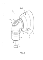
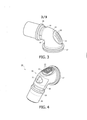
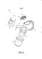
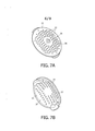
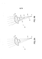
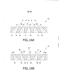
A Figura 1 é uma vista isométrica parcial, anterior de uma máscara respiratória de acordo com uma realização da invenção; a Figura 2 é uma vista isométrica anterior do cotovelo de giro da Figura 1 de acordo com uma realização da invenção; as Figuras 3 e 4 são vistas isométricas anteriores de um cotovelo de giro de acordo com realizações alternativas da invenção; a Figura 5 é uma vista explodida do cotovelo de giro da Figura 4 de acordo com uma realização da invenção; a Figura 6 é uma vista em seção transversal docotovelo de giro da Figura 4 de acordo com uma realização da invenção; as Figuras 7A e 7B são vistas isométricas anteriores e posteriores, respectivamente, de uma placa de 20 exalação de acordo com uma realização da invenção; a Figura 8 é uma vista em seção transversal lateral parcial de uma máscara respiratória de acordo com uma realização da invenção; as Figuras 9A e 9B são vistas isométricas laterais dos furos para ventilação em uma placa de exalação de acordo com uma realização da invenção; e as Figuras 10A e 10B são representações esquemáticas dos furos para ventilação em uma placa de exalação de acordo com realizações alternativas da invenção. Os termos direcionais utilizados na presenteinvenção, como, por exemplo, e sem limitação, parte superior, parte inferior, lado esquerdo, lado direito, partes superior, inferior, anterior, posterior e derivados destes referem-se à orientação dos elementos mostrados nos desenhos e não são limitados pelas reivindicações, a menos que esteja expressamente definido na presente invenção.Figure 1 is a partial, isometric, front view of a respiratory mask according to an embodiment of the invention; Figure 2 is an anterior isometric view of the turning elbow of Figure 1 according to an embodiment of the invention; Figures 3 and 4 are anterior isometric views of a turning elbow according to alternative embodiments of the invention; Figure 5 is an exploded view of the turning elbow of Figure 4 according to an embodiment of the invention; Figure 6 is a cross-sectional view of the rotating elbow of Figure 4 according to an embodiment of the invention; Figures 7A and 7B are front and rear isometric views, respectively, of an exhalation plate according to an embodiment of the invention; Figure 8 is a partial lateral cross-sectional view of a respiratory mask according to an embodiment of the invention; Figures 9A and 9B are side isometric views of the ventilation holes in an exhalation plate according to an embodiment of the invention; and Figures 10A and 10B are schematic representations of the ventilation holes in an exhalation plate according to alternative embodiments of the invention. The directional terms used in the present invention, such as, without limitation, top, bottom, left side, right side, top, bottom, front, back and derivatives of these refer to the orientation of the elements shown in the drawings and are not limited by the claims, unless expressly defined in the present invention.
Conforme empregado na presente invenção, o termo 5 "dispositivo com interface" refere-se a qualquer mecanismo apropriado para transportar um gás de e/ou para a via aérea de um usuário e inclui expressamente, mas não se limita aos dispositivos com interface não-invasivos tais como as máscaras (por exemplo, sem limitação, as máscaras faciais 10 completas, máscaras nasais e máscaras para descanso que têm elementos de suporte tais como suportes para testa e almofadas para as bochechas, incluindo, sem limitação, a máscara facial Total’* comercializada pelo cessionário desta).As used in the present invention, the term "device with interface" refers to any mechanism suitable for transporting a gas to and / or into a user's airway and expressly includes, but is not limited to, devices with a non-interface. invasive such as masks (for example, without limitation,
Conforme empregado na presente invenção, a 15 indicação que duas ou mais porções ou componentes estão "acoplados" ou "conectados" significa que as partes estão unidas ou operam conjuntamente de maneira direta ou através de uma ou mais porções intermediárias ou componentes.As used in the present invention, the indication that two or more portions or components are "coupled" or "connected" means that the parts are joined or operate directly together or through one or more intermediate portions or components.
Conforme empregado na presente invenção, o termo 20 "número" significa um ou um número inteiro maior do que um (isto é, uma pluralidade).As used in the present invention, the term 20 "number" means one or an integer greater than one (i.e., a plurality).
A Figura 1 é uma vista isométrica parcial, anterior de uma máscara respiratória 10 de acordo com uma realização da invenção. Conforme mostrado na Figura 1, a máscara 25 respiratória 10 inclui um corpo principal 11 que tem uma placa anterior 12. Um dispositivo de acoplamento fluido na forma de um cotovelo de giro 15 é acoplado à placa anterior 12. O cotovelo de giro 15 serve para a aplicação de um fluido, tal como um gás respirável, de uma fonte de gás 30 externa 5, tal como um ventilador ou outro dispositivo apropriado, à máscara 10.Figure 1 is a partial, isometric, front view of a
A fonte de gás externa 5, que também é denominada tipicamente como um sistema de suporte de pressão 32, é qualquer sistema de suporte de ventilação ou de pressão convencional. Os exemplos de tais sistemas de suporte de pressão incluem, mas não são limitados a: um ventilador, um dispositivo de pressão de via aérea positiva contínua (CPAP) 5 ou um dispositivo de pressão variável, por exemplo, um dispositivo de auto-titulação, dispositivo de ventilação assistida proporcional (PAV®), dispositivo de pressão de via aérea positiva proporcional, dispositivo C-Flex™, dispositivo Bi-Flex™ ou um dispositivo BiPAP® manufaturado e distribuído pela Philips Respironics, Inc. de Pittsburgh, PA, em que a pressão provida ao paciente varia com o ciclo respiratório do paciente, de modo que uma pressão mais elevada é aplicada durante a inspiração em vez de durante a expiração, ou outro dispositivo de suporte de pressão. Outros dispositivos que comunicam um fluxo de gás com uma via aérea de um paciente apropriados para o uso na presente invenção incluem os dispositivos que aplicam uma pressão elevada e baixa ou positiva e negativa à via aérea para finalidades de liberação ou afrouxamento de secreções. O cotovelo de giro 15 tem um corpo principal 16 comuma primeira extremidade do cotovelo 17 conectada à placa anterior 12 da máscara 10 (recebida através de uma entrada (não mostrada) provida na placa anterior 12), e uma segunda extremidade do cotovelo oposta 19 para conexão a uma fonte de gás externa (não mostrada) através de um ou mais condutos adicionais (não mostrados)„ A primeira extremidade do cotovelo 17 pode ser rosqueada para prover o movimento de giro com respeito à placa anterior 12. Alternativamente, a primeira extremidade do cotovelo 17 pode não ser rosqueada e, portanto, não ser conectada de maneira giratória à placa anterior 12.The
Conforme mostrado na Figura 1, a segundaextremidade do cotovelo 19 não é rosqueada e, portanto, não provê um movimento de giro com respeito à fonte de gás externa ou quaisquer condutos conectados à fonte de gás externa. Alternativamente, a segunda extremidade do cotovelo 19 pode ser rosqueada para prover um movimento de giro com respeito à fonte de gás externa. Desse modo, em realizações alternativas, a primeira extremidade do cotovelo 17 e a segunda extremidade do cotovelo 19 podem ser rosqueadas para prover um movimento de giro, ou somente à segunda extremidade do cotovelo 19 pode ser rosqueada, ou somente a primeira extremidade do cotovelo 17 pode ser rosqueada, ou nem a primeira extremidade do cotovelo 17 nem a segunda extremidade do cotovelo 19 podem ser rosqueadas, a fim de impossibilitar um movimento de giro com respeito à placa anterior 12 e a fonte de gás externa.As shown in Figure 1, the second end of the
Conforme mostrado na Figura 1, uma placa de exalação 21 é acoplada de maneira removível ao corpo principal 16 do cotovelo de giro 15. A placa de exalação 21 inclui uma pluralidade de pequenos furos para ventilação 22, que podem ser arranjados em uma ampla variedade de padrões de difusão. Na realização exemplificadora mostrada na Figura 1, os furos para ventilação 22 são arranjados em um padrão similar à grade linear. Isto, no entanto, serve como exemplo somente, e ficará compreendido que os padrões apropriados incluem qualquer outra configuração que permita que o gás de exaustão expirado pelo usuário saia através dos furos para ventilação 22 do cotovelo de giro 15 à atmosfera. Além disso, a placa de exalação 21, como mostrado na Figura 1, está em um formato oval alongado. Isto também serve como exemplo somente, e formatos alternativos apropriados podem incluir qualquer formato que possa ser incorporado no cotovelo de giro 15.As shown in Figure 1, an
A Figura 2 ê uma vista isométrica anterior do cotovelo de giro 15 da Figura 1 que mostra a placa de exalação 21 removida do mesmo. Como mostrado na Figura 2, o corpo principal 16 do cotovelo de giro 15 define uma abertura 23 a que a placa de exalação 21 é unida de maneira removível. A placa de exalação 21 pode ser unida ao cotovelo de giro 15 5 dentro da abertura 23 utilizando uma ampla variedade de mecanismos de fixação conhecidos no estado da técnica, como pelo ajuste de pressão mecânica (mostrado na Figura 2) , soldagem sônica ou colagem.Figure 2 is an anterior isometric view of the rotating
Uma vez que a placa de exalação 21 é separada do 10 restante do cotovelo de giro 15, pode ser manufaturada separadamente do restante do cotovelo de giro 15 e não fica, desse modo, sujeita às limitações que podem ser impostas pelo processo utilizado para manufaturar o restante do cotovelo de giro 15 tais como, por exemplo, as limitações impostas por um 15 processo de moldagem como descrito na seção Fundamentos da Invenção. Tais limitações podem, por exemplo, impedir que a circunferência maior dos furos para ventilação 22 se encontre na superfície interna do cotovelo de giro 15. Além disso, já que a placa de exalação 21 é removível, pode ser prontamente 20 substituída como necessário, como quando se torna danificada de alguma maneira»Since the
A Figura 3 é uma vista isométrica anterior do cotovelo de giro 24 de acordo com uma realização alternativa da invenção. Conforme visto na Figura 3, o cotovelo de giro 25 24 inclui um número dos mesmos componentes incluídos comoparte do cotovelo de giro 15 mostrado nas Figuras 1 e 2, que inclui uma primeira extremidade do cotovelo 17 para conexão a uma porção de uma máscara, tal como a placa anterior 12 mostrada na Figura 1 (não mostrada na Figura 3), uma segunda 30 extremidade do cotovelo oposta 19, uma placa de exalação removível 21 e os furos para ventilação 22. Além disso, como mostrado na Figura 3, um conduto de giro 26 é acoplado à segunda extremidade do cotovelo 19. 0 conduto de giro 26 provê um movimento de giro do mesmo relativo ao cotovelo de giro 24. Desse modo, como mostrado na Figura 3, a primeira extremidade do cotovelo 17 e a segunda extremidade do cotovelo 19 oferecem um movimento de giro.Figure 3 is an anterior isometric view of the
A Figura 4 é uma vista isométrica anterior, a Figura 5 é uma vista explodida e a Figura 6 é uma vista em seção transversal do cotovelo de giro 26 de acordo com outra realização da invenção. Conforme mostrado na Figura 4, o cotovelo de giro 28 inclui um número dos mesmos componentes incluídos como parte do cotovelo de giro 24 mostrado na Figura 3, incluindo um corpo principal 16, uma primeira extremidade do cotovelo 17, uma segunda extremidade do cotovelo oposta 19, um conduto de giro 2 6 e uma placa de exalação removível 21 que tem furos para ventilação 22. Além disso, tal como mostrado nas Figuras 4, 5 e 6, o cotovelo de giro 28 inclui uma válvula de penetração 3 0 que provê a entrada de ar como necessário, por exemplo, no caso de uma obstrução no conduto que alimenta o cotovelo de giro 28.Figure 4 is an anterior isometric view, Figure 5 is an exploded view and Figure 6 is a cross-sectional view of the turning
Como mostrado nas Figuras 4, 5 e 6, a válvula de penetração 30 é posicionada no corpo principal 16 do cotovelo de giro 28 entre a segunda extremidade do cotovelo 19 e a placa de exalação 21. A válvula de penetração 30 é separável do corpo principal 16 e pode ser acoplada ao corpo principal 16 utilizando uma ampla variedade de mecanismos de fixação conhecidos no estado da técnica, como pelo ajuste de pressão mecânica, soldagem sônica ou colagem.As shown in Figures 4, 5 and 6, the
Com referência às Figuras 4, 5 e 6, a válvula de penetração 30 inclui uma abertura 31, um assento de borda de faca 32, um disco 33 e uma mola 34. Se a pressão dentro do canal definido na válvula de penetração for igual a ou menor do que a atmosfera ambiental, a mola 34 fará com que o disco 33 feche, desse modo permitindo que o ar flua através da abertura 31 da válvula de penetração 30. A mola 34 pode ser qualquer mecanismo de impulsão apropriado, que inclui, por exemplo, uma dobradiça viva. Por outro lado, uma pequena pressão positiva (durante a operação normal da máscara) faz com que o disco 33 se erga, acopla o assento de borda de faca 5 32 e cobre a abertura 31 da válvula de penetração 30,permitindo que o ar flua livremente através do cotovelo 2θ à máscara 10.Referring to Figures 4, 5 and 6, the
A Figura 7A é uma vista isométrica anterior e aFigura 7B é uma vista isométrica posterior da placa de 10 exalação 21 que tem os furos de ventilação 22, tal como mostrado nas Figuras 1, 2, 3, 4 e 5 de acordo com umarealização particular e não-limitadora. A Figura 7A mostra uma superfície externa 35 da placa deexalação 21, e a Figura 7B mostra uma superfície interna 37 da placa de exalação 21.Além disso, a Figura 7A mostra uma circunferência externa 36 dos furos para ventilação 22. Como utilizado na presente invenção, o termo "circunferência” refere-se a um perímetro contínuo que tem qualquer formato, incluindo, sem limitação, circular, oblongo, retangular e triangular. A Figura 7B 20 mostra a circunferência interna 37 dos furos para ventilação 22 .Figure 7A is an anterior isometric view and Figure 7B is a posterior isometric view of the
Conforme visto pela comparação da Figura 7A com aFigura 7B, a circunferência externa (por exemplo, circular) 36 dos furos para ventilação 22 na realização particular 25 mostrada é menor do que a circunferência interna (por exemplo, oblonga) 37 dos furos para ventilação 22. Desse modo, os furos para ventilação 22 nesta realização têm um formato afunilado, que se afunila a partir da circunferência interna 37 à circunferência externa 36. Em particular, os 30 furos para ventilação 22 têm um formato geralmente cônico que se afunila de uma circunferência interna em formato oblongo 37 a uma circunferência externa circular 36. Alternativamente, os furos para ventilação 22 podem ter um formato cônico verdadeiro que se afunila a partir de uma base circular, ou qualquer outro formato afunilado apropriado que, por exemplo, e sem limitação, seja afunilado de um a partir de um formato quadrado, retangular ou alguma outra base de formato. Conforme será apreciado, a criação de um cotovelo por meio de um processo de moldagem que inclui tais furos para ventilação afunilados (a área maior para dentro) diretamente no cotovelo requereria um molde complexo. A necessidade de tal molde complexo é eliminada com a 10 utilização da placa de exalação formada separadamente 21.As seen by comparing Figure 7A with Figure 7B, the outer circumference (e.g., circular) 36 of the ventilation holes 22 in the particular embodiment 25 shown is smaller than the inner circumference (e.g., oblong) 37 of the ventilation holes 22 Thus, the ventilation holes 22 in this embodiment have a tapered shape, which tapers from the
As Figuras 7A e 7B servem como exemplos somente, e ficará compreendido que, em uma realização alternativa, os furos para ventilação 22 podem ter um formato afunilado, que se afunila a partir da circunferência externa 36 à 15 circunferência interna 37. Desse modo, os furos para ventilação 22 podem ter um formato geralmente cônico que se afunila a partir de um formato oblongo ou em outro formato da circunferência externa 36 (por exemplo, retangular, triangular) a uma circunferência interna 37 circular menor ou 20 outro formato de circunferência (por exemplo, retangular, triangular).Figures 7A and 7B serve as examples only, and it will be understood that, in an alternative embodiment, the ventilation holes 22 may have a tapered shape, which tapers from the
A Figura 8 é uma vista em seção transversal lateral parcial de uma máscara respiratória 101 de acordo com uma realização da invenção que incorpora a realização particular 25 da placa de exalação 21 mostrada nas Figuras 7A e 7B. Tal como visto na Figura 8, a máscara 10' inclui um número dos mesmos componentes incluídos como parte da máscara 10 na Figura 1, que inclui o cotovelo de giro 15, uma primeira extremidade do cotovelo 17 conectada à placa anterior 12, uma 30 segunda extremidade do cotovelo oposta 19 e a placa de exalação 21 que tem os furos para ventilação 22, como descrito. Além disso, tal como mostrado na Figura 8 e como descrito, os furos para ventilação 22 são geralmente cônicos no formato com a circunferência maior posicionada na superfície interna 37 (mostrada na Figura 7B) da placa de exalação 21, e a circunferência menor posicionada na superfície externa 36 da placa de exalação 21. Preferivelmente, os furos para ventilação 22 têm dimensões de uma maneira tal que a relação entre a ãrea da circunferência maior (por exemplo, oblonga) e a área da circunferência menor (por exemplo, circular) é maior do que 1.Figure 8 is a partial side cross-sectional view of a breathing mask 101 according to an embodiment of the invention that incorporates the particular embodiment 25 of the
Além disso, a descarga do fluxo de exaustão do 10 cotovelo de giro 15, 24, ou 28, conforme as circunstâncias, através dos furos para ventilação 22 da placa de exalação 21 incluída no mesmo, pode ser controlada e variada ao alterar os ângulos (isto é, o grau de afunilamento) dos furos para ventilação 22. Por exemplo, cada um dos furos para ventilação 15 22 pode ser estruturado para ter um ângulo diferente, ou osconjuntos predeterminados de furos para ventilação 22 podem ter, cada um, um ângulo respectivo, comum para a formação de um padrão específico, ou todos os furos para ventilação 22 pode ter o mesmo ângulo, conforme desejado. Desse modo, o 20 fluxo de exaustão pode ser variado enquanto a estrutura física do cotovelo de giro 15, 24, ou 28 e da placa de exaustão 21 permanece inalterada.In addition, the exhaust flow discharge from the turning
A realização particular dos furos para ventilação 22 mostrados nas Figuras 7A e 7B também oferece a redução do - 25 ruído do fluxo de exaustão. Em particular, uma redução no ruído pode ser conseguida ao descarregar o fluxo de exaustão através dos furos para ventilação afunilados 22 em que todos os furos para ventilação 22 têm ângulos incidentes que são irradiados a partir da parte interna do cotovelo de giro 15, 30 tal como ilustrado na Figura 8 e que se originam de um ponto comum. Como mostrado na Figura S, cada fluxo de exaustão individual (raio) sai em direção à atmosfera a um ângulo exclusivo, de uma maneira tal que os fluxos (raios) não se cruzam. Isto elimina a ressonância e reduz o nível de ruído. Alternativamente, múltiplos conjuntos de furos para ventilação 22 podem ter múltiplos pontos comuns de origem correspondentes (vide, por exemplo, as Figuras 9A e 9B 5 descritas em detalhe abaixo, que mostram uma realização particular).The particular design of the ventilation holes 22 shown in Figures 7A and 7B also offers the reduction of exhaust flow noise. In particular, a reduction in noise can be achieved by discharging the exhaust flow through the tapered ventilation holes 22 where all ventilation holes 22 have incident angles that are radiated from the inside of the turning
As Figuras 9A e 9B são vistas isométricas laterais da placa de exalação 21 e dos furos para ventilação 22 de acordo com uma realização particular e não-limitadora. A 10 Figura 9A mostra um fluxo de exaustão 4 0 que compreende múltiplos raios que são descarregados através de cada um dos furos para ventilação 22 que têm ângulos incidentes que irradiam da parte interna de um cotovelo de giro (não mostrado) e se originam de um ponto comum A. Cada um dos 15 raios individuais 42 do fluxo de exaustão 4 0 sai de cada um dos furos para ventilação associado 22s em direção à atmosfera a um ângulo exclusivo de uma maneira tal que cada um dos raios 42 não se cruza com o outro.Figures 9A and 9B are side isometric views of the
A Figura 9B mostra um fluxo de exaustão 44 que tem 20 um componente de fluxo 46 que compreende múltiplos raios 48 e um componente de fluxo 50 que compreende múltiplos raios 52. Cada um dos raios 48 sai de um furo para ventilação associado 22, e cada um deles tem um ângulo incidente que se origina de um ponto comum A. Similarmente, cada um dos raios 52 sai de ■ 25 um furo para ventilação associado 2 2 e têm um ângulo incidente que se origina de um ponto comum B. Na realização particular mostrada na Figura 8B, o ponto de origem B se encontra aproximadamente a meio caminho da superfície interna 37 como o ponto de origem A. Contempla-se que o conjunto de 30 furos para ventilação 22 que corresponde ao ponto de origem B tenha ângulos de difusão aumentados em comparação ao conjunto de furos para ventilação 22 que correspondem ao ponto de origem A.Figure 9B shows an exhaust flow 44 that has a
A Figura lOA é uma representação esquemática de uma porção da placa de exalação 21 que tem os furos para ventilação 22 formados de acordo com uma realização preferida particular da invenção. Conforme visto na Figura 10A, cada furo para ventilação 22 é definido por uma parede interna reta contínua 54 formada dentro da placa de exalação 21, a qual se estende da superfície interna 37 à superfície externa 35. Em outras palavras, as paredes internas 54 não se curvam ou não se inclinam à medida que se estendem da superfície interna 37 à superfície externa 35.Figure 10A is a schematic representation of a portion of the
Na realização mostrada na Figura 10A, a circunferência externa 36 de cada furo para ventilação 22 é menor do que a circunferência interna 38 do furo para ventilação 22, a parede interna 54 é estruturada de uma maneira tal que a circunferência externa 3 6 do furo para ventilação 22 é deslocada (isto é, não centrada) com respeito à circunferência interna 38 do furo para ventilação 22. Conforme visto na Figura 10A, o deslocamento particular resulta em raios de fluxo convergentes. A Figura 10B é uma representação esquemática de uma realização alternativa da placa de exalação 21 que tem as paredes internas retas contínuas 54 em que o deslocamento da circunferência externa 36 com respeito à circunferência interna 38 de cada furo para ventilação 22 à exceção do furo para ventilação central 22 é tal que raios de fluxo divergentes são produzidos.In the embodiment shown in Figure 10A, the
Embora as realizações preferidas da invenção tenham sido descritas e ilustradas acima, deve ficar compreendido que estas são exemplificadoras da invenção e não devem ser consideradas como limitadoras. Adições, apagamentos, substituições e outras modificações podem ser feitos sem que se desvie do caráter ou âmbito da presente invenção. Por exemplo, e sem limitação, a placa de exalação 21 de acordo com qualquer uma das realizações particulares aqui descritas pode ser introduzida diretamente na placa anterior de uma máscara em vez de ser introduzida em um dispositivo de acoplamento fluido acoplado à máscara (como mostrado na Figura 1) . Consequentemente, a invenção não deve ser ' 5 considerada como limitada pela descrição antecedente, mas é limitada somente pelo âmbito das reivindicações anexas.Although the preferred embodiments of the invention have been described and illustrated above, it should be understood that they are exemplary of the invention and are not to be considered as limiting. Additions, deletions, substitutions and other modifications can be made without departing from the character or scope of the present invention. For example, and without limitation, the
Embora a invenção tenha sido descrita em detalhe com a finalidade de ilustração com base na consideração atual sobre as realizações mais práticas e preferidas, deve ficar 10 compreendido de que tal detalhe é unicamente para essa finalidade e que a invenção não se limita às realizações descritas, mas, pelo contrário, presta-se a cobrir modificações e arranjos equivalentes que estejam dentro caráter e âmbito das reivindicações anexas. Por exemplo, deve 15 ficar compreendido que a presente invenção contempla que, à extensão possível, uma ou mais características de qualquer realização podem ser combinadas com uma ou mais características de qualquer outra realização.Although the invention has been described in detail for the purpose of illustration based on the current consideration of the most practical and preferred embodiments, it should be understood that such detail is for that purpose only and that the invention is not limited to the described embodiments, but, on the contrary, it lends itself to cover modifications and equivalent arrangements that are within the character and scope of the appended claims. For example, it should be understood that the present invention contemplates that, to the extent possible, one or more characteristics of any embodiment can be combined with one or more characteristics of any other embodiment.
Claims (10)
Applications Claiming Priority (3)
| Application Number | Priority Date | Filing Date | Title |
|---|---|---|---|
| US12159108P | 2008-12-11 | 2008-12-11 | |
| US61/121,591 | 2008-12-11 | ||
| PCT/IB2009/055249 WO2010067237A2 (en) | 2008-12-11 | 2009-11-21 | Exhaust vent configuration |
Publications (4)
| Publication Number | Publication Date |
|---|---|
| BRPI0917618A2 BRPI0917618A2 (en) | 2010-06-17 |
| BRPI0917618A8 BRPI0917618A8 (en) | 2019-09-10 |
| BRPI0917618B1 true BRPI0917618B1 (en) | 2021-03-09 |
| BRPI0917618B8 BRPI0917618B8 (en) | 2021-07-20 |
Family
ID=41666415
Family Applications (1)
| Application Number | Title | Priority Date | Filing Date |
|---|---|---|---|
| BRPI0917618A BRPI0917618B8 (en) | 2008-12-11 | 2009-11-21 | respiratory interface device, fluid coupling device for a respiratory interface device, and exhalation mechanism for a respiratory interface device |
Country Status (6)
| Country | Link |
|---|---|
| US (1) | US9174018B2 (en) |
| EP (1) | EP2376166A2 (en) |
| JP (1) | JP5513517B2 (en) |
| CN (1) | CN102245251B (en) |
| BR (1) | BRPI0917618B8 (en) |
| WO (1) | WO2010067237A2 (en) |
Families Citing this family (56)
| Publication number | Priority date | Publication date | Assignee | Title |
|---|---|---|---|---|
| WO2011014931A1 (en) * | 2009-08-07 | 2011-02-10 | Resmed Ltd | Patient interface systems |
| USD656231S1 (en) * | 2009-04-20 | 2012-03-20 | Resmed Limited | Respiratory mask |
| EP4218874B1 (en) | 2009-12-23 | 2025-11-26 | Fisher & Paykel Healthcare Limited | An interface |
| CN103180005B (en) | 2010-10-22 | 2016-01-20 | 皇家飞利浦电子股份有限公司 | There is the fluid connecting duct of waste gas noise reduction |
| JP6351263B2 (en) | 2011-02-16 | 2018-07-04 | レスメド・リミテッドResMed Limited | Mask vent |
| US10603456B2 (en) | 2011-04-15 | 2020-03-31 | Fisher & Paykel Healthcare Limited | Interface comprising a nasal sealing portion |
| CA2833106C (en) | 2011-04-15 | 2019-08-27 | Fisher & Paykel Healthcare Limited | Interface comprising a rolling nasal bridge portion |
| US9950130B2 (en) | 2012-09-04 | 2018-04-24 | Fisher & Paykel Healthcare Limited | Valsalva mask |
| US10589046B2 (en) | 2012-10-17 | 2020-03-17 | Fisher & Paykel Healthcare Limited | Interface comprising a nasal sealing portion and a rolling hinge |
| CA2891782A1 (en) | 2012-11-16 | 2014-05-22 | Fisher & Paykel Healthcare Limited | Nasal seal and respiratory interface |
| US11235120B2 (en) | 2013-03-15 | 2022-02-01 | Lucy Carol Davis | Facial mask apparatus with removable filter |
| US10004866B2 (en) | 2013-03-15 | 2018-06-26 | Lucy Carol Davis | Facial mask apparatus and method of making |
| US20140261430A1 (en) * | 2013-03-15 | 2014-09-18 | Lucy Carol Davis | Facial Mask Apparatus and Method of Making |
| US11235119B2 (en) | 2013-03-15 | 2022-02-01 | Lucy Carol Davis | Facial mask apparatus and method of making |
| BR302013005431S1 (en) * | 2013-05-07 | 2014-09-09 | Koninkl Philips Nv | CONFIGURATION APPLIED TO ELBOW PATIENT INTERFACE SET CONNECTOR |
| CN105555345B (en) | 2013-08-05 | 2018-03-30 | 费雪派克医疗保健有限公司 | Combination for the interface used in positive pressure respiration treatment is provided and its with face shield assembly |
| EP3033131B1 (en) * | 2013-08-12 | 2020-05-06 | Koninklijke Philips N.V. | Fluid coupling member including valve member |
| TWD164237S (en) * | 2013-09-06 | 2014-11-11 | 雃博股份有限公司 | Parts of a breathing mask |
| NZ718810A (en) | 2013-10-03 | 2017-10-27 | Resmed Ltd | Mask vent with side wall |
| WO2015092589A1 (en) * | 2013-12-18 | 2015-06-25 | Koninklijke Philips N.V. | Fluid connector with exhaust valve |
| US10953190B2 (en) * | 2014-05-19 | 2021-03-23 | Fisher & Paykel Healthcare Limited | Pressure controlled exhaust vent |
| JP6684727B2 (en) | 2014-06-17 | 2020-04-22 | フィッシャー アンド ペイケル ヘルスケア リミテッド | Patient interface |
| US11027087B2 (en) | 2014-07-18 | 2021-06-08 | Fisher & Paykel Healthcare Limited | Headgear clip arrangement |
| EP3174587B1 (en) * | 2014-07-31 | 2019-03-13 | Koninklijke Philips N.V. | Fluid coupling conduit for a patient interface device |
| SG10202102503YA (en) | 2014-08-25 | 2021-04-29 | Fisher & Paykel Healthcare Ltd | Respiratory mask and related portions, components or sub-assemblies |
| ES2833375T3 (en) * | 2014-10-27 | 2021-06-15 | Breas Medical Inc | Nasal mask for use in various positive airway pressure delivery systems |
| USD797921S1 (en) * | 2014-11-07 | 2017-09-19 | Fisher & Paykel Healthcare Limited | Breathing apparatus |
| EP3237281B1 (en) * | 2014-12-22 | 2019-05-08 | AMEO Sports GmbH | Breathing aid for swimmers |
| US10765824B2 (en) | 2015-01-30 | 2020-09-08 | ResMed Pty Ltd | Patient interface comprising a gas washout vent |
| AU2016227361B2 (en) | 2015-03-04 | 2020-05-14 | Fisher & Paykel Healthcare Limited | Mask system headgear |
| US10994090B2 (en) | 2015-09-04 | 2021-05-04 | Fisher & Paykel Healthcare Limited | Patient interfaces |
| CN108136150B (en) * | 2015-09-23 | 2020-11-03 | 瑞思迈私人有限公司 | Ventilation adapters for respiratory therapy systems |
| CN105327433A (en) * | 2015-12-10 | 2016-02-17 | 李燕梅 | Medical emergency atomizer for pediatrics department |
| US20180361096A1 (en) | 2015-12-16 | 2018-12-20 | Koninklijke Philips N.V. | Respiratory interface device including custom features |
| USD882066S1 (en) | 2016-05-13 | 2020-04-21 | Fisher & Paykel Healthcare Limited | Frame for a breathing mask |
| SG11201811028QA (en) * | 2016-07-08 | 2019-01-30 | Fisher & Paykel Healthcare Ltd | A vent for a component of a respiratory therapy system |
| EP4122516B1 (en) | 2016-10-05 | 2025-03-12 | Fisher & Paykel Healthcare Limited | Patient interfaces |
| US10578186B2 (en) * | 2016-10-31 | 2020-03-03 | Emerson Process Management Regulator Technologies, Inc. | Spring seat vibration damper apparatus for use with pressure regulators |
| USD823454S1 (en) | 2017-02-23 | 2018-07-17 | Fisher & Paykel Healthcare Limited | Cushion assembly for breathing mask assembly |
| USD824020S1 (en) | 2017-02-23 | 2018-07-24 | Fisher & Paykel Healthcare Limited | Cushion assembly for breathing mask assembly |
| USD823455S1 (en) | 2017-02-23 | 2018-07-17 | Fisher & Paykel Healthcare Limited | Cushion assembly for breathing mask assembly |
| USD874646S1 (en) | 2017-03-09 | 2020-02-04 | Fisher & Paykel Healthcare Limited | Headgear component for a nasal mask assembly |
| USD901673S1 (en) | 2017-03-09 | 2020-11-10 | Fisher & Paykel Healthcare Limited | Frame and breathing tube assembly for a nasal mask |
| CN106943656A (en) * | 2017-03-31 | 2017-07-14 | 宁波圣宇瑞医疗器械有限公司 | Noninvasive breathing mask and its lung ventilator applied |
| EP3618910B1 (en) | 2017-05-01 | 2023-12-27 | Fisher & Paykel Healthcare Limited | Conduit connector assembly of a patient interface, an anti-asphyxia valve for a conduit connector assembly and a connector |
| USD875242S1 (en) | 2017-09-20 | 2020-02-11 | Fisher & Paykel Healthcare Limited | Nasal mask and breathing tube set |
| USD855793S1 (en) | 2017-09-20 | 2019-08-06 | Fisher & Paykel Healthcare Limited | Frame for a nasal mask |
| CN107823771A (en) * | 2017-11-28 | 2018-03-23 | 宁波圣宇瑞医疗器械有限公司 | Mask joint and its malleation mask applied |
| EP3746163B1 (en) * | 2018-02-02 | 2023-12-20 | ResMed Pty Ltd | Patient interface having a connector assembly |
| USD884153S1 (en) | 2018-04-04 | 2020-05-12 | Fisher & Paykel Healthcare Limited | Frame for a mask assembly |
| TWI737934B (en) * | 2018-09-14 | 2021-09-01 | 雃博股份有限公司 | Respiratory mask |
| US11906097B2 (en) | 2019-09-04 | 2024-02-20 | Vyaire Medical, Inc. | Ventilation leak component |
| EP4045120B1 (en) | 2019-10-14 | 2025-11-26 | Fisher & Paykel Healthcare Limited | Respiratory interface assembly |
| EP4054688B1 (en) * | 2019-11-07 | 2025-03-19 | ResMed Pty Ltd | Vent for a respiratory system |
| USD1118899S1 (en) | 2021-04-13 | 2026-03-17 | Fisher & Paykel Healthcare Limited | Nasal mask |
| CN113926039B (en) * | 2021-09-30 | 2026-01-02 | 天津怡和嘉业医疗科技有限公司 | Nasal pad and patient interface device |
Family Cites Families (14)
| Publication number | Priority date | Publication date | Assignee | Title |
|---|---|---|---|---|
| US5690096A (en) * | 1996-03-14 | 1997-11-25 | Burch; John M. | Pediatric oxygenation device |
| AUPO504597A0 (en) * | 1997-02-10 | 1997-03-06 | Resmed Limited | A mask and a vent assembly therefor |
| JP4818569B2 (en) | 2000-12-22 | 2011-11-16 | レスメド・リミテッド | mask |
| US6851425B2 (en) | 2001-05-25 | 2005-02-08 | Respironics, Inc. | Exhaust port assembly for a pressure support system |
| US7357136B2 (en) * | 2003-08-18 | 2008-04-15 | Ric Investments, Llc | Patient interface assembly and system using same |
| EP3838323B1 (en) | 2003-09-03 | 2023-04-05 | Fisher & Paykel Healthcare Limited | Respiratory mask with gas washout vent |
| WO2005051468A1 (en) * | 2003-11-25 | 2005-06-09 | Resmed Limited | Vent system for cpap patient interface used in treatment of sleep disordered breathing |
| US9242060B2 (en) | 2004-07-23 | 2016-01-26 | Resmed Limited | Elbow for mask system |
| NZ567372A (en) * | 2005-10-17 | 2011-06-30 | Resmed Ltd | Anti-asphyxia valve assembly for respiratory mask with clip member to secure AAV assemblywithin an elbow |
| CA2602005A1 (en) * | 2006-09-18 | 2008-03-18 | Invacare Corporation | Breathing mask |
| US8205615B1 (en) * | 2006-09-29 | 2012-06-26 | Ric Investments, Llc | Self directing exhaust port assembly |
| WO2008058330A1 (en) | 2006-11-14 | 2008-05-22 | Resmed Ltd | Frame and vent assembly for mask assembly |
| US8875709B2 (en) | 2007-05-10 | 2014-11-04 | Resmed Limited | Mask assembly |
| US8573208B2 (en) * | 2008-05-07 | 2013-11-05 | Koninklijke Philips N.V. | Exhaust assembly |
-
2009
- 2009-11-21 US US13/131,616 patent/US9174018B2/en active Active
- 2009-11-21 JP JP2011540270A patent/JP5513517B2/en not_active Expired - Fee Related
- 2009-11-21 WO PCT/IB2009/055249 patent/WO2010067237A2/en not_active Ceased
- 2009-11-21 BR BRPI0917618A patent/BRPI0917618B8/en not_active IP Right Cessation
- 2009-11-21 CN CN200980149897.1A patent/CN102245251B/en active Active
- 2009-11-21 EP EP09764583A patent/EP2376166A2/en not_active Ceased
Also Published As
| Publication number | Publication date |
|---|---|
| EP2376166A2 (en) | 2011-10-19 |
| US20110240030A1 (en) | 2011-10-06 |
| JP2012511372A (en) | 2012-05-24 |
| CN102245251B (en) | 2016-03-09 |
| BRPI0917618B8 (en) | 2021-07-20 |
| BRPI0917618A2 (en) | 2010-06-17 |
| US9174018B2 (en) | 2015-11-03 |
| WO2010067237A2 (en) | 2010-06-17 |
| CN102245251A (en) | 2011-11-16 |
| BRPI0917618A8 (en) | 2019-09-10 |
| JP5513517B2 (en) | 2014-06-04 |
| WO2010067237A3 (en) | 2010-08-05 |
Similar Documents
| Publication | Publication Date | Title |
|---|---|---|
| BRPI0917618B1 (en) | device with a respiratory interface, fluid coupling device for a device with a respiratory interface and exhalation mechanism for a device with a respiratory interface | |
| EP3033131B1 (en) | Fluid coupling member including valve member | |
| US7934501B2 (en) | Swivel elbow for a patient interface | |
| AU2017293759B2 (en) | A vent for a component of a respiratory therapy system | |
| US9078989B2 (en) | Applicators for a nasal cannula | |
| US20190262569A1 (en) | Respiratory mask having gas washout vent and method for making the mask | |
| US10265496B2 (en) | Anti-asphyxia valve assembly | |
| US10589049B2 (en) | Fluid connector with exhaust valve | |
| BRPI0717547A2 (en) | PRESSURE REDUCTION VALVE, METHOD FOR PROVIDING BREATHING GAS, AND APPLIANCE FOR POSITIVE AIR PRESSURE GAS FLOW FOR A PATIENT AIR | |
| CN104717997A (en) | Patient interface device with frame and clips | |
| NZ769611A (en) | Mask vent | |
| JP2014518712A (en) | Rotary electrical connector and breathing gas supply system using this connector | |
| CN102781505A (en) | Patient interface device having cam wheel adjustment mechanism | |
| CN103874523B (en) | forehead gas supply assembly for a patient interface system | |
| CN221771193U (en) | A high-flow nasal oxygen cannula with adjustable flow rate | |
| CN104470573B (en) | Patient interface | |
| CN219941527U (en) | Oxygen regulating fixture | |
| WO2012073147A1 (en) | Patient interface device with multi-axis elbow conduit | |
| JP4922813B2 (en) | Gas supply tool for inhalation | |
| HK40035199B (en) | A mask for administering a breathable gas to a patient | |
| TWM561534U (en) | Breathing apparatus of continuous positive airway pressure having capability for positioning using angle | |
| CN107106807A (en) | Adjustable airflow diffuser |
Legal Events
| Date | Code | Title | Description |
|---|---|---|---|
| B06F | Objections, documents and/or translations needed after an examination request according [chapter 6.6 patent gazette] | ||
| B25D | Requested change of name of applicant approved |
Owner name: KONINKLIJKE PHILIPS N.V. (NL) |
|
| B25G | Requested change of headquarter approved |
Owner name: KONINKLIJKE PHILIPS N.V. (NL) |
|
| B06U | Preliminary requirement: requests with searches performed by other patent offices: procedure suspended [chapter 6.21 patent gazette] | ||
| B06A | Patent application procedure suspended [chapter 6.1 patent gazette] | ||
| B09A | Decision: intention to grant [chapter 9.1 patent gazette] | ||
| B16A | Patent or certificate of addition of invention granted [chapter 16.1 patent gazette] |
Free format text: PRAZO DE VALIDADE: 10 (DEZ) ANOS CONTADOS A PARTIR DE 09/03/2021, OBSERVADAS AS CONDICOES LEGAIS. |
|
| B16C | Correction of notification of the grant [chapter 16.3 patent gazette] |
Free format text: PRAZO DE VALIDADE: 20 (VINTE) ANOS CONTADOS A PARTIR DE 21/11/2009, OBSERVADAS AS CONDICOES LEGAIS. PATENTE CONCEDIDA CONFORME ADI 5.529/DF, QUE DETERMINA A ALTERACAO DO PRAZO DE CONCESSAO |
|
| B16C | Correction of notification of the grant [chapter 16.3 patent gazette] |
Free format text: REF. RPI 2618 DE 09/03/2021 QUANTO AO TITULO. |
|
| B21F | Lapse acc. art. 78, item iv - on non-payment of the annual fees in time |
Free format text: REFERENTE A 16A ANUIDADE. |
|
| B24J | Lapse because of non-payment of annual fees (definitively: art 78 iv lpi, resolution 113/2013 art. 12) |
Free format text: EM VIRTUDE DA EXTINCAO PUBLICADA NA RPI 2855 DE 23-09-2025 E CONSIDERANDO AUSENCIA DE MANIFESTACAO DENTRO DOS PRAZOS LEGAIS, INFORMO QUE CABE SER MANTIDA A EXTINCAO DA PATENTE E SEUS CERTIFICADOS, CONFORME O DISPOSTO NO ARTIGO 12, DA RESOLUCAO 113/2013. |