BRPI0904847B1 - orthopedic device to be associated with the outside of a bone - Google Patents
orthopedic device to be associated with the outside of a bone Download PDFInfo
- Publication number
- BRPI0904847B1 BRPI0904847B1 BRPI0904847-2A BRPI0904847A BRPI0904847B1 BR PI0904847 B1 BRPI0904847 B1 BR PI0904847B1 BR PI0904847 A BRPI0904847 A BR PI0904847A BR PI0904847 B1 BRPI0904847 B1 BR PI0904847B1
- Authority
- BR
- Brazil
- Prior art keywords
- clamp
- orthopedic device
- bone
- screws
- outside
- Prior art date
Links
Images


Classifications
-
- A—HUMAN NECESSITIES
- A61—MEDICAL OR VETERINARY SCIENCE; HYGIENE
- A61B—DIAGNOSIS; SURGERY; IDENTIFICATION
- A61B17/00—Surgical instruments, devices or methods, e.g. tourniquets
- A61B17/56—Surgical instruments or methods for treatment of bones or joints; Devices specially adapted therefor
- A61B17/58—Surgical instruments or methods for treatment of bones or joints; Devices specially adapted therefor for osteosynthesis, e.g. bone plates, screws, setting implements or the like
- A61B17/60—Surgical instruments or methods for treatment of bones or joints; Devices specially adapted therefor for osteosynthesis, e.g. bone plates, screws, setting implements or the like for external osteosynthesis, e.g. distractors, contractors
- A61B17/64—Devices extending alongside the bones to be positioned
- A61B17/6466—Devices extending alongside the bones to be positioned with pin-clamps movable along a solid connecting rod
- A61B17/6483—Devices extending alongside the bones to be positioned with pin-clamps movable along a solid connecting rod the connecting rod having a non-circular section
-
- A—HUMAN NECESSITIES
- A61—MEDICAL OR VETERINARY SCIENCE; HYGIENE
- A61B—DIAGNOSIS; SURGERY; IDENTIFICATION
- A61B17/00—Surgical instruments, devices or methods, e.g. tourniquets
- A61B17/56—Surgical instruments or methods for treatment of bones or joints; Devices specially adapted therefor
- A61B17/58—Surgical instruments or methods for treatment of bones or joints; Devices specially adapted therefor for osteosynthesis, e.g. bone plates, screws, setting implements or the like
- A61B17/60—Surgical instruments or methods for treatment of bones or joints; Devices specially adapted therefor for osteosynthesis, e.g. bone plates, screws, setting implements or the like for external osteosynthesis, e.g. distractors, contractors
- A61B17/66—Alignment, compression or distraction mechanisms
-
- A—HUMAN NECESSITIES
- A61—MEDICAL OR VETERINARY SCIENCE; HYGIENE
- A61B—DIAGNOSIS; SURGERY; IDENTIFICATION
- A61B17/00—Surgical instruments, devices or methods, e.g. tourniquets
- A61B2017/00367—Details of actuation of instruments, e.g. relations between pushing buttons, or the like, and activation of the tool, working tip, or the like
- A61B2017/00398—Details of actuation of instruments, e.g. relations between pushing buttons, or the like, and activation of the tool, working tip, or the like using powered actuators, e.g. stepper motors, solenoids
Abstract
DISPOSITIVO ORTOPÉDICO A SER ASSOCIADO COM O EXTERIOR DE UM OSSO A presente invenção refere-se ao dispositivo ortopédico (10; 110) a ser associado com 0 exterior de um osso e do tipo que compreende um trilho suporte (12; 112), estendido ao longo de um eixo longitudinal central (Y-Y) substancialmente paralelo ao osso (11; 111), pelo menos dois grampos (14, 18; 114, 118) montados deslizavelmente ao longo do dito eixo (Y -Y) no trilho suporte (12; 112) e suportado parafuso endosseous (16, 20; 116, 120) inseríveis no osso e um dispositivo desviador / compressor (58) removivelmente fixável nos dois grampos (14, 18; 114,118) por meio de respectivos pinos de conexão (68) inseridos nos correspondentes furos (64; 164) de cada grampo, em que cada grampo compreende um copo de grampo tendo uma base ou mordente inferior (24; 124) em uma tampa ou mordente superior (23; 123) bem como dois parafusos (25, 26; 164) para fixar 0 mordente superior (23; 123) no mordente inferior (24; 124). Vantajosamente, os furos (64; 164) para os pinos de conexão (68) são alinhados ao logo de uma linha (x; x') que é estendida substancialmente paralela ao dito eixo (Y -Y) com pelo menos um furo para os pinos de conexão do grampo restante também sendo alinhado ao longo da dita linha (x; x'), assim tornando a estrutura toda dos grampos montados no dispositivo ortopédico (10; 110) particularmente compacto.ORTHOPEDIC DEVICE TO BE ASSOCIATED WITH THE OUTSIDE OF A BONE The present invention relates to the orthopedic device (10; 110) to be associated with the outside of a bone and of the type comprising a support rail (12; 112), extended to the along a central longitudinal axis (YY) substantially parallel to the bone (11; 111), at least two clips (14, 18; 114, 118) slidably mounted along said axis (Y-Y) on the support rail (12; 112) and endosseous screw (16, 20; 116, 120) inserted into the bone and a diverter / compressor device (58) removably fixable on the two clamps (14, 18; 114,118) by means of the respective connecting pins (68) inserted in the corresponding holes (64; 164) of each clamp, each clamp comprising a clamp cup having a base or lower jaw (24; 124) in a cover or upper jaw (23; 123) as well as two screws (25, 26; 164) to fix the upper jaw (23; 123) to the lower jaw (24; 124). Advantageously, the holes (64; 164) for the connecting pins (68) are aligned along a line (x; x ') which is extended substantially parallel to said axis (Y-Y) with at least one hole for the connecting pins of the remaining clamp also being aligned along said line (x; x '), thus making the entire structure of the clamps mounted on the orthopedic device (10; 110) particularly compact.
Description
[001] A presente invenção refere-se no seu aspecto mais geral ao campo de ortopedia, em particular a um dispositivo ortopédico a ser associado com o exterior de um osso, tal como, por exemplo, um fixador externo para o osteossíntese de uma fratura óssea ou um dispositivo ortopédico para correção da deformação ou malformação óssea ou para a reconstrução de osso defeituoso. Tal dispositivo ortopédico é do tipo compreendendo um ou dois grampos montados em um trilho suporte que são movidos em uma maneira incremental de modo reciprocante, mais próximos a ou mais distantes um do outro por meio de um dispositivo compressor/desviador.[001] The present invention relates in its most general aspect to the field of orthopedics, in particular to an orthopedic device to be associated with the outside of a bone, such as, for example, an external fixator for the osteosynthesis of a fracture bone or an orthopedic device for correcting bone deformation or malformation or for the reconstruction of defective bone. Such an orthopedic device is of the type comprising one or two clamps mounted on a support rail that are moved in an incremental manner in a reciprocal manner, closer to or more distant from each other by means of a compressor / diverter device.
[002] Mesmo mais particularmente, a presente invenção refere-se a um grampo para o suporte de parafusos endósseos que é deslizavelmente montado no dito dispositivo ortopédico.[002] Even more particularly, the present invention relates to a clamp for the support of endoscopic screws that is slidably mounted on said orthopedic device.
[003] Para efeito de brevidade e simplificação, a seguinte descrição refere-se especificamente a um dispositivo ortopédico e aos grampos relativos para a correção das deformações em ossos longos, porém é pretendido que isto possa, por analogia, também ser estendido a qualquer dispositivo ortopédico externo com pelo menos dois grampos montados em um trilho suporte, eles próprios conectados por meio do dispositivo compressor/desviador.[003] For the sake of brevity and simplification, the following description refers specifically to an orthopedic device and the relative clamps for the correction of deformations in long bones, however it is intended that this can, by analogy, also be extended to any device external orthopedic with at least two clamps mounted on a support rail, connected by means of the compressor / diverter device.
[004] Na ortopedia, o uso de dispositivos ortopédicos que são associados com a parte externa de um osso é equipado com grampos para suportar parafusos endósseos que podem ser inseridos em ossos longos transversalmente, é bem conhecido, por exemplo, para a correção de uma deformação do osso ou para osteossíntese de uma fratura.[004] In orthopedics, the use of orthopedic devices that are associated with the external part of a bone is equipped with clamps to support endosseous screws that can be inserted into long bones transversely, it is well known, for example, for the correction of a bone deformation or for osteosynthesis of a fracture.
[005] Normalmente, tais dispositivos ortopédicos contêm dois grampos localizados a uma distância estabelecida um do outro em um trilho suporte. Cada grampo usualmente contém um mordente inferior e um mordente superior, fechados um em relação a outro, com sulcos transversais para guiar os parafusos endósseos.[005] Typically, such orthopedic devices contain two clamps located at an established distance from each other on a support rail. Each clamp usually contains a lower jaw and an upper jaw, closed in relation to each other, with transverse grooves to guide the endosseous screws.
[006] Mais particularmente, um primeiro grampo é colocado em correspondência com uma parte próxima do osso a fim de inserir os primeiros parafusos endósseos naquela posição e o outro grampo é colocado em uma posição distai correspondente do osso a fim de inserir os segundos parafusos endósseos naquela posição.[006] More particularly, a first clamp is placed in correspondence with a part near the bone in order to insert the first endosseous screws in that position and the other clamp is placed in a corresponding distal position of the bone in order to insert the second endosseous screws in that position.
[007] Quando o dispositivo ortopédico é usado para a correção de ossos longos deformados, a correção é usualmente realizada pela sujeição do osso à osteotomia entre a porção distal e proximal e mantendo contato entre duas extremidades de osso através dos parafusos endósseos. Sucessivamente, os dois grampos são movidos em etapas incrementais ao longo do trilho suporte com o auxílio de um dispositivo desviador/compressor de modo que, etapa por etapa, o calo de osso é gerado entre as extremidades.[007] When the orthopedic device is used for the correction of deformed long bones, the correction is usually performed by subjecting the bone to the osteotomy between the distal and proximal portion and maintaining contact between two bone ends through the endosseous screws. Then, the two clamps are moved in incremental steps along the support rail with the aid of a diverter / compressor device so that, step by step, the bone callus is generated between the ends.
[008] Mais particularmente, o dispositivo desviador/compressor é formado por um parafuso operador que é conectado aos grampos por meio dos respectivos pinos de conexão que são inseridos nos correspondentes furos ou cavidades cilíndricas no corpo de cada grampo. Pela rotação do parafuso, é então possível obter um deslocamento relativo dos dois grampos e como um resultado do movimento mais distante ou mais próximo das posições das extremidades dos ossos fixados nos mesmos.[008] More particularly, the diverter / compressor device is formed by an operator screw that is connected to the clamps by means of the respective connection pins that are inserted in the corresponding holes or cylindrical cavities in the body of each clamp. By rotating the screw, it is then possible to obtain a relative displacement of the two clamps and as a result of the movement further or closer to the positions of the ends of the bones attached to them.
[009] Tal dispositivo ortopédico, mesmo embora tenha muitos aspectos vantajosos e embora basicamente obtenha a meta para a qual se pretende, não obstante apresenta inconveniências conhecidas que ainda não foram superadas.[009] Such an orthopedic device, even though it has many advantageous aspects and although it basically obtains the goal for which it is intended, nevertheless presents known inconveniences that have not yet been overcome.
[0010] A inconveniência principal de tais dispositivos ortopédicos é devido ao fato que os grampos toma um grande espaço devido ao seu tamanho total, devido a necessidade que tem de acomodar dentro de cada corpo de grampo uma pluralidade de componentes e elementos funcionais tais como sulcos guias para os parafusos endósseos, os próprios parafusos endósseos, os furos para receber os pinos de conexão do compressor, os parafusos de fixação dos dois mordentes, bem como meios para bloquear os mordentes no trilho suporte. Para somar a isto, uma pluralidade de meios de fixação tem de coexistir no corpo de cada grampo.[0010] The main inconvenience of such orthopedic devices is due to the fact that the clips take up a large space due to their total size, due to the need that has to accommodate within each clip body a plurality of components and functional elements such as grooves guides for the endosseous screws, the endosseous screws themselves, the holes for receiving the compressor connection pins, the fixing screws of the two jaws, as well as means to block the jaws on the support rail. To add to this, a plurality of fixing means must coexist in the body of each clamp.
[0011] As grandes dimensões dos grampos, consequentemente, caem pesadamente sobre o peso total e dimensões do dispositivo ortopédico, bem como sobre o número máximo de grampos que podem ser colocados em um trilho suporte, dentro de um determinado peso.[0011] The large dimensions of the clamps, consequently, fall heavily on the total weight and dimensions of the orthopedic device, as well as on the maximum number of clamps that can be placed on a support rail, within a certain weight.
[0012] O problema técnico na base da presente invenção é aquele de conceber um grampo e um dispositivo ortopédico incluindo tal grampo, com tais características estrutural e funcional em que as inconveniências acima mencionadas em vista do estado da técnica são superadas, e, em particular um dispositivo que possa usar um grampo com as dimensões que são menores do que aquelas dos grampos do estado da técnica, porém com suporte para um número igual dos parafusos endósseos.[0012] The technical problem underlying the present invention is that of designing a clamp and an orthopedic device including such a clamp, with such structural and functional characteristics in which the above mentioned inconveniences in view of the state of the art are overcome, and in particular a device that can use a clamp with dimensions that are smaller than those of the state of the art clamps, but with support for an equal number of endosseous screws.
[0013] O problema técnico é solucionado por um dispositivo ortopédico do tipo previamente descrito e compreendendo um trilho suporte, que se estende ao longo de um eixo longitudinal central, substancialmente paralelo ao osso, pelo menos dois grampos montados deslizavelmente ao longo do dito eixo no trilho suporte e suportando os parafusos endósseos que podem ser inseridos no osso e um dispositivo desviador/compressor que pode ser removivelmente acoplado com os dois grampos por meio dos respectivos pinos de conexão inseridos nos correspondentes furos em cada grampo, em que cada grampo compreende um corpo de grampo com uma base ou mordente inferior e uma tampa ou mordente superior, bem como um parafuso para fixar o mordente superior no mordente inferior, caracterizado pelo fato que, pelo menos um dos ditos dois grampos compreende dois furos para pinos de conexão que são alinhados em uma linha que é estendida substancialmente paralela ao dito eixo, com pelo menos um furo para os pinos de conexão de grampo restante também sendo alinhado ao longo da dita linha.[0013] The technical problem is solved by an orthopedic device of the type previously described and comprising a support rail, which extends along a central longitudinal axis, substantially parallel to the bone, at least two clamps mounted slidably along said axis in the support rail and supporting the bone screws that can be inserted in the bone and a diverter / compressor device that can be removably coupled with the two clamps by means of the respective connecting pins inserted in the corresponding holes in each clamp, in which each clamp comprises a body clamp with a base or lower jaw and a cover or upper jaw, as well as a screw to fix the upper jaw to the lower jaw, characterized in that at least one of said two clamps comprises two holes for connecting pins that are aligned in a line that is extended substantially parallel to said axis, with at least one hole for the remaining clamp connection also being aligned along said line.
[0014] Vantajosamente, o dispositivo de acordo com a invenção distingue por si, também, pelo fato que o trilho suporte possui um perfil de T duplo e dois sulcos opostos em que no centro de cada sulco uma fenda longitudinal é estendida; os parafusos de fixação dos grampos sendo dispostos ao longo do eixo do trilho suporte.[0014] Advantageously, the device according to the invention also distinguishes itself by the fact that the support rail has a double T profile and two opposite grooves in which in the center of each groove a longitudinal groove is extended; the fixing screws of the clamps being arranged along the axis of the support rail.
[0015] Além do mais, cada porção em T do trilho possui uma asa com segmentos da extremidade encurvados em um formato de L, de modo que os dois sulcos também têm um formato de T, para receber pela inserção uma projeção em formato de T conjugada do mordente inferior de cada grampo.[0015] Furthermore, each T portion of the rail has a wing with end segments curved in an L shape, so that the two grooves also have a T shape, to receive a T-shaped projection for insertion. of the lower jaw of each clamp.
[0016] Além do mais, existem quatro furos para os pinos de conexão, dispostos dois em dois ao longo das respectivas linhas que se estendem paralelas equidistantes em cada lado do eixo longitudinal central do trilho suporte.[0016] Furthermore, there are four holes for the connecting pins, arranged two by two along the respective lines extending parallel equidistant on each side of the central longitudinal axis of the support rail.
[0017] A invenção também considera as características de distinguir de um grupo de grampos de acordo com as reivindicações 5 a 15. Outras características e vantagens do dispositivo ortopédico e o grupo de grampos de acordo com a invenção tomarão evidentes da descrição seguinte de um numero de realizações, providas por meio de um exemplo não restritivo e com referência aos desenhos anexos.[0017] The invention also considers the distinguishing characteristics of a group of clamps according to claims 5 to 15. Other characteristics and advantages of the orthopedic device and the group of clamps according to the invention will become evident from the following description of a number of achievements, provided by means of a non-restrictive example and with reference to the attached drawings.
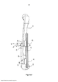
[0018] A Figura 1 é uma vista em perspectiva de uma primeira realização de um dispositivo ortopédico de acordo com a invenção;[0018] Figure 1 is a perspective view of a first embodiment of an orthopedic device according to the invention;
[0019] A Figura 1A mostra uma vista em perspectiva de um detalhe do dispositivo ortopédico da Figura 1;[0019] Figure 1A shows a perspective view of a detail of the orthopedic device of Figure 1;
[0020] A Figura 2 é uma vista lateral do dispositivo da Figura 1;[0020] Figure 2 is a side view of the device of Figure 1;
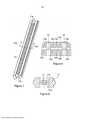
[0021] A Figura 3 é uma vista em perspectiva de um grampo de acordo com a invenção associado com o dispositivo ortopédico da Figura 1;[0021] Figure 3 is a perspective view of a clamp according to the invention associated with the orthopedic device of Figure 1;
[0022] A Figura 4 é uma vista em planta do grampo da Figura 3;[0022] Figure 4 is a plan view of the clamp of Figure 3;
[0023] A Figura 5 é uma vista em seção transversal tomada ao longo da linha V-V da Figura 4;[0023] Figure 5 is a cross-sectional view taken along the line V-V of Figure 4;
[0024] A Figura 6 é uma vista seccional transversal tomada ao longo da linha VI-VI da Figura 4;[0024] Figure 6 is a cross-sectional view taken along line VI-VI of Figure 4;
[0025] A Figura 7 é uma vista em perspectiva de um detalhe do dispositivo ortopédico da Figura 1;[0025] Figure 7 is a perspective view of a detail of the orthopedic device of Figure 1;
[0026] A Figura 8 é uma vista em seção transversal tomada ao longo da linha VIII-VIII da Figura 7;[0026] Figure 8 is a cross-sectional view taken along line VIII-VIII of Figure 7;
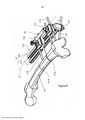
[0027] As Figuras 9 e 9A, respectivamente, são vistas em perspectiva de uma segunda realização de um dispositivo ortopédico de acordo com a invenção vista dos dois diferentes ângulos;[0027] Figures 9 and 9A, respectively, are seen in perspective of a second embodiment of an orthopedic device according to the invention seen from two different angles;
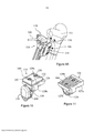
[0028] A Figura 10 é uma vista em perspectiva de um grampo do dispositivo ortopédico da Figura 9;[0028] Figure 10 is a perspective view of a clamp of the orthopedic device of Figure 9;
[0029] A Figura 11 é uma vista de um detalhe do grampo da Figura 10;[0029] Figure 11 is a view of a detail of the clamp of Figure 10;
[0030] A Figura 12 é uma vista em planta do grampo da Figura 10; e[0030] Figure 12 is a plan view of the clamp of Figure 10; and
[0031] A Figura 13 é uma vista em seção transversal tomada ao longo da linha XIII-XIII do grampo da Figura 12.[0031] Figure 13 is a cross-sectional view taken along line XIII-XIII of the clamp in Figure 12.
[0032] Com referência às Figuras, os números de referência (10, 110) indicam duas diferentes realizações de um dispositivo ortopédico a ser associado com o exterior de um osso, tal como, por exemplo, um fixador externo para osteossíntese de um osso fraturado ou um dispositivo ortopédico para correção de ossos deformados ou malformados ou para a reconstrução de ossos defeituosos. Tal dispositivo ortopédico (10, 110) é de um tipo compreendendo dois ou mais grampos montados em um trilho suporte e móvel em uma maneira incremental mais próximo a ou mais distante um do outro por meio de um dispositivo compressor/desviador.[0032] With reference to the Figures, the reference numbers (10, 110) indicate two different embodiments of an orthopedic device to be associated with the outside of a bone, such as, for example, an external fixator for osteosynthesis of a fractured bone or an orthopedic device for correcting deformed or malformed bones or for the reconstruction of defective bones. Such an orthopedic device (10, 110) is of a type comprising two or more clamps mounted on a support and movable rail in an incremental manner closer to or further away from each other by means of a compressor / diverter device.
[0033] No exemplo da Figura 1, o dispositivo ortopédico (10) é pretendido para corrigir deformações em um osso longo (11) tal como tíbia ou fêmur, em correspondência à zona central do osso, enquanto que o dispositivo ortopédico (110) da Figura 9 é pretendido corrigir as deformações em relação a metáfise de um fêmur (111) ou de uma tíbia.[0033] In the example of Figure 1, the orthopedic device (10) is intended to correct deformations in a long bone (11) such as tibia or femur, corresponding to the central area of the bone, while the orthopedic device (110) of Figure 9 is intended to correct the deformations in relation to the metaphysis of a femur (111) or a tibia.
[0034] Mais particularmente, como as figuras relativas acima mencionadas ilustram, a fim de permitir a correção de deformação, o osso (111) tem inutilmente sido submetido a osteotomia com a formação de duas extremidades (11a, 11b).[0034] More particularly, as the relative figures mentioned above illustrate, in order to allow the correction of deformation, the bone (111) has been uselessly subjected to osteotomy with the formation of two ends (11a, 11b).
[0035] O dispositivo ortopédico (10), contém um trilho (12), que no exemplo é feito de um material termoplástico reforçado de fibra, tal como o material comercialmente conhecido como “Orthtek” WF®, fibra de carbono na pultrusão da resina epóxi ou comercialmente conhecido como Peek CA30®, ou em uma liga de alumínio. O trilho (12) é estendido longitudinalmente ao longo de um determinado eixo central Y-Y, colocado lateral e paralelo ao osso (11).[0035] The orthopedic device (10), contains a rail (12), which in the example is made of a fiber reinforced thermoplastic material, such as the material commercially known as “Orthtek” WF®, carbon fiber in the resin pultrusion epoxy or commercially known as Peek CA30®, or in an aluminum alloy. The track (12) is extended longitudinally along a given central axis Y-Y, placed laterally and parallel to the bone (11).
[0036] No exemplo, como pode ser visto nas Figuras 7 e 8, o trilho (12) possui um perfil de T duplo e compreende dois sulcos opostos (15a, 15b) têm um formato de T. No centro de cada um dos sulcos (15a, 15b) há uma fenda longitudinal (13).[0036] In the example, as can be seen in Figures 7 and 8, the rail (12) has a double T profile and comprises two opposite grooves (15a, 15b) have a T shape. In the center of each of the grooves (15a, 15b) there is a longitudinal slit (13).
[0037] O dispositivo (10) além disso compreende pelo menos um primeiro grampo (24) que suporta um primeiro grupo de dois parafusos endósseos (16) inseridos na primeira extremidade do osso (11a) e um segundo grampo (18) que suporta um segundo grupo de parafusos endósseos (20) inseridos na segunda extremidade do osso (11b). Ambos os grampos são feitos de material termoplástico reforçado com fibra tal como o material comercialmente conhecido como Peek CA30® ou em uma liga de alumínio. Os parafusos endósseos (16, 20) são feitos de aço ou liga de titânio implantável.[0037] The device (10) furthermore comprises at least a first clamp (24) that supports a first group of two endosseous screws (16) inserted in the first end of the bone (11a) and a second clamp (18) that supports a second group of endosseous screws (20) inserted in the second end of the bone (11b). Both clamps are made of fiber-reinforced thermoplastic material such as the material commercially known as Peek CA30® or in an aluminum alloy. Endosseous screws (16, 20) are made of implantable titanium steel or alloy.
[0038] No exemplo, dois grampos (14, 18) são montados diretamente no trilho (12), em uma maneira removível e eles são idênticos.[0038] In the example, two clips (14, 18) are mounted directly on the rail (12), in a removable way and they are identical.
[0039] Cada grampo (14, 18), como ilustrado com referência ao grampo (18) nas Figuras 3, 4, 5 e 6 compreende um corpo de grampo com um mordente superior (23), que forma a tampa removível do grampo e um mordente inferior (24), que forma a base fixa do grampo, que fecha um contra outro por meio de dois parafusos de fixação (25, 26), feitos no exemplo de aço e/ou liga de titânio.[0039] Each clamp (14, 18), as illustrated with reference to the clamp (18) in Figures 3, 4, 5 and 6 comprises a clamp body with an upper jaw (23), which forms the removable clamp cover and a lower jaw (24), which forms the fixed base of the clamp, which closes against each other by means of two fixing screws (25, 26), made in the example of steel and / or titanium alloy.
[0040] Ambos os mordentes (23, 24) têm um formato retangular, com os respectivos lados mais curtos (23a, 23b, 24a, 24b) de uma extensão limitada, em torno de 40 mm no exemplo, e os respectivos lados mais longos (23c, 23d, 24c, 24d) de uma extensão limitada em tomo de 48mm no exemplo. Basicamente, no exemplo, o corpo do grampo possui uma extensão total máxima que não excede 50mm.[0040] Both jaws (23, 24) have a rectangular shape, with the respective shorter sides (23a, 23b, 24a, 24b) of a limited extent, around 40 mm in the example, and the respective longer sides (23c, 23d, 24c, 24d) of a limited length around 48mm in the example. Basically, in the example, the clamp body has a maximum total extension that does not exceed 50mm.
[0041] Mais particularmente, o mordente inferior (24) tem um perfil transversal de um formato de “T” com a cauda vertical (27) também tendo um perfil no formato de um T de cabeça para baixo, que é deslizavelmente inserido no sulco conjugado (15a) do trilho (12). O mordente inferior (24) é fixado em uma posição longitudinal específico no trilho (12) por meio de um parafuso de bloqueio (28) inserido na fenda longitudinal (13).[0041] More particularly, the lower jaw (24) has a cross-section of a "T" shape with the vertical tail (27) also having a T-shaped profile upside down, which is slidably inserted into the groove conjugate (15a) of the rail (12). The lower jaw (24) is fixed in a specific longitudinal position on the rail (12) by means of a locking screw (28) inserted in the longitudinal slot (13).
[0042] Outrossim, cada mordente (23, 24) compreende os respectivos sulcos guias transversais (29a, 29b) definindo sedes (29) para guias e alojar os parafusos endósseos (16, 20). No exemplo, os sulcos guias (29a, 29b) têm um perfil que está em formato de V para receber os parafusos endósseos de diferentes diâmetros; também no exemplo, os sulcos têm uma largura angular de 90° e recebem parafusos com um diâmetro de 5 ou 6mm.[0042] Furthermore, each jaw (23, 24) comprises the respective transverse guide grooves (29a, 29b) defining seats (29) for guides and housing the endosseous screws (16, 20). In the example, the guide grooves (29a, 29b) have a V-shaped profile to receive the endoscopic screws of different diameters; also in the example, the grooves have an angular width of 90 ° and receive screws with a diameter of 5 or 6mm.
[0043] O primeiro grampo (14) e o segundo grampo (18) são conectados por meio de um dispositivo compressor/desviador (58), que permite o deslocamento, em uma maneira incrementai, mais próximos ou mais distantes um do outro, dos dois grampos (14, 18) e, portanto, também das duas extremidades (11a, 11b). O compressor/desviador (58) é conectado aos grampos por meio de pinos de conexão (68) e (69) que são inseridos com pressão nos furos correspondentes (64) ou ocos, com uma forma cilíndrica e internamente lisos, nos grampos (14, 18).[0043] The first clamp (14) and the second clamp (18) are connected by means of a compressor / diverter device (58), which allows the displacement, in an incremental way, closer or more distant from each other, to the two clips (14, 18) and therefore also at both ends (11a, 11b). The compressor / diverter (58) is connected to the clamps by means of connecting pins (68) and (69) which are inserted with pressure in the corresponding holes (64) or hollow, with a cylindrical shape and internally smooth, in the clamps (14 , 18).
[0044] Na presente invenção pelo menos um dos dois grampos (14 ou 18) compreende dois furos (64) para a inserção de um dos dois pinos de conexão (68, 69) do compressor/desviador (58), o pino de conexão restante sendo inserido em um outro furo localizado no outro grampo (18 ou 14). Os dois furos do primeiro grampo e o furo remanescente do segundo grampo são alinhados ao longo de uma linha X que se estende paralela ao eixo longitudinal central Y-Y do trilho.[0044] In the present invention at least one of the two clamps (14 or 18) comprises two holes (64) for the insertion of one of the two connecting pins (68, 69) of the compressor / diverter (58), the connecting pin remainder being inserted into another hole located in the other clamp (18 or 14). The two holes in the first clamp and the remaining hole in the second clamp are aligned along a line X that extends parallel to the central longitudinal axis Y-Y of the rail.
[0045] Na realização preferida, cada grampo (14, 18) tem quatro furos para os pinos de conexão, alinhados dois em dois ao longo das respectivas linhas X que se estendem paralelas ao eixo longitudinal central Y-Y do trilho, colocados equidistantes deste eixo Y-Y.[0045] In the preferred embodiment, each clamp (14, 18) has four holes for the connecting pins, aligned two by two along the respective X lines that extend parallel to the central longitudinal axis YY of the rail, placed equidistant from this YY axis .
[0046] De acordo com uma realização da invenção, os furos (64) para a inserção odos pinos de conexão (68, 69) são colocados próximos um do outro e alinhados com os parafusos de fixação (25, 26) dos respectivos grampos (14, 18), ao longo de uma linha L que é paralela aos sulcos guias (29a, 29b), transversais com relação ao eixo central Y-Y do trilho, na realidade, no exemplo, formando um ângulo reto com o eixo Y-Y do trilho.[0046] According to an embodiment of the invention, the holes (64) for the insertion of the connecting pins (68, 69) are placed close to each other and aligned with the fixing screws (25, 26) of the respective clamps ( 14, 18), along a line L that is parallel to the guide grooves (29a, 29b), transversal with respect to the central axis YY of the rail, in reality, in the example, forming a right angle with the axis YY of the rail.
[0047] Cada grampo (14, 18) compreende quatro furos (64). Em particular, cada grampo (14, 18) compreende dois furos (64) alinhados nos lados opostos com relação ao primeiro parafuso de fixação (25) e dois furos (64) alinhados nos lados opostos com relação ao segundo parafuso de fixação (26). Existem, portanto, dois alinhamentos ou fileiras, cada qual incluindo dois furos (64) e um parafuso (25, 26) no centro.[0047] Each clamp (14, 18) comprises four holes (64). In particular, each clamp (14, 18) comprises two holes (64) aligned on opposite sides with respect to the first fixing screw (25) and two holes (64) aligned on opposite sides with respect to the second fixing screw (26) . There are, therefore, two alignments or rows, each including two holes (64) and a screw (25, 26) in the center.
[0048] De acordo com uma outra realização da invenção, os furos (64) estendem em profundidade tanto para o mordente superior (23) como para o mordente inferior (24) de cada grampo (14, 18). Basicamente, cada pino (68) do compressor/desviador (58) é inserido profundamente no corpo de cada grampo.[0048] According to another embodiment of the invention, the holes (64) extend in depth to both the upper jaw (23) and the lower jaw (24) of each clamp (14, 18). Basically, each pin (68) of the compressor / diverter (58) is inserted deep into the body of each clamp.
[0049] Consequentemente, segue-se que, por razões de tamanho, os furos (64) e os parafusos (25, 26) dos respectivos grampos (14, 18) são localizados nas partes do grampo (14, 18) que não são ocupados pelos sulcos guias (29a, 29b). Como é claramente ilustrado pela vista lateral da Figura 2 e sem seções transversais das Figuras 5 e 6, ao longo da seção transversal paralela ao lado longo (23c, 23d, 24c, 24d) do grampo (14, 18), os sulcos (29a, 29b) e as duas linhas L ou fileiras de parafusos (25, 26) e furos (64) alternam.[0049] Consequently, it follows that, for reasons of size, the holes (64) and screws (25, 26) of the respective clamps (14, 18) are located in the parts of the clamp (14, 18) that are not occupied by the guide grooves (29a, 29b). As is clearly illustrated by the side view of Figure 2 and without cross sections of Figures 5 and 6, along the cross section parallel to the long side (23c, 23d, 24c, 24d) of the clamp (14, 18), the grooves (29a , 29b) and the two rows L or rows of screws (25, 26) and holes (64) alternate.
[0050] De acordo com uma outra realização da invenção, cada grampo (14, 18) contém cinco sedes transversais (29) para parafusos ósseos, distribuídos como segue: um grupo central de três sedes (19) para parafusos ósseos e duas sedes laterais (29), cada qual em correspondência com uma zona lateral ou lado do relativo grampo (14m 18), em correspondência com a borda do lado curto (23a, 23b, 24a, 24b). Nesta configuração, cada fileira de parafusos (25, 26) e furos (64) é localizada seguinte a um grupo central de sedes (29), entre a última e uma respectiva sede lateral (29).[0050] According to another embodiment of the invention, each clamp (14, 18) contains five transverse seats (29) for bone screws, distributed as follows: a central group of three seats (19) for bone screws and two side seats (29), each in correspondence with a side zone or side of the relative clamp (14m 18), in correspondence with the short side edge (23a, 23b, 24a, 24b). In this configuration, each row of screws (25, 26) and holes (64) is located next to a central group of seats (29), between the last and a respective side seat (29).
[0051] Além disso, é possível observar como em todos os grampos, os quatros furos (64) acima descritos são colocados nos cantos de um retângulo, em proximidade aos quatro cantos do relativo grampo (14, 18).[0051] Furthermore, it is possible to observe how in all the clamps, the four holes (64) described above are placed in the corners of a rectangle, in proximity to the four corners of the relative clamp (14, 18).
[0052] Esta configuração permite maiores escolhas possíveis para a posição da inserção de um respectivo pino (68) do compressor/desviador (58).[0052] This configuration allows greater possible choices for the position of the insertion of a respective pin (68) of the compressor / diverter (58).
[0053] Na solução ilustrada, o compressor/desviador (58) compreende uma luva (59) que é tratada internamente, em correspondência à uma porção da extremidade (66) da qual um primeiro pino (68) é afixado, um eixo cilíndrico (63) ao qual um segundo pino (69) é afixado e um parafuso operador (64) com cabeça (60), alojado no eixo cilíndrico (63) e provido com uma contra-haste embutida e sextavada (61) cujo rosqueamento externo ajusta-se ao rosqueamento interno da luva (59). O compressor/desviador (58) além do mais contém um corpo anular (65) solidamente em rotação com a haste (61) do parafuso e colocado próximo do eixo cilíndrico (63), funcionando como um batente axial (12).[0053] In the illustrated solution, the compressor / diverter (58) comprises a sleeve (59) that is treated internally, corresponding to a portion of the end (66) to which a first pin (68) is attached, a cylindrical shaft ( 63) to which a second pin (69) is attached and an operator screw (64) with a head (60), housed in the cylindrical shaft (63) and provided with a built-in hexagonal countershaft (61) whose external threading to the internal threading of the sleeve (59). The compressor / diverter (58) furthermore contains an annular body (65) solidly rotating with the rod (61) of the screw and placed close to the cylindrical axis (63), functioning as an axial stop (12).
[0054] Uma vez os pinos de conexão (68, 69) tenham sido inseridos nos furos correspondentes (64) dos grampos (14, 18), basta girar o parafuso pela inserção de uma chave no hexágono contra embutido da cabeça (60) para se obter um deslocamento relativo dos dois grampos (14, 18) ao longo do trilho (12) e como um resultado, um deslocamento mais próximo a ou mais distante um do outro, das posições das extremidades do osso conectado aos mesmos.[0054] Once the connecting pins (68, 69) have been inserted into the corresponding holes (64) of the clamps (14, 18), simply turn the screw by inserting a key in the hexagon against the head's insert (60) to obtaining a relative displacement of the two clamps (14, 18) along the rail (12) and as a result, a displacement closer to or more distant from each other, from the positions of the ends of the bone connected to them.
[0055] Para permitir um usuário a controlar com segurança o deslocamento relativo dos grampos (14, 18), o compressor (58) compreende um elemento de botão (70), provido na borda de um ressalto (71) que é inserido em um entalhe correspondente (72) presente na superfície externa da cabeça (60).[0055] To enable a user to safely control the relative displacement of the clamps (14, 18), the compressor (58) comprises a button element (70), provided at the edge of a shoulder (71) which is inserted in a corresponding notch (72) present on the outer surface of the head (60).
[0056] Em particular, a cabeça (60) do parafuso tem quatro entalhes, escalonados em 90°. A fim de operar o parafuso (54), o elemento de botão (70) é empurrado a fim de desengatar a proeminência (71) do entalhe (71). O parafuso é então feito girar até o seu engate, por meio da pressão no elemento de botão (70), na proeminência (71) do entalhe seguinte ou um outro após aquele. Isto permite um usuário a conhecer que um quarto de volta ou uma meia volta do parafuso (54) tenha sido completado, que no exemplo corresponde a um deslocamento recíproco dos grampos de 0,25 mm ou 0,5mm, respectivamente.[0056] In particular, the screw head (60) has four notches, staggered by 90 °. In order to operate the screw (54), the button element (70) is pushed in order to disengage the prominence (71) from the notch (71). The screw is then turned until it engages, by pressing on the button element (70), on the prominence (71) of the next notch or another one after that. This allows a user to know that a quarter turn or a half turn of the screw (54) has been completed, which in the example corresponds to a reciprocal displacement of the clamps of 0.25 mm or 0.5 mm, respectively.
[0057] A vantagem principal do grampo e do dispositivo ortopédico relacionado de acordo com a presente invenção, reside no fato que o mesmo possui um número maior de sedes para parafusos transversais enquanto mantendo geralmente medições modestas. Na verdade, os parafusos de fixação lado a lado com os furos para a inserção dos pinos do compressor juntamente ocupam um reduzido espaço do corpo do grampo, deixando mais espaço disponível para os sulcos guias, e, assim para os parafusos endósseos. Nesta maneira, o grampo de acordo com a presente invenção tem dimensões que são juntamente reduzidas enquanto ao mesmo tempo mantendo o mesmo número de sulcos guias como um grampo conhecido do estado da técnica.[0057] The main advantage of the clamp and the related orthopedic device according to the present invention, lies in the fact that it has a greater number of seats for transverse screws while generally maintaining modest measurements. In fact, the fixing screws side by side with the holes for inserting the compressor pins together occupy a small space in the clamp body, leaving more space available for the guide grooves, and thus for the endosseous screws. In this way, the clamp according to the present invention has dimensions that are reduced together while at the same time maintaining the same number of guide grooves as a clamp known in the prior art.
[0058] Por exemplo, nas realizações ilustradas, o grampo possui cinco sedes transversais, que permitem ampla escolha na colocação recíproca de dois parafusos endósseos.[0058] For example, in the illustrated embodiments, the clamp has five transverse seats, which allow a wide choice in the reciprocal placement of two endosseous screws.
[0059] Uma outra vantagem reside no fato da distribuição específica de duas fileiras de furos, alternantes entre um grupo central de pelo menos três sulcos guias e dois sulcos guias laterais. Esta disposição permite outras possibilidades maiores na escolha da posição dos dois parafusos endósseos, por exemplo, ambos no grupo central ou um no grupo central e um no sulco lateral, etc.[0059] Another advantage is the specific distribution of two rows of holes, alternating between a central group of at least three guide grooves and two lateral guide grooves. This arrangement allows other greater possibilities when choosing the position of the two endosseous screws, for example, both in the central group or one in the central group and one in the lateral groove, etc.
[0060] Ainda, uma outra vantagem reside no fato que o grampo possui quatro furos para inserção dos pinos, que cria uma margem suficientemente larga de liberdade na escolha do arranjo mais útil do compressor/desviador com relação aos grampos e o trilho, quando o dispositivo ortopédico é montado em seguida no osso.[0060] Yet another advantage lies in the fact that the clamp has four holes for inserting the pins, which creates a sufficiently wide margin of freedom in choosing the most useful compressor / diverter arrangement in relation to the clamps and the rail, when the orthopedic device is then mounted on the bone.
[0061] Uma outra vantagem do grampo de acordo com a presente invenção reside no fato que é possível inserir os pinos do compressor/desviador profundamente em ambos os mordentes, que garante grande estabilidade na conexão com os relativos grampos.[0061] Another advantage of the clamp according to the present invention resides in the fact that it is possible to insert the pins of the compressor / diverter deeply in both jaws, which guarantees great stability in the connection with the relative clamps.
[0062] A seguir, com particular referência às Figuras 9-13, uma segunda realização de um dispositivo ortopédico de acordo com a presente invenção será ilustrada.[0062] In the following, with particular reference to Figures 9-13, a second embodiment of an orthopedic device according to the present invention will be illustrated.
[0063] O dispositivo ortopédico (110), contém pelo menos um primeiro grampo (114) e um segundo grampo (118), ambos montados em trilho (112) que possui a mesma estrutura e função que o trilho (12) previamente descrito.[0063] The orthopedic device (110), contains at least a first clamp (114) and a second clamp (118), both mounted on a rail (112) that has the same structure and function as the rail (12) previously described.
[0064] Mais particularmente, o segundo grampo (118) é o mesmo que o grampo (14, 18) da realização previamente descrita, suportando um grupo de parafusos endósseos (120) inseridos na extremidade próxima (11b) de um osso (111), ao passo que o grampo (114) constitui o parafuso principal de um grupo de grampos montados no trilho (112) em uma das suas extremidades que suportam parafusos endósseos (116, 122) inseridos em uma região metafisária do osso (111) (extremidade de osso distai 111a).[0064] More particularly, the second clamp (118) is the same as the clamp (14, 18) of the previously described embodiment, supporting a group of endosseous screws (120) inserted in the close end (11b) of a bone (111) , while the clamp (114) constitutes the main screw of a group of clamps mounted on the rail (112) at one of its ends that support endosseous screws (116, 122) inserted in a metaphyseal region of the bone (111) (end
[0065] Em particular, o grupo de grampos contém, em adição ao grampo principal (114), um grampo auxiliar (19) que é localizado no grampo principal (114) e que suporta os respectivos parafusos endósseos (122).[0065] In particular, the clamp group contains, in addition to the main clamp (114), an auxiliary clamp (19) which is located in the main clamp (114) and which supports the respective endosseous screws (122).
[0066] O grampo auxiliar (119) é colocado no grampo principal (114) em tal maneira que os respectivos parafusos endósseos (116, 122) são localizados nos planos P e P’, juntos, formando um ângulo reto.[0066] The auxiliary clamp (119) is placed in the main clamp (114) in such a way that the respective endosseous screws (116, 122) are located in the P and P 'planes, together, forming a right angle.
[0067] Em particular, o grampo principal (114) contém um mordente superior (123), que constitui a tampa removível do grampo e um mordente inferior (124), formando a base do grampo, fechado entre os mesmos por meio de dois parafusos de fixação (125, 126).[0067] In particular, the main clamp (114) contains an upper clamp (123), which constitutes the removable clamp cover and a lower clamp (124), forming the base of the clamp, closed between them by means of two screws fastening (125, 126).
[0068] O mordente superior (123) possui um formato retangular, similar ao mordente superior na realização previamente descrita, com lados curtos (123a, 123b) de 40 mm e lados longos (123c, 123d) de 48 mm.[0068] The upper jaw (123) has a rectangular shape, similar to the upper jaw in the previously described embodiment, with short sides (123a, 123b) of 40 mm and long sides (123c, 123d) of 48 mm.
[0069] O mordente inferior (124), justo como na realização previamente descrita, contém um corpo central (27a), tendo o formato de uma placa retangular de pequenas dimensões, no exemplo 53,7mm x 40 mm, com uma cauda vertical (131) que se projeta do corpo central (127a) e que é deslizavelmente inserida em um sulco (115) do trilho (112) que tem o formato de um T de cabeça para baixo, fixado em uma posição longitudinal específica por meio de um parafuso de bloqueio (133).[0069] The lower jaw (124), just as in the previously described embodiment, contains a central body (27a), having the shape of a small rectangular plate, in the example 53.7mm x 40 mm, with a vertical tail ( 131) which protrudes from the central body (127a) and which is slidably inserted into a groove (115) of the rail (112) that is shaped like an upside-down T, fixed in a specific longitudinal position by means of a screw locking (133).
[0070] Cada mordente (123, 124) além disso contém sulcos guias transversais (129a, 129b), respectivamente, definindo sedes (129) para guiar e alojar os parafusos endósseos (116).[0070] Each jaw (123, 124) furthermore contains transverse guide grooves (129a, 129b), respectively, defining seats (129) to guide and accommodate the endosseous screws (116).
[0071] O grampo principal (114) e o grampo (118) são conectados por meio de um dispositivo compressor/desviador (58), que permite o deslocamento incremental, mais próximo a ou mais distante de um do outro, dos dois grampos (114, 118) e, portanto, das duas extremidades de osso (111a, 111 b). O compressor/desviador (58) é conectado aos grampos por meio de pinos de conexão (68) do tipo previamente descrito, inserido por meio da pressão nos correspondentes furos (164) ou furos, de um formato cilíndrico e internamente liso, nos grampos (114, 118).[0071] The main clamp (114) and clamp (118) are connected by means of a compressor / diverter device (58), which allows the incremental displacement, closer to or more distant from each other, of the two clamps ( 114, 118) and, therefore, of the two bone ends (111a, 111 b). The compressor / diverter (58) is connected to the clamps by means of connecting pins (68) of the type previously described, inserted by means of pressure in the corresponding holes (164) or holes, of a cylindrical shape and internally smooth, in the clamps ( 114, 118).
[0072] De acordo com a presente invenção, pelo menos um dos dois grampos (114, 118) contém dois furos (164) para a inserção de um dos dois pinos de conexão (68, 69) do compressor/desviador (58), o pino de conexão restante sendo inserido em um outro furo no outro grampo (118, 114). Os dois furos do primeiro grampo e o furo restante do segundo grampo são alinhados ao longo de uma linha X’ que se estende paralelo ao eixo longitudinal central Y-Y do trilho (112).[0072] According to the present invention, at least one of the two clips (114, 118) contains two holes (164) for the insertion of one of the two connecting pins (68, 69) of the compressor / diverter (58), the remaining connecting pin being inserted into another hole in the other clamp (118, 114). The two holes in the first clamp and the remaining hole in the second clamp are aligned along a line X 'that extends parallel to the central longitudinal axis Y-Y of the rail (112).
[0073] No exemplo, o grampo (114) compreende quatro furos (164). Em particular, cada grampo (114) contém dois furos (164) alinhados, nos lados opostos, com o primeiro parafuso de fixação (125) e dois furos (164) alinhados, nos lados opostos, com o segundo parafuso de fixação (126). Existem, portanto, dois alinhamentos ou fileiras, cada qual incluindo dois furos (164) e um parafuso.[0073] In the example, the clamp (114) comprises four holes (164). In particular, each clamp (114) contains two holes (164) aligned, on opposite sides, with the first fixing screw (125) and two holes (164) aligned, on opposite sides, with the second fixing screw (126) . There are therefore two alignments or rows, each including two holes (164) and a screw.
[0074]Também nesta realização, os furos (164) estendem-se na profundidade através do mordente superior (123) e para o mordente inferior (124). Além do mais, também nesta realização, ao longo da seção transversal paralela ao lado longo do grampo (114) existem sulcos alternantes (129a, 129b) e duas fileiras de parafusos (125, 126) e furos (164); em particular, pode se notar um grupo de três sedes (129) no centro e uma sede (129) em cada lado do grampo (114).[0074] Also in this embodiment, the holes (164) extend in depth through the upper jaw (123) and to the lower jaw (124). Furthermore, also in this embodiment, along the cross section parallel to the long side of the clamp (114) there are alternating grooves (129a, 129b) and two rows of screws (125, 126) and holes (164); in particular, a group of three seats (129) in the center and a seat (129) on each side of the clamp (114) can be seen.
[0075] O mordente inferior (124) além disso compreende, em seguida a cauda vertical (131), um apêndice em formato de colar cilíndrico (127b), de eixo Z-Z, projetando-se do corpo central (127a) e pretendido para receber um apêndice cilíndrico correspondente (132) do grampo auxiliar (119), parcialmente visível na Figura 13, que é bloqueado por meio de um parafuso (130). O colar cilíndrico (127b) é provido com uma fenda (134) estende-se na superfície cilíndrica em um arco de um círculo que subtende um ângulo de cerca de 35° com o centro no eixo Z-Z. A conexão entre o apêndice (132) e o colar cilíndrico (127b) permite o movimento angular na placa P’ do grampo auxiliar (119), obtendo uma regulação da posição angular dos dois grampos (114, 119).[0075] The lower jaw (124) further comprises, then, the vertical tail (131), an appendix in the form of a cylindrical collar (127b), with ZZ axis, protruding from the central body (127a) and intended to receive a corresponding cylindrical appendix (132) of the auxiliary clamp (119), partially visible in Figure 13, which is blocked by means of a screw (130). The cylindrical collar (127b) is provided with a slit (134) extending on the cylindrical surface in an arc of a circle that subtends an angle of about 35 ° with the center on the Z-Z axis. The connection between the appendix (132) and the cylindrical collar (127b) allows the angular movement in the plate P 'of the auxiliary clamp (119), obtaining an adjustment of the angular position of the two clamps (114, 119).
[0076] O grampo auxiliar (119) por sua vez compreende um mordente inferior (138) que é feito de uma peça com o apêndice de conexão acima mencionado (132) e um mordente superior (137), que são fechados por meio de um parafuso (135).[0076] The auxiliary clamp (119) in turn comprises a lower jaw (138) which is made of one piece with the aforementioned connection appendix (132) and an upper jaw (137), which are closed by means of a screw (135).
[0077] Os parafusos endósseos (122) são alojados nas sedes transversais (139) entre os dois mordentes (137, 138); estas sedes são criadas pelas concavidades ou sulcos guias contrapostos.[0077] The endosseous screws (122) are housed in the transverse seats (139) between the two jaws (137, 138); these seats are created by the opposed concave or guide grooves.
[0078] Em particular, o mordente inferior (138) possui uma borda lateral (140) provida no lado de um primeiro sulco guia (141) que é colocado na proximidade a uma projeção da extremidade (148) do mordente superior (137), provido com um sulco guia oposto (149).[0078] In particular, the lower jaw (138) has a side edge (140) provided on the side of a first guide groove (141) which is placed in proximity to a projection of the end (148) of the upper jaw (137), provided with an opposite guide groove (149).
[0079] O mordente inferior (138) além disso compreende uma proeminência central (142) no lado de um sulco guia (143) que é colocado em proximidade a uma projeção (146) do mordente superior (137), provido no lado de um sulco guia contraposto.[0079] The lower jaw (138) furthermore comprises a central prominence (142) on the side of a guide groove (143) which is placed in proximity to a projection (146) of the upper jaw (137), provided on the side of a opposite guide groove.
[0080] Como pode ser observado nas Figuras, o parafuso de trava (135) passa através da borda (140), da projeção (148) e das proeminências (142, 146) paralelas ao plano P’. Graças a este arranjo é possível, por girar o parafuso de trava (135), regular a posição relativa dos dois mordentes no plano P’, que permite o ajuste de acordo com a necessidade da dimensão das sedes transversais (139) para os parafusos endósseos (122) acomodados aí, para acomodar parafusos ou outros elementos de fixação tubulares com diferentes dimensões, sem modificar a distância recíproca entre os mesmos.[0080] As can be seen in the Figures, the locking screw (135) passes through the edge (140), the projection (148) and the prominences (142, 146) parallel to the P 'plane. Thanks to this arrangement, it is possible, by turning the locking screw (135), to adjust the relative position of the two jaws on the P 'plane, which allows adjustment according to the size of the transverse seats (139) for the endosseous screws (122) accommodated there, to accommodate screws or other tubular fasteners with different dimensions, without changing the reciprocal distance between them.
[0081] A vantagem principal do grampo principal na última realização reside no fato que, como na realização prévia, apresenta-se grande número de sedes para os parafusos transversais, como dimensões que são geralmente modestas. Na verdade, os parafusos de fixação e os furos para a inserção dos pinos de conexão do compressor, sendo colocados lado a lado em uma linha, ocupam menos espaço no corpo do grampo, que deixa mais espaço para sulcos guias. Nesta maneira, o grampo de acordo com a presente invenção tem dimensões que são no conjunto reduzido ao mesmo tempo mantendo o mesmo número de sulcos guias como um grampo conhecido no estado da técnica.[0081] The main advantage of the main clamp in the last realization lies in the fact that, as in the previous realization, there are a large number of seats for the transverse screws, as dimensions that are generally modest. In fact, the fixing screws and holes for inserting the compressor connection pins, being placed side by side in a line, take up less space in the clamp body, which leaves more space for guide grooves. In this way, the clamp according to the present invention has dimensions that are reduced as a whole while maintaining the same number of guide grooves as a clamp known in the art.
[0082]Também, o grampo principal desta segunda realização possui cinco sedes transversais, que oferecem maiores possibilidades na escolha do posicionamento dos dois parafusos endósseos, em que as ditas sedes são de preferência distribuídas com um grupo central de pelo menos três sedes e duas sedes laterais.[0082] Also, the main clamp of this second embodiment has five transversal seats, which offer greater possibilities in the choice of the positioning of the two endosseous screws, in which said seats are preferably distributed with a central group of at least three seats and two seats side.
[0083] Uma outra vantagem do dispositivo ortopédico de acordo com esta segunda realização reside no fato que é possível ajustar não apenas a posição dos parafusos endósseos no grampo principal, mas também ajustar a posição dos parafusos endósseos suportados pelo grampo principal com relação aos parafusos endósseos suportados pelo grampo auxiliar.[0083] Another advantage of the orthopedic device according to this second embodiment lies in the fact that it is possible to adjust not only the position of the endoscopic screws in the main clamp, but also to adjust the position of the endoscopic screws supported by the main clamp in relation to the endosseous screws supported by the auxiliary clamp.
[0084] Graças a possibilidade do movimento angular do apêndice de conexão no colar cilíndrico, é na realidade possível ajustar a posição recíproca dos parafusos nos planos relativos, para satisfazer as necessidades anatômicas específicas do osso.[0084] Thanks to the possibility of the angular movement of the connection appendage in the cylindrical collar, it is actually possible to adjust the reciprocal position of the screws in the relative planes, to satisfy the specific anatomical needs of the bone.
[0085] Uma outra vantagem reside na possibilidade, como acima mencionada, de variar a dimensão das sedes transversais do grampo auxiliar.[0085] Another advantage lies in the possibility, as mentioned above, of varying the dimension of the transverse seats of the auxiliary clamp.
[0086] Obviamente numerosas modificações e variações podem ser aplicadas no grampo e no dispositivo ortopédico acima descrito por um técnico no assunto para satisfazer as necessidades contingentes e especificações, que estão em qualquer caso contidas no escopo de proteção da invenção como definido pelas seguintes reivindicações.[0086] Obviously numerous modifications and variations can be applied to the clamp and the orthopedic device described above by a person skilled in the art to satisfy contingent needs and specifications, which are in any case contained within the scope of protection of the invention as defined by the following claims.
Claims (15)
Applications Claiming Priority (3)
| Application Number | Priority Date | Filing Date | Title |
|---|---|---|---|
| ITBO2008A000548 | 2008-09-11 | ||
| ITBO2008A000548A IT1391222B1 (en) | 2008-09-11 | 2008-09-11 | ORTHOPEDIC DEVICE TO BE ASSOCIATED WITH A BONE |
| PCT/IB2009/006785 WO2010029406A1 (en) | 2008-09-11 | 2009-09-08 | Orthopaedic device to be associated with the outside of a bone |
Publications (3)
| Publication Number | Publication Date |
|---|---|
| BRPI0904847A2 BRPI0904847A2 (en) | 2015-06-30 |
| BRPI0904847B1 true BRPI0904847B1 (en) | 2020-07-28 |
| BRPI0904847B8 BRPI0904847B8 (en) | 2021-06-22 |
Family
ID=40565014
Family Applications (1)
| Application Number | Title | Priority Date | Filing Date |
|---|---|---|---|
| BRPI0904847A BRPI0904847B8 (en) | 2008-09-11 | 2009-09-08 | orthopedic device to be associated with the exterior of a bone |
Country Status (12)
| Country | Link |
|---|---|
| US (2) | US8182483B2 (en) |
| EP (1) | EP2185088B1 (en) |
| JP (1) | JP5519676B2 (en) |
| CN (1) | CN102209499B (en) |
| BR (1) | BRPI0904847B8 (en) |
| CA (1) | CA2736808C (en) |
| CO (1) | CO6382098A2 (en) |
| DK (1) | DK2185088T3 (en) |
| ES (1) | ES2389413T3 (en) |
| IT (1) | IT1391222B1 (en) |
| MX (1) | MX2011002560A (en) |
| WO (1) | WO2010029406A1 (en) |
Families Citing this family (30)
| Publication number | Priority date | Publication date | Assignee | Title |
|---|---|---|---|---|
| ES2471948T3 (en) * | 2006-10-13 | 2014-06-27 | Stryker Trauma Sa | Prevention of reuse of a medical device |
| IT1391711B1 (en) * | 2008-09-16 | 2012-01-27 | Orthofix Srl | ORTHOPEDIC DEVICE TO CORRECT LONG BONE DEFORMATIONS |
| ES2555582T3 (en) | 2009-05-15 | 2016-01-05 | Stryker Trauma Sa | Fixing flange |
| US8858555B2 (en) | 2009-10-05 | 2014-10-14 | Stryker Trauma Sa | Dynamic external fixator and methods for use |
| ES2446370T3 (en) | 2010-08-11 | 2014-03-07 | Stryker Trauma Sa | External fixing system |
| US11141196B2 (en) | 2010-08-11 | 2021-10-12 | Stryker European Operations Holdings Llc | External fixator system |
| US8945128B2 (en) | 2010-08-11 | 2015-02-03 | Stryker Trauma Sa | External fixator system |
| US8721566B2 (en) * | 2010-11-12 | 2014-05-13 | Robert A. Connor | Spinal motion measurement device |
| CN102641149B (en) * | 2011-02-21 | 2014-10-08 | 汤福刚 | Hip joint dislocation reset traction device |
| US8382758B1 (en) * | 2012-03-08 | 2013-02-26 | Mark Sommers | Method for aligning upper extremity bones and inserting guide device |
| US9101398B2 (en) | 2012-08-23 | 2015-08-11 | Stryker Trauma Sa | Bone transport external fixation frame |
| ITMI20130407A1 (en) * | 2013-03-18 | 2014-09-19 | Orthofix Srl | EXTERNAL FIXING DEVICE |
| US9962188B2 (en) | 2013-10-29 | 2018-05-08 | Cardinal Health 247. Inc. | External fixation system and methods of use |
| US10314618B2 (en) | 2014-07-25 | 2019-06-11 | The General Hospital Corporation | System and method for an external hip fixator |
| CN106137356A (en) * | 2015-04-22 | 2016-11-23 | 张韦 | A kind of orthopedic joint that withers of limb reconstruction can control exterior fixation bracket |
| CN104970871B (en) * | 2015-06-10 | 2017-08-11 | 哈尔滨精科奇科技有限责任公司 | Unilateral double-arm is adjustable two-way double dynamical Limb lengthening locking and pressurizing external fixator |
| EP3410964B1 (en) * | 2016-02-03 | 2020-03-18 | Citieffe S.r.L. | External orthopedic device |
| TWI561206B (en) * | 2016-04-01 | 2016-12-11 | E Da Hospital | A regulatable external fixator |
| US10010350B2 (en) | 2016-06-14 | 2018-07-03 | Stryker European Holdings I, Llc | Gear mechanisms for fixation frame struts |
| CN106037903A (en) * | 2016-08-22 | 2016-10-26 | 苏州益诺斯医疗科技有限公司 | Ankle joint support |
| CN106308902B (en) * | 2016-08-22 | 2020-05-01 | 苏州益诺斯医疗科技有限公司 | Bone extension support |
| US10874433B2 (en) | 2017-01-30 | 2020-12-29 | Stryker European Holdings I, Llc | Strut attachments for external fixation frame |
| IT201700093139A1 (en) * | 2017-08-11 | 2019-02-11 | Pier Luigi Caprioli | Multidirectional attachment device for external fixator in orthopedics. |
| CN107789043A (en) * | 2017-11-22 | 2018-03-13 | 广州新诚生物科技有限公司 | External fixation devices |
| RU2706135C1 (en) * | 2018-06-21 | 2019-11-14 | Дильшад Даларисович Шарафиев | Apparatus of sharafiev dilsad dalarisovich |
| CN108742816B (en) * | 2018-06-22 | 2021-02-26 | 吉林大学 | Internal marrow outer bone moving device |
| US11653951B2 (en) * | 2018-11-06 | 2023-05-23 | Ali Moradi | External orthopedic fixation device |
| JP7226786B2 (en) * | 2019-04-18 | 2023-02-21 | ネオメディカル株式会社 | external fixator |
| CN110680484B (en) * | 2019-10-28 | 2023-03-17 | 上海大学 | Clamping mechanism for robot-assisted lower limb fracture reduction operation |
| WO2022168057A1 (en) * | 2021-02-08 | 2022-08-11 | Nelson Saldanha Kiran Antony | System and devices for closed fracture reduction, deformity correction and fixation of bone |
Family Cites Families (20)
| Publication number | Priority date | Publication date | Assignee | Title |
|---|---|---|---|---|
| GB1582133A (en) * | 1976-04-30 | 1980-12-31 | Nat Res Dev | Orthopaedic fracture fixing apparatus |
| ES253459Y (en) * | 1978-11-10 | 1982-04-16 | EXTERNAL CLINICAL FIXER, OF HIGH STABILITY, TO REDUCE FRACTURES. | |
| IT1110581B (en) * | 1978-11-10 | 1985-12-23 | Istituto Ricerche Mediche I R | HIGH STABILITY EXTERNAL FIXER |
| US4502473A (en) * | 1981-08-06 | 1985-03-05 | National Research Development Corp. | Apparatus for external fixation of bone fractures |
| IT1181490B (en) * | 1984-12-18 | 1987-09-30 | Orthofix Srl | ORTHOPEDIC APPARATUS FOR EXTERNAL AXIAL FIXING, WITH A WIDE RANGE OF ADAPTABILITY |
| DE3701533A1 (en) * | 1987-01-21 | 1988-08-04 | Medi System Gmbh | OSTEOSYNTHESIS TOOLS |
| US4848327A (en) * | 1988-05-23 | 1989-07-18 | Perdue Kevin D | Apparatus and procedure for blind alignment of fasteners extended through transverse holes in an orthopedic locking nail |
| US5207676A (en) * | 1989-02-27 | 1993-05-04 | Jaquet Orthopedie S.A. | External fixator with controllable damping |
| CH679448A5 (en) * | 1989-02-27 | 1992-02-28 | Jaquet Orthopedie | |
| IT1234756B (en) * | 1989-03-17 | 1992-05-26 | Orthofix Srl | EXTERNAL FIXER PARTICULARLY SUITABLE TO BE APPLIED ON THE BASINS. |
| FR2683446A1 (en) * | 1991-11-08 | 1993-05-14 | Hardy Jean Marie | MODULAR EXTERNAL FIXER FOR IMMOBILIZING A FRACTURE FIREPLACE. |
| FR2705881A1 (en) * | 1993-06-01 | 1994-12-09 | Hardy Jean Marie | Support rail for filling in loss of bone substance |
| GB9325698D0 (en) * | 1993-12-15 | 1994-02-16 | Richardson James B | Patient-operated orthopedic device |
| US5743898A (en) * | 1995-05-12 | 1998-04-28 | Electro-Biology, Inc. | Method and apparatus for external fixation of small bones |
| IT1289103B1 (en) * | 1996-05-15 | 1998-09-25 | Orthofix Srl | COMPACT EXTERNAL FIXER |
| IT1293943B1 (en) * | 1997-02-14 | 1999-03-11 | Orthofix Srl | ORTHOPEDIC DEVICE FOR THE GRADUAL CORRECTION OF THE ARTS |
| NL1007426C1 (en) * | 1997-11-03 | 1999-05-04 | Gerrit Johannes Termaten | Device for mutually fixing bone parts. |
| US6678562B1 (en) * | 2000-01-12 | 2004-01-13 | Amei Technologies Inc. | Combined tissue/bone growth stimulator and external fixation device |
| US6565564B2 (en) * | 2000-12-14 | 2003-05-20 | Synthes U.S.A. | Multi-pin clamp and rod attachment |
| US7507240B2 (en) * | 2005-03-18 | 2009-03-24 | Ron Anthon Olsen | Adjustable splint for osteosynthesis |
-
2008
- 2008-09-11 IT ITBO2008A000548A patent/IT1391222B1/en active
-
2009
- 2009-09-08 EP EP09812749A patent/EP2185088B1/en active Active
- 2009-09-08 DK DK09812749.1T patent/DK2185088T3/en active
- 2009-09-08 US US12/676,648 patent/US8182483B2/en not_active Ceased
- 2009-09-08 CN CN200980144980XA patent/CN102209499B/en active Active
- 2009-09-08 CA CA2736808A patent/CA2736808C/en active Active
- 2009-09-08 JP JP2011526584A patent/JP5519676B2/en active Active
- 2009-09-08 MX MX2011002560A patent/MX2011002560A/en active IP Right Grant
- 2009-09-08 WO PCT/IB2009/006785 patent/WO2010029406A1/en active Application Filing
- 2009-09-08 BR BRPI0904847A patent/BRPI0904847B8/en active IP Right Grant
- 2009-09-08 ES ES09812749T patent/ES2389413T3/en active Active
- 2009-09-08 US US14/283,790 patent/USRE45888E1/en active Active
-
2011
- 2011-04-11 CO CO11044539A patent/CO6382098A2/en active IP Right Grant
Also Published As
| Publication number | Publication date |
|---|---|
| US20100222778A1 (en) | 2010-09-02 |
| IT1391222B1 (en) | 2011-12-01 |
| ES2389413T3 (en) | 2012-10-26 |
| MX2011002560A (en) | 2011-07-28 |
| CN102209499A (en) | 2011-10-05 |
| WO2010029406A1 (en) | 2010-03-18 |
| JP2012501776A (en) | 2012-01-26 |
| BRPI0904847A2 (en) | 2015-06-30 |
| US8182483B2 (en) | 2012-05-22 |
| CN102209499B (en) | 2013-10-23 |
| DK2185088T3 (en) | 2012-09-03 |
| JP5519676B2 (en) | 2014-06-11 |
| ITBO20080548A1 (en) | 2010-03-12 |
| CA2736808C (en) | 2016-12-13 |
| CO6382098A2 (en) | 2012-02-15 |
| BRPI0904847B8 (en) | 2021-06-22 |
| EP2185088A1 (en) | 2010-05-19 |
| CA2736808A1 (en) | 2010-03-18 |
| EP2185088B1 (en) | 2012-05-23 |
| USRE45888E1 (en) | 2016-02-16 |
Similar Documents
| Publication | Publication Date | Title |
|---|---|---|
| BRPI0904847B1 (en) | orthopedic device to be associated with the outside of a bone | |
| ES2655671T3 (en) | Fractured bone treatment system | |
| EP2938279B1 (en) | Alignment guide system | |
| US7785326B2 (en) | System for intramedullary rod fixation and method therefor | |
| ES2228444T3 (en) | IMPROVED EXTERNAL AXIAL FIXER. | |
| ES2457192T3 (en) | Short nail for the treatment of epiphysis fractures | |
| US9730711B2 (en) | Aiming device for targeted drilling of bone | |
| ES2606064T3 (en) | Instrument for orienting fixing screws | |
| US8460293B2 (en) | Intramedullary nail with shape memory elements for elongated bones | |
| ES2761802T3 (en) | Orthopedic device to correct long bone deformities | |
| BRPI0504202B1 (en) | endomedullary nail and device for the treatment of proximal femoral fractures | |
| JP2011522663A (en) | Intercortical nail inserted into fractured long bone | |
| BR112016024817B1 (en) | AMOUNT OF AN EXTERNAL FIXING AMOUNT HAVING A LONGITUDINAL AXIS DEFINED IN THE SAME AND AMOUNT ASSEMBLY METHOD | |
| BR112020026325A2 (en) | EXTERNAL FIXING CONNECTION ROD WITH FEMALE TIE | |
| JP6228309B2 (en) | Fixing device | |
| ES2226791T3 (en) | REDUCTION DEVICE FOR BEAR FRAGMENTS. | |
| EP3079606B1 (en) | Aiming device for targeted drilling of bone | |
| ES2386468B1 (en) | INTRAMEDULAR KEY, APPLICABLE FOR THE REPAIR OF OSEAS FRACTURES, WITH GUIDE DEVICE FOR DISTAL FIXATION | |
| AU2017203351B2 (en) | Fixation device | |
| BR112020016582A2 (en) | QUICK TAPE CLAMP FOR EXTERNAL FIXING SYSTEMS | |
| ES2651736A2 (en) | Guide for surgical intervention (Machine-translation by Google Translate, not legally binding) | |
| AU2014321173A1 (en) | Fixation device |
Legal Events
| Date | Code | Title | Description |
|---|---|---|---|
| B06A | Notification to applicant to reply to the report for non-patentability or inadequacy of the application [chapter 6.1 patent gazette] | ||
| B06A | Notification to applicant to reply to the report for non-patentability or inadequacy of the application [chapter 6.1 patent gazette] | ||
| B09A | Decision: intention to grant [chapter 9.1 patent gazette] | ||
| B16A | Patent or certificate of addition of invention granted |
Free format text: PRAZO DE VALIDADE: 10 (DEZ) ANOS CONTADOS A PARTIR DE 28/07/2020, OBSERVADAS AS CONDICOES LEGAIS. |
|
| B16C | Correction of notification of the grant |
Free format text: PRAZO DE VALIDADE: 20 (VINTE) ANOS CONTADOS A PARTIR DE 08/09/2009, OBSERVADAS AS CONDICOES LEGAIS. PATENTE CONCEDIDA CONFORME ADI 5.529/DF, QUE DETERMINA A ALTERACAO DO PRAZO DE CONCESSAO |