BRPI0808765B1 - METHOD AND APPARATUS FOR PROCESSING A SYNTHESIZED VOICE SIGNAL IN HIDING PACKAGE LOSS AND VOICE DECODER - Google Patents
METHOD AND APPARATUS FOR PROCESSING A SYNTHESIZED VOICE SIGNAL IN HIDING PACKAGE LOSS AND VOICE DECODER Download PDFInfo
- Publication number
- BRPI0808765B1 BRPI0808765B1 BRPI0808765-2A BRPI0808765A BRPI0808765B1 BR PI0808765 B1 BRPI0808765 B1 BR PI0808765B1 BR PI0808765 A BRPI0808765 A BR PI0808765A BR PI0808765 B1 BRPI0808765 B1 BR PI0808765B1
- Authority
- BR
- Brazil
- Prior art keywords
- voice signal
- signal
- tone
- subunit
- obtaining
- Prior art date
Links
Images


Classifications
-
- G—PHYSICS
- G10—MUSICAL INSTRUMENTS; ACOUSTICS
- G10L—SPEECH ANALYSIS OR SYNTHESIS; SPEECH RECOGNITION; SPEECH OR VOICE PROCESSING; SPEECH OR AUDIO CODING OR DECODING
- G10L19/00—Speech or audio signals analysis-synthesis techniques for redundancy reduction, e.g. in vocoders; Coding or decoding of speech or audio signals, using source filter models or psychoacoustic analysis
- G10L19/005—Correction of errors induced by the transmission channel, if related to the coding algorithm
-
- G—PHYSICS
- G10—MUSICAL INSTRUMENTS; ACOUSTICS
- G10L—SPEECH ANALYSIS OR SYNTHESIS; SPEECH RECOGNITION; SPEECH OR VOICE PROCESSING; SPEECH OR AUDIO CODING OR DECODING
- G10L19/00—Speech or audio signals analysis-synthesis techniques for redundancy reduction, e.g. in vocoders; Coding or decoding of speech or audio signals, using source filter models or psychoacoustic analysis
- G10L19/04—Speech or audio signals analysis-synthesis techniques for redundancy reduction, e.g. in vocoders; Coding or decoding of speech or audio signals, using source filter models or psychoacoustic analysis using predictive techniques
-
- G—PHYSICS
- G10—MUSICAL INSTRUMENTS; ACOUSTICS
- G10L—SPEECH ANALYSIS OR SYNTHESIS; SPEECH RECOGNITION; SPEECH OR VOICE PROCESSING; SPEECH OR AUDIO CODING OR DECODING
- G10L19/00—Speech or audio signals analysis-synthesis techniques for redundancy reduction, e.g. in vocoders; Coding or decoding of speech or audio signals, using source filter models or psychoacoustic analysis
- G10L19/02—Speech or audio signals analysis-synthesis techniques for redundancy reduction, e.g. in vocoders; Coding or decoding of speech or audio signals, using source filter models or psychoacoustic analysis using spectral analysis, e.g. transform vocoders or subband vocoders
- G10L19/0204—Speech or audio signals analysis-synthesis techniques for redundancy reduction, e.g. in vocoders; Coding or decoding of speech or audio signals, using source filter models or psychoacoustic analysis using spectral analysis, e.g. transform vocoders or subband vocoders using subband decomposition
-
- G—PHYSICS
- G10—MUSICAL INSTRUMENTS; ACOUSTICS
- G10L—SPEECH ANALYSIS OR SYNTHESIS; SPEECH RECOGNITION; SPEECH OR VOICE PROCESSING; SPEECH OR AUDIO CODING OR DECODING
- G10L19/00—Speech or audio signals analysis-synthesis techniques for redundancy reduction, e.g. in vocoders; Coding or decoding of speech or audio signals, using source filter models or psychoacoustic analysis
- G10L19/04—Speech or audio signals analysis-synthesis techniques for redundancy reduction, e.g. in vocoders; Coding or decoding of speech or audio signals, using source filter models or psychoacoustic analysis using predictive techniques
- G10L19/08—Determination or coding of the excitation function; Determination or coding of the long-term prediction parameters
- G10L19/097—Determination or coding of the excitation function; Determination or coding of the long-term prediction parameters using prototype waveform decomposition or prototype waveform interpolative [PWI] coders
Abstract
Description
[001] Este pedido reivindica a prioridade de Pedido Internacional N2_PCT/CN2008/070807, depositado em 25 de abril de 2008, que reivindica o benefício de prioridade do Pedido de Patente chinês N- 2007101696180, depositado em 5 de novembro de 2007. Os conteúdos dos pedidos identificados acima estão aqui incorporados a título de referência em sua totalidade.[001] This application claims the priority of International Application N2_PCT / CN2008 / 070807, filed on April 25, 2008, which claims the priority benefit of Chinese Patent Application N- 2007101696180, filed on November 5, 2007. The contents of the requests identified above are hereby incorporated by reference in their entirety.
[002] A presente invenção refere-se ao campo de processamento de sinal, e particularmente a um método e um aparelho para obter um fator de atenuação.[002] The present invention relates to the field of signal processing, and particularly to a method and apparatus for obtaining an attenuation factor.
[003] Exige-se que uma transmissão de dados de voz seja em tempo real e confiável em um sistema de comunicação de voz em tempo real, por exemplo, um sistema VoIP (Voz sobre IP). Devido às características não-confiáveis de um sistema de rede, um pacote de dados pode ser perdido ou não atingir o destino a tempo em um procedimento de transmissão de uma extremidade de envio para uma extremidade de recepção. Esses dois tipos de situações são considerados como perda de pacote de rede pela extremidade de recepção. É inevitável que a perda de pacote de rede ocorra. Entretanto, a perda de pacote de rede é um dos fatores mais importantes que influenciam a qualidade de fala da voz. Portanto, um método de ocultação de perda de pacote resistente é necessário para recuperar o pacote de dados perdido no sistema de comunicação em tempo real de modo que uma boa qualidade de fala ainda seja obtida sob a situação da perda de pacote de rede.[003] It is required that a voice data transmission be in real time and reliable in a real time voice communication system, for example, a VoIP (Voice over IP) system. Due to the unreliable characteristics of a network system, a data packet may be lost or not reach its destination in time in a procedure for transmitting from a sending end to a receiving end. These two types of situations are considered as loss of network packet by the receiving end. Network packet loss is inevitable. However, the loss of network packet is one of the most important factors that influence the speech quality of the voice. Therefore, a resistant packet loss hiding method is necessary to recover the lost data packet in the real-time communication system so that good speech quality is still obtained under the network packet loss situation.
[004] Na tecnologia de comunicação de voz em tempo real existente, na extremidade de envio, um codificador divide uma voz em banda larga em uma sub-banda alta e uma sub-banda baixa, e usa ADPCM (Modulação Adaptiva por Códigos de Pulsos Diferenciais) para codificar as duas sub-bandas respectivamente e enviá-las juntamente para a extremidade de recepção através da rede. Na extremidade de recepção, as duas sub-bandas são decodificadas respectivamente pelo decodificador ADPCM, e então o sinal final é sintetizado utilizando um filtro de síntese QMF (Filtro Espelhado em Quadratura).[004] In the existing real-time voice communication technology, at the sending end, an encoder divides a broadband voice into a high subband and a low subband, and uses ADPCM (Adaptive Pulse Code Modulation) Differentials) to encode the two subbands respectively and send them together to the receiving end via the network. At the receiving end, the two subbands are decoded respectively by the ADPCM decoder, and then the final signal is synthesized using a QMF synthesis filter (Mirrored Quadrature Filter).
[005] Diferentes métodos de Ocultação de Perda de Pacotes (PLC) são adotados para duas sub-bandas diferentes. Para um sinal de banda baixa, sob a situação sem perda de pacotes, um sinal de reconstrução não é alterado durante o FADING-CRUZADO. Sob a situação com perda de pacotes, para o primeiro quadro perdido, o sinal de histórico (o sinal de histórico é um sinal de voz antes do quadro perdido no presente documento de pedido) é analisado utilizando um indicador a curto prazo e um indicador a longo prazo, e informações de classificação de voz são extraídas. O sinal de quadro perdido é reconstruído utilizando uma LPC (codificação preditiva linear) baseada no método de repetição de tom, o indicador e as informações de classificação. O status de ADPCM também será atualizado de maneira síncrona até um bom quadro ser encontrado. Ademais, não só o sinal correspondente ao quadro perdido precisa ser gerado, como também uma seção de sinal adaptada para FADING-CRUZADO precisa ser gerada. Dessa maneira, uma vez que um quadro satisfatório é recebido, o FADING-CRUZADO é executado para processar o sinal de quadro satisfatório e a seção de sinal. Observa-se que esse tipo de FADING-CRUZADO ocorre apenas após a extremidade de recepção perder um quadro e receber o primeiro quadro satisfatório.[005] Different Packet Loss Concealment (PLC) methods are adopted for two different sub-bands. For a low band signal, under the situation without packet loss, a reconstruction signal is not altered during FADING-CROSS. Under the packet loss situation, for the first lost frame, the history signal (the history signal is a voice signal before the lost frame in this order document) is analyzed using a short-term indicator and an a long-term, and voice classification information is extracted. The lost frame signal is reconstructed using a LPC (linear predictive encoding) based on the tone repetition method, the indicator and the classification information. The ADPCM status will also be updated synchronously until a good frame is found. In addition, not only the signal corresponding to the lost frame needs to be generated, but also a signal section adapted for FADING-CRUZADO needs to be generated. In this way, once a satisfactory frame is received, FADING-CROSSED is performed to process the satisfactory frame signal and the signal section. It is observed that this type of FADING-CROSSED occurs only after the receiving end loses a frame and receives the first satisfactory frame.
[006] Durante o processo de realizar a presente invenção, o inventor percebeu pelo menos os seguintes problemas na técnica anterior: a energia do sinal sintetizado é controlada utilizando um fator de atenuação autoadaptativo estático na técnica anterior. Embora o fator de atenuação definido mude gradualmente, sua velocidade de atenuação, ou seja, o valor do fator de atenuação, é o mesmo com relação à mesma classificação de voz. Entretanto, as vozes humanas são variadas. Se o fator de atenuação não combinar com a característica de vozes humanas, ocorrerá um ruído desconfortável no sinal de reconstrução, particularmente no fim das vogais fixas. O fator de atenuação autoadaptativo estático pode não ser adaptado para a característica de vozes humanas diferentes.[006] During the process of carrying out the present invention, the inventor realized at least the following problems in the prior art: the energy of the synthesized signal is controlled using a static auto-adaptive attenuation factor in the prior art. Although the defined attenuation factor changes gradually, its attenuation speed, that is, the attenuation factor value, is the same with respect to the same voice classification. However, human voices are varied. If the attenuation factor does not match the characteristic of human voices, an uncomfortable noise will occur in the reconstruction signal, particularly at the end of the fixed vowels. The static self-adaptive attenuation factor may not be adapted to the characteristic of different human voices.
[007] A situação mostrada na figura 1 é tirada como um exemplo, onde To é o período de tom do sinal histórico. O sinal superior corresponde a um sinal original, ou seja, um diagrama esquemático em forma de onda sob a situação sem perda de pacotes. O sinal inferior com linha tracejada é um sinal sintetizado de acordo com a técnica anterior. Como pode ser observado a partir da figura, o sinal sintetizado não mantém a mesma velocidade de atenuação com o sinal original. Se houver muitas vezes a mesma repetição de tom, o sinal sintetizado irá produzir ruído musical óbvio de modo que a diferença entre a situação do sinal sintetizado e a situação desejada seja grande.[007] The situation shown in figure 1 is taken as an example, where To is the tone period of the historical signal. The upper signal corresponds to an original signal, that is, a schematic diagram in wave form under the situation without packet loss. The lower dashed line signal is a signal synthesized according to the prior art. As can be seen from the figure, the synthesized signal does not maintain the same attenuation speed as the original signal. If there is often the same tone repetition, the synthesized signal will produce obvious musical noise so that the difference between the situation of the synthesized signal and the desired situation is large.
[008] Uma modalidade da presente invenção proporciona um método e um aparelho para obter um fator de atenuação adaptado de modo a obter um fator de atenuação autoadaptativo e dinamicamente ajustável usado no processamento de sinal sintético.[008] One embodiment of the present invention provides a method and apparatus for obtaining an attenuation factor adapted to obtain a self-adaptive and dynamically adjustable attenuation factor used in synthetic signal processing.
[009] Uma modalidade da presente invenção proporciona um método para obter o fator de atenuação adaptado para processar o sinal sintetizado em ocultação de perda de pacotes, incluindo:[009] An embodiment of the present invention provides a method for obtaining the attenuation factor adapted to process the synthesized signal in hiding packet loss, including:
[0010] obter uma tendência de mudança de um sinal; e[0010] obtain a tendency to change a signal; and
[0011] obter um fator de atenuação de acordo com a tendência de mudança do sinal.[0011] obtain an attenuation factor according to the signal's changing tendency.
[0012] Uma modalidade da presente invenção também proporciona um aparelho para obter um fator de atenuação para processar um sinal sintetizado em ocultação de perda de pacotes. O aparelho para obter um fator de atenuação é configurado para:[0012] One embodiment of the present invention also provides an apparatus for obtaining an attenuation factor for processing a synthesized signal in hiding packet loss. The device to obtain an attenuation factor is configured to:
[0013] obter uma tendência de mudança de um sinal; e[0013] obtain a tendency to change a signal; and
[0014] obter um fator de atenuação de acordo com a tendência de mudança obtida.[0014] obtain an attenuation factor according to the obtained change trend.
[0015] Uma modalidade da presente invenção também proporciona um método e um aparelho para obter um fator de atenuação adaptado para realizar a transição suave dos dados de histórico para os últimos dados recebidos.[0015] An embodiment of the present invention also provides a method and apparatus for obtaining an attenuation factor adapted to smoothly transition the historical data to the last received data.
[0016] Para realizar o objetivo acima, uma modalidade da invenção proporciona um método para processamento de sinal, adaptado para processar um sinal sintetizado em ocultação de perda de pacotes, incluindo:[0016] To achieve the above objective, an embodiment of the invention provides a method for signal processing, adapted to process a synthesized signal in hiding packet loss, including:
[0017] obter uma tendência de mudança de um sinal;[0017] obtain a tendency to change a signal;
[0018] obter um fator de atenuação de acordo com a tendência de mudança do sinal; e[0018] obtain an attenuation factor according to the signal's changing tendency; and
[0019] obter um quadro perdido reconstruído após a atenuação de acordo com o fator de atenuação.[0019] obtain a lost frame reconstructed after the attenuation according to the attenuation factor.
[0020] Uma modalidade da presente invenção também proporciona um aparelho para processamento de sinal para processar um sinal sintetizado em ocultação de perda de pacotes, incluindo:[0020] One embodiment of the present invention also provides a signal processing apparatus for processing a synthesized signal in hiding packet loss, including:
[0021] o aparelho para obter um fator de atenuação para processar um sinal sintetizado em ocultação de perda de pacotes; e[0021] the device to obtain an attenuation factor to process a synthesized signal in hiding packet loss; and
[0022] uma unidade de reconstrução de quadro perdido adaptada para obter um quadro perdido reconstruído após a atenuação de acordo com o fator de atenuação.[0022] a lost frame reconstruction unit adapted to obtain a lost frame reconstructed after the attenuation according to the attenuation factor.
[0023] Uma modalidade da presente invenção também proporciona um decodificador de voz adaptado para decodificar o sinal de voz, inclusive uma unidade de decodificação de banda baixa, uma unidade de decodificação de banda alta e uma unidade de filtro espelhado em quadratura.[0023] One embodiment of the present invention also provides a speech decoder adapted to decode the speech signal, including a low band decoding unit, a high band decoding unit and a quadrature mirrored filter unit.
[0024] A unidade de decodificação de banda baixa é adaptada para decodificar um sinal de decodificação de banda baixa recebido, e compensar um sinal de baixa perdido.[0024] The low band decoding unit is adapted to decode a received low band decoding signal, and to compensate for a lost low signal.
[0025] A unidade de decodificação de banda alta é adaptada para decodificar um sinal de decodificação de banda alta, e compensar um sinal de banda alta perdido.[0025] The high band decoding unit is adapted to decode a high band decoding signal, and to compensate for a lost high band signal.
[0026] A unidade de filtro espelhado em quadratura é adaptada para obter um sinal de saída final sintetizando o sinal de decodificação de banda baixa e o sinal de decodificação de banda alta.[0026] The quadrature mirrored filter unit is adapted to obtain a final output signal synthesizing the low band decoding signal and the high band decoding signal.
[0027] A unidade de sinal de decodificação de banda baixa inclui uma subunidade de sinal de decodificação de banda baixa, uma LPC baseada na subunidade de repetição de tom e uma subunidade de "fading" cruzado.[0027] The low band decode signal unit includes a low band decode signal subunit, an LPC based on the tone repeat subunit and a cross fading subunit.
[0028] A subunidade de decodificação de banda baixa é adaptada para decodificar um sinal de fluxo de banda baixa recebido.[0028] The low band decoding subunit is adapted to decode a received low band flow signal.
[0029] A LPC baseada na subunidade de repetição de tom é adaptada para gerar um sinal sintetizado correspondente ao quadro perdido.[0029] The LPC based on the tone repetition subunit is adapted to generate a synthesized signal corresponding to the lost frame.
[0030] A subunidade de "fading" cruzado é adaptada para realizar o fading cruzado do sinal processado pela subunidade de decodificação de banda baixa e sinal sintetizado correspondente ao quadro perdido gerado pela LPC baseada na subunidade de repetição de tom.[0030] The cross-fading subunit is adapted to cross-fade the signal processed by the low-band decoding subunit and synthesized signal corresponding to the lost frame generated by the LPC based on the tone repetition subunit.
[0031] A LPC baseada na subunidade de repetição de tom inclui um módulo de análise e um módulo de processamento de sinal.[0031] The LPC based on the tone repetition subunit includes an analysis module and a signal processing module.
[0032] O módulo de análise é adaptado para analisar um sinal de histórico e gerar um sinal de quadro perdido reconstruído.[0032] The analysis module is adapted to analyze a historical signal and generate a reconstructed lost frame signal.
[0033] Uma modalidade da presente invenção proporciona ainda um produto de programa de computador, incluindo códigos de programa de computador que permitem que um computador execute qualquer etapa no método para obter o fator de atenuação adaptado para processar o sinal sintetizado em ocultação de perda de pacotes ou qualquer etapa no método de processamento de sinal para processar um sinal sintetizado em ocultação de perda de pacotes quando os códigos de programa de computador forem executados pelo computador.[0033] An embodiment of the present invention further provides a computer program product, including computer program codes that allow a computer to perform any step in the method to obtain the attenuation factor adapted to process the signal synthesized in hiding loss of packets or any step in the signal processing method to process a synthesized signal in hiding packet loss when computer program codes are executed by the computer.
[0034] Comparadas com a técnica anterior, as modalidades da presente invenção possuem as seguintes vantagens:[0034] Compared with the prior art, the modalities of the present invention have the following advantages:
[0035] um fator de atenuação autoadaptativo é ajustado de maneira dinâmica utilizando a tendência de mudança de um sinal histórico. A transição suave dos dados históricos para os últimos dados recebidos é realizada de modo que a velocidade de atenuação entre o sinal compensado e o sinal original seja mantida a mais constante possível para adaptar a característica de vozes humanas diferentes.[0035] a self-adaptive attenuation factor is dynamically adjusted using the trend of changing a historical signal. The smooth transition from historical data to the last received data is performed so that the attenuation speed between the compensated signal and the original signal is kept as constant as possible to adapt the characteristic of different human voices.
[0036] A figura 1 é um diagrama esquemático que ilustra o sinal original e o sinal sintetizado de acordo com a técnica anterior;[0036] Figure 1 is a schematic diagram that illustrates the original signal and the signal synthesized according to the prior art;
[0037] a figura 2 é um fluxograma que ilustra um método para obter um fator de atenuação de acordo com a Modalidade 1 da presente invenção;[0037] figure 2 is a flow chart illustrating a method for obtaining an attenuation factor in accordance with
[0038] a figura 3 é um diagrama esquemático que ilustra os princípios do codificador;[0038] figure 3 is a schematic diagram that illustrates the principles of the encoder;
[0039] a figura 4 é um diagrama esquemático que ilustra o módulo de uma LPC baseada na subunidade de repetição de tom da unidade de decodificação de banda baixa;[0039] figure 4 is a schematic diagram illustrating the module of an LPC based on the tone repetition subunit of the low band decoding unit;
[0040] a figura 5 é um diagrama esquemático que ilustra um sinal de saída após adotar o método de atenuação dinâmica de acordo com a Modalidade 1 da presente invenção;[0040] figure 5 is a schematic diagram that illustrates an output signal after adopting the dynamic attenuation method according to
[0041] as figuras 6A e 6B são diagramas esquemáticos que ilustram a estrutura do aparelho para obter um fator de atenuação de acordo com a Modalidade 2 da presente invenção;[0041] figures 6A and 6B are schematic diagrams that illustrate the structure of the apparatus to obtain an attenuation factor according to Modality 2 of the present invention;
[0042] a figura 7 é um diagrama esquemático que ilustra o cenário de aplicação do aparelho para obter um fator de atenuação de acordo com a Modalidade 2 da presente invenção;[0042] figure 7 is a schematic diagram that illustrates the application scenario of the device to obtain an attenuation factor according to Modality 2 of the present invention;
[0043] as figuras 8A e 8B são diagramas esquemáticos que ilustram a estrutura do aparelho para processamento de sinal de acordo com a Modalidade 3 da presente invenção;[0043] figures 8A and 8B are schematic diagrams illustrating the structure of the apparatus for signal processing according to Modality 3 of the present invention;
[0044] a figura 9 é um diagrama esquemático que ilustra o módulo do decodificador de voz de acordo com a Modalidade 4 da presente invenção;[0044] figure 9 is a schematic diagram illustrating the speech decoder module according to Modality 4 of the present invention;
[0045] a figura 10 é um diagrama esquemático que ilustra o módulo da unidade de decodificação de banda baixa no decodificador de voz de acordo com a Modalidade 4 da presente invenção;[0045] figure 10 is a schematic diagram illustrating the module of the low band decoding unit in the voice decoder according to Mode 4 of the present invention;
[0046] a figura 11 é um diagrama esquemático que ilustra o módulo da LPC baseada na subunidade de repetição de tom de acordo com a Modalidade 4 da presente invenção.[0046] figure 11 is a schematic diagram illustrating the LPC module based on the tone repetition subunit according to Modality 4 of the present invention.
[0047] A presente invenção será descrita em mais detalhes com referência aos desenhos e modalidades.[0047] The present invention will be described in more detail with reference to the drawings and modalities.
[0048] Proporciona-se um método para obter um fator de atenuação na Modalidade 1 da presente invenção, adaptado para processar o sinal sintetizado em ocultação de perda de pacotes, como mostrado na Figura 2, incluindo as seguintes etapas.[0048] A method is provided to obtain an attenuation factor in
[0049] Etapa s101, obtém-se uma tendência de mudança de um sinal;[0049] Step s101, a tendency to change a signal is obtained;
[0050] Especificamente, a tendência de mudança pode ser expressa nos seguintes parâmetros: (1) a razão da energia do último sinal periódico de tom para a energia do sinal periódico de tom anterior no sinal; (2) a razão da diferença entre o valor de amplitude máximo e o valor de amplitude mínimo do último sinal periódico de tom para a diferença entre o valor de amplitude máximo e o valor de amplitude mínimo do sinal periódico de tom anterior no sinal.[0050] Specifically, the trend of change can be expressed in the following parameters: (1) the ratio of the energy of the last periodic tone signal to the energy of the previous periodic tone signal in the signal; (2) the ratio of the difference between the maximum amplitude value and the minimum amplitude value of the last periodic tone signal to the difference between the maximum amplitude value and the minimum amplitude value of the previous periodic tone signal in the signal.
[0051] Etapa s102, obtém-se um fator de atenuação de acordo com a tendência de mudança.[0051] Step s102, an attenuation factor is obtained according to the trend of change.
[0052] O método de processamento específico da Modalidade 1 da presente invenção será descrito juntamente com o cenário de aplicação específico.[0052] The specific processing method of
[0053] Um método para obter um fator de atenuação que é adaptado para processar o sinal sintetizado em ocultação de perda de pacotes é proporcionado na Modalidade 1 da presente invenção.[0053] A method for obtaining an attenuation factor that is adapted to process the signal synthesized in hiding packet loss is provided in
[0054] Como mostrado na figura 3, diferentes métodos de PLC são adotados para duas sub-bandas diferentes. O método de PLC para a parte de banda baixa é mostrado como a parte 1 em um quadro tracejado na figura 3. Enquanto um quadro tracejado 2 na figura 3 é correspondente ao algoritmo de PLC da banda alta. Para um sinal de banda alta, zh^ é um sinal de banda alta finalmente produzido. Após obter o sinal de banda baixa zl(n>> e o sinal de banda alta zh(n), o QMF é executado para o sinal de banda baixa e o sinal de banda alta e um sinal de banda larga finalmente produzido yW é sintetizado.[0054] As shown in figure 3, different PLC methods are adopted for two different sub-bands. The PLC method for the low band part is shown as
[0055] Apenas o sinal de banda baixa é descrito em detalhes a seguir.[0055] Only the low band signal is described in detail below.
[0056] Sob a situação sem perda de quadro, o sinal


[0057] Sob a situação com perda de quadros, com relação ao primeiro quadro perdido, o sinal de histórico zl(n), n<o é analisado utilizando um indicador a curto prazo e um indicador a longo prazo, e informações de classificação de voz são extraídas. Adotando-se os indicadores acima e as informações de classificação, o sinal yl( n) é gerado utilizando um método de LPC baseada na repetição de tom. E o sinal de quadro perdido zl(n) é reconstruído como zl(n)=yl(n) n==0,... Ademais, o status de ADPCM também será atualizado de maneira síncrona até um quadro satisfatório ser obtido. Observa-se que não só o sinal correspondente ao quadro perdido precisa ser gerado, como também um sinal de 10ms , yl(n) n=L,... -1 adaptado para FADING-CRUZADO precisa ser gerado, o M é o número de pontos de amostragem de sinal que são incluídos no processo quando calcula-se a energia. Dessa maneira, uma vez que um quadro satisfatório é recebido, o FADING-CRUZADO é executado para xl( n)n=L,...-1,e yl(n), n=L... -1 observa-se que esse tipo de FADING-CRUZADO ocorre apenas após uma perda de quadro e quando a extremidade de recepção recebe os primeiros dados de quadro satisfatórios.[0057] Under the situation with loss of frames, with respect to the first lost frame, the historical signal zl (n), n <o is analyzed using a short-term indicator and a long-term indicator, and classification information of voice are extracted. Adopting the above indicators and classification information, the signal yl (n) is generated using an LPC method based on tone repetition. And the lost frame signal zl (n) is reconstructed as zl (n) = yl (n) n == 0, ... In addition, the ADPCM status will also be updated synchronously until a satisfactory frame is obtained. It is observed that not only the signal corresponding to the lost frame needs to be generated, but also a 10ms signal, yl (n) n = L, ... -1 adapted for FADING-CRUZADO needs to be generated, M is the number of signal sampling points that are included in the process when calculating the energy. In this way, once a satisfactory frame is received, FADING-CROSSED is performed for xl (n) n = L, ...- 1, and yl (n), n = L ... -1 that this type of FADING-CROSS occurs only after a loss of frame and when the receiving end receives the first satisfactory frame data.
[0058] Uma LPC baseada no método de repetição de tom na figura 3 é conforme mostrado na figura 4.[0058] An LPC based on the tone repetition method in figure 3 is as shown in figure 4.
[0059] Quando o quadro de dados for um quadro satisfatório, é armazenado em um buffer para uso no futuro.[0059] When the data frame is a satisfactory frame, it is stored in a buffer for use in the future.
[0060] Quando o primeiro quadro perdido for encontrado, o sinal final yl(n) precisa ser sintetizado em duas etapas. Na primeira, o sinal de histórico zl(n), n 297,...,1é analisado. Então, o sinal yl(n) n 0,..,L1 w = o,-”Ã-i é sintetizado de acordo com o resultado da análise, onde Léo comprimento de quadro do quadro de dados, ou seja, o número de pontos de amostragem correspondente a um quadro de sinal, Q é o comprimento do sinal que é necessário para analisar o sinal de histórico.[0060] When the first lost frame is found, the final signal yl (n) needs to be synthesized in two steps. In the first, the historical signal zl (n), n 297, ..., 1 is analyzed. Then, the signal yl (n) n 0, .., L1 w = o, - ”Ã-i is synthesized according to the result of the analysis, where Léo frame length of the data frame, that is, the number of sampling points corresponding to a signal frame, Q is the signal length that is required to analyze the signal history.
[0061] O módulo de LPC baseado na repetição de tom inclui especificamente as seguintes partes.[0061] The LPC module based on tone repetition specifically includes the following parts.
[0062] O filtro de análise a curto prazo A(z)e o filtro de síntese 1/ A(z) sã0 fjitros de Predição Linear (LP) baseados na ordem P . O filtro de análise de LP é definido como:
[0063] Através da análise de LP do sinal de histórico zl(n) n -Q,..,com o filtro A(z) um sinal residual e(n),n -Q,.., correspondente ao sinal de histórico zl(n) n -Q,..,é obtido: p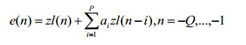
[0064] O sinal perdido é compensado por um método de repetição T de tom. Portanto, primeiramente, um período de tom 0 correspondente ao sinal de histórico zl(n),nQ,..precisa ser estimado. As etapas são as seguintes: O zl(n) é pré-processado para remover um ingrediente de baixa frequência inútil em uma análise de LTP (predição a longo prazo), e o período de tom T0 do zl(n) pode ser obtido pela análise de LTP. A classificação de voz é obtida apesar de combinar um módulo de classificação de sinal após obter o período de tom T°.[0064] The lost signal is compensated by a T tone repetition method. Therefore, first, a period of tone 0 corresponding to the historical signal zl (n), nQ, .. needs to be estimated. The steps are as follows: zl (n) is pre-processed to remove a useless low-frequency ingredient in an LTP (long-term prediction) analysis, and the z0 (n) T0 tone period can be obtained by LTP analysis. Voice classification is obtained despite combining a signal classification module after obtaining the T ° tone period.
[0065] As classificações de voz são conforme mostrado na tabela 1 a seguir:
[0066] Um módulo de repetição de tom é adaptado para estimar um sinal residual de LP e(n),n 0••• de um quadro perdido. Antes de a repetição de tom ser executada, se a classificação da voz não for VOICED, a seguinte fórmula é adotada para limitar a amplitude de uma amostra:
[0067] onde,
[0068] Se a classificação da voz for VOICED, o

[0069] Com relação a outras classificações de vozes, para evitar que a periodicidade do sinal gerado seja muito intensa (com relação ao sinal sem voz, se a periodicidade for muito intensa, pode-se ouvir algum ruído desconfortável como um ruído sonoro), o sinal residual e(n),n 0•••,L-1correspondente ao sinal perdido é gerado utilizando a seguinte fórmula:
[0070] Além de gerar o sinal residual correspondente ao quadro perdido, os sinais residuais ,
[0071] Após gerar o sinal residual correspondente ao quadro perdido e o FADING-CRUZADO, um sinal de quadro perdido de reconstrução

[0072] onde o sinal residual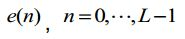
[0073] Também,
[0074] Para realizar uma suave transição de energia, antes de executar o QMF com o sinal de banda alta, o sinal de banda baixa também precisa realizar o FADING-CRUZADO, as regras são mostradas como a tabela a seguir: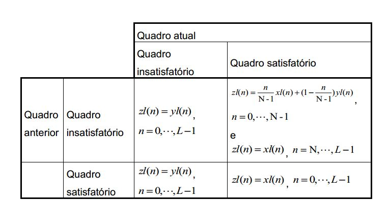
[0075] Na tabela acima, zl(n) é um sinal finalmente produzido correspondente ao quadro xl(n)atual; é o sinal do quadro satisfatório correspondente ao quadro atual; yl(n) é um sinal sintetizado correspondente ao mesmo tempo do quadro atual, onde Léo comprimento de quadro, N é o número de amostras que executam FADING-CRUZADO.[0075] In the table above, zl (n) is a signal finally produced corresponding to the current xl (n) frame; it is the sign of the satisfactory picture corresponding to the current picture; yl (n) is a synthesized signal corresponding to the current frame at the same time, where Léo frame length, N is the number of samples that execute FADING-CRUZADO.
[0076] Com relação a diferentes classificações de voz, a energia de sinal em
[0077] Em detalhes, no caso onde os últimos dois sinais periódicos de tom no sinal de histórico recebido é o sinal original como mostrado na figura 5, o fator de atenuação dinâmico autoadaptativo é dinamicamente ajustado de acordo com a tendência de mudança dos últimos dois períodos de tom no sinal de histórico. O método de ajuste detalhado inclui as seguintes etapas:[0077] In detail, in the case where the last two periodic tone signals in the received history signal is the original signal as shown in figure 5, the self-adaptive dynamic attenuation factor is dynamically adjusted according to the changing trend of the last two tone periods in the history signal. The detailed adjustment method includes the following steps:
[0078] Etapa s201, a tendência de mudança do sinal é obtida.[0078] Step s201, the trend of changing the signal is obtained.
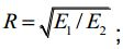
[0079] A tendência de mudança de sinal pode ser expressa pela razão da energia do último sinal de período de tom para a energia do sinal de período de tom anterior no sinal, ou seja, a energia Ei e E2 dos últimos dois sinais de períodos de tom no sinal de histórico, e a razão das duas energias é calculada.
[0080] E1é a energia do último sinal de período de tom, E 2 é a energia do sinal de período de tom anterior, e T0 e 0 periodo de tom correspondente ao sinal de histórico.[0080] E1 is the energy of the last tone period signal, E 2 is the energy of the previous tone period signal, and T0 and 0 tone period corresponding to the history signal.
[0081] Opcionalmente, a tendência de mudança de sinal pode ser expressa pela razão das diferenças de "pico-vale" dos últimos dois períodos de tom no sinal de histórico.
[0082] onde, é a diferença entre o valor de amplitude máximo o valor de amplitude mínimo do último sinal periódico de tom, é a diferença entre o valor de amplitude máximo e o valor de amplitude mínimo do sinal periódico de tom anterior, e a razão é calculada como:
[0083] Etapa s202, o sinal sintetizado é dinamicamente atenuado de acordo com a tendência de mudança obtida do sinal.[0083] Step s202, the synthesized signal is dynamically attenuated according to the change trend obtained from the signal.
[0084] A fórmula de cálculo é mostrada da seguinte maneira:
[0085] onde,

[0086] Sob a situação do fator de atenuação

[0087] Em particular, para evitar a situação onde o valor de amplitude correspondente a uma amostra é excedido sob a situação de R>1, o sinal sintetizado é dinamicamente atenuado utilizando a fórmula da etapa s202 na presente modalidade que leva em consideração apenas a situação de R <1.[0087] In particular, to avoid the situation where the amplitude value corresponding to a sample is exceeded under the situation of R> 1, the synthesized signal is dynamically attenuated using the formula of step s202 in the present modality that takes into account only the situation of R <1.
[0088] Em particular, para evitar a situação onde a velocidade de atenuação do sinal com menos energia é muito rápida, apenas sob a situação onde excede um certo valor limite, o sinal sintetizado é dinamicamente atenuado utilizando a fórmula da etapa s202 na presente modalidade.[0088] In particular, to avoid the situation where the attenuation speed of the signal with less energy is very fast, only under the situation where it exceeds a certain limit value, the synthesized signal is dynamically attenuated using the formula of step s202 in the present mode .
[0089] Em particular, para evitar que a velocidade de atenuação do sinal sintetizado seja muito rápida, especialmente sob a situação de perda de quadro contínua, um valor-limite superior é ajustado para o coeficiente de atenuação c. Quando C*(n+1) eXcede um valor-limite, o coeficiente de atenuação é ajustado como o valor limite superior.[0089] In particular, to prevent the attenuation speed of the synthesized signal from being too fast, especially under the situation of continuous loss of frame, an upper limit value is adjusted for the attenuation coefficient c. When C * (n + 1) eX yields a limit value, the attenuation coefficient is adjusted as the upper limit value.
[0090] Em particular, sob a situação de um ambiente de rede ruim e perda contínua de quadro, uma certa condição pode ser estabelecida para evitar uma velocidade de atenuação muito rápida. Por exemplo, pode-se levar em consideração que, quando o número de quadros perdidos exceder um número fixado, por exemplo, dois quadros; ou quando o sinal correspondente ao quadro perdido exceder um comprimento fixado, por exemplo, 20ms; ou em pelo menos uma das condições acima do coeficiente de atenuação atual
[0091] Por exemplo, sob a amostragem de situação a uma frequência de 8k e o comprimento de quadro de 40 amostras, o número de quadros perdidos pode ser ajustado como 4, e após o fator de atenuação
[0092] Hipoteticamente, é previsto que o coeficiente de atenuação atual é C e o valor de fator de atenuação é V, e o fator de atenuação V pode ser atenuado para 0 após as amostras vlc. Enquanto uma situação mais desejada é aquela onde o fator de atenuação V deve ser atenuado para 0 após as amostras

[0093] Como mostrado na figura 5, o sinal superior é o sinal original; o sinal intermediário é o sinal sintetizado. Como observado na figura, embora o sinal possua algum grau de atenuação, o sinal ainda permanece sonante intensivo. Se a duração for muito longa, o sinal pode ser mostrado como um ruído musical, especialmente no fim do som. O sinal inferior é o sinal após a utilização da atenuação dinâmica na modalidade da presente invenção, que pode ser muito similar ao sinal original.[0093] As shown in figure 5, the upper signal is the original signal; the intermediate signal is the synthesized signal. As seen in the figure, although the signal has some degree of attenuation, the signal still remains sound intensive. If the duration is too long, the signal can be shown as a musical noise, especially at the end of the sound. The lower signal is the signal after using dynamic attenuation in the mode of the present invention, which can be very similar to the original signal.
[0094] De acordo com o método proporcionado pela modalidade mencionada acima, o fator de atenuação autoadaptativo é dinamicamente ajustado utilizando a tendência de mudança do sinal de histórico, de modo que a transição suave dos dados de histórico para os últimos dados recebidos possa ser realizada. A velocidade de atenuação é mantida a mais constante possível entre o sinal compensado e o sinal original para adaptar a característica de vozes humanas variadas.[0094] According to the method provided by the aforementioned modality, the self-adaptive attenuation factor is dynamically adjusted using the trend of changing the historical signal, so that the smooth transition of the historical data to the last received data can be performed . The attenuation speed is kept as constant as possible between the compensated signal and the original signal to adapt the characteristic of varied human voices.
[0095] Um aparelho para obter um fator de atenuação é proporcionado na Modalidade 2 da presente invenção, adaptado para processar o sinal sintetizado em ocultação de perda de pacotes, incluindo:[0095] An apparatus for obtaining an attenuation factor is provided in Modality 2 of the present invention, adapted to process the synthesized signal in hiding packet loss, including:
[0096] uma unidade de obtenção de tendência de mudança 10, adaptada para obter uma tendência de mudança de um sinal;[0096] a changing
[0097] uma unidade de obtenção de fator de atenuação 20, adaptada para obter um fator de atenuação de acordo com a tendência de mudança obtidas pela unidade de obtenção de tendência de mudança 10.[0097] an
[0098] A unidade de obtenção de fator de atenuação 20 inclui adicionalmente: uma unidade de obtenção de coeficiente de atenuação 21, adaptada para gerar o coeficiente de atenuação de acordo com a tendência de mudança obtida pela unidade de obtenção de tendência de mudança 10; uma subunidade de obtenção de fator de atenuação 22, adaptada para obter um fator de atenuação de acordo com o coeficiente de atenuação gerado pela subunidade de obtenção de fator de atenuação 21. A unidade de obtenção de fator de atenuação 20 inclui ainda: uma subunidade de ajuste de coeficiente de atenuação 23, adaptada para ajustar o valor do coeficiente de atenuação obtido pela subunidade de obtenção de coeficiente de atenuação 21 a um determinado valor mediante determinadas condições que incluem pelo menos uma das seguintes características: se o valor do coeficiente de atenuação exceder um valor-limite superior; se houver a situação de perda contínua de quadro; e se a velocidade de atenuação for muito rápida.[0098] The
[0099] O método para obter um fator de atenuação na modalidade acima é o mesmo método para obter um fator de atenuação nas modalidades do método.[0099] The method to obtain an attenuation factor in the above modality is the same method to obtain an attenuation factor in the method modalities.
[00100] Em detalhes, a tendência de mudança obtida pela unidade de obtenção de tendência de mudança 10 pode ser expressa nos seguintes parâmetros: (1) a razão da energia do último sinal periódico de tom para a energia do sinal periódico de tom anterior no sinal; (2) a razão da diferença entre o valor de amplitude máximo e o valor de amplitude mínimo do último sinal periódico de tom para a diferença entre o valor de amplitude máximo e o valor de amplitude mínimo do sinal periódico de tom anterior no sinal.[00100] In detail, the trend of change obtained by the unit of obtaining trend of
[00101] Quando a tendência de mudança for expressa na razão de energia em (1), a estrutura do aparelho para obter um fator de atenuação é conforme mostrado na figura 6A. A unidade de obtenção de tendência de mudança 10 inclui ainda:[00101] When the trend of change is expressed in the energy ratio in (1), the structure of the device to obtain an attenuation factor is as shown in figure 6A. The
[00102] uma subunidade de obtenção de energia 11 adaptada para obter a energia do último sinal periódico de tom e a energia do sinal periódico de tom anterior;An
[00103] uma subunidade de obtenção de razão de energia 12 adaptada para obter a razão da energia do último sinal periódico de tom para a energia do sinal periódico de tom anterior obtido pela subunidade de obtenção de energia 11 e usa a razão para mostrar a tendência de mudança do sinal.[00103] an energy
[00104] Quando a tendência de mudança for expressa na razão de diferença de amplitude em (2), a estrutura do aparelho para obter um fator de atenuação é conforme mostrada na figura 6B. A unidade de obtenção de tendência de mudança 10 inclui ainda:[00104] When the trend of change is expressed in the amplitude difference ratio in (2), the structure of the device to obtain an attenuation factor is as shown in figure 6B. The
[00105] uma subunidade de obtenção de diferença de amplitude 13, adaptada para obter a diferença entre o valor de amplitude máximo e o valor de amplitude mínimo do último sinal periódico de tom, e a diferença entre o valor de amplitude máximo e o valor de amplitude mínimo do sinal periódico de tom anterior;[00105] a subunit of obtaining
[00106] uma subunidade de obtenção de razão de diferença de amplitude 14, adaptada para obter a razão da diferença entre o valor de amplitude máximo e o valor de amplitude mínimo do último sinal periódico de tom para a diferença entre o valor de amplitude máximo e o valor de amplitude mínimo do sinal periódico de tom anterior, e usar a razão para mostrar a tendência de mudança do sinal.[00106] a subunit of obtaining
[00107] Um diagrama esquemático que ilustra o cenário de aplicação do aparelho para obter um fator de atenuação de acordo com a Modalidade 2 da presente invenção é conforme mostrado na figura 7. O fator de atenuação autoadaptativo é dinamicamente ajustado utilizando a tendência de mudança do sinal de histórico.[00107] A schematic diagram that illustrates the application scenario of the device to obtain an attenuation factor according to Modality 2 of the present invention is as shown in figure 7. The self-adaptive attenuation factor is dynamically adjusted using the trend of change of the history sign.
[00108] Utilizando-se o aparelho proporcionado pela modalidade mencionada acima, o fator de atenuação autoadaptativo é dinamicamente ajustado utilizando a tendência de mudança do sinal de histórico de modo que a suave transição dos dados de histórico para os últimos dados recebidos seja realizada. A velocidade de atenuação é mantida a mais constante possível entre o sinal compensado e o sinal original para adaptar a característica de vozes humanas variadas.[00108] Using the device provided by the aforementioned modality, the self-adaptive attenuation factor is dynamically adjusted using the trend of changing the historical signal so that the smooth transition of the historical data to the last received data is carried out. The attenuation speed is kept as constant as possible between the compensated signal and the original signal to adapt the characteristic of varied human voices.
[00109] Proporciona-se um aparelho para processamento de sinal na Modalidade 3 da presente invenção, adaptado para processar o sinal sintetizado em ocultação de perda de pacotes, conforme mostrado na figura 8A e figura 8B. Baseado na Modalidade 2, adiciona-se uma unidade de reconstrução de quadro perdido 30 relacionada a uma unidade de obtenção de fator de atenuação. A unidade de reconstrução de quadro perdido 30 obtém um quadro reconstruído perdido após atenuação de acordo com o fator de atenuação obtido pela unidade de obtenção de fator de atenuação 20.[00109] An apparatus for signal processing in Modality 3 of the present invention, adapted to process the synthesized signal in concealment of packet loss, is provided, as shown in figure 8A and figure 8B. Based on Modality 2, a lost
[00110] Utilizando-se o aparelho proporcionado pela modalidade mencionada acima, o fator de atenuação autoadaptativo é dinamicamente ajustado utilizando a tendência de mudança do sinal de histórico, e um quadro perdido reconstruído após a atenuação ser obtida de acordo com o fator de atenuação, de modo que seja realizada uma transição suave dos dados de histórico para os últimos dados recebidos. A velocidade de atenuação é mantida a mais constante possível entre o sinal compensado e o sinal original para se adaptar à característica de vozes humanas variadas.[00110] Using the device provided by the aforementioned modality, the self-adaptive attenuation factor is dynamically adjusted using the trend of changing the historical signal, and a lost frame reconstructed after the attenuation is obtained according to the attenuation factor, so that a smooth transition from historical data to the last received data is carried out. The attenuation speed is kept as constant as possible between the compensated signal and the original signal to adapt to the characteristic of varied human voices.
[00111] Proporciona-se um decodificador de voz pela Modalidade 4 da presente invenção, como mostrado na figura 9. O decodificador de voz inclui: uma unidade de decodificação de banda alta 40 é adaptada para decodificar um sinal de decodificação de banda alta recebido e compensar um sinal de banda alta perdido; uma unidade de decodificação de banda baixa 50 é adaptada para decodificar um sinal de decodificação de banda baixa recebido e compensar um sinal de banda baixa perdido; e uma unidade de filtro espelhado em quadratura 60 é adaptada para obter um sinal de saída final sintetizando o sinal de decodificação de banda baixa e o sinal de decodificação de banda alta. A unidade de decodificação de banda alta 40 decodifica o sinal de fluxo de banda alta recebido pela extremidade de recepção, e sintetiza o sinal de banda alta perdido. A unidade de decodificação de banda baixa 50 decodifica o sinal de fluxo de banda baixa recebido pela extremidade de recepção e sintetiza o sinal de banda baixa perdido. A unidade de filtro espelhado em quadratura 60 obtém o sinal de decodificação final sintetizando o sinal de decodificação de banda baixa enviado pela unidade de decodificação de banda baixa 50 e o sinal de decodificação de banda alta enviado pela unidade de decodificação de banda alta 40.[00111] A voice decoder is provided by Mode 4 of the present invention, as shown in figure 9. The voice decoder includes: a high
[00112] Para a unidade de decodificação de banda baixa 50, como mostrado na figura 10, incluem-se as seguintes unidades. Uma LPC baseada na subunidade de repetição de tom 51 que é adaptada para gerar um sinal sintetizado correspondente ao quadro perdido, uma subunidade de decodificação de banda baixa 52 que é adaptada para decodificar um sinal de fluxo de banda baixa recebido, e uma subunidade de fading cruzado 53 que é adaptada para realizar o fading cruzado do sinal decodificado pela subunidade de decodificação de banda baixa e o sinal sintetizado correspondente ao quadro perdido gerado pela LPC baseada na subunidade de repetição de tom.[00112] For the low
[00113] A subunidade de decodificação de banda baixa 52 decodifica o sinal de fluxo de banda baixa recebido. A LPC baseada na subunidade de repetição de tom 51 gera o sinal sintetizado executando uma LPC no sinal de banda baixa perdido. E, por fim, a subunidade de fading cruzado 53 realiza o fading cruzado do sinal processado pela subunidade de decodificação de banda baixa 52 e o sinal sintetizado para obter um sinal de decodificação final após a compensação de quadro perdido.[00113] The low
[00114] A LPC baseada na subunidade de repetição de tom 51, como mostrado na figura 10, inclui ainda um módulo de análise 511 e um módulo de processamento de sinal 512. O módulo de análise 511 analisa um sinal de histórico, e gera um sinal de quadro perdido reconstruído; o módulo de processamento de sinal 512 obtém uma tendência de mudança de um sinal, e obtém um fator de atenuação de acordo com a tendência de mudança do sinal, e atenua o sinal de quadro perdido reconstruído, e obtém um quadro perdido reconstruído após a atenuação.[00114] The LPC based on the
[00115] O módulo de processamento de sinal 512 inclui ainda uma unidade de obtenção de fator de atenuação 5121 e uma unidade de reconstrução de quadro perdido 5122. A unidade de obtenção de fator de atenuação 5121 obtém uma tendência de mudança de um sinal, e obtém um fator de atenuação de acordo com a tendência de mudança; a unidade de reconstrução de quadro perdido 5122 atenua o sinal de quadro perdido reconstruído de acordo com o fator de atenuação, e obtém um quadro perdido reconstruído após a atenuação. O módulo de processamento de sinal 512 inclui duas estruturas correspondentes aos diagramas esquemáticos que ilustram a estrutura do aparelho para processamento de sinal na figura 8A e 8B, respectivamente.[00115] The
[00116] A unidade de obtenção de fator de atenuação 5121 inclui duas estruturas correspondentes aos diagramas esquemáticos que ilustram a estrutura do aparelho para obter um fator de atenuação na figura 6A e 6B, respectivamente. As funções específicas e meios de implementação dos módulos acima e unidades podem se referir ao conteúdo revelado nas modalidades do método. Detalhes desnecessários não serão repetidos aqui.[00116] The unit for obtaining
[00117] Através da descrição das modalidades mencionadas acima, os versados na técnica podem entender claramente que a presente invenção pode ser realizada dependendo do software mais a plataforma de hardware geral e necessária, e certamente também pode ser realizada por hardware. Entretanto, na maioria das situações, o formador é uma modalidade preferível. Baseado em tal entendimento, a essência ou a parte que contribui para a técnica anterior no esquema técnico da presente invenção pode ser expressa sob a forma de produto de software que é armazenado em um meio de armazenamento, e o produto de software inclui algumas instruções para instruir um dispositivo para executar as modalidades da presente invenção.[00117] Through the description of the modalities mentioned above, those skilled in the art can clearly understand that the present invention can be realized depending on the software plus the general and necessary hardware platform, and certainly can also be accomplished by hardware. However, in most situations, the trainer is a preferable modality. Based on such an understanding, the essence or part that contributes to the prior art in the technical scheme of the present invention can be expressed in the form of a software product that is stored in a storage medium, and the software product includes some instructions for instruct a device to perform the modalities of the present invention.
[00118] Apesar de a ilustração e descrição da presente descrição serem determinadas com referência às modalidades dessa, deve ser avaliado por versados na técnica que várias alterações em formas e detalhes podem ser feitas sem que se abandone o escopo da descrição.[00118] Although the illustration and description of the present description are determined with reference to the modalities of this, it should be evaluated by experts in the technique that various changes in shapes and details can be made without abandoning the scope of the description.
Claims (15)


Applications Claiming Priority (3)
| Application Number | Priority Date | Filing Date | Title |
|---|---|---|---|
| CN2007101696180A CN101207665B (en) | 2007-11-05 | 2007-11-05 | Method for obtaining attenuation factor |
| CN200710169618.0 | 2007-11-05 | ||
| PCT/CN2008/070807 WO2009059497A1 (en) | 2007-11-05 | 2008-04-25 | Method and apparatus for getting attenuation factor |
Publications (2)
| Publication Number | Publication Date |
|---|---|
| BRPI0808765A2 BRPI0808765A2 (en) | 2014-09-16 |
| BRPI0808765B1 true BRPI0808765B1 (en) | 2020-09-15 |
Family
ID=39567522
Family Applications (1)
| Application Number | Title | Priority Date | Filing Date |
|---|---|---|---|
| BRPI0808765-2A BRPI0808765B1 (en) | 2007-11-05 | 2008-04-25 | METHOD AND APPARATUS FOR PROCESSING A SYNTHESIZED VOICE SIGNAL IN HIDING PACKAGE LOSS AND VOICE DECODER |
Country Status (13)
| Country | Link |
|---|---|
| US (2) | US8320265B2 (en) |
| EP (2) | EP2056292B1 (en) |
| JP (2) | JP4824734B2 (en) |
| KR (1) | KR101168648B1 (en) |
| CN (4) | CN101207665B (en) |
| AT (2) | ATE484052T1 (en) |
| BR (1) | BRPI0808765B1 (en) |
| DE (3) | DE602008000668D1 (en) |
| DK (1) | DK2056292T3 (en) |
| ES (1) | ES2340975T3 (en) |
| HK (2) | HK1142713A1 (en) |
| PL (1) | PL2056292T3 (en) |
| WO (1) | WO2009059497A1 (en) |
Families Citing this family (19)
| Publication number | Priority date | Publication date | Assignee | Title |
|---|---|---|---|---|
| CN101325631B (en) * | 2007-06-14 | 2010-10-20 | 华为技术有限公司 | Method and apparatus for estimating tone cycle |
| CN100550712C (en) * | 2007-11-05 | 2009-10-14 | 华为技术有限公司 | A kind of signal processing method and processing unit |
| KR100998396B1 (en) * | 2008-03-20 | 2010-12-03 | 광주과학기술원 | Method And Apparatus for Concealing Packet Loss, And Apparatus for Transmitting and Receiving Speech Signal |
| CN101483042B (en) | 2008-03-20 | 2011-03-30 | 华为技术有限公司 | Noise generating method and noise generating apparatus |
| JP5150386B2 (en) * | 2008-06-26 | 2013-02-20 | 日本電信電話株式会社 | Electromagnetic noise diagnostic device, electromagnetic noise diagnostic system, and electromagnetic noise diagnostic method |
| JP5694745B2 (en) * | 2010-11-26 | 2015-04-01 | 株式会社Nttドコモ | Concealment signal generation apparatus, concealment signal generation method, and concealment signal generation program |
| EP2487350A1 (en) * | 2011-02-11 | 2012-08-15 | Siemens Aktiengesellschaft | Method for controlling a gas turbine |
| TWI610296B (en) | 2011-10-21 | 2018-01-01 | 三星電子股份有限公司 | Frame error concealment apparatus and audio decoding apparatus |
| US9330672B2 (en) | 2011-10-24 | 2016-05-03 | Zte Corporation | Frame loss compensation method and apparatus for voice frame signal |
| PL2922053T3 (en) | 2012-11-15 | 2019-11-29 | Ntt Docomo Inc | Audio coding device, audio coding method, audio coding program, audio decoding device, audio decoding method, and audio decoding program |
| ES2603827T3 (en) | 2013-02-05 | 2017-03-01 | Telefonaktiebolaget L M Ericsson (Publ) | Method and apparatus for controlling audio frame loss concealment |
| CN104299614B (en) * | 2013-07-16 | 2017-12-29 | 华为技术有限公司 | Coding/decoding method and decoding apparatus |
| CN104301064B (en) | 2013-07-16 | 2018-05-04 | 华为技术有限公司 | Handle the method and decoder of lost frames |
| CN103714820B (en) * | 2013-12-27 | 2017-01-11 | 广州华多网络科技有限公司 | Packet loss hiding method and device of parameter domain |
| US10035557B2 (en) * | 2014-06-10 | 2018-07-31 | Fu-Long Chang | Self-balancing vehicle frame |
| CN105225666B (en) | 2014-06-25 | 2016-12-28 | 华为技术有限公司 | The method and apparatus processing lost frames |
| US9978400B2 (en) * | 2015-06-11 | 2018-05-22 | Zte Corporation | Method and apparatus for frame loss concealment in transform domain |
| US10362269B2 (en) * | 2017-01-11 | 2019-07-23 | Ringcentral, Inc. | Systems and methods for determining one or more active speakers during an audio or video conference session |
| CN113496706B (en) * | 2020-03-19 | 2023-05-23 | 抖音视界有限公司 | Audio processing method, device, electronic equipment and storage medium |
Family Cites Families (41)
| Publication number | Priority date | Publication date | Assignee | Title |
|---|---|---|---|---|
| JP2654643B2 (en) | 1987-03-11 | 1997-09-17 | 東洋通信機株式会社 | Voice analysis method |
| JPH06130999A (en) | 1992-10-22 | 1994-05-13 | Oki Electric Ind Co Ltd | Code excitation linear predictive decoding device |
| WO1996000945A1 (en) | 1994-06-30 | 1996-01-11 | International Business Machines Corp. | Variable length data sequence matching method and apparatus |
| US5699485A (en) * | 1995-06-07 | 1997-12-16 | Lucent Technologies Inc. | Pitch delay modification during frame erasures |
| JP3095340B2 (en) | 1995-10-04 | 2000-10-03 | 松下電器産業株式会社 | Audio decoding device |
| TW326070B (en) | 1996-12-19 | 1998-02-01 | Holtek Microelectronics Inc | The estimation method of the impulse gain for coding vocoder |
| US6011795A (en) | 1997-03-20 | 2000-01-04 | Washington University | Method and apparatus for fast hierarchical address lookup using controlled expansion of prefixes |
| JP3567750B2 (en) | 1998-08-10 | 2004-09-22 | 株式会社日立製作所 | Compressed audio reproduction method and compressed audio reproduction device |
| US7423983B1 (en) | 1999-09-20 | 2008-09-09 | Broadcom Corporation | Voice and data exchange over a packet based network |
| JP2001228896A (en) | 2000-02-14 | 2001-08-24 | Iwatsu Electric Co Ltd | Substitution exchange method of lacking speech packet |
| US20070192863A1 (en) | 2005-07-01 | 2007-08-16 | Harsh Kapoor | Systems and methods for processing data flows |
| EP1199709A1 (en) | 2000-10-20 | 2002-04-24 | Telefonaktiebolaget Lm Ericsson | Error Concealment in relation to decoding of encoded acoustic signals |
| CN1311424C (en) | 2001-03-06 | 2007-04-18 | 株式会社Ntt都科摩 | Audio data interpolation apparatus and method, audio data-related information creation apparatus and method, audio data interpolation information transmission apparatus and method, program and |
| US6785687B2 (en) | 2001-06-04 | 2004-08-31 | Hewlett-Packard Development Company, L.P. | System for and method of efficient, expandable storage and retrieval of small datasets |
| US6816856B2 (en) | 2001-06-04 | 2004-11-09 | Hewlett-Packard Development Company, L.P. | System for and method of data compression in a valueless digital tree representing a bitset |
| US7143032B2 (en) | 2001-08-17 | 2006-11-28 | Broadcom Corporation | Method and system for an overlap-add technique for predictive decoding based on extrapolation of speech and ringinig waveform |
| US7711563B2 (en) | 2001-08-17 | 2010-05-04 | Broadcom Corporation | Method and system for frame erasure concealment for predictive speech coding based on extrapolation of speech waveform |
| EP1292036B1 (en) | 2001-08-23 | 2012-08-01 | Nippon Telegraph And Telephone Corporation | Digital signal decoding methods and apparatuses |
| CA2388439A1 (en) | 2002-05-31 | 2003-11-30 | Voiceage Corporation | A method and device for efficient frame erasure concealment in linear predictive based speech codecs |
| US20040064308A1 (en) | 2002-09-30 | 2004-04-01 | Intel Corporation | Method and apparatus for speech packet loss recovery |
| KR20030024721A (en) | 2003-01-28 | 2003-03-26 | 배명진 | A Soft Sound Method to Warmly Playback Sounds Recorded from Voice-Pen. |
| DE60327371D1 (en) * | 2003-01-30 | 2009-06-04 | Fujitsu Ltd | DEVICE AND METHOD FOR HIDING THE DISAPPEARANCE OF AUDIOPAKETS, RECEIVER AND AUDIO COMMUNICATION SYSTEM |
| US7415463B2 (en) | 2003-05-13 | 2008-08-19 | Cisco Technology, Inc. | Programming tree data structures and handling collisions while performing lookup operations |
| US7415472B2 (en) | 2003-05-13 | 2008-08-19 | Cisco Technology, Inc. | Comparison tree data structures of particular use in performing lookup operations |
| JP2005024756A (en) | 2003-06-30 | 2005-01-27 | Toshiba Corp | Decoding process circuit and mobile terminal device |
| US7302385B2 (en) | 2003-07-07 | 2007-11-27 | Electronics And Telecommunications Research Institute | Speech restoration system and method for concealing packet losses |
| US20050049853A1 (en) | 2003-09-01 | 2005-03-03 | Mi-Suk Lee | Frame loss concealment method and device for VoIP system |
| JP4365653B2 (en) | 2003-09-17 | 2009-11-18 | パナソニック株式会社 | Audio signal transmission apparatus, audio signal transmission system, and audio signal transmission method |
| KR100587953B1 (en) * | 2003-12-26 | 2006-06-08 | 한국전자통신연구원 | Packet loss concealment apparatus for high-band in split-band wideband speech codec, and system for decoding bit-stream using the same |
| JP4733939B2 (en) | 2004-01-08 | 2011-07-27 | パナソニック株式会社 | Signal decoding apparatus and signal decoding method |
| JP4744438B2 (en) | 2004-03-05 | 2011-08-10 | パナソニック株式会社 | Error concealment device and error concealment method |
| US7034675B2 (en) * | 2004-04-16 | 2006-04-25 | Robert Bosch Gmbh | Intrusion detection system including over-under passive infrared optics and a microwave transceiver |
| JP4345588B2 (en) * | 2004-06-24 | 2009-10-14 | 住友金属鉱山株式会社 | Rare earth-transition metal-nitrogen magnet powder, method for producing the same, and bonded magnet obtained |
| WO2006009074A1 (en) * | 2004-07-20 | 2006-01-26 | Matsushita Electric Industrial Co., Ltd. | Audio decoding device and compensation frame generation method |
| KR20060011417A (en) | 2004-07-30 | 2006-02-03 | 삼성전자주식회사 | Apparatus and method for controlling voice and video output |
| AU2006208529B2 (en) | 2005-01-31 | 2010-10-28 | Microsoft Technology Licensing, Llc | Method for weighted overlap-add |
| US8160868B2 (en) | 2005-03-14 | 2012-04-17 | Panasonic Corporation | Scalable decoder and scalable decoding method |
| US20070174047A1 (en) | 2005-10-18 | 2007-07-26 | Anderson Kyle D | Method and apparatus for resynchronizing packetized audio streams |
| KR100745683B1 (en) * | 2005-11-28 | 2007-08-02 | 한국전자통신연구원 | Method for packet error concealment using speech characteristic |
| CN1983909B (en) | 2006-06-08 | 2010-07-28 | 华为技术有限公司 | Method and device for hiding throw-away frame |
| CN101000768B (en) * | 2006-06-21 | 2010-12-08 | 北京工业大学 | Embedded speech coding decoding method and code-decode device |
-
2007
- 2007-11-05 CN CN2007101696180A patent/CN101207665B/en active Active
-
2008
- 2008-04-25 CN CN2008800010241A patent/CN101578657B/en active Active
- 2008-04-25 WO PCT/CN2008/070807 patent/WO2009059497A1/en active Application Filing
- 2008-04-25 CN CN201110092815.3A patent/CN102169692B/en active Active
- 2008-04-25 CN CN2012101846225A patent/CN102682777B/en active Active
- 2008-04-25 BR BRPI0808765-2A patent/BRPI0808765B1/en active IP Right Grant
- 2008-11-04 KR KR1020080108895A patent/KR101168648B1/en active IP Right Grant
- 2008-11-04 US US12/264,593 patent/US8320265B2/en active Active
- 2008-11-05 EP EP08168328A patent/EP2056292B1/en active Active
- 2008-11-05 DE DE602008000668T patent/DE602008000668D1/en active Active
- 2008-11-05 EP EP09178182A patent/EP2161719B1/en active Active
- 2008-11-05 DK DK08168328.6T patent/DK2056292T3/en active
- 2008-11-05 DE DE602008002938T patent/DE602008002938D1/en active Active
- 2008-11-05 PL PL08168328T patent/PL2056292T3/en unknown
- 2008-11-05 ES ES08168328T patent/ES2340975T3/en active Active
- 2008-11-05 AT AT09178182T patent/ATE484052T1/en not_active IP Right Cessation
- 2008-11-05 DE DE202008017752U patent/DE202008017752U1/en not_active Expired - Lifetime
- 2008-11-05 AT AT08168328T patent/ATE458241T1/en not_active IP Right Cessation
- 2008-11-05 JP JP2008284260A patent/JP4824734B2/en active Active
-
2009
- 2009-09-09 US US12/556,048 patent/US7957961B2/en active Active
-
2010
- 2010-03-17 JP JP2010060127A patent/JP5255585B2/en active Active
- 2010-07-27 HK HK10107180.3A patent/HK1142713A1/en unknown
-
2011
- 2011-09-22 HK HK11109983.7A patent/HK1155844A1/en unknown
Also Published As
Similar Documents
| Publication | Publication Date | Title |
|---|---|---|
| BRPI0808765B1 (en) | METHOD AND APPARATUS FOR PROCESSING A SYNTHESIZED VOICE SIGNAL IN HIDING PACKAGE LOSS AND VOICE DECODER | |
| RU2667029C2 (en) | Audio decoder and method for providing decoded audio information using error concealment modifying time domain excitation signal | |
| RU2678473C2 (en) | Audio decoder and method for providing decoded audio information using error concealment based on time domain excitation signal | |
| RU2675777C2 (en) | Device and method of improved signal fade out in different domains during error concealment | |
| JP4658596B2 (en) | Method and apparatus for efficient frame loss concealment in speech codec based on linear prediction | |
| KR101406742B1 (en) | Synthesis of lost blocks of a digital audio signal, with pitch period correction | |
| JP5849106B2 (en) | Apparatus and method for error concealment in low delay integrated speech and audio coding | |
| JP5624192B2 (en) | Audio coding system, audio decoder, audio coding method, and audio decoding method | |
| ES2644967T3 (en) | Adaptive bandwidth extension and device for it | |
| US8630864B2 (en) | Method for switching rate and bandwidth scalable audio decoding rate | |
| JP4698593B2 (en) | Speech decoding apparatus and speech decoding method | |
| US20110007827A1 (en) | Concealment of transmission error in a digital audio signal in a hierarchical decoding structure | |
| KR20190097312A (en) | Advanced quantizer | |
| JP5289319B2 (en) | Method, program, and apparatus for generating concealment frame (packet) | |
| US20090018823A1 (en) | Speech coding | |
| JP2013057792A (en) | Speech coding device and speech coding method | |
| JP2004078235A (en) | Voice encoder/decoder including unvoiced sound encoding, operated at a plurality of rates | |
| BR112015031177B1 (en) | EQUIPMENT AND METHOD THAT PERFORM A FADING OF AN MDCT SPECTRUM IN WHITE NOISE BEFORE APPLICATION OF FDNS |
Legal Events
| Date | Code | Title | Description |
|---|---|---|---|
| B15K | Others concerning applications: alteration of classification |
Free format text: PROCEDIMENTO AUTOMATICO DE RECLASSIFICACAO. AS CLASSIFICACOES IPC ANTERIORES ERAM: G10L 19/04; H04L 1/00; H04L 12/56. Ipc: G10L 19/005 (2013.01), G10L 19/02 (2013.01), G10L Ipc: G10L 19/005 (2013.01), G10L 19/02 (2013.01), G10L |
|
| B06F | Objections, documents and/or translations needed after an examination request according [chapter 6.6 patent gazette] | ||
| B06U | Preliminary requirement: requests with searches performed by other patent offices: procedure suspended [chapter 6.21 patent gazette] | ||
| B06A | Patent application procedure suspended [chapter 6.1 patent gazette] | ||
| B09A | Decision: intention to grant [chapter 9.1 patent gazette] | ||
| B16A | Patent or certificate of addition of invention granted [chapter 16.1 patent gazette] |
Free format text: PRAZO DE VALIDADE: 10 (DEZ) ANOS CONTADOS A PARTIR DE 15/09/2020, OBSERVADAS AS CONDICOES LEGAIS. |