BRPI0807909B1 - spray nozzles - Google Patents
spray nozzles Download PDFInfo
- Publication number
- BRPI0807909B1 BRPI0807909B1 BRPI0807909-9A BRPI0807909A BRPI0807909B1 BR PI0807909 B1 BRPI0807909 B1 BR PI0807909B1 BR PI0807909 A BRPI0807909 A BR PI0807909A BR PI0807909 B1 BRPI0807909 B1 BR PI0807909B1
- Authority
- BR
- Brazil
- Prior art keywords
- nozzle
- outlet
- fluid
- fact
- inlet
- Prior art date
Links
Images


Classifications
-
- B—PERFORMING OPERATIONS; TRANSPORTING
- B05—SPRAYING OR ATOMISING IN GENERAL; APPLYING FLUENT MATERIALS TO SURFACES, IN GENERAL
- B05B—SPRAYING APPARATUS; ATOMISING APPARATUS; NOZZLES
- B05B1/00—Nozzles, spray heads or other outlets, with or without auxiliary devices such as valves, heating means
- B05B1/14—Nozzles, spray heads or other outlets, with or without auxiliary devices such as valves, heating means with multiple outlet openings; with strainers in or outside the outlet opening
-
- B—PERFORMING OPERATIONS; TRANSPORTING
- B01—PHYSICAL OR CHEMICAL PROCESSES OR APPARATUS IN GENERAL
- B01J—CHEMICAL OR PHYSICAL PROCESSES, e.g. CATALYSIS OR COLLOID CHEMISTRY; THEIR RELEVANT APPARATUS
- B01J8/00—Chemical or physical processes in general, conducted in the presence of fluids and solid particles; Apparatus for such processes
- B01J8/18—Chemical or physical processes in general, conducted in the presence of fluids and solid particles; Apparatus for such processes with fluidised particles
- B01J8/24—Chemical or physical processes in general, conducted in the presence of fluids and solid particles; Apparatus for such processes with fluidised particles according to "fluidised-bed" technique
-
- B—PERFORMING OPERATIONS; TRANSPORTING
- B05—SPRAYING OR ATOMISING IN GENERAL; APPLYING FLUENT MATERIALS TO SURFACES, IN GENERAL
- B05B—SPRAYING APPARATUS; ATOMISING APPARATUS; NOZZLES
- B05B15/00—Details of spraying plant or spraying apparatus not otherwise provided for; Accessories
- B05B15/14—Arrangements for preventing or controlling structural damage to spraying apparatus or its outlets, e.g. for breaking at desired places; Arrangements for handling or replacing damaged parts
- B05B15/18—Arrangements for preventing or controlling structural damage to spraying apparatus or its outlets, e.g. for breaking at desired places; Arrangements for handling or replacing damaged parts for improving resistance to wear, e.g. inserts or coatings; for indicating wear; for handling or replacing worn parts
-
- B—PERFORMING OPERATIONS; TRANSPORTING
- B05—SPRAYING OR ATOMISING IN GENERAL; APPLYING FLUENT MATERIALS TO SURFACES, IN GENERAL
- B05B—SPRAYING APPARATUS; ATOMISING APPARATUS; NOZZLES
- B05B7/00—Spraying apparatus for discharge of liquids or other fluent materials from two or more sources, e.g. of liquid and air, of powder and gas
- B05B7/02—Spray pistols; Apparatus for discharge
- B05B7/08—Spray pistols; Apparatus for discharge with separate outlet orifices, e.g. to form parallel jets, i.e. the axis of the jets being parallel, to form intersecting jets, i.e. the axis of the jets converging but not necessarily intersecting at a point
- B05B7/0892—Spray pistols; Apparatus for discharge with separate outlet orifices, e.g. to form parallel jets, i.e. the axis of the jets being parallel, to form intersecting jets, i.e. the axis of the jets converging but not necessarily intersecting at a point the outlet orifices for jets constituted by a liquid or a mixture containing a liquid being disposed on a circle
-
- B—PERFORMING OPERATIONS; TRANSPORTING
- B01—PHYSICAL OR CHEMICAL PROCESSES OR APPARATUS IN GENERAL
- B01J—CHEMICAL OR PHYSICAL PROCESSES, e.g. CATALYSIS OR COLLOID CHEMISTRY; THEIR RELEVANT APPARATUS
- B01J2208/00—Processes carried out in the presence of solid particles; Reactors therefor
- B01J2208/00796—Details of the reactor or of the particulate material
- B01J2208/00893—Feeding means for the reactants
- B01J2208/00902—Nozzle-type feeding elements
Abstract
Um bocal de pulverização para descarregar pelo menos um fluido em um padrão de pulverização em uma corrente de fluido em um recipiente, tal como uma mistura atomizada de óleo e vapor em uma unidade de craqueamento catalítico fluí-dico, onde o bocal altera os padrões de fluxo da corrente de fluido nas proximidades do bocal para inibir erosão do bocal e manter o padrão de pulverização. O bocal compreende um elemento de entrada que define pelo menos um conduto de entrada e um elemento de saída em comunicação de fluido com o elemento de entrada. O elemento de saída inclui uma superfície exterior e uma pluralidade de ressaltos angularmente espaçados em relação mútua em torno de um eixo geométrico da saída, cada ressalto definindo uma abertura de saída em comunicação de fluido com pelo menos um conduto de entrada tendo um comprimento (L) e um diâmetro (D) e uma parede axialmente estendida, onde a parede axialmente estendida estende para fora por um comprimento (X) maior do que aproximadamente 0,32 cm (1/8polegada) em relação à superfície exterior e L/D é pelo menos aproximadamente 1/2.A spray nozzle to discharge at least one fluid in a spray pattern into a stream of fluid in a container, such as an atomized mixture of oil and steam in a fluidic catalytic cracking unit, where the nozzle changes the patterns of flow of fluid stream in the vicinity of the nozzle to inhibit nozzle erosion and maintain the spray pattern. The nozzle comprises an inlet element that defines at least one inlet conduit and an outlet element in fluid communication with the inlet element. The outlet element includes an outer surface and a plurality of angles spaced at an angle to each other around a geometric axis of the outlet, each shoulder defining an outlet opening in fluid communication with at least one inlet conduit having a length (L ) and a diameter (D) and an axially extended wall, where the axially extended wall extends outward by a length (X) greater than approximately 0.32 cm (1/8 inch) in relation to the outer surface and L / D is at least about 1/2.
Description
[001] Esse pedido reivindica prioridade ao pedido provisional US número 60/901.151, depositado em 13 de fevereiro de 2007, e se refere ao pedido US número 11/606.591, depositado em 29 de novembro de 2006, que reivindica prioridade ao pedido provisional US número 60/741.022, depositado em 29 de novembro de 2005, todos os quais são pelo presente incorporados a título de referência na íntegra como parte da presente revelação.[001] This order claims priority to US provisional order number 60 / 901,151, filed on February 13, 2007, and refers to US order number 11 / 606,591, filed on November 29, 2006, which claims priority to US provisional order number 60 / 741,022, filed on November 29, 2005, all of which are hereby incorporated by reference in full as part of this disclosure.
[002] A presente invenção refere-se a bocais de pulverização, e mais particularmente, a bocais de pulverização que descarregam pelo menos um fluido em uma pulverização atomizada e, mais particularmente, a bocais de pulverização que inibem erosão e mantêm um padrão de pulverização consistente quando a erosão ocorre.[002] The present invention relates to spray nozzles, and more particularly, to spray nozzles that discharge at least one fluid in an atomized spray and, more particularly, to spray nozzles that inhibit erosion and maintain a spray pattern consistent when erosion occurs.
[003] Craqueamento catalítico fluidizado (FCC) é um dos principais métodos de refinação utilizados na indústria de refinação de óleo. O processo FCC é empregado para craquear materiais que consistem essencialmente de hidrocarbonetos do tipo petróleo para produzir produtos como combustíveis para motores de combustão interna e óleos de aquecimento. O processo de craqueamento é normalmente executado em um conduto verticalmente orientado ou tubo ascendente incluindo um recipiente de reator, que faz parte de um sistema FCC. Durante o processo, partículas de catalisador quente em um estado arejado (fluidizado) são tipicamente introduzidas em uma porção inferior do tubo ascendente e induzidas a fluir para cima. Um insumo de hidrocarboneto é misturado com vapor para se tornar parcialmente fluidizado e injetado no fluxo de catalisador à medida que o catalisador se desloca através do tubo ascendente, que cria reações de craqueamento que rompem o insumo de hidrocarboneto em uma forma molecular mais simples (mais leve).[003] Fluid catalytic cracking (FCC) is one of the main refining methods used in the oil refining industry. The FCC process is used to crack materials that consist essentially of oil-type hydrocarbons to produce products such as fuels for internal combustion engines and heating oils. The cracking process is usually performed in a vertically oriented flue or riser including a reactor vessel, which is part of an FCC system. During the process, particles of hot catalyst in an aerated (fluidized) state are typically introduced into a lower portion of the riser and induced to flow upwards. A hydrocarbon input is mixed with steam to become partially fluidized and injected into the catalyst flow as the catalyst travels through the riser, which creates cracking reactions that break the hydrocarbon input into a simpler molecular form (more Light).
[004] Condições ótimas de craqueamento em um processo FCC exigem uma mistura substancialmente imediata e homogênea do catalisador e do insumo de hidrocarboneto. Tal mistura é difícil de se obter, entretanto, e regiões estratificadas de catalisador quente e insumo de hidrocarboneto frio aparecem tipicamente no fluxo de hidrocarboneto-catalisador. O craqueamento em excesso e craqueamento térmico das moléculas de hidrocarboneto ocorrem tipicamente nas áreas do fluxo, ricas em catalisador. Inversamente, craqueamento incompleto das moléculas de hidrocar-boneto ocorre, normalmente em regiões de fluxo ricas em hidrocarboneto. Esses fatores podem reduzir substancialmente o rendimento geral do processo FCC. Além disso, o craqueamento em excesso, craqueamento térmico e craqueamento incompleto têm efeitos colaterais indesejáveis como desativação do catalisador no tubo ascendente devido à disposição de coque, regeneração do catalisador no regenerador devido à combustão de ar e coque residual, e a produção de quantidades excessivas de produtos de reações gasosas na faixa de ebulição mais baixa, por exemplo, gases butano e propano.[004] Optimal cracking conditions in an FCC process require a substantially immediate and homogeneous mixture of the catalyst and the hydrocarbon input. Such a mixture is difficult to obtain, however, and stratified regions of hot catalyst and cold hydrocarbon input typically appear in the hydrocarbon-catalyst stream. Excessive cracking and thermal cracking of hydrocarbon molecules typically occur in the flow areas, rich in catalyst. Conversely, incomplete cracking of the hydrocarbon molecules occurs, usually in flow regions rich in hydrocarbons. These factors can substantially reduce the overall throughput of the FCC process. In addition, excessive cracking, thermal cracking and incomplete cracking have undesirable side effects such as deactivation of the catalyst in the riser due to the coke layout, catalyst regeneration in the regenerator due to combustion of air and residual coke, and the production of excessive quantities of products of gaseous reactions in the lowest boiling range, for example, butane and propane gases.
[005] Consequentemente, métodos eficazes para misturar o catalisador e o insumo de hidrocarboneto dentro do recipiente de reator são críticos para o processo de craqueamento, visto que a mistura adequada está se baseando após a manutenção de um padrão de pulverização constante do insumo de hidrocarboneto. O padrão de pulverização é obtido por limitar o fluxo através de passagens de fluxo moldadas cuidadosamente. Caso o formato das passagens mude, a razão de comprimento para diâmetro (L/D) das passagens de fluxo é alterada, o que por sua vez muda o padrão de pulverização. As mudanças na geometria e razão de L/D ocorrem mais frequentemente como resultado da erosão do material de bocal pelo catalisador em movimento do leito de fluido do tubo ascendente no qual o bocal é instalado.[005] Consequently, effective methods for mixing the catalyst and hydrocarbon input into the reactor vessel are critical to the cracking process, as the proper mixture is being based upon maintaining a constant spray pattern of the hydrocarbon input. . The spray pattern is achieved by limiting flow through carefully shaped flow passages. If the shape of the passages changes, the length-to-diameter ratio (L / D) of the flow passages is changed, which in turn changes the spray pattern. Changes in geometry and L / D ratio occur most often as a result of erosion of the nozzle material by the moving catalyst in the fluid bed of the riser in which the nozzle is installed.
[006] Para assegurar mistura adequada, bocais de pulverização foram idealizados que introduzem a mistura de vapor-hidrocarboneto no catalisador de fluxo ascendente; entretanto, os bocais atualmente disponíveis para uso em unidades FCC têm limitações significativas. Em primeiro lugar, os bocais podem gerar um padrão de pulverização irregular que reduz contato de líquido entre a mistura de vapor-hidrocarboneto e o catalisador, que por sua vez impede a mistura homogênea que leva a craqueamento em excesso, craqueamento térmico e/ou craqueamento incompleto das moléculas de hidrocarboneto. Em segundo lugar, os bocais são suscetíveis à erosão, o que altera significativa as passagens de fluxo interno do bocal que resultam em padrões de pulverização alterados, que por sua vez, pode reduzir a consistência e produção geral do rendimento do processo FCC. Limitações similares estão presentes em outros processos de refinação que utilizam bocais para introduzir fluidos em um recipiente de mistura, como processos de conversão bruta reduzida (RCC).[006] To ensure adequate mixing, spray nozzles have been designed that introduce the vapor-hydrocarbon mixture into the upstream catalyst; however, the nozzles currently available for use in FCC units have significant limitations. First, the nozzles can generate an irregular spray pattern that reduces liquid contact between the vapor-hydrocarbon mixture and the catalyst, which in turn prevents homogeneous mixing which leads to excess cracking, thermal cracking and / or cracking incomplete hydrocarbon molecules. Second, the nozzles are susceptible to erosion, which significantly alters the internal flow passages of the nozzle that result in altered spray patterns, which in turn can reduce the overall consistency and yield of the FCC process yield. Similar limitations are present in other refining processes that use nozzles to introduce fluids into a mixing vessel, such as reduced gross conversion (RCC) processes.
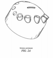
[007] Por exemplo, a patente US número 5.553.783 descreve um bocal dis-tribuidor de alimentação para um craqueador catalítico de fluido. Em ambientes altamente erosivos a superfície externa pode desgastar e o desgaste pode estender-se para o interior dos furos à medida que o exterior se desgasta (figuras 1A e 1B). Quando os furos mudam de formato por serem efetivamente encurtados, não mais podem orientar a pulverização como pretendido para manter o padrão de pulverização desejado, tipicamente uma pulverização de ventoinha plana. Com profundidade de erosão aumentada, a pulverização de ventoinha plana se torna definida de forma ruim e, eventualmente, o padrão de pulverização muda para um padrão de pulverização indesejável como padrão de cone estreito, que reduz significativamente a eficiência geral dos processos de RCC e FCC.[007] For example, US patent number 5,553,783 describes a feed distributor nozzle for a fluid catalytic cracker. In highly erosive environments the outer surface can wear and the wear can extend into the holes as the exterior wears out (figures 1A and 1B). When the holes change shape because they are effectively shortened, they can no longer orient the spray as intended to maintain the desired spray pattern, typically a flat fan spray. With increased erosion depth, flat fan spray becomes poorly defined and eventually the spray pattern changes to an undesirable spray pattern like a narrow cone pattern, which significantly reduces the overall efficiency of the RCC and FCC processes .
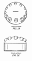
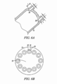
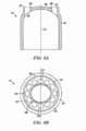
[008] Para a finalidade de orientar o padrão de pulverização, coberturas de bocal foram idealizadas que incorporam ressaltos externos (vide as figuras 2A-C, 3A-B e 4A-B); nenhuma dessas configurações são projetadas para manter as tolerâncias de L/D mínimas necessárias para padrões de pulverização consistentes quando utilizadas em aplicações que desgastam o bocal, como aplicações de FCC e RCC. Por exemplo, no bocal mostrado nas figuras 2A-C, os ressaltos têm razões L/D variáveis projetadas para orientar o padrão de pulverização mesmo com o padrão de furo inclinado do eixo geométrico, entretanto, as razões L/D variadas tornam impossível manter um padrão de pulverização consistente se o bocal desgastar. Além disso, nos bocais mostrados nas figuras 3A-B e 4A-B, os ressaltos incorporam uma configuração de “olho de gato” com passagens de fluxo tendo razões de L/D variadas, que são projetadas para fornecer padrões de pulverização de ventoinha plana pequena, individuais de diâmetros variáveis, porém como com o bocal anteriormente descrito, não é capaz de manter um padrão de pulverização consistente se o bocal desgastar.[008] For the purpose of orienting the spray pattern, nozzle covers were designed that incorporate external shoulders (see figures 2A-C, 3A-B and 4A-B); none of these configurations are designed to maintain the minimum L / D tolerances required for consistent spray patterns when used in nozzle wearing applications, such as FCC and RCC applications. For example, in the nozzle shown in figures 2A-C, the bosses have variable L / D ratios designed to guide the spray pattern even with the tilted hole pattern of the geometry axis, however, the varied L / D ratios make it impossible to maintain a consistent spray pattern if the nozzle wears. In addition, on the nozzles shown in figures 3A-B and 4A-B, the shoulders incorporate a “cat's eye” configuration with flow passages having varying L / D ratios, which are designed to provide flat fan spray patterns small, individual with variable diameters, but as with the nozzle described above, it is not able to maintain a consistent spray pattern if the nozzle wears out.
[009] Portanto, para melhorar o rendimento de FCC e outros processos de refinação e reduzir gastos de manutenção associados a substituições frequentes de bocal, há necessidade de um bocal de pulverização que gera um padrão de pulverização consistentemente plana para mistura homogênea aperfeiçoada, reduz zonas de pressão baixa à jusante e correntes parasitas para minimizar erosão de catalisador e maximizar a área de fluxo do catalisador, e é capaz de manter uma razão L/D mínima necessária à medida que o bocal desgasta para manter o padrão de pulverização desejado por um período prolongado de tempo.[009] Therefore, to improve the performance of FCC and other refining processes and reduce maintenance costs associated with frequent nozzle replacements, there is a need for a spray nozzle that generates a consistently flat spray pattern for improved homogeneous mixing, reduces zones low downstream pressure and eddy currents to minimize catalyst erosion and maximize catalyst flow area, and is capable of maintaining the minimum L / D ratio required as the nozzle wears to maintain the desired spray pattern for a period extended time.
[010] De acordo com um primeiro aspecto, a presente invenção é dirigida a um bocal de pulverização para descarregar pelo menos um fluido em um padrão de pulverização em uma corrente de fluido em um recipiente, onde o bocal altera os padrões de fluxo da corrente de fluido nas proximidades do bocal para inibir a erosão do bocal e manter o padrão de pulverização. O bocal compreende uma entrada que define pelo menos um conduto de entrada, uma saída em comunicação de fluido com a entrada, a saída definindo uma superfície exterior. Além disso, a saída define uma pluralidade de ressaltos angularmente espaçados em relação mútua em torno de um eixo geométrico da saída, cada ressalto definindo uma abertura de saída em comunicação de fluido com pelo menos um conduto de entrada e uma parede axialmente estendida, onde a parede axialmente estendida estende para fora por um comprimento (X) maior do que aproximadamente 0,32 cm (1/8 polegada) em relação à superfície exterior. O conduto de entrada tem comprimento (L) e um diâmetro (D) e L/D é pelo menos aproximadamente 1/2.[010] According to a first aspect, the present invention is directed to a spray nozzle to discharge at least one fluid in a spray pattern into a fluid stream in a container, where the nozzle changes the flow patterns of the stream of fluid in the vicinity of the nozzle to inhibit nozzle erosion and maintain the spray pattern. The nozzle comprises an inlet that defines at least one inlet conduit, an outlet in fluid communication with the inlet, the outlet defining an outer surface. In addition, the outlet defines a plurality of angularly spaced shoulders in mutual relation around a geometric axis of the outlet, each shoulder defining an outlet opening in fluid communication with at least one inlet conduit and an axially extended wall, where the axially extended wall extends outward by a length (X) greater than approximately 0.32 cm (1/8 inch) from the outer surface. The inlet conduit has length (L) and diameter (D) and L / D is at least approximately 1/2.
[011] De acordo com outro aspecto, a presente invenção é dirigida a um bocal para descarregar mistura atomizada de um líquido e um gás em pelo menos um entre um recipiente de craqueamento catalítico fluídico e um recipiente de conversão bruta reduzida. O bocal compreende uma entrada que define pelo menos um conduto de entrada, uma saída em comunicação de fluido com a entrada, a saída definindo uma superfície exterior. Além disso, a saída inclui uma pluralidade de ressaltos angularmente espaçados em relação mútua em torno de um eixo geométrico da saída, cada ressalto definindo uma abertura de saída em comunicação de fluido com pelo menos um conduto de entrada e uma parede estendida axialmente, onde a parede estendida axialmente estende para fora por um comprimento (X) maior do que aproximadamente 0,32 cm (1/8 polegada) em relação à superfície exterior. O conduto de entrada tem comprimento (L) e um diâmetro (D) e L/D é pelo menos aproximadamente 1/2.[011] According to another aspect, the present invention is directed to a nozzle for discharging atomized mixture of a liquid and a gas into at least one between a fluidic catalytic cracking container and a reduced crude conversion container. The nozzle comprises an inlet that defines at least one inlet conduit, an outlet in fluid communication with the inlet, the outlet defining an outer surface. In addition, the outlet includes a plurality of angles spaced at an angle to each other around a geometric axis of the outlet, each shoulder defining an outlet opening in fluid communication with at least one inlet conduit and an axially extended wall, where the The axially extended wall extends outward by a length (X) greater than approximately 0.32 cm (1/8 inch) from the outer surface. The inlet conduit has length (L) and diameter (D) and L / D is at least approximately 1/2.
[012] De acordo com outro aspecto, a presente invenção, aproximadamente todos os eixos geométricos de fluxo das aberturas de saída são orientados em direção a um alvo dentro do recipiente para atomizar e orientar uma mistura dos primeiro e segundo fluidos em um padrão de pulverização que flui em uma direção através do alvo. Além disso, o alvo é substancialmente localizado em um plano se estendendo na direção de fluxo do padrão de pulverização.[012] In accordance with another aspect, the present invention, approximately all flow geometrical axes of the outlet openings are oriented towards a target within the container to atomize and orient a mixture of the first and second fluids in a spray pattern that flows in one direction through the target. In addition, the target is substantially located on a plane extending in the direction of flow of the spray pattern.
[013] De acordo com outro aspecto, a presente invenção é dirigida a um bo-cal para descarregar mistura atomizada de um líquido e um gás em pelo menos um entre um recipiente de craqueamento catalítico fluídico e um recipiente de conversão bruta reduzida. O bocal compreende uma entrada que define pelo menos um conduto de entrada, uma saída em comunicação de fluido com a entrada, a saída definindo uma superfície exterior. Além disso, o bocal inclui uma pluralidade de elementos de ressalto, cada elemento de ressalto adaptado em uma abertura respectiva e definindo uma abertura de saída em comunicação de fluido com pelo menos um conduto de entrada tendo um comprimento (L) e um diâmetro (D) e uma parede axialmente estendida, onde a parede axialmente estendida estende para fora por um comprimento (X) maior do que aproximadamente 0,32 cm (1/8polegada) em relação à superfície exterior e L/D é pelo menos aproximadamente 1/2.[013] According to another aspect, the present invention is directed to a nozzle for discharging atomized mixture of a liquid and a gas in at least one between a fluidic catalytic cracking container and a reduced crude conversion container. The nozzle comprises an inlet that defines at least one inlet conduit, an outlet in fluid communication with the inlet, the outlet defining an outer surface. In addition, the nozzle includes a plurality of shoulder elements, each shoulder element adapted to a respective opening and defining an outlet opening in fluid communication with at least one inlet conduit having a length (L) and a diameter (D ) and an axially extended wall, where the axially extended wall extends outward by a length (X) greater than approximately 0.32 cm (1/8 inch) from the outer surface and L / D is at least approximately 1/2 .
[014] De acordo ainda com outro aspecto, a presente invenção é dirigida a um bocal de pulverização para descarregar pelo menos um fluido em um padrão de pulverização em uma corrente de fluido em um recipiente. O bocal compreende um primeiro meio para receber pelo menos um fluido, um segundo meio em comunicação de fluido com o primeiro meio para emitir pelo menos um fluido em um padrão de pulverização a partir do mesmo, e um terceiro meio em comunicação de fluido com pelo menos um dos primeiro e segundo meios para alterar padrões de fluxo da corrente de fluido nas proximidades do bocal para inibir erosão do bocal e manter o padrão de pulverização. Em uma tal modalidade, o primeiro meio é um elemento de entrada que define pelo menos um conduto de entrada para receber pelo menos um fluido, o segundo meio um elemento de saída em comunicação de fluido com o elemento de entrada, o elemento de saída definindo uma superfície exterior e uma pluralidade de aberturas angularmente espaçadas em relação mútua em torno de um eixo geométrico da saída, e o terceiro meio é uma pluralidade de elementos de ressalto, cada elemento de ressalto adaptado em uma abertura respectiva e definindo uma abertura de saída tendo um comprimento (L) e um diâmetro (D) e uma parede axialmente estendida, onde a parede axialmente estendida estende para fora por um comprimento (X) maior do que aproximadamente 0,32 cm (1/8polegada) em relação à superfície exterior e L/D é pelo menos aproximadamente 1/2.[014] In accordance with yet another aspect, the present invention is directed to a spray nozzle to discharge at least one fluid in a spray pattern into a fluid stream in a container. The nozzle comprises a first means for receiving at least one fluid, a second means in fluid communication with the first means for emitting at least one fluid in a spray pattern from it, and a third means in fluid communication with hair. at least one of the first and second means to alter flow patterns of the fluid stream in the vicinity of the nozzle to inhibit erosion of the nozzle and maintain the spray pattern. In such an embodiment, the first means is an input element that defines at least one inlet conduit to receive at least one fluid, the second means an output element in fluid communication with the input element, the output element defining an outer surface and a plurality of angularly spaced openings in mutual relation around a geometric axis of the outlet, and the third means is a plurality of boss elements, each boss element adapted in a respective opening and defining an outlet opening having a length (L) and a diameter (D) and an axially extended wall, where the axially extended wall extends outward by a length (X) greater than approximately 0.32 cm (1/8 inch) from the outer surface, and L / D is at least approximately 1/2.
[015] De acordo ainda com outro aspecto, a presente invenção é dirigida a um bocal de pulverização para descarregar pelo menos um fluido em um padrão de pulverização em uma corrente de fluido em um recipiente, onde o bocal altera os padrões de fluxo da corrente de fluido nas proximidades do bocal para inibir erosão do bocal e manter o padrão de pulverização. O bocal compreende uma entrada que define pelo menos um conduto de entrada, e uma saída em comunicação de fluido com a entrada, a saída definindo uma superfície exterior e dois elementos de parede formando um único ressalto contínuo em torno de um eixo geométrico central da saída. O ressalto contínuo definindo uma pluralidade de aberturas de saída tendo um comprimento (L) e um diâmetro (D) angularmente espaçada em relação mútua em torno do eixo geométrico central da saída e em comunicação de fluido com pelo menos um conduto de entrada. Além disso, os elementos de parede estendem para fora por um comprimento (X) maior do que aproximadamente 0,32 cm (1/8polegada) em relação à superfície exterior e L/D é pelo menos aproximadamente 1/2.[015] According to yet another aspect, the present invention is directed to a spray nozzle to discharge at least one fluid in a spray pattern into a fluid stream in a container, where the nozzle changes the flow patterns of the stream of fluid in the vicinity of the nozzle to inhibit nozzle erosion and maintain the spray pattern. The nozzle comprises an inlet that defines at least one inlet conduit, and an outlet in fluid communication with the inlet, the outlet defining an outer surface and two wall elements forming a single continuous boss around a central geometric axis of the outlet. . The continuous shoulder defining a plurality of outlet openings having a length (L) and a diameter (D) angularly spaced in mutual relation around the central geometric axis of the outlet and in fluid communication with at least one inlet conduit. In addition, the wall elements extend outward by a length (X) greater than approximately 0.32 cm (1/8 inch) with respect to the outer surface and L / D is at least approximately 1/2.
[016] De acordo ainda com outro aspecto, a presente invenção é dirigida a um método de manter um padrão de pulverização de pelo menos um fluido pulverizado pr um bocal em uma corrente de fluido de um recipiente à medida que o bocal desgasta e inibindo a erosão do bocal. O método compreende as etapas de fornecer um bocal de pulverização para descarregar pelo menos um fluido em um padrão de pulverização no recipiente, onde o bocal de pulverização compreende um elemento de entrada que define pelo menos um conduto de entrada para receber pelo menos um fluido, e um elemento de saída em comunicação de fluido com o elemento de entrada. O elemento de saída define uma superfície exterior e uma pluralidade de aberturas angularmente espaçadas em relação mútua em torno de um eixo geométrico do elemento de saída. Uma corrente de fluido é introduzida no recipiente. Uma pluralidade de elementos de ressalto é fornecida, cada elemento de ressalto adaptado em uma abertura respectiva e definindo uma abertura de saída em comunicação de fluido com pelo menos um conduto de entrada tendo um comprimento (L) e um diâmetro (D) e uma parede axialmente estendida, onde a parede axialmente estendida estende para fora por um comprimento (X) maior do que aproximadamente 0,32 cm (1/8polegada) em relação à superfície exterior e L/D é pelo menos aproximadamente 1/2. Finalmente, uma razão L/D em aproximadamente 1/2 é mantida por um período prolongado à medida que o bocal desgasta.[016] In yet another aspect, the present invention is directed to a method of maintaining a spray pattern of at least one fluid sprayed into a nozzle in a fluid stream from a container as the nozzle wears out and inhibits the nozzle erosion. The method comprises the steps of providing a spray nozzle to discharge at least one fluid in a spray pattern into the container, where the spray nozzle comprises an inlet element that defines at least one inlet conduit to receive at least one fluid, and an output element in fluid communication with the input element. The outlet element defines an outer surface and a plurality of angularly spaced openings in mutual relation around a geometric axis of the outlet element. A stream of fluid is introduced into the container. A plurality of shoulder elements are provided, each shoulder element adapted in a respective opening and defining an outlet opening in fluid communication with at least one inlet conduit having a length (L) and a diameter (D) and a wall axially extended, where the axially extended wall extends outward by a length (X) greater than approximately 0.32 cm (1/8 inch) with respect to the outer surface and L / D is at least approximately 1/2. Finally, an L / D ratio of approximately 1/2 is maintained for an extended period as the nozzle wears.
[017] Uma vantagem do bocal é que a inclusão de ressaltos angularmente espaçados modifica os padrões de fluxo de catalisador no recipiente FCC nas proximidades do bocal e torna o bocal menos propenso a (inibe) os efeitos negativos de erosão que ocorrem em processos FCC ou similar, desse modo aumentando a vida útil dos bocais em comparação com bocais de pulverização da técnica anterior. Ou-tra vantagem do bocal é que a configuração de ressalto mantém uma razão L/D mínima de pelo menos aproximadamente !4 que, por sua vez, permite que o bocal descarregue pelo menos um fluido em um padrão de pulverização consistentemente plano para dentro do catalisador ou corrente de fluido no recipiente para um ciclo de vida prolongado à medida que a erosão ocorre. Ainda outra vantagem do bocal é que por manter um padrão de pulverização plano, os processos FCC se tornam mais eficientes, visto que o fluido descarregado a partir do bocal interage com o catalisador em um modo mais consistente.[017] An advantage of the nozzle is that the inclusion of angularly spaced shoulders modifies the flow patterns of catalyst in the FCC container in the vicinity of the nozzle and makes the nozzle less prone to (inhibits) the negative effects of erosion that occur in FCC processes or similar, thereby increasing the nozzle life compared to prior art spray nozzles. Another advantage of the nozzle is that the bounce configuration maintains a minimum L / D ratio of at least approximately! 4 which, in turn, allows the nozzle to discharge at least one fluid in a consistently flat spray pattern into the nozzle. catalyst or fluid stream in the container for an extended life cycle as erosion occurs. Yet another advantage of the nozzle is that by maintaining a flat spray pattern, the FCC processes become more efficient, since the fluid discharged from the nozzle interacts with the catalyst in a more consistent manner.
[018] Outros objetivos e vantagens da presente invenção tornar-se-ão mais prontamente evidentes em vista da seguinte descrição detalhada das modalidades atualmente preferidas e desenhos em anexo.[018] Other objectives and advantages of the present invention will become more readily apparent in view of the following detailed description of the currently preferred embodiments and attached drawings.
[019] A figura 1A é uma vista recortada lateral parcial de um bocal da técnica anterior sem ressaltos indicando as áreas propensas à erosão.[019] Figure 1A is a partial side cropped view of a prior art nozzle without protrusions indicating areas prone to erosion.
[020] A figura 1B é uma vista em perspectiva superior do bocal da figura 1 A.[020] Figure 1B is a top perspective view of the mouthpiece of figure 1 A.
[021] A figura 2A é uma vista em perspectiva lateral/superior de um padrão de ressalto inclinado de bocal da técnica anterior.[021] Figure 2A is a side / top perspective view of an inclined nozzle boss pattern in the prior art.
[022] A figura 2B é uma vista superior do bocal da figura 2A.[022] Figure 2B is a top view of the mouthpiece of figure 2A.
[023] A figura 2C é uma vista lateral do bocal da figura 2A.[023] Figure 2C is a side view of the mouthpiece of figure 2A.
[024] A figura 3A é uma vista superior parcial de um bocal da técnica anterior tendo uma configuração de ressalto de “olho de gato”.[024] Figure 3A is a partial top view of a prior art mouthpiece having a "cat's eye" shoulder configuration.
[025] A figura 3B é uma vista recortada lateral parcial do bocal da figura 3A tomada ao longo da linha A-A.[025] Figure 3B is a partial side cropped view of the nozzle of figure 3A taken along line A-A.
[026] A figura 4A é uma vista superior de um bocal da técnica anterior mostrando uma configuração de ressalto de “olho de gato” alternativa.[026] Figure 4A is a top view of a prior art mouthpiece showing an alternate "cat's eye" configuration.
[027] A figura 4B é uma vista recortada lateral parcial do bocal da figura 3A tomada ao longo da linha B-B.[027] Figure 4B is a partial side cropped view of the nozzle of figure 3A taken along line B-B.
[028] A figura 5A é uma vista em perspectiva lateral/superior de um bocal da presente invenção.[028] Figure 5A is a side / top perspective view of a nozzle of the present invention.
[029] A figura 5B é uma vista superior do bocal da figura 5A.[029] Figure 5B is a top view of the mouthpiece of figure 5A.
[030] A figura 6A é uma vista recortada lateral parcial de uma modalidade do bocal da presente invenção.[030] Figure 6A is a partial side view of a nozzle embodiment of the present invention.
[031] A figura 6B é uma vista superior do bocal da figura 6A.[031] Figure 6B is a top view of the nozzle of figure 6A.
[032] A figura 7 é uma vista recortada lateral parcial de uma modalidade do bocal da presente invenção.[032] Figure 7 is a partial side cut-away view of a nozzle embodiment of the present invention.
[033] A figura 8A é uma vista recortada lateral parcial de uma modalidade do bocal da presente invenção.[033] Figure 8A is a partial side view of a nozzle embodiment of the present invention.
[034] A figura 8B é uma vista superior do bocal da figura 8A.[034] Figure 8B is a top view of the nozzle of figure 8A.
[035] A figura 9A é uma vista recortada lateral parcial de uma modalidade do bocal da presente invenção.[035] Figure 9A is a partial side cutout view of a nozzle embodiment of the present invention.
[036] A figura 9B é uma vista superior do bocal da figura 9A.[036] Figure 9B is a top view of the mouthpiece of figure 9A.
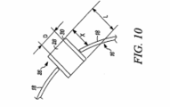
[037] A figura 10 é uma vista recortada lateral parcial de uma modalidade de um ressalto da presente invenção.[037] Figure 10 is a partial side cut-away view of an embodiment of a shoulder of the present invention.
[038] Nas figuras 5-7 e 10 uma primeira modalidade de um bocal da presente invenção é indicada genericamente pelo numeral de referência 10. O bocal 10 é para descarregar pelo menos um fluido em um padrão de pulverização em uma corrente de fluido em um recipiente (não mostrado) e altera os padrões de fluido da corrente de fluido nas proximidades do bocal para inibir erosão do bocal e manter o padrão de pulverização. Em uma modalidade da presente invenção, o bocal descarrega uma mistura atomizada de um primeiro e segundo fluido. Em um exemplo da mesma, o primeiro fluido é óleo, o segundo fluido é gás ou vapor, e o recipiente é um recipiente de craqueamento catalítico. Entretanto, como pode ser reconhecido por aqueles com conhecimentos comuns na técnica pertinente baseada nos ensinamentos da presente invenção, os bocais da presente invenção são igualmente utilizáveis com qualquer um de inúmeros tipos diferentes de fluidos com relação a qualquer um de inúmeros tipos diferentes de aplicações que são atualmente conhecidas, ou que se tornam conhecidas posteriormente.[038] In figures 5-7 and 10 a first embodiment of a nozzle of the present invention is indicated generically by the reference numeral 10. The nozzle 10 is for discharging at least one fluid in a spray pattern into a fluid stream in one container (not shown) and changes the fluid patterns of the fluid stream in the vicinity of the nozzle to inhibit nozzle erosion and maintain the spray pattern. In one embodiment of the present invention, the nozzle discharges an atomized mixture of a first and second fluid. In one example, the first fluid is oil, the second fluid is gas or steam, and the container is a catalytic cracking container. However, as can be recognized by those of ordinary skill in the relevant technique based on the teachings of the present invention, the nozzles of the present invention are equally usable with any of a number of different types of fluids with respect to any of a number of different types of applications that they are currently known, or will become known later.
[039] O bocal 10 compreende uma porção de entrada 12 que define pelo menos um conduto de entrada 14 para receber pelo menos um fluido e, em uma modalidade, primeiro e segundo fluidos. Uma porção de saída 16 do bocal define uma superfície exterior 18 e uma pluralidade de aberturas 22 que se estendem através da superfície exterior 18 em comunicação de fluido com a porção de entrada 12 e angularmente espaçadas em relação mútua em torno de um eixo geométrico central 24 da porção de saída 16. Além disso, a porção de saída inclui uma pluralidade de ressaltos 26 ou protuberâncias angularmente espaçadas em relação mútua em torno de um eixo geométrico da saída. Cada ressalto define uma abertura de saída 28 através do mesmo que está em comunicação de fluido com pelo menos um con-duto de entrada e uma parede axialmente estendida 30. Em uma modalidade, a parede axialmente estendida 30 estende para fora por um comprimento (X) maior do que aproximadamente 0,32 cm (1/8polegada) em relação à superfície exterior 18 e tem uma espessura de parede de aproximadamente 5 mm ou 0,48 cm (3/16polegada). Tipicamente, os ressaltos 26 são aproximadamente de formato cilíndrico e as aberturas de saída são aproximadamente circulares. Deve ser observado, entretanto, que inúmeras configurações de ressalto 26 e abertura de saída 28 que são atualmente conhecidas ou que se tornam posteriormente conhecidas podem ser empregadas sem se afastar do espírito e escopo da invenção; por exemplo, um ressalto aproximadamente cilíndrico definindo uma abertura de saída retangular pode ser empregado como mostrado nas figuras 9A-B. Para assegurar que a direção da pulverização é ao longo do eixo geométrico da abertura 22, o plano de saída da pulverização a partir de cada ressalto individual 26 é aproximadamente perpendicular ao eixo geométrico da abertura 22 associado ao ressalto.[039] The nozzle 10 comprises an
[040] Como mostrado nas figuras 6A-B, 7 e 10, cada abertura de saída 28 de cada ressalto 26 tem um comprimento (L) e um diâmetro (D). Para manter um padrão de pulverização consistente e precisa à medida que o bocal desgasta em aplicações FCC ou similar, a razão L/D é mantida pelo menos em aproximadamente 1/2, o que é tornado possível pela adição do material do ressalto 26 em comparação com bocais tradicionais sem ressaltos. Nas representações das figuras 7 e 10, uma porção de comprimento (L) está localizada no interior da saída 16. O material adicional adicionado pelos ressaltos 26 permite que mais erosão ocorra antes do comprimento da abertura de saída L se tornar demasiadamente curta, o que reduz por sua vez a razão L/D a menos do que aproximadamente 1/2 fazendo com que a pulverização de ventoinha planta desejada se torne definida de forma ruim; à medida que a erosão continua adicionalmente, um padrão de pulverização de cone estreito, indesejável surge, que causa impacto negativo na eficiência dos processos de FCC ou RCC ou similar.[040] As shown in figures 6A-B, 7 and 10, each outlet opening 28 of each
[041] A porção de saída 16 e ressaltos 26 podem ser integrados como uma única peça, como mostrado nas figuras 6A-B ou, em uma modalidade alternativa (figura 7), os ressaltos 26 podem ser artigos separados adaptados nas aberturas 22 da porção de saída 16 e soldados e/ou mecanicamente fixados no lugar ou retidos no lugar por qualquer outro método de fixação apropriado que é atualmente conhecido ou que se torne posteriormente conhecido, desde que os ressaltos sejam man-tidos firmemente no lugar. A modalidade mencionada por último oferece o benefício de que ressaltos individuais 26 podem ser alterados sem ter de substituir a porção de saída inteira 16 do bocal e os ressaltos 26 podem ser feitos de um material que difere da saída de bocal 16.[041] The
[042] As aberturas de saída 22 são, preferivelmente, configuradas para formar um padrão de pulverização de ventoinha substancialmente plana, de acordo com os ensinamentos das patentes US números 5.553.783 e 5.692.682, ambas intituladas “Flat Fan spray nozzle”, e cada uma das quais é cedida à cessionária da presente invenção e é pelo presente expressamente incorporada a título de referência na íntegra como parte da presente revelação. De acordo com os ensinamentos das patentes acima, aproximadamente todos os eixos geométricos de fluxo das aberturas de saída 22 são orientados para um alvo “T” (não mostrado) dentro do recipiente para atomizar e orientar uma mistura dos primeiro e segundo fluidos em um padrão de pulverização que flui em uma direção através do alvo, e o alvo é substancialmente localizado em um plano que se estende na direção de fluxo do padrão de pulverização. Além disso, o eixo geométrico de fluxo de cada abertura de saída 22 é orientada para intersectar o alvo “T” de tal modo que as aberturas de saída 22 cooperam para definir um padrão de pulverização de ventoinha substancialmente plano, e o alvo “T” é substancialmente localizado em um plano orientado em um ângulo agudo em relação a um eixo geométrico vertical do recipiente. Em uma modalidade da presente invenção, o alvo “T” é linear e aproximadamente intersecta o eixo geométrico central da superfície extrema 18 da porção de saída.[042] The outlet openings 22 are preferably configured to form a substantially flat fan spray pattern, in accordance with the teachings of US patent numbers 5,553,783 and 5,692,682, both entitled “Flat Fan spray nozzle”, and each of which is assigned to the assignee of the present invention and is hereby expressly incorporated by reference in its entirety as part of the present disclosure. According to the teachings of the above patents, approximately all of the flow's geometric axes from the outlet openings 22 are oriented towards a “T” target (not shown) within the container to atomize and orient a mixture of the first and second fluids in a pattern spray that flows in one direction through the target, and the target is substantially located on a plane that extends in the direction of flow of the spray pattern. In addition, the geometric flow axis of each outlet opening 22 is oriented to intersect target “T” in such a way that outlet openings 22 cooperate to define a substantially flat fan spray pattern, and target “T” it is substantially located on a plane oriented at an acute angle to a vertical geometric axis of the container. In one embodiment of the present invention, the target "T" is linear and approximately intersects the central geometric axis of the
[043] O bocal 10 compreende ainda uma câmara de mistura (não mostrada) em comunicação de fluido entre a porção de entrada 12 e a porção de saída 16 para misturar pelo menos um fluido no mesmo. Em uma modalidade, a câmara de mistura é formada na porção de saída 16 imediatamente à montante das aberturas de saída 22.[043] The nozzle 10 further comprises a mixing chamber (not shown) in fluid communication between the
[044] Em uma modalidade, o bocal 10 compreende ainda preferivelmente pelo menos uma palheta (não mostrada) localizada entre a câmara de mistura e a porção de entrada 12, e estendendo transversalmente em relação a um eixo geométrico alongado da porção de entrada para receber uma porção dos primeiro e segundo fluidos e criando um fluxo anular em espiral, e definindo pelo menos uma porção de uma abertura em uma porção aproximadamente central da mesma para receber uma porção dos primeiro e segundo fluidos e criando um fluxo substancialmente axial. As palhetas atualmente consideradas e o modo de incorporar cada palheta nos bocais da presente invenção são mostrados nas patentes comumente cedidas incorporadas a título de referência acima. Em uma tal modalidade, cada palheta define um lóbulo substancialmente convexo e um lóbulo substancialmente côncavo. Nessa modalidade, cada lóbulo é aproximadamente semicircular, e o lóbulo convexo é localizado a montante em relação ao lóbulo côncavo. Preferivelmente, o bocal compreende duas palhetas, onde cada palheta estende transversalmente através de uma porção substancial mente semicircular respectiva da porção de entrada 12. Como alternativa à(s) palheta(s), o bocal pode compreender um elemento de pulverização (não mostrado) que estende de forma helicoidal na direção a partir da porção de entrada em direção à porção de saída, como descrito adicionalmente nas patentes comumente cedidas incorporadas a título de referência acima.[044] In one embodiment, the nozzle 10 preferably further comprises at least one reed (not shown) located between the mixing chamber and the
[045] O bocal 10 é particularmente apropriado para uso como um distribuidor de alimentação em unidades de craqueamento catalítico fluidizado (“FCCU”) e unidades de conversão bruta reduzida (“RCCU”). FCCU e RCCU convertem, tipicamente, materiais que consistem essencialmente de hidrocarbonetos do tipo de petróleo que são líquidos em temperatura normal ou mais elevada e pressão normal, ou material reciclado, principalmente para produzir combustíveis líquidos de motor ou outros ou naftas de um peso molecular médio mais baixo do que aquele do estoque de carga, juntamente com hidrocarbonetos normalmente gasosos de subproduto. A conversão é tipicamente realizada:
- a) em temperaturas em excesso de aproximadamente 260 graus Celsius; e
- b) com um catalisador sólido presente na zona de reação para a finalidade específica de efetuar ou influenciar a reação e pelo que é produzido um resultado com relação a rendimento, tipo de produto ou velocidade de reação diferente a um grau definitivamente determinável a partir do resultado que seria produzido com os mesmos materiais de partida sob condições de outro modo iguais porém, na ausência desse catalisador.
- a) at temperatures in excess of approximately 260 degrees Celsius; and
- b) with a solid catalyst present in the reaction zone for the specific purpose of effecting or influencing the reaction and for which a result is produced with respect to yield, type of product or different reaction speed to a degree definitely determinable from the result that would be produced from the same starting materials under otherwise equal conditions, however, in the absence of that catalyst.
[046] Também tipicamente em tais unidades (1) a conversão e regeneração de catalisador prosseguem em zonas separadas com transferência de catalisador entre zonas, (2) o catalisador é mantido na zona de reação na forma de uma massa de fluido composta de catalisador sólido finamente dividido disperso nos vapores de hidrocarboneto sendo submetidos à conversão, e (3) o tempo de permanência médio do catalisador na zona de reação é maior do que o tempo de permanência médio dos vapores de hidrocarboneto na zona de reação.[046] Also typically in such units (1) the conversion and regeneration of catalyst proceeds in separate zones with transfer of catalyst between zones, (2) the catalyst is kept in the reaction zone in the form of a fluid mass composed of solid catalyst finely divided dispersed in the hydrocarbon vapors being subjected to conversion, and (3) the average residence time of the catalyst in the reaction zone is greater than the average residence time of the hydrocarbon vapors in the reaction zone.
[047] Nas figuras 8A-8B, outra modalidade de um bocal da presente invenção é indicada genericamente pelo número de referência 110. O bocal 110 é similar em certos aspectos ao bocal 10 descrito acima com referência às figuras 5-7 e 10, e portanto números de referência similares precedidos pelo numeral “1” são utilizados para indicar elementos similares. Como o bocal 10, o bocal 110 é fornecido para descarregar primeiro e segundo fluidos em uma pulverização atomizada para dentro de um recipiente (não mostrado). O bocal 110 inclui uma entrada 112 e uma saída 116. A saída 112 define ainda uma superfície exterior 118 e dois elementos semelhantes à parede elevados 136, 138 que criam um ressalto contínuo 126 que circunda o eixo geométrico central 124 da saída 116. O ressalto contínuo 126 define uma pluralidade de aberturas de saída 122 através das quais pelo menos um fluido é descarregado em um padrão de pulverização plana como o padrão de pulverização de ventoinha plana descrito acima. As porções semelhantes à parede elevada permitem que o ressalto estenda pelo menos aproximadamente 0,32 cm (1/8polegada) em relação à superfície externa 118 da saída 116. Cada abertura de saída tem um comprimento (L) e diâmetro (D) de tal modo que a razão L/D é mantida pelo menos em aproximadamente 1/2 para manter a integridade do padrão de pulverização por um período alongado à medida que o bocal 112 desgasta, em relação às configurações de bocal da técnica anterior devido ao material de ressalto adicionado. Essa modalidade é particularmente útil em aplicações que exigem aberturas de diâmetro maior onde ressaltos individuais poderiam interferir um no outro.[047] In figures 8A-8B, another embodiment of a nozzle of the present invention is indicated generically by
[048] Uma vantagem dos bocais 10, 110 é que a inclusão de ressaltos angularmente espaçados 26 modifica padrões de fluxo de catalisador no recipiente FCC nas proximidades do bocal e torna o bocal menos propenso a (inibe) os efeitos negativos de erosão que ocorrem em processos FCC ou similar, desse modo aumentando a vida útil dos bocais em comparação com bocais de pulverização da técnica anterior. Outra vantagem dos bocais 10, 110 é que a configuração de ressalto mantém uma razão L/D mínima de pelo menos aproximadamente 1/2, que por sua vez, permite que o bocal 10 descarregue pelo menos um fluido em um padrão de pulverização consistentemente plano no catalisador ou corrente de fluido no recipiente para um ciclo prolongado de vida à medida que a erosão ocorre. Ainda outra vantagem do bocal 10 é que por manter um padrão de pulverização plana, o processo FCC se torna mais eficiente, à medida que o fluido descarregado do bocal interage com o catalisador em um modo mais consistente. Ainda outra vantagem dos bocais 10, 110 é que os ressaltos podem ser utilizados para controlar a espessura de ventoinha plana ou modificar seu formato. Com a razão L/D de pelo menos aproximadamente 1/2 fornecida pela adição dos ressaltos 26, 126, o jato de pulverização assim produzido é mais estreito e melhor definido. Essa propriedade pode, por exemplo, ser utilizada para tornar a ventoinha plana mais delgada, que é uma vantagem em um processo FCC ou RCC porque assegura que o contato de catalisador/óleo seja quase instantâneo.[048] An advantage of
[049] Como pode ser reconhecido por aqueles versados na técnica pertinente com base nos ensinamentos da presente invenção, inúmeras alterações e modificações podem ser feitas nas modalidades descritas acima e outras dos bocais da presente invenção sem se afastar do espírito e escopo da invenção como definido nas reivindicações apensas. Por exemplo, os ressaltos de bocal e aberturas de saída podem e assumem inúmeros formatos e configurações que são atualmente conhecidos ou que se tornem posteriormente conhecidos. Além disso, a orientação dos ressaltos e aberturas de saída com relação ao eixo geométrico central da saída pode ser alterada. Ainda adicionalmente, qualquer um de inúmeros materiais diferentes, configurações de abertura de saída, configurações de padrão de pulverização, câmaras de mistura, estruturas de mistura e/ou atomizadores, que são atualmente conhecidos, ou que se tornem posteriormente conhecidos, podem ser empregados nos vários bocais da presente invenção. Por conseguinte, essa descrição detalhada de modalidades atualmente preferidas deve ser tomada em um sentido ilustrativo, ao contrário de limitador.[049] As can be recognized by those skilled in the relevant technique based on the teachings of the present invention, numerous changes and modifications can be made in the modalities described above and other of the nozzles of the present invention without departing from the spirit and scope of the invention as defined in the attached claims. For example, nozzle bosses and outlet openings can and assume numerous shapes and configurations that are currently known or that will become known later. In addition, the orientation of the exit bosses and openings with respect to the central geometric axis of the exit can be changed. In addition, any of a number of different materials, outlet opening configurations, spray pattern configurations, mixing chambers, mixing structures and / or atomisers, which are currently known, or which will later become known, can be employed in various nozzles of the present invention. Therefore, this detailed description of currently preferred modalities should be taken in an illustrative, as opposed to limiting, sense.
Claims (22)
uma entrada (12, 112) que define pelo menos um conduto de entrada (14); e
uma saída (16, 116) em comunicação de fluido com a entrada (12, 112), a saída (16,116) definindo uma superfície exterior (18,118);
CARACTERIZADO pelo fato de que
a saída (16, 116) define uma pluralidade de ressaltos (26, 126) angularmente espaçados em relação mútua em torno de um eixo geométrico da saída (16, 116), cada ressalto (26, 126) definindo uma abertura de saída (28) em comunicação de fluido com pelo menos um conduto de entrada (14) tendo um comprimento (L) e um diâmetro (D) e uma parede axialmente estendida (30), em que a parede axialmente estendida (30) se estende para fora por um comprimento (X) maior do que 0,32 cm (1/8 polegada) em relação à superfície exterior (18, 118) e L/D é pelo menos 1/2; e
o bocal (10, 110) altera os padrões de fluxo da corrente de fluido nas proximidades do bocal (10,110) para inibir a erosão do bocal (10, 110) e manter o padrão de pulverização.Spray nozzle (10, 110) to discharge at least one fluid in a spray pattern into a stream of fluid in a container, the nozzle (10, 110) comprising:
an inlet (12, 112) defining at least one inlet conduit (14); and
an outlet (16, 116) in fluid communication with the inlet (12, 112), the outlet (16,116) defining an outer surface (18,118);
CHARACTERIZED by the fact that
the outlet (16, 116) defines a plurality of angles (26, 126) angularly spaced in mutual relation around a geometric axis of the outlet (16, 116), each shoulder (26, 126) defining an outlet opening (28 ) in fluid communication with at least one inlet conduit (14) having a length (L) and diameter (D) and an axially extended wall (30), wherein the axially extended wall (30) extends outwardly a length (X) greater than 0.32 cm (1/8 inch) in relation to the outer surface (18, 118) and L / D is at least 1/2; and
the nozzle (10, 110) changes the flow patterns of the fluid stream in the vicinity of the nozzle (10,110) to inhibit erosion of the nozzle (10, 110) and maintain the spray pattern.
uma entrada (12, 112) definindo pelo menos um conduto de entrada (14); e
uma saída (16, 116) em comunicação de fluido com a entrada (12, 112), a saída (16, 116) definindo uma superfície exterior (18, 118);
CARACTERIZADO pelo fato de que
dois elementos de parede (30) formam um único ressalto contínuo (26, 126) em torno de um eixo geométrico central da saída (16, 116), o ressalto contínuo (26, 126) definindo uma pluralidade de aberturas de saída (28) tendo um comprimento (L) e um diâmetro (D) angularmente espaçadas em relação mútua em torno do eixo geométrico central da saída (16, 116) e em comunicação de fluido com pelo menos um conduto de entrada (14), em que os elementos de parede (30) se estendem para fora por um comprimento (X) maior do que 0,32 cm (1/8 polegada) em relação à superfície exterior (18, 118) e L/D é pelo menos 1/2; e
o bocal (10, 110) altera os padrões de fluxo da corrente de fluido nas proximidades do bocal (10,110) para inibir a erosão do bocal (10, 110) e manter o padrão de pulverização.Spray nozzle (10, 110) to discharge at least one fluid in a spray pattern into a stream of fluid in a container, the nozzle (10, 110) comprising:
an inlet (12, 112) defining at least one inlet conduit (14); and
an outlet (16, 116) in fluid communication with the inlet (12, 112), the outlet (16, 116) defining an outer surface (18, 118);
CHARACTERIZED by the fact that
two wall elements (30) form a single continuous boss (26, 126) around a central geometric axis of the outlet (16, 116), the continuous boss (26, 126) defining a plurality of outlet openings (28) having a length (L) and a diameter (D) angularly spaced in mutual relation around the central geometric axis of the outlet (16, 116) and in fluid communication with at least one inlet conduit (14), in which the elements wall (30) extending outward for a length (X) greater than 0.32 cm (1/8 inch) in relation to the outer surface (18, 118) and L / D is at least 1/2; and
the nozzle (10, 110) changes the flow patterns of the fluid stream in the vicinity of the nozzle (10,110) to inhibit erosion of the nozzle (10, 110) and maintain the spray pattern.
fornecer um bocal de pulverização (10, 110) para descarregar pelo menos um fluido em um padrão de pulverização no recipiente, em que o bocal de pulverização (10, 110) compreende um elemento de entrada (12, 112) que define pelo menos um conduto de entrada (14) para receber pelo menos um fluido, e um elemento de saída (16, 116) em comunicação de fluido com o elemento de entrada (12, 112), o elemento de saída (16,116) definindo uma superfície exterior (18, 118); e
introduzir uma corrente de fluido no recipiente;
CARACTERIZADO pelo fato de que
uma pluralidade de aberturas (22, 122) é angularmente espaçada em relação mútua em torno de um eixo geométrico do elemento de saída (16,116); e
o método inclui fornecer uma pluralidade de elementos de ressalto (26, 126), cada elemento de ressalto (26, 126) sendo adaptado em uma respectiva abertura (22, 122) e definindo uma abertura de saída (28) em comunicação de fluido com pelo menos um conduto de entrada (14) tendo um comprimento (L) e um diâmetro (D) e uma parede axialmente estendida (30), em que a parede axialmente estendida (30) estende para fora por um comprimento (X) maior do que 0,32 cm (1/8 polegada) em relação à superfície exterior (18, 118) e L/D é pelo menos 1/2.Method of maintaining a spray pattern of at least one fluid sprayed through a nozzle (10, 110) into a fluid stream from a container and inhibiting nozzle erosion (10,110), comprising the steps of:
providing a spray nozzle (10, 110) to discharge at least one fluid in a spray pattern into the container, wherein the spray nozzle (10, 110) comprises an inlet element (12, 112) that defines at least one inlet conduit (14) for receiving at least one fluid, and an outlet element (16, 116) in fluid communication with the inlet element (12, 112), the outlet element (16,116) defining an outer surface ( 18, 118); and
introduce a stream of fluid into the container;
CHARACTERIZED by the fact that
a plurality of openings (22, 122) are angularly spaced with respect to each other around a geometric axis of the outlet element (16,116); and
the method includes providing a plurality of boss elements (26, 126), each boss element (26, 126) being adapted into a respective opening (22, 122) and defining an outlet opening (28) in fluid communication with at least one inlet conduit (14) having a length (L) and a diameter (D) and an axially extended wall (30), wherein the axially extended wall (30) extends outwardly for a length (X) greater than that 0.32 cm (1/8 inch) with respect to the outer surface (18, 118) and L / D is at least 1/2.
Applications Claiming Priority (3)
| Application Number | Priority Date | Filing Date | Title |
|---|---|---|---|
| US90115107P | 2007-02-13 | 2007-02-13 | |
| US60/901,151 | 2007-02-13 | ||
| PCT/US2008/053827 WO2008100998A1 (en) | 2007-02-13 | 2008-02-13 | Spray nozzles |
Publications (2)
| Publication Number | Publication Date |
|---|---|
| BRPI0807909A2 BRPI0807909A2 (en) | 2019-09-03 |
| BRPI0807909B1 true BRPI0807909B1 (en) | 2020-11-24 |
Family
ID=39685011
Family Applications (1)
| Application Number | Title | Priority Date | Filing Date |
|---|---|---|---|
| BRPI0807909-9A BRPI0807909B1 (en) | 2007-02-13 | 2008-02-13 | spray nozzles |
Country Status (11)
| Country | Link |
|---|---|
| US (1) | US8025792B2 (en) |
| EP (1) | EP2121196B1 (en) |
| JP (1) | JP5559546B2 (en) |
| KR (1) | KR101177972B1 (en) |
| CN (1) | CN101652186B (en) |
| BR (1) | BRPI0807909B1 (en) |
| CA (1) | CA2678219C (en) |
| HK (1) | HK1140719A1 (en) |
| IL (1) | IL200405A (en) |
| MX (1) | MX2009008685A (en) |
| WO (1) | WO2008100998A1 (en) |
Families Citing this family (18)
| Publication number | Priority date | Publication date | Assignee | Title |
|---|---|---|---|---|
| JP5032627B2 (en) * | 2010-04-19 | 2012-09-26 | サンコール株式会社 | Multi-nozzle for liquid application |
| KR101249132B1 (en) | 2011-08-01 | 2013-04-02 | 주식회사 포스코 | Apparatus for preventing absorption of nitrogen stainless steel |
| US9492829B2 (en) * | 2013-03-11 | 2016-11-15 | Control Components, Inc. | Multi-spindle spray nozzle assembly |
| CN104801438A (en) * | 2015-04-20 | 2015-07-29 | 谢博 | Cleaning liquid spray head of crushing material washing machine |
| CN104889697A (en) * | 2015-06-19 | 2015-09-09 | 江西洪都航空工业集团有限责任公司 | Liquid spraying direction guide structure |
| US10130972B2 (en) * | 2015-09-09 | 2018-11-20 | Illinois Tool Works Inc. | High speed intermittent barrier nozzle |
| CN106362670B (en) * | 2016-10-27 | 2021-07-09 | 中国科学院工程热物理研究所 | Jet stirring reactor system |
| US10864494B2 (en) | 2017-06-07 | 2020-12-15 | Chevron Phillips Chemical Company Lp | Rotary feeder with cleaning nozzles |
| CN107096405A (en) * | 2017-06-08 | 2017-08-29 | 江苏天宇石化冶金设备有限公司 | A kind of high efficient gas and liquid blender |
| EP3797001B1 (en) * | 2018-05-21 | 2022-04-27 | SHL Medical AG | Micro nozzle assembly |
| CA3101818C (en) | 2018-06-21 | 2023-03-14 | The Procter & Gamble Company | Unitary dispensing nozzle for co-injection of two or more liquids and method of using same |
| CN112154104B (en) | 2018-06-22 | 2022-07-29 | 宝洁公司 | Liquid filling system and method of using the same |
| US11419791B2 (en) * | 2018-07-05 | 2022-08-23 | Fresenius Medical Care Holdings, Inc. | Flexible container systems and nozzles, and related methods |
| CN114630708A (en) | 2019-11-04 | 2022-06-14 | 鲁姆斯科技有限责任公司 | Fluid catalytic cracking feed injector |
| JP7181178B2 (en) * | 2019-11-19 | 2022-11-30 | 日立造船株式会社 | Nozzle and hydrolyzer |
| US20220048051A1 (en) * | 2020-08-17 | 2022-02-17 | Medtronic, Inc. | Helical Nozzle |
| JP7218335B2 (en) * | 2020-09-11 | 2023-02-06 | 三菱重工業株式会社 | Metal powder production equipment and its gas injector |
| US20220370975A1 (en) * | 2021-05-18 | 2022-11-24 | Uop Llc | Apparatus for distributing feed with a cluster of orifices on a side of the distributor |
Family Cites Families (39)
| Publication number | Priority date | Publication date | Assignee | Title |
|---|---|---|---|---|
| US2006049A (en) | 1932-07-27 | 1935-06-25 | Minerals Separation North Us | Concentration of ores by flotation |
| US2700576A (en) | 1951-10-30 | 1955-01-25 | Salsas-Serra Francisco | Apparatus for atomizing liquids |
| JPS5548867B2 (en) * | 1972-12-18 | 1980-12-09 | ||
| US3974091A (en) | 1974-08-29 | 1976-08-10 | Shell Oil Company | Fluidized bed regeneration of carbon-contaminated catalysts using gas discharge nozzles of specific dimensions |
| US4032300A (en) | 1975-05-02 | 1977-06-28 | Shell Oil Company | Oxygen-containing gas distribution apparatus employed in fluidized bed regeneration of carbon-contaminated catalysts |
| US4097243A (en) * | 1976-11-04 | 1978-06-27 | Uop Inc. | Hydrocarbon-feed distributor of injecting hydrocarbon feed |
| GB1569476A (en) | 1977-04-01 | 1980-06-18 | British Petroleum Co | Sparger nozzles |
| JPS6026439B2 (en) * | 1978-06-26 | 1985-06-24 | ユ−オ−ピ−・インコ−ポレ−テツド | Hydrocarbon feed liquid distribution method and its equipment |
| US4369849A (en) | 1980-06-05 | 1983-01-25 | Reed Rock Bit Company | Large diameter oil well drilling bit |
| DE3039633C2 (en) | 1980-10-21 | 1983-08-18 | Christensen, Inc., 84115 Salt Lake City, Utah | Rotary drill bits, in particular for deep drilling |
| US4443551A (en) | 1982-01-11 | 1984-04-17 | Texaco Inc. | Method and new distributor for delivering high velocity gas from a gas distributor through a nozzle with decreased erosion in the nozzle |
| JPS58175330U (en) * | 1982-05-20 | 1983-11-24 | バブコツク日立株式会社 | Mixed fuel atomizer |
| US5017536A (en) | 1984-02-03 | 1991-05-21 | Phillips Petroleum Company | Catalyst regeneration including method of introducing oxygen into fluidized bed |
| US4994239A (en) | 1984-02-03 | 1991-02-19 | Phillips Petroleum Company | Catalyst regeneration |
| US4875996A (en) * | 1986-02-28 | 1989-10-24 | Chevron Research Company | Method for liquid feed dispersion in fluid catalytic cracking systems |
| US4843050A (en) | 1986-06-27 | 1989-06-27 | Phillips Petroleum Company | Catalyst regeneration |
| WO1991012894A1 (en) * | 1990-02-22 | 1991-09-05 | Masco Gmbh | Sprinkler head |
| US5033681A (en) | 1990-05-10 | 1991-07-23 | Ingersoll-Rand Company | Ion implantation for fluid nozzle |
| US5474235A (en) | 1994-04-13 | 1995-12-12 | Wheelabrator Technologies, Inc. | Spray nozzle insert and method for reducing wear in spray nozzles |
| US5553783A (en) | 1995-01-09 | 1996-09-10 | Bete Fog Nozzle, Inc. | Flat fan spray nozzle |
| US5704554A (en) | 1996-03-21 | 1998-01-06 | University Of Georgia Reseach Foundation, Inc. | Electrostatic spray nozzles for abrasive and conductive liquids in harsh environments |
| US5692682A (en) | 1995-09-08 | 1997-12-02 | Bete Fog Nozzle, Inc. | Flat fan spray nozzle |
| WO1998004322A1 (en) * | 1996-07-26 | 1998-02-05 | The Reliable Automatic Sprinkler Co., Inc. | Fire suppression mist nozzle arrangement |
| US6042717A (en) | 1997-12-05 | 2000-03-28 | Uop Llc | Horizontal FCC feed injection process |
| US6142248A (en) | 1998-04-02 | 2000-11-07 | Diamond Products International, Inc. | Reduced erosion nozzle system and method for the use of drill bits to reduce erosion |
| US6387247B1 (en) * | 1999-09-03 | 2002-05-14 | Shell Oil Company | Feed injection system for catalytic cracking process |
| US6763902B2 (en) | 2000-04-12 | 2004-07-20 | Smith International, Inc. | Rockbit with attachable device for improved cone cleaning |
| JP2002336370A (en) * | 2001-05-16 | 2002-11-26 | Yamato Protec Co | Fine water jetting nozzle header |
| US7198201B2 (en) | 2002-09-09 | 2007-04-03 | Bete Fog Nozzle, Inc. | Swirl nozzle and method of making same |
| JP4068041B2 (en) * | 2002-10-22 | 2008-03-26 | 日本碍子株式会社 | Low NOx burner |
| DE50312078D1 (en) * | 2003-01-24 | 2009-12-10 | Turbotect Ltd | METHOD AND INJECTION NOZZLE FOR IMPLEMENTING A GAS FLOW WITH LIQUID DROPLETS |
| US20040195395A1 (en) | 2003-04-07 | 2004-10-07 | Mclaughlin Michael S. | Method and apparatus for spray nozzle improvement through the use of surface and sub-surface coatings |
| DE10361349B4 (en) * | 2003-12-17 | 2005-12-08 | Lechler Gmbh | cone nozzle |
| US7108195B2 (en) | 2004-02-05 | 2006-09-19 | Shell Oil Company | Protective shroud for FCC feed nozzles and method for designing such shroud |
| US20050214474A1 (en) * | 2004-03-24 | 2005-09-29 | Taeyoung Han | Kinetic spray nozzle system design |
| US7185830B2 (en) * | 2004-06-18 | 2007-03-06 | Malcolm David B | Uniform droplet spray nozzle for liquids |
| US7407572B2 (en) | 2004-07-23 | 2008-08-05 | Exxonmobil Research And Engineering Company | Feed injector |
| US7670478B2 (en) | 2004-12-30 | 2010-03-02 | Exxonmobil Research And Engineering Company | FCC feed injection system |
| US7201332B2 (en) * | 2005-05-23 | 2007-04-10 | Kwan-Ten Enterprise Co., Ltd. | Adjustable spray nozzle |
-
2008
- 2008-02-13 BR BRPI0807909-9A patent/BRPI0807909B1/en active IP Right Grant
- 2008-02-13 JP JP2009549696A patent/JP5559546B2/en active Active
- 2008-02-13 WO PCT/US2008/053827 patent/WO2008100998A1/en active Application Filing
- 2008-02-13 CA CA2678219A patent/CA2678219C/en active Active
- 2008-02-13 CN CN2008800116481A patent/CN101652186B/en active Active
- 2008-02-13 MX MX2009008685A patent/MX2009008685A/en active IP Right Grant
- 2008-02-13 US US12/030,402 patent/US8025792B2/en active Active
- 2008-02-13 EP EP08729746.1A patent/EP2121196B1/en active Active
- 2008-02-13 KR KR1020097019181A patent/KR101177972B1/en active IP Right Grant
-
2009
- 2009-08-13 IL IL200405A patent/IL200405A/en active IP Right Grant
-
2010
- 2010-07-23 HK HK10107117.1A patent/HK1140719A1/en unknown
Also Published As
| Publication number | Publication date |
|---|---|
| EP2121196C0 (en) | 2023-06-21 |
| CA2678219A1 (en) | 2008-08-21 |
| EP2121196A4 (en) | 2016-11-16 |
| US20080191056A1 (en) | 2008-08-14 |
| HK1140719A1 (en) | 2010-10-22 |
| MX2009008685A (en) | 2010-01-20 |
| CN101652186A (en) | 2010-02-17 |
| BRPI0807909A2 (en) | 2019-09-03 |
| CN101652186B (en) | 2012-10-03 |
| JP5559546B2 (en) | 2014-07-23 |
| WO2008100998A1 (en) | 2008-08-21 |
| CA2678219C (en) | 2013-01-29 |
| IL200405A0 (en) | 2010-04-29 |
| US8025792B2 (en) | 2011-09-27 |
| KR20090122947A (en) | 2009-12-01 |
| EP2121196A1 (en) | 2009-11-25 |
| IL200405A (en) | 2013-02-28 |
| KR101177972B1 (en) | 2012-08-28 |
| JP2010517773A (en) | 2010-05-27 |
| EP2121196B1 (en) | 2023-06-21 |
Similar Documents
| Publication | Publication Date | Title |
|---|---|---|
| BRPI0807909B1 (en) | spray nozzles | |
| US5979799A (en) | Feed nozzle | |
| US9421557B2 (en) | Spray nozzles | |
| ATE240378T1 (en) | INSERT INJECTION SYSTEM FOR CATALYTIC CRACKING PROCESS | |
| ZA200603658B (en) | Feed Nozzle Assembly | |
| AU687675B2 (en) | Feed nozzle assembly | |
| ES2251152T3 (en) | SPRAY TOWER AND METHOD OF USE OF THE SAME. | |
| RU2757289C2 (en) | Improved pressure injection pipe for cracking plant with fluidized catalyst | |
| RU2678674C2 (en) | Injection device, in particular for injecting a hydrocarbon feedstock into a refining unit | |
| US6026591A (en) | Vertical shaft processor with improved gas delivery system | |
| CA2214751C (en) | Feed nozzle assembly | |
| KR20200116108A (en) | Raw material oil injection device of FCC unit with large cross section locally | |
| KR200230515Y1 (en) | T-type Nozzle Operates For The Fluidized Bed Reactor | |
| MXPA97006740A (en) | Assembly of food nozzle |
Legal Events
| Date | Code | Title | Description |
|---|---|---|---|
| B06U | Preliminary requirement: requests with searches performed by other patent offices: procedure suspended [chapter 6.21 patent gazette] | ||
| B06A | Patent application procedure suspended [chapter 6.1 patent gazette] | ||
| B09A | Decision: intention to grant [chapter 9.1 patent gazette] | ||
| B16A | Patent or certificate of addition of invention granted [chapter 16.1 patent gazette] |
Free format text: PRAZO DE VALIDADE: 10 (DEZ) ANOS CONTADOS A PARTIR DE 24/11/2020, OBSERVADAS AS CONDICOES LEGAIS. |