BRPI0703733B1 - ENGINE STARTING DEVICE - Google Patents
ENGINE STARTING DEVICE Download PDFInfo
- Publication number
- BRPI0703733B1 BRPI0703733B1 BRPI0703733-3A BRPI0703733A BRPI0703733B1 BR PI0703733 B1 BRPI0703733 B1 BR PI0703733B1 BR PI0703733 A BRPI0703733 A BR PI0703733A BR PI0703733 B1 BRPI0703733 B1 BR PI0703733B1
- Authority
- BR
- Brazil
- Prior art keywords
- construction group
- flat construction
- drive unit
- bypass switch
- switch
- Prior art date
Links
Images


Classifications
-
- H—ELECTRICITY
- H01—ELECTRIC ELEMENTS
- H01H—ELECTRIC SWITCHES; RELAYS; SELECTORS; EMERGENCY PROTECTIVE DEVICES
- H01H9/00—Details of switching devices, not covered by groups H01H1/00 - H01H7/00
- H01H9/54—Circuit arrangements not adapted to a particular application of the switching device and for which no provision exists elsewhere
- H01H9/541—Contacts shunted by semiconductor devices
- H01H9/542—Contacts shunted by static switch means
-
- H—ELECTRICITY
- H01—ELECTRIC ELEMENTS
- H01H—ELECTRIC SWITCHES; RELAYS; SELECTORS; EMERGENCY PROTECTIVE DEVICES
- H01H50/00—Details of electromagnetic relays
- H01H50/02—Bases; Casings; Covers
- H01H50/021—Bases; Casings; Covers structurally combining a relay and an electronic component, e.g. varistor, RC circuit
-
- H—ELECTRICITY
- H01—ELECTRIC ELEMENTS
- H01H—ELECTRIC SWITCHES; RELAYS; SELECTORS; EMERGENCY PROTECTIVE DEVICES
- H01H50/00—Details of electromagnetic relays
- H01H50/44—Magnetic coils or windings
- H01H50/443—Connections to coils
Landscapes
- Physics & Mathematics (AREA)
- Electromagnetism (AREA)
- Motor And Converter Starters (AREA)
- Electrical Control Of Air Or Fuel Supplied To Internal-Combustion Engine (AREA)
Abstract
DISPOSITIVO DE PARTIDA DO MOTOR. A presente invenção refere-se a um dispositivo de partida do motor (1) aperfeiçoado quanto à técnica de fabricação, O dispositivo de partida do motor (1) abrange uma chave semicondutora de potência (2), uma chave de by-pass (3) eletromecânica ligada a ela em paralelo, bem como, um mecanismo eletrônico de controle (5) para o controle da chave de bypass (3), sendo que, o mecanismo eletrônico de controle (5) é realizado na forma de um grupo de construção plano (4) fixado na chave de by-pass (3) em um estado de montagem e, sendo que, o grupo de construção plano (4) e a chave de by-pass (3) são executados, de tal modo que, durante a fixação, o grupo de construção plano (4) é simultaneamente contatado eletricamente com a chave de by-pass (3).ENGINE STARTING DEVICE. The present invention relates to an engine starting device (1) improved in terms of manufacturing technique. The engine starting device (1) comprises a power semiconductor switch (2), a bypass switch (3 ) electromechanical connected to it in parallel, as well as an electronic control mechanism (5) for controlling the bypass switch (3), whereby the electronic control mechanism (5) is realized in the form of a construction group plane (4) fixed on the bypass switch (3) in an assembly state and, being that, the construction group plane (4) and the bypass switch (3) are executed, in such a way that, during clamping, the flat construction group (4) is simultaneously electrically contacted with the bypass switch (3).
Description
[001] A presente invenção refere-se a um dispositivo de partida do motor com uma chave semicondutora de potência, com uma chave de by-pass eletromecânica ligada a ela em paralelo, bem como, com um mecanismo eletrônico de controle, para o controle da chave de bypass.[001] The present invention relates to a motor starting device with a semiconductor power switch, with an electromechanical bypass switch connected to it in parallel, as well as with an electronic control mechanism for controlling of the bypass switch.
[002] Dispositivos de partida do motor deste tipo também são designados como "dispositivos de partida suaves". No caso de um dispositivo de partida do motor deste tipo, durante uma fase de partida, o motor é ligado através da chave semicondutora de potência que, por exemplo, é executada como tiristor, enquanto a chave de by-pass paralela é aberta. Neste caso, através de controle correspondente da chave semicondutora de potência, a potência de partida do motor é aumentada, em particular, regulada de modo contínuo e aos poucos, de tal forma que, o motor inicia a operação de partida não por sacudidas, mas de modo "suave". Porém, de forma desvantajosa, na operação do motor, as chaves semicondutoras de potência tradicionalmente usadas iriam jogar fora uma potência de dissipação relativamente alta. A fim de evitar esta potência de dissipação, após o término da fase de partida a corrente de alimentação para o motor não é mais conduzida através da chave semicondutora de potência, mas através da chave de bypass, que como membro de ligação mecânico tem consideravelmente menos dissipações. Em geral é empregado um relé de ligação eletro- mecânico comum, como chave de by-pass que, em geral, abrange uma unidade de acionamento magnética para o acionamento do membro de ligação mecânico propriamente dito. A chave de by-pass é controlada através de um mecanismo eletrônico de controle, que é recebido em um denominado grupo de construção plana. Em geral, o grupo de construção plana é montado sobre ou ao lado da chave de by-pass, e é contatado com a chave de by-pass por meio de condutores de fio, em essência, livres. Os condutores são, por exemplo, soldados com cor-respondentes terminais do grupo de construção plana e contatados na chave de by-pass por meio de uma ligação de encaixe.[002] Motor starters of this type are also referred to as "soft starters". In the case of a motor starter of this type, during a starting phase, the motor is switched on via the power semiconductor switch, which, for example, operates as a thyristor, while the parallel bypass switch is open. In this case, through corresponding control of the power semiconductor switch, the starting power of the motor is increased, in particular, regulated continuously and little by little, in such a way that the motor starts the starting operation not by jolts, but in a "soft" way. However, disadvantageously, in motor operation, traditionally used power semiconductor switches would throw away relatively high power dissipation. In order to avoid this power dissipation, after the start-up phase has ended, the supply current to the motor is no longer conducted via the power semiconductor switch, but via the bypass switch, which as a mechanical link member has considerably less dissipations. In general, an ordinary electromechanical switching relay is used as a bypass switch, which generally comprises a magnetic drive unit for actuating the mechanical switching member itself. The bypass switch is controlled via an electronic control mechanism, which is received in a so-called flat-building group. In general, the flat construction group is mounted on or to the side of the bypass switch, and is contacted with the bypass switch via essentially free wire conductors. The conductors are, for example, soldered with corresponding terminals from the flat construction group and contacted at the bypass switch via a plug connection.
[003] Por um lado, esta solução tradicional é relativamente dispendiosa quanto ao espaço, em particular, visto que precisa ser previsto suficiente espaço livre para os condutores na carcaça do dispositivo de partida do motor. O contato entre o grupo de construção plana e a chave de by-pass exige, além disso, um dispêndio de montagem e de material relativamente alto. Dos condutores, em essência, soltos no estado de montagem e, com isto, suspensos no aparelho de modo in- controlável em certa extensão, parte, além disso, um certo risco de interferências da compatibilidade eletromagnética (EMV), bem como, um certo risco de interferências de funcionamento através de condutores defeituosos que sofreram batidas com danos ou de um contato de encaixe defeituoso.[003] On the one hand, this traditional solution is relatively expensive in terms of space, in particular, as sufficient free space needs to be provided for the conductors in the housing of the motor starter. The contact between the flat construction group and the bypass switch also requires relatively high assembly and material costs. The conductors, in essence, loose in the assembly state and, as a result, uncontrollably suspended in the apparatus to a certain extent, there is also a certain risk of interference from electromagnetic compatibility (EMV) as well as a certain risk of malfunctions due to faulty conductors that have been knocked over with damage or a faulty plug contact.
[004] À invenção cabe a tarefa de aperfeiçoar um dispositivo de partida do motor do tipo mencionado no início diante do fundamento mencionado anteriormente.[004] The invention has the task of improving an engine starting device of the type mentioned at the beginning in view of the previously mentioned foundation.
[005] De acordo com a invenção está previsto executar o grupo de construção plana e a chave de by-pass, de tal modo que, em um estado de montagem eles sejam fixados um no outro, sendo que, durante a fixação, o grupo de construção plana é simultaneamente contatado eletricamente com a chave de by-pass.[005] According to the invention, it is planned to implement the group of flat construction and the by-pass switch, in such a way that, in an assembly state, they are fixed to each other, and, during the fixation, the group of flat construction is simultaneously electrically contacted with the by-pass switch.
[006] De preferência, a fixação entre o grupo de construção plana e a chave de by-pass é executada, de tal modo que, no estado de montagem, o grupo de construção plana e a chave de by-pass formam um componente interligado, em essência, rígido, que não pode ser separado novamente ou só pode ser separado mediante o emprego de força. Neste caso, de preferência, o grupo de construção plana está preso com a chave de by-pass com ligação de encaixe, sendo que, também podem ser empregados outros tipos de fixação como, por exemplo, aparafusamento, colagem, soldagem, etc.[006] Preferably, the fastening between the flat construction group and the bypass switch is performed in such a way that, in the assembled state, the flat construction group and the bypass switch form an interconnected component , in essence rigid, that cannot be separated again or can only be separated by the use of force. In this case, preferably, the flat construction group is fastened with the by-pass key with a plug-in connection, although other types of fastening can also be used, such as screwing, gluing, welding, etc.
[007] Contudo, no contexto da invenção, o termo fixação também pode ser entendido como simples fixação de posição do grupo de construção plana e da chave de by-pass um no outro, que de acordo com a determinação da montagem do dispositivo de partida do motor, é formada ou retida por meio de outros componentes do dispositivo de partida do motor, em particular, uma carcaça do mesmo.[007] However, in the context of the invention, the term fixing can also be understood as a simple position fixing of the flat construction group and the bypass switch on each other, which according to the determination of the starting device assembly of the motor, is formed or retained by means of other components of the motor starter, in particular, a housing of the same.
[008] No caso das duas variantes, é essencial no contexto da invenção, o fato de que, no estado de montagem, o grupo de construção plana e a chave de by-pass estão dispostos entre si em uma posição bem definida e que, em conseqüência deste posicionamento, o grupo de construção plana seja simultaneamente contatado eletricamente com a chave de by-pass. Com isto não se aplicam os condutores normalmente necessários para o contato entre o grupo de construção plana e a chave de by-pass, bem como, eventuais contatos por encaixe ou por solda, e todas as desvantagens normalmente ligadas com isto.[008] In the case of the two variants, it is essential in the context of the invention, the fact that, in the assembly state, the flat construction group and the bypass switch are arranged with each other in a well-defined position and that, as a result of this positioning, the flat construction group is simultaneously electrically contacted with the bypass switch. With this, the conductors normally required for contact between the flat construction group and the bypass switch do not apply, as well as any contacts by fitting or soldering, and all the disadvantages normally connected with this.
[009] Em uma execução preferida, a chave de by-pass é formada por um membro de ligação mecânico, bem como, por uma unidade de acionamento, em particular, magnética, para o acionamento do mesmo. Em uma variante da invenção que particularmente economiza espaço, o grupo de construção plana é construído, de modo apropriado, como forma oca em forma de U ou em forma de cuba que, no estado de montagem, é emborcado sobre a unidade de acionamento, de tal modo que, a unidade de acionamento é recebida no interior da forma oca. Ao lado da economia de espaço, esta execução tem, em particular, as outras vantagens que, podem ser realizados trajetos elétricos particularmente curtos dentro do circuito de ligação formado pelo grupo de construção plana e pela unidade de acionamento, o que, por um lado, facilita o contato sem condutor entre o grupo de construção plana e a chave de by-pass, contudo, por outro lado, é vantajoso sob o aspecto da EMV . Além disso, através da parede externa do grupo de construção plana, a unidade de acionamento e a superfície interna do grupo de construção plana são, deste modo, eficazmente blindadas contra danos mecânicos, em particular, em virtude do processo de acabamento. Mediante o aproveitamento deste efeito de blindagem, são montados, em particular, componentes eletrônicos sensíveis mecanicamente do grupo de construção plana, de preferência, na superfície interna do mesmo.[009] In a preferred embodiment, the bypass switch is formed by a mechanical connection member, as well as by a drive unit, in particular magnetic, for driving it. In a particularly space-saving variant of the invention, the flat construction group is suitably constructed as a U-shaped or bowl-shaped hollow which, in the assembled state, is overturned onto the drive unit, so such that the drive unit is received within the hollow form. In addition to saving space, this design has the other advantages in particular that particularly short electrical paths can be realized within the connection circuit formed by the flat construction group and the drive unit, which, on the one hand, it facilitates the conductorless contact between the flat construction group and the bypass switch, however, on the other hand, it is advantageous from the EMV aspect. Furthermore, through the outer wall of the flat building group, the drive unit and the inner surface of the flat building group are thus effectively shielded against mechanical damage, in particular by virtue of the finishing process. By taking advantage of this shielding effect, mechanically sensitive electronic components in particular from the flat construction group are mounted, preferably on the inner surface thereof.
[0010] De modo apropriado, na posição de montagem, o grupo de construção plana está fixado na unidade de acionamento da chave de by-pass e é fixado ali, em particular, diretamente próximo dos pontos de contato. Deste modo é alcançado um contato elétrico particularmente estável e seguro contra falha. A fixação do grupo de construção plana na unidade de acionamento também é vantajosa, em particular, quando a unidade de acionamento da chave de by-pass pode ser separada do membro de ligação propriamente dito. Neste caso, em virtude da montagem, a unidade de acionamento e o grupo de construção plana podem ser primeiramente ligados e contatados separadamente, e somente em uma etapa de acabamento seguinte podem ser colocados como componente sobre o membro de ligação, o que sob o ponto de vista da técnica de produção é vantajoso.[0010] Suitably, in the mounting position, the flat construction group is fixed on the bypass switch drive unit and is fixed there, in particular, directly close to the contact points. In this way, a particularly stable and fail-safe electrical contact is achieved. Attaching the flat construction group to the drive unit is also advantageous, in particular when the bypass switch drive unit can be separated from the connecting member itself. In this case, due to the assembly, the drive unit and the flat construction group can first be connected and contacted separately, and only in a subsequent finishing step can they be placed as a component on the connecting member, which under the point from the point of view of production technique is advantageous.
[0011] Para um contato entre o grupo de construção plana e a chave de by-pass, em particular, a unidade de acionamento do mesmo, que seja simples de realizar sob o ponto de vista da técnica de produção, de custo vantajoso e seguro contra falha, de preferência, está previsto, pelo menos, um contato de mola.[0011] For a contact between the flat construction group and the by-pass switch, in particular, its drive unit, which is simple to carry out from the point of view of production technique, cost-effective and safe against failure, preferably at least one spring contact is provided.
[0012] A fim de simplificar tanto a equipagem do grupo de constru- ção plana com componentes eletrônicos, como também a colocação do grupo de construção plana na chave de by-pass, de modo apropriado o grupo de construção plana é executado flexível. Em uma forma de execução preferida, o grupo de construção plana está equipado com pontos de dobramento teórico, em particular, na forma de dobradiças de filme, em torno das quais o grupo de construção plana pode ser dobrado sem destruição. De forma alternativa ou adicional, o grupo de construção plana também pode ser composto opcionalmente de várias partes.[0012] In order to simplify both the equipping of the flat construction group with electronic components, as well as the placement of the flat construction group on the bypass switch, appropriately the flat construction group is executed flexibly. In a preferred embodiment, the flat construction group is equipped with theoretical folding points, in particular in the form of film hinges, around which the flat construction group can be folded without destruction. Alternatively or additionally, the flat construction group can optionally also be composed of several parts.
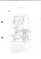
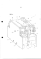
[0013] A seguir será esclarecido, em detalhes, um exemplo de execução da invenção com auxílio de um desenho. Nele são mostrados: na figura 1, uma vista esquemática em perspectiva de um dispositivo de partida do motor, com uma chave semicondutora de potência, uma chave de by-pass eletromecânica ligada em paralelo com ela, bem como, com um grupo de construção plana que contém um mecanismo eletrônico de controle para o controle da chave de by-pass, na figura 2, em representação em perspectiva girada em relação à figura 1, a chave de by-pass do dispositivo de partida do motor, com um membro de ligação mecânico, bem como, com uma unidade de acionamento eletromagnética, na figura 3, em representação em perspectiva girada de novo, a unidade de acionamento da chave de by-pass com uma placa do condutor do grupo de construção plana montada na unidade, na figura 4, em representação em perspectiva girada de novo, a unidade de acionamento e a placa do condutor do grupo de construção plana equipada, a partir de agora, com componentes eletrônicos, bem como, na figura 5, um recorte V ampliado da figura 1, de um contato de mola para o contato do grupo de construção plana com o elemen- to da chave de by-pass.[0013] Below, an example of execution of the invention with the aid of a drawing will be clarified in detail. In it are shown: in figure 1, a schematic view in perspective of a motor starting device, with a power semiconductor switch, an electromechanical bypass switch connected in parallel with it, as well as, with a flat construction group containing an electronic control mechanism for controlling the bypass switch, in figure 2, in perspective representation rotated with respect to figure 1, the bypass switch of the engine starter, with a connecting member mechanical as well as, with an electromagnetic drive unit, in figure 3, in perspective representation rotated again, the bypass switch drive unit with a conductor plate of the flat construction group mounted on the unit, in figure 4, in perspective view again rotated, the drive unit and the conductor plate of the flat construction group equipped, from now on, with electronic components, as well as, in figure 5, an enlarged V section of figure 1, in a spring contact for flat construction group contact with the bypass switch element.
[0014] Partes correspondentes entre si estão sempre dotadas em todas as figuras com os mesmos números de referência.[0014] Corresponding parts are always provided in all figures with the same reference numbers.
[0015] O dispositivo de partida do motor 1 representado na figura 1 abrange uma chave semicondutora de potência 2, em particular, um tiristor. O dispositivo de partida do motor 1 abrange, além disso, uma chave de by-pass 3 eletromecânica, ligada em paralelo à chave semi- condutora de potência 2, bem como, um grupo de construção plana 4, que possui um mecanismo eletrônico de controle 5 para o controle da chave de by-pass 4.[0015] The motor starting device 1 shown in figure 1 comprises a power semiconductor switch 2, in particular, a thyristor. The engine starting device 1 comprises, moreover, an electromechanical by-
[0016] No estado de montagem mostrado na figura 1, a chave se- micondutora de potência 2, a chave de by-pass 3 e o grupo de construção plana 4 são recebidos em uma carcaça 6 comum, que está somente indicada com linhas de contorno na figura 1. No estado de montagem, da carcaça 6 se projetam somente contatos de ligação 7 e 7’ para a ligação de um condutor de corrente de acionamento para um motor (não representado).[0016] In the assembly state shown in figure 1, the power semiconductor switch 2, the
[0017] Na forma de execução de acordo com a figura 1 o dispositivo de partida do motor 1 é executado para ser ligado em um condutor de corrente de acionamento (neste caso, por exemplo, bifásico) para um motor. O dispositivo de partida do motor 1 abrange, de modo correspondente, respectivamente, um par de contatos de ligação 7 e 7’ para cada um dos dois condutores de fase, que se projetam da carcaça 6 em lados opostos e, nos quais pode ser ligada uma parte do lado da rede ou uma parte do lado do motor do condutor de corrente de acionamento.[0017] In the execution form according to figure 1, the starting device of motor 1 is executed to be connected to a drive current conductor (in this case, for example, two-phase) for a motor. The motor starting device 1 correspondingly comprises, respectively, a pair of connection contacts 7 and 7' for each of the two phase conductors, which project from the frame 6 on opposite sides and, to which it can be connected a mains-side part or a motor-side part of the drive current conductor.
[0018] Aos contatos de ligação 7 e 7’ correspondentes são internamente intercaladas a chave semicondutora de potência 2 e a chave de by-pass 3 em ligação paralela.[0018] The power semiconductor switch 2 and the by-
[0019] De acordo com o uso determinado, o dispositivo de partida do motor 1 é ligado previamente ao motor acionado eletricamente no condutor de corrente de acionamento, e serve para ligar e desligar o motor. No caso do dispositivo de partida do motor 1 trata-se, neste caso, de um denominado dispositivo de partida suave, no qual a potência do motor é aumentada aos poucos, em particular, regulada, durante uma fase de partida do motor. Nesta fase de partida a chave de bypass 3 está aberta e, com isto, o motor está ligado com a rede através da chave semicondutora de potência 2. Neste caso, o aumento aos poucos, em particular, regulado, da potência do motor ocorre através de correspondente controle da chave semicondutora de potência 2. A fim de economizar a potência de dissipação, que cai durante a operação do motor na chave semicondutora de potência 2, após o término da fase de partida, a chave de by-pass 3 é fechada e, com isto, e é feita uma ponte sobre a chave semicondutora de potência 2, de tal modo que, a corrente de acionamento para o motor flui com pouca dissipação através da chave de by-pass 3.[0019] According to the determined use, the motor starting device 1 is previously connected to the electrically driven motor in the drive current conductor, and serves to turn the motor on and off. The motor starter 1 is a so-called soft starter, in which the motor power is gradually increased, in particular regulated, during a motor starting phase. In this starting phase, the
[0020] A chave de by-pass 3 do dispositivo de partida do motor 1 representada de novo separadamente na figura 2, compreende um membro de ligação 8 mecânico, que pode ser ligado por meio de uma unidade de acionamento eletromagnética 9.[0020] The by-
[0021] O membro de ligação 8 compreende um par de contatos fixos 10, 10’ que estão opostos um ao outro para cada condutor de fases, dos quais cada um está ligado eletricamente com um contato de ligação 7 ou 7’ correspondente. Os contatos fixos 10 e 10’ do mesmo condutor de fases podem ser ligados e separados respectivamente através de uma ponte de contato 11 eletricamente reversível.[0021] The connecting
[0022] Todas as pontes de contato 11 estão fixadas em um punção 12 comum, e são sempre acionadas em comum através do movimento do punção 12. Através de uma mola (não representada em detalhes) o punção 12 é tensionado previamente de tal modo que, as pontes de contato 11 no estado de repouso permanecem em uma posição de abertura representada na figura 2, na qual os contatos de ligação 7, 7’ de cada um dos condutores de fases são separados eletricamente um do outro.[0022] All contact bridges 11 are fixed to a
[0023] A unidade de acionamento 9 compreende uma bobina magnética 13 e uma culatra magnética 14, que formam um circuito magnético com um induzido magnético 15. O induzido magnético 15, neste caso, está fixado no punção 12, e com isso, forma - visto de modo construtivo - um componente do membro de ligação 8. Os componentes da unidade de acionamento 9, portanto, em particular, a bobina magnética 13 e a culatra magnética 14 estão reunidas em um grupo de construção interligado e, em essência, rígido, que está fixado no membro de ligação 8 por meio de uma ligação de encaixe 16.[0023] The
[0024] No estado de montagem, através da aplicação de uma tensão na bobina magnética 13, no circuito magnético é produzido um campo magnético. Sob o efeito desse campo magnético, o induzido magnético 15 é atraído para a culatra magnética 14 e, neste caso, através do punção 12 movimenta as pontes de contato 11 contra a pressão de mola da posição de abertura para a posição de fechamento, na qual os contatos fixos 10, 10’ correspondentes de cada condutor de fases são ligados entre si conduzindo eletricidade através das pontes de contato 11.[0024] In the assembled state, by applying a voltage to the
[0025] O grupo de construção plana 4 mostrado separadamente nas figuras 3 e 4, com a unidade de acionamento 9, é formado, em essência, de uma placa do condutor 17 com componentes 18 eletrônicos montados sobre essa placa, que são ligados ao mecanismo eletrônico de controle 5. Neste caso, em virtude da clareza, a figura 3 mostra a placa do condutor 17 não equipada. A placa do condutor 17 equipada com os componentes 18 está reproduzida na figura 4.[0025] The flat construction group 4 shown separately in figures 3 and 4, with the
[0026] Como pode ser depreendido das representações, no estado de montagem a placa do condutor 17 é curvada para formar uma forma oca na seção transversal, em essência, em forma de U, que recebe a unidade de acionamento 9 em seu espaço interno. Os componentes 18 eletrônicos do grupo de construção plana 4, neste caso, são montados de forma preponderante na superfície interna voltada para a unidade de acionamento 9. Por um lado, isto tem a vantagem que, o espaço existente no espaço interno da placa do condutor 17, na medida que ele não é ocupado pela unidade de acionamento 9, é usado de modo particularmente bom, e que, por outro lado, os componentes 18 são blindados muito bem para fora e, com isso, são protegidos contra danos mecânicos, por exemplo, durante o processo de montagem.[0026] As can be seen from the representations, in the assembled state, the
[0027] Como pode ser depreendido da figura 4, sobre a placa do condutor 17, em seus lados frontais, estão colocadas peças de inserção 19 (de placas do condutor) menores, que cobrem parcialmente as superfícies frontais da placa do condutor 17. As peças de inserção 19 podem suportar outros componentes 18 eletrônicos e, com isso, ampliam a superfície útil da placa do condutor 17 que está à disposição para a montagem do mecanismo eletrônico de controle 5. Além disso, elas oferecem uma proteção adicional ao mecanismo eletrônico de controle 5 e à unidade de acionamento 9 contra dano mecânico.[0027] As can be seen from figure 4, on the
[0028] Das figuras 3 e 4 pode ser depreendido que, a placa do condutor 17 é fixada na unidade de acionamento 9 por meio de ligação de encaixe 20, 21 de tal modo que, o grupo de construção plana 4 e a unidade de acionamento 9 formam um grupo de construção interligado auto-suportável e, em essência, rígido. A estabilidade mecânica desse grupo de construção é aperfeiçoada por dois braços de apoio 22, que se sobressaem da unidade de acionamento 9, e se apóiam no lado da extremidade livre em uma cobertura 23 da placa do condutor 17.[0028] From figures 3 and 4 it can be seen that the
[0029] Como pode ser reconhecido, em particular, da figura 5, que é uma representação em detalhe ampliada da figura 1 e da figura 2, o contato do grupo de construção plana 4 com a unidade de acionamento 9 ocorre através de dois contatos de mola 24. Cada contato de mola 24 compreende uma mola de pressão 25, de material elétrico conduti- vo, que é transferido para um pino de guia 26 que se destaca da unidade de acionamento 9. De preferência, a mola de pressão 25, neste caso, está apertada sobre o pino de guia 26 e, com isso, é fixada na unidade de acionamento 9 de modo seguro contra dissipação. Cada pino de guia 26 está em contato interno com uma conexão de bobina 27 da bobina magnética 13.[0029] As can be recognized, in particular, from figure 5, which is an enlarged representation in detail of figure 1 and figure 2, the contact of the flat construction group 4 with the
[0030] A fim de facilitar a montagem do dispositivo de partida do motor 1, a placa do condutor 17 está provida de pontos de dobramento teórico 28 flexíveis, em forma de dobradiças de filme, que possibilitam dobrar a placa do condutor 17 de um estado originalmente plano, sem destruição para a forma em U evidente nas figuras 3 e 4. De forma apropriada, no estado plano, a placa do condutor 17 está equipada com os componentes 18 eletrônicos. Em seguida, o grupo de construção plana 4 pronto é encaixado na unidade de acionamento 9 e, neste caso, é dobrado na forma em U mencionada. Neste caso, a placa do condutor 17 está equipada em sua superfície interna com superfícies de contato 29 condutoras, que estão dispostas de tal modo que, durante o encaixe da placa do condutor 17, a mola de pressão 25 de cada um dos contatos de mola 24 bate contra uma das superfícies de contato 29. Dessa forma, durante o encaixe da placa do condutor 17 na unidade de acionamento 9, o grupo de construção plana 4 é contatado, ao mesmo tempo, com a unidade de acionamento 9.[0030] In order to facilitate the assembly of the motor starter 1, the
[0031] Após o encaixe do grupo de construção plana 4 na unidade de acionamento 9, o grupo de construção formado deste modo é encaixado sobre o membro de ligação 8 e a chave de by-pass 3 ajustada pronta, com isso, é ligada com a chave semicondutora de potência 2.[0031] After fitting the flat construction group 4 to the
[0032] No total, desse modo é formado um dispositivo de partida do motor 1 tanto simples de ser fabricado, como também compacto e que economiza material, que além disso, é aperfeiçoado com respeito aos critérios de EMV como também com respeito à segurança de falha em relação aos dispositivos de partida do motor tradicionais do tipo mencionado no início.[0032] Altogether, in this way, a starting device for motor 1 is formed that is both simple to manufacture, as well as compact and material-saving, which, moreover, is optimized with respect to the EMV criteria as well as with respect to the safety of failure with respect to traditional engine starters of the type mentioned at the outset.
Claims (10)
Applications Claiming Priority (2)
| Application Number | Priority Date | Filing Date | Title |
|---|---|---|---|
| EP06019356.2 | 2006-09-15 | ||
| EP06019356A EP1901326B1 (en) | 2006-09-15 | 2006-09-15 | Motor starter |
Publications (2)
| Publication Number | Publication Date |
|---|---|
| BRPI0703733A2 BRPI0703733A2 (en) | 2009-04-28 |
| BRPI0703733B1 true BRPI0703733B1 (en) | 2023-01-10 |
Family
ID=37667346
Family Applications (1)
| Application Number | Title | Priority Date | Filing Date |
|---|---|---|---|
| BRPI0703733-3A BRPI0703733B1 (en) | 2006-09-15 | 2007-09-11 | ENGINE STARTING DEVICE |
Country Status (7)
| Country | Link |
|---|---|
| US (1) | US7898373B2 (en) |
| EP (1) | EP1901326B1 (en) |
| CN (1) | CN101145745B (en) |
| BR (1) | BRPI0703733B1 (en) |
| CA (1) | CA2601621C (en) |
| DK (1) | DK1901326T3 (en) |
| ES (1) | ES2398964T3 (en) |
Families Citing this family (6)
| Publication number | Priority date | Publication date | Assignee | Title |
|---|---|---|---|---|
| CN101938233B (en) * | 2010-09-17 | 2012-12-19 | 上海诺雅克电气有限公司 | Manual operation motor starter with isolation function |
| CN102611361B (en) * | 2011-11-10 | 2015-07-15 | 能科节能技术股份有限公司 | Thyristor group unit serial and parallel connection structure piece applied to motor soft starter |
| CN104378008A (en) * | 2014-12-10 | 2015-02-25 | 苏州艾克威尔科技有限公司 | Soft starter and air compressor with same |
| CN104538261B (en) * | 2015-01-22 | 2017-03-22 | 思源清能电气电子有限公司 | Quick-acting bypass device |
| US10281908B2 (en) * | 2016-11-04 | 2019-05-07 | Littelfuse, Inc. | Wireless communication enabled relay |
| CN108899875B (en) * | 2018-09-05 | 2024-02-06 | 赵云文 | Motor starting protector with double protection functions |
Family Cites Families (15)
| Publication number | Priority date | Publication date | Assignee | Title |
|---|---|---|---|---|
| US4085433A (en) * | 1976-11-22 | 1978-04-18 | Baranowski Conrad J | Method and apparatus for improving packaging density of discrete electronic components |
| CA1171441A (en) * | 1981-06-12 | 1984-07-24 | Rodney Hayden | Compact relay system |
| JPH04220921A (en) * | 1990-12-20 | 1992-08-11 | Mitsubishi Electric Corp | Electromagnetic contactor |
| JP3703862B2 (en) * | 1994-04-25 | 2005-10-05 | 富士電機機器制御株式会社 | Hybrid switch |
| US5567991A (en) * | 1994-06-10 | 1996-10-22 | Northrop Grumman Corporation | Electric vehicle relay assembly using flexible circuit connector coupling the relay to the relay circuit |
| JP2692619B2 (en) * | 1994-11-24 | 1997-12-17 | 日本電気株式会社 | Wireless transceiver |
| CH689526A5 (en) * | 1995-03-25 | 1999-05-31 | Rockwell Automation Ag | Base part of an electromagnetic switching device, in particular a contactor. |
| FR2759811B1 (en) * | 1997-02-14 | 1999-04-09 | Valeo Equip Electr Moteur | CONTACTOR FOR A MOTOR VEHICLE STARTER COMPRISING IMPROVED MEANS FOR CENTERING A FIXED CORE |
| JP2003264386A (en) * | 2002-03-07 | 2003-09-19 | Denso Corp | Electronic controller |
| DE102004017292A1 (en) * | 2004-04-05 | 2005-10-20 | Siemens Ag | Engine control unit |
| WO2005101642A1 (en) * | 2004-04-08 | 2005-10-27 | Siemens Aktiengesellschaft | Motor control device |
| DE112004002799D2 (en) | 2004-04-13 | 2006-11-30 | Siemens Ag | Bobbin for switchgear |
| TWI239432B (en) * | 2004-09-16 | 2005-09-11 | Vasstek Int Corp | Voice coil motor positioning apparatus |
| EP1780742B1 (en) * | 2005-10-31 | 2011-01-19 | Tyco Electronics Austria GmbH | Switching device having an electric circuit with an electronic component |
| CN101313457B (en) * | 2005-11-21 | 2014-06-25 | 西门子公司 | Manufacturing process for initiating means of three-phase motor and initiating mean thereof |
-
2006
- 2006-09-15 EP EP06019356A patent/EP1901326B1/en active Active
- 2006-09-15 DK DK06019356.2T patent/DK1901326T3/en active
- 2006-09-15 ES ES06019356T patent/ES2398964T3/en active Active
-
2007
- 2007-09-11 BR BRPI0703733-3A patent/BRPI0703733B1/en active IP Right Grant
- 2007-09-13 CA CA2601621A patent/CA2601621C/en active Active
- 2007-09-14 US US11/898,704 patent/US7898373B2/en active Active
- 2007-09-14 CN CN2007101521311A patent/CN101145745B/en active Active
Also Published As
| Publication number | Publication date |
|---|---|
| DK1901326T3 (en) | 2013-04-08 |
| ES2398964T3 (en) | 2013-03-22 |
| EP1901326B1 (en) | 2013-01-02 |
| CA2601621A1 (en) | 2008-03-15 |
| US7898373B2 (en) | 2011-03-01 |
| CN101145745B (en) | 2012-07-04 |
| EP1901326A1 (en) | 2008-03-19 |
| US20090015189A1 (en) | 2009-01-15 |
| CN101145745A (en) | 2008-03-19 |
| CA2601621C (en) | 2016-07-26 |
| BRPI0703733A2 (en) | 2009-04-28 |
Similar Documents
| Publication | Publication Date | Title |
|---|---|---|
| BRPI0703733B1 (en) | ENGINE STARTING DEVICE | |
| ES2727146T3 (en) | Magnetic switch | |
| JP6497213B2 (en) | Power converter | |
| KR20100103513A (en) | A rotary electric machine and the method for assembling it | |
| ES2500218T3 (en) | Power circuit breaker for motor vehicle | |
| JP3431625B2 (en) | Wiring breaker actuator and accessory combination unit | |
| ES2583155T3 (en) | Electromagnetic switching device | |
| US7645953B2 (en) | Electrical switching apparatus, and accessory module and electrical conductor mount therefor | |
| US20080237007A1 (en) | Electrical switching apparatus, and sub-assembly and auxiliary switch tray therefor | |
| JP5174892B2 (en) | Motor device with electronic isolation relay module | |
| JP4705415B2 (en) | Electric motor | |
| KR20140063648A (en) | Electromagnetic relay | |
| ES2290273T3 (en) | AUXILIARY FASTENING ELEMENT. | |
| KR20160131450A (en) | Circuit Breaker | |
| JP4315906B2 (en) | Electromagnetic switchgear and its accessories | |
| KR200402430Y1 (en) | Magnetic contactor having detachable surge absorber | |
| KR200304676Y1 (en) | Fixation structure of heat working type overload relays | |
| ES2895876T3 (en) | Electronic contactor auxiliary relay | |
| KR20160013879A (en) | Arrangement for an electrical switch element, in particular a contactor or relay, and electrical switch element having a control module between the yoke member and coil | |
| EP4001559A1 (en) | Electrically actuated device for electric strikes | |
| JP3704721B2 (en) | Remote control relay | |
| CN212485235U (en) | Fixing buckle of plug-in small-sized fuse type switch device | |
| CN221529850U (en) | Built-in release takes supplementary integral type structure of shunt | |
| JP2007311110A (en) | Switch device | |
| CN108321024B (en) | Contactor with external surge suppression module |
Legal Events
| Date | Code | Title | Description |
|---|---|---|---|
| B03A | Publication of a patent application or of a certificate of addition of invention [chapter 3.1 patent gazette] | ||
| B07A | Application suspended after technical examination (opinion) [chapter 7.1 patent gazette] | ||
| B09B | Patent application refused [chapter 9.2 patent gazette] | ||
| B12B | Appeal against refusal [chapter 12.2 patent gazette] | ||
| B15W | Others matters related to applications: legal action concerning application |
Free format text: INPI NO 52402.011327/2021-11 ORIGEM: 7A VARA FEDERAL CIVEL DA SJDF PROCESSO NO: 1079123-15.2021.4.01.3400 SUBJUDICE COM PEDIDO DE ANTECIPACAO DE TUTELA AUTOR: SIEMENS AKTIENGESELLSCHAFT REU(S): PRESIDENTE DO INSTITUTO NACIONAL DA PROPRIEDADE INDUSTRIAL |
|
| B15N | Others concerning applications: notification of judicial decision |
Free format text: PROCESSO INPI NO 52402.011327/2021-11 MANDADO DE SEGURANCA - INDIVIDUAL 10791231520214013400/DF IMPETRANTE: SIEMENS AKTIENGESELLSCHAFT IMPETRADO: PRESIDENTE DO INSTITUTO NACIONAL DA PROPRIEDADE INDUSTRIAL E OUTROS. SENTENCA: ANTE O EXPOSTO, CONFIRMO A LIMINAR DEFERIDA E CONCEDO A SEGURANCA, NA FORMA DO ART. 487, INCISO I, DO CPC, E DETERMINO A AUTORIDADE IMPETRADA QUE ANALISE OS RECURSOS ADMINISTRATIVOS DA IMPETRANTE (PI0703733-3, PI0800160-0, PI0816358-8 E PI0803724-8) NO PRAZO MAXIMO DE 30 DIAS. |
|
| B16A | Patent or certificate of addition of invention granted [chapter 16.1 patent gazette] |
Free format text: PRAZO DE VALIDADE: 20 (VINTE) ANOS CONTADOS A PARTIR DE 11/09/2007, OBSERVADAS AS CONDICOES LEGAIS. PATENTE CONCEDIDA CONFORME ADI 5.529/DF, QUE DETERMINA A ALTERACAO DO PRAZO DE CONCESSAO. |