BRPI0616435B1 - SURGICAL CASSETTE - Google Patents
SURGICAL CASSETTE Download PDFInfo
- Publication number
- BRPI0616435B1 BRPI0616435B1 BRPI0616435-8A BRPI0616435A BRPI0616435B1 BR PI0616435 B1 BRPI0616435 B1 BR PI0616435B1 BR PI0616435 A BRPI0616435 A BR PI0616435A BR PI0616435 B1 BRPI0616435 B1 BR PI0616435B1
- Authority
- BR
- Brazil
- Prior art keywords
- chamber
- fluid
- surgical
- irrigation
- infusion
- Prior art date
Links
Images


Classifications
-
- A—HUMAN NECESSITIES
- A61—MEDICAL OR VETERINARY SCIENCE; HYGIENE
- A61M—DEVICES FOR INTRODUCING MEDIA INTO, OR ONTO, THE BODY; DEVICES FOR TRANSDUCING BODY MEDIA OR FOR TAKING MEDIA FROM THE BODY; DEVICES FOR PRODUCING OR ENDING SLEEP OR STUPOR
- A61M37/00—Other apparatus for introducing media into the body; Percutany, i.e. introducing medicines into the body by diffusion through the skin
-
- A—HUMAN NECESSITIES
- A61—MEDICAL OR VETERINARY SCIENCE; HYGIENE
- A61M—DEVICES FOR INTRODUCING MEDIA INTO, OR ONTO, THE BODY; DEVICES FOR TRANSDUCING BODY MEDIA OR FOR TAKING MEDIA FROM THE BODY; DEVICES FOR PRODUCING OR ENDING SLEEP OR STUPOR
- A61M3/00—Medical syringes, e.g. enemata; Irrigators
- A61M3/02—Enemata; Irrigators
- A61M3/0204—Physical characteristics of the irrigation fluid, e.g. conductivity or turbidity
- A61M3/0208—Physical characteristics of the irrigation fluid, e.g. conductivity or turbidity before use
-
- A—HUMAN NECESSITIES
- A61—MEDICAL OR VETERINARY SCIENCE; HYGIENE
- A61M—DEVICES FOR INTRODUCING MEDIA INTO, OR ONTO, THE BODY; DEVICES FOR TRANSDUCING BODY MEDIA OR FOR TAKING MEDIA FROM THE BODY; DEVICES FOR PRODUCING OR ENDING SLEEP OR STUPOR
- A61M3/00—Medical syringes, e.g. enemata; Irrigators
- A61M3/02—Enemata; Irrigators
- A61M3/0204—Physical characteristics of the irrigation fluid, e.g. conductivity or turbidity
- A61M3/0212—Physical characteristics of the irrigation fluid, e.g. conductivity or turbidity after use
-
- A—HUMAN NECESSITIES
- A61—MEDICAL OR VETERINARY SCIENCE; HYGIENE
- A61M—DEVICES FOR INTRODUCING MEDIA INTO, OR ONTO, THE BODY; DEVICES FOR TRANSDUCING BODY MEDIA OR FOR TAKING MEDIA FROM THE BODY; DEVICES FOR PRODUCING OR ENDING SLEEP OR STUPOR
- A61M3/00—Medical syringes, e.g. enemata; Irrigators
- A61M3/02—Enemata; Irrigators
- A61M3/0204—Physical characteristics of the irrigation fluid, e.g. conductivity or turbidity
- A61M3/0216—Pressure
-
- A—HUMAN NECESSITIES
- A61—MEDICAL OR VETERINARY SCIENCE; HYGIENE
- A61M—DEVICES FOR INTRODUCING MEDIA INTO, OR ONTO, THE BODY; DEVICES FOR TRANSDUCING BODY MEDIA OR FOR TAKING MEDIA FROM THE BODY; DEVICES FOR PRODUCING OR ENDING SLEEP OR STUPOR
- A61M3/00—Medical syringes, e.g. enemata; Irrigators
- A61M3/02—Enemata; Irrigators
- A61M3/0204—Physical characteristics of the irrigation fluid, e.g. conductivity or turbidity
- A61M3/022—Volume; Flow rate
-
- A61M1/0058—
-
- A—HUMAN NECESSITIES
- A61—MEDICAL OR VETERINARY SCIENCE; HYGIENE
- A61M—DEVICES FOR INTRODUCING MEDIA INTO, OR ONTO, THE BODY; DEVICES FOR TRANSDUCING BODY MEDIA OR FOR TAKING MEDIA FROM THE BODY; DEVICES FOR PRODUCING OR ENDING SLEEP OR STUPOR
- A61M1/00—Suction or pumping devices for medical purposes; Devices for carrying-off, for treatment of, or for carrying-over, body-liquids; Drainage systems
- A61M1/71—Suction drainage systems
- A61M1/77—Suction-irrigation systems
-
- A—HUMAN NECESSITIES
- A61—MEDICAL OR VETERINARY SCIENCE; HYGIENE
- A61M—DEVICES FOR INTRODUCING MEDIA INTO, OR ONTO, THE BODY; DEVICES FOR TRANSDUCING BODY MEDIA OR FOR TAKING MEDIA FROM THE BODY; DEVICES FOR PRODUCING OR ENDING SLEEP OR STUPOR
- A61M2205/00—General characteristics of the apparatus
- A61M2205/12—General characteristics of the apparatus with interchangeable cassettes forming partially or totally the fluid circuit
-
- A—HUMAN NECESSITIES
- A61—MEDICAL OR VETERINARY SCIENCE; HYGIENE
- A61M—DEVICES FOR INTRODUCING MEDIA INTO, OR ONTO, THE BODY; DEVICES FOR TRANSDUCING BODY MEDIA OR FOR TAKING MEDIA FROM THE BODY; DEVICES FOR PRODUCING OR ENDING SLEEP OR STUPOR
- A61M2205/00—General characteristics of the apparatus
- A61M2205/33—Controlling, regulating or measuring
- A61M2205/3331—Pressure; Flow
- A61M2205/3344—Measuring or controlling pressure at the body treatment site
-
- A—HUMAN NECESSITIES
- A61—MEDICAL OR VETERINARY SCIENCE; HYGIENE
- A61M—DEVICES FOR INTRODUCING MEDIA INTO, OR ONTO, THE BODY; DEVICES FOR TRANSDUCING BODY MEDIA OR FOR TAKING MEDIA FROM THE BODY; DEVICES FOR PRODUCING OR ENDING SLEEP OR STUPOR
- A61M2205/00—General characteristics of the apparatus
- A61M2205/33—Controlling, regulating or measuring
- A61M2205/3379—Masses, volumes, levels of fluids in reservoirs, flow rates
- A61M2205/3389—Continuous level detection
-
- A—HUMAN NECESSITIES
- A61—MEDICAL OR VETERINARY SCIENCE; HYGIENE
- A61M—DEVICES FOR INTRODUCING MEDIA INTO, OR ONTO, THE BODY; DEVICES FOR TRANSDUCING BODY MEDIA OR FOR TAKING MEDIA FROM THE BODY; DEVICES FOR PRODUCING OR ENDING SLEEP OR STUPOR
- A61M2205/00—General characteristics of the apparatus
- A61M2205/50—General characteristics of the apparatus with microprocessors or computers
-
- A—HUMAN NECESSITIES
- A61—MEDICAL OR VETERINARY SCIENCE; HYGIENE
- A61M—DEVICES FOR INTRODUCING MEDIA INTO, OR ONTO, THE BODY; DEVICES FOR TRANSDUCING BODY MEDIA OR FOR TAKING MEDIA FROM THE BODY; DEVICES FOR PRODUCING OR ENDING SLEEP OR STUPOR
- A61M2210/00—Anatomical parts of the body
- A61M2210/06—Head
- A61M2210/0612—Eyes
-
- A—HUMAN NECESSITIES
- A61—MEDICAL OR VETERINARY SCIENCE; HYGIENE
- A61M—DEVICES FOR INTRODUCING MEDIA INTO, OR ONTO, THE BODY; DEVICES FOR TRANSDUCING BODY MEDIA OR FOR TAKING MEDIA FROM THE BODY; DEVICES FOR PRODUCING OR ENDING SLEEP OR STUPOR
- A61M3/00—Medical syringes, e.g. enemata; Irrigators
- A61M3/02—Enemata; Irrigators
- A61M3/0201—Cassettes therefor
-
- A—HUMAN NECESSITIES
- A61—MEDICAL OR VETERINARY SCIENCE; HYGIENE
- A61M—DEVICES FOR INTRODUCING MEDIA INTO, OR ONTO, THE BODY; DEVICES FOR TRANSDUCING BODY MEDIA OR FOR TAKING MEDIA FROM THE BODY; DEVICES FOR PRODUCING OR ENDING SLEEP OR STUPOR
- A61M3/00—Medical syringes, e.g. enemata; Irrigators
- A61M3/02—Enemata; Irrigators
- A61M3/0233—Enemata; Irrigators characterised by liquid supply means, e.g. from pressurised reservoirs
- A61M3/0254—Enemata; Irrigators characterised by liquid supply means, e.g. from pressurised reservoirs the liquid being pumped
- A61M3/0258—Enemata; Irrigators characterised by liquid supply means, e.g. from pressurised reservoirs the liquid being pumped by means of electric pumps
Abstract
CASSETE CIRÚRGICO. Um cassete cirúrgico melhorado para controlar pressão intra-ocular durante cirurgia oftálmica.SURGICAL CASSETTE. An improved surgical cassette for controlling intraocular pressure during ophthalmic surgery.
Description
[001] A presente invenção pertence geralmente a sistemas microcirúrgicos, e mais particularmente a controlar pressão intra-ocular em cirurgia oftálmica.[001] The present invention pertains generally to microsurgical systems, and more particularly to controlling intraocular pressure in ophthalmic surgery.
[002] Durante cirurgia de incisão pequena, e particularmente durante cirurgia oftálmica, sondas pequenas são inseridas no local operativo para cortar, remover, ou caso contrário manipular tecido. Durante estes procedimentos cirúrgicos, fluido é tipicamente infuso no olho, e o fluido de infusão e tecido são aspirados do local cirúrgico.[002] During small-incision surgery, and particularly during ophthalmic surgery, small probes are inserted into the operative site to cut, remove, or otherwise manipulate tissue. During these surgical procedures, fluid is typically infused into the eye, and the infusion fluid and tissue are aspirated from the surgical site.
[003] O documento US6561999 revela um cassete cirúrgico para uso em um procedimento cirúrgico combinado do segmento anterior e do segmento posterior. O cassete cirúrgico inclui uma entrada de irrigação para receber o fluido de irrigação a partir de uma fonte, uma primeira saída de irrigação para fornecer fluido de irrigação a um primeiro instrumento microcirúrgico oftálmico, um primeiro coletor acoplando fluidicamente a entrada de irrigação com a primeira saída de irrigação, uma segunda saída de irrigação para fornecer fluido de irrigação para um segundo instrumento microcirúrgico oftálmico e um segundo coletor acoplando fluidicamente a entrada de irrigação com a segunda saída de irrigação. O cassete cirúrgico simplifica bastante o procedimento combinado, eliminando a necessidade de cassetes separados do segmento anterior e do segmento posterior para o procedimento combinado.[003] Document US6561999 discloses a surgical cassette for use in a combined anterior segment and posterior segment surgical procedure. The surgical cassette includes an irrigation inlet for receiving irrigation fluid from a source, a first irrigation outlet for supplying irrigation fluid to a first ophthalmic microsurgical instrument, a first manifold fluidly coupling the irrigation inlet with the first outlet irrigation outlet, a second irrigation outlet for supplying irrigation fluid to a second ophthalmic microsurgical instrument, and a second manifold fluidly coupling the irrigation inlet with the second irrigation outlet. The surgical cassette greatly simplifies the combined procedure, eliminating the need for separate anterior segment and posterior segment cassettes for the combined procedure.
[004] O documento WO91/17112 refere-se a um sistema e método de irrigação para distribuir uma solução selecionada de soluções múltiplas para um local de tratamento. A invenção visa solucionar o problema técnico de poder verificar positivamente o tipo de solução a ser administrada. Para tanto, proporciona-se uma pluralidade de reservatórios de solução com uma quantidade de uma solução, uma válvula de seleção acoplando uma peça de mão a cada uma das soluções e uma bomba, fazendo com que as soluções fluam para a peça de mão. Cada solução tem uma cor que é distinguível da cor das outras soluções e a tubulação à peça de mão é transparente, permitindo assim a identificação da solução a ser verificada . O sistema de irrigação é um sistema fechado com a bomba e um aquecedor para aquecer a solução situada fora do percurso de fluxo da solução.[004] WO91/17112 relates to an irrigation system and method for delivering a selected solution from multiple solutions to a treatment site. The invention aims to solve the technical problem of being able to verify positively the type of solution to be administered. To this end, a plurality of solution reservoirs are provided with an amount of one solution, a check valve coupling a handpiece to each of the solutions, and a pump causing the solutions to flow into the handpiece. Each solution has a color that is distinguishable from the color of the other solutions and the tubing to the handpiece is transparent, thus allowing identification of the solution to be checked. The irrigation system is a closed system with the pump and a heater to heat the solution located outside the solution flow path.
[005] O documento US2003/208155 proporciona um controle automatizado de irrigação auditiva utilizando um controlador de processo em ligação conectado a uma unidade de fornecimento de irrigação e uma unidade de distribuição de irrigação. Sensores situados na unidade de fornecimento de irrigação e na unidade de distribuição de irrigação fornecem feedback de dados ao controlador de processo, permitindo um controle essencialmente instantâneo e preciso de parâmetros operacionais. Além disso, dados personalizados para pacientes individuais, bem como dados históricos para uso em análise, são armazenados e processados pelo processador de controle para aumentar a precisão e a utilidade do sistema de irrigação auditiva. Além disso, os dados de resposta do paciente também são inseridos no controlador de processo, permitindo análises de teste extremamente rápidas e precisas com mínimo esforço por parte do operador do dispositivo.[005] Document US2003/208155 provides automated control of auditory irrigation using a process controller in connection connected to an irrigation supply unit and an irrigation distribution unit. Sensors located in the irrigation supply unit and irrigation distribution unit provide data feedback to the process controller, allowing essentially instantaneous and precise control of operating parameters. In addition, data customized for individual patients, as well as historical data for use in analysis, are stored and processed by the control processor to increase the accuracy and usefulness of the ear irrigation system. In addition, patient response data is also fed into the process controller, allowing for extremely fast and accurate test analysis with minimal effort on the part of the device operator.
[006] O documento US5047009 ensina a otimização da perfusão ocular durante cirurgia intraocular da cavidade ocular anterior ou posterior através do método de utilização de uma bomba de gás com uma pressão de saída discernível e controlável para pressurizar um reservatório de infusão líquida, que é suprida sob pressão a um instrumento de infusão cirúrgica para perfusão da câmara ocular selecionada (Infusão de Líquido forçada com Gás, GFLI). A seleção da infusão e a pressão da infusão podem ser controladas com um alto grau de precisão e ambas podem ser rapidamente variadas por comando sonoro.[006] Document US5047009 teaches the optimization of ocular perfusion during intraocular surgery of the anterior or posterior ocular cavity through the method of using a gas pump with a discernible and controllable output pressure to pressurize a liquid infusion reservoir, which is supplied under pressure to a surgical infusion instrument for perfusion of the selected ocular chamber (Gas Forced Liquid Infusion, GFLI). Infusion selection and infusion pressure can be controlled with a high degree of precision and both can be quickly varied by sound command.
[007] Manter uma pressão intraocular ótima durante cirurgia oftálmica é atualmente problemático. Quando nenhuma aspiração está ocorrendo, a pressão no olho se torna a pressão do fluido sendo infuso no olho. Esta pressão é tipicamente referida como a "pressão de inatividade". Porém, quando aspiração é aplicada, a pressão intra-ocular cai dramaticamente da pressão de inatividade devido a todas as perdas de pressão no circuito de aspiração associado com fluxo de aspiração. Portanto, cirurgiões oftálmicos toleram atualmente pressões de inatividade mais altas que desejado para compensar ocasiões quando a aspiração caso contrário abaixaria a pressão intra-ocular a condições de olho delicado. Clinicamente, tal sobre-pressurização do olho não é ideal.[007] Maintaining optimal intraocular pressure during ophthalmic surgery is currently problematic. When no aspiration is taking place, the pressure in the eye becomes the pressure of the fluid being infused into the eye. This pressure is typically referred to as the "Idle Pressure". However, when suction is applied, intraocular pressure drops dramatically from the idle pressure due to all the pressure losses in the suction circuit associated with suction flow. Therefore, ophthalmic surgeons currently tolerate higher than desired idle pressures to compensate for occasions when aspiration would otherwise lower intraocular pressure to delicate eye conditions. Clinically, such over-pressurization of the eye is not ideal.
[008] Por conseguinte, uma necessidade continua existindo por aparelho melhorado para controlar pressão intra-ocular durante cirurgia oftálmica.[008] Therefore, a need continues to exist for improved apparatus for controlling intraocular pressure during ophthalmic surgery.
[009] Em um aspecto, a presente invenção é um cassete cirúrgico incluindo uma câmara de infusão dupla e primeiro por quarta linhas de fluido. A câmara de infusão dupla tem uma primeira câmara não acoplada fluidicamente à segunda câmara. A primeira linha de fluido está acoplada fluidicamente à primeira câmara e é para prover um fluido de irrigação à primeira câmara. A segunda linha de fluido está acoplada fluidicamente à primeira câmara e é para prover o fluido de irrigação a um dispositivo cirúrgico. A terceira linha de fluido está acoplada fluidicamente à segunda câmara e é para prover o fluido de irrigação à segunda câmara. A quarta linha de fluido está acoplada fluidicamente à segunda câmara e é para prover o fluido de irrigação ao dispositivo cirúrgico.[009] In one aspect, the present invention is a surgical cassette including a dual infusion chamber and first by fourth fluid lines. The dual infusion chamber has a first chamber not fluidly coupled to the second chamber. The first fluid line is fluidly coupled to the first chamber and is for supplying an irrigation fluid to the first chamber. The second fluid line is fluidly coupled to the first chamber and is for supplying irrigation fluid to a surgical device. The third fluid line is fluidly coupled to the second chamber and is for supplying irrigation fluid to the second chamber. The fourth fluid line is fluidly coupled to the second chamber and is for supplying irrigation fluid to the surgical device.
[0010] Em outro aspecto, a presente invenção é um cassete cirúrgico incluindo uma câmara de infusão e uma linha de fluido. A câmara de infusão tem uma superfície superior e uma superfície inferior. A linha de fluido está acoplada fluidicamente à câmara de infusão e é para prover um fluido de irrigação à câmara de infusão. A câmara de infusão tem uma abertura disposta perto da superfície inferior para a linha de fluido.[0010] In another aspect, the present invention is a surgical cassette including an infusion chamber and a fluid line. The infusion chamber has an upper surface and a lower surface. The fluid line is fluidly coupled to the infusion chamber and is for supplying an irrigation fluid to the infusion chamber. The infusion chamber has an opening disposed near the bottom surface for the fluid line.
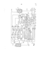
[0011] Para um entendimento mais completo da presente invenção, e para objetivos e vantagens adicionais dela, referência é feita à descrição seguinte tomada junto com os desenhos acompanhantes, em que: Figura 1 é um diagrama esquemático ilustrando controle de infusão em um sistema microcirúrgico oftálmico; Figura 2 é um diagrama esquemático ilustrando controle de infusão e controle de irrigação em um sistema microcirúrgico oftálmico; Figura 3 é uma vista de perspectiva dianteira de um cassete cirúrgico preferido para uso no sistema microcirúrgico oftálmico das Figuras 1 e 2; e Figura 4 é uma vista parcialmente fragmentária de perspectiva dianteira de uma câmara de infusão dupla do cassete cirúrgico da Figura 3. Descrição Detalhada das Concretizações Preferidas[0011] For a more complete understanding of the present invention, and for further purposes and advantages thereof, reference is made to the following description taken together with the accompanying drawings, in which: Figure 1 is a schematic diagram illustrating infusion control in a microsurgical system ophthalmic; Figure 2 is a schematic diagram illustrating infusion control and irrigation control in an ophthalmic microsurgical system; Figure 3 is a front perspective view of a preferred surgical cassette for use in the ophthalmic microsurgical system of Figures 1 and 2; and Figure 4 is a partially fragmentary front perspective view of a dual infusion chamber of the surgical cassette of Figure 3. Detailed Description of the Preferred Embodiments
[0012] As concretizações preferidas da presente invenção e suas vantagens são melhor compreendidas se referindo às Figuras 1-4 dos desenhos, mesmos numerais sendo usados para mesmas partes e correspondentes dos vários desenhos. Como mostrado na Figura 1, o sistema microcirúrgico oftálmico 10 inclui uma manga de pressão 12; uma fonte de infusão 14; uma câmara de infusão dupla 16 tendo uma câmara 16a e uma câmara 16b; sensores de nível de fluido 18 e 20; um sensor de fluxo 22; filtros 24 e 26; um dispositivo cirúrgico 29; um computador ou microprocessador 28; coletores de gás 30 e 32; uma fonte de gás pressurizado 34; válvulas de solenóide proporcionais 36, 38, e 40; válvulas de solenóide de "ligar/desligar" 42, 44, 46, 48, 50, 52, 54; atuadores 56, 58, 60, e 62; e transdutores de pressão 64, 66 e 68. Câmara de infusão dupla 16; sensores de nível de fluido 18 e 20; porções de linhas de fluido de infusão 70, 72, 74, 76, 78, e 80; e porções de linhas de gás 84 e 86 estão preferivelmente dispostas em um cassete cirúrgico 27. Fonte de infusão 14; câmara de infusão dupla 16; sensor de fluxo 22; filtros 24 e 26; e dispositivo cirúrgico 29 estão acoplados fluidicamente por linhas de fluido de infusão 70-80. Fonte de infusão 14, câmara de infusão dupla 16, coletores de gás 30 e 32; fonte de gás pressurizado 34; e atuadores 56, 58, 60 e 62 estão acoplados fluidicamente por linhas de gás 82, 84, 86, 88, 90, 92, 94 e 96. Fonte de infusão 14; sensores de nível de fluido 18-20; sensor de fluxo 22; microprocessador 28; válvulas de solenóide proporcionais 36-40; válvulas de solenóide de ligado/desligado 42-54; atuadores 56-62; e transdutores de pressão acoplados eletricamente 64-68 por interfaces 100, 102, 104, 106, 108, 110, 112, 114, 116, 118, 120, 122, 124, 126, 128, 130 e 132.[0012] The preferred embodiments of the present invention and its advantages are better understood by referring to Figures 1-4 of the drawings, same numerals being used for same and corresponding parts of the various drawings. As shown in Figure 1, the ophthalmic
[0013] Fonte de infusão 14 é preferivelmente uma fonte de infusão flexível. Como mostrado melhor nas Figuras 3-4, a câmara de infusão dupla 16 preferivelmente é formada em uma superfície traseira 27a de cassete cirúrgico 27. Cassete cirúrgico 27 preferivelmente também tem uma superfície de topo 27b e uma superfície de fundo 27c. Câmaras 16a e 16b são preferivelmente separadas por um divisor 16c, e câmaras 16a e 16b não estão acopladas fluidicamente. Câmara de infusão dupla 16 preferivelmente também tem uma superfície superior 16d e uma superfície inferior 16e. Como mostrado melhor nas Figuras 1-2, a câmara 16b tem uma abertura 226 disposta na ou perto da superfície inferior 16e para linha de fluido 74, e a câmara 16a tem uma abertura 228 disposta na ou perto da superfície inferior 16e para linha de fluido 72. Como usado no contexto da sentença precedente, "perto" significa preferivelmente mais perto da superfície inferior 16e do que a um plano transversal passando por um ponto médio entre a superfície inferior 16e e superfície superior 16d, e "perto" significa mais preferivelmente mais perto da superfície inferior 16e do que a um plano transversal passando por um ponto um quarto da distância de superfície inferior 16e e três quartos da distância de superfície superior 16d. Sensores de nível de fluido 18 e 20 podem ser qualquer dispositivo adequado para medir o nível de fluido em câmaras de infusão 16a e 16b, respectivamente. Sensores de nível de fluido 18 e 20 são preferivelmente capazes de medir o nível de fluido em câmaras de infusão 16a e 16b de uma maneira contínua. Sensor de fluxo 22 pode ser qualquer dispositivo adequado para medir a taxa de fluxo de fluido dentro de linha de fluido 80. Sensor de fluxo 22 é preferivelmente um sensor de fluxo não invasivo. Filtros 24 e 26 são filtros micro-bacterianos hidrofóbicos. Um filtro preferido é o filtro de membrana Versapor® (0,8 mícron) disponível de Pall Corporation de East Hills, Nova Iorque. Microprocessador 28 é capaz de implementar controle de realimentação, e preferivelmente controle de PID. Dispositivo cirúrgico 29 pode ser qualquer dispositivo adequado para prover fluido de irrigação cirúrgico ao olho, mas é preferivelmente uma cânula de infusão, uma peça manual de irrigação, e/ou peça manual de irrigação/aspiração. As porções de linhas de fluido 70-80 dispostas em cassete cirúrgico 27, e as porções de linhas de gás 84-46 dispostas em cassete cirúrgico 27 podem ser qualquer linha adequada, tubulação, ou coletor para transportar um fluido, mas são preferivelmente coletores moldados integralmente em cassete cirúrgico 27.[0013]
[0014] Em operação, linhas de fluido 70, 72 e 74; câmaras 16a e 16b; linhas de fluido 76, 78 e 80; e dispositivo cirúrgico 29 são todos preparados com um fluido de irrigação cirúrgico 140 pressurizando a fonte de infusão 14. Fluido de irrigação cirúrgico 140 pode ser qualquer fluido de irrigação cirúrgico adequado para uso oftálmico, tal como, por meio de exemplo, solução de irrigação intra-ocular BSS PLUS® disponível de Alcon Laboratories, Inc.[0014] In operation,
[0015] A pressurização de fonte de infusão 14 é executada preferivelmente por manga de pressão 12. Mais especificamente, o microprocessador 28 envia um sinal de controle para abrir a válvula de solenóide 42 por interface 106 e fechar as válvulas de solenóide 44 e 46 por interfaces 108 e 110, respectivamente. Microprocessador 28 também envia um sinal de controle para abrir a válvula de solenóide proporcional 40 por interface 104 de forma que coletor 30 proveja a quantidade apropriada de ar pressurizado para atuar punho a manga de pressão 12. Transdutor de pressão 68 sente a pressão dentro de linha de gás 82 e provê um sinal correspondente a microprocessador 28 por interface 126. Válvulas de solenóide 48-54 estão inicialmente abertas de forma que o coletor 32 proveja ar pressurizado para atuar os atuadores 56-62 para fechar as linhas de fluido 72-78. Microprocessador 28 envia sinais de controle para fechar as válvulas de solenóide 48-54 por interfaces 114-120. O fechamento de válvulas de solenóide 48-54 atua os atuadores 56-62 para abrir as linhas de fluido 72-78. Depois que todas as câmaras e linhas de fluido estão preparadas, o microprocessador 28 fecha atuadores 56-62 e assim as linhas de fluido 72-78. Alternativamente, a pressurização de fonte de infusão 14 pode ser executada somente por gravidade.[0015] Pressurization of
[0016] Depois de preparar, um usuário então provê uma pressão intraocular desejada a microprocessador 28 por uma entrada 134. Entrada 134 pode ser qualquer dispositivo de entrada adequado, mas é preferivelmente um mostrador de tela de toque ou manopla física. Câmara 16b é preferivelmente a câmara de infusão ativa inicial. Microprocessador 28 envia sinais de controle apropriados para abrir a válvula de solenóide 44 e para abrir a válvula de solenóide proporcional 36 (por interface 100) para prover um nível apropriado de ar pressurizado para câmara 16b. Transdutor de pressão 64 sente a pressão dentro de linha de gás 84 e provê um sinal correspondente a microprocessador 28 por interface 124. Microprocessador 28 também envia um sinal de controle apropriado para abrir o atuador 60 e assim a linha de fluido 78. Câmara 16b provê fluido pressurizado 140 ao olho por linhas de fluido 78 e 80 e dispositivo cirúrgico 29. Sensor de fluxo 22 mede a taxa de fluxo de fluido 140 e provê um sinal correspondente a microprocessador 28 por interface 132. Microprocessador 28 calcula uma pressão intra-ocular predita usando o sinal de sensor de fluxo 22 e informação de impedância determinada empiricamente de sistema microcirúrgico 10. Microprocessador 28 então envia um sinal de controle de realimentação apropriado para válvula de solenóide proporcional 36 para manter a pressão intra-ocular predita na ou perto da pressão intra-ocular desejada durante todas as porções da cirurgia.[0016] After setting, a user then provides a desired intraocular pressure to
[0017] Sensor de nível de fluido 20 monitora continuamente a diminuição no nível de fluido 140 na câmara 16b durante a cirurgia e provê um sinal correspondente a microprocessador 28 por interface 130. Microprocessador 28 executa ajustes para a pressão de ar provida à câmara 16b para acomodar a diferença em altura de cabeça de fluido quando o nível de fluido 140 diminui. Quando o nível de fluido 140 na câmara 16b alcança um nível de limite de fundo, o microprocessador 28 fecha a válvula de solenóide 44 e atuador 60 e abre a válvula de solenóide 46 e atuadores 58 e 62. Câmara 16a é agora a câmara de infusão ativa. Microprocessador 28 envia um sinal de controle apropriado para válvula de solenóide proporcional 38 por interface 102 para prover um nível apropriado de ar pressurizado à câmara 16a. Transdutor de pressão 66 sente a pressão dentro de linha de gás 86 e provê um sinal correspondente a microprocessador 28 por interface 122. Câmara 16a provê fluido pressurizado 140 ao olho por linhas de fluido 76 e 80 e dispositivo cirúrgico 29. Sensor de fluxo 22 mede a taxa de fluxo de fluido 140 e provê um sinal correspondente a microprocessador 28 por interface 132. Microprocessador 28 calcula a pressão intra-ocular predita como descrito acima e envia um sinal de realimentação apropriado à válvula de solenóide proporcional 38 para manter a pressão intra-ocular predita na ou perto da pressão intra-ocular desejada durante todas as porções da cirurgia. Microprocessador 28 fecha o atuador 58 e linha de fluido 74 uma vez que câmara 16b seja re-enchida com fluido 140.[0017]
[0018] Sensor de nível de fluido 18 monitora continuamente a diminuição no nível de fluido 140 na câmara 16a durante a cirurgia e provê um sinal correspondente a microprocessador 28 por interface 128. Microprocessador 28 executa ajustes para a pressão de ar provida à câmara 16a para acomodar a diferença em altura de cabeça de fluido quando o nível de fluido 140 diminui. Quando o nível de fluido 140 na câmara 16a alcança um nível de limite de fundo, o microprocessador 28 comuta a câmara 16b para infusão ativa, faz a câmara 16a inativa, e re-enche a câmara 16a com fluido 140 por linha de fluido 72. Este ciclismo entre câmaras 16b e 16a continua ao longo da cirurgia.[0018]
[0019] A fonte de infusão 14 é monitorada preferivelmente por um sensor de nível de fluido (não mostrado) capaz de prover um sinal a microprocessador 28 por interface 112 quando a fonte 14 alcança um limite próximo a vazio. Câmaras 16a e 16b também preferivelmente cada uma tem um volume que habilita a fonte de infusão 14 ser trocada, quando próxima a vazia, sem interromper o procedimento cirúrgico. Mais especificamente, as câmaras 16a e 16b preferivelmente cada uma tem um volume de cerca de 30 cm3. Tal volume permite cerca de dois minutos para uma fonte de infusão próxima a vazia 14 ser trocada durante condições de fluxo máximo (por exemplo 'vitrectomy' de núcleo). Além disso, desde que as linhas de fluido 72 e 74 estão acopladas fluidicamente às câmaras 16a e 16b, respectivamente, na ou perto da superfície inferior 16e, uma vez a fonte de infusão 14 é trocada, todas as bolhas de ar dentro de linhas de fluido 70, 72, e 74 serão "retiradas" automaticamente quando a câmara inativa 16a ou 16b re-enche, sem a necessidade por re-preparo.[0019] The
[0020] No caso de falha de qualquer uma de câmaras 16a ou 16b, o microprocessador 28 preferivelmente pode continuar a cirurgia com só uma câmara ativa. No caso de falha de ambas as câmaras 16a e 16b, o microprocessador 28 preferivelmente pode continuar a cirurgia usando só a fonte de infusão 14.[0020] In the event of failure of either
[0021] Figura 2 mostra um sistema microcirúrgico oftálmico modificado 10a. Sistema microcirúrgico 10a é semelhante a sistema microcirúrgico 10, exceto que tem um sistema de irrigação além do sistema de infusão descrito acima para sistema 10. Mais especificamente, o sistema 10a é idêntico a sistema 10, exceto que o sistema 10a também inclui uma fonte de irrigação 200; linhas de fluido 202 e 206; linhas de gás 208 e 216; válvulas de solenóide 210 e 218; atuadores 214 e 222; interfaces elétricas 212 e 220; e um dispositivo cirúrgico 224. Como mostrado na Figura 2, a fonte de irrigação 200 é pressurizada somente por gravidade. As porções de linhas de fluido 202 e 206 dispostas no cassete cirúrgico 27, e as porções de linhas de gás 208 e 216 dispostas no cassete cirúrgico 27, podem ser qualquer linha adequada, tubulação, ou coletor para transportar um fluido, mas são preferivelmente coletores moldados integralmente no cassete cirúrgico 27. Como será apreciado por alguém de habilidade ordinária na técnica, o sistema microcirúrgico 10a permite a fluido de irrigação cirúrgico 140 ser entregue a dispositivo cirúrgico 29 por linha de fluido 80 (infusão), e fluido de irrigação cirúrgico 140 ser entregue a dispositivo cirúrgico 224 por linha de fluido 206 (irrigação), independentemente. Microprocessador 28 pode calcular informação de fluxo para fluido 140 dentro de linha de fluido 206 monitorando continuamente a mudança volumétrica de fluido dentro de câmara 16b, como indicado por sensor de fluido 20.[0021] Figure 2 shows a modified ophthalmic
[0022] Do anterior pode ser apreciado que a presente invenção provê um método melhorado de controlar pressão intra-ocular com um sistema microcirúrgico. A presente invenção é ilustrada aqui através de exemplo, e várias modificações podem ser feitas por uma pessoa de habilidade ordinária na técnica. Por exemplo, enquanto a presente invenção é descrita relativa a controlar pressão intra-ocular em um sistema microcirúrgico oftálmico, também é aplicável a controlar pressão dentro do tecido operativo durante outros tipos de microcirurgia.[0022] From the foregoing it can be appreciated that the present invention provides an improved method of controlling intraocular pressure with a microsurgical system. The present invention is illustrated here by way of example, and various modifications can be made by a person of ordinary skill in the art. For example, while the present invention is described relating to controlling intraocular pressure in an ophthalmic microsurgical system, it is also applicable to controlling pressure within operative tissue during other types of microsurgery.
[0023] É acreditado que a operação e construção da presente invenção serão aparentes da descrição precedente. Enquanto o aparelho e métodos mostrados ou descritos acima foram caracterizados como sendo preferidos, várias mudanças e modificações podem ser feitas neles sem partir do espírito e extensão da invenção como definida nas reivindicações seguintes.[0023] It is believed that the operation and construction of the present invention will be apparent from the foregoing description. While the apparatus and methods shown or described above have been characterized as being preferred, various changes and modifications can be made thereto without departing from the spirit and scope of the invention as defined in the following claims.
Claims (7)
Applications Claiming Priority (3)
| Application Number | Priority Date | Filing Date | Title |
|---|---|---|---|
| US11/237,568 US7713237B2 (en) | 2005-09-28 | 2005-09-28 | Surgical cassette for intraocular pressure control |
| US11/237568 | 2005-09-28 | ||
| PCT/US2006/033909 WO2007037900A2 (en) | 2005-09-28 | 2006-08-30 | Surgical cassette for intraocular pressure control |
Publications (3)
| Publication Number | Publication Date |
|---|---|
| BRPI0616435A2 BRPI0616435A2 (en) | 2012-12-25 |
| BRPI0616435B1 true BRPI0616435B1 (en) | 2023-01-24 |
| BRPI0616435B8 BRPI0616435B8 (en) | 2023-02-07 |
Family
ID=37895092
Family Applications (1)
| Application Number | Title | Priority Date | Filing Date |
|---|---|---|---|
| BRPI0616435A BRPI0616435B8 (en) | 2005-09-28 | 2006-08-30 | SURGICAL CASSETTE |
Country Status (21)
| Country | Link |
|---|---|
| US (2) | US7713237B2 (en) |
| EP (2) | EP2286851A3 (en) |
| JP (1) | JP5209483B2 (en) |
| KR (1) | KR101223992B1 (en) |
| CN (1) | CN101384296B (en) |
| AR (1) | AR058672A1 (en) |
| AT (1) | ATE491495T1 (en) |
| AU (1) | AU2006295262B2 (en) |
| BR (1) | BRPI0616435B8 (en) |
| CA (1) | CA2620367C (en) |
| CY (1) | CY1111888T1 (en) |
| DE (1) | DE602006018992D1 (en) |
| DK (1) | DK1960032T3 (en) |
| ES (1) | ES2356561T3 (en) |
| MX (1) | MX2008003013A (en) |
| PL (1) | PL1960032T3 (en) |
| PT (1) | PT1960032E (en) |
| RU (1) | RU2421196C2 (en) |
| SI (1) | SI1960032T1 (en) |
| TW (1) | TWI401067B (en) |
| WO (1) | WO2007037900A2 (en) |
Families Citing this family (29)
| Publication number | Priority date | Publication date | Assignee | Title |
|---|---|---|---|---|
| US7604615B2 (en) * | 2006-03-20 | 2009-10-20 | Alcon, Inc. | Surgical cassette with bubble separating structure |
| US7559914B2 (en) * | 2005-12-14 | 2009-07-14 | Alcon, Inc. | Priming a microsurgical system |
| US7764370B2 (en) * | 2006-06-30 | 2010-07-27 | Alcon, Inc. | System and method to zero chambers in a surgical cassette |
| US20080147023A1 (en) * | 2006-12-18 | 2008-06-19 | Mark Alan Hopkins | System and method for controlling fluid flow in an aspiration chamber |
| US8491565B2 (en) * | 2007-07-20 | 2013-07-23 | Medingo Ltd. | Collapsible reservoir for use with a delivery device |
| GB0821180D0 (en) | 2008-11-20 | 2008-12-24 | Surgicaledge Systems Ltd | Apparatus and method of fluid delivery |
| US8162919B2 (en) * | 2008-12-08 | 2012-04-24 | Bausch & Lomb Incorporated | Flow control system based on leakage |
| US9517162B2 (en) | 2011-11-30 | 2016-12-13 | Alcon Research, Ltd. | Retinal surgery |
| EP3081239B8 (en) | 2011-12-08 | 2020-03-11 | Alcon Inc. | Selectively moveable valve elements for aspiration and irrigation circuits |
| US9629523B2 (en) | 2012-06-27 | 2017-04-25 | Camplex, Inc. | Binocular viewing assembly for a surgical visualization system |
| US9642606B2 (en) | 2012-06-27 | 2017-05-09 | Camplex, Inc. | Surgical visualization system |
| NL2009424C2 (en) | 2012-09-06 | 2014-03-10 | D O R C Dutch Ophthalmic Res Ct International B V | Irrigation/aspiration system, cartridge, pump unit, surgical machine, method for controlling. |
| US9132229B2 (en) | 2012-09-13 | 2015-09-15 | Alcon Research, Ltd. | System and method of priming a surgical cassette |
| US9089398B2 (en) | 2012-09-17 | 2015-07-28 | Alcon Research, Ltd. | Aspiration cassette with gas and debris management |
| USD698019S1 (en) | 2013-03-05 | 2014-01-21 | Alcon Research, Ltd. | Ophthalmic surgical cassette |
| US9549850B2 (en) | 2013-04-26 | 2017-01-24 | Novartis Ag | Partial venting system for occlusion surge mitigation |
| WO2014189969A1 (en) | 2013-05-21 | 2014-11-27 | Camplex, Inc. | Surgical visualization systems |
| WO2015042483A2 (en) | 2013-09-20 | 2015-03-26 | Camplex, Inc. | Surgical visualization systems |
| WO2015042460A1 (en) | 2013-09-20 | 2015-03-26 | Camplex, Inc. | Surgical visualization systems and displays |
| WO2016090336A1 (en) | 2014-12-05 | 2016-06-09 | Camplex, Inc. | Surgical visualization systems and displays |
| WO2016154589A1 (en) | 2015-03-25 | 2016-09-29 | Camplex, Inc. | Surgical visualization systems and displays |
| US10966798B2 (en) | 2015-11-25 | 2021-04-06 | Camplex, Inc. | Surgical visualization systems and displays |
| US11051978B2 (en) | 2016-05-10 | 2021-07-06 | Alcon Inc. | Automated aspiration throttling in vitreoretinal surgery |
| CN109152657B (en) | 2016-05-17 | 2024-02-27 | 爱尔康公司 | Automated viscous fluid control in vitreoretinal surgery |
| US10918455B2 (en) | 2017-05-08 | 2021-02-16 | Camplex, Inc. | Variable light source |
| US11116878B2 (en) | 2017-11-16 | 2021-09-14 | Alcon Inc. | Fluidics aspiration system |
| JP7342011B2 (en) | 2018-02-22 | 2023-09-11 | アルコン インコーポレイティド | Gas mixing system and method in ophthalmic surgical equipment |
| US11642243B2 (en) | 2018-12-10 | 2023-05-09 | Alcon Inc. | Methods of solenoid valve control optimization |
| US20210178031A1 (en) * | 2019-12-17 | 2021-06-17 | Johnson & Johnson Surgical Vision, Inc. | Rotary valve configuration for a surgical cassette |
Family Cites Families (78)
| Publication number | Priority date | Publication date | Assignee | Title |
|---|---|---|---|---|
| US352106A (en) * | 1886-11-02 | benton | ||
| US375553A (en) * | 1887-12-27 | Carriage-top | ||
| US380550A (en) * | 1888-04-03 | clowes | ||
| US3902495A (en) | 1974-01-28 | 1975-09-02 | Cavitron Corp | Flow control system |
| CA1068574A (en) | 1974-01-28 | 1979-12-25 | Steven N. Weiss | Flow control system |
| US4936131A (en) * | 1980-07-30 | 1990-06-26 | Gray John C | Production of threaded metal rods for making U-bolts |
| US4475904A (en) * | 1982-12-29 | 1984-10-09 | Medical Instrument Dev. Labs., Inc. | Fast response vacuum aspiration collection system |
| US4713051A (en) * | 1985-05-21 | 1987-12-15 | Coopervision, Inc. | Cassette for surgical irrigation and aspiration and sterile package therefor |
| US4935005A (en) * | 1985-06-05 | 1990-06-19 | Nestle, S.A. | Opthalmic fluid flow control system |
| US4832685A (en) * | 1985-06-05 | 1989-05-23 | Coopervision, Inc. | Fluid flow control system and connecting fitting therefor |
| US4841984A (en) * | 1985-09-16 | 1989-06-27 | Armoor Ophthalmics, Inc. | Fluid-carrying components of apparatus for automatic control of intraocular pressure |
| CA1280326C (en) * | 1985-09-25 | 1991-02-19 | Leif Joakim Sundblom | Fast response tubeless vacuum aspiration collection cassette |
| US4750643A (en) * | 1986-08-04 | 1988-06-14 | Sugrin Surgical Instrumentation, Inc. | Sterile fluid dispensing system and method |
| US5125891A (en) * | 1987-04-27 | 1992-06-30 | Site Microsurgical Systems, Inc. | Disposable vacuum/peristaltic pump cassette system |
| US4813927A (en) * | 1987-09-22 | 1989-03-21 | Vitreoretinal Development, Inc. | Parallel infusion apparatus and method |
| US5032111A (en) * | 1987-09-22 | 1991-07-16 | Vitreoretinal Development, Inc. | Method and apparatus for ocular perfusion |
| US5047009A (en) * | 1987-09-22 | 1991-09-10 | Vitreoretinal Development, Inc. | Method and apparatus for ocular perfusion |
| US4900301A (en) * | 1987-09-22 | 1990-02-13 | Vitreoretinal Development, Inc. | Method for ocular perfusion |
| US4963131A (en) | 1989-03-16 | 1990-10-16 | Surgin Surgical Instrumentation, Inc. | Disposable cassette for ophthalmic surgery applications |
| US5163900A (en) * | 1989-03-16 | 1992-11-17 | Surgin Surgical Instrumentation, Inc. | Disposable cassette systems |
| US5041096A (en) * | 1989-10-27 | 1991-08-20 | Nestle, S.A. | Fluid handling method and system and fluid interface apparatus usable therewith |
| US5098037A (en) * | 1989-11-06 | 1992-03-24 | The B. F. Goodrich Company | Structural airfoil having integral expulsive system |
| US5106366A (en) * | 1990-03-08 | 1992-04-21 | Nestle, S.A. | Medical fluid cassette and control system |
| US5060825A (en) | 1990-05-04 | 1991-10-29 | Sultan Chemists, Inc. | Irrigation system and method for delivering a selected one of multiple liquid solutions to a treatment site |
| JPH04259468A (en) * | 1991-02-12 | 1992-09-16 | Toray Ind Inc | Dialysis device with moisture removal control |
| DE69228410T2 (en) * | 1991-08-21 | 1999-07-08 | Smith & Nephew Inc | Liquid treatment system |
| US5267956A (en) * | 1992-02-05 | 1993-12-07 | Alcon Surgical, Inc. | Surgical cassette |
| US5499969A (en) * | 1992-02-05 | 1996-03-19 | Nestle S.A. | Microsurgical cassette |
| AU4394793A (en) | 1992-06-03 | 1993-12-30 | Allergan, Inc. | Tubing management system |
| USD352106S (en) * | 1992-09-02 | 1994-11-01 | Alcon Laboratories, Inc. | Surgical console for ophthalmic surgery |
| US5776104A (en) * | 1993-06-01 | 1998-07-07 | Guignard; Mireille | Device for supplying a liquid to a body cavity of a person or an animal and subjecting it to a determined pressure |
| JP3162723B2 (en) * | 1994-01-28 | 2001-05-08 | アラーガン・セイルズ・インコーポレイテッド | Apparatus for controlling fluid irrigation and fluid aspiration in ophthalmic surgery |
| US5591127A (en) * | 1994-01-28 | 1997-01-07 | Barwick, Jr.; Billie J. | Phacoemulsification method and apparatus |
| JP3679143B2 (en) * | 1994-06-30 | 2005-08-03 | 株式会社ニデック | Perfusion suction device |
| US5582601A (en) * | 1994-09-12 | 1996-12-10 | Surgin Surgical Instrumentation, Inc. | Cassette for receiving aspirated fluids |
| EP0717970A1 (en) * | 1994-12-20 | 1996-06-26 | GRIESHABER & CO. AG SCHAFFHAUSEN | Opthalmic aspiration and irrigation device and its operation procedure |
| US5810766A (en) * | 1995-02-28 | 1998-09-22 | Chiron Vision Corporation | Infusion/aspiration apparatus with removable cassette |
| US5620312A (en) * | 1995-03-06 | 1997-04-15 | Sabratek Corporation | Infusion pump with dual-latching mechanism |
| USD380550S (en) * | 1995-11-14 | 1997-07-01 | Alcon Laboratories, Inc. | Surgical console |
| US5588815A (en) * | 1995-11-15 | 1996-12-31 | Alcon Laboratories, Inc. | Surgical cassette loading and unloading system |
| US5800396A (en) * | 1995-11-15 | 1998-09-01 | Alcon Laboratories, Inc. | Surgical cassette adapter |
| USD375553S (en) * | 1995-11-15 | 1996-11-12 | Alcon Laboratories, Inc. | Surgical cassette adapter |
| US6059544A (en) | 1995-12-01 | 2000-05-09 | Alcon Laboratories, Inc. | Identification system for a surgical cassette |
| CA2186805C (en) * | 1995-12-01 | 2001-03-27 | Christopher C. Jung | Apparatus and method for sensing fluid level |
| US5899674A (en) * | 1995-12-01 | 1999-05-04 | Alcon Laboratories, Inc. | Indentification system for a surgical cassette |
| US5676530A (en) * | 1996-01-24 | 1997-10-14 | Alcon Laboratories, Inc. | Surgical cassette latching mechanism |
| JP3860260B2 (en) * | 1996-07-31 | 2006-12-20 | 株式会社ニデック | Perfusion suction device |
| US5865764A (en) * | 1996-12-30 | 1999-02-02 | Armoor Opthalmics, Inc. | Device and method for noninvasive measurement of internal pressure within body cavities |
| US5897524A (en) * | 1997-03-24 | 1999-04-27 | Wortrich; Theodore S. | Compact cassette for ophthalmic surgery |
| US7776014B2 (en) * | 1998-01-29 | 2010-08-17 | Peter Visconti | Disposable surgical suction/irrigation trumpet valve tube cassette |
| US6159160A (en) | 1998-03-26 | 2000-12-12 | Ethicon, Inc. | System and method for controlled infusion and pressure monitoring |
| US6986753B2 (en) * | 1998-05-21 | 2006-01-17 | Buivision | Constant ocular pressure active infusion system |
| JP3877874B2 (en) * | 1998-05-29 | 2007-02-07 | 株式会社ニデック | Perfusion suction device and perfusion suction cassette |
| DE19852574A1 (en) | 1998-11-06 | 2000-05-11 | Aesculap Meditec Gmbh | Medical instrument for phacoemulsification |
| US6962488B2 (en) * | 1999-11-10 | 2005-11-08 | Alcon, Inc. | Surgical cassette having an aspiration pressure sensor |
| US6293926B1 (en) * | 1999-11-10 | 2001-09-25 | Alcon Universal Ltd. | Peristaltic pump and cassette |
| US6902542B2 (en) * | 2002-05-28 | 2005-06-07 | Alcon, Inc. | Identification system for a surgical cassette |
| US6261283B1 (en) * | 1999-08-31 | 2001-07-17 | Alcon Universal Ltd. | Liquid venting surgical system and cassette |
| US6740074B2 (en) * | 1999-08-31 | 2004-05-25 | Alcon, Inc. | Liquid venting surgical cassette |
| US20040253129A1 (en) * | 1999-08-31 | 2004-12-16 | Sorensen Gary P. | Liquid venting surgical cassette |
| US7204821B1 (en) * | 2000-01-31 | 2007-04-17 | Ethicon, Inc. | Surgical fluid management system with suction control |
| WO2001060429A2 (en) * | 2000-02-17 | 2001-08-23 | The Johns Hopkins University Applied Physics Laboratory | Vestibular irrigator test system (vits) |
| JP4382322B2 (en) * | 2000-03-09 | 2009-12-09 | カリディアンビーシーティ、インコーポレイテッド | Extracorporeal blood treatment equipment |
| US6503062B1 (en) * | 2000-07-10 | 2003-01-07 | Deka Products Limited Partnership | Method for regulating fluid pump pressure |
| US6485451B1 (en) * | 2000-08-02 | 2002-11-26 | Welch Allyn, Inc. | Body cavity irrigation system |
| DE60125806T2 (en) * | 2000-09-22 | 2007-10-11 | C.R. Bard, Inc. | SURGICAL DISHWASHER |
| US6561999B1 (en) * | 2000-09-29 | 2003-05-13 | Alcon Universal Ltd. | Surgical cassette and consumables for combined ophthalmic surgical procedure |
| US6579255B2 (en) * | 2001-07-31 | 2003-06-17 | Advanced Medical Optics, Inc. | Pressurized flow of fluid into the eye using pump and pressure measurement system |
| US6733491B2 (en) * | 2001-09-07 | 2004-05-11 | Advanced Medical Optics | Cataract extraction apparatus and method |
| KR100824086B1 (en) * | 2001-09-12 | 2008-04-21 | 제너럴 일렉트릭 캄파니 | Bumper beam with crush cans |
| ITRM20010669A1 (en) * | 2001-11-09 | 2003-05-09 | Optikon 2000 Spa | SUCTION INFUSION BOX (I / A) WITH SUCTION SYSTEM BOTH VIA PERISTALTIC PUMP OR OTHERWISE VOLUMETRIC THAN USING PR PUMP |
| US6634237B2 (en) | 2001-11-30 | 2003-10-21 | Bausch & Lomb Incorporated | Collection reservoir for use with flow meter control system |
| US20030101825A1 (en) | 2001-11-30 | 2003-06-05 | Neubert William J. | Aspiration tube for use with flow meter control system |
| US6599277B2 (en) | 2001-11-30 | 2003-07-29 | Bausch & Lomb Incorporated | Aspiration flow meter and control |
| CA2479023A1 (en) | 2002-03-19 | 2003-10-02 | S.K. Pharmaceuticals, Inc. | Methods and systems for performing vitrectomy with continuous perfluorocarbon infusion |
| US7070578B2 (en) | 2002-04-25 | 2006-07-04 | Alcon, Inc. | Surgical cassette latching mechanism |
| US20030225363A1 (en) * | 2002-05-28 | 2003-12-04 | Raphael Gordon | Surgical cassette |
| US20050285025A1 (en) | 2004-06-29 | 2005-12-29 | Mikhail Boukhny | Optical noninvasive pressure sensor |
-
2005
- 2005-09-28 US US11/237,568 patent/US7713237B2/en active Active
-
2006
- 2006-08-30 PT PT06790101T patent/PT1960032E/en unknown
- 2006-08-30 PL PL06790101T patent/PL1960032T3/en unknown
- 2006-08-30 SI SI200630939T patent/SI1960032T1/en unknown
- 2006-08-30 DE DE602006018992T patent/DE602006018992D1/en active Active
- 2006-08-30 BR BRPI0616435A patent/BRPI0616435B8/en active IP Right Grant
- 2006-08-30 JP JP2008533365A patent/JP5209483B2/en active Active
- 2006-08-30 EP EP10194426A patent/EP2286851A3/en not_active Withdrawn
- 2006-08-30 EP EP06790101A patent/EP1960032B9/en active Active
- 2006-08-30 CN CN200680036179XA patent/CN101384296B/en active Active
- 2006-08-30 WO PCT/US2006/033909 patent/WO2007037900A2/en active Application Filing
- 2006-08-30 DK DK06790101.7T patent/DK1960032T3/en active
- 2006-08-30 ES ES06790101T patent/ES2356561T3/en active Active
- 2006-08-30 RU RU2008116572/14A patent/RU2421196C2/en active
- 2006-08-30 AU AU2006295262A patent/AU2006295262B2/en active Active
- 2006-08-30 CA CA2620367A patent/CA2620367C/en active Active
- 2006-08-30 MX MX2008003013A patent/MX2008003013A/en active IP Right Grant
- 2006-08-30 KR KR1020087009078A patent/KR101223992B1/en active IP Right Grant
- 2006-08-30 AT AT06790101T patent/ATE491495T1/en active
- 2006-09-08 TW TW095133231A patent/TWI401067B/en not_active IP Right Cessation
- 2006-09-25 AR ARP060104171A patent/AR058672A1/en not_active Application Discontinuation
-
2010
- 2010-03-31 US US12/750,787 patent/US7896839B2/en active Active
-
2011
- 2011-03-02 CY CY20111100243T patent/CY1111888T1/en unknown
Also Published As
Similar Documents
| Publication | Publication Date | Title |
|---|---|---|
| BRPI0616435B1 (en) | SURGICAL CASSETTE | |
| EP1928538B1 (en) | Intraocular pressure control | |
| TWI401068B (en) | Surgical cassette with multi area fluid chamber | |
| US20070293844A1 (en) | Intraocular pressure control | |
| JP5410957B2 (en) | Surgical cassette with multi-region fluid chamber | |
| AU2012251920B2 (en) | Intraocular pressure control |
Legal Events
| Date | Code | Title | Description |
|---|---|---|---|
| B06G | Technical and formal requirements: other requirements [chapter 6.7 patent gazette] |
Free format text: SOLICITA-SE A REGULARIZACAO DA PROCURACAO, UMA VEZ QUE BASEADO NO ARTIGO 216 1O DA LPI, O DOCUMENTO DE PROCURACAO DEVE SER APRESENTADO NO ORIGINAL, TRASLADO OU FOTOCOPIA AUTENTICADA. |
|
| B15K | Others concerning applications: alteration of classification |
Ipc: A61M 3/02 (2006.01), A61M 1/00 (2006.01) |
|
| B07A | Application suspended after technical examination (opinion) [chapter 7.1 patent gazette] | ||
| B09B | Patent application refused [chapter 9.2 patent gazette] | ||
| B12B | Appeal against refusal [chapter 12.2 patent gazette] | ||
| B25A | Requested transfer of rights approved |
Owner name: NOVARTIS AG (CH) |
|
| B25A | Requested transfer of rights approved |
Owner name: ALCON INC. (CH) |
|
| B16A | Patent or certificate of addition of invention granted [chapter 16.1 patent gazette] |
Free format text: PRAZO DE VALIDADE: 20 (VINTE) ANOS CONTADOS A PARTIR DE 30/08/2006, OBSERVADAS AS CONDICOES LEGAIS. PATENTE CONCEDIDA CONFORME ADI 5.529/DF, QUE DETERMINA A ALTERACAO DO PRAZO DE CONCESSAO. |
|
| B16C | Correction of notification of the grant [chapter 16.3 patent gazette] |
Free format text: REFERENTE A RPI 2716 DE 24/01/2023, QUANTO AO ITEM (73) CIDADANIA. |