BRPI0601560B1 - shaft retaining assembly for differentials - Google Patents
shaft retaining assembly for differentials Download PDFInfo
- Publication number
- BRPI0601560B1 BRPI0601560B1 BRPI0601560-3A BRPI0601560A BRPI0601560B1 BR PI0601560 B1 BRPI0601560 B1 BR PI0601560B1 BR PI0601560 A BRPI0601560 A BR PI0601560A BR PI0601560 B1 BRPI0601560 B1 BR PI0601560B1
- Authority
- BR
- Brazil
- Prior art keywords
- differential
- spacer
- ring
- chamber
- pair
- Prior art date
Links
Images


Classifications
-
- F—MECHANICAL ENGINEERING; LIGHTING; HEATING; WEAPONS; BLASTING
- F16—ENGINEERING ELEMENTS AND UNITS; GENERAL MEASURES FOR PRODUCING AND MAINTAINING EFFECTIVE FUNCTIONING OF MACHINES OR INSTALLATIONS; THERMAL INSULATION IN GENERAL
- F16H—GEARING
- F16H48/00—Differential gearings
- F16H48/20—Arrangements for suppressing or influencing the differential action, e.g. locking devices
- F16H48/28—Arrangements for suppressing or influencing the differential action, e.g. locking devices using self-locking gears or self-braking gears
- F16H48/285—Arrangements for suppressing or influencing the differential action, e.g. locking devices using self-locking gears or self-braking gears with self-braking intermeshing gears having parallel axes and having worms or helical teeth
-
- F—MECHANICAL ENGINEERING; LIGHTING; HEATING; WEAPONS; BLASTING
- F16—ENGINEERING ELEMENTS AND UNITS; GENERAL MEASURES FOR PRODUCING AND MAINTAINING EFFECTIVE FUNCTIONING OF MACHINES OR INSTALLATIONS; THERMAL INSULATION IN GENERAL
- F16H—GEARING
- F16H48/00—Differential gearings
- F16H48/12—Differential gearings without gears having orbital motion
Abstract
MONTAGEM DE RETENÇÃO DE EIXO PARA DIFERENCIAIS E MÉTODO DE MONTAGEM. Um montagem diferencial inclui um alojamento diferencial que define uma câmara e um par de aberturas alinhadas que se comunicam com a câmara. Um par de eixos de saída estende-se através das aberturas no alojamento diferencial e inclui segmentos terminais localizados dentro da câmara. Um par de engrenagens laterais é posicionado dentro da câmara e fixado aos segmentos terminais do eixo da saída. Conjuntos pareados de pinhão são montados, de forma rotacionável, dentro do alojamento diferencial e posicionados em encaixe enredado um com o outro e com uma das engrenagens laterais. Uma montagem de retenção interconecta os segmentos terminais e inclui um espaçador tendo ma teia posicionada entre e paredes abrangendo parcialmente os segmentos terminais. A montagem de retenção inclui um anel que circunda o espaçador para reter seletivamente e permitir remoção dos clipes encaixados com os segmentos terminais.AXLE RETENTION ASSEMBLY FOR DIFFERENTIALS AND ASSEMBLY METHOD. A differential mount includes a differential housing that defines a chamber and a pair of aligned openings that communicate with the chamber. A pair of output shafts extends through the openings in the differential housing and includes end segments located inside the chamber. A pair of side gears is positioned inside the chamber and attached to the end segments of the output shaft. Paired sets of pinions are rotatably mounted inside the differential housing and positioned in a meshed connection with each other and with one of the side gears. A retaining assembly interconnects the end segments and includes a spacer having web positioned between and walls partially covering the end segments. The retaining assembly includes a ring that surrounds the spacer to selectively retain and allow removal of the clips fitted with the end segments.
Description
[001] A presente invenção refere-se a diferenciais para uso em linhas de acionamento automotivas e, mais particularmente, a uma montagem de retenção de eixo para um diferencial de engrenagem helicoidal.[001] The present invention relates to differentials for use in automotive drive lines and, more particularly, to an axle retaining assembly for a helical gear differential.
[002] Diferenciais do tipo usado em linhas de acionamento automotivas, em geral, incluem um conjunto de engrenagens planetárias suportado dentro de um alojamento diferencial para facilitar rotação relativa (isto é, diferenciação de velocidade) entre um par de eixos de saída. Diferenciais de engrenagens helicoidais, o conjunto de engrenagem, tipicamente, inclui engrenagens laterais helicoidais fixadas à extremidade dos eixos de saída que estão enredados com conjuntos pareados de pinhões helicoidais apoiados em cavidades de engrenagem formadas no alojamento diferencial. Uma vez que as cavidades de engrenagem estão paralelas ao eixo de rotação do alojamento diferencial, os pinhões rodam nos eixos que estão paralelos ao eixo comum dos eixos de saída e as engrenagens laterais. Em resposta à diferenciação de velocidade entre os eixos de saída, o torque transmitido através do encaixe enredado das engrenagens laterais e pinhões gera forças de impulso que são exercidas pelos componentes da engrenagem contra a superfície da parede das cavidades de engrenagem e outras superfícies de impulso dentro do alojamento diferencial para limitar, de forma friccionada, tal diferenciação de velocidade e torque de proporção entre os eixos de saída.[002] Differentials of the type used in automotive drive lines, in general, include a set of planetary gears supported within a differential housing to facilitate relative rotation (that is, speed differentiation) between a pair of output shafts. Helical gear differentials, the gear set typically includes helical side gears attached to the end of the output shafts that are entangled with paired sets of helical pinions supported in gear cavities formed in the differential housing. Since the gear cavities are parallel to the axis of rotation of the differential housing, the pinions rotate on the axes that are parallel to the common axis of the output shafts and the side gears. In response to the speed differentiation between the output shafts, the torque transmitted through the entangled fit of the side gears and pinions generates thrust forces that are exerted by the gear components against the wall surface of the gear cavities and other thrust surfaces within the differential housing to limit, in a frictional way, such differentiation of speed and torque of proportion between the output shafts.
[003] Um problema associado com alguns diferenciais de engrenagem helicoidal é a separação axial dos eixos de saída dentro do alojamento diferencial em relação às engrenagens laterais. Um problema relacionado envolve a manutenção de uma relação espacial adequada entre as extremidades dos eixos de saída. Mais tipicamente, um retentor de clipe tipo C montado em ranhuras são utilizados para reter as extremidades dos eixos de saída em relação às engrenagens laterais. Além disso, também é conhecido instalar espaçadores (isto é, pinos blocos, placas de impulso etc.) no alojamento diferencial entre as extremidades terminais dos eixos de saída. Devido ao acesso limitado ao conjunto de engrenagem, no entanto, tais espaçadores podem ser de difícil instalação dentro do alojamento diferencial. Exemplos de espaçadores conhecidos e disposições de clipe em diferenciais helicoidais são mostrados nas patentes nos US 4,495,835, US 4,512,221, US 5, 221,238, US 5,554,081, US 5,671,640 e US 5,984,823. A patente US 5,221,238 representa o estado da arte mais próximo[003] A problem associated with some helical gear differentials is the axial separation of the output shafts within the differential housing in relation to the side gears. A related problem involves maintaining an adequate spatial relationship between the ends of the output axes. More typically, a groove-mounted type C clip retainer is used to retain the ends of the output shafts in relation to the side gears. In addition, it is also known to install spacers (ie, block pins, thrust plates, etc.) in the differential housing between the end ends of the output shafts. Due to limited access to the gear assembly, however, such spacers can be difficult to install within the differential housing. Examples of known spacers and clip arrangements on helical differentials are shown in the patents in US 4,495,835, US 4,512,221, US 5, 221,238, US 5,554,081, US 5,671,640 and US 5,984,823. US patent 5,221,238 represents the closest state of the art
[004] Assim, é um objetivo da presente invenção fornecer uma montagem de retenção para uso em um diferencial helicoidal que é superior aos dispositivos de espaçamento e retenção de clipe tipo C em termos de função e montagem simplificada.[004] Thus, it is an objective of the present invention to provide a retention assembly for use in a helical differential that is superior to type C clip spacing and retention devices in terms of function and simplified assembly.
[005] A presente invenção é direcionada a um diferencial que compreende um alojamento que define uma câmara e um par de aberturas alinhadas. Um par de eixos de saída tendo segmentos terminais que se estendem através das aberturas alinhadas no alojamento é posicionado na câmara. Um conjunto de engrenagem é operável para transferir energia rotacional do alojamento para os eixos de saída, enquanto permite diferenciação de velocidade entre os eixos de saída. O conjunto de engrenagem é retido na câmara e inclui um par de engrenagens laterais engrenadas, de forma acionável, com os seguimentos terminais dos eixos de saída. Uma montagem de retenção é posicionada dentro da câmara e é operável para manter a posição axial dos segmentos terminais dos eixos de saída. A montagem de retenção inclui um anel tendo janelas, um espaçador tendo recessos e um prendedor, o recesso sendo em recebimento dos segmentos terminais, o espaçador sendo rotacionável dentro do anel para alinhar os recessos com as janelas a fim de permitir que um par de clipes passe através das mesmas e em encaixe com os segmentos terminais. O prendedor é operável para interconectar o anel e o espaçador quando os recessos estão fora de alinhamento com as janelas, capturando, desse modo, o par de clipes dentro dos recessos do espaçador.[005] The present invention is directed to a differential comprising a housing that defines a chamber and a pair of aligned openings. A pair of output shafts having end segments that extend through the aligned openings in the housing is positioned in the chamber. A gear set is operable to transfer rotational energy from the housing to the output shafts, while allowing speed differentiation between the output shafts. The gear set is retained in the chamber and includes a pair of side gears geared, in an actionable way, with the terminal segments of the output shafts. A retaining assembly is positioned inside the chamber and is operable to maintain the axial position of the end segments of the output shafts. The retainer assembly includes a ring having windows, a spacer having recesses and a fastener, the recess being receiving end segments, the spacer being rotatable within the ring to align the recesses with the windows to allow a pair of clips pass through them and fit with the end segments. The fastener is operable to interconnect the ring and the spacer when the recesses are out of alignment with the windows, thereby capturing the pair of clips within the spacer recesses.
[006] O mecanismo de retenção de eixo da presente invenção é aplicável para o uso em diversas variações de montagem de diferencial e, tal como, a estrutura particular ilustrada destina-se a ser meramente um exemplo. Áreas adicionais de aplicabilidade da presente invenção tornar-se- ão aparentes a partir da descrição detalhada proporcionada aqui a seguir.[006] The axle retention mechanism of the present invention is applicable for use in various variations of differential mounting and, just as the particular structure illustrated is intended to be merely an example. Additional areas of applicability of the present invention will become apparent from the detailed description provided hereinafter.
[007] A presente invenção tornar-se-á mais completamente entendida a partir da descrição detalhada e desenhos anexos, em que:[007] The present invention will become more fully understood from the detailed description and accompanying drawings, in which:
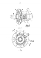
[008] A figura 1 é uma vista em perspectiva de uma montagem diferencial equipada com a montagem de retenção da presente invenção.[008] Figure 1 is a perspective view of a differential assembly equipped with the retaining assembly of the present invention.
[009] A figura 2 é uma vista terminal da montagem diferencial mostrada na figura 1.[009] Figure 2 is an end view of the differential assembly shown in figure 1.
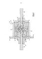
[010] A figura 3 é uma vista seccional tomadageralmente ao longo da linha 3-3 da figura 2.[010] Figure 3 is a sectional view taken generally along line 3-3 of figure 2.
[011] A figura 4 é uma vista seccional tomadageralmente ao longo da linha 4-4 da figura 2.[011] Figure 4 is a sectional view taken generally along line 4-4 of figure 2.
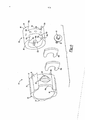
[012] A figura 5 é uma vista em perspectivaexplodida da montagem de retenção da presente invenção.[012] Figure 5 is an exploded perspective view of the retaining assembly of the present invention.
[013] A figura 6 é uma vista em perspectiva damontagem de retenção em um primeiro estágio de montagem.[013] Figure 6 is a perspective view of the retaining assembly in a first stage of assembly.
[014] A figura 7 é uma vista em perspectiva damontagem de retenção em um segundo estágio de montagem.[014] Figure 7 is a perspective view of the retention assembly in a second stage of assembly.
[015] A figura 8 é uma vista em perspectiva damontagem de retenção em um estágio de montagem final.[015] Figure 8 is a perspective view of the retaining assembly in a final assembly stage.
[016] Com referência às figuras 1 a 8, um mecanismo de retenção de eixo para uso com uma montagem diferencial 10 será descrito. A montagem diferencial 10 será descrita em detalhes suficientes para descrever a estrutura e a função do mecanismo de retenção de eixo. Em particular, a montagem diferencial 10 é o tipo de eixo paralelo helicoidal usado em aplicações de linha de acionamento de veículo automotor. No entanto, deve ser entendido que o mecanismo de retenção de eixo da presente invenção é aplicável para uso com muitas variantes da montagem diferencial 10 e, como tal, a estrutura particular mostrada é pretendida meramente para ser exemplificativa em natureza.[016] With reference to figures 1 to 8, an axle retaining mechanism for use with a
[017] A montagem diferencial 10 inclui uma montagem de alojamento 12, que define uma câmara interna 14. A montagem de alojamento 12 inclui um tambor' principal 16 e tampa terminal 18 que é presa a um flange radial 20 do tambor 16 por uma pluralidade de parafusos (não mostrados) instalados através dos furos de sobreposição alinhados 22. Como é conhecido, um anel ou engrenagem de oblíqua pode ser fixada 'ao flange radial 20 na montagem de alojamento 12 para transferir energia rotacional (isto e, torque de acionamento) do mesmo. A montagem de alojamento 12 define um par de aberturas alinhadas axialmente 24 e 26 em comunicação com a câmara 14 e que é adaptado para receber e suportar, de forma rotacionável, os segmentos terminais de um par de eixos de saída, aqui a seguir referido como eixos 28a e 28b. O segmento terminal dos eixos 28a e 28b inclui uma ranhura anular em recesso correspondente 30a e 30b, que separa uma almofada terminal semelhante a botão 32a, 32b de um segmento externamente ranhurado 34a, 34b. As almofadas terminais 32a, 32b têm uma superfície periférica circular correspondente 36a, 36b, uma superfície de face externa 38a, 38b e a superfície de face interna 40a, 40b. O diâmetro externo das almofadas terminais 32a, 32b é mostrado para ser ligeiramente menor que o diâmetro externo do segmento ranhurado 34a, 34b nos eixos 29a, 28b. Como será detalhado, uma montagem de retenção 42 é instalada entre as almofadas terminais 32a,32b para manter o espaçamento axial entre os eixos 28a e 28b e impedem separação axial dos mesmos.[017] The
[018] A montagem diferencial 10 inclui um conjunto de engrenagem planetária, que é operável para transferir torque de acionamento da montagem de alojamento 12 para os eixos 28a, 28b em uma maneira que facilita a diferenciação de velocidade entre os mesmos. O conjunto de engrenagem é montado na câmara 14 e inclui um par de engrenagens laterais 44a, 44b que tem ranhuras internas 46a, 46b enredadas com segmentos externamente ranhurados 34a, 34b em um correspondente dos eixos 28a, 28b. Além disso, as engrenagens laterais 44a, 44b incluem eixos axiais 45a, 45b, que são retidos em encaixes anulares correspondentes 47a, 47b formados no tambor 46 e tampa terminal 18 da montagem de alojamento 12. Os retentores dimensionados do tipo C, ou clipes do tipo C 48a, 48b são retidos em ranhuras alinhadas 30a, 30b para impedir que o eixo mova-se para fora.[018]
[019] O conjunto de engrenagem helicoidal também inclui uma série de primeiros pinhões 50 suportados, na forma de mancal, nas cavidades 52 formadas nos segmentos de eixo aumentados 54 do tambor 16, e uma série de segundo pinhões 56 suportados, na forma de mancal, em cavidades 58 também formados em segmentos de eixo 54 do tambor 16. As cavidades 52 e 58 são formadas em conjuntos pareados tal que eles comunicam-se um com o outro e com a câmara 14. Além disso, as cavidades 52 e 58 são alinhadas para serem substancialmente paralelas ao eixo de rotação dos eixos 28a, 28b. Quando montados, os primeiros pinhões 50 enredamse com as engrenagens laterais 44a, enquanto os segundos pinhões 56 enredam-se com a engrenagem lateral 44b. Além disso, os conjuntos pareados são dispostos tal que um dos primeiros pinhões 50 também enreda com um dos segundos pinhões 56. As janelas 60 são formadas no tambor 16 entre os segmentos de eixo 54 e são proporcionados para permitir acesso ao conjunto de engrenagens dentro da câmara 14.[019] The helical gear set also includes a series of first supported
[020] De acordo com a presente invenção, a montagem de retenção 42 é fornecida para manter engrenagens laterais 44a, 44b e eixos 28a, 28b em relação axialmente espaçada um em relação ao outro, enquanto permite impedir liberação não intencional dos clipes tipo C 48a, 48b das ranhuras 30a, 30b. A montagem de retenção 42 inclui um anel 62, um espaçador 64, clipes tipo C 48a, 48b e um prendedor 66. Como será melhor visualizado na figura 5, o anel 62 é de formato substancialmente cilíndrico tendo uma superfície cilíndrica interna 68 e uma superfície cilíndrica externa 70 que se estende de uma primeira face terminal 72 para uma segunda face terminal 74. A superfície cilíndrica externa 70 é interrompida por uma pluralidade de semicírculos. Os semicírculos 76 funcionam para impedir que o anel 62 rode dentro da montagem de eixo 12. Uma fenda elongada 78 estende- se radialmente através do anel 62 a fim de fornecer uma abertura de acesso para os prendedores 6, como será descrito em maiores detalhes aqui a seguir. Um contrafuro 80 é formado em uma porção da superfície cilíndrica externa 70 em comunicação com a fenda elongada 78 para fornecer um assento para uma arruela 82 usada em conjunto com o prendedor 66. Um par de janelas 84a e 84b é formado dentro do anel 62 para proporcionar acesso aos clipes tipo C 48a e 48b. A janela84a estende-se da superfície cilíndrica interna 68 para a superfície cilíndrica 48a. A janela 84b é similarmente dimensionada, formatada e posicionada como uma característica removida da segunda face terminal 74.[020] According to the present invention, the
[021] O espaçador 64 é um membro substancialmente cilíndrico que tem uma superfície externa 86 que se estende a partir de uma primeira face terminal 88 para uma segunda face terminal 90. O espaçador 64 inclui primeiro e segundo recessos 92a e 92b dimensionados e formatados para recebimento dos segmentos terminais dos eixos 28a, 28b, bem como clipes tipo C 48a, 48b. O recesso 29a é substancialmente em formato “C”, tendo uma primeira região substancialmente planar 94a espaçada para longe de uma segunda região substancialmente planar 96a. Uma porção em formato de arco 98a interconecta a primeira região 94a e a segunda região 96a. O recesso 92b é similarmente dimensionado e formatado para incluir uma primeira região 94b e uma segunda região 96b interconectadas por uma porção em formato de arco 98b (não mostrada). Uma teia 100 separa o recesso 92a e o recesso 92b. A teia 100 inclui uma primeira superfície substancialmente planar 102 posicionada substancialmente paralela e a espaçada para longe de uma segunda superfície substancialmente planar 104. Uma pluralidade de aberturas 106 estende-se radialmente para dentro do espaçador 64 a partir da superfície exterior 86. As aberturas 106 são circunferencialmente espaçadas um do outro e posicionado ao longo de um plano intermediário entre a primeira face terminal 88 e a segunda face terminal 90. As aberturas 106 fornecem a um instalador de montagem de retenção 42 um método para rodar o espaçador 64, enquanto o espaçador 64 está posicionado dentro do anel 62. Um alfinete ou outro braço de alavanca (não mostrado) é inserido através da fenda elongada 78 do anel 62 e para dentro de aberturas 106 para aplicar um torque ao espaçador 64 e rodar o espaçador em relação ao anel 62. O espaçador 64 inclui uma abertura de rosca 108 que se estende para dentro a partir da superfície externa 86 ao longo de um eixo alinhado com os recessos 92a e 92b. A abertura rosqueada 108 entra a partir do lado do espaçador 64, onde as extremidades de abertura dos recessos 92a, 92b não estão presentes.[021]
[022] As figuras 6-8 mostram a ordem de operações feitas para reter os eixos 28a e 28b para a montagem diferencial 10 usando a montagem de retenção 42. Deve ser botado que o anel 62 e o espaçador 64 estão axialmente instalados dentro da câmara 14 durante uma fase de construção inicial da montagem diferencial 10. A montagem diferencial 10 é, então, sobreposta, de forma rotacionável, dentro de um transeixo ou portador de eixo traseiro. O anel 62 e espaçador 64 permanecem cativos dentro da câmara 14 e não são removidos da montagem diferencial, enquanto a montagem diferencial está cativa dentro de um alojamento de portador (não mostrado).[022] Figures 6-8 show the order of operations made to retain the
[023] Para reter os eixos 28a, 28b à montagem diferencial 10, cada eixo é inserido dentro de suas respectivas aberturas de montagem de alojamento 24, 206 e na câmara 14. Os eixos 28a e 28b são transladados até as superfícies de face externas 38a e 38b contatarem a primeira superfície 102 e a segunda superfície 104 da teia 100. Nesse momento, os recessos 92a e 92b do espaçador 94 devem estar alinhados com as janelas 84a e 84b do anel 62. Se essa condição não existe atualmente, o instalador insere uma vareta através da fenda elongada 78 em uma das aberturas 106 formadas dentro do espaçador 64 para rodar o espaçador 64 e alinhar os recessos 92a, 92b com as janelas 84a, 84b. Uma vez que os recessos e as janelas tenham sido alinhados, o clipe tipo C 48a é transladado através da janela 84a e o recesso 92a para dentro da ranhura 30a do eixo 28a. De forma similar, o clipe 48b é transladado através da janela 84b e para dentro do recesso 92b, enquanto entra na ranhura 30b do eixo 28b. Nesse momento, os eixos 28a e 28b são restringidos de movimento ao longo dos eixos rotacionais dos mesmos pela teia 100 e as faces terminais das engrenagens laterais 44a, 44b.[023] To retain
[024] Para manter a posição adequada dos clipes tipo C 48a e 48b, o espaçador 64 é girado aproximadamente 180 graus para capturar os clipes tipo C dentro do anel 62. Como anteriormente descrito, o espaçador 64 pode ser rotacionado em relação ao anel 62 através de isso de um alfinete e aberturas 106. Uma vez que o espaçador 64 é propriamente posicionado em relação ao anel 62, a abertura rosqueada 108 será alinhada com a fenda elongada 78 e contrafuro 80. Nesse momento, o usuário engata o prendedor 66, de forma rosqueada, com a abertura de rosca 108 para restringir o espaçador 64 de rodar em relação ao anel 62. O processo de montagem pode ser revertido para permitir remoção dos eixos 28a, 28b da montagem diferencial 10.[024] To maintain the proper position of type C clips 48a and 48b,
Claims (13)
Applications Claiming Priority (2)
| Application Number | Priority Date | Filing Date | Title |
|---|---|---|---|
| US11/116,068 US7232397B2 (en) | 2005-04-27 | 2005-04-27 | Axleshaft retention assembly for differentials and method of assembly |
| US11/116,068 | 2005-04-27 |
Publications (3)
| Publication Number | Publication Date |
|---|---|
| BRPI0601560A BRPI0601560A (en) | 2007-07-17 |
| BRPI0601560A8 BRPI0601560A8 (en) | 2020-11-03 |
| BRPI0601560B1 true BRPI0601560B1 (en) | 2020-12-08 |
Family
ID=36753926
Family Applications (1)
| Application Number | Title | Priority Date | Filing Date |
|---|---|---|---|
| BRPI0601560-3A BRPI0601560B1 (en) | 2005-04-27 | 2006-04-26 | shaft retaining assembly for differentials |
Country Status (4)
| Country | Link |
|---|---|
| US (1) | US7232397B2 (en) |
| EP (1) | EP1717485B1 (en) |
| KR (1) | KR101244988B1 (en) |
| BR (1) | BRPI0601560B1 (en) |
Families Citing this family (5)
| Publication number | Priority date | Publication date | Assignee | Title |
|---|---|---|---|---|
| DE102007004710B4 (en) * | 2007-01-31 | 2012-09-27 | Schaeffler Technologies Gmbh & Co. Kg | Spur gear |
| US9347542B2 (en) * | 2008-09-30 | 2016-05-24 | American Axle & Manufacturing, Inc. | Parallel-axis helical differential assembly |
| WO2011072004A2 (en) | 2009-12-08 | 2011-06-16 | American Axle & Manufacturing, Inc. | Disconnecting rear drive axle for longitudinally arranged powertrains |
| DE102013220393A1 (en) | 2013-10-10 | 2015-04-16 | Zf Friedrichshafen Ag | Securing means for securing an axial stop element on a shaft |
| US9423014B2 (en) * | 2014-10-09 | 2016-08-23 | American Axle & Manufacturing, Inc. | Differential assembly with C-lock keeper |
Family Cites Families (24)
| Publication number | Priority date | Publication date | Assignee | Title |
|---|---|---|---|---|
| US3402801A (en) * | 1965-07-29 | 1968-09-24 | Borg Warner | Differential mechanism |
| US3400611A (en) * | 1966-05-06 | 1968-09-10 | Borg Warner | Differential mechanism |
| US3624717A (en) * | 1970-02-06 | 1971-11-30 | Eaton Yale & Towne | Axle shaft retention system |
| US3864992A (en) * | 1973-05-31 | 1975-02-11 | Gen Motors Corp | Limited slip differential having shaft locking and clutch actuating means |
| US4365524A (en) * | 1980-09-05 | 1982-12-28 | Tractech, Inc. | Torque-proportioning differential with wedge block thrust bearing means |
| US4512211A (en) * | 1983-03-15 | 1985-04-23 | The Gleason Works | Differential assembly having means for locking and positioning axle shafts therein |
| US4495835A (en) * | 1983-03-15 | 1985-01-29 | The Gleason Works | Differential gearing assembly |
| US4512221A (en) * | 1983-08-25 | 1985-04-23 | Picone John A | Electric powered adjustable wrench |
| US4751853A (en) * | 1985-01-09 | 1988-06-21 | Tractech, Inc. | Differential with equal depth pinion cavities |
| US5131894A (en) * | 1991-02-27 | 1992-07-21 | Dana Corporation | Axle shaft retainer of use in differential case |
| US5221238A (en) * | 1992-08-21 | 1993-06-22 | Dyneet Corporation | Differential with preload means and sectional spacer means |
| US5554081A (en) * | 1995-03-08 | 1996-09-10 | Zexel Torsen Inc. | Differential with distributed planet gears |
| US5733216A (en) * | 1995-03-08 | 1998-03-31 | Zexel Torsen Inc. | Thrust-block for C-clip differential |
| US5671640A (en) * | 1996-04-30 | 1997-09-30 | Tractech Inc. | Locking differential with pre-load means and C-clip retainers |
| US5938558A (en) * | 1997-09-19 | 1999-08-17 | Eaton Corporation | Limited slip differential and improved differential housing assembly therefor |
| JP3091173B2 (en) * | 1997-10-22 | 2000-09-25 | ローム株式会社 | Digital / analog converter |
| US5957801A (en) * | 1998-05-11 | 1999-09-28 | Zexel Torsen Inc. | Coil spring preload for parallel-axis differential |
| US5983754A (en) * | 1998-05-13 | 1999-11-16 | Vehicular Technologies, Inc. | Split spacer for a differential assembly |
| US5984823A (en) * | 1998-08-27 | 1999-11-16 | American Axle & Manufacturing, Inc. | Differential with shaft locking mechanism |
| US6053838A (en) * | 1999-05-13 | 2000-04-25 | American Axle & Manufacturing, Inc. | Helical differential assembly |
| US6047615A (en) * | 1999-05-14 | 2000-04-11 | Vehicular Technologies, Inc. | Positive acting differential with slotted solid spacer and axle thrust slug |
| US6325737B1 (en) * | 2000-03-22 | 2001-12-04 | American Axle & Manufacturing, Inc. | Helical gear differential with geared lube pump |
| JP4029874B2 (en) * | 2003-09-29 | 2008-01-09 | 日産自動車株式会社 | Vehicle drive device |
| US7022041B2 (en) * | 2004-03-05 | 2006-04-04 | American Axle & Manufacturing, Inc. | Helical gear differential |
-
2005
- 2005-04-27 US US11/116,068 patent/US7232397B2/en active Active
-
2006
- 2006-04-21 KR KR1020060036138A patent/KR101244988B1/en active IP Right Grant
- 2006-04-21 EP EP06008312A patent/EP1717485B1/en active Active
- 2006-04-26 BR BRPI0601560-3A patent/BRPI0601560B1/en active IP Right Grant
Also Published As
| Publication number | Publication date |
|---|---|
| BRPI0601560A (en) | 2007-07-17 |
| KR101244988B1 (en) | 2013-03-25 |
| EP1717485A2 (en) | 2006-11-02 |
| US20060247088A1 (en) | 2006-11-02 |
| EP1717485A3 (en) | 2008-05-28 |
| BRPI0601560A8 (en) | 2020-11-03 |
| KR20060113420A (en) | 2006-11-02 |
| EP1717485B1 (en) | 2011-06-15 |
| US7232397B2 (en) | 2007-06-19 |
Similar Documents
| Publication | Publication Date | Title |
|---|---|---|
| US7951037B2 (en) | Four pinion differential with cross pin retention unit and related method | |
| BRPI0601560B1 (en) | shaft retaining assembly for differentials | |
| JP4201448B2 (en) | Series of transmissions that employ an internally meshing planetary gear structure | |
| BRPI0500676B1 (en) | differential assembly for a vehicle and method for mounting a first and second side gear within a differential housing | |
| US5984823A (en) | Differential with shaft locking mechanism | |
| CA1313593C (en) | Planetary carrier assembly and method | |
| EP1052430A2 (en) | Differential casing | |
| JPH0942419A (en) | Automatic locking type differential gear | |
| JP2008082533A (en) | Vehicular differential gear and its assembling method | |
| JPH0135965Y2 (en) | ||
| JPH0135967Y2 (en) | ||
| ES2235773T3 (en) | DIFFERENTIAL CONSTITUTED BY A COMBINATION OF PARALLEL AXIS GEARS WITH BRAKE BITS MOUNTED ON THE GEARS. | |
| JP2003083422A (en) | Planetary gear device | |
| JP4688909B2 (en) | Series of transmissions that employ an internally meshing planetary gear structure | |
| JP2008051305A (en) | Vehicular differential case and vehicular differential device equipped therewith | |
| JP2000065186A (en) | Differential for vehicle | |
| JPH0752997Y2 (en) | Lubrication structure of planetary gear unit | |
| JP2008082544A (en) | Vehicular differential gear | |
| JP3565279B2 (en) | Inner mesh planetary gear structure | |
| JPH09317851A (en) | Differential gear | |
| JP4784443B2 (en) | Vehicle differential | |
| US8585535B2 (en) | High torque capacity three output differential | |
| US9121429B2 (en) | Threaded fastener positive anti-rotation locking device | |
| KR200238171Y1 (en) | Gear installed bearing | |
| JPH0522928U (en) | Planetary gear mechanism |
Legal Events
| Date | Code | Title | Description |
|---|---|---|---|
| B06F | Objections, documents and/or translations needed after an examination request according [chapter 6.6 patent gazette] | ||
| B06U | Preliminary requirement: requests with searches performed by other patent offices: procedure suspended [chapter 6.21 patent gazette] | ||
| B09A | Decision: intention to grant [chapter 9.1 patent gazette] | ||
| B03H | Publication of an application: rectification [chapter 3.8 patent gazette] |
Free format text: REFERENTE A RPI 1906 DE 17/07/2007, QUANTO AO INID (71) |
|
| B16A | Patent or certificate of addition of invention granted |
Free format text: PRAZO DE VALIDADE: 10 (DEZ) ANOS CONTADOS A PARTIR DE 08/12/2020, OBSERVADAS AS CONDICOES LEGAIS. |