BR112018011850B1 - METHOD AND APPLIANCE TO CHECK A TIRE - Google Patents
METHOD AND APPLIANCE TO CHECK A TIRE Download PDFInfo
- Publication number
- BR112018011850B1 BR112018011850B1 BR112018011850-8A BR112018011850A BR112018011850B1 BR 112018011850 B1 BR112018011850 B1 BR 112018011850B1 BR 112018011850 A BR112018011850 A BR 112018011850A BR 112018011850 B1 BR112018011850 B1 BR 112018011850B1
- Authority
- BR
- Brazil
- Prior art keywords
- tire
- light source
- image
- light
- way
- Prior art date
Links
- 238000000034 method Methods 0.000 title claims abstract description 32
- 230000005855 radiation Effects 0.000 claims abstract description 104
- 230000007547 defect Effects 0.000 claims description 54
- 238000012545 processing Methods 0.000 claims description 31
- 230000003287 optical effect Effects 0.000 claims description 27
- 238000009304 pastoral farming Methods 0.000 claims description 22
- 238000005286 illumination Methods 0.000 claims description 20
- 230000008569 process Effects 0.000 claims description 6
- 230000003213 activating effect Effects 0.000 claims 2
- 238000001514 detection method Methods 0.000 description 17
- 230000006835 compression Effects 0.000 description 15
- 238000007906 compression Methods 0.000 description 15
- 239000011324 bead Substances 0.000 description 13
- 238000004519 manufacturing process Methods 0.000 description 10
- 238000004458 analytical method Methods 0.000 description 7
- 239000003086 colorant Substances 0.000 description 6
- 150000001875 compounds Chemical class 0.000 description 6
- 238000012795 verification Methods 0.000 description 6
- 230000036961 partial effect Effects 0.000 description 5
- 239000011159 matrix material Substances 0.000 description 4
- 230000008878 coupling Effects 0.000 description 3
- 238000010168 coupling process Methods 0.000 description 3
- 238000005859 coupling reaction Methods 0.000 description 3
- 238000007689 inspection Methods 0.000 description 3
- 238000003908 quality control method Methods 0.000 description 3
- 230000004913 activation Effects 0.000 description 2
- 239000013536 elastomeric material Substances 0.000 description 2
- 230000017525 heat dissipation Effects 0.000 description 2
- 230000000670 limiting effect Effects 0.000 description 2
- 230000002829 reductive effect Effects 0.000 description 2
- 238000012800 visualization Methods 0.000 description 2
- 230000001944 accentuation Effects 0.000 description 1
- XAGFODPZIPBFFR-UHFFFAOYSA-N aluminium Chemical compound [Al] XAGFODPZIPBFFR-UHFFFAOYSA-N 0.000 description 1
- 229910052782 aluminium Inorganic materials 0.000 description 1
- 238000003491 array Methods 0.000 description 1
- 125000000484 butyl group Chemical group [H]C([*])([H])C([H])([H])C([H])([H])C([H])([H])[H] 0.000 description 1
- 230000008859 change Effects 0.000 description 1
- 239000011248 coating agent Substances 0.000 description 1
- 238000000576 coating method Methods 0.000 description 1
- 238000010276 construction Methods 0.000 description 1
- 230000007812 deficiency Effects 0.000 description 1
- 230000002950 deficient Effects 0.000 description 1
- 238000013461 design Methods 0.000 description 1
- 238000009826 distribution Methods 0.000 description 1
- 230000000694 effects Effects 0.000 description 1
- 230000005670 electromagnetic radiation Effects 0.000 description 1
- 239000000284 extract Substances 0.000 description 1
- 238000001914 filtration Methods 0.000 description 1
- 239000011521 glass Substances 0.000 description 1
- 238000009499 grossing Methods 0.000 description 1
- 238000005304 joining Methods 0.000 description 1
- 239000000463 material Substances 0.000 description 1
- 238000005259 measurement Methods 0.000 description 1
- 230000006740 morphological transformation Effects 0.000 description 1
- 238000000465 moulding Methods 0.000 description 1
- 238000003825 pressing Methods 0.000 description 1
- 230000001681 protective effect Effects 0.000 description 1
- 230000003014 reinforcing effect Effects 0.000 description 1
- 230000000284 resting effect Effects 0.000 description 1
- 230000035945 sensitivity Effects 0.000 description 1
- 239000007787 solid Substances 0.000 description 1
- 238000001228 spectrum Methods 0.000 description 1
- 230000002123 temporal effect Effects 0.000 description 1
- 238000013519 translation Methods 0.000 description 1
- 238000004148 unit process Methods 0.000 description 1
- 230000000007 visual effect Effects 0.000 description 1
- 238000004073 vulcanization Methods 0.000 description 1
Images


Classifications
-
- G—PHYSICS
- G01—MEASURING; TESTING
- G01M—TESTING STATIC OR DYNAMIC BALANCE OF MACHINES OR STRUCTURES; TESTING OF STRUCTURES OR APPARATUS, NOT OTHERWISE PROVIDED FOR
- G01M17/00—Testing of vehicles
- G01M17/007—Wheeled or endless-tracked vehicles
- G01M17/02—Tyres
- G01M17/027—Tyres using light, e.g. infrared, ultraviolet or holographic techniques
-
- G—PHYSICS
- G01—MEASURING; TESTING
- G01M—TESTING STATIC OR DYNAMIC BALANCE OF MACHINES OR STRUCTURES; TESTING OF STRUCTURES OR APPARATUS, NOT OTHERWISE PROVIDED FOR
- G01M17/00—Testing of vehicles
- G01M17/007—Wheeled or endless-tracked vehicles
- G01M17/02—Tyres
-
- G—PHYSICS
- G01—MEASURING; TESTING
- G01N—INVESTIGATING OR ANALYSING MATERIALS BY DETERMINING THEIR CHEMICAL OR PHYSICAL PROPERTIES
- G01N21/00—Investigating or analysing materials by the use of optical means, i.e. using sub-millimetre waves, infrared, visible or ultraviolet light
- G01N21/84—Systems specially adapted for particular applications
- G01N21/88—Investigating the presence of flaws or contamination
- G01N21/8806—Specially adapted optical and illumination features
-
- G—PHYSICS
- G01—MEASURING; TESTING
- G01N—INVESTIGATING OR ANALYSING MATERIALS BY DETERMINING THEIR CHEMICAL OR PHYSICAL PROPERTIES
- G01N21/00—Investigating or analysing materials by the use of optical means, i.e. using sub-millimetre waves, infrared, visible or ultraviolet light
- G01N21/84—Systems specially adapted for particular applications
- G01N21/88—Investigating the presence of flaws or contamination
- G01N21/8851—Scan or image signal processing specially adapted therefor, e.g. for scan signal adjustment, for detecting different kinds of defects, for compensating for structures, markings, edges
-
- G—PHYSICS
- G01—MEASURING; TESTING
- G01N—INVESTIGATING OR ANALYSING MATERIALS BY DETERMINING THEIR CHEMICAL OR PHYSICAL PROPERTIES
- G01N21/00—Investigating or analysing materials by the use of optical means, i.e. using sub-millimetre waves, infrared, visible or ultraviolet light
- G01N21/84—Systems specially adapted for particular applications
- G01N21/88—Investigating the presence of flaws or contamination
- G01N21/95—Investigating the presence of flaws or contamination characterised by the material or shape of the object to be examined
-
- G—PHYSICS
- G01—MEASURING; TESTING
- G01N—INVESTIGATING OR ANALYSING MATERIALS BY DETERMINING THEIR CHEMICAL OR PHYSICAL PROPERTIES
- G01N21/00—Investigating or analysing materials by the use of optical means, i.e. using sub-millimetre waves, infrared, visible or ultraviolet light
- G01N21/84—Systems specially adapted for particular applications
- G01N21/88—Investigating the presence of flaws or contamination
- G01N21/8806—Specially adapted optical and illumination features
- G01N2021/8812—Diffuse illumination, e.g. "sky"
-
- H—ELECTRICITY
- H04—ELECTRIC COMMUNICATION TECHNIQUE
- H04N—PICTORIAL COMMUNICATION, e.g. TELEVISION
- H04N23/00—Cameras or camera modules comprising electronic image sensors; Control thereof
- H04N23/56—Cameras or camera modules comprising electronic image sensors; Control thereof provided with illuminating means
Abstract
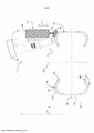
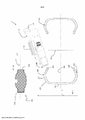
MÉTODO E APARELHO PARA VERIFICAR UM PNEU A invenção se refere a um método para verificar um pneu, compreendendo: - prover um pneu (200) a ser verificado; - associar uma primeira fonte de luz (110) e uma segunda fonte de luz (108) capazes de ser independentemente ativadas com uma câmera (105); - aplicar uma primeira força contra uma primeira porção da superfície (202) do dito pneu de maneira tal a gerar uma primeira porção de superfície deformada; - iluminar a dita primeira porção da superfície deformada do dito pneu com uma primeira radiação de luz emitida pela dita primeira fonte de luz (110); - manter a dita segunda fonte de luz (108) inativa durante a dita deformação; - adquirir uma primeira imagem da dita primeira porção da superfície deformada iluminada pela dita primeira radiação de luz por meio da dita câmera (105); - remover a dita primeira força da dita primeira porção da superfície do dito pneu; - selecionar uma segunda porção da superfície pelo menos parcialmente diferente da dita primeira porção da superfície do dito pneu; - iluminar a dita segunda porção da superfície não deformada do dito pneu com uma segunda radiação de luz emitida pela dita segunda fonte de luz (108); - adquirir uma segunda imagem da dita segunda porção da superfície não deformada e iluminada (...).METHOD AND APPARATUS FOR CHECKING A TIRE The invention relates to a method for checking a tire, comprising: - providing a tire (200) to be checked; - associating a first light source (110) and a second light source (108) capable of being independently activated with a camera (105); - applying a first force against a first portion of the surface (202) of said tire in such a way as to generate a first portion of deformed surface; - illuminating said first portion of the deformed surface of said tire with a first light radiation emitted by said first light source (110); - keeping said second light source (108) inactive during said deformation; - acquiring a first image of said first portion of the deformed surface illuminated by said first light radiation by means of said camera (105); - removing said first force from said first surface portion of said tire; - selecting a second surface portion at least partially different from said first surface portion of said tire; - illuminating said second portion of the undeformed surface of said tire with a second light radiation emitted by said second light source (108); - acquiring a second image of said second portion of the undeformed and illuminated surface (...).
Description
[001] A presente invenção se refere a um método e um aparelho para verificar pneus, por exemplo, em uma linha de produção de pneu, em particular um método e aparelho para verificar a possível presença de defeitos na superfície, ou próxima a ela, de um pneu, mais em particular na superfície interna e/ou externa, ou próxima a ela, das paredes laterais de um pneu.[001] The present invention relates to a method and apparatus for checking tires, for example, on a tire production line, in particular a method and apparatus for checking the possible presence of defects on or near the surface, of a tyre, more in particular on, or close to, the inner and/or outer surface of the sidewalls of a tyre.
[002] Tipicamente, um pneu tem uma estrutura substancialmente toroidal em torno de um eixo geométrico de rotação do mesmo durante operação, e tem um plano intermediário axial perpendicular ao eixo geométrico de rotação, o dito plano tipicamente sendo um plano de simetria geométrica substancial, ignorando possíveis assimetrias menores, tal como padrão de rodagem e/ou a estrutura interna.[002] Typically, a tire has a substantially toroidal structure around an axis of rotation thereof during operation, and has an intermediate axial plane perpendicular to the axis of rotation, said plane typically being a plane of substantial geometric symmetry, ignoring possible minor asymmetries, such as the tread pattern and/or the internal structure.
[003] Duas porções do pneu são identificadas aqui: a coroa e as paredes laterais. A coroa compreende a banda de rodagem, o cinto e a porção correspondente da estrutura da carcaça radialmente interna a ela.[003] Two parts of the tire are identified here: the crown and the sidewalls. The crown comprises the tread, the belt and the corresponding portion of the carcass structure radially internal thereto.
[004] O termo “parede lateral” deve indicar uma das duas porções do pneu viradas uma para a outra e que se estende radialmente nos lados opostos da coroa até os talões, isto é, até os dois rebordos de extremidade radialmente internos do pneu, tendo extensão circular substancialmente perpendicular ao eixo geométrico de rotação; os ditos talões sendo destinados a cada par com um respectivo aro de montagem. Cada parede lateral, assim, compreende uma porção correspondente da estrutura da carcaça e, em uma posição axialmente externa dela, uma porção feita de material elastomérico adequado, geralmente chamado ‘parede lateral’.[004] The term "sidewall" shall indicate one of the two portions of the tire facing each other and extending radially on opposite sides of the crown to the beads, that is, to the two radially inner end edges of the tire, having a circular extension substantially perpendicular to the axis of rotation; said lugs being assigned to each pair with a respective mounting ring. Each sidewall thus comprises a corresponding portion of the carcass structure and, at an axially external position thereof, a portion made of suitable elastomeric material, generally called a 'sidewall'.
[005] Tipicamente, a estrutura da carcaça compreende pelo menos uma lona da carcaça tendo rebordos de extremidade respectivamente opostas envolvidas com respectivas estruturas de reforço circulares, geralmente chamadas “fios do talão”, integradas nas áreas identificadas anteriormente com os talões do nome. Em pneus “sem câmara de ar”, a lona da carcaça é completamente revestida com uma camada de material elastomérico preferivelmente a base de butila, normalmente chamada “revestimento” tendo excelentes características de impermeabilidade ao ar e se estendendo de um talão para o outro.[005] Typically, the carcass structure comprises at least one carcass ply having respectively opposite end edges wrapped with respective circular reinforcing structures, generally called "bead threads", integrated in the areas previously identified with the name beads. In “tubeless” tires, the carcass ply is completely coated with a layer of elastomeric material preferably based on butyl, commonly called “coating” having excellent air tightness characteristics and extending from one bead to the other.
[006] A estrutura de uma parede lateral também deve completamente incluir o então chamado “ombro”, isto é, a porção do pneu para união entre a coroa e a porção radialmente interna da parede lateral (em outras palavras, os dois ombros correspondem as duas ‘rebordos” circulares radial e axialmente externas do pneu). O ombro tem extensão circular substancialmente perpendicular ao eixo geométrico de rotação.[006] The structure of a sidewall must also completely include the so-called “shoulder”, that is, the portion of the tire for joining between the crown and the radially inner portion of the sidewall (in other words, the two shoulders correspond to the two radially and axially external circular 'beads' of the tyre). The shoulder has a circular extension substantially perpendicular to the axis of rotation.
[007] O termo “pneu” deve indicar o pneu acabado, isto é, depois das etapas de moldagem e vulcanização seguindo a etapa de construção.[007] The term “tyre” shall indicate the finished tire, that is, after the molding and vulcanization stages following the construction stage.
[008] O termo componente do pneu deve indicar qualquer elemento que desempenha uma função, ou uma porção do mesmo.[008] The term tire component shall indicate any element that performs a function, or a portion thereof.
[009] Os termos superfície externa ou interna do pneu respectivamente devem indicar a superfície que permanece visível depois do acoplamento do pneu com seu aro de montagem e que não é mais visível depois do dito acoplamento.[009] The terms external or internal surface of the tire respectively shall indicate the surface that remains visible after coupling the tire with its mounting rim and which is no longer visible after said coupling.
[0010] Os termos “óptico”, “luminoso” e similares se referem a uma radiação eletromagnética usada que tem pelo menos uma porção do espectro caindo em uma faixa ampliada da banda óptica, e não necessariamente caindo estritamente na banda óptica (em outras palavras 400 a 700 nm), por exemplo, uma faixa ampliada como esta da banda óptica pode se estender de ultravioleta a infravermelho (por exemplo, comprimentos de onda compreendidos entre cerca de 100 nm e cerca de 1 μm).[0010] The terms "optical", "luminous" and the like refer to an electromagnetic radiation used that has at least a portion of the spectrum falling in an extended range of the optical band, and not necessarily falling strictly in the optical band (in other words 400 to 700 nm), for example, such an extended range of the optical band can extend from ultraviolet to infrared (e.g., wavelengths between about 100 nm and about 1 µm).
[0011] No presente pedido de patente, um modelo de raio de radiação de luz é adotado, isto é, presume-se que radiação de luz incidente em um ponto de uma superfície e gerada por uma fonte não apontada (em cujo caso haveria um único raio) corresponde a um conjunto de raios luminosos incidentes no ponto e tendo direção de propagação retilínea que3 conecta cada ponto da fonte com o dito ponto da superfície, onde cada de tais raios tem uma fração assoviada da potência luminosa total incidente no ponto. Os termos “luz” e “radiação de luz”, a menos que de outra forma especificado, são usados indiferentemente.[0011] In the present patent application, a light radiation ray model is adopted, that is, it is assumed that light radiation incident on a point of a surface and generated by a non-pointed source (in which case there would be a single ray) corresponds to a set of luminous rays incident on the point and having a rectilinear direction of propagation that3 connects each point of the source with said point on the surface, where each of such rays has a whistled fraction of the total luminous power incident on the point. The terms "light" and "light radiation", unless otherwise specified, are used interchangeably.
[0012] O termo “radiação de luz direcional” incidente em um ponto de uma superfície deve indicar radiação de luz para a qual há um ângulo sólido tendo o ponto como vértice e amplitude menor ou igual a π/8 esterradianos na qual pelo menos 75% da potência luminosa total, preferivelmente pelo menos 90%, mais preferivelmente toda a potência luminosa cai.[0012] The term “directional light radiation” incident on a point of a surface shall indicate light radiation for which there is a solid angle having the point as vertex and amplitude less than or equal to π/8 steradians in which at least 75 % of total luminous power, preferably at least 90%, more preferably all luminous power falls.
[0013] O termo “radiação de luz difusa” deve indicar uma radiação de luz não direcional.[0013] The term “diffuse light radiation” shall indicate non-directional light radiation.
[0014] O termo “radiação de luz rasante” incidente em um ponto de uma superfície deve indicar uma radiação de luz na qual pelo menos 75% da potência luminosa total do mesmo incidente no ponto da superfície forma um ângulo de incidência menor ou igual a 60° com um plano tangente à superfície em cada dito ponto.[0014] The term “grazing light radiation” incident on a point on a surface shall indicate light radiation in which at least 75% of the total luminous power of the same incident on the surface point forms an angle of incidence less than or equal to 60° with a plane tangent to the surface at each said point.
[0015] O termo “imagem” ou sinônimo “imagem digital” deve indicar, no geral, uma base de dados, tipicamente contida em um arquivo de computador, na qual cada coordenada (tipicamente bidimensional) de um conjunto finito (tipicamente bidimensional e do tipo de matriz, isto é, N linhas x M colunas) das coordenadas espaciais (cada tipicamente correspondendo a um pixel) é associada com um conjunto correspondente de valores numéricos (que podem ser representativos das magnitudes de um tipo diferente). Por exemplo, em imagens monocromáticas (como aquelas na ‘escala de cinza’), tal como conjunto de valores coincide com um único valor em uma escala finita (tipicamente com 256 níveis ou tons), um valor como este, por exemplo, sendo representativo do nível de luminosidade (ou intensidade) da respectiva coordenada espacial quando visualizado, enquanto que em imagens coloridas o conjunto de valores representa o nível de luminosidade de múltiplas cores, ou canais, tipicamente as cores primárias (por exemplo, vermelho, verde e azul no modelo de cor RGB, enquanto que ciano, magenta, amarelo e preto no modelo colorido CMYK). O termo ‘imagem’ não necessariamente significa a visualização real da mesma.[0015] The term “image” or synonym “digital image” should indicate, in general, a database, typically contained in a computer file, in which each coordinate (typically two-dimensional) of a finite set (typically two-dimensional and the matrix type, i.e. N rows x M columns) of spatial coordinates (each typically corresponding to a pixel) is associated with a corresponding set of numerical values (which may be representative of magnitudes of a different type). For example, in monochrome images (such as those in 'greyscale'), as a set of values coincides with a single value on a finite scale (typically 256 levels or tones), a value like this, for example, being representative of the brightness level (or intensity) of the respective spatial coordinate when viewed, whereas in color images the set of values represents the brightness level of multiple colors, or channels, typically the primary colors (e.g. red, green, and blue in the RGB color model, while cyan, magenta, yellow and black in the CMYK color model). The term 'image' does not necessarily mean the actual visualization of the same.
[0016] Toda referência a uma “imagem digital” específica (por exemplo, a uma imagem digital bidimensional inicialmente adquirida no pneu) mais geralmente cobre qualquer imagem digital que pode ser obtida por meio de uma ou mais operações de processamento digital da dita imagem digital específica (como, por exemplo, filtração, equalização, “limitação”, transformações morfológicas - “abertura”, etc., - cálculos de gradiente, “suavização”, etc.).[0016] Any reference to a specific “digital image” (for example, to a two-dimensional digital image initially acquired on the tire) more generally covers any digital image that can be obtained by means of one or more operations of digital processing of said digital image (such as filtering, equalizing, “limiting”, morphological transformations - “opening”, etc., - gradient calculations, “smoothing”, etc.).
[0017] O termo “porção de superfície linear” deve indicar uma superfície porção tendo uma dimensão muito maior que a outra dimensão perpendicular a ela, tipicamente maior em pelo menos duas ordens de magnitude. A menor dimensão da porção de superfície linear é tipicamente menor ou igual a 0,1 mm.[0017] The term "linear surface portion" shall indicate a surface portion having one dimension much greater than the other dimension perpendicular to it, typically greater by at least two orders of magnitude. The smallest dimension of the linear surface portion is typically less than or equal to 0.1 mm.
[0018] O termo “imagem linear” deve indicar uma imagem digital tendo um número muito maior de colunas de pixels que o número de linhas, tipicamente maior em pelo menos duas ordens de magnitude. Tipicamente, o número de linhas é entre 1 e 4 e o número de colunas é maior que 1.000. O termo “linhas” e “colunas” são usados convencional e indiferentemente.[0018] The term “linear image” shall indicate a digital image having a much greater number of columns of pixels than the number of rows, typically greater by at least two orders of magnitude. Typically, the number of rows is between 1 and 4 and the number of columns is greater than 1000. The term "rows" and "columns" are used conventionally and interchangeably.
[0019] O termo “tempo de ciclo” em uma linha de produção compreendendo pelo menos uma estação de trabalho, preferivelmente uma pluralidade de estações de trabalho, e inserida em uma fábrica para produzir pneus deve indicar, em condições normais de operação, o tempo de trânsito máximo para um pneu sendo fabricado passar através de uma estação de trabalho na qual pelo menos uma porção de um componente do pneu em si é construída. Por exemplo, o tempo de ciclo pode ser compreendido entre cerca de 20 e cerca de 120 segundos.[0019] The term “cycle time” in a production line comprising at least one workstation, preferably a plurality of workstations, and inserted in a factory to produce tires should indicate, under normal operating conditions, the time maximum transit time for a tire being manufactured to pass through a workstation at which at least a portion of a component of the tire itself is constructed. For example, the cycle time can be from about 20 to about 120 seconds.
[0020] Em processos para produzir e construir pneus para rodas de veículo há uma necessidade de realizar controles de qualidade nos produtos produzidos, com o propósito de evitar pneus que são defeituosos ou em qualquer caso fora das especificações do projeto de ser capaz de ser liberado no mercado, e/ou de progressivamente ajustar os aparelhos e maquinário usados, de maneira a melhorar e aperfeiçoar o desempenho das operações realizadas no processo de produção.[0020] In processes to produce and build tires for vehicle wheels there is a need to carry out quality controls on the products produced, with the purpose of preventing tires that are defective or in any case outside the design specifications from being able to be released on the market, and/or to progressively adjust the devices and machinery used, in order to improve and perfect the performance of the operations carried out in the production process.
[0021] Tais controles de qualidade incluem, por exemplo, aqueles realizados por operadores humanos que gastam um período de tempo predeterminado, por exemplo, compreendido entre 30 s e 60 s, realizando um exame visual e tátil do pneu; se, na luz de seu/sua experiência e sensibilidade, o operador suspeitar que o pneu não atende certos padrões de controle de qualidade, o pneu em si é submetido a verificações adicionais, por meio de uma verificação humana mais detalhada e/ou aparelhos adequados, de maneira a mais profundamente avaliar possíveis deficiências estrutural e/ou de qualidade.[0021] Such quality controls include, for example, those performed by human operators who spend a predetermined period of time, for example, between 30 s and 60 s, performing a visual and tactile examination of the tire; if, in light of his/her experience and sensitivity, the operator suspects that the tire does not meet certain quality control standards, the tire itself is subjected to further checks, through more detailed human verification and/or suitable apparatus , in order to more deeply evaluate possible structural and/or quality deficiencies.
[0022] WO 2015/004587 do mesmo Requerente mostra um método e aparelho relativo, para verificar pneus em uma linha de produção, compreendendo: prover um pneu a ser verificado; elasticamente deformar uma porção da parede lateral do pneu por meio de uma força de compressão em uma superfície de contato externa da porção da parede lateral, a força de compressão tendo uma direção axial e vai na direção do plano da linha média; iluminar uma superfície interna e/ou externa da porção da parede lateral e detectar uma imagem da superfície iluminada; gerar um sinal de controle representativo da imagem detectada; e analisar o sinal de controle de maneira a detectar a possível presença de defeitos na porção da parede lateral.[0022] WO 2015/004587 by the same Applicant shows a method and relative apparatus for checking tires on a production line, comprising: providing a tire to be checked; elastically deforming a portion of the sidewall of the tire by means of a compressive force on an external contact surface of the sidewall portion, the compressive force having an axial direction and going in the direction of the midline plane; illuminating an inner and/or outer surface of the sidewall portion and detecting an image of the illuminated surface; generating a control signal representative of the detected image; and analyzing the control signal in order to detect the possible presence of defects in the sidewall portion.
[0023] EP 2322899 descreve um método para detectar irregularidades ínfimas na superfície de um pneu mediante inspeção. Uma superfície na região da parede lateral de um pneu é iluminada por uma luz vermelha emitida por meios de iluminação primários arranjados na direção de 45 graus com relação à linha normal à superfície. Ao mesmo tempo, a superfície é iluminada por uma linha azul que vem de meios de iluminação secundários arranjados em uma direção de -45 graus com relação à linha normal. A superfície iluminada é capturada por uma câmera linear da direção da linha normal. A irregularidade da superfície formada na superfície do pneu é detectada com base nas formas de onda da distribuição de luminância.[0023] EP 2322899 describes a method for detecting minute irregularities on the surface of a tire upon inspection. A surface in the sidewall region of a tire is illuminated by a red light emitted by primary illuminators arranged in the direction of 45 degrees to the line normal to the surface. At the same time, the surface is illuminated by a blue line that comes from secondary illuminators arranged in a direction of -45 degrees to the normal line. The illuminated surface is captured by a linear camera from the direction of the normal line. The surface irregularity formed on the tire surface is detected based on the luminance distribution waveforms.
[0024] US 2011/018999 mostra um dispositivo para avaliar a aparência da superfície de um pneu compreendendo uma câmara de cor linear incluindo meios para separar o feixe de luz refletido pela superfície do dito pneu e que entra na câmera em pelo menos duas cores primárias (R, G, B) de certos comprimentos de onda, de maneira tal a direcionar o feixe de luz para o máximo de sensores capazes de obter uma imagem de base em escala de cinza para cada das cores primárias, inúmeros meios de iluminação se igualam ao número das cores primárias, os ditos meios de iluminação sendo orientados de maneira a iluminar a superfície a ser avaliada em diferentes ângulos, distinguido em que cada meio de iluminação emite uma luz colorida (R, G, B) diferente daquela emitida por outros meios de iluminação, cujo comprimento de onda substancialmente corresponde ao comprimento de onda de uma das cores primárias selecionadas pela câmera.[0024] US 2011/018999 shows a device for evaluating the surface appearance of a tire comprising a linear color chamber including means for separating the light beam reflected by the surface of said tire and entering the camera into at least two primary colors (R, G, B) of certain wavelengths, in such a way as to direct the light beam to the maximum number of sensors capable of obtaining a grayscale base image for each of the primary colors, numerous lighting means are equal to the number of primary colors, said lighting means being oriented so as to illuminate the surface to be evaluated at different angles, distinguished in that each lighting means emits a colored light (R, G, B) different from that emitted by other means of illumination, whose wavelength substantially corresponds to the wavelength of one of the primary colors selected by the camera.
[0025] No campo da verificação de pneus, o Requerente estabeleceu em si o problema de analisar a superfície, interna e/ou externa, do pneu, por meio de aquisição de imagem óptica, por exemplo, digital, do mesmo e seu subsequente processamento, por exemplo, de maneira a detectar a possível presença de defeitos visíveis na superfície, minimizando a verificação por operadores humanos. Os defeitos procurados podem, por exemplo, ser irregularidades na superfície de um pneu (composto não vulcanizado, alterações na forma, etc.), desnível estrutural, cortes, presença de corpos estranhos na superfície, etc.[0025] In the field of tire verification, the Applicant set itself the problem of analyzing the surface, internal and/or external, of the tire, through the acquisition of an optical image, for example, digital, of the same and its subsequent processing , for example, in order to detect the possible presence of visible defects on the surface, minimizing verification by human operators. The defects sought can, for example, be irregularities on the surface of a tire (non-vulcanized compound, changes in shape, etc.), structural unevenness, cuts, presence of foreign bodies on the surface, etc.
[0026] O Requerente observou que de maneira que a verificação seja capaz de ser usada “em linha” dentro de uma fábrica de produção de pneu, é necessário que a verificação em si seja realizada em períodos de tempo curtos e com baixos custos.[0026] The Applicant noted that in order for the verification to be able to be used “in-line” within a tire production plant, it is necessary that the verification itself be carried out in short periods of time and at low costs.
[0027] Desta forma, o método para verificar o pneu por meio da aquisição e análise de imagens do mesmo para salientar possíveis defeitos do mesmo preferivelmente leva um período de tempo que é mantido no período de “tempo de ciclo” limitado mencionado anteriormente e ao mesmo tempo garante uma verificação exata da presença de defeitos no pneu em si, a custo razoavelmente baixo.[0027] In this way, the method for checking the tire through the acquisition and analysis of images of the same to highlight possible defects of the same preferably takes a period of time that is maintained in the previously mentioned limited “cycle time” period and at the at the same time it guarantees an exact check for the presence of defects in the tire itself, at a reasonably low cost.
[0028] O Requerente observou que embora os documentos anteriores, em alguns casos, efetivamente descrevam dispositivos que podem ser úteis para detectar defeitos específicos em um pneu, de maneira a detectar uma pluralidade de defeitos um dispositivo diferente teria que ser usado para cada defeito específico tendo características específicas para identificar o defeito específico. O Requerente, de fato, observou adicionalmente por meio de uma análise dos dispositivos do tipo ilustrado em WO 2015/004587, EP 2322899 e US 2011/018999 que um tipo específico de iluminação acoplado com uma câmera ou sensor diferente é preferido para a detecção correta de um defeito específico ou de uma pluralidade (limitada) de defeitos específicos entre os vários defeitos que podem ocorrer em um pneu. O Requerente certamente entendeu que o uso do mesmo dispositivo com a mesma iluminação e câmera para a análise de todo o pneu levaria à falta de detecção, ou detecção muito difícil, por meio de processamento de imagem, de alguns defeitos e, em particular, de alguns defeitos bidimensionais, isto é, que não envolvem uma alteração da altura da superfície como, por exemplo, os cortes nos rebordos correspondentes.[0028] The Applicant noted that although the previous documents, in some cases, effectively describe devices that can be useful to detect specific defects in a tire, in order to detect a plurality of defects a different device would have to be used for each specific defect having specific characteristics to identify the specific defect. The Applicant has, in fact, further observed through an analysis of devices of the type illustrated in WO 2015/004587, EP 2322899 and US 2011/018999 that a specific type of lighting coupled with a different camera or sensor is preferred for correct detection of a specific defect or a (limited) plurality of specific defects among the various defects that can occur in a tyre. The Applicant certainly understood that the use of the same device with the same lighting and camera for the analysis of the entire tire would lead to the lack of detection, or very difficult detection, through image processing, of some defects and, in particular, of some two-dimensional defects, i.e. defects that do not involve a change in the height of the surface, such as, for example, cuts in the corresponding edges.
[0029] Entretanto, o fornecimento de um grande número de diferentes dispositivos cada com diferentes características para identificar diferentes defeitos aumenta a complexidade da linha de produção de pneu na fábrica dedicada a verificá-los e os custos do mesmo. Além do mais, o fornecimento de diferentes dispositivos exige movimento contínuo dos mesmos na direção do pneu quando na etapa de análise e longe dela quando um dispositivo diferente está na etapa de análise. Isto aumenta o tempo de ciclo, uma vez que o assim chamado “tempo ocioso” no qual a tradução dos dispositivos não usados acontece é substancial, mesmo se necessário evitar colisões ou interferência entre dispositivos diferentes.[0029] However, providing a large number of different devices each with different characteristics to identify different defects increases the complexity of the tire production line at the factory dedicated to checking them and the costs of the same. Furthermore, providing different devices requires continuous movement of them towards the tire when in the analysis step and away from it when a different device is in the analysis step. This increases cycle time, since the so-called “idle time” in which translation of unused devices takes place is substantial, even if necessary to avoid collisions or interference between different devices.
[0030] O Requerente, desta forma, estabeleceu em si o problema de elaborar um método e um aparelho para verificar pneus capazes de adquirir imagens da superfície de um pneu, em particular para detectar mais que um tipo de defeito na superfície do mesmo, que são adequados para a aplicação em linha dentro de uma linha de produção de pneu de uma fábrica de produção, em outras palavras, adequados para ser usados para obter tempos e custos de operação reduzidos, e capazes de prover resultados confiáveis.[0030] The Applicant thus set itself the problem of devising a method and an apparatus for checking tires capable of acquiring images of the surface of a tire, in particular to detect more than one type of defect on the surface thereof, which are suitable for in-line application within a tire production line of a production plant, in other words, suitable to be used to achieve reduced operating times and costs, and capable of providing reliable results.
[0031] O Requerente tem percebeu que ter um sistema de detecção com pelo menos duas fontes de luz torna possível variar a iluminação de uma porção da superfície do pneu de acordo com o tipo de defeito desejado para ser identificado e adaptar a aquisição de imagens tanto na luz difundida quanto na luz rasante particularmente útil para os propósitos da verificação mencionada anteriormente do pneu de acordo com se os dispositivos são usados ou não, tal como um elemento de impulso para a deformação do pneu em si.[0031] The Applicant has realized that having a detection system with at least two light sources makes it possible to vary the illumination of a portion of the tire surface according to the type of defect desired to be identified and adapt the acquisition of images both in scattered light and grazing light particularly useful for the purposes of the aforementioned checking of the tire according to whether the devices are used or not, such as a thrust element for the deformation of the tire itself.
[0032] Mais precisamente, o Requerente finalmente verificou que um método e um aparelho que fornecem uma primeira etapa de iluminação e uma segundo etapa de iluminação de uma primeira porção da superfície e de uma segunda porção da superfície do pneu, respectivamente, porções da superfície que geralmente podem ter diferentes defeitos, com consequente aquisição de uma primeira imagem e de uma segunda imagem, por meio do mesmo dispositivo acoplado, ou não, com um sistema de impulso, permite a verificação do pneu a ser feito rápido. Vantajosamente, a primeira etapa de iluminação é realizada ao mesmo tempo em que uma deformação da porção da superfície iluminada ou pelo menos parte da mesma, usando uma iluminação que vem de uma primeira fonte de luz, enquanto que a segunda iluminação é realizada sem compressão. Esta iluminação e aquisição diferente das imagens é realizada na invenção pelo mesmo sistema de detecção e por pelo menos duas fontes luminosas.[0032] More precisely, the Applicant has finally found that a method and an apparatus providing a first stage of lighting and a second stage of lighting a first surface portion and a second surface portion of the tire, respectively, surface portions that generally can have different defects, with consequent acquisition of a first image and a second image, by means of the same device coupled, or not, with an impulse system, allows the verification of the tire to be carried out quickly. Advantageously, the first lighting step is carried out at the same time as a deformation of the illuminated surface portion or at least part of it, using lighting coming from a first light source, while the second lighting is carried out without compression. This lighting and different acquisition of images is carried out in the invention by the same detection system and by at least two light sources.
[0033] De acordo com um primeiro aspecto, a invenção se refere a um método para verificar pneus.[0033] According to a first aspect, the invention relates to a method for checking tires.
[0034] Preferivelmente, prevê-se prover um pneu para ser verificado.[0034] Preferably, it is envisaged to provide a tire to be checked.
[0035] Preferivelmente, prevê-se associar uma primeira fonte de luz e uma segunda fonte de luz capaz de ser ativada independentemente com uma câmera.[0035] Preferably, it is envisaged to associate a first light source and a second light source capable of being activated independently with a camera.
[0036] Preferivelmente, prevê-se aplicar uma primeira força contra uma primeira porção da superfície do dito pneu de maneira tal a gerar uma porção da superfície deformada.[0036] Preferably, provision is made to apply a first force against a first surface portion of said tire in such a way as to generate a deformed surface portion.
[0037] Preferivelmente, prevê-se iluminar a dita porção da superfície deformada do dito pneu com uma primeira radiação de luz emitida pela dita primeira fonte de luz.[0037] Preferably, provision is made to illuminate said portion of the deformed surface of said tire with a first light radiation emitted by said first light source.
[0038] Preferivelmente, prevê-se manter a dita segunda fonte de luz inativa durante a dita deformação.[0038] Preferably, provision is made to keep said second light source inactive during said deformation.
[0039] Preferivelmente, prevê-se adquirir uma primeira imagem da dita porção da superfície deformada iluminada pela dita primeira radiação de luz por meio da dita câmera.[0039] Preferably, it is envisaged to acquire a first image of said portion of the deformed surface illuminated by said first light radiation by means of said camera.
[0040] Preferivelmente, prevê-se remover a dita primeira força da dita primeira porção da superfície do dito pneu.[0040] Preferably, provision is made to remove said first force from said first surface portion of said tire.
[0041] Preferivelmente, prevê-se selecionar uma segunda porção da superfície pelo menos parcialmente diferente da dita primeira porção da superfície do dito pneu.[0041] Preferably, it is envisaged to select a second portion of the surface at least partially different from said first portion of the surface of said tire.
[0042] Preferivelmente, prevê-se iluminar a dita segunda porção da superfície não deformada do dito pneu com uma segunda radiação de luz emitida pela dita segunda fonte de luz.[0042] Preferably, provision is made to illuminate said second portion of the undeformed surface of said tire with a second light radiation emitted by said second light source.
[0043] Preferivelmente, prevê-se adquirir uma segunda imagem da dita segunda porção da superfície não deformada iluminada pela dita segunda radiação de luz por meio da dita câmera.[0043] Preferably, it is envisaged to acquire a second image of said second portion of the undeformed surface illuminated by said second light radiation by means of said camera.
[0044] Preferivelmente, prevê-se processar a dita primeira imagem e a dita segunda imagem, de maneira tal a detectar possíveis defeitos na dita primeira porção da superfície e na dita segunda porção da superfície do dito pneu.[0044] Preferably, it is envisaged to process said first image and said second image, in such a way as to detect possible defects in said first surface portion and in said second surface portion of said tire.
[0045] De acordo com um segundo aspecto, a invenção se refere a um aparelho para verificar um pneu.[0045] According to a second aspect, the invention relates to an apparatus for checking a tire.
[0046] Preferivelmente, um plano de suporte é provido configurado para receber um pneu.[0046] Preferably, a support plane is provided configured to receive a tire.
[0047] Preferivelmente, um elemento de deformação é provido configurado para aplicar uma primeira força a uma primeira porção da superfície do dito pneu de maneira tal a gerar uma primeira porção de superfície deformada.[0047] Preferably, a deformation element is provided configured to apply a first force to a first portion of the surface of said tire in such a way as to generate a first portion of deformed surface.
[0048] Preferivelmente, um acionador de posicionamento é provido eficientemente associado com o elemento de deformação e configurado para mover o dito elemento de deformação na direção e para longe da superfície do dito pneu.[0048] Preferably, a positioning drive is provided efficiently associated with the deformation element and configured to move said deformation element towards and away from the surface of said tire.
[0049] Preferivelmente, um dispositivo incluindo uma câmera é provido.[0049] Preferably, a device including a camera is provided.
[0050] Preferivelmente, o dispositivo inclui uma primeira fonte de luz.[0050] Preferably, the device includes a first light source.
[0051] Preferivelmente, o dispositivo inclui uma segunda fonte de luz.[0051] Preferably, the device includes a second light source.
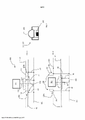
[0052] Preferivelmente, uma unidade de processamento é provida programada para ativar o dito acionador de posicionamento de maneira tal a mover o dito elemento de deformação na direção do dito pneu para aplicar uma força a uma primeira porção da superfície do dito pneu de maneira tal a gerar uma primeira porção de superfície deformada.[0052] Preferably, a processing unit is provided programmed to activate said positioning driver in such a way as to move said deformation element towards said tire to apply a force to a first portion of the surface of said tire in such a way to generate a first deformed surface portion.
[0053] Preferivelmente, uma unidade de processamento é provida programada para ativar o dito acionador de posicionamento de maneira tal a remover a dita primeira força da dita primeira porção da superfície do dito pneu.[0053] Preferably, a processing unit is provided programmed to activate said positioning driver in such a way as to remove said first force from said first portion of the surface of said tire.
[0054] Preferivelmente, o aparelho compreende um unidade de disco e de controle programado para acionar a dita primeira fonte de luz de maneira tal a iluminar a dita primeira porção da superfície deformada do dito pneu, mantendo a dita segunda fonte de luz inativa durante dita deformação da dita primeira porção da superfície.[0054] Preferably, the apparatus comprises a disk and control unit programmed to drive said first light source in such a way as to illuminate said first portion of the deformed surface of said tire, keeping said second light source inactive during said deforming said first portion of the surface.
[0055] Preferivelmente, a unidade de disco e de controle é programada para controlar a dita câmera de maneira tal a adquirir uma primeira imagem da dita primeira porção da superfície deformada iluminada pela dita primeira fonte de luz.[0055] Preferably, the disk and control unit is programmed to control said camera in such a way as to acquire a first image of said first portion of the deformed surface illuminated by said first light source.
[0056] Preferivelmente, a unidade de disco e de controle é programada para acionar a dita segunda fonte de luz de maneira tal a iluminar uma segunda porção da superfície não deformada do dito pneu pelo menos parcialmente diferente da dita primeira porção da superfície.[0056] Preferably, the disk and control unit is programmed to drive said second light source in such a way as to illuminate a second portion of the undeformed surface of said tire at least partially different from said first portion of the surface.
[0057] Preferivelmente, a unidade de disco e de controle é programada para controlar a dita câmera de maneira tal a adquirir uma segunda imagem da dita segunda porção da superfície não deformada iluminada pela dita segunda radiação de luz.[0057] Preferably, the disk and control unit is programmed to control said camera in such a way as to acquire a second image of said second portion of the undeformed surface illuminated by said second light radiation.
[0058] Preferivelmente, a dita unidade de processamento é programada para processar a dita primeira imagem e a dita segunda imagem, de maneira tal a detectar possíveis defeitos na dita primeira porção da superfície e na dita segunda porção da superfície do dito pneu.[0058] Preferably, said processing unit is programmed to process said first image and said second image, in such a way as to detect possible defects in said first surface portion and in said second surface portion of said tire.
[0059] O Requerente considera que o fornecimento de um método e um aparelho no qual um único dispositivo é capaz de realizar diferentes tipos de análise para detectar diferentes tipos de defeitos torna o método para verificar um pneu mais rápido e mais confiável, com baixo custo. O Requerente, de fato, estudou e proveu um método e um aparelho no qual é possível minimizar o número de dispositivos necessários para realizar muitas medições diferentes usando uma primeira fonte aperfeiçoada para a iluminação de defeitos visíveis por meio de compressão em uma primeira porção do pneu em combinação com uma segunda fonte para iluminar uma segunda porção do pneu de uma maneira aperfeiçoar para detectar um outro tipo de defeito.[0059] The Applicant considers that providing a method and an apparatus in which a single device is capable of performing different types of analysis to detect different types of defects makes the method for checking a tire faster and more reliable, with low cost . The Applicant has, in fact, studied and provided a method and an apparatus in which it is possible to minimize the number of devices needed to carry out many different measurements using an improved first source for illuminating visible defects by means of compression in a first portion of the tire in combination with a second source for illuminating a second portion of the tire in an improved manner for detecting another type of defect.
[0060] A presente invenção, em pelo menos um dos aspectos mencionados anteriormente, também pode ter uma ou mais das características preferidas descritas daqui em diante.[0060] The present invention, in at least one of the aforementioned aspects, may also have one or more of the preferred features described hereinafter.
[0061] Preferivelmente, a dita primeira fonte de luz é adequada para emitir radiação de luz difusa e a dita segunda fonte de luz é adequada para emitir radiação de luz rasante.[0061] Preferably, said first light source is suitable for emitting scattered light radiation and said second light source is suitable for emitting grazing light radiation.
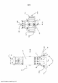
[0062] Preferivelmente, a dita segunda fonte de luz compreende uma primeira fonte subluminosa que emite uma primeira radiação subluminosa e uma segunda fonte subluminosa que emite uma segunda radiação subluminosa, na qual para cada ponto da dita segunda superfície da dita primeira radiação subluminosa e da dita segunda radiação subluminosa vem, respectivamente, de dois meio-espaços opostos com relação a um plano óptico da dita câmera.[0062] Preferably, said second light source comprises a first subluminous source emitting a first subluminous radiation and a second subluminous source emitting a second subluminous radiation, in which for each point of said second surface of said first subluminous radiation and the said second subluminous radiation comes, respectively, from two opposite half-spaces with respect to an optical plane of said camera.
[0063] Vantajosamente, este arranjo particular das fontes luminosas torna possível a ambas chegar particularmente perto do o pneu quando a compressão do mesmo é realizada para detectar um primeiro tipo de defeitos na primeira porção da superfície, e iluminar corretamente e com a potência necessária para identificar defeitos que estariam presentes na segunda porção da superfície.[0063] Advantageously, this particular arrangement of the light sources makes it possible for both to get particularly close to the tire when the tire is compressed in order to detect a first type of defects in the first portion of the surface, and to illuminate correctly and with the necessary power to identify defects that would be present in the second portion of the surface.
[0064] Mais preferivelmente, prevê-se arranjar a dita primeira fonte subluminosa e a dita segunda fonte subluminosa simetricamente com relação à dita primeira fonte de luz.[0064] More preferably, provision is made for arranging said first subluminous source and said second subluminous source symmetrically with respect to said first light source.
[0065] Uma simetria nas fontes, neste caso da segunda fonte que compreende uma primeira subfonte e uma segunda subfonte, que estão arranjadas nos dois lados do plano óptico do sistema de detecção, permite comparação mais fácil das imagens detectadas pela câmera, enquanto que a segunda porção da superfície é iluminada com a primeira radiação subluminosa ou com a segunda radiação subluminosa. Estas iluminações são diferentes para suas diferentes proveniências especulares.[0065] A symmetry in the sources, in this case the second source comprising a first subsource and a second subsource, which are arranged on both sides of the optical plane of the detection system, allows easier comparison of the images detected by the camera, while the second portion of the surface is illuminated with the first subluminous radiation or with the second subluminous radiation. These illuminations are different for their different specular origins.
[0066] Preferivelmente, iluminação com uma primeira radiação de luz compreende iluminação a dita primeira porção da superfície ou a dita segunda porção da superfície com uma primeira radiação de luz difusa.[0066] Preferably, illuminating with a first light radiation comprises illuminating said first surface portion or said second surface portion with a first diffused light radiation.
[0067] Preferivelmente, iluminação com uma segunda radiação de luz compreende iluminação a dita segunda porção da superfície com uma primeira radiação subluminosa rasante ou uma segunda radiação subluminosa rasante.[0067] Preferably, illumination with a second light radiation comprises illuminating said second surface portion with a first grazing subluminous radiation or a second grazing subluminous radiation.
[0068] A primeira fonte de luz preferivelmente emite uma radiação na primeira porção da superfície ou na segunda porção da superfície que, no nível da primeira porção da superfície ou segunda porção da superfície, é difusa, enquanto que a primeira fonte subluminosa ou segunda fonte subluminosa emite uma radiação na segunda porção da superfície que, no nível da segunda porção da superfície é rasante. A primeira porção da superfície, deformada pela compressão, preferivelmente somente precisa de luz difusa para identificar defeitos, enquanto que a segunda porção da superfície preferivelmente precisa de uma iluminação com luz rasante e, mais preferivelmente, com dois diferentes tipos de radiação, rasante e difusa, de maneira tal a obter a aquisição de pelo menos duas imagens para a mesma segunda porção da superfície, cada com diferente iluminação, que pode ser comparada uma com a outra para identificar os defeitos na segunda porção da superfície.[0068] The first light source preferably emits a radiation in the first surface portion or in the second surface portion which, at the level of the first surface portion or second surface portion, is diffuse, while the first subluminous source or second source subluminosa emits a radiation in the second portion of the surface which, at the level of the second portion of the surface is grazing. The first portion of the surface, deformed by compression, preferably only needs diffused light to identify defects, while the second portion of the surface preferably needs illumination with grazing light and, more preferably, with two different types of radiation, grazing and diffused. , in such a way as to obtain the acquisition of at least two images for the same second portion of the surface, each with different illumination, which can be compared one with the other to identify the defects in the second portion of the surface.
[0069] Preferivelmente, para cada ponto da dita segunda porção da superfície pelo menos 90% da respectiva potência luminosa total da dita primeira radiação subluminosa e segunda radiação subluminosa incidente no ponto vêm, respectivamente, dos ditos dois meio-espaços opostos definidos pelo dito plano óptico.[0069] Preferably, for each point of said second portion of the surface at least 90% of the respective total luminous power of said first subluminous radiation and second subluminous radiation incident on the point come, respectively, from said two opposite half-spaces defined by said plane optical.
[0070] Mais preferivelmente, para cada ponto da dita segunda porção da superfície toda a respectiva potência luminosa total da dita primeira radiação subluminosa e segunda radiação subluminosa incidente no ponto vêm, respectivamente, dos ditos dois meio-espaços opostos. Desta maneira, o contraste entre as duas iluminações é acentuado.[0070] More preferably, for each point of said second portion of the surface all respective total luminous power of said first subluminous radiation and second subluminous radiation incident on the point respectively come from said two opposite half-spaces. In this way, the contrast between the two lightings is accentuated.
[0071] Preferivelmente, pelo menos 75% da respectiva potência luminosa total da dita segunda radiação de luz incidente em cada ponto da dita segunda porção da superfície forma um primeiro ângulo de incidência de tamanho menor ou igual a 55° com um plano tangente à superfície do dito pneu no dito cada ponto.[0071] Preferably, at least 75% of the respective total luminous power of said second light radiation incident on each point of said second portion of the surface forms a first angle of incidence of size less than or equal to 55° with a plane tangent to the surface of said tire on said each point.
[0072] Preferivelmente, pelo menos 75%, mais preferivelmente pelo menos 90%, da respectiva potência luminosa total da dita primeira radiação subluminosa e segunda radiação subluminosa incidente em cada ponto da dita segunda porção da superfície forma um primeiro ângulo de incidência de tamanho menor ou igual a 55°, mais preferivelmente menor ou igual a 50° com um plano tangente à superfície do dito pneu no dito cada ponto. Desta maneira, o efeito rasante da luz é acentuado.[0072] Preferably, at least 75%, more preferably at least 90%, of the respective total luminous power of said first subluminous radiation and second subluminous radiation incident on each point of said second portion of the surface forms a first angle of incidence of smaller size or equal to 55°, more preferably less than or equal to 50° with a plane tangent to the surface of said tire at said each point. In this way, the grazing effect of light is accentuated.
[0073] Preferivelmente, pelo menos 75%, mais preferivelmente pelo menos 90%, da respectiva potência luminosa total da dita primeira radiação subluminosa e segunda radiação subluminosa incidente em cada ponto da dita segunda porção da superfície forma um primeiro ângulo de incidência de tamanho maior ou igual a 10°, mais preferivelmente maior ou igual a 20°, ainda mais preferivelmente maior ou igual a 30° com um plano tangente à superfície do dito pneu no dito cada ponto. Desta maneira, a iluminação é possível também com fontes luminosas arranjadas em grande proximidade à superfície do pneu.[0073] Preferably, at least 75%, more preferably at least 90%, of the respective total luminous power of said first subluminous radiation and second subluminous radiation incident on each point of said second portion of the surface forms a first angle of incidence of larger size or equal to 10°, more preferably greater than or equal to 20°, even more preferably greater than or equal to 30° with a plane tangent to the surface of said tire at said each point. In this way, lighting is also possible with light sources arranged in close proximity to the surface of the tyre.
[0074] Preferivelmente pelo menos 75%, mais preferivelmente pelo menos 90%, da respectiva potência luminosa total da dita primeira radiação subluminosa e segunda radiação subluminosa incidente em cada ponto da dita segunda porção da superfície forma um segundo ângulo de incidência menor ou igual a 45°, mais preferivelmente menor ou igual a 30°, em valor absoluto, com um plano de referência perpendicular ao dito plano óptico na dita cada ponto e passando através do normal para a superfície no dito cada ponto. Desta maneira, a diferença na iluminação entre a primeira radiação de luz e a segunda radiação de luz é acentuada.[0074] Preferably at least 75%, more preferably at least 90%, of the respective total luminous power of said first subluminous radiation and second subluminous radiation incident on each point of said second portion of the surface forms a second angle of incidence less than or equal to 45°, more preferably less than or equal to 30°, in absolute value, with a reference plane perpendicular to said optical plane at said each point and passing through the normal to the surface at said each point. In this way, the difference in illumination between the first light radiation and the second light radiation is accentuated.
[0075] Preferivelmente, o fornecimento de um pneu inclui arranjar o dito pneu em um plano de suporte com plano intermediário axial substancialmente paralelo ao plano de suporte, definindo uma porção do lado de apoio e uma porção de lado livre arranjada a uma certa altura com relação ao dito plano de suporte.[0075] Preferably, providing a tire includes arranging said tire on a support plane with intermediate axial plane substantially parallel to the support plane, defining a support side portion and a free side portion arranged at a certain height with with respect to said support plan.
[0076] Preferivelmente, a aplicação de uma primeira força inclui aplicar a dita primeira força contra uma porção da superfície da dita superfície de lado livre.[0076] Preferably, applying a first force includes applying said first force against a surface portion of said free-side surface.
[0077] De maneira a obter suporte correto do pneu durante inspeção, é preferível para ele estar apoiado em um plano de maneira tal que um eixo geométrico de rotação do pneu é substancialmente perpendicular ao plano de suporte. Desta maneira, o pneu é particularmente estável e fácil inspeção de pelo menos metade do dito pneu é permitida.[0077] In order to obtain correct support of the tire during inspection, it is preferable for it to be supported on a plane in such a way that a geometric axis of rotation of the tire is substantially perpendicular to the support plane. In this way, the tire is particularly stable and easy inspection of at least half of said tire is allowed.
[0078] Preferivelmente, a dita primeira força inclui um componente na direção de um eixo geométrico de rotação do dito pneu. O pneu é, assim, “comprimido” ao longo de seu eixo geométrico de rotação de maneira tal a salientar os defeitos como, por exemplo, cortes, que podem ser formados ao longo de uma parede lateral ou um ombro do mesmo.[0078] Preferably, said first force includes a component in the direction of an axis of rotation of said tire. The tire is thus "compressed" along its geometric axis of rotation in such a way as to highlight defects such as, for example, cuts, which can be formed along a sidewall or a shoulder of the tire.
[0079] Mais preferivelmente, o dito componente da dita primeira força é em uma direção na direção do plano médio. Vantajosamente, o pneu é comprimido de fora para dentro, isto é, ele é comprimido aplicando uma força em uma porção da superfície externa do mesmo virada para dentro do pneu.[0079] More preferably, said component of said first force is in a direction towards the midplane. Advantageously, the tire is compressed from the outside inwards, i.e. it is compressed by applying a force to a portion of the outer surface of the tire facing inwards.
[0080] Preferivelmente, prevê-se trazer a dita primeira fonte de luz para a dita primeira porção da superfície deformada a uma distância compreendida entre cerca de 25 mm e cerca de 55 mm, mais preferivelmente entre cerca de 35 mm e cerca de 45 mm. Os defeitos pesquisados, por exemplo, podem ser irregularidades na superfície de um pneu (composto não vulcanizado, alterações no formato, etc.), desnível estrutural, presença de corpos estranhos na superfície. Entre defeitos de desnível estrutural, os assim chamados “deslizamento da carcaça” são particularmente críticos, que são defeitos raros, mas potencialmente muito prejudiciais gerados na região de interface entre duas porções do pneu tendo diferentes características quimicas-físicas como, por exemplo, diferentes compostos.[0080] Preferably, provision is made for bringing said first light source to said first portion of the deformed surface at a distance comprised between about 25 mm and about 55 mm, more preferably between about 35 mm and about 45 mm . The defects investigated, for example, may be irregularities on the surface of a tire (non-vulcanized compound, changes in format, etc.), structural unevenness, presence of foreign bodies on the surface. Among structural unevenness defects, the so-called “carcass slippage” are particularly critical, which are rare but potentially very harmful defects generated in the interface region between two portions of the tire having different chemical-physical characteristics such as, for example, different compounds .
[0081] Tais defeitos são na forma de pequenos cortes, tipicamente se estendendo longitudinalmente, isto é, eles seguem a extensão circular do pneu, distinguido por rebornos perfeitamente correspondentes - entre os quais não há remoção ou falta de material, isto sendo uma característica que os torna particularmente difícil de identificar. O funcionamento do composto pode envolver áreas do pneu arranjadas tanto dentro quanto fora do pneu em si, por exemplo, próximo à superfície interna, abaixo da camada de revestimento enquanto que no lado de fora uma não adesão de dois compostos adjacentes pode gerar cortes tipicamente na área de suporte ou parede lateral.[0081] Such defects are in the form of small cuts, typically extending longitudinally, i.e. they follow the circular extent of the tire, distinguished by perfectly matched ridges - between which there is no removal or lack of material, this being a characteristic that makes them particularly difficult to identify. Compound operation can involve areas of the tire arranged both inside and outside the tire itself, for example close to the inner surface, below the casing layer whilst on the outside a non-adhesion of two adjacent compounds can typically cause cuts in the support area or sidewall.
[0082] Adequadamente deformando uma primeira porção da parede lateral de um pneu a ser verificado é possível diminuir o raio externo da curvatura de uma porção da superfície deformada do pneu, salientando assim possíveis defeitos, em particular funcionamento do composto e outros cortes ou furos, uma vez que a acentuação da convexidade normal externa tende a 'abrir' os rebordos ou perímetros de tais defeitos, tornando-os mais fáceis de identificar no subsequente processamento de imagem.[0082] By suitably deforming a first portion of the sidewall of a tire to be checked, it is possible to decrease the outer radius of curvature of a portion of the deformed surface of the tire, thus highlighting possible defects, in particular the functioning of the compound and other cuts or holes, since the accentuation of the external normal convexity tends to 'open' the edges or perimeters of such defects, making them easier to identify in the subsequent image processing.
[0083] As imagens detectadas desta primeira porção da superfície adequadamente comprimida assim têm uma alta qualidade e/ou contêm informação em número e qualidade, tal como permitir um subsequente processamento automático do último de maneira a detectar possíveis defeitos existentes, tornando os algoritmos para automaticamente detectar defeitos usados para este propósito altamente efetivos.[0083] The images detected from this first portion of the surface properly compressed thus have a high quality and/or contain information in number and quality, such as allowing a subsequent automatic processing of the latter in order to detect possible existing defects, making the algorithms to automatically detect defects used for this purpose are highly effective.
[0084] Este tipo de defeito, de maneira a ser apropriadamente identificado, requer uma iluminação de potência alta relativa e próxima à porção deformada do pneu, isto é, o posicionamento do dispositivo muito próximo ao elemento de impulso, de outra forma o corte aberto pelo elemento de impulso “fecha” assim que uma distância é alcançada da área na qual a deformação acontece.[0084] This type of defect, in order to be properly identified, requires high power lighting relative and close to the deformed portion of the tire, i.e. positioning the device very close to the thrust element, otherwise the open cut by the thrust element “closes” as soon as a distance is reached from the area in which deformation takes place.
[0085] Preferivelmente, prevê-se trazer a dita primeira fonte de luz para a dita segunda porção da superfície a uma distância compreendida entre cerca de 25 mm e cerca de 55 mm, mais preferivelmente entre cerca de 35 mm e cerca de 45 mm. Esta faixa de distâncias foi verificada como ideal para a correta visualização dos defeitos: a distância na qual a primeira fonte de luz é posicionada é um compromisso ideal entre a distância mínima de maneira a não atingir o pneu ou um elemento que aplica uma força de compressão nele.[0085] Preferably, provision is made for bringing said first light source to said second portion of the surface at a distance comprised between about 25 mm and about 55 mm, more preferably between about 35 mm and about 45 mm. This range of distances was verified as ideal for the correct visualization of defects: the distance at which the first light source is positioned is an ideal compromise between the minimum distance so as not to reach the tire or an element that applies a compression force in him.
[0086] Preferivelmente, prevê-se aplicar uma segunda força contra uma terceira porção da superfície do dito pneu de maneira tal a gerar uma segunda porção de superfície deformada, a dita terceira porção da superfície sendo pelo menos parcialmente diferente da dita primeira porção da superfície e da dita segunda porção da superfície do dito pneu.[0086] Preferably, provision is made to apply a second force against a third surface portion of said tire in such a way as to generate a second deformed surface portion, said third surface portion being at least partially different from said first surface portion and said second surface portion of said tire.
[0087] Preferivelmente, prevê-se iluminar a dita segunda porção da superfície deformada do dito pneu com da dita primeira radiação de luz emitida pela dita primeira fonte de luz.[0087] Preferably, provision is made to illuminate said second portion of the deformed surface of said tire with said first light radiation emitted by said first light source.
[0088] Ainda mais preferivelmente, prevê-se adquirir uma terceira imagem da dita porção adicional da superfície deformada iluminada pela dita primeira radiação de luz por meio de um sistema de detecção. Vantajosamente, mais que uma porção da superfície do pneu é verificada por meio do dispositivo aplicando uma força em diferentes porções do pneu. Desta maneira, defeitos em várias posições da superfície podem ser detectados.[0088] Even more preferably, it is envisaged to acquire a third image of said additional portion of the deformed surface illuminated by said first light radiation by means of a detection system. Advantageously, more than one portion of the tire surface is checked by means of the device applying a force to different portions of the tire. In this way, defects at various surface positions can be detected.
[0089] Preferivelmente, a dita primeira porção da superfície ou a dita terceira porção da superfície pertence à dita superfície de lado livre. O pneu é vantajosamente examinado na superfície de lado livre, isto é, a superfície não em contato com um suporte. Preferivelmente, de maneira a examinar a superfície lateral em contato com o pneu substancialmente simétrico à superfície de lado livre, o pneu é girado em 180° perpendicular ao seu eixo geométrico de rotação de maneira tal que a superfície lateral previamente em contato com o suporte se torne a superfície de lado livre e possa ser examinada.[0089] Preferably, said first surface portion or said third surface portion belongs to said free-side surface. The tire is advantageously examined on the free side surface, i.e. the surface not in contact with a support. Preferably, in order to examine the side surface in contact with the tire substantially symmetrical to the free side surface, the tire is rotated through 180° perpendicular to its axis of rotation in such a way that the side surface previously in contact with the support make the side surface free and can be examined.
[0090] Preferivelmente, iluminação da dita segunda porção da superfície inclui iluminação da dita segunda porção da superfície com da dita primeira radiação de luz.[0090] Preferably, illuminating said second surface portion includes illuminating said second surface portion with said first light radiation.
[0091] Preferivelmente, iluminação da dita segunda porção da superfície inclui iluminação da dita segunda porção da superfície com a dita segunda radiação de luz em um tempo diferente com relação ao tempo no qual a dita primeira radiação de luz ilumina a dita segunda porção da superfície.[0091] Preferably, illuminating said second surface portion includes illuminating said second surface portion with said second light radiation at a different time with respect to the time at which said first light radiation illuminates said second surface portion .
[0092] Os tipos de defeitos pesquisados para a segunda porção da superfície do pneu são identificados preferivelmente comparando imagens adquiridas por meio do sistema de detecção em diferentes condições de iluminação, como a primeira radiação de luz e a segunda radiação de luz, de maneira tal que o defeito seja detectável, por exemplo, por meio de uma “subtração” das características detectáveis em uma imagem a partir da outra.[0092] The types of defects surveyed for the second portion of the tire surface are preferably identified by comparing images acquired by means of the detection system in different lighting conditions, such as the first light radiation and the second light radiation, in such a way that the defect is detectable, for example, by means of a “subtraction” of detectable features in one image from the other.
[0093] Preferivelmente, iluminação da dita terceira porção da superfície com uma primeira radiação de luz compreende iluminação da dita terceira porção da superfície com uma primeira radiação de luz difusa. Vantajosamente, o tipo de iluminação da terceira porção é substancialmente análogo ao tipo de iluminação da primeira porção da superfície.[0093] Preferably, illuminating said third surface portion with a first light radiation comprises illuminating said third surface portion with a first diffused light radiation. Advantageously, the type of illumination of the third portion is substantially analogous to the type of illumination of the first portion of the surface.
[0094] Preferivelmente, iluminação da dita segunda porção da superfície inclui iluminação da dita segunda porção da superfície com da dita primeira radiação de luz.[0094] Preferably, illuminating said second surface portion includes illuminating said second surface portion with said first light radiation.
[0095] Preferivelmente, iluminação da dita segunda porção da superfície inclui iluminação da dita segunda porção da superfície com a dita primeira radiação subluminosa em um tempo diferente com relação ao tempo no qual a dita primeira radiação de luz ilumina a dita segunda porção da superfície.[0095] Preferably, illuminating said second surface portion includes illuminating said second surface portion with said first subluminous radiation at a different time with respect to the time at which said first light radiation illuminates said second surface portion.
[0096] Ainda mais preferivelmente, iluminação da dita segunda porção da superfície inclui iluminação da dita segunda porção da superfície com a dita segunda radiação subluminosa em um tempo diferente com relação ao tempo no qual da dita primeira radiação de luz ilumina a dita segunda porção da superfície e a dita primeira radiação subluminosa ilumina a dita segunda porção da superfície.[0096] Even more preferably, illuminating said second portion of the surface includes illuminating said second portion of the surface with said second subluminous radiation at a different time with respect to the time at which said first light radiation illuminates said second portion of the surface and said first subluminous radiation illuminates said second portion of the surface.
[0097] As três diferentes imagens adquiridas a ser processadas são cada com um diferente tipo de iluminação. Isto permite uma comparação de três diferentes imagens e seus processamentos com algoritmos adequados de maneira a salientar os possíveis defeitos na segunda porção da superfície.[0097] The three different acquired images to be processed are each with a different type of illumination. This allows a comparison of three different images and their processing with suitable algorithms in order to highlight possible defects in the second portion of the surface.
[0098] Mais preferivelmente, a aquisição da dita segunda imagem inclui adquirir uma primeira imagem a ser processada quando a dita segunda porção é iluminada pela dita primeira radiação de luz.[0098] More preferably, acquiring said second image includes acquiring a first image to be processed when said second portion is illuminated by said first light radiation.
[0099] Ainda mais preferivelmente, a aquisição da dita segunda imagem inclui adquirir uma segunda imagem a ser processada quando a dita segunda porção é iluminada pela dita primeira radiação subluminosa.[0099] Even more preferably, acquiring said second image includes acquiring a second image to be processed when said second portion is illuminated by said first subluminous radiation.
[00100] Ainda mais preferivelmente, a aquisição da dita segunda imagem inclui adquirir uma terceira imagem a ser processada quando a dita segunda porção é iluminada pela dita segunda radiação subluminosa.[00100] Even more preferably, acquiring said second image includes acquiring a third image to be processed when said second portion is illuminated by said second subluminous radiation.
[00101] As três imagens a ser processadas, duas preferivelmente em luz rasante e uma em luz difusa, são assim vantajosamente processadas para identificar defeitos.[00101] The three images to be processed, two preferably in shallow light and one in diffused light, are thus advantageously processed to identify defects.
[00102] Ainda mais preferivelmente, a dita primeira imagem a ser processada, segunda imagem a ser processada ou terceira imagem a ser processada são constituídas de uma respectiva pluralidade de primeiras imagens lineares, segundas imagens lineares ou terceiras imagens lineares de uma série de porções de superfície linear, contíguas uma à outra ou que parcialmente se sobrepõe, as ditas primeiras imagens lineares, segundas imagens lineares ou terceiras imagens lineares sendo adquiridas em cada porção linear da dita série de porções lineares iluminadas, respectivamente, pela dita primeira radiação de luz, primeira radiação subluminosa e segunda radiação subluminosa em sequência alternada.[00102] Even more preferably, said first image to be processed, second image to be processed or third image to be processed are constituted of a respective plurality of first linear images, second linear images or third linear images of a series of portions of linear surface, contiguous to one another or partially overlapping, said first linear images, second linear images or third linear images being acquired on each linear portion of said series of linear portions illuminated, respectively, by said first radiation of light, first subluminous radiation and second subluminous radiation in alternating sequence.
[00103] Vantajosamente, a dita primeira imagem, a dita segunda imagem, a dita terceira imagem ou as ditas imagens a ser processadas são imagens digitais. Mais preferivelmente elas são imagens formadas de matrizes de pixels.[00103] Advantageously, said first image, said second image, said third image or said images to be processed are digital images. Most preferably they are images formed from arrays of pixels.
[00104] Preferivelmente, a dita primeira imagem ou a dita terceira imagem é constituída de uma respectiva pluralidade de quartas imagens lineares de uma série de porções de superfície linear, contíguas uma à outra ou que parcialmente se sobrepõe, as ditas quartas imagens lineares sendo adquiridas em cada porção linear da dita série de porções lineares iluminadas, respectivamente, pela dita primeira radiação de luz.[00104] Preferably, said first image or said third image is constituted of a respective plurality of fourth linear images of a series of linear surface portions, adjacent to each other or partially overlapping, said fourth linear images being acquired on each linear portion of said series of linear portions respectively illuminated by said first light radiation.
[00105] Um tipo de sistema de detecção para adquirir imagens é, por exemplo, uma câmera linear definindo uma linha de lentes, interseção do plano das lentes em um plano focal no qual ou próximo ao qual a primeira porção da superfície ou a segunda porção da superfície ou a terceira porção da superfície é preferivelmente arranjada quando iluminada. As porções lineares são, desta forma, preferivelmente porções da superfície capazes de ser obtidas próximo às ditas linhas de lentes em sucessão temporal. Por exemplo, uma sucessão como esta das porções lineares pode ser obtida girando o pneu em torno de um eixo geométrico de rotação do mesmo, ou girando o sistema de detecção e as fontes luminosas em torno do pneu. Preferivelmente, pelo menos uma rotação completa de 360° é completada. Mais preferivelmente, uma rotação de mais que 360° é realizada para ter correta sobreposição entre a parte inicial e final (que devem se corresponder) do pneu onde as imagens começam e terminam a ser feitas, respectivamente.[00105] One type of detection system for acquiring images is, for example, a linear camera defining a line of lenses, intersection of the plane of the lenses in a focal plane in which or close to which the first portion of the surface or the second portion of the surface or the third portion of the surface is preferably arranged when illuminated. Linear portions are therefore preferably surface portions capable of being obtained close to said lens lines in temporal succession. For example, a succession like this of linear portions can be obtained by rotating the tire around a geometric axis of rotation of the same, or by rotating the detection system and the light sources around the tire. Preferably, at least one full 360° rotation is completed. More preferably, a rotation of more than 360° is performed to have correct overlap between the starting and ending part (which must match) of the tire where the images begin and end respectively.
[00106] Preferivelmente, prevê-se girar o dito pneu em torno de seu eixo geométrico de rotação; e iluminar o dito pneu em uma pluralidade de posições angulares do dito pneu de maneira a obter uma pluralidade de primeiras imagens ou de segundas imagens ou de terceiras imagens em diferentes posições angulares, uma primeira imagem, ou uma segunda imagem, ou uma terceira imagem para cada posição angular do dito pneu.[00106] Preferably, it is planned to rotate said tire around its geometric axis of rotation; and illuminating said tire at a plurality of angular positions of said tire so as to obtain a plurality of first images or second images or third images at different angular positions, a first image, or a second image, or a third image for each angular position of said tire.
[00107] Vantajosamente, o pneu é girado, em vez do sistema de detecção, uma vez que a primeira operação é mais simples: a rotação do sistema de detecção poderia levar a ele ser danificado ou a aquisição inexata das imagens devido às vibrações induzidas pelo movimento contínuo.[00107] Advantageously, the tire is rotated instead of the detection system, since the first operation is simpler: rotation of the detection system could lead to it being damaged or the inaccurate acquisition of images due to vibrations induced by the continuous motion.
[00108] Preferivelmente, a dita primeira porção da superfície ou a dita terceira porção da superfície é uma porção da superfície externa de uma parede lateral ou de um ombro do dito pneu.[00108] Preferably, said first surface portion or said third surface portion is a portion of the outer surface of a sidewall or shoulder of said tire.
[00109] Preferivelmente, a dita segunda porção da superfície é uma porção da superfície de um talão do dito pneu.[00109] Preferably, said second surface portion is a surface portion of a bead of said tire.
[00110] Preferivelmente, os primeiros tipos de defeitos mencionado, nos quais preferivelmente uma iluminação forte e uma compressão da porção da superfície em exame são necessárias, é um defeito que pode ser encontrado na parede lateral ou ombro do pneu. O segundo tipo de defeito, que exige uma pluralidade de diferentes iluminações, é mais frequente no nível do talão do pneu.[00110] Preferably, the first types of defects mentioned, in which preferably a strong illumination and a compression of the portion of the surface under examination are necessary, is a defect that can be found in the sidewall or shoulder of the tire. The second type of defect, which requires a plurality of different lighting, is more frequent at the tire bead level.
[00111] Preferivelmente, a aplicação de uma primeira força ou uma segunda força inclui aplicar uma pressão constante à dita primeira superfície deformada ou à dita segunda superfície deformada do dito pneu durante a dita rotação.[00111] Preferably, applying a first force or a second force includes applying a constant pressure to said first deformed surface or to said second deformed surface of said tire during said rotation.
[00112] Ainda mais preferivelmente, um valor da dita pressão constante depende de um tipo de dito pneu a ser verificado.[00112] Even more preferably, a value of said constant pressure depends on a type of said tire to be checked.
[00113] Preferivelmente, a aplicação de uma primeira força ou uma segunda força contra uma primeira porção da superfície do dito pneu ou contra uma terceira porção da superfície do dito pneu de maneira tal a gerar uma primeira porção da superfície deformada ou uma segunda porção da superfície deformada inclui manter a dita primeira porção deformada ou segunda porção deformada a uma altura predeterminada com relação a um suporte do dito pneu.[00113] Preferably, the application of a first force or a second force against a first portion of the surface of said tire or against a third portion of the surface of said tire in such a way as to generate a first portion of the deformed surface or a second portion of the deformed surface includes maintaining said first deformed portion or second deformed portion at a predetermined height with respect to a support of said tire.
[00114] Uma deformação pode ser aplicada tanto em força constante quanto altura constante. Ambas podem ser usadas e a mais vantajosa é selecionada de acordo com a aplicação específica ou o tipo de pneu a ser verificado.[00114] A deformation can be applied both at constant force and constant height. Both can be used and the most advantageous one is selected according to the specific application or the type of tire to be checked.
[00115] Mais preferivelmente, a dita altura depende do modelo do pneu a ser verificado.[00115] More preferably, said height depends on the tire model to be checked.
[00116] De fato, nem todos os pneus são do mesmo tamanho ou têm a mesma rigidez e, desta forma, a altura na qual se posicionam na superfície deformada do pneu é preferivelmente selecionada com base nas características do pneu em si.[00116] In fact, not all tires are the same size or have the same stiffness and, therefore, the height at which they are positioned on the deformed surface of the tire is preferably selected based on the characteristics of the tire itself.
[00117] Preferivelmente, é previsto, antes da iluminação da dita segunda porção da superfície, mover a dita segunda fonte de luz de uma primeiro configuração inativa onde ele é controlado para não emitir radiação de luz e na qual a distância da dita segunda fonte de um plano focal da dita câmera é maior que a distância da dita primeira fonte do dito plano focal para uma configuração ativa na qual ele é adaptado para emitir uma segunda radiação de luz e na qual a distância da dita segunda fonte do dito plano focal é igual ou menor que a distância da dita primeira fonte do dito plano focal.[00117] Preferably, it is envisaged, before illuminating said second portion of the surface, to move said second light source from a first inactive configuration where it is controlled not to emit light radiation and in which the distance of said second light source a focal plane of said camera is greater than the distance of said first source from said focal plane for an active configuration in which it is adapted to emit a second light radiation and in which the distance of said second source from said focal plane is equal or less than the distance of said first source from said focal plane.
[00118] Desta maneira, duas iluminações podem ser obtidas movendo a primeira fonte subluminosa e a segunda fonte subluminosa de acordo com se uma ou ambas são necessárias. Quando em configuração inativa, o dispositivo é particularmente compacto e adaptado para ir substancialmente próximo à primeira ou terceira porção da superfície do pneu, que é deformada. Na segunda configuração, com a primeira subfonte e a segunda subfonte “abertas”, é possível obter uma pluralidade de diferentes iluminações da segunda porção da superfície por meio de diferentes fontes. Na segunda configuração, de fato, a compacidade é menos necessária, uma vez que nem os meios de compressão nem a consequente superfície deformada estão presentes, ambos não mais necessários para detectar o defeito procurado, por exemplo, um corte na área do talão.[00118] In this way, two illuminations can be obtained by moving the first subluminous source and the second subluminous source according to whether one or both are required. When in idle configuration, the device is particularly compact and adapted to go substantially close to the first or third portion of the tire surface, which is deformed. In the second configuration, with the first subsource and the second subsource "open", it is possible to obtain a plurality of different illuminations of the second portion of the surface by means of different sources. In the second configuration, in fact, compactness is less necessary, since neither the compression means nor the resulting deformed surface are present, both are no longer necessary to detect the sought defect, for example, a cut in the bead area.
[00119] Preferivelmente, um braço robótico é provido acoplado com uma extremidade para o dito dispositivo. Por meio de um braço robótico, o dispositivo para a iluminação de porções da superfície do pneu é facilmente movido, de maneira tal a alcançar a posição da porção a ser examinada.[00119] Preferably, a robotic arm is provided coupled with an end to said device. By means of a robotic arm, the device for illuminating portions of the tire surface is easily moved, in such a way as to reach the position of the portion to be examined.
[00120] Preferivelmente, a unidade de processamento é programada para mover o dito braço robótico na direção da dita primeira superfície deformada, de maneira tal que a dita primeira fonte de luz do dito dispositivo seja levada a uma distância compreendida entre cerca de 25 mm e cerca de 55 mm da dita superfície deformada, mais preferivelmente entre cerca de 35 mm e cerca de 45 mm.[00120] Preferably, the processing unit is programmed to move said robotic arm towards said first deformed surface, in such a way that said first light source of said device is brought to a distance comprised between about 25 mm and about 55 mm from said deformed surface, more preferably between about 35 mm and about 45 mm.
[00121] Preferivelmente, o dito elemento de deformação inclui um rolo de impulso.[00121] Preferably, said deforming element includes a thrust roller.
[00122] Mais preferivelmente, o rolo de impulso é montado de maneira a ser capaz de girar livremente em torno de seu próprio eixo geométrico. Vantajosamente, a compressão acontece por meio do rolo que apoia contra uma porção da superfície do pneu. O rolo, sendo capaz de girar, mantém a porção comprimida para uma rotação do pneu em torno de seu eixo geométrico de rotação, de maneira tal que a mesma superfície possa ser verificada em qualquer posição angular.[00122] More preferably, the thrust roller is mounted in such a way as to be able to rotate freely around its own geometric axis. Advantageously, compression takes place by means of the roller resting against a portion of the tire surface. The roller, being able to rotate, maintains the compressed portion for a rotation of the tire around its axis of rotation, in such a way that the same surface can be checked in any angular position.
[00123] Preferivelmente, o pneu é estabelecido em rotação e a posição do rolo permanece a mesma, girando em torno de seu eixo geométrico devido à rotação da superfície do pneu com a qual ele está em contato.[00123] Preferably, the tire is set in rotation and the position of the roller remains the same, rotating around its geometric axis due to the rotation of the tire surface with which it is in contact.
[00124] Mais preferivelmente, o eixo geométrico do rolo de impulso fica em um plano que passa através de um eixo geométrico de rotação do pneu e através da direção radial da porção de superfície deformada. Desta maneira, uma compressão da superfície do pneu ideal é realizada.[00124] More preferably, the axis of the thrust roller lies in a plane passing through an axis of rotation of the tire and through the radial direction of the deformed surface portion. In this way, an ideal tire surface compression is realized.
[00125] Preferivelmente, o dito eixo geométrico de rotação do dito rolo de impulso pode ser posicionado em um ângulo predeterminado com um eixo geométrico de rotação do dito pneu. Desta maneira, é possível “seguir” o formato geométrico da superfície do pneu de uma maneira ideal, adequadamente inclinando o eixo geométrico de rotação do rolo, de maneira a aplicar uma pressão correta que não é modificada pelo formato geométrico do pneu.[00125] Preferably, said axis of rotation of said push roller can be positioned at a predetermined angle with an axis of rotation of said tire. In this way, it is possible to “follow” the geometric shape of the tire surface in an ideal way, suitably inclining the geometric axis of rotation of the roller, in order to apply a correct pressure that is not modified by the geometric shape of the tire.
[00126] Preferivelmente, o rolo de impulso pode ser posicionado em duas diferentes posições. Na primeira, o eixo geométrico de rotação do rolo é substancialmente perpendicular ao eixo geométrico de rotação do pneu. Na segunda, o eixo geométrico de rotação do rolo e o eixo geométrico de rotação do pneu formam um ângulo de cerca de 120°.[00126] Preferably, the push roller can be positioned in two different positions. In the first, the axis of rotation of the roller is substantially perpendicular to the axis of rotation of the tire. In the second, the axis of rotation of the roller and the axis of rotation of the tire form an angle of about 120°.
[00127] Preferivelmente, o dito rolo inclui uma porção com seção aumentada em uma porção central ao longo do dito eixo geométrico de rotação e uma porção com seção reduzida em uma extremidade do mesmo ao longo do dito eixo geométrico de rotação. A porção central com seção aumentada é preferivelmente posicionada no ombro ou área da parede lateral onde se deseja procurar defeitos. Entretanto, uma grande porção central pode, em certas situações, criar vibrações que passam sobre os blocos do pneu. Por esta razão, um afunilamento das extremidades axiais do rolo em si é preferível, de maneira tal que a área da superfície envolvida pela compressão do rolo seja limitada e ajustável.[00127] Preferably, said roller includes a portion with increased section at a central portion along said axis of rotation and a portion with reduced section at one end thereof along said axis of rotation. The central portion with enlarged section is preferably positioned in the shoulder or sidewall area where it is desired to search for defects. However, a large central portion can, in certain situations, create vibrations that pass over the tire blocks. For this reason, a taper of the axial ends of the roller itself is preferable, such that the surface area encompassed by roller compression is limited and adjustable.
[00128] Características e vantagens adicionais ficarão mais evidentes a partir da descrição detalhada de algumas modalidades do exemplo, mas não exclusivas, de um método e um dispositivo para verificar pneus, de acordo com a presente invenção. Uma descrição como esta será descrita daqui em diante em mais detalhes com referência às figuras em anexo, providas somente para propósitos de indicação e, desta forma, não limitantes, em que: - a figura 1 mostra uma vista em perspectiva parcial e esquemática, parcialmente em seção e parcialmente em termos de blocos funcionais, de um aparelho para verificar pneus em uma linha de produção de pneu; - a figura 2 mostra uma vista em perspectiva parcial e esquemática do aparelho para verificar pneus de acordo com a presente invenção da figura 1 em uma etapa operacional; - a figura 3 mostra o aparelho da figura 2 em uma diferente etapa operacional; - a figura 3a mostra um detalhe do aparelho da figura 3 em escala ampliada; - a figura 4 mostra o aparelho das figuras 2 a 3 em uma etapa operacional adicional; - a figura 4a mostra uma vista de cima do aparelho na configuração operacional da figura 4; - a figura 5 mostra uma vista lateral parcial e esquemática de um detalhe do aparelho da figura 2 ou 3; - a figura 6 mostra uma vista lateral parcial e esquemática de um detalhe do aparelho da figura 4; - a figura 7 mostra uma vista lateral esquemática de um detalhe da figura 5 ou 6; - a figura 8 mostra uma vista em perspectiva parcial e esquemática de um detalhe do aparelho da figura 2 ou 3; - a figura 9a mostra uma vista em perspectiva de um dispositivo para verificar pneus em uma configuração operacional de acordo com a presente invenção; - a figura 9b mostra uma vista em perspectiva do dispositivo para verificar pneus da figura 9a em uma configuração operacional diferente; - a figura 10 mostra uma vista de cima do dispositivo da figura 9a; - a figura 11 mostra uma vista frontal do dispositivo da figura 9a; - a figura 12 mostra uma vista de cima do dispositivo da figura 9b; e - a figura 13 mostra uma vista frontal do dispositivo da figura 9b.[00128] Additional features and advantages will become more evident from the detailed description of some exemplary, but not exclusive, embodiments of a method and a device for checking tires, according to the present invention. A description like this will be described hereafter in more detail with reference to the attached figures, provided for indication purposes only and therefore not limiting, in which: - figure 1 shows a schematic partial perspective view, partly in section and partly in terms of functional blocks, of an apparatus for checking tires on a tire production line; - figure 2 shows a partial and schematic perspective view of the apparatus for checking tires according to the present invention of figure 1 in an operational stage; - figure 3 shows the apparatus of figure 2 in a different operating stage; - figure 3a shows a detail of the apparatus of figure 3 in an enlarged scale; - figure 4 shows the apparatus of figures 2 to 3 in an additional operating stage; - figure 4a shows a top view of the apparatus in the operational configuration of figure 4; - figure 5 shows a partial and schematic side view of a detail of the device in figure 2 or 3; - figure 6 shows a partial and schematic side view of a detail of the device in figure 4; - figure 7 shows a schematic side view of a detail of figure 5 or 6; - figure 8 shows a partial and schematic perspective view of a detail of the apparatus of figure 2 or 3; - figure 9a shows a perspective view of a device for checking tires in an operational configuration according to the present invention; - figure 9b shows a perspective view of the device for checking the tires of figure 9a in a different operating configuration; - figure 10 shows a top view of the device of figure 9a; - figure 11 shows a front view of the device of figure 9a; - figure 12 shows a top view of the device of figure 9b; and - figure 13 shows a front view of the device of figure 9b.
[00129] Um aparelho para verificar pneus em uma linha de produção de pneu de acordo com a presente invenção é globalmente indicado com 1 e apresentado na figura 1. No geral, o mesmo numeral de referência será usado para possíveis modalidades variantes de elementos similares.[00129] An apparatus for checking tires on a tire production line according to the present invention is globally indicated with 1 and shown in figure 1. In general, the same reference numeral will be used for possible variant embodiments of similar elements.
[00130] O aparelho 1 compreende um suporte 102 (somente visível na figura 1) adaptado para suportar um pneu 200 em uma parede lateral e para girá-la em torno de seu eixo geométrico de rotação 201, tipicamente arranjado de acordo com a vertical. O suporte 102 é tipicamente acionado por um membro de movimentação não descrito e ilustrado de qualquer, uma vez que ele pode, como um exemplo, ser do tipo conhecido. O suporte para o pneu pode possivelmente ser configurado para fechar, por exemplo, o respectivo talão de suporte. O pneu 200 apoiado no suporte, desta forma, define uma superfície de lado livre ou parede lateral livre, representando aquela porção da superfície que não apoia no suporte e virada, em um sistema de eixo geométricos de coordenada com um eixo geométrico Z perpendicular ao plano do suporte, para cima.[00130] The apparatus 1 comprises a support 102 (only visible in figure 1) adapted to support a
[00131] O pneu 200 tem uma estrutura substancialmente toroidal em torno do eixo geométrico de rotação 201, e tem um plano intermediário axial 242 (representado na seção por uma linha pontilhada nas figuras 2, 3 e 4) perpendicular ao eixo geométrico de rotação 201. O pneu é constituído de uma coroa 203 e paredes laterais 204. Por sua vez, as últimas são cada constituída de uma área de ombro 205, uma área de talão 206 e uma área radialmente central ou de parede lateral 207 interposta entre o ombro e o talão.[00131] The
[00132] Tipicamente, conforme representado agora nas figuras 2 e 3, o aparelho 1 compreende um braço robótico 220 no qual um dispositivo 10 é montado e, em particular, o dispositivo 10 compreende um membro de fixação 19 para acoplamento com uma extremidade do braço robótico 220. O braço robótico 220 representado de uma maneira muito esquemática na figura 2 é preferivelmente um braço robótico antropomórfico. Ainda mais preferivelmente, ele é um braço robótico antropomórfico com pelo menos 5 eixo geométricos.[00132] Typically, as shown now in figures 2 and 3, the apparatus 1 comprises a
[00133] Preferivelmente, o aparelho 1 também inclui um elemento de deformação 130. O elemento de deformação 130 é configurado para aplicar, por meio de contato físico, uma força de compressão em uma superfície de contato externa que pertence a uma porção de uma parede lateral do pneu 200 de maneira a elasticamente deformar uma porção da parede lateral, preferivelmente da superfície de lado livre. Em uma configuração preferida, mostrada como um exemplo nas figuras 2 e 3, a força de compressão (indicada pela seta vertical F nas figuras2 e 3) é direcionada como um eixo geométrico de rotação 201 do pneu 200. Entretanto, de acordo com o Requerente, o presente invenção inclui os casos nos quais a força de compressão tem pelo menos um componente paralelo ao eixo geométrico de rotação 201.[00133] Preferably, the apparatus 1 also includes a deforming
[00134] Preferivelmente, o elemento de deformação 130 compreende um membro de compressão 131 e um acionador de posicionamento 132 adaptado para mover o membro de compressão ao longo da direção da força de compressão. Como um exemplo, o acionador de posicionamento 132 pode ser um cilindro pneumático. Desta forma, o membro de compressão pode ser colocado em contato com ou longe do pneu 200. Preferivelmente, o membro de compressão 131 compreende um rolo de impulso.[00134] Preferably, the deforming
[00135] Preferivelmente, o rolo de impulso é giratório em torno de seu eixo geométrico de rotação, indicado com 117 nas figuras. O eixo geométrico 117 do rolo de impulso sempre senta em um plano que passa através do eixo geométrico do pneu e através da direção radial da porção da parede lateral submetida à deformação (por exemplo, o plano das figuras 2 e 3). Preferivelmente, o eixo geométrico 117 do rolo de impulso, na ausência de forças, em outras palavras em posição de apoio, é perpendicular ao eixo geométrico do pneu. O eixo geométrico do rolo, em operação, pode divergir de uma condição perpendicular como esta com o eixo geométrico do pneu (conforme mostrado, por exemplo, na figura 2) por exemplo, na faixa +30° da condição perpendicular.[00135] Preferably, the thrust roller rotates around its geometric axis of rotation, indicated with 117 in the figures. The
[00136] Além do mais, o rolo de impulso, visível em detalhes na figura 3a, compreende uma seção, tomada em um plano perpendicular ao eixo geométrico de rotação 117, que é substancialmente circular. Um diâmetro da seção é preferivelmente variável, de um diâmetro mínimo presente em uma primeira extremidade 118a e uma segunda extremidade axialmente oposta 118b do dito rolo ao longo do eixo geométrico de rotação 117, a um diâmetro máximo presente em uma área central do rolo.[00136] Furthermore, the thrust roller, visible in detail in Figure 3a, comprises a section, taken in a plane perpendicular to the geometric axis of
[00137] Preferivelmente, o elemento de deformação 130 compreende um membro de movimento radial (não mostrado, por exemplo, um motor elétrico adicional e um sistema de blocos de guia e deslizamento para guiar o movimento radial) adaptado para mover o membro de compressão 131 e o acionador de posicionamento 132 como uma unidade ao longo da direção radial do pneu. Desta forma, o elemento de deformação 130 pode ser removido do pneu quando não estiver em uso.[00137] Preferably, the deforming
[00138] Preferivelmente, o elemento de deformação 130 é adaptado para elasticamente deformar uma porção de uma parede lateral do pneu 200, aplicando uma força de compressão em uma superfície de contato externa que pertence à porção da parede lateral, prensando o rolo de impulso mencionado anteriormente na superfície de contato externa. A força aplicada ou o movimento imposto na superfície de contato externa ao longo de um eixo geométrico de rotação do pneu é predeterminada e depende do tipo de pneu a ser verificado. Os pneus 200 podem ter uma elasticidade e deformabilidade diferentes de acordo com o tipo e modelo e, desta forma, a força aplicada ou a deformação imposta pelo elemento de deformação 130 preferivelmente depende do tipo de pneu 200 a ser verificado.[00138] Preferably, the deforming
[00139] O dispositivo 10, com referência inicial às figuras 5 a 8, compreende um sistema de detecção 104 incluindo uma câmera 105. Preferivelmente, a câmera 105 é uma câmera linear tendo uma linha de lentes 106 que fica em um plano óptico 107 que passa através da câmera em si (visível nas figuras 5, 6 e 8). A presente invenção também considera o caso alternativo no qual a câmera 105 é de um tipo diferente como, por exemplo, uma câmera de matriz. Neste caso, a porção da superfície iluminada e adquirida também é do tipo de matriz. Além do mais, a câmera 105 define um plano focal 121 no qual uma porção a ser iluminada da superfície do pneu está centrada. Preferivelmente, o plano óptico 107 e o plano focal 121 são perpendiculares um ao outro (visível nas figuras5, 6 e 8).[00139] The
[00140] O dispositivo 10 também compreende uma primeira fonte de luz 110 e uma segunda fonte de luz 108 adaptadas para emitir, respectivamente, uma primeira e uma segunda radiação de luz para iluminar uma porção da superfície 202, preferivelmente linear (visível na figura 8), do dito pneu 200 coincidindo com a linha de lentes 106 (por exemplo, quando o porção da superfície é planar) ou próximo à linha de lentes 106 (devido ao formato curvilíneo da superfície do pneu).[00140] The
[00141] O sistema de detecção através da câmera 105 é adaptada para adquirir uma respectiva imagem digital bidimensional da porção da superfície 202 (linear) iluminada por pelo menos uma da primeira e da segunda radiação de luz.[00141] The detection system through the
[00142] Preferivelmente, a segunda fonte de luz 108 compreende uma primeira fonte subluminosa 109a e uma segunda fonte subluminosa 109b. Cada fonte subluminosa 109a e 109b pode compreender um ou mais elementos da fonte. Preferivelmente, cada fonte subluminosa 109a e 109b compreende um único respectivo elemento da fonte 111 e 112, respectivamente. Os dois elementos da fonte 111, 112 são posicionados simetricamente com relação ao plano óptico 107. Preferivelmente, os dois elementos da fonte 111 e 112 respectivamente sentam em lados opostos com relação ao plano óptico e são equidistantes dele.[00142] Preferably, the second
[00143] Preferivelmente, a primeira fonte de luz 110 compreende dois respectivos elementos da fonte 113 distribuídos em ambos os lados do plano óptico 107 e simetricamente com relação a um plano como este.[00143] Preferably, the first
[00144] Cada elemento da fonte 111, 112, 113 tem uma respectiva direção principal de extensão (indicada como um exemplo com as linhas pontilhadas 114 na figura 8) preferivelmente substancialmente paralela ao plano óptico 107 e assim à linha de lentes 106.[00144] Each
[00145] Como um exemplo, os elementos da fonte 111, 112, 113 têm uma dimensão ao longo da direção de extensão principal 114 igual a cerca de 60 mm, e um diâmetro perpendicular à direção de extensão principal mencionada anteriormente 114 igual a cerca de 25 mm. Cada elemento da fonte 111, 112, 113, tipicamente compreende uma pluralidade de fontes de LED 169 arranjadas alinhadas ao longo da direção de extensão principal 114. Preferivelmente, conforme pode ser visto na figura 7, cada elemento da fonte 111, 112, 113, compreende, posicionado acima de cada luz de LED 169, lentes convergentes 170, adaptadas para convergir o feixe de luz emitido pela luz de LED em cerca de 30°. O feixe de luz emitido por cada luz de LED é, desta forma, preferivelmente restrito em um ângulo compreendido entre cerca de 20° e cerca de 40°.[00145] As an example, the
[00146] Nas figuras5, 6 e 8, os elementos das fontes luminosas 111, 112, 113 são mostrados esquematicamente com referência a suas respectivas superfícies emissoras (nas figuras como um exemplo semicircular na forma, entretanto pode ser de qualquer forma) que pode, por exemplo, coincidir com o vidro e/ou difusor protetor transparente.[00146] In figures 5, 6 and 8, the elements of
[00147] Conforme pode ser visto a partir das figuras 5 e 6, o dispositivo, e em particular suas fontes luminosas, pode ser movido de uma primeira configuração operacional para uma segunda configuração operacional e vice-versa.[00147] As can be seen from figures 5 and 6, the device, and in particular its light sources, can be moved from a first operational configuration to a second operational configuration and vice versa.
[00148] Na primeira configuração operacional da figura 5, preferivelmente a distância d1 de cada dos elementos da fonte 113 da primeira fonte de luz 110 do plano óptico 107 é maior que a distância d2, d3 entre cada elemento da fonte 111, 112 da dita segunda fonte de luz 108 e o plano óptico 107.[00148] In the first operational configuration of figure 5, preferably the distance d1 of each of the
[00149] Vantajosamente, na segunda configuração da figura 6, a distância d1 entre a primeira fonte 110 nos elementos da fonte 113 e o plano focal 121 é menor que a distância d2 ou d3 da primeira fonte subluminosa 109a ou segunda fonte subluminosa 109b do plano focal 121. Mais preferivelmente d1 é menor tanto que d2 quanto d3. Ainda mais preferivelmente d2=d3. Preferivelmente, em ambas as configurações, os dois elementos da fonte 113 da primeira fonte de luz 110 são coplanares e definem um plano P1 substancialmente paralelo ao plano focal 121, sendo uma distância d1 dele, isto é, os elementos da fonte 113 da primeira fonte de luz estão na mesma distância do plano focal 121. O plano P1 pode ser definido como o plano que passa através dos pontos de ambos os elementos da fonte 113 da primeira fonte de luz 110 na distância mínima do plano focal 121 (conforme representado na figura 5 e 6), ou como o plano que passa através de uma linha média de ambos os elementos da fonte 113.[00149] Advantageously, in the second configuration of figure 6, the distance d1 between the
[00150] Preferivelmente, as fontes subluminosas 109a e 109b, preferivelmente tanto na primeira quanto na segunda configuração operacional, também são coplanares e definem um plano P2 substancialmente paralelo ao plano focal 121. Preferivelmente, a distância deste plano P2 do plano focal 121 é igual a d2 (con d2=d3). Como para P1, o plano P2 pode ser definido como o plano que passa através dos pontos de ambas as fontes subluminosas 109a e 109b na distância mínima do plano focal 121 (conforme representado na figura 5 e 6), ou o plano que passa através do uma linha média de ambas as fontes subluminosas 109a-109b.[00150] Preferably, the
[00151] Preferivelmente, na primeira e/ou na segunda configuração, a distância d1 é igual a cerca de 77 mm.[00151] Preferably, in the first and/or second configuration, the distance d1 is equal to about 77 mm.
[00152] Mais preferivelmente, na primeira configuração, a distância d1- d2 = d1-d3 é igual a cerca de 32 mm (77 mm a 45 mm).[00152] More preferably, in the first configuration, the distance d1-d2 = d1-d3 is equal to about 32 mm (77 mm to 45 mm).
[00153] Uma modalidade deste dispositivo é representada nas figuras 9a, 9b, e 10 a 13.[00153] An embodiment of this device is represented in figures 9a, 9b, and 10 to 13.
[00154] Cada fonte de luz 108, 110 inclui um suporte, preferivelmente feito de alumínio, no qual os LEDs 169 são fixados. Os suportes são todos indicados com 168 nas figuras em anexo (ver figuras 9a, 9b e 13). Preferivelmente, os LEDs 169 são fixados ao respectivo suporte 168 por meio de uma pasta termo condutora (não visível nas figuras). Vantajosamente, cada suporte 168 também inclui, em uma superfície externa não em contato com os LEDs, um arranjo de barbatana 167 para a dissipação de calor (visível nas figuras 9a e 13).[00154] Each
[00155] A primeira e a segunda fonte elemento 113 da primeira fonte de luz 110 são posicionadas entre duas placas 11, 12 arranjadas substancialmente perpendicular à direção de extensão principal 114 da primeira fonte de luz 110 e substancialmente paralela uma a outra. Entre as duas placas 11, 12, que se estendem a jusante da primeira fonte de luz na direção de emissão da luz, a câmera linear 105 também é posicionada.[00155] The first and
[00156] Estas duas placas 11, 12 são articuladas a uma terceira e uma quarta placa 13, 14, de maneira tal que o eixo geométrico de rotação da terceira e quarta placa assim definida seja substancialmente paralela à direção principal da primeira fonte de luz 110 ou da segunda fonte de luz 108. A terceira placa 13 é firmemente conectada à primeira subfonte 109a da segunda fonte de luz 108, enquanto que a quarta placa 14 é firmemente conectada à segunda fonte subluminosa 109b da segunda fonte de luz 108.[00156] These two
[00157] Terceira e quarta placas 13, 14 são rotativamente movidas por um primeiro e um segundo pistão pneumático 15, 16, visível na condição estendida nas figuras9a e 10. Cada pistão 15, 16 é conectado a uma extremidade na placa a ser movida, e na outra extremidade da primeira placa 11.[00157] Third and
[00158] O movimento das placas 13, 14 através dos pistões significa que o dispositivo 10 pode ser levado na primeira configuração operacional, de maneira tal que aquelas das figuras 9a, 10 e 11 nas quais a segunda fonte de luz 108, isto é, as subfontes 109a e 109b, são levadas “para frente”, isto é, elas estão a partir da câmera 105 com relação à primeira fonte de luz 110 e mais próximo à superfície do pneu a ser iluminado, isto é, mais próxima ao plano focal 121 com relação à primeira fonte de luz 110; ou na segunda configuração, de maneira tal que aquela representada na figura 9b, na qual a segunda fonte de luz 108 é posicionada longe com relação ao plano focal 121, a primeira subfonte 109a e a segunda subfonte 109b são substancialmente dobradas em paralelo ao plano óptico 107 para minimizar um volume dado pelo dispositivo 10 em uma direção perpendicular ao plano óptico 107.[00158] The movement of the
[00159] Preferivelmente, tanto na primeira configuração operacional quanto na segunda configuração operacional, conforme pode ser visto mais claramente nas respectivas figuras 11 e 13, os elementos da fonte da primeira fonte de luz 110 e da segunda fonte de luz 108 são arranjados de maneira tal que para sua extensão total em uma vista perpendicular ao plano óptico 107 eles fiquem entre dois planos perpendiculares à linha de lentes. Em outras palavras, todas da primeira e segunda extremidades das fontes 108 e 110 com relação à direção de extensão principal 114 ficam em um respectivo plano perpendicular à linha de lentes.[00159] Preferably, both in the first operational configuration and in the second operational configuration, as can be seen more clearly in the respective figures 11 and 13, the source elements of the first
[00160] Preferivelmente, o dispositivo 10 compreende uma unidade de disco e de controle 140 configurado para seletivamente ativar uma ou mais da dita primeira fonte de luz 110, e a dita segunda fonte de luz 108 e ativa a câmera linear 105 para adquirir uma respectiva imagem digital bidimensional (em cor ou monocromática) da porção de superfície linear, preferivelmente em sincronia com a ativação de uma ou mais da dita primeira fonte de luz 110 e segunda fonte de luz 108.[00160] Preferably, the
[00161] Preferivelmente, a unidade de disco e de controle 140 é fixa à dita placa de suporte 11 da primeira fonte de luz 110 e da câmera 105 de maneira a enviar sinais relativos ao controle das fontes luminosas 108, 110, sem tempos de espera. Preferivelmente, além do mais, a unidade de disco e de controle 140 é adaptada para controlar a segunda fonte de luz 108 para não emitir nenhuma radiação quando na segunda configuração e emitir radiação de luz quando na primeira configuração.[00161] Preferably, the disk and
[00162] Para maior dissipação de calor, além do mais, a unidade 140 também compreende um arranjo de barbatana 166 (visível na figura 9a).[00162] For greater heat dissipation, moreover, the
[00163] A unidade de processamento 180, por outro lado, (ilustrada na figura 1) é preferivelmente adaptada para controlar os pistões 15, 16 de maneira tal a mover as fontes subluminosas 109a e 109b da segunda fonte de luz 108. Preferivelmente, a unidade de processamento 180 também é adaptada para controlar o elemento de deformação 130 e o braço robótico 220 de maneira a levar o elemento de deformação 130 para o pneu ou para longe dele 200 para deformar, ou não, uma porção da superfície, enquanto que o braço robótico 220 carrega o dispositivo 10 a uma distância predeterminada da superfície do pneu a ser iluminada e a ser verificada.[00163] The
[00164] Preferivelmente, a segunda fonte de luz 108 é adequada para iluminar a linha de lentes 106 com luz rasante. Preferivelmente, a primeira fonte de luz 110 é adaptada para iluminar a linha de lentes 106 com luz difusa.[00164] Preferably, the second
[00165] Preferivelmente, o aparelho 1 é feito para operar de acordo com o método da invenção.[00165] Preferably, apparatus 1 is made to operate according to the method of the invention.
[00166] Uma primeira porção da superfície a ser verificado (sempre indicada com 202) é selecionada na superfície externa do pneu 200. Preferivelmente, mas não exclusivamente, esta porção pertence ao ombro ou à parede lateral do pneu 200. A unidade de processamento 180 pega o dispositivo 10 na segunda configuração das figuras 9b, 12, 13 e 6, enquanto que a unidade de disco e de controle 140 controla a segunda fonte de luz 108 para não emitir nenhuma radiação. O dispositivo 10 é particularmente compacto para o posicionamento das fontes subluminosas 109a e 109b substancialmente paralelo ao plano óptico 107.[00166] A first portion of the surface to be checked (always indicated with 202) is selected on the outer surface of the
[00167] A unidade de processamento 180 controla o elemento de deformação 130 para fazer contato com o pneu, preferivelmente na sua parede lateral 204, de maneira a aplicar uma força contra ele e deformar uma primeira porção da superfície do mesmo incluindo a primeira porção selecionada, conforme pode ser visto na figura 2. Preferivelmente, conforme representado na figura 2, a primeira porção da superfície é uma porção do ombro 205 do pneu 200. Preferivelmente, toda a porção da parede lateral restante 204 do pneu 200 permanece não deformada. Como um exemplo, a força de compressão, tal como para deformar a porção da parede lateral 204 de maneira tal que a excursão máxima, tomada entre todos os pontos da dita porção da parede lateral, entre a posição na ausência de forças e a posição deformada, a excursão sendo medida ao longo da direção da força de compressão, é igual a um calor compreendido entre cerca de 10 e cerca de 20 mm.[00167] The
[00168] O dispositivo 10 na configuração compacta da figura 9b pode substancialmente ficar próximo ao elemento de deformação 130 (novamente visto na figura 2) para iluminar e adquirir imagens da primeira porção da superfície do pneu 200 deformadas pelo elemento de deformação 130. A unidade de processamento 180 controla o braço robótico 220 para levar a primeira fonte de luz 110 para a superfície do pneu 200 e o elemento de deformação 130, de maneira tal que uma porção de superfície linear dentro da primeira porção deformada pelo menos parcialmente coincida com ou esteja próxima à linha de lentes 106 no plano focal 121. A porção linear também pertence, pelo menos parcialmente, à primeira porção da superfície deformada no lado do elemento de deformação 130. Preferivelmente, a distância entre elemento de deformação 130 e, em particular, o rolo de impulso e o dispositivo 10 é compreendida entre cerca de 30 mm e cerca de 50 mm.[00168] The
[00169] A unidade de processamento 180, desta forma, controla o membro de movimentação do suporte 102 para ajustar o pneu 200 em rotação.[00169] The
[00170] Como uma função do sinal da posição angular recebido pelo codificador, com a rotação do pneu em progresso, a unidade de disco e de controle 140 cilindricamente ativa em sequência rápida da primeira fonte de luz 110 e da câmera linear 105 para adquirir uma respectiva imagem digital bidimensional (em cor ou monocromática) da respectiva porção de superfície linear em sincronia com a ativação da primeira fonte de luz 110. A unidade de controle 140 controlará, em paralelo, a ligação dos elementos da fonte 113 da primeira fonte de luz 110 que funcionam em sincronia com a câmera linear 105. Os dois elementos da fonte 113, desta forma, ligam ao mesmo tempo.[00170] As a function of the angular position signal received by the encoder, with tire rotation in progress, the cylindrical disk and
[00171] Mais preferivelmente, a unidade de disco e de controle 140 controla a primeira fonte de luz 110 para emitir uma radiação difusa na primeira porção da superfície 202 do pneu 200, por exemplo, a uma frequência predeterminada. Uma frequência estroboscópica como esta é, por exemplo, igual a 0,1 ms. A unidade de disco e de controle 140, além do mais, controla a câmera 105 para adquirir uma imagem da primeira porção da superfície iluminada pela primeira fonte de luz em sincronia com a iluminação da mesma. Desta forma, uma imagem da primeira porção da superfície do pneu 200 iluminada é adquirida pela câmera 105 toda vez que a primeira fonte de luz 110 que ilumina a porção com luz difusa é ligada.[00171] More preferably, the disk and
[00172] Uma vez que a rotação do pneu 200 desejada foi realizada para examinar a porção da superfície desejada, preferivelmente pelo menos uma rotação completa para adquirir toda a extensão circular, uma imagem digital de um “anel” do pneu é obtida, feita com todas as imagens digitais da sequência das porções lineares cada iluminada com a primeira fonte de luz. Para uma imagem completa em 360°, por exemplo, 25.000 imagens lineares únicas são usadas.[00172] Once the desired rotation of the
[00173] Opcionalmente, uma terceira porção da superfície do pneu é selecionada, preferivelmente mas não necessariamente novamente pertencendo à parede lateral 204 da superfície externa do mesmo, mas diferente - pelo menos parcialmente - da primeira porção. O elemento de deformação 130 assim pode ser posicionado, preferivelmente novamente através da unidade de processamento do aparelho 180, em uma porção da superfície do pneu diferente 200, de maneira tal a deformar uma segunda porção da superfície do pneu, incluindo a terceira porção selecionada. Desta maneira, uma nova análise pode ser realizada, trazendo o dispositivo 10 para a nova posição de maneira a obter uma iluminação da porção adicional deformada da superfície externa do pneu. Ver, por exemplo, a diferença entre a posição do elemento de deformação 130 na figura 2 e na figura 3 e a consequente diferente posição do dispositivo 10 das duas figuras: na figura 2 uma porção da superfície externa do ombro 205 do pneu é iluminada pela primeira fonte de luz 110, enquanto que na figura 3 uma porção da superfície externa da área central 207 da parede lateral 204 do pneu 200 é iluminada pela primeira fonte de luz 110. Além do mais, na figura 2, o eixo geométrico de rotação 117 do rolo de impulso, posicionado no ombro 205, é inclinado com relação ao plano definido pelo suporte do pneu 200, enquanto que na figura 3, o eixo geométrico de rotação 117 do rolo de impulso é substancialmente perpendicular ao eixo geométrico de rotação 201, assim paralelo ao plano mencionado anteriormente definido pelo suporte 102 do pneu 200.[00173] Optionally, a third portion of the surface of the tire is selected, preferably but not necessarily again belonging to the
[00174] Além do mais, uma segunda porção a superfície externa do pneu 200 a ser verificada é selecionada. Preferivelmente, mas não necessariamente, esta segunda porção pertence ao talão 206 do pneu 200.[00174] Furthermore, a second portion of the outer surface of the
[00175] A unidade de processamento 180 controla o elemento de deformação 130 para afastar da superfície do pneu de maneira tal que nenhuma força de deformação seja aplicada nele. Além do mais, a unidade 180 controla os pistões 15, 16 de maneira tal a ter a segunda fonte de luz 108 na configuração operacional das figuras 9a, 10, 11 e 5. Além do mais, a unidade de processamento 180 controla o braço robótico 220 para trazer o dispositivo 10 para a segunda porção da superfície, parte do talão do pneu, e controla o membro de movimentação do suporte 102 para ajustar o pneu 200 na rotação. A configuração alcançada é representada nas figuras 4 e 4a.[00175] The
[00176] A primeira fonte de luz 110 e a segunda fonte de luz 108 também são controladas pela unidade de disco e de controle 140 para emitir uma radiação na segunda porção da superfície 202 do pneu 200. Preferivelmente, a primeira fonte de luz 110 emite radiação difusa na segunda porção da superfície, enquanto que a segunda fonte de luz 108 emite radiação rasante, que vem de meio-espaços opostos com relação ao plano óptico 107 graças ao fornecimento das duas subfontes 109a e 109b. Preferivelmente, todas as fontes luminosas emitem radiação de luz para iluminar o segunda porção da superfície do pneu, por exemplo, a uma frequência predeterminada. Uma frequência estroboscópica como esta é, por exemplo, igual a 0,064 ms. Preferivelmente, as fontes luminosas, isto é, a primeira fonte de luz 110, a primeira fonte subluminosa 109a e a segunda fonte subluminosa 109b são ligadas alternadamente, isto é, em um dado período de tempo somente a primeira fonte 110 ou a primeira subfonte 109a ou a segunda fonte subluminosa 109b da segunda fonte 108 ilumina a segunda porção da superfície do pneu. A unidade de disco e de controle 140, além do mais, preferivelmente controla a câmera 105 de maneira tal a adquirir uma imagem da segunda porção da superfície iluminada pela primeira fonte ou pela primeira subfonte ou pela segunda fonte subluminosa em sincronia com a iluminação da mesma. Desta forma, vantajosamente, a câmera 105 adquire uma imagem da segunda porção da superfície do pneu 200 iluminada toda vez que a primeira fonte de luz 110 é ligada, que ilumina a porção com luz difusa, uma imagem da segunda porção da superfície do pneu 200 iluminada toda vez que a primeira fonte subluminosa 109a é ligada, que ilumina a segunda porção com luz rasante de um lado do plano óptico 107 e uma imagem da segunda porção da superfície do pneu 200 iluminada toda vez que a segunda fonte subluminosa 109b é ligada, que ilumina a segunda porção com luz rasante do outro lado do plano óptico 107. Desta maneira, vantajosamente, para cada segunda porção da superfície, três diferentes imagens a ser processadas são adquiridas na qual a mesma porção é iluminada com uma radiação tendo características diferentes. Desta maneira, é possível adquirir tanto uma imagem em luz difusa quanto duas imagens em luz rasante da mesma porção da superfície. Estas três imagens também podem formar diferentes porções e uma única imagem bidimensional, na qual uma primeira porção é obtida com a luz rasante, uma segunda porção com luz rasante de uma primeira direção do plano óptico (por exemplo, da direita) e uma terceira porção com luz rasante de uma segunda direção oposta do plano óptico (por exemplo, da esquerda).[00176] The first
[00177] Preferivelmente, cada imagem é uma imagem linear.[00177] Preferably, each image is a linear image.
[00178] Preferivelmente, o aparelho compreende um codificador (não mostrado) para detectar a posição angular do suporte, a unidade de disco e de controle sendo configurada para ativar a dita primeira fonte de luz 110, e segunda fonte de luz 108, e para controlar o sistema de detecção como uma função de um sinal da posição angular do suporte enviado pelo codificador.[00178] Preferably, the apparatus comprises an encoder (not shown) for detecting the angular position of the support, the disc and control unit being configured to activate said first
[00179] Como um exemplo, a diferença de tempo entre a aquisição da primeira e segunda imagem linear, bem como entre a segunda e terceira imagem linear e então ciclicamente entre a primeira e terceira imagem linear, é menor que 0,2 milissegundos.[00179] As an example, the time difference between acquiring the first and second linear image, as well as between the second and third linear image and then cyclically between the first and third linear image, is less than 0.2 milliseconds.
[00180] Desta forma, substancialmente para a mesma porção da superfície, três imagem lineares são obtidas, cada com uma iluminação diferente.[00180] In this way, for substantially the same portion of the surface, three linear images are obtained, each with a different illumination.
[00181] A expressão “substancialmente a dita porção da superfície”, ou, mais tarde, “substancialmente uma mesma porção da superfície”, significa que a primeira e segunda ou terceira fonte de luz ilumina duas (ou três) respectivas porções da superfície que podem ser espacialmente deslocadas de uma para outra, mas são comparáveis de acordo com a presente invenção, isto é, apresentam os mesmos elementos substancialmente na mesma posição. Por exemplo, as duas (ou três) superfícies podem ser deslocadas, no plano da superfície em si, em uma distância menor que 0,2 mm, preferivelmente menor ou igual a 0,1 mm. Vantajosamente, a dita distância é menor ou igual à dimensão linear da superfície associada com um pixel (o último como um exemplo sendo igual a 0,1 mm), no caso em que o sistema de detecção inclui uma câmera, por exemplo, matriz ou linear. Em outras palavras, cada pixel da primeira imagem mostra uma porção da microssuperfície que é menor que 0,2 mm longe da porção da microssuperfície mostrada pelo pixel da segunda imagem que corresponde a cada dito pixel.[00181] The expression "substantially said portion of the surface", or, later, "substantially the same portion of the surface", means that the first and second or third light source illuminates two (or three) respective portions of the surface that they can be spatially displaced from one to another, but they are comparable according to the present invention, i.e. they present the same elements in substantially the same position. For example, the two (or three) surfaces can be offset, in the plane of the surface itself, by a distance of less than 0.2 mm, preferably less than or equal to 0.1 mm. Advantageously, said distance is less than or equal to the linear dimension of the surface associated with a pixel (the latter as an example being equal to 0.1 mm), in the case where the detection system includes a camera, e.g. matrix or linear. In other words, each pixel of the first image shows a portion of the microsurface that is less than 0.2 mm away from the portion of the microsurface shown by the pixel of the second image that corresponds to each said pixel.
[00182] Em outras palavras, as três imagens podem ser substancialmente sobrepostas pixel por pixel, embora a porção de superfície linear real associada com uma única imagem linear não coincide exatamente para as três imagens, devido à rotação do pneu que ocorreu nesse ínterim. Entretanto, a escolha da frequência de aquisição das imagens e da velocidade de rotação é de maneira tal que as três imagens são entrelaçadas e assim comparáveis pixel por pixel. Vantajosamente, cada pixel da primeira (ou segunda ou terceira) imagem mostra uma porção da microssuperfície que difere da porção da microssuperfície mostrada pelo pixel da segunda (ou respectivamente terceira ou primeira) imagem que corresponde a cada do dito pixel além da dimensão da superfície linear associada com um pixel, como um exemplo o deslocamento espacial sendo igual a cerca de uma terceira de um pixel. Desta maneira, as três imagens são entrelaçadas e a aquisição das três imagem lineares acontece em um período de tempo durante o qual o pneu girou por uma porção igual a um pixel (como um exemplo igual a cerca de 0,1 mm).[00182] In other words, the three images can be substantially superimposed pixel by pixel, although the actual linear surface portion associated with a single linear image does not exactly match for the three images, due to the rotation of the tire that has occurred in the interim. However, the choice of image acquisition frequency and rotation speed is such that the three images are interlaced and thus comparable pixel by pixel. Advantageously, each pixel of the first (or second or third) image shows a portion of the microsurface that differs from the portion of the microsurface shown by the pixel of the second (or respectively third or first) image that corresponds to each of said pixel beyond the dimension of the linear surface. associated with a pixel, as an example the spatial offset being equal to about one-third of a pixel. In this way, the three images are interlaced and the acquisition of the three linear images takes place in a period of time during which the tire has rotated by a portion equal to one pixel (as an example equal to about 0.1 mm).
[00183] Uma vez que a rotação do pneu desejada foi realizada para examinar a porção da superfície desejada, preferivelmente pelo menos uma rotação completa para adquirir toda a extensão circular, uma única imagem digital é obtida que é feita com todas as imagens digitais da sequência de porções lineares, cada iluminada com uma respectiva fonte de luz. A unidade de processamento 180 recebe uma imagem como esta do sistema de detecção 104 e extrai a primeira, segunda e terceira imagem correspondente de toda a porção da superfície dela desejada.[00183] Once the desired tire rotation has been performed to examine the desired surface portion, preferably at least one complete rotation to acquire the entire circular extent, a single digital image is obtained which is taken from all digital images in the sequence of linear portions, each illuminated with a respective light source.
[00184] No caso em que uma única imagem é adquirida como descrito anteriormente formada a partir de uma porção com luz difusa [A], uma porção com luz rasante dx [B] e uma porção com rasante esquerda [C], uma sucessão repetida até que todo pneu seja adquirido, uma imagem geral é obtida formada pela sequência ABCABCABCABCABCABCABCABCABC No processamento, esta imagem é dividida em três imagens efetivas, obtendo AAAAAAAA... BBBBBBBB... CCCCCCCC.[00184] In the case where a single image is acquired as described above formed from a portion with diffuse light [A], a portion with grazing light dx [B] and a portion with left grazing [C], a repeated succession until every tire is acquired, a general image is obtained formed by the sequence ABCABCABCABCABCABCABCABCABC In processing, this image is divided into three effective images, obtaining AAAAAAAA... BBBBBBBB... CCCCCCCC.
[00185] Preferivelmente, a unidade de processamento 180 também é configurada para permitir as funções de: recebimento das imagens adquiridas da câmera linear 105; e processamento das imagens de maneira a verificar a porção da superfície. A unidade de processamento 180 compreende, por exemplo, um PC ou um servidor. Preferivelmente, a unidade de processamento 180 é adaptada para processar a segunda e terceira imagem a ser processada obtida com luz rasante comparando-as de maneira a obter informação com relação ao perfil altimétrico da porção da superfície. Preferivelmente, a comparação entre a segunda e terceira imagem a ser processada compreende calcular uma imagem da diferença na qual cada pixel é associado com um valor representativo da diferença entre os valores associados com os pixels correspondentes na segunda e terceira imagem a ser processada.[00185] Preferably, the
[00186] Preferivelmente, antes de comparar a segunda e terceira imagem a ser processada prevê-se equalizar a segunda e terceira imagem a ser processada, por exemplo, equalizando a luminosidade média da mesma global ou localmente.[00186] Preferably, before comparing the second and third image to be processed, equalize the second and third image to be processed, for example, equalizing the average brightness of the same globally or locally.
[00187] Preferivelmente, a unidade de processamento 180 processa a primeira imagem a ser processada em luz difusa para detectar a possível presença de defeitos na porção da superfície, usando a informação obtida pela comparação mencionada anteriormente entre a segunda e terceira imagem a ser processada.[00187] Preferably, the
[00188] Preferivelmente, a unidade de processamento 180 é configurada para calcular a diferença entre a segunda e a terceira imagem de maneira a obter informação com relação ao perfil altimétrico (por exemplo, possível presença ou ausência de projeções e/ou depressões) da porção de superfície linear.[00188] Preferably, the
[00189] Preferivelmente, o cálculo da diferença entre a segunda e terceira imagem compreende calcular uma imagem da diferença na qual cada pixel é associado com um valor representativo da diferença entre os valores associados com os pixels correspondentes na segunda e terceira imagem. Desta maneira, é possível usar a imagem obtida da diferença entre a segunda e terceira imagem para salientar os elementos tridimensionais (tal como os furos levantados na superfície interna do pneu ou o escrito levantado) e levar em consideração tal informação no processamento da imagem em luz difusa para procurar por defeitos.[00189] Preferably, calculating the difference between the second and third images comprises calculating a difference image in which each pixel is associated with a value representative of the difference between the values associated with the corresponding pixels in the second and third images. In this way, it is possible to use the image obtained from the difference between the second and third image to highlight the three-dimensional elements (such as the holes raised on the inner surface of the tire or the raised writing) and to take this information into account in the processing of the image in light. fuzzy to look for defects.
Claims (13)
Applications Claiming Priority (3)
| Application Number | Priority Date | Filing Date | Title |
|---|---|---|---|
| ITUB2015A009501 | 2015-12-16 | ||
| ITUB20159501 | 2015-12-16 | ||
| PCT/IB2016/057712 WO2017103873A1 (en) | 2015-12-16 | 2016-12-16 | Method and apparatus for checking tyres |
Publications (2)
| Publication Number | Publication Date |
|---|---|
| BR112018011850A2 BR112018011850A2 (en) | 2018-11-27 |
| BR112018011850B1 true BR112018011850B1 (en) | 2022-10-11 |
Family
ID=55588474
Family Applications (1)
| Application Number | Title | Priority Date | Filing Date |
|---|---|---|---|
| BR112018011850-8A BR112018011850B1 (en) | 2015-12-16 | 2016-12-16 | METHOD AND APPLIANCE TO CHECK A TIRE |
Country Status (9)
| Country | Link |
|---|---|
| US (2) | US10605698B2 (en) |
| EP (1) | EP3391011B1 (en) |
| JP (1) | JP6789292B2 (en) |
| KR (1) | KR20180093920A (en) |
| CN (1) | CN108369160B (en) |
| BR (1) | BR112018011850B1 (en) |
| MX (1) | MX2018006046A (en) |
| RU (1) | RU2733978C2 (en) |
| WO (1) | WO2017103873A1 (en) |
Families Citing this family (14)
| Publication number | Priority date | Publication date | Assignee | Title |
|---|---|---|---|---|
| US10697857B2 (en) | 2014-12-22 | 2020-06-30 | Pirelli Tyre S.P.A. | Method and apparatus for checking tyres in a production line |
| WO2016103110A1 (en) | 2014-12-22 | 2016-06-30 | Pirelli Tyre S.P.A. | Apparatus for controlling tyres in a production line |
| JP6917371B2 (en) * | 2015-12-16 | 2021-08-11 | ピレリ・タイヤ・ソチエタ・ペル・アツィオーニ | Methods and devices for inspecting tires |
| CN108369159B (en) | 2015-12-16 | 2021-05-25 | 倍耐力轮胎股份公司 | Device and method for analysing tyres |
| RU2733978C2 (en) * | 2015-12-16 | 2020-10-08 | Пирелли Тайр С.П.А. | Method and apparatus for monitoring tires |
| CN108603813B (en) | 2015-12-28 | 2020-10-27 | 倍耐力轮胎股份公司 | Apparatus for inspecting tyres |
| US10809158B2 (en) | 2015-12-28 | 2020-10-20 | Pirelli Tyre S.P.A. | Apparatus and method for checking tyres |
| IT201700016046A1 (en) * | 2017-02-14 | 2018-08-14 | Tekna Automazione E Controllo S R L | APPARATUS FOR DETECTION AND VERIFICATION OF SURFACE DEFECTS OF A TIRE AT THE END OF A PRODUCTION PROCESS |
| CN108956300B (en) * | 2018-08-20 | 2023-12-15 | 吉林大学 | Online testing device and testing method for global deformation in contact imprinting of tire tread rubber material |
| CN113167687A (en) * | 2018-12-21 | 2021-07-23 | 倍耐力轮胎股份公司 | Method and station for inspecting tyres |
| FR3103555B1 (en) * | 2019-11-27 | 2021-12-24 | Michelin & Cie | Tire surface condition assessment system |
| CN110954009B (en) * | 2019-12-20 | 2021-09-07 | 逸美德科技股份有限公司 | Hub end face deformation detection method and device |
| CN113406108B (en) * | 2021-08-19 | 2021-10-26 | 东营市方兴橡胶有限责任公司 | Tire defect detection device and using method thereof |
| CN117571736A (en) * | 2024-01-15 | 2024-02-20 | 中路慧能检测认证科技有限公司 | Tire detecting system |
Family Cites Families (62)
| Publication number | Priority date | Publication date | Assignee | Title |
|---|---|---|---|---|
| US3722270A (en) | 1965-10-24 | 1973-03-27 | L Sperberg | Non-destructive method of determining tire life |
| US4506981A (en) | 1982-10-14 | 1985-03-26 | The B. F. Goodrich Company | Method for detection of blown beads in pneumatic tires |
| DE4231578C2 (en) | 1992-09-21 | 1995-06-29 | Nova C O R D Ag | Method for determining deformations on a test object with a diffusely scattering surface, in particular on tires, and device for carrying out the method |
| US6327374B1 (en) | 1999-02-18 | 2001-12-04 | Thermo Radiometrie Oy | Arrangement and method for inspection of surface quality |
| EP1043578B1 (en) | 1999-04-09 | 2004-10-13 | Steinbichler Optotechnik Gmbh | Optical testing apparatus for tires |
| JP4514007B2 (en) | 1999-12-28 | 2010-07-28 | 株式会社ブリヂストン | Method and apparatus for inspecting appearance of subject |
| US6729179B2 (en) * | 2000-04-12 | 2004-05-04 | Pirelli Pneumatici S.P.A. | Method and apparatus for destructive and/or nondestructive testing of one or more tires |
| JP4589555B2 (en) | 2001-03-23 | 2010-12-01 | 株式会社ブリヂストン | Lighting device |
| JP2003240521A (en) | 2002-02-21 | 2003-08-27 | Bridgestone Corp | Method and apparatus for inspection of external appearance and shape of specimen |
| DE10319099B4 (en) * | 2003-04-28 | 2005-09-08 | Steinbichler Optotechnik Gmbh | Method for interference measurement of an object, in particular a tire |
| DE50300973D1 (en) | 2003-09-04 | 2005-09-15 | Snap On Equip Srl Unico Socio | Optical scanning of the condition of a pneumatic tire of a vehicle wheel (to wheel balancing machine) |
| US7187437B2 (en) | 2003-09-10 | 2007-03-06 | Shearographics, Llc | Plurality of light sources for inspection apparatus and method |
| US7436504B2 (en) | 2003-09-10 | 2008-10-14 | Shear Graphics, Llc | Non-destructive testing and imaging |
| US6934018B2 (en) * | 2003-09-10 | 2005-08-23 | Shearographics, Llc | Tire inspection apparatus and method |
| JP2005164254A (en) * | 2003-11-28 | 2005-06-23 | Yokohama Rubber Co Ltd:The | Tire failure detection method and system |
| JP4679073B2 (en) | 2004-05-18 | 2011-04-27 | 株式会社ブリヂストン | Tire unevenness pattern inspection method and tire unevenness pattern inspection apparatus |
| US7369956B2 (en) | 2005-10-25 | 2008-05-06 | Commercial Time Sharing, Inc. | System for testing tire sidewall irregularities and related methods |
| DE102006014070B4 (en) | 2006-03-27 | 2008-02-07 | Mähner, Bernward | Device and method for testing a tire, in particular by means of an interferometric measuring method |
| DE102006015123B4 (en) | 2006-03-31 | 2008-03-20 | Mähner, Bernward | Device and method for testing a tire, in particular by means of an interferometric measuring method |
| JP5019849B2 (en) * | 2006-11-02 | 2012-09-05 | 株式会社ブリヂストン | Tire surface inspection method and apparatus |
| DE102007009040C5 (en) | 2007-02-16 | 2013-05-08 | Bernward Mähner | Device and method for testing a tire, in particular by means of an interferometric measuring method |
| JP5176517B2 (en) | 2007-12-07 | 2013-04-03 | 横浜ゴム株式会社 | Tire tread measuring device |
| FR2925706B1 (en) * | 2007-12-19 | 2010-01-15 | Soc Tech Michelin | DEVICE FOR EVALUATING THE SURFACE OF A TIRE. |
| US8284393B2 (en) * | 2008-06-04 | 2012-10-09 | Kobe Steel, Ltd. | Tire shape inspection method and tire shape inspection device |
| MX2011002160A (en) | 2008-08-26 | 2011-04-05 | Bridgestone Corp | Specimen roughness detecting method, and apparatus for the method. |
| CN101672627B (en) | 2008-09-08 | 2014-03-19 | 株式会社神户制钢所 | Tyre shape detecting device and tyre shape detecting method |
| FR2938330A1 (en) | 2008-11-07 | 2010-05-14 | Michelin Soc Tech | EVALUATION OF THE SURFACE SURFACE OF A PNEUMATIC BY STEREOVISION ACTIVE |
| JP5318657B2 (en) | 2009-05-13 | 2013-10-16 | 株式会社ブリヂストン | Tire inspection equipment |
| JP5477550B2 (en) * | 2009-08-11 | 2014-04-23 | 横浜ゴム株式会社 | Auxiliary equipment for tire appearance inspection |
| KR101108250B1 (en) | 2009-11-10 | 2012-02-09 | 한국타이어 주식회사 | Measuring apparatus for tire wear |
| JP5371848B2 (en) | 2009-12-07 | 2013-12-18 | 株式会社神戸製鋼所 | Tire shape inspection method and tire shape inspection device |
| EP2353890A1 (en) * | 2010-01-29 | 2011-08-10 | Snap-on Equipment Srl a unico socio | Apparatus and method of determing geometrical dimensions of a tyre with optical sensors |
| JP5373676B2 (en) | 2010-03-18 | 2013-12-18 | 株式会社ブリヂストン | Tire shape measuring method and shape measuring apparatus |
| JP5518571B2 (en) | 2010-05-24 | 2014-06-11 | 株式会社ブリヂストン | Tire appearance inspection apparatus and appearance inspection method |
| CN102313749B (en) | 2010-06-30 | 2013-03-06 | 软控股份有限公司 | Laser speckle detection device and method for tire of engineering machine |
| DE102010017749A1 (en) | 2010-07-05 | 2012-01-05 | Ssb Wind Systems Gmbh & Co. Kg | Device for the optical measurement of the bending of a rotor blade of a wind turbine |
| US8824878B2 (en) | 2010-11-25 | 2014-09-02 | Toyo Tire & Rubber Co., Ltd. | Illumination device and inspection device of tire |
| JP5443435B2 (en) | 2011-05-17 | 2014-03-19 | シャープ株式会社 | Tire defect detection method |
| JP5882730B2 (en) * | 2011-12-28 | 2016-03-09 | 株式会社ブリヂストン | Appearance inspection apparatus and appearance inspection method |
| JP2013242256A (en) * | 2012-05-22 | 2013-12-05 | Ricoh Elemex Corp | Inspection data acquisition method and visual inspection apparatus |
| US10869020B2 (en) * | 2012-06-29 | 2020-12-15 | Inb Vision Ag | Method for capturing images of a preferably structured surface of an object and device for image capture |
| CN104541145B (en) | 2012-07-31 | 2019-03-12 | 倍耐力轮胎股份公司 | For by the method for the surface segment of tire and according to the equipment of the method operation |
| JP6078286B2 (en) * | 2012-10-03 | 2017-02-08 | リコーエレメックス株式会社 | Appearance inspection apparatus and appearance inspection method |
| DE102012224260A1 (en) * | 2012-12-21 | 2014-06-26 | Robert Bosch Gmbh | Device and method for measuring the tread depth of a tire |
| CN203011704U (en) | 2012-12-31 | 2013-06-19 | 澳利国际贸易(天津)有限公司 | 3D fully-automatic four-wheel positioning instrument |
| DE102013010402A1 (en) | 2013-06-21 | 2014-12-24 | Steinbichler Optotechnik Gmbh | Tire tester, tire tester and tire testing method |
| ITMI20131157A1 (en) * | 2013-07-10 | 2015-01-11 | Pirelli | METHOD AND APPARATUS FOR CHECKING TIRES IN A PRODUCTION LINE |
| FR3011080B1 (en) | 2013-09-26 | 2017-01-20 | Michelin & Cie | IMAGE ACQUISITION DEVICE FOR VISUAL INSPECTION OF THE INNER SURFACE OF A TIRE AND ASSOCIATED METHOD |
| US9333817B2 (en) * | 2013-11-06 | 2016-05-10 | The Goodyear Tire & Rubber Company | Pneumatic tire comprising a hydraulic engine |
| ITMI20131988A1 (en) | 2013-11-28 | 2015-05-29 | Pirelli | METHOD AND APPARATUS FOR MONITORING TIRES |
| KR101601217B1 (en) | 2014-09-22 | 2016-03-08 | 현대자동차 주식회사 | Tire inspection device and method |
| RU2709152C2 (en) | 2014-12-05 | 2019-12-16 | Пирелли Тайр С.П.А. | Method and device for monitoring tires in process and in apparatus for making tires for vehicle wheels |
| US10458883B2 (en) | 2015-04-30 | 2019-10-29 | Pirelli Tyre S.P.A. | Process and apparatus for controlling tyres, in a process and plant for manufacturing tyres for vehicle wheels |
| US10275874B2 (en) * | 2015-06-30 | 2019-04-30 | Pirelli Tyre S.P.A. | Method and apparatus for detecting defects on the surface of tyres |
| GB201517926D0 (en) | 2015-10-09 | 2015-11-25 | Wheelright Ltd | Tyre condition analysis |
| ITUB20155721A1 (en) | 2015-11-19 | 2017-05-19 | Pirelli | Method and control line of tires for vehicle wheels |
| JP6917371B2 (en) * | 2015-12-16 | 2021-08-11 | ピレリ・タイヤ・ソチエタ・ペル・アツィオーニ | Methods and devices for inspecting tires |
| RU2733978C2 (en) * | 2015-12-16 | 2020-10-08 | Пирелли Тайр С.П.А. | Method and apparatus for monitoring tires |
| CN108369159B (en) | 2015-12-16 | 2021-05-25 | 倍耐力轮胎股份公司 | Device and method for analysing tyres |
| JP6890594B2 (en) | 2015-12-28 | 2021-06-18 | ピレリ・タイヤ・ソチエタ・ペル・アツィオーニ | Device to inspect tires |
| US10809158B2 (en) | 2015-12-28 | 2020-10-20 | Pirelli Tyre S.P.A. | Apparatus and method for checking tyres |
| CN108603813B (en) | 2015-12-28 | 2020-10-27 | 倍耐力轮胎股份公司 | Apparatus for inspecting tyres |
-
2016
- 2016-12-16 RU RU2018124988A patent/RU2733978C2/en active
- 2016-12-16 CN CN201680072359.7A patent/CN108369160B/en active Active
- 2016-12-16 WO PCT/IB2016/057712 patent/WO2017103873A1/en active Application Filing
- 2016-12-16 US US15/780,602 patent/US10605698B2/en active Active
- 2016-12-16 KR KR1020187016416A patent/KR20180093920A/en not_active Application Discontinuation
- 2016-12-16 BR BR112018011850-8A patent/BR112018011850B1/en active IP Right Grant
- 2016-12-16 EP EP16826457.0A patent/EP3391011B1/en active Active
- 2016-12-16 MX MX2018006046A patent/MX2018006046A/en unknown
- 2016-12-16 JP JP2018526768A patent/JP6789292B2/en active Active
-
2020
- 2020-02-20 US US16/796,789 patent/US10935467B2/en active Active
Also Published As
| Publication number | Publication date |
|---|---|
| CN108369160A (en) | 2018-08-03 |
| RU2018124988A (en) | 2020-01-20 |
| WO2017103873A1 (en) | 2017-06-22 |
| KR20180093920A (en) | 2018-08-22 |
| RU2733978C2 (en) | 2020-10-08 |
| US10605698B2 (en) | 2020-03-31 |
| EP3391011A1 (en) | 2018-10-24 |
| BR112018011850A2 (en) | 2018-11-27 |
| EP3391011B1 (en) | 2020-02-19 |
| US20190086293A1 (en) | 2019-03-21 |
| JP2019505760A (en) | 2019-02-28 |
| US10935467B2 (en) | 2021-03-02 |
| JP6789292B2 (en) | 2020-11-25 |
| RU2018124988A3 (en) | 2020-04-17 |
| CN108369160B (en) | 2020-09-04 |
| US20200217756A1 (en) | 2020-07-09 |
| MX2018006046A (en) | 2018-09-12 |
Similar Documents
| Publication | Publication Date | Title |
|---|---|---|
| BR112018011850B1 (en) | METHOD AND APPLIANCE TO CHECK A TIRE | |
| US11029236B2 (en) | Method and device for checking tyres | |
| US11359998B2 (en) | Method for checking tyres in a tyre production line | |
| US10883898B2 (en) | Apparatus for checking tyres | |
| JP6890594B2 (en) | Device to inspect tires | |
| CN107278261B (en) | Method and apparatus for inspecting tyres in a production line |
Legal Events
| Date | Code | Title | Description |
|---|---|---|---|
| B06U | Preliminary requirement: requests with searches performed by other patent offices: procedure suspended [chapter 6.21 patent gazette] | ||
| B09A | Decision: intention to grant [chapter 9.1 patent gazette] | ||
| B16A | Patent or certificate of addition of invention granted [chapter 16.1 patent gazette] |
Free format text: PRAZO DE VALIDADE: 20 (VINTE) ANOS CONTADOS A PARTIR DE 16/12/2016, OBSERVADAS AS CONDICOES LEGAIS |