BR112018003554B1 - BOMB - Google Patents
BOMB Download PDFInfo
- Publication number
- BR112018003554B1 BR112018003554B1 BR112018003554-8A BR112018003554A BR112018003554B1 BR 112018003554 B1 BR112018003554 B1 BR 112018003554B1 BR 112018003554 A BR112018003554 A BR 112018003554A BR 112018003554 B1 BR112018003554 B1 BR 112018003554B1
- Authority
- BR
- Brazil
- Prior art keywords
- pump
- inlet
- impeller
- housing
- outlet
- Prior art date
Links
Images


Classifications
-
- F—MECHANICAL ENGINEERING; LIGHTING; HEATING; WEAPONS; BLASTING
- F04—POSITIVE - DISPLACEMENT MACHINES FOR LIQUIDS; PUMPS FOR LIQUIDS OR ELASTIC FLUIDS
- F04C—ROTARY-PISTON, OR OSCILLATING-PISTON, POSITIVE-DISPLACEMENT MACHINES FOR LIQUIDS; ROTARY-PISTON, OR OSCILLATING-PISTON, POSITIVE-DISPLACEMENT PUMPS
- F04C2/00—Rotary-piston machines or pumps
- F04C2/30—Rotary-piston machines or pumps having the characteristics covered by two or more groups F04C2/02, F04C2/08, F04C2/22, F04C2/24 or having the characteristics covered by one of these groups together with some other type of movement between co-operating members
- F04C2/34—Rotary-piston machines or pumps having the characteristics covered by two or more groups F04C2/02, F04C2/08, F04C2/22, F04C2/24 or having the characteristics covered by one of these groups together with some other type of movement between co-operating members having the movement defined in groups F04C2/08 or F04C2/22 and relative reciprocation between the co-operating members
- F04C2/356—Rotary-piston machines or pumps having the characteristics covered by two or more groups F04C2/02, F04C2/08, F04C2/22, F04C2/24 or having the characteristics covered by one of these groups together with some other type of movement between co-operating members having the movement defined in groups F04C2/08 or F04C2/22 and relative reciprocation between the co-operating members with vanes reciprocating with respect to the outer member
- F04C2/3568—Rotary-piston machines or pumps having the characteristics covered by two or more groups F04C2/02, F04C2/08, F04C2/22, F04C2/24 or having the characteristics covered by one of these groups together with some other type of movement between co-operating members having the movement defined in groups F04C2/08 or F04C2/22 and relative reciprocation between the co-operating members with vanes reciprocating with respect to the outer member with axially movable vanes
-
- F—MECHANICAL ENGINEERING; LIGHTING; HEATING; WEAPONS; BLASTING
- F01—MACHINES OR ENGINES IN GENERAL; ENGINE PLANTS IN GENERAL; STEAM ENGINES
- F01C—ROTARY-PISTON OR OSCILLATING-PISTON MACHINES OR ENGINES
- F01C21/00—Component parts, details or accessories not provided for in groups F01C1/00 - F01C20/00
- F01C21/10—Outer members for co-operation with rotary pistons; Casings
-
- F—MECHANICAL ENGINEERING; LIGHTING; HEATING; WEAPONS; BLASTING
- F04—POSITIVE - DISPLACEMENT MACHINES FOR LIQUIDS; PUMPS FOR LIQUIDS OR ELASTIC FLUIDS
- F04C—ROTARY-PISTON, OR OSCILLATING-PISTON, POSITIVE-DISPLACEMENT MACHINES FOR LIQUIDS; ROTARY-PISTON, OR OSCILLATING-PISTON, POSITIVE-DISPLACEMENT PUMPS
- F04C15/00—Component parts, details or accessories of machines, pumps or pumping installations, not provided for in groups F04C2/00 - F04C14/00
- F04C15/06—Arrangements for admission or discharge of the working fluid, e.g. constructional features of the inlet or outlet
-
- F—MECHANICAL ENGINEERING; LIGHTING; HEATING; WEAPONS; BLASTING
- F04—POSITIVE - DISPLACEMENT MACHINES FOR LIQUIDS; PUMPS FOR LIQUIDS OR ELASTIC FLUIDS
- F04C—ROTARY-PISTON, OR OSCILLATING-PISTON, POSITIVE-DISPLACEMENT MACHINES FOR LIQUIDS; ROTARY-PISTON, OR OSCILLATING-PISTON, POSITIVE-DISPLACEMENT PUMPS
- F04C2240/00—Components
- F04C2240/20—Rotors
-
- F—MECHANICAL ENGINEERING; LIGHTING; HEATING; WEAPONS; BLASTING
- F04—POSITIVE - DISPLACEMENT MACHINES FOR LIQUIDS; PUMPS FOR LIQUIDS OR ELASTIC FLUIDS
- F04C—ROTARY-PISTON, OR OSCILLATING-PISTON, POSITIVE-DISPLACEMENT MACHINES FOR LIQUIDS; ROTARY-PISTON, OR OSCILLATING-PISTON, POSITIVE-DISPLACEMENT PUMPS
- F04C2240/00—Components
- F04C2240/30—Casings or housings
-
- F—MECHANICAL ENGINEERING; LIGHTING; HEATING; WEAPONS; BLASTING
- F04—POSITIVE - DISPLACEMENT MACHINES FOR LIQUIDS; PUMPS FOR LIQUIDS OR ELASTIC FLUIDS
- F04C—ROTARY-PISTON, OR OSCILLATING-PISTON, POSITIVE-DISPLACEMENT MACHINES FOR LIQUIDS; ROTARY-PISTON, OR OSCILLATING-PISTON, POSITIVE-DISPLACEMENT PUMPS
- F04C2250/00—Geometry
- F04C2250/10—Geometry of the inlet or outlet
-
- F—MECHANICAL ENGINEERING; LIGHTING; HEATING; WEAPONS; BLASTING
- F05—INDEXING SCHEMES RELATING TO ENGINES OR PUMPS IN VARIOUS SUBCLASSES OF CLASSES F01-F04
- F05C—INDEXING SCHEME RELATING TO MATERIALS, MATERIAL PROPERTIES OR MATERIAL CHARACTERISTICS FOR MACHINES, ENGINES OR PUMPS OTHER THAN NON-POSITIVE-DISPLACEMENT MACHINES OR ENGINES
- F05C2201/00—Metals
- F05C2201/90—Alloys not otherwise provided for
Abstract
BOMBA. A presente invenção refere-se a uma bomba (10) que tem um rotor (26) rotativo em torno de um eixo de rotação e compreende um cubo de rotor (28) e um anel de retenção de rotor (30) que se estende a partir do cubo de rotor na direção radial e a envolve de forma ondulante e um alojamento de bomba (16) que compreende um primeiro componente de alojamento axial (18), um componente de alojamento central anular (20) e um segundo componente de alojamento axial (22), em que um tubo de bomba (32) é formado na direção axial pelos primeiro e segundo componentes de alojamento e na direção radial pelo componente de alojamento central anular e pelo rotor. A bomba na qual o tubo de bomba anular tem uma seção transversal constante e conecta um primeiro espaço de entrada/saída radialmente externo (44) a um segundo espaço de entrada/saída radialmente externo (46), e a bomba tem ainda um dispositivo de bloqueio (50) que está arranjado entre o primeiro espaço de entrada/saída radialmente externo e o segundo espaço de entrada/saída radialmente externo e que compreende um elemento de bloqueio (52) que bloqueia o tubo de bomba na direção axial sobre ambos os lados do anel de retenção do rotor.BOMB. The present invention relates to a pump (10) having an impeller (26) rotatable about an axis of rotation and comprising an impeller hub (28) and an impeller retaining ring (30) extending from the rotor hub in the radial direction and undulatingly surrounds it and a pump housing (16) comprising a first axial housing component (18), an annular central housing component (20) and a second axial housing component (22), wherein a pump tube (32) is formed in the axial direction by the first and second housing members and in the radial direction by the annular central housing member and the impeller. The pump in which the annular pump tube has a constant cross-section and connects a first radially outer inlet/outlet space (44) to a second radially outer inlet/outlet space (46), and the pump further has a lock (50) which is arranged between the first radially outer inlet/outlet space and the second radially outer inlet/outlet space and comprising a blocking member (52) which locks the pump tube in axial direction on both sides of the rotor retaining ring.
Description
[001] A presente invenção refere-se a uma bomba que tem um rotor que é rotativo em torno de um eixo de rotação e compreende um cubo de rotor e um anel de retenção do rotor que se estende a partir do cubo de rotor na direção radial e a envolve de forma ondulada.[001] The present invention relates to a pump having an impeller that is rotatable about an axis of rotation and comprises an impeller hub and an impeller retaining ring extending from the impeller hub in the direction radial and surrounds it in a wavy way.
[002] Tais bombas são conhecidas como bombas sinusoidais. Fornecido em um alojamento de bomba feito de metal estão o rotor e estatores de plástico os quais formam um tubo de bomba que se estende através de uma faixa angular de cerca de 180° entre uma entrada formada no alojamento de bomba e uma câmara de saída, em que os pontos extremos axiais do anel de retenção de rotor metálico formam uma linha de vedação com os estatores de plástico. Como um resultado desta concepção, a bomba requer uma quantidade relativamente grande de espaço para instalação e é complicada de montar e desmontar, em particular para limpeza ou manutenção.[002] Such pumps are known as sinusoidal pumps. Supplied in a pump housing made of metal are the rotor and plastic stators which form a pump tube which extends through an angled range of about 180° between an inlet formed in the pump housing and an outlet chamber, wherein the axial end points of the metal rotor retaining ring form a sealing line with the plastic stators. As a result of this design, the pump requires a relatively large amount of space for installation and is complicated to assemble and disassemble, in particular for cleaning or maintenance.
[003] O objetivo da invenção é fornecer uma bomba que permita montagem e desmontagem fáceis da bomba.[003] The objective of the invention is to provide a pump that allows easy assembly and disassembly of the pump.
[004] Este objetivo é conseguido por uma bomba com as características da Reivindicação 1 e uma bomba com as características da Reivindicação 3. Os desenvolvimentos vantajosos da invenção podem ser compilados a partir das reivindicações dependentes.[004] This object is achieved by a pump with the features of
[005] De acordo com um primeiro aspecto da invenção, uma bomba compreende um rotor que é rotativo em torno de um eixo de rotação e compreende um cubo de rotor e um anel de retenção de rotor que se estende a partir do cubo de rotor na direção radial e a envolve de forma ondulada e um alojamento de bomba que compreende um primeiro componente de alojamento axial, um componente de alojamento anular central e um segundo componente de alojamento axial, em que um tubo de bomba é formado na direção axial pelos primeiro e segundo componentes de alojamento e na direção radial pelo componente de alojamento central anular e o rotor. Desta forma, o tubo de bomba é formado pelo alojamento de bomba e não são necessários estatores de plástico, pelo que a montagem e desmontagem da bomba são fáceis de realizar e é permitida a limpeza da bomba. A configuração em três partes do alojamento de bomba também permite uma geometria simples dos componentes de alojamento e, assim, produção econômica do alojamento de bomba.[005] According to a first aspect of the invention, a pump comprises an impeller which is rotatable about an axis of rotation and comprises an impeller hub and an impeller retaining ring extending from the impeller hub at the radial direction and corrugated surround thereof, and a pump housing comprising a first axial housing member, a central annular housing member and a second axial housing member, wherein a pump tube is formed in the axial direction by the first and second housing components and in the radial direction by the annular central housing component and the rotor. In this way, the pump tube is formed by the pump housing, and no plastic stators are needed, so the pump assembly and disassembly are easy to carry out, and pump cleaning is allowed. The three-part configuration of the pump housing also allows for simple geometry of the housing components and thus cost-effective production of the pump housing.
[006] De acordo com um segundo aspecto da invenção, uma bomba compreende um rotor que pode girar em torno de um eixo de rotação e compreende um cubo de rotor e um anel de retenção de rotor que se estende a partir do cubo de rotor na direção radial e a envolve de forma ondulada, um alojamento de bomba que forma um tubo de bomba anular com o rotor, o dito tubo de bomba tendo uma seção transversal constante e conectando um primeiro espaço de entrada/saída radialmente externo a um segundo espaço de entrada/saída radialmente externo e um dispositivo de bloqueio que está localizado entre o primeiro espaço de entrada/saída radialmente externo e o segundo espaço de entrada/saída radialmente externo e que compreende um elemento de bloqueio que bloqueia o tubo de bomba na direção axial sobre ambos os lados do anel de retenção do rotor. Como um resultado da configuração de um tubo de bomba anular com uma seção transversal constante e um posicionamento radial dos espaços de entrada/saída, o espaço de instalação necessário para a bomba pode ser reduzido. Além disso, a faixa angular na qual uma câmara de fluido fechada pelo anel de retenção do rotor que a envolve de forma ondulada é formada pode ser aumentada desta maneira.[006] According to a second aspect of the invention, a pump comprises an impeller rotatable about an axis of rotation and comprises an impeller hub and an impeller retaining ring extending from the impeller hub at the radial direction and undulatingly surrounds it, a pump housing forming an annular pump tube with the impeller, said pump tube having a constant cross-section and connecting a first radially external inlet/outlet space to a second inlet space. radially outer inlet/outlet and a locking device which is located between the first radially outer inlet/outlet space and the second radially outer inlet/outlet space and comprising a locking element which locks the pump tube in the axial direction over both sides of the rotor retaining ring. As a result of configuring an annular pump tube with a constant cross-section and radial placement of the inlet/outlet spaces, the installation space required for the pump can be reduced. Furthermore, the angular range in which a fluid chamber enclosed by the impeller retaining ring which undulatingly surrounds it is formed can be increased in this way.
[007] O alojamento de bomba pode formar uma sede para o elemento de bloqueio do dispositivo de bloqueio. Desta forma, não é necessário um componente separado para formar uma sede para o elemento de bloqueio.[007] The pump housing can form a seat for the locking element of the locking device. In this way, a separate component is not required to form a seat for the locking element.
[008] A sede para o elemento de bloqueio pode ser formada em uma câmara do alojamento de bomba, em que a câmara é formada em um setor do tubo de bomba anular e se estende em ambos os lados na direção axial e para fora além da seção transversal do tubo de bomba anular na direção radial. Como um resultado da formação de uma câmara separada para o elemento de bloqueio, o espaço de instalação necessário para a bomba pode ser reduzido. Além disso, a câmara para o elemento de bloqueio pode ser formada independentemente das câmaras de entrada/saída.[008] The seat for the locking element can be formed in a chamber of the pump housing, wherein the chamber is formed in a sector of the annular pump tube and extends on both sides in the axial direction and outwards beyond the cross-section of the annular pump tube in the radial direction. As a result of forming a separate chamber for the locking element, the installation space required for the pump can be reduced. Furthermore, the chamber for the locking element can be formed independently of the inlet/outlet chambers.
[009] De preferência, o anel de retenção de rotor do rotor que envolve o último de forma ondulada tem faces terminais planas nas posições terminais axiais. Desta forma, a vedação das câmaras de fluido fechadas pode ser aprimorada ou a tolerância entre o rotor e o alojamento de bomba pode ser aumentada.[009] Preferably, the rotor retaining ring of the rotor which surrounds the latter in a wave-like manner has flat end faces at the axial end positions. In this way, the sealing of closed fluid chambers can be improved or the tolerance between impeller and pump housing can be increased.
[0010] De preferência, o rotor e o alojamento de bomba são feitos de metal. Isto permite uma configuração robusta da bomba.[0010] Preferably, the impeller and the pump housing are made of metal. This allows for a robust pump configuration.
[0011] A título de exemplo, o rotor e/ou o alojamento podem ser feitos de uma liga antiaderência. Desta forma, um contato de vedação metal-metal entre um alojamento de metal e um rotor de metal pode ser aprimorado.[0011] By way of example, the rotor and/or the housing may be made of a non-stick alloy. In this way, a metal-to-metal sealing contact between a metal housing and a metal rotor can be improved.
[0012] Outras características e vantagens da invenção podem ser obtidas a partir da descrição a seguir e dos desenhos, aos quais é feita referência. Nos desenhos: a Figura 1 mostra uma bomba de acordo com a invenção em uma vista em perspectiva explodida; a Figura 2 mostra a bomba da Figura 1 em uma vista lateral explodida; a Figura 3 mostra uma vista lateral da bomba da Figura 1 na direção axial; a Figura 4 mostra vistas esquemáticas do tubo de bomba de uma bomba de acordo com a invenção; a Figura 5 mostra uma vista seccional do componente de alojamento central de acordo com a modalidade na Figura 3 no plano da seção V-V; a Figura 6 mostra uma vista seccional do componente de alojamento central de acordo com uma modalidade alternativa da invenção; a Figura 7 mostra uma vista seccional da bomba da Figura 3 no plano da seção VII-VII; a Figura 8 mostra vistas detalhadas de um elemento de bloqueio da bomba da Figura 1; a Figura 9 mostra uma vista seccional da bomba da Figura 3 no plano da seção VII-VII com um elemento de bloqueio de acordo com uma segunda modalidade; a Figura 10 mostra vistas detalhadas do elemento de bloqueio da bomba da Figura 9; e a Figura 11 mostra vistas detalhadas de um rotor da bomba da Figura 1.[0012] Other features and advantages of the invention can be obtained from the following description and the drawings, to which reference is made. In the drawings: Figure 1 shows a pump according to the invention in an exploded perspective view; Figure 2 shows the pump of Figure 1 in an exploded side view; Figure 3 shows a side view of the pump of Figure 1 in the axial direction; Figure 4 shows schematic views of the pump tube of a pump according to the invention; Figure 5 shows a sectional view of the central housing component according to the embodiment in Figure 3 in the V-V section plan; Figure 6 shows a sectional view of the central housing member according to an alternative embodiment of the invention; Figure 7 shows a sectional view of the pump of Figure 3 in section VII-VII plan; Figure 8 shows detailed views of a blocking member of the pump of Figure 1; Figure 9 shows a sectional view of the pump of Figure 3 in the plane of section VII-VII with a locking element according to a second embodiment; Figure 10 shows detailed views of the pump locking element of Figure 9; and Figure 11 shows detailed views of an impeller of the pump of Figure 1.
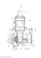
[0013] As Figuras 1 e 2 mostram, cada uma, uma bomba 10 em uma vista explodida. A bomba 10 compreende uma unidade de montagem de eixo 12 a qual suporta um eixo 14. Preso à unidade de montagem de eixo 12 está um alojamento de bomba 16 que tem um primeiro componente de alojamento axial 18, um componente de alojamento anular central 20 e um segundo componente de alojamento axial 22.[0013] Figures 1 and 2 each show a
[0014] Localizado entre o primeiro componente de alojamento axial 18 e a unidade de montagem de eixo 12 está um elemento de vedação 24.[0014] Located between the first
[0015] O eixo 14 se projeta para dentro do alojamento da bomba 16 de um modo suportado sobre um lado. Um rotor 26 compreende um cubo de rotor 28 e um anel de retenção do rotor 30 que se estende a partir do cubo de rotor 28 na direção radial e a envolve de forma ondulada. O rotor 26 é preso ao eixo 14 através de um parafuso de fixação 36. O suporte sobre um lado permite uma configuração simples do alojamento de bomba 16 uma vez que, em particular, não é necessário suportar o eixo 14 no segundo componente de alojamento axial 22.[0015] The
[0016] No texto a seguir, referências a uma direção axial se referem ao eixo de rotação do rotor 26 e referências a uma direção radial se referem a uma direção radial correspondente centralizada sobre o eixo de rotação. "Axialmente para trás" se refere à direção que aponta para a unidade de montagem de eixo 12 e "axialmente para a frente" se refere à direção que aponta para o alojamento de bomba 16. O primeiro componente de alojamento axial 18 é, assim, o componente de alojamento axialmente posterior e o segundo componente de alojamento axial 22 é, portanto, o componente de alojamento axialmente frontal.[0016] In the following text, references to an axial direction refer to the axis of rotation of
[0017] Localizada entre o rotor 26 e o primeiro componente de alojamento axial 18 está uma vedação de face mecânica 34. Em vez da vedação de face mecânica, também pode ser fornecido algum outro elemento de vedação.[0017] Located between the
[0018] A montagem do eixo 14, do elemento de vedação 24 e da vedação de face mecânica 34 e a fixação do rotor 26 ao eixo 14 também podem ser configurados de alguma outra maneira.[0018] The assembly of the
[0019] Na modalidade mostrada, o alojamento da bomba 16 é mantido unido através de quatro parafusos 38, arruelas 40 e porcas 42, em que os parafusos 38 se estendem, cada um, a partir da unidade de montagem de eixo 12 através de todos os três componentes de alojamento 18, 20, 22. No entanto, alguns outros métodos de fixação também podem ser fornecidos. Por exemplo, pode ser fornecida uma fixação independente dos componentes de alojamento 18, 20, 22 uns aos outros e do alojamento de bomba 16 à unidade de montagem de eixo 12 ou pode ser fornecida uma fixação independente do segundo componente de alojamento axial 22. Isto permite montagem e desmontagem modulares da bomba 10. Também podem ser fornecidas formas alternativas de fixação dos componentes de alojamento 18, 20, 22. Por exemplo, o componente de alojamento 18 pode ser fixado à unidade de montagem de eixo 12 e os componentes de alojamento 20 e 22 podem ser fixados ao componente de alojamento 18 através de parafusos sem cabeça no componente de alojamento 18.[0019] In the embodiment shown, the pump housing 16 is held together by means of four
[0020] O componente de alojamento anular central 20 tem um primeiro espaço de entrada/saída 44 e um segundo espaço de entrada/saída 46, cada um formado com um elemento de conexão 48 para conexão a uma tubulação.[0020] The central
[0021] Um dispositivo de bloqueio 50 compreende um elemento de bloqueio 52 e está configurado para bloquear um tubo de bomba na direção axial sobre ambos os lados do anel de retenção do rotor 30.[0021] A
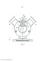
[0022] A Figura 3 mostra a bomba 10 em uma vista seccional em um plano seccional perpendicular através do eixo de rotação A do rotor 26 e do eixo 14. Os componentes de alojamento 18, 20 e 22 formam um tubo de bomba 32 em conjunto com o cubo de rotor 26, o dito tubo de bomba 32 se estendendo de forma anular em torno do cubo de rotor 26. O anel de retenção do rotor 30 divide o tubo de bomba 32 em várias câmaras de fluido 55, em que a extremidade radialmente externa do anel de retenção do rotor se une à parede radial externa, formada pelo componente de alojamento anular 18, do tubo de bomba 32 de forma vedante.[0022] Figure 3 shows the
[0023] O dispositivo de bloqueio 50 está localizado em um setor superior, na modalidade mostrada, do tubo de bomba 32. O elemento de bloqueio 52 encosta de forma vedante contra as duas faces laterais axiais do anel de retenção do rotor 30 e contra o cubo de rotor 28. Quando o rotor 26 é girado, o elemento de bloqueio 52 pode se mover na direção axial dentro de uma câmara 54 ao longo do formato ondulado do anel de retenção do rotor 30.[0023] The
[0024] A câmara 54 é formada pelo alojamento de bomba 16 e compreende uma sede a qual forma a transição entre a câmara 54 e o tubo de bomba anular 32. O elemento de bloqueio 52 encosta contra a sede da câmara 54 por meio de uma face de contato em cada posição axial e, assim, bloqueia o tubo de bomba anular 32.[0024] The
[0025] Na modalidade mostrada, o elemento de bloqueio 52 tem um canal de permuta 58 que se estende na direção axial entre uma câmara de fluido axialmente frontal e uma câmara de fluido axialmente posterior sobre o lado oposto do anel de retenção do rotor 30. O canal de permuta 58 permite, assim, que o fluido escoe na direção axial entre a câmara de fluido axialmente frontal e a câmara de fluido axialmente posterior. Deste modo, a compressão do fluido durante um movimento axial do elemento de bloqueio é evitada.[0025] In the embodiment shown, the
[0026] As Figuras secundárias (a) a (c) da Figura 4 mostram, cada uma, uma vista esquemática do tubo de bomba 32. O tubo de bomba é formado pelo próprio alojamento de bomba 16, isto é, a partir dos três componentes de alojamento 18, 20, 22. Desta forma, o espaço de instalação pode ser poupado na região do tubo de bomba 32. Além disso, a montagem e desmontagem e a limpeza da bomba 10 são simplificados.[0026] Secondary Figures (a) to (c) of Figure 4 each show a schematic view of the
[0027] A entrada e a saída do fluido a ser bombeado ocorre através de espaços de entrada/saída 44, 46 radialmente externos os quais são mostrados, cada um, por meio de linhas tracejadas na Figura 4. Na modalidade mostrada, os espaços de entrada/saída são formados de uma forma simétrica um ao outro, de modo a permitir a operação bidirecional da bomba 10.[0027] The entry and exit of the fluid to be pumped occurs through radially external inlet/
[0028] O tubo de bomba 32 é formado de modo anular e se estende com uma seção transversal constante do primeiro espaço de entrada/saída 44 radialmente externo para o segundo espaço de entrada/saída radialmente externo 46. O dispositivo de bloqueio 50 está entre os dois espaços de entrada/saída 44, 46 no tubo de bomba anular 32 e evita que um refluxo de fluido seja bombeado contra a direção de operação da bomba. Na região dos espaços de entrada/saída 44, 46 radialmente externos, o fluido a ser bombeado pode escoar na direção radial para as câmaras de fluido 55 formadas pelo rotor 26 e o alojamento de bomba. Quando o rotor 26 é girado, as câmaras de fluido são movidas ainda mais ao longo do tubo de bomba anular 32, em que uma respectiva câmara de fluido 56 fecha e permite o transporte de fluido na direção de bombeamento. Sobre o lado de saída da bomba 10, as câmaras de fluido se movem para a região do dispositivo de bloqueio 50, o que bloqueia o tubo de bomba 32, com o resultado de que o fluido a ser bombeado escoa na direção radial para fora das câmaras de fluido e para dentro do espaço de entrada/saída radialmente externo no lado da saída.[0028] The
[0029] A bomba 10 é, portanto, uma bomba de deslocamento positivo que transporta um volume fixo encerrado na câmara de fluido fechada 56.[0029] The
[0030] A função do dispositivo de bloqueio 50 é explicada no texto a seguir. O dispositivo de bloqueio 50 está localizado entre o primeiro espaço de entrada/saída 44 e o segundo espaço de entrada/saída 46 e compreende o elemento de bloqueio 52 que bloqueia o tubo de bomba 32 na direção axial sobre ambos os lados do anel de retenção do rotor 30.[0030] The function of
[0031] O dispositivo de bloqueio 50 está configurado para operação bidirecional da bomba 10. Para esta finalidade, o dispositivo de bloqueio 50 tem uma primeira sede 60 para o elemento de bloqueio 52 sobre o lado do primeiro espaço de entrada/saída 44 contra a qual o elemento de bloqueio encosta por meio de uma primeira face de contato 62 em uma primeira direção de operação para bombeamento do primeiro espaço de entrada/saída 44 para o segundo espaço de entrada/saída 46; vide Figuras 4 (a) e (b).[0031] The
[0032] O dispositivo de bloqueio também tem uma segunda sede 64 para o elemento de bloqueio 52 sobre o lado do segundo espaço de entrada/saída 46, contra a qual o elemento de bloqueio 52 encosta por meio de uma segunda face de contato em uma segunda direção de operação para bombeamento do segundo espaço de entrada/saída 46 para o primeiro espaço de entrada/saída; vide Figura 4 (c).[0032] The locking device also has a
[0033] O espaçamento entre a primeira sede 60 e a segunda sede 64 na direção circunferencial é maior do que o espaçamento entre a primeira face de contato 62 e a segunda face de contato 66 na direção circunferencial.[0033] The spacing between the
[0034] Quando a direção de operação da bomba bidirecional 10 é alterada, o elemento de bloqueio 52 se move da primeira sede 60 para a segunda sede 64, de modo que o elemento de bloqueio 52 encosta contra uma sede 60, 64, em cada caso por meio de uma face de contato 62, 66, e as respectivas faces de contato 66, 62 são afastadas do alojamento de bomba 16. Assim, é permitido um movimento de baixo atrito do elemento de bloqueio 52. Além disso, a resistência no fluido a ser bombeado é reduzida e, assim, a força de pressão do elemento de bloqueio para o rotor é reduzida, com o resultado de que as forças de atrito e, assim, também o desgaste, do elemento de bloqueio 52 são reduzidos.[0034] When the direction of operation of the
[0035] Conforme pode ser visto claramente nas Figuras 4 (a) e (b), o volume na câmara 54 muda quando o rotor 26 é girado (da direita para a esquerda no desenho) em função do formato ondulado do anel de retenção do rotor e do elemento de bloqueio 52 que se move na direção axial. Uma vez que o dispositivo de bloqueio 50 está localizado entre os dois espaços de entrada/saída 44, 46, pelo menos algumas vezes é possível que uma porção axial da câmara 54 do dispositivo de bloqueio 50 não esteja conectada ao espaço de saída 44, 46 associado.[0035] As can be clearly seen in Figures 4 (a) and (b), the volume in the
[0036] Para permitir que esta alteração de volume seja compensada, é formado um canal de permuta 58 entre a câmara de fluido axialmente frontal e a câmara de fluido axialmente posterior. Um fluxo de fluido é mostrado na direção axial pela seta na Figura 4 (b).[0036] To allow this volume change to be compensated for, an
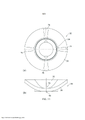
[0037] A Figura 5 mostra uma vista seccional através do componente de alojamento central 20 de acordo com o plano seccional V-V na Figura 3. O componente de alojamento 20 está localizado de modo que o dispositivo de bloqueio 50 com a câmara 54 esteja posicionado de uma maneira girada em 90° comparado com a modalidade ilustrada na Figura 3, isto é, sobre o eixo central horizontal do tubo de bomba anular 32. De preferência, a bomba 10 é formada de modo que o alojamento de bomba 16 possa ser preso à unidade de montagem de eixo 12 em diferentes ângulos.[0037] Figure 5 shows a sectional view through the
[0038] Os espaços de entrada/saída 44, 46 são formados de forma radialmente externa sobre o tubo de bomba anular 32, em que uma primeira parte dos espaços de entrada/saída 44, 46 é formada sobre toda a altura axial do tubo de bomba pelo fato de que o componente de alojamento central 20 está afastado do tubo de bomba 32 na direção radial na região dos espaços de entrada/saída 44, 46. Na modalidade mostrada, o espaçamento radial do componente de alojamento 20 estreita na direção circunferencial na respectiva região terminal do espaços de entrada/saída 44, 46, de modo que a primeira parte dos espaços de entrada/saída 44, 46 é aproximadamente triangular em vista axial. Uma segunda parte dos espaços de entrada/saída 44, 46 é formada no componente de alojamento 20 e forma uma transição para os elementos de conexão 48.[0038] The inlet/
[0039] Os espaços de entrada/saída 44, 46 são formados no quadrante superior esquerdo e no quadrante inferior esquerdo no componente de alojamento 20 na modalidade mostrada e cada um se estende até o eixo central vertical do tubo de bomba anular 32. Isto permite o esvaziamento de resíduos da bomba.[0039] The inlet/
[0040] A Figura 6 mostra uma vista seccional através do componente de alojamento central 20 de acordo com a modalidade alternativa. A modalidade difere da modalidade ilustrada na Figura 5 pelo fato de que o componente de alojamento 20 não está afastado do tubo de bomba 32 na direção radial na região dos espaços de entrada/saída 44, 46.[0040] Figure 6 shows a sectional view through the
[0041] A Figura 7 mostra uma vista seccional da bomba da Figura 3 no plano seccional VII-VII através da câmara 54 do dispositivo de bloqueio. A câmara 54 tem quatro paredes internas.[0041] Figure 7 shows a sectional view of the pump of Figure 3 in sectional plane VII-VII through
[0042] Uma parede radialmente interna da câmara 54 é formada no formato de um arco circular em torno do eixo de rotação do rotor 26 axialmente sobre ambos os lados do rotor 26 e tem o mesmo raio ou um raio ligeiramente menor do que o cubo de rotor 28 para assegurar um bom ajuste do elemento de bloqueio 52 no cubo de rotor 28.[0042] A radially inner wall of the
[0043] Uma parede radialmente externa da câmara 54 tem um perfil que está, por exemplo, no formato de um arco circular em torno do eixo de rotação do rotor 26. Também é possível que a parede radialmente externa da câmara 54 tenha algum outro perfil e seja formado, por exemplo, de modo a estar afastado do elemento de bloqueio 52, de maneira que o fluido a ser bombeado sobre o lado da pressão possa passar entre a parede radialmente externa da câmara 54 e o elemento de bloqueio 52 e, assim, comprimir o elemento de bloqueio 52 contra o cubo de rotor 26.[0043] A radially outer wall of the
[0044] Na direção circunferencial, a câmara 54 é formada por duas paredes planas que estão localizadas na direção circunferencial e cada uma envolve o tubo de fluxo de uma maneira em U e forma as primeira e segunda sedes 60, 64 para o elemento de bloqueio 52.[0044] In the circumferential direction, the
[0045] Na modalidade mostrada, o elemento de bloqueio 52 é formado com faces de contato 62, 66 que se estendem de forma paralela e estão afastadas uma da outra por uma espessura D do elemento de bloqueio 52. As duas paredes planas que estão localizadas na direção circunferencial são formadas, nesta modalidade, de modo que o elemento de bloqueio 52 possa ser deslocado através de um ângulo Y na direção circunferencial dentro da câmara 54 entre as primeira e segunda sedes 60, 64. Na modalidade mostrada, o ângulo Y é de cerca de 10°. O ângulo y pode estar em uma faixa a partir de 5° a 40°, em que o ângulo está, de preferência, em uma faixa a partir de 5° a 20°.[0045] In the embodiment shown, the locking
[0046] Para esta finalidade, as duas paredes planas que estão localizadas na direção circunferencial estão na direção radial em relação a um ponto central o qual é deslocado sobre um eixo central da bomba pela distância L, em que L = (D/2)/sin(y/2). Deste modo, a linha central do elemento de bloqueio 52 é, em cada caso, orientada na direção radial em relação ao eixo de rotação A quando o elemento de bloqueio encosta, respectivamente, contra as primeira ou segunda sedes 60, 64 através de suas faces de contato 62, 66. As primeira e segunda sedes são, assim, cada uma, formadas em planos os quais estão orientados no ângulo y uma para a outra.[0046] For this purpose, the two flat walls that are located in the circumferential direction are in the radial direction with respect to a central point which is displaced on a central axis of the pump by the distance L, where L = (D/2) /sin(y/2). In this way, the centerline of the locking
[0047] Alternativamente, é possível que o elemento de bloqueio 52 seja formado de modo que as primeira e segunda faces de contato 62, 66 estejam posicionadas em um ângulo e cada uma se estenda na direção radial do rotor 26. Neste caso, as duas paredes planas da câmara 54 que estão localizadas na direção circunferencial estão, da mesma forma, localizadas na direção radial do rotor 26. As primeira e segunda sedes são, assim, cada uma, formadas em planos os quais estão orientados no ângulo Y uma para a outra.[0047] Alternatively, it is possible that the locking
[0048] Também é possível que as duas paredes que estão localizadas na direção circunferencial e as faces de contato 62, 66 do elemento de bloqueio 52 tenham um formato geralmente cilíndrico, em particular um formato curvado, coordenadas uma com a outra.[0048] It is also possible that the two walls that are located in the circumferential direction and the contact faces 62, 66 of the locking
[0049] Os formatos das duas paredes que estão localizadas na direção circunferencial e das faces de contato 62, 66 do elemento de bloqueio 52 podem ser selecionados de modo que o elemento de bloqueio seja comprimido contra o cubo de rotor 26 pela diferença de pressão quando a bomba está em operação, por exemplo, por um formato de cunha ou formato arqueado do elemento de bloqueio 52.[0049] The shapes of the two walls that are located in the circumferential direction and the contact faces 62, 66 of the locking
[0050] Para compensar uma mudança de volume em função do movimento axial do anel de retenção do rotor 30 e do elemento de bloqueio 52, são formados dois canais de permuta 58 no dispositivo de bloqueio 50. Estes permitem que um fluxo de fluido seja bombeado entre a câmara de fluido axialmente frontal e a câmara de fluido axialmente posterior dentro do dispositivo de bloqueio. Isto permite uma configuração compacta do dispositivo de bloqueio 50, uma vez que a câmara 54 do dispositivo de bloqueio não precisa estar conectada a um dos espaços de entrada/saída 44, 46.[0050] To compensate for a change in volume due to the axial movement of the
[0051] Na câmara 54, a proporção da área seccional transversal de fluxo axial dos canais de permuta 58 para a área de projeção axial do anel de retenção do rotor 30 e daquela parte do elemento de bloqueio 52 que se projeta além do anel de retenção do rotor é, de preferência, pelo menos 0,2 e está, de preferência, na faixa a partir de 0,2 a 0,6. Isto permite uma compensação suficiente de volume com uma construção compacta do dispositivo de bloqueio 50.[0051] In the
[0052] As Figuras secundárias (a) a (f) da Figura 8 mostram várias vistas detalhadas do elemento de bloqueio 52 da modalidade mostrada na Figura 7. A Figura secundária (a) mostra uma vista em perspectiva do elemento de bloqueio 52. A Figura secundária (b) mostra uma vista seccional no plano central. A figura secundária (c) mostra uma vista na direção radial do cubo de rotor 26 para fora. A Figura secundária (d) mostra uma vista na direção circunferencial com uma face de contato 62, 66. A Figura secundária (e) mostra uma vista na direção radial para dentro em direção ao cubo de rotor 26 e a Figura secundária (f) mostra uma vista do elemento de bloqueio 52 na direção axial.[0052] Secondary Figures (a) to (f) of Figure 8 show several detailed views of the locking
[0053] O elemento de bloqueio 52 é formado de forma simétrica em espelho no plano central que se estende na direção axial e na direção radial. Como um resultado da configuração simétrica do elemento de bloqueio 52, não é necessário respeitar uma orientação particular do elemento de bloqueio quando a bomba é montada e, como um resultado, a montagem da bomba pode ser simplificada e avarias são evitadas.[0053] The locking
[0054] Além das primeira e segunda faces de contato 62, 66 que encostam contra as primeira e segunda sedes 60, 64 formadas no alojamento de bomba 16, o elemento de bloqueio 52 tem duas faces de contato de rotor-cubo radialmente internas 68 e faces de vedação de rotor-anel de retenção 70, cada uma localizada sobre ambos os lados de uma ranhura 72 para receber o anel de retenção do rotor 30 e pelas quais o elemento de bloqueio 52 encosta contra o cubo de rotor 28 e o anel de retenção do rotor 30 de maneira vedante.[0054] In addition to the first and second contact faces 62, 66 that abut against the first and
[0055] O canal de permuta 58 é formado entre a primeira face de contato 62 e a segunda face de contato 66. Na modalidade mostrada, o canal de permuta 58 do elemento de bloqueio 52 é configurado como uma ranhura a qual se estende na direção axial ao longo de todo o elemento de bloqueio 52 sobre aquele lado do elemento de bloqueio que está distante do cubo de rotor. A fim de melhorar o fluxo do fluido a ser bombeado através do canal de permuta 58, a ranhura se estende aproximadamente em toda a altura do elemento de bloqueio nas duas extremidades axiais e estreita em direção à região central do elemento de bloqueio, na qual a ranhura 72 está localizada.[0055] The
[0056] A Figura 9 mostra uma segunda modalidade da invenção, em que a bomba 10 difere da primeira modalidade ilustrada na Figura 7 apenas pelo elemento de bloqueio 52. O elemento de bloqueio 52 é formado sem a ranhura central. Nesta modalidade, o elemento de bloqueio 52 está afastado da parede radialmente externa na câmara 54, de modo que o fluido a ser bombeado comprime o elemento de bloqueio 52 contra o cubo de rotor 28. De forma análoga à primeira modalidade, o elemento de bloqueio da segunda modalidade também pode ter uma geometria diferente.[0056] Figure 9 shows a second embodiment of the invention, in which the
[0057] A Figura 10 mostra o elemento de bloqueio da segunda modalidade, em que a Figura secundária (a) mostra uma vista em perspectiva do elemento de bloqueio 52 e a Figura secundária (b) mostra uma vista lateral do elemento de bloqueio 52. De maneira análoga ao elemento de bloqueio da Figura 8, o elemento de bloqueio 52 tem uma primeira e uma segunda face de contato 62, 66 que encostam contra as primeira e segunda sedes 60, 64 formadas no alojamento de bomba 16 e duas faces de contato de rotor-cubo radialmente internas 68 e faces de vedação de rotor-anel de retenção 70, cada uma localizada sobre ambos os lados de uma ranhura 72 para receber o anel de retenção do rotor 30 e pelas quais o elemento de bloqueio 52 encosta contra o cubo de rotor 28 e o anel de retenção do rotor 30 de forma vedante.[0057] Figure 10 shows the locking element of the second embodiment, in which the secondary Figure (a) shows a perspective view of the locking
[0058] No lado radial externo do elemento de bloqueio 52, o elemento de bloqueio 52 tem duas faces inclinadas 74. No caso de um movimento na direção axial, o elemento de bloqueio 52 é comprimido contra o cubo de rotor 28 pelas faces inclinadas 74 e a resistência do fluido a ser bombeado.[0058] On the outer radial side of the locking
[0059] As Figuras secundárias (a) e (b) da Figura 11 mostram, cada uma, uma vista do rotor 26, em que a Figura secundária (a) mostra uma vista plana axial do rotor 26 e a Figura secundária (b) mostra uma vista plana radial do rotor 26.[0059] The secondary Figures (a) and (b) of Figure 11 each show a view of the
[0060] O anel de retenção do rotor 30 se estende na direção radial do cubo de rotor 28 e envolve o cubo de rotor 28 de uma forma ondulada. Na modalidade mostrada, o anel de retenção do rotor 30 está, nas duas posições extremas axiais, em dois pontos opostos cada. Assim, o anel de retenção do rotor forma duas câmaras de fluido em cada um dos dois lados axiais do anel de retenção do rotor.[0060] The
[0061] Na modalidade mostrada, o anel de retenção do rotor 30 se estende de forma achatada nas posições extremas axiais 76, com o resultado de que a vedação é aprimorada nas faces terminais axiais do tubo de bomba 32 as quais são formadas pelos dois componentes de alojamento axial 18 e 22. Isto permite, em particular, uma ampliação de um espaço entre o anel de retenção do rotor 30 e as faces terminais axiais do tubo de bomba 32. Isto permite que a bomba gere maiores pressões com maiores dimensões de espaço.[0061] In the embodiment shown, the
[0062] Na modalidade mostrada, o rotor 26 é produzido a partir de uma liga antiaderência.[0062] In the embodiment shown, the
[0063] De preferência, é fornecida uma face de vedação, na forma de uma ranhura circunferencial, para uma vedação de face mecânica no cubo de rotor 26.[0063] Preferably, a sealing face is provided, in the form of a circumferential groove, for a mechanical face seal on the
[0064] Também é possível usar outros formatos de rotor para a bomba.[0064] It is also possible to use other rotor formats for the pump.
[0065] Na modalidade mostrada, a bomba 10 é formada com um dispositivo de bloqueio 50 que permite que a bomba 10 seja operada sobre ambos os lados. No entanto, também pode ser fornecido algum outro dispositivo de bloqueio 50 que permita que a bomba seja operada, por exemplo, a partir de um lado.[0065] In the embodiment shown, the
Claims (10)
Applications Claiming Priority (3)
| Application Number | Priority Date | Filing Date | Title |
|---|---|---|---|
| DE102015116768.9A DE102015116768A1 (en) | 2015-10-02 | 2015-10-02 | pump |
| DE102015116768.9 | 2015-10-02 | ||
| PCT/EP2016/073337 WO2017055497A1 (en) | 2015-10-02 | 2016-09-29 | Pump with axially movable vane |
Publications (2)
| Publication Number | Publication Date |
|---|---|
| BR112018003554A2 BR112018003554A2 (en) | 2018-09-25 |
| BR112018003554B1 true BR112018003554B1 (en) | 2022-12-27 |
Family
ID=57103997
Family Applications (1)
| Application Number | Title | Priority Date | Filing Date |
|---|---|---|---|
| BR112018003554-8A BR112018003554B1 (en) | 2015-10-02 | 2016-09-29 | BOMB |
Country Status (10)
| Country | Link |
|---|---|
| US (1) | US11098713B2 (en) |
| EP (1) | EP3356649B1 (en) |
| JP (1) | JP6722276B2 (en) |
| CN (1) | CN108138573B (en) |
| BR (1) | BR112018003554B1 (en) |
| DE (1) | DE102015116768A1 (en) |
| DK (1) | DK3356649T3 (en) |
| ES (1) | ES2887601T3 (en) |
| PT (1) | PT3356649T (en) |
| WO (1) | WO2017055497A1 (en) |
Families Citing this family (6)
| Publication number | Priority date | Publication date | Assignee | Title |
|---|---|---|---|---|
| DE102015116770A1 (en) * | 2015-10-02 | 2017-04-06 | Watson-Marlow Gmbh | Pump and locking device |
| EP3483440B1 (en) | 2017-11-08 | 2020-05-27 | Oina VV AB | Peristaltic pump |
| CN107956688B (en) * | 2017-12-13 | 2024-04-16 | 杭州电子科技大学 | Axial end face seal rotor molded line displacement pump |
| CN108561307B (en) * | 2017-12-13 | 2024-04-12 | 杭州电子科技大学 | Bilateral symmetry plane distortion vane deflection pump |
| EP3827172A1 (en) | 2018-07-23 | 2021-06-02 | Revotory | Volumetric pump with flow complementary radial cams |
| CN110425078A (en) * | 2019-06-21 | 2019-11-08 | 中国计量大学上虞高等研究院有限公司 | A kind of left-right balance motor |
Family Cites Families (20)
| Publication number | Priority date | Publication date | Assignee | Title |
|---|---|---|---|---|
| GB189913992A (en) * | 1899-07-06 | 1900-02-10 | ||
| US1690727A (en) | 1925-02-13 | 1928-11-06 | Joseph F Jaworowski | Rotary pump |
| US1690728A (en) * | 1927-06-16 | 1928-11-06 | Joseph F Jaworowski | Rotary pump |
| US3156158A (en) * | 1959-08-20 | 1964-11-10 | James B Pamplin | Rotary fluid displacement apparatus |
| JPS519925B1 (en) * | 1970-01-31 | 1976-03-31 | ||
| JPS519925A (en) | 1974-06-28 | 1976-01-27 | Yukio Yoshihara | HONNOPEEJINOAIDANOMIZONIKAMIRUIOHASAMIKOMUKIGU |
| US3994638A (en) * | 1974-08-29 | 1976-11-30 | Frick Company | Oscillating rotary compressor |
| JPS5169206A (en) | 1974-12-13 | 1976-06-15 | Nippon Piston Ring Co Ltd | KAITENSHIKIRYUTAIHONPU |
| US4093408A (en) * | 1976-12-03 | 1978-06-06 | Yoshichika Yamaguchi | Positive cam type compressor |
| JPS553557A (en) | 1978-06-22 | 1980-01-11 | Eiwa Kogyo Kk | Three-way damper |
| US5980225A (en) * | 1996-07-05 | 1999-11-09 | Sundstrand Fluid Handling Corporation | Rotary pump having a drive shaft releasably connected to the rotor |
| AU2002365785A1 (en) * | 2001-12-03 | 2003-06-17 | Lg Electronics Inc. | Discharging part structure for compressor |
| EP1633982A1 (en) * | 2003-06-13 | 2006-03-15 | Kyung-Yul Hyun | Fluid pump and motor |
| WO2005066500A1 (en) * | 2004-01-09 | 2005-07-21 | Manfred Sommer | Rotary piston pump having an axially moving vane |
| EP1637740A1 (en) * | 2004-09-20 | 2006-03-22 | Sundyne Corporation | Rotary displacement pump comprising scraper and guide of the scraper |
| EP1637739A1 (en) * | 2004-09-20 | 2006-03-22 | Maso Process-Pumpen GmbH | Vane pump comprising a two-part stator |
| JP2006144592A (en) | 2004-11-17 | 2006-06-08 | Primix Copr | Rotary pump |
| JP2008082218A (en) * | 2006-09-27 | 2008-04-10 | Primix Copr | Rotary pump |
| WO2012034592A1 (en) * | 2010-09-15 | 2012-03-22 | Watson-Marlow Gmbh | Rotary displacement pump for pumping solids emulsions, especially liquid explosives |
| EP2565454B1 (en) | 2011-09-02 | 2016-12-14 | Watson Marlow GmbH MasoSine | Rotary displacement pump for pumping flowable materials of high viscosity |
-
2015
- 2015-10-02 DE DE102015116768.9A patent/DE102015116768A1/en not_active Ceased
-
2016
- 2016-09-29 WO PCT/EP2016/073337 patent/WO2017055497A1/en active Application Filing
- 2016-09-29 ES ES16777965T patent/ES2887601T3/en active Active
- 2016-09-29 JP JP2018510455A patent/JP6722276B2/en active Active
- 2016-09-29 BR BR112018003554-8A patent/BR112018003554B1/en active IP Right Grant
- 2016-09-29 US US15/763,426 patent/US11098713B2/en active Active
- 2016-09-29 PT PT167779651T patent/PT3356649T/en unknown
- 2016-09-29 CN CN201680055624.0A patent/CN108138573B/en active Active
- 2016-09-29 EP EP16777965.1A patent/EP3356649B1/en active Active
- 2016-09-29 DK DK16777965.1T patent/DK3356649T3/en active
Also Published As
| Publication number | Publication date |
|---|---|
| WO2017055497A1 (en) | 2017-04-06 |
| PT3356649T (en) | 2021-09-15 |
| EP3356649A1 (en) | 2018-08-08 |
| BR112018003554A2 (en) | 2018-09-25 |
| ES2887601T3 (en) | 2021-12-23 |
| DK3356649T3 (en) | 2021-09-20 |
| EP3356649B1 (en) | 2021-06-30 |
| JP6722276B2 (en) | 2020-07-15 |
| US20180306183A1 (en) | 2018-10-25 |
| JP2018529874A (en) | 2018-10-11 |
| CN108138573B (en) | 2021-03-19 |
| CN108138573A (en) | 2018-06-08 |
| US11098713B2 (en) | 2021-08-24 |
| DE102015116768A1 (en) | 2017-04-20 |
Similar Documents
| Publication | Publication Date | Title |
|---|---|---|
| BR112018003554B1 (en) | BOMB | |
| BR112018003966B1 (en) | PUMP AND LOCKING ELEMENT | |
| GB2410988A (en) | A mechanical seal for sealing between a rotary shaft and a housing | |
| US9885356B2 (en) | Variable displacement pump | |
| CN103154519A (en) | Rotary displacement pump for pumping solids emulsions, especially liquid explosives | |
| BR112018003620B1 (en) | PUMP AND LOCKING DEVICE | |
| EP2894294B1 (en) | Control ring for a hydrostatical device | |
| US1271585A (en) | Rotary pump. | |
| US8985979B2 (en) | Positive displacement rotary machine | |
| US3218983A (en) | Flexible-vaned pump with liner cam | |
| US10655624B2 (en) | Vane pump device for controlling deviation of a force applied to the vanes | |
| US10371138B2 (en) | Rotary pump |
Legal Events
| Date | Code | Title | Description |
|---|---|---|---|
| B06U | Preliminary requirement: requests with searches performed by other patent offices: procedure suspended [chapter 6.21 patent gazette] | ||
| B09A | Decision: intention to grant [chapter 9.1 patent gazette] | ||
| B16A | Patent or certificate of addition of invention granted [chapter 16.1 patent gazette] |
Free format text: PRAZO DE VALIDADE: 20 (VINTE) ANOS CONTADOS A PARTIR DE 29/09/2016, OBSERVADAS AS CONDICOES LEGAIS |