BR112017027922B1 - SURGICAL INSTRUMENT - Google Patents
SURGICAL INSTRUMENT Download PDFInfo
- Publication number
- BR112017027922B1 BR112017027922B1 BR112017027922-3A BR112017027922A BR112017027922B1 BR 112017027922 B1 BR112017027922 B1 BR 112017027922B1 BR 112017027922 A BR112017027922 A BR 112017027922A BR 112017027922 B1 BR112017027922 B1 BR 112017027922B1
- Authority
- BR
- Brazil
- Prior art keywords
- anvil
- assembly
- rescue
- trocar
- instrument
- Prior art date
Links
Images


Classifications
-
- A—HUMAN NECESSITIES
- A61—MEDICAL OR VETERINARY SCIENCE; HYGIENE
- A61B—DIAGNOSIS; SURGERY; IDENTIFICATION
- A61B17/00—Surgical instruments, devices or methods, e.g. tourniquets
- A61B17/068—Surgical staplers, e.g. containing multiple staples or clamps
-
- A—HUMAN NECESSITIES
- A61—MEDICAL OR VETERINARY SCIENCE; HYGIENE
- A61B—DIAGNOSIS; SURGERY; IDENTIFICATION
- A61B17/00—Surgical instruments, devices or methods, e.g. tourniquets
- A61B17/11—Surgical instruments, devices or methods, e.g. tourniquets for performing anastomosis; Buttons for anastomosis
- A61B17/1114—Surgical instruments, devices or methods, e.g. tourniquets for performing anastomosis; Buttons for anastomosis of the digestive tract, e.g. bowels or oesophagus
-
- A—HUMAN NECESSITIES
- A61—MEDICAL OR VETERINARY SCIENCE; HYGIENE
- A61B—DIAGNOSIS; SURGERY; IDENTIFICATION
- A61B17/00—Surgical instruments, devices or methods, e.g. tourniquets
- A61B17/11—Surgical instruments, devices or methods, e.g. tourniquets for performing anastomosis; Buttons for anastomosis
- A61B17/115—Staplers for performing anastomosis in a single operation
- A61B17/1155—Circular staplers comprising a plurality of staples
-
- A—HUMAN NECESSITIES
- A61—MEDICAL OR VETERINARY SCIENCE; HYGIENE
- A61B—DIAGNOSIS; SURGERY; IDENTIFICATION
- A61B17/00—Surgical instruments, devices or methods, e.g. tourniquets
- A61B17/10—Surgical instruments, devices or methods, e.g. tourniquets for applying or removing wound clamps, e.g. containing only one clamp or staple; Wound clamp magazines
- A61B17/105—Wound clamp magazines
-
- A—HUMAN NECESSITIES
- A61—MEDICAL OR VETERINARY SCIENCE; HYGIENE
- A61B—DIAGNOSIS; SURGERY; IDENTIFICATION
- A61B17/00—Surgical instruments, devices or methods, e.g. tourniquets
- A61B17/068—Surgical staplers, e.g. containing multiple staples or clamps
- A61B17/072—Surgical staplers, e.g. containing multiple staples or clamps for applying a row of staples in a single action, e.g. the staples being applied simultaneously
- A61B17/07207—Surgical staplers, e.g. containing multiple staples or clamps for applying a row of staples in a single action, e.g. the staples being applied simultaneously the staples being applied sequentially
-
- A—HUMAN NECESSITIES
- A61—MEDICAL OR VETERINARY SCIENCE; HYGIENE
- A61B—DIAGNOSIS; SURGERY; IDENTIFICATION
- A61B17/00—Surgical instruments, devices or methods, e.g. tourniquets
- A61B2017/00367—Details of actuation of instruments, e.g. relations between pushing buttons, or the like, and activation of the tool, working tip, or the like
- A61B2017/00398—Details of actuation of instruments, e.g. relations between pushing buttons, or the like, and activation of the tool, working tip, or the like using powered actuators, e.g. stepper motors, solenoids
-
- A—HUMAN NECESSITIES
- A61—MEDICAL OR VETERINARY SCIENCE; HYGIENE
- A61B—DIAGNOSIS; SURGERY; IDENTIFICATION
- A61B17/00—Surgical instruments, devices or methods, e.g. tourniquets
- A61B17/068—Surgical staplers, e.g. containing multiple staples or clamps
- A61B17/072—Surgical staplers, e.g. containing multiple staples or clamps for applying a row of staples in a single action, e.g. the staples being applied simultaneously
- A61B2017/07214—Stapler heads
-
- A—HUMAN NECESSITIES
- A61—MEDICAL OR VETERINARY SCIENCE; HYGIENE
- A61B—DIAGNOSIS; SURGERY; IDENTIFICATION
- A61B17/00—Surgical instruments, devices or methods, e.g. tourniquets
- A61B17/11—Surgical instruments, devices or methods, e.g. tourniquets for performing anastomosis; Buttons for anastomosis
- A61B2017/1132—End-to-end connections
-
- A—HUMAN NECESSITIES
- A61—MEDICAL OR VETERINARY SCIENCE; HYGIENE
- A61B—DIAGNOSIS; SURGERY; IDENTIFICATION
- A61B90/00—Instruments, implements or accessories specially adapted for surgery or diagnosis and not covered by any of the groups A61B1/00 - A61B50/00, e.g. for luxation treatment or for protecting wound edges
- A61B90/08—Accessories or related features not otherwise provided for
- A61B2090/0801—Prevention of accidental cutting or pricking
- A61B2090/08021—Prevention of accidental cutting or pricking of the patient or his organs
Abstract
CONJUNTO DE RESGATE PARA GRAMPEADOR CIRÚRGICO. Trata-se de um instrumento cirúrgico que inclui uma bigorna, um conjunto de aplicação de grampos, um membro de ajuste, um recurso de entrada de usuário, e um conjunto de resgate. O conjunto de aplicação de grampo inclui uma superfície distal que define aberturas, e um acionador que é operável para acionar uma matriz anular de grampos através das aberturas da superfície distal e para dentro do tecido. O membro de ajuste é operável para ajustar a posição da bigorna de modo a variar uma distância de vão definido entre a bigorna e a superfície distal. O elemento de ajuste inclui uma primeira seção e uma segunda seção. O recurso de entrada do usuário é operável para atuar o acionador para, desse modo, acionar os grampos. O conjunto de resgate é operável para separar seletivamente a primeira seção do membro de ajuste da segunda seção do membro de ajuste.SURGICAL STAPLER RESCUE SET. It is a surgical instrument that includes an anvil, a stapling set, an adjustment member, a user input feature, and a rescue set. The staple delivery assembly includes a distal surface defining apertures, and an actuator that is operable to drive an annular array of staples through apertures in the distal surface and into the tissue. The adjusting member is operable to adjust the position of the anvil to vary a defined gap distance between the anvil and the distal surface. The fit element includes a first section and a second section. The user input facility is operable to actuate the trigger to thereby actuate the clamps. The rescue assembly is operable to selectively separate the first section of the adjustment member from the second section of the adjustment member.
Description
[001] Em alguns procedimentos cirúrgicos (por exemplo, procedimentos colorretais, bariátricos, torácicos, etc.), porções do trato digestivo de um paciente (ex., trato gastrointestinal e/ou esôfago, etc.) podem ser cortadas e removidas para eliminar tecido indesejado ou por outras razões. Uma vez que o tecido é removido, as porções restantes do trato digestivo podem ser acopladas em uma anastomose de ponta a ponta. A anastomose de ponta a ponta pode fornecer uma trajetória de fluxo substancialmente desobstruída de uma porção do trato digestivo para a outra porção do trato digestivo, sem fornecer também qualquer tipo de vazamento no local da anastomose.[001] In some surgical procedures (eg, colorectal, bariatric, thoracic procedures, etc.), portions of a patient's digestive tract (eg, gastrointestinal tract and/or esophagus, etc.) may be cut and removed to eliminate unwanted tissue or for other reasons. Once the tissue is removed, the remaining portions of the digestive tract can be joined together in an end-to-end anastomosis. The end-to-end anastomosis can provide a substantially unobstructed flow path from one portion of the digestive tract to the other portion of the digestive tract, without also providing any type of leakage at the site of the anastomosis.
[002] Um exemplo de um instrumento que pode ser usado para proporcionar uma anastomose de ponta a ponta é um grampeador circular. Alguns desses grampeadores funcionam de modo a prender camadas de tecido, cortar através das camadas de tecido presas e fazer com que os grampos atravessem as camadas grampeadas de tecido para selar substancialmente as camadas perto das extremidades separadas das camadas de tecido, unindo, assim, as duas extremidades separadas do lúmen anatômico. O grampeador circular pode ser configurado para separar e selar o tecido de modo substancialmente simultâneo. Por exemplo, o grampeador circular pode separar o tecido em excesso, que está na parte interna de uma matriz anular de grampos em uma anastomose, para proporcionar uma transição substancialmente suave entre as seções de lúmen anatômicas que são unidas na anastomose. Grampeadores circulares podem ser usados em procedimentos abertos ou em procedimentos endoscópicos. Em alguns casos, uma porção do grampeador circular é inserida através de um orifício de ocorrência natural do paciente.[002] An example of an instrument that can be used to provide an end-to-end anastomosis is a circular stapler. Some of these staplers function to clamp layers of fabric, cut through the trapped fabric layers, and cause the staples to pass through the stapled layers of fabric to substantially seal the layers near the separated ends of the fabric layers, thereby joining the fabric layers together. two separate ends of the anatomical lumen. The circular stapler can be configured to separate and seal tissue substantially simultaneously. For example, the circular stapler can separate excess tissue that is on the inside of an annular array of staples at an anastomosis to provide a substantially smooth transition between anatomical lumen sections that are joined at the anastomosis. Circular staplers can be used in open procedures or in endoscopic procedures. In some cases, a portion of the circular stapler is inserted through a naturally occurring orifice in the patient.
[003] Exemplos de grampeadores circulares são descritos na patente US n° 5.205.459, intitulada "Surgical Anastomosis Stapling Instrument", concedida em 27 de abril de 1993; na patente US n° 5.271.544, intitulada "Surgical Anastomosis Stapling Instrument", concedida em 21 de dezembro de 1993; na patente US n° 5.275.322, intitulada "Surgical Anastomosis Stapling Instrument", concedida 4 de janeiro de 1994; na patente US n° 5.285.945, intitulada "Surgical Anastomosis Stapling Instrument", concedida em 15 de fevereiro de 1994; na patente US n° 5.292.053, intitulada "Surgical Anastomosis Stapling Instrument", concedida em 8 de março de 1994; na patente US n° 5.333.773, intitulada "Surgical Anastomosis Stapling Instrument", concedida em 2 de agosto de 1994; na patente US n° 5.350.104, intitulada "Surgical Anastomosis Stapling Instrument", concedida em 27 de setembro de 1994; na patente US n° 5.533.661, intitulada "Surgical Anastomosis Stapling Instrument", concedida em 9 de julho de 1996; e Patente US n° 8.910.847, intitulada "Low Cost Anvil Assembly for a Circular Stapler", concedida em 16 de dezembro de 2014; A descrição de cada uma das patentes US supracitadas está incorporada na presente invenção a título de referência.[003] Examples of circular staplers are described in US patent No. 5,205,459, entitled "Surgical Anastomosis Stapling Instrument", issued on April 27, 1993; in US Patent No. 5,271,544, entitled "Surgical Anastomosis Stapling Instrument", issued December 21, 1993; in US Patent No. 5,275,322, entitled "Surgical Anastomosis Stapling Instrument", issued January 4, 1994; in US Patent No. 5,285,945, entitled "Surgical Anastomosis Stapling Instrument", issued February 15, 1994; in US Patent No. 5,292,053, entitled "Surgical Anastomosis Stapling Instrument", issued March 8, 1994; in US Patent No. 5,333,773, entitled "Surgical Anastomosis Stapling Instrument", issued August 2, 1994; in US Patent No. 5,350,104, entitled "Surgical Anastomosis Stapling Instrument", issued September 27, 1994; in US Patent No. 5,533,661, entitled "Surgical Anastomosis Stapling Instrument", issued July 9, 1996; and US Patent No. 8,910,847 entitled "Low Cost Anvil Assembly for a Circular Stapler", issued December 16, 2014; The description of each of the aforementioned US patents is incorporated herein by reference.
[004] Alguns grampeadores circulares podem incluir um mecanismo de acionamento motorizado. Exemplos de grampeadores circulares com mecanismos de acionamento motorizados são descritos na Publicação de Patente US. n° 2015/0083772, intitulada "Surgical Stapler with Rotary Cam Drive and Return", publicada em 26 de março de 2015; publicação de patente n° 2015/0083773, intitulada "Surgical Stapling Instrument with Drive Assembly Having Toggle Features," publicada em 26 de março de 2015; publicação de patente n° 2015/0083774, intitulada "Control Features for Motorized Surgical Stapling Instrument", publicada em 26 de março de 2015; e na publicação US n° 2015/0083775, intitulada "Surgical Stapler with Rotary Cam Drive", publicada em 26 de março de 2015; A divulgação de cada um dos Pedidos de Patente US supracitados está incorporada na presente invenção a título de referência.[004] Some circular staplers may include a motorized drive mechanism. Examples of circular staplers with motorized drive mechanisms are described in US Patent Publication. #2015/0083772, entitled "Surgical Stapler with Rotary Cam Drive and Return", issued March 26, 2015; Patent Publication No. 2015/0083773, entitled "Surgical Stapling Instrument with Drive Assembly Having Toggle Features," published March 26, 2015; Patent Publication No. 2015/0083774 entitled "Control Features for Motorized Surgical Stapling Instrument", published March 26, 2015; and in US Publication No. 2015/0083775 entitled "Surgical Stapler with Rotary Cam Drive", published March 26, 2015; The disclosure of each of the foregoing US Patent Applications is incorporated into the present invention by reference.
[005] Apesar de vários tipos de instrumentos de grampeamento cirúrgico e componentes associados terem sido produzidos e usados, acredita-se que ninguém antes do(s) inventor(es) tenha produzido ou usado a invenção descrita nas reivindicações em anexo.[005] Although various types of surgical stapling instruments and associated components have been produced and used, it is believed that no one before the inventor(s) has produced or used the invention described in the appended claims.
[006] Embora o relatório descritivo conclua com reivindicações que especificamente indicam e distintamente reivindicam esta tecnologia, acredita-se que esta tecnologia será mais bem compreendida a partir da descrição a seguir de certos exemplos, tomada em conjunto com os desenhos anexos, nos quais números de referência iguais identificam elementos iguais, e em que:[006] Although the specification concludes with claims that specifically indicate and distinctly claim this technology, it is believed that this technology will be better understood from the following description of certain examples, taken in conjunction with the accompanying drawings, in which numbers like reference marks identify like elements, and where:
[007] Figura 1 mostra uma vista em perspectiva de um grampeador circular exemplificador;[007] Figure 1 shows a perspective view of an exemplary circular stapler;
[008] Figura 2 mostra uma vista em perspectiva do grampeador circular da Figura 1, com uma bateria removida de um conjunto de cabo e uma bigorna removida de um conjunto de cabeça de grampeamento;[008] Figure 2 shows a perspective view of the circular stapler of Figure 1, with a battery removed from a handle assembly and an anvil removed from a stapler head assembly;
[009] Figura 3 mostra uma vista em perspectiva da bigorna do grampeador circular da Figura 1;[009] Figure 3 shows a perspective view of the circular stapler anvil of Figure 1;
[0010] Figura 4 representa uma outra vista em perspectiva da bigorna da Figura 3;[0010] Figure 4 represents another perspective view of the anvil of Figure 3;
[0011] Figura 5 mostra uma vista em elevação lateral explodida da bigorna da Figura 3;[0011] Figure 5 shows an exploded side elevation view of the anvil of Figure 3;
[0012] Figura 6 mostra uma vista em perspectiva do conjunto de cabeça de grampeamento do grampeador circular da Figura 1;[0012] Figure 6 shows a perspective view of the stapling head assembly of the circular stapler of Figure 1;
[0013] Figura 7 mostra uma vista em perspectiva explodida do conjunto de cabeça de grampeamento da Figura 6;[0013] Figure 7 shows an exploded perspective view of the stapling head assembly of Figure 6;
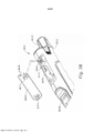
[0014] Figura 8 mostra uma vista em perspectiva explodida do grampeador circular da Figura 1, com porções do conjunto do eixo mostradas separadamente uma da outra;[0014] Figure 8 shows an exploded perspective view of the circular stapler of Figure 1, with portions of the shaft assembly shown separately from one another;
[0015] Figura 9 mostra uma vista em perspectiva do conjunto de cabo do grampeador circular da Figura 1, com um meio gabinete omitido para revelar os componentes internos do conjunto de cabo;[0015] Figure 9 shows a perspective view of the cable assembly of the circular stapler of Figure 1, with a half-enclosure omitted to reveal the internal components of the cable assembly;
[0016] Figura 10 mostra uma vista em perspectiva de um bráquete do conjunto de cabo da Figura 9;[0016] Figure 10 shows a perspective view of a bracket of the cable assembly of Figure 9;
[0017] Figura 11 mostra uma vista em perspectiva de um membro indicador do conjunto de cabo da Figura 9;[0017] Figure 11 shows a perspective view of an indicator member of the cable assembly of Figure 9;
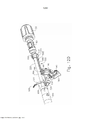
[0018] Figura 12A mostra uma vista em perspectiva de um conjunto de acionamento de bigorna do grampeador circular da Figura 1, uma haste de atuação em uma primeira posição;[0018] Figure 12A shows a perspective view of an anvil drive assembly of the circular stapler of Figure 1, an actuating rod in a first position;
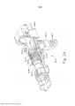
[0019] Figura 12B mostra uma vista em perspectiva do conjunto de acionamento de bigorna da Figura 12A, com a haste de atuação movida para uma segunda posição para engatar o bráquete da Figura 10;[0019] Figure 12B shows a perspective view of the anvil drive assembly of Figure 12A, with the actuation rod moved to a second position to engage the bracket of Figure 10;
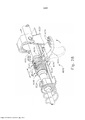
[0020] Figura 12C mostra uma vista em perspectiva do conjunto de acionamento de bigorna da Figura 12A, com a haste de atuação movida para uma terceira posição para retrair o bráquete da Figura 10 proximalmente;[0020] Figure 12C shows a perspective view of the anvil drive assembly of Figure 12A, with the actuation rod moved to a third position to retract the bracket of Figure 10 proximally;
[0021] Figura 12D mostra uma vista em perspectiva do conjunto de acionamento de bigorna da Figura 12A, com um gatilho de segurança pivotado a partir de uma primeira posição para uma segunda posição;[0021] Figure 12D shows a perspective view of the anvil drive assembly of Figure 12A, with a safety trigger pivoted from a first position to a second position;
[0022] Figura 12E mostra uma vista em perspectiva do conjunto de acionamento de bigorna da Figura 12A, com um gatilho de disparo pivotado de uma primeira posição para uma segunda posição;[0022] Figure 12E shows a perspective view of the anvil drive assembly of Figure 12A, with a firing trigger pivoted from a first position to a second position;
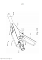
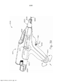
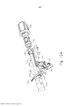
[0023] Figura 13 mostra uma vista em perspectiva de um conjunto de acionamento de cabeça de grampeamento do grampeador circular da Figura 1;[0023] Figure 13 shows a perspective view of a stapling head drive assembly of the circular stapler of Figure 1;
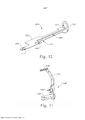
[0024] Figura 14 mostra uma vista em perspectiva de um seguidor de came do conjunto de acionamento da cabeça de grampeamento da Figura 13;[0024] Figure 14 shows a perspective view of a cam follower of the staple head drive assembly of Figure 13;
[0025] Figura 15 mostra uma outra vista em perspectiva do seguidor de came da Figura 14;[0025] Figure 15 shows another perspective view of the cam follower of Figure 14;
[0026] Figura 16 mostra uma vista em perspectiva de um came giratório do conjunto de acionamento da cabeça de grampeamento da Figura 13;[0026] Figure 16 shows a perspective view of a rotating cam of the staple head drive assembly of Figure 13;
[0027] Figura 17 mostra outra vista em perspectiva do came giratório da Figura 16;[0027] Figure 17 shows another perspective view of the rotating cam in Figure 16;
[0028] Figura 18A mostra uma vista em elevação lateral do conjunto de acionamento de cabeça de grampeamento da Figura 13, com o came giratório em uma primeira posição angular e o seguidor de came em uma primeira posição pivotante;[0028] Figure 18A shows a side elevation view of the stapling head drive assembly of Figure 13, with the rotating cam in a first angular position and the cam follower in a first pivotal position;
[0029] Figura 18B mostra uma vista em elevação lateral do conjunto de acionamento de cabeça de grampeamento da Figura 13, com o came giratório em uma segunda posição angular e o seguidor de came em uma segunda posição pivotante;[0029] Figure 18B shows a side elevation view of the stapling head drive assembly of Figure 13, with the rotating cam in a second angular position and the cam follower in a second pivotal position;
[0030] Figura 19A mostra uma vista em perspectiva do came giratório da Figura 16, um membro oscilador e uma chave de parada, com o came giratório em uma primeira posição angular e o membro oscilador em uma primeira posição pivotante;[0030] Figure 19A shows a perspective view of the rotatable cam of Figure 16, a rocker member and a stop switch, with the rocker cam in a first angular position and the rocker member in a first pivotal position;
[0031] Figura 19B mostra uma vista em perspectiva do came giratório da Figura 16, o membro oscilador da Figura 19A e a chave de parada da Figura 19A com o came giratório em uma quarta posição angular e o membro oscilador em uma segunda posição pivotante;[0031] Figure 19B shows a perspective view of the rotary cam of Figure 16, the rocker member of Figure 19A and the stop switch of Figure 19A with the rotary cam in a fourth angular position and the rocker member in a second pivotal position;
[0032] Figura 20A mostra uma vista de extremidade esquemática do came giratório da Figura 16, o seguidor de came da Figura 14 e o membro oscilador da Figura 19A com o came giratório em uma primeira posição angular e o seguidor de came na primeira posição pivotante e o membro oscilador na primeira posição pivotante;[0032] Figure 20A shows a schematic end view of the rotating cam of Figure 16, the cam follower of Figure 14 and the rocker member of Figure 19A with the rotating cam in a first angular position and the cam follower in the first pivotal position and the rocker member in the first pivotal position;
[0033] Figura 20B mostra uma vista de extremidade esquemática do came giratório da Figura 16 e o seguidor de came da Figura 14, com o came giratório na segunda posição angular, o seguidor de came na segunda posição pivotante e o membro oscilador da Figura 19A na primeira posição pivotante;[0033] Figure 20B shows a schematic end view of the rotating cam of Figure 16 and the cam follower of Figure 14, with the rotating cam in the second angular position, the cam follower in the second pivotal position, and the rocker member of Figure 19A in the first pivotal position;
[0034] Figura 20C mostra uma vista de extremidade esquemática do came giratório da Figura 16 e o seguidor de came da Figura 14, com o came giratório em uma terceira posição angular, o seguidor de came na segunda posição pivotante e o membro oscilador da Figura 19A na primeira posição pivotante;[0034] Figure 20C shows a schematic end view of the rotating cam of Figure 16 and the cam follower of Figure 14, with the rotating cam in a third angular position, the cam follower in the second pivotal position, and the rocker member of Figure 19A in the first pivotal position;
[0035] Figura 20D mostra uma vista de extremidade esquemática do came giratório da Figura 16, o seguidor de came da Figura 14 e o membro oscilador da Figura 19A com o came giratório em uma quarta posição angular, o seguidor de came em uma terceira posição pivotante e o membro oscilador em uma segunda posição pivotante;[0035] Figure 20D shows a schematic end view of the rotating cam of Figure 16, the cam follower of Figure 14, and the rocker member of Figure 19A with the rotating cam in a fourth angular position, the cam follower in a third position pivotal and the swing member in a second pivotal position;
[0036] Figura 21A mostra uma vista lateral em seção transversal da bigorna da Figura 3 posicionada dentro de uma primeira seção de um trato digestivo e o conjunto de cabeça de grampeamento da Figura 6 posicionado em uma segunda seção do trato digestivo, com a bigorna separada do conjunto de cabeça de grampeamento;[0036] Figure 21A shows a cross-sectional side view of the anvil of Figure 3 positioned within a first section of a digestive tract and the stapling head assembly of Figure 6 positioned on a second section of the digestive tract, with the anvil separated the stapling head assembly;
[0037] Figura 21B mostra uma vista lateral em seção transversal da bigorna da Figura 3 posicionada dentro da primeira seção do trato digestivo e o conjunto de cabeça de grampeamento da Figura 6 posicionado na segunda seção do trato digestivo, com a bigorna presa ao conjunto de cabeça de grampeamento;[0037] Figure 21B shows a cross-sectional side view of the anvil of Figure 3 positioned within the first section of the digestive tract and the stapling head assembly of Figure 6 positioned in the second section of the digestive tract, with the anvil attached to the assembly of clipping head;
[0038] Figura 21C mostra uma vista lateral em seção transversal da bigorna da Figura 3 posicionada dentro da primeira seção do trato digestivo e o conjunto de cabeça de grampeamento da Figura 6 posicionado na segunda seção do trato digestivo, com a bigorna retraída em direção ao conjunto de cabeça de grampeamento para, assim, grampear o tecido entre a bigorna e o conjunto de cabeça de grampeamento;[0038] Figure 21C shows a cross-sectional side view of the anvil of Figure 3 positioned within the first section of the digestive tract and the stapling head assembly of Figure 6 positioned in the second section of the digestive tract, with the anvil retracted toward the stapling head assembly for thereby stapling tissue between the anvil and the stapling head assembly;
[0039] Figura 21D mostra uma vista lateral em seção transversal da bigorna da Figura 3 posicionada dentro da primeira seção do trato digestivo e o conjunto de cabeça de grampeamento da Figura 6 posicionado na segunda seção do trato digestivo, com o conjunto de cabeça de grampeamento acionado para separar e grampear o tecido grampeado; e[0039] Figure 21D shows a cross-sectional side view of the anvil of Figure 3 positioned within the first section of the digestive tract and the stapling head assembly of Figure 6 positioned in the second section of the digestive tract, with the stapling head assembly triggered to separate and staple stapled tissue; and
[0040] Figura 21E mostra uma vista lateral em seção transversal da primeira e da segunda seções do trato digestivo da Figura 21A unidas em uma anastomose de ponta a ponta;[0040] Figure 21E shows a cross-sectional side view of the first and second digestive tract sections of Figure 21A joined together in an end-to-end anastomosis;
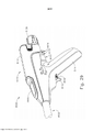
[0041] Figura 22 mostra uma vista em perspectiva parcial de um conjunto de cabo do grampeador circular alternativo exemplificador;[0041] Figure 22 shows a partial perspective view of an exemplary alternative circular stapler cable assembly;
[0042] Figura 23 mostra uma vista em recorte e em perspectiva do grampeador circular da Figura 22, com um conjunto de resgate de bigorna em uma posição neutra visível;[0042] Figure 23 shows a cutaway and perspective view of the circular stapler of Figure 22, with an anvil rescue assembly in a visible neutral position;
[0043] Figura 24 mostra uma vista em perspectiva detalhada do conjunto de resgate de bigorna da Figura 23;[0043] Figure 24 shows a detailed perspective view of the anvil rescue set of Figure 23;
[0044] Figura 25 mostra uma vista em perspectiva detalhada de um membro de acoplamento do conjunto de resgate de bigorna da Figura 23;[0044] Figure 25 shows a detailed perspective view of a coupling member of the anvil rescue assembly of Figure 23;
[0045] Figura 26 mostra uma vista lateral em seção transversal do membro de acoplamento da Figura 25, com a seção transversal tomada ao longo da linha 26-26 da Figura 25;[0045] Figure 26 shows a side view in cross section of the coupling member of Figure 25, with the cross section taken along line 26-26 of Figure 25;
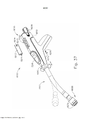
[0046] Figura 27 mostra uma vista em perspectiva detalhada de uma haste de atuação de trocarte do grampeador circular da Figura 22;[0046] Figure 27 shows a detailed perspective view of a trocar actuating rod of the circular stapler of Figure 22;
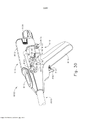
[0047] Figura 28 mostra uma vista em perspectiva detalhada do conjunto de resgate de bigorna da Figura 23 com o conjunto de resgate de bigorna em uma posição liberada;[0047] Figure 28 shows a detailed perspective view of the anvil rescue assembly of Figure 23 with the anvil rescue assembly in a released position;
[0048] Figura 29 mostra uma vista em perspectiva detalhada de um conjunto de cabo de outro grampeador circular alternativo exemplificador;[0048] Figure 29 shows a detailed perspective view of a cable assembly from another exemplary alternative circular stapler;
[0049] Figura 30 mostra uma vista em recorte e em perspectiva do grampeador circular da Figura 29, com um conjunto de resgate de bigorna em uma posição neutra visível;[0049] Figure 30 shows a cutaway and perspective view of the circular stapler of Figure 29, with an anvil rescue assembly in a visible neutral position;
[0050] Figura 31 mostra uma vista em perspectiva detalhada do conjunto de resgate de bigorna da Figura 30 com o conjunto de resgate de bigorna na posição neutra;[0050] Figure 31 shows a detailed perspective view of the anvil rescue set of Figure 30 with the anvil rescue set in the neutral position;
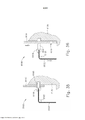
[0051] Figura 32 mostra uma vista em seção transversal superior detalhada do conjunto de resgate de bigorna da Figura 30, com a seção transversal tomada ao longo da linha 32-32 da Figura 31, com o conjunto de resgate de bigorna na posição neutra;[0051] Figure 32 shows a detailed top cross-sectional view of the anvil rescue assembly of Figure 30, with the cross section taken along line 32-32 of Figure 31, with the anvil rescue assembly in the neutral position;
[0052] Figura 33 mostra outra vista em seção transversal superior detalhada do conjunto de resgate de bigorna da Figura 30, com a seção transversal tomada ao longo da linha 32-32 da Figura 31, com o conjunto de resgate de bigorna em uma posição liberada;[0052] Figure 33 shows another detailed top cross-sectional view of the anvil rescue assembly of Figure 30, with the cross section taken along line 32-32 of Figure 31, with the anvil rescue assembly in a released position ;
[0053] Figura 34 mostra uma vista em seção transversal lateral detalhada de um conjunto de cabeça de grampeamento do grampeador circular da Figura 29, o conjunto de cabeça de grampeamento equipado com um conjunto de resgate de faca;[0053] Figure 34 shows a detailed side cross-sectional view of a stapler head assembly of the circular stapler of Figure 29, the stapler head assembly equipped with a knife rescue assembly;
[0054] Figura 35 mostra uma vista em seção transversal lateral detalhada do conjunto de resgate de faca da Figura 34, o conjunto de resgate de faca em uma posição neutra;[0054] Figure 35 shows a detailed side cross-sectional view of the knife rescue assembly of Figure 34, the knife rescue assembly in a neutral position;
[0055] Figura 36 mostra outra vista em seção transversal lateral detalhada do conjunto de resgate de faca da Figura 34, o conjunto de resgate de faca em uma posição liberada;[0055] Figure 36 shows another detailed side cross-sectional view of the knife rescue assembly of Figure 34, the knife rescue assembly in a released position;
[0056] Figura 37 mostra uma vista em perspectiva de ainda outro grampeador circular alternativo exemplificador, com uma porta de resgate removida;[0056] Figure 37 shows a perspective view of yet another exemplary alternative circular stapler, with a rescue port removed;
[0057] Figura 38 mostra uma vista em perspectiva detalhada de uma porção proximal do grampeador circular da Figura 37, com a porta de resgate removida e vários recursos de resgate visíveis;[0057] Figure 38 shows a detailed perspective view of a proximal portion of the circular stapler of Figure 37, with the rescue port removed and various rescue features visible;
[0058] Figura 39 mostra uma vista em perspectiva detalhada de um conjunto de cabo de ainda outro grampeador cirúrgico alternativo exemplificador;[0058] Figure 39 shows a detailed perspective view of a handle assembly of yet another exemplary alternative surgical stapler;
[0059] Figura 40 mostra uma vista em recorte e em perspectiva detalhada do conjunto de cabo do grampeador cirúrgico da Figura 39, com componentes internos de um botão de resgate do conjunto de cabeça de grampeamento manual visíveis;[0059] Figure 40 shows a cutaway and detailed perspective view of the surgical stapler handle assembly of Figure 39, with internal components of a rescue button of the manual stapler head assembly visible;
[0060] Figura 41 mostra uma vista em elevação lateral detalhada de um conjunto de acionamento de cabeça de grampeamento do grampeador cirúrgico da Figura 39;[0060] Figure 41 shows a detailed side elevation view of a stapling head drive assembly of the surgical stapler of Figure 39;
[0061] Figura 42 mostra uma vista em elevação lateral detalhada de um conjunto de acionamento de cabeça de grampeamento alternativo exemplificador que pode ser prontamente incorporado aos grampeadores circulares das Figuras 1, 22, 29, 37 e 39;[0061] Figure 42 shows a detailed side elevation view of an exemplary alternative stapling head drive assembly that can be readily incorporated into the circular staplers of Figures 1, 22, 29, 37 and 39;
[0062] Figura 43 mostra uma vista em elevação lateral detalhada de uma embreagem deslizante do conjunto de acionamento da cabeça de grampeamento da Figura 42, com as engrenagens da embreagem deslizante engatadas para transferir torque; e[0062] Figure 43 shows a detailed side elevation view of a sliding clutch of the clamping head drive assembly of Figure 42, with the sliding clutch gears engaged to transfer torque; and
[0063] Figura 44 mostra outra vista em elevação lateral detalhada da embreagem deslizante da Figura 43, com as engrenagens deslizando para evitar a transferência adicional de torque.[0063] Figure 44 shows another detailed side elevation view of the slipping clutch of Figure 43, with the gears sliding to prevent additional torque transfer.
[0064] Os desenhos não pretendem ser limitadores de modo algum e contempla-se que várias modalidades da tecnologia podem ser executadas em uma variedade de outras maneiras, incluindo aquelas não necessariamente representadas nos desenhos. Os desenhos incorporados em anexo e formando uma parte do relatório descritivo ilustram vários aspectos da presente tecnologia e, em conjunto com a descrição, servem para explicar os princípios da tecnologia; entende- se, entretanto, que esta tecnologia não se limita precisamente às disposições mostradas.[0064] The drawings are not intended to be limiting in any way and it is contemplated that various embodiments of the technology may be performed in a variety of other ways, including those not necessarily represented in the drawings. The drawings incorporated in the annex and forming a part of the specification illustrate various aspects of the present technology and, together with the description, serve to explain the principles of the technology; it is understood, however, that this technology is not limited precisely to the arrangements shown.
[0065] A descrição a seguir de certos exemplos da tecnologia não deve ser usada para limitar o seu escopo. Outros exemplos, recursos, aspectos, modalidades e vantagens da tecnologia se tornarão evidentes aos versados na técnica com a descrição a seguir, que é por meio de ilustrações, um dos melhores modos contemplados para realização da tecnologia. Conforme será compreendido, a tecnologia aqui descrita é capaz de outros aspectos diferentes e óbvios, todos sem desconsiderar a invenção. Consequentemente, os desenhos e as descrições devem ser considerados como de natureza ilustrativa e não restritiva.[0065] The following description of certain examples of the technology should not be used to limit its scope. Other examples, features, aspects, modalities and advantages of the technology will become apparent to those skilled in the art with the following description, which is by way of illustrations one of the best contemplated modes for realizing the technology. As will be understood, the technology described herein is capable of other different and obvious aspects, all without disregarding the invention. Consequently, the drawings and descriptions are to be considered as illustrative and not restrictive in nature.
[0066] As Figuras 1 a 2 ilustram um instrumento de grampeamento circular cirúrgico exemplificador 10 que pode ser usado para fornecer uma anastomose de ponta a ponta entre duas seções de um lúmen anatômico como uma porção do trato digestivo de um paciente. O instrumento 10 deste exemplo compreende um conjunto de cabo 100, um conjunto de haste 200, um conjunto de cabeça de grampeamento 300 e uma bigorna 400. O conjunto de cabo 100 compreende um invólucro 110 que define uma empunhadura de pistola 112 orientada obliquamente. Em algumas versões, a empunhadura da pistola 112 é orientada perpendicularmente. Em algumas outras versões, a empunhadura da pistola 112 é omitida. O conjunto de cabo 110 inclui, ainda, uma janela 114 que permite a visualização de uma agulha indicadora móvel 526 conforme será descrito com mais detalhes abaixo. Em algumas versões, uma série de marcas gráficas, regiões coloridas e/ou outros indicadores fixos estão em posição adjacente à janela 114 para fornecer um contexto visual para a agulha indicadora 526, facilitando assim a avaliação do operador da posição da agulha 526 dentro da janela 114. Várias características e configurações alternativas adequadas para o conjunto de cabo 112 serão evidentes para os versados na técnica em vista dos ensinamentos da presente invenção.[0066] Figures 1 to 2 illustrate an exemplary surgical
[0067] O instrumento 10 do presente exemplo inclui adicionalmente uma bateria 120. O conjunto de bateria 120 é operável para fornecer energia elétrica a um motor 160 na empunhadura da pistola 112, como será descrito em maiores detalhes abaixo. A bateria 120 pode ser removida do conjunto de cabo 100. Em particular, conforme mostrado nas Figuras 1 a 2, a bateria 120 pode ser inserida dentro de um soquete 116 definido pelo invólucro 110. Quando a bateria, 120 estiver totalmente inserida no soquete 116, as travas 122 da bateria 120 podem engatar resilientemente recursos do invólucro 110 para fornecer um encaixe por pressão. Para remover a bateria 120, o operador pode pressionar as travas 122 para dentro para desengatar as travas 122 dos recursos internos do invólucro 110 e então puxar a bateria 120 proximalmente a partir do soquete 116. Deve-se compreender que a bateria 120 e o conjunto de cabo 100 podem ter contatos elétricos, pinos e soquetes complementares, e/ou outros recursos que fornecem trajetórias para comunicação elétrica da bateria 120 para os componentes acionados eletricamente no conjunto de cabo 100, quando a bateria 120 é inserida no soquete 116. Deve-se compreender, também, que, em algumas versões, a bateria 120 é unitariamente incorporada dentro de conjunto de cabo 100 de modo que a bateria 120 não possa ser removida do conjunto de cabo 100.[0067] The
[0068] O conjunto do eixo de acionamento 200 se estende distalmente a partir do conjunto de cabo 100 e inclui uma curva pré- formada. Em algumas versões, a curva pré-formada é configurada de modo a facilitar o posicionamento do conjunto de cabeça de grampeamento 300 dentro do cólon do paciente. Vários ângulos ou raios de curva adequados que podem ser usados serão evidentes para aqueles versados na técnica em vista dos ensinamentos da presente invenção. Em algumas outras versões, o conjunto de eixo de acionamento 200 é reto, de modo que o conjunto de eixo de acionamento 200 não apresenta uma curva pré-formada. Vários componentes exemplificadores que podem ser incorporados ao conjunto de eixo de acionamento 100 serão descritos em maior detalhe abaixo.[0068] The
[0069] O conjunto de cabeça de grampeamento 300 está situado na extremidade distal do conjunto de eixo de acionamento 200. Conforme mostrado nas Figuras 1 a 2, e conforme será descrito com mais detalhes abaixo, a bigorna 400 é configurada para se acoplar de modo removível ao conjunto do eixo de acionamento 200, adjacente ao conjunto de cabeça de grampeamento 300. Como também será descrito em maiores detalhes abaixo, a bigorna 400 e o conjunto de cabeça de grampeamento 300 são configurados para cooperar para manipular o tecido de três formas, incluindo pinçamento do tecido, corte do tecido e grampeamento do tecido. Um botão 130, na extremidade proximal do conjunto de cabo 100 é giratório em relação ao invólucro 110 para proporcionar pinçamento preciso do tecido entre a bigorna 400 e o conjunto de cabeça de grampeamento 300. Quando um gatilho de segurança 140 do conjunto de cabo 100 é girado na direção oposta a um gatilho de disparo 150 do conjunto de cabo 100, o gatilho de disparo 150 pode ser atuado para, assim, proporcionar o corte e o grampeamento do tecido.[0069] The stapling
[0070] Na discussão a seguir de bigorna 400, os termos "distal" e "proximal" (e suas variações) serão usados em referência à orientação da bigorna 400 quando a bigorna 400 é acoplada ao conjunto de eixo de acionamento 200 do instrumento 10. Portanto, os recursos proximais da bigorna 400 estarão mais próximos do operador do instrumento 10; enquanto os recursos distais da bigorna 400 estarão mais afastados do operador do instrumento 10.[0070] In the following discussion of
[0071] Conforme se pode observar melhor nas Figuras 3 a 5, a bigorna 400 do presente exemplo compreende uma cabeça 410 e uma haste 420. A cabeça 410 inclui uma superfície proximal 412 que define uma pluralidade de bolsos formadores de grampo 414. Os bolsos formadores de grampo 414 são dispostos em duas matrizes anulares concêntricas. Em algumas outras versões, os bolsos formadores de grampo 414 são dispostos em três ou mais matrizes anulares concêntricas. Os bolsos formadores de grampo 414 são configurados para deformar os grampos à medida que os grampos são acionados para dentro dos bolsos formadores de grampo 414. Por exemplo, cada bolso de formação de grampo 414 pode deformar um grampo que tenha geralmente um formato de "U" em um formato de "B", conforme é conhecido na técnica. Conforme se pode observar melhor na Figura 4, a superfície proximal 412 termina em uma borda interna 416, a qual define um contorno externo de uma reentrância anular 418 da haste circundante 420.[0071] As best seen in Figures 3 to 5, the
[0072] A haste 420 define um orifício 422 e inclui um par de membros de trava pivotantes 430 posicionados no orifício 422. Conforme se pode observar melhor na Figura 5, cada membro de trava 430 inclui uma extremidade distal em forma de "T" 432, uma extremidade proximal arredondada 434, e uma prateleira de trava 436 localizada distalmente em relação à extremidade proximal 434. As extremidades distais em forma de "T" 432 prendem os membros de trava 430 dentro do orifício 422. Os membros de trava 430 são posicionados dentro do orifício 422, de modo que as extremidades distais 434 sejam posicionadas nas extremidades proximais das aberturas laterais 424, que são formadas através da parede lateral da haste 420. As aberturas laterais 424 fornecem, assim, uma distância para as extremidades distais 434 e as prateleiras de trava 436 defletirem radialmente para fora a partir do eixo longitudinal definido pela haste 420. Entretanto, os membros de trava 430 são configurados para forçarem resilientemente as extremidades distais 434 e as prateleiras de trava 436 radialmente internamente em direção ao eixo geométrico longitudinal definido pela haste 420. Os membros de trava 430 agem, assim, como clipes de retenção. Isto permite que a bigorna 400 seja presa de modo removível a um trocarte 330 do conjunto de cabeça de grampeamento 300 conforme será descrito com mais detalhes abaixo. Deve-se compreender, no entanto, que os membros de trava 436 são meramente opcionais. A bigorna 400 pode ser presa de modo removível a um trocarte 330 usando quaisquer outros componentes, recursos ou técnicas adequadas.[0072] The
[0073] Em adição ou em substituição ao supracitado, a bigorna 400 pode ser adicionalmente construída e ser operável de acordo com pelo menos alguns dos ensinamentos da Patente US n° 5.205.459; Patente US n° 5.271.544; Patente US n° 5.275.322; Patente US n° 5.285.945; Patente US n° 5.292.053; Patente US n° 5.333.773; Patente US n° 5.350.104; Patente US n° 5.533.661; e/ou a Patente US n° 8.910.847, estando as descrições das mesmas aqui incorporadas, a título de referência. Outras configurações adequadas adicionais serão aparentes ao versado na técnica com base nos ensinamentos da presente invenção.[0073] In addition to or in lieu of the foregoing, the
[0074] Conforme se pode observar melhor nas Figuras 6 a 7, o conjunto de cabeça de grampeamento 300 do presente exemplo é acoplado a uma extremidade distal do conjunto de eixo de acionamento 200 e compreende um invólucro tubular 310 que aloja um membro acionador de grampo deslizante 350. Um membro de núcleo interno similar a um cilindro 312 se estende distalmente dentro do invólucro tubular 310. O invólucro tubular 310 é preso de modo fixo a uma bainha externa 210 do conjunto de eixo de acionamento 200, de modo que o invólucro tubular 310 sirva como um piso mecânico para o conjunto de cabeça de grampeamento 300.[0074] As best seen in Figures 6 to 7, the stapling
[0075] O trocarte 330 é posicionado coaxialmente dentro do membro de núcleo interno 312 do invólucro tubular 310. Conforme será descrito com mais detalhes abaixo, o trocarte 330 é operável para transladar distalmente e proximalmente em relação ao invólucro tubular 310 em resposta à rotação do botão 130 em relação ao invólucro 110 de conjunto de cabo 100. O trocarte 330 compreende um eixo de acionamento 332 e uma cabeça 334. A cabeça 334 inclui uma ponta pontiaguda 336 e uma superfície proximal que se estende para dentro 338. O eixo de acionamento 332 fornece, portanto, um diâmetro externo reduzido bem adjacente à cabeça 334, com a superfície 338 fornecendo uma transição entre o diâmetro externo reduzido da haste 332 e o diâmetro externo da cabeça 334. Embora a ponta 336 seja pontiaguda no presente exemplo, a ponta 336 não é afiada. Assim, a ponta 336 não causa trauma facilmente ao tecido devido ao contato inadvertido com o tecido. A cabeça 334 e a porção distal do eixo de acionamento 332 são configuradas para inserção no orifício 422 da bigorna 420. A superfície proximal 338 e prateleiras de trava 436 têm posições e configurações complementares de modo que as prateleiras de trava 436 engatam a superfície proximal 338 quando a haste 420 da bigorna 400 está totalmente assentada no trocarte 330. A bigorna 400 é, assim, presa ao trocarte 330 através de um encaixe por pressão dos membros de trava 430.[0075] The
[0076] O membro acionador de grampo 350 é operável para atuar longitudinalmente dentro do invólucro tubular 310 em resposta à ativação do motor 160 conforme será descrito com mais detalhes abaixo. O membro acionador de grampo 350 inclui duas matrizes anulares concêntricas distalmente apresentadas de acionadores de grampo 352. Os acionadores de grampo 352 são dispostos de modo a corresponderem à disposição dos bolsos formadores de grampo 414 descritos acima. Assim, cada acionador de grampo 352 é configurado para acionar um grampo correspondente em um bolso formador de grampo correspondente 414 quando o conjunto de cabeça de grampeamento 300 é atuado. Deve-se compreender que a disposição dos acionadores de grampo 352 pode ser modificada, bem como a disposição dos bolsos formadores de grampo 414 como descrito acima. O membro acionador de grampo 350 também define um orifício 354 que é configurado para receber coaxialmente o membro núcleo 312 do invólucro tubular 310. Uma matriz anular de pinos 356 se projeta distalmente a partir de um orifício circundante de superfície distalmente apresentada 354.[0076] The
[0077] Um membro de faca similar a um cilindro 340 é coaxialmente posicionado dentro do membro acionador de grampos 350. O membro de faca 340 inclui um gume cortante circular afiado, apresentado distalmente 342. O membro de faca 340 é dimensionado de modo que o membro de faca 340 defina um diâmetro externo que é menor que o diâmetro definido pela matriz anular interna dos acionadores de grampo 352. O membro de faca 340 também define uma abertura que é configurada para receber coaxialmente o membro núcleo 312 do invólucro tubular 310. Uma matriz anular das aberturas 346 formadas no membro de faca 340 é configurada de modo a complementar a matriz anular de pinos 356 do membro acionador de grampos 350, de modo que o membro de faca 340 seja preso de modo fixo ao membro acionador de grampo 350 por meio de pinos 356 e aberturas 346. Outras relações estruturais adequadas entre o membro de faca 340 e o membro acionador de grampeador 350 ficarão evidentes para aqueles versados na técnica em vista dos ensinamentos da presente invenção.[0077] A cylinder-
[0078] O elemento de plataforma 320 é preso de maneira fixa ao invólucro tubular 310. O membro de plataforma 320 inclui uma superfície de plataforma distalmente apresentada 322 que define duas matrizes anulares concêntricas de aberturas de grampo 324. As aberturas de grampo 324 são dispostas de modo a corresponderem à disposição dos acionadores de grampo 352 e bolsos formadores de grampo 414 descritos acima. Dessa forma, cada abertura de grampo 324 é configurada para fornecer uma trajetória a um acionador de grampo correspondente 352 para acionar um grampo correspondente através do membro de plataforma 320 e para dentro de um bolso formador de grampo correspondente 414 quando o conjunto de cabeça de grampeamento 300 é acionado. Deve-se compreender que a disposição das aberturas de grampo 322 pode ser modificada bem como a disposição dos bolsos formadores de grampo 414 como descrito acima. Deve-se compreender, também, que várias estruturas e técnicas podem ser usadas para conter os grampos dentro do conjunto de cabeça de grampeamento 300 antes de o conjunto de cabeça de grampeamento 300 ser atuado. Essas estruturas e técnicas que são usadas para conter grampos dentro do conjunto de cabeça de grampeamento 300 podem evitar que os grampos caiam inadvertidamente através das aberturas para grampo 324 antes que o conjunto de cabeça de grampeamento 300 seja atuado. Várias formas adequadas que essas estruturas e técnicas podem assumir serão aparentes para aqueles versados na técnica em vista dos ensinamentos da presente invenção.[0078] The
[0079] Conforme se pode observar melhor na Figura 6, o membro de plataforma 320 define um diâmetro interno que é apenas ligeiramente maior que o diâmetro externo definido pelo membro de faca 340. O membro de plataforma 320, dessa forma, é configurado para permitir que o membro de faca 340 translade distalmente para um ponto onde o gume cortante 342 é distal à superfície da plataforma 322.[0079] As best seen in Figure 6, the
[0080] Em adição ou em substituição ao supracitado, o conjunto de cabeça de grampeamento 300 pode ser construído ainda e operável de acordo com pelo menos alguns dos ensinamentos da Patente US n° 5.205.459; Patente US n° 5.271.544; Patente US n° 5.275.322; Patente US n° 5.285.945; Patente US n° 5.292.053; Patente US n° 5.333.773; Patente US n° 5.350.104; Patente US n° 5.533.661; e/ou a Patente US n° 8.910.847, estando as descrições das mesmas aqui incorporadas, a título de referência. Outras configurações adequadas serão aparentes para o versado na técnica com base nos ensinamentos da presente invenção.[0080] In addition to or in place of the foregoing, the stapling
[0081] A Figura 8 mostra vários componentes do conjunto do eixo de acionamento 200, que acopla os componentes do conjunto de cabeça de grampeamento 300 a componentes do conjunto de cabo 100. Em particular, e conforme observado acima, o conjunto do eixo de acionamento 200 inclui uma bainha externa 210 que se estende entre o conjunto de cabo 100 e o invólucro tubular 310. No presente exemplo, a bainha externa 210 é rígida e inclui uma seção curva pré-formada, como observado acima.[0081] Figure 8 shows various components of the
[0082] O conjunto do eixo de acionamento 200 inclui ainda uma haste de atuação de trocarte 220 e um conjunto de banda de atuação do trocarte 230. A extremidade distal do conjunto de banda de atuação do trocarte 230 é presa de maneira fixa à extremidade proximal do eixo do trocarte 332. A extremidade proximal do conjunto de banda de atuação do trocarte 230 é presa de maneira fixa à extremidade distal da haste de atuação do trocarte 220. Portanto, deve-se compreender que o trocarte 330 irá transladar longitudinalmente em relação à bainha externa 210 em resposta à translação do conjunto da banda de atuação do trocarte 230 e haste de atuação do trocarte 220 em relação à bainha externa 210. O conjunto da banda de atuação do trocarte 230 é configurado para flexionar de modo que o conjunto de banda de atuação do trocarte 230 possa seguir ao longo da curva pré-formada no conjunto de eixo de acionamento 200 conforme o conjunto de banda de atuação do trocarte 230 é transladado longitudinalmente em relação à bainha externa 210. Entretanto, o conjunto de banda de atuação do trocarte 230 tem resistência de coluna suficiente e resistência à tração para transferir as forças distais e proximais da haste de atuação do trocarte 220 para o eixo de acionamento do trocarte 332. A haste de atuação do trocarte 220 é rígida. Um clipe 222 está ligado de modo fixo à haste de atuação do trocarte 220 e é configurado para cooperar com recursos complementares dentro do conjunto de cabo 100 para evitar que a haste de atuação do trocarte 220 gire dentro do conjunto de cabo 100 enquanto ainda permite que a haste de atuação do trocarte 220 translade longitudinalmente dentro do conjunto de cabo 100. A haste de atuação do trocarte 220 ainda inclui um rosqueamento helicoidal grosso 224 e um rosqueamento helicoidal fino 226. Detalhes relacionados ao movimento da haste de atuação do trocarte 220 serão descritos com mais detalhes abaixo.[0082] The
[0083] O conjunto de eixo de acionamento 200 inclui ainda um acionador de conjunto de cabeça de grampeamento 240 que é recebido de modo deslizante dentro da bainha externa 210. A extremidade distal do acionador do conjunto de cabeça de grampeamento 240 é presa de maneira fixa à extremidade proximal do membro acionador de grampo 350. A extremidade proximal do acionador do conjunto de cabeça de grampeamento 240 é presa a um bráquete de acionamento 250 através de um pino 242. Portanto, deve-se entender que o membro acionador de grampo 350 irá transladar longitudinalmente em relação à bainha externa 210 em resposta à translação do acionador do conjunto de cabeça de grampeamento 240 e bráquete de acionamento 250 em relação à bainha externa 210. O acionador do conjunto de cabeça de grampeamento 240 é configurado para flexionar de modo que o acionador do conjunto de cabeça de grampeamento 240 possa seguir ao longo da curva pré-formada no conjunto de eixo de acionamento 200 conforme o acionador do conjunto de cabeça de grampeamento 240 é transladado longitudinalmente em relação à bainha externa 210. Entretanto, o acionador do conjunto de cabeça de grampeamento 240 tem resistência de coluna suficiente para transferir as forças distais do bráquete de acionamento 250 para o membro acionador de grampo 350. Detalhes relacionados ao movimento do bráquete de acionamento 250 serão descritos com mais detalhes abaixo.[0083] The
[0084] Embora não seja mostrado na Figura 8, deve ser entendido que o conjunto do eixo de acionamento 200 pode incluir, também, um ou mais elementos espaçados dentro da bainha externa 210. Esses elementos espaçados podem ser configurados para suportar o conjunto de banda de atuação de trocarte 230 e/ou acionador do conjunto de cabeça de grampeamento 240 conforme o conjunto de banda de atuação do trocarte 230 e/ou acionador do conjunto de cabeça de grampeamento 240 transladam através da bainha externa 210. Por exemplo, esses elementos espaçadores podem evitar que o conjunto de banda de atuação de trocarte 230 e/ou acionador do conjunto de cabeça de grampeamento 240 abaulem conforme o conjunto de banda de atuação do trocarte 230 e/ou acionador do conjunto de cabeça de grampeamento 240 transladam através da bainha externa 210. Várias formas adequadas que esses elementos espaçadores podem assumir serão aparentes para as pessoas versadas na técnica em vista dos ensinamentos da presente invenção.[0084] Although not shown in Figure 8, it should be understood that the
[0085] Além disso ou em substituição ao supracitado, o conjunto de eixo de acionamento 200 pode ser ainda construído e operável de acordo com ao menos alguns dos ensinamentos da Patente US n° 5.205.459; Patente US n° 5.271.544; Patente US n° 5.275.322; Patente US n° 5.285.945; Patente US n° 5.292.053; Patente US n° 5.333.773; Patente US n° 5.350.104; Patente US n° 5.533.661; e/ou a Patente US n° 8.910.847, estando as descrições das mesmas aqui incorporadas, a título de referência. Outras configurações adequadas serão aparentes para o versado na técnica com base nos ensinamentos da presente invenção.[0085] In addition to or in place of the foregoing, the
[0086] Conforme mostrado na Figura 9, o conjunto de cabo 100 inclui vários componentes que têm por finalidade atuar a bigorna 400 e conjunto de cabeça de grampeamento 300. O conjunto de cabo 100 também inclui componentes que são operáveis para travar seletivamente os gatilhos 140, 150 com base na posição da bigorna 400 em relação ao conjunto de cabeça de grampeamento 300. Quando os gatilhos 140, 150 são travados, o gatilho de disparo 150 é impedido de iniciar a atuação do conjunto de cabeça de grampeamento 300. Dessa forma, o gatilho 150 é operável apenas para iniciar a atuação do conjunto de cabeça de grampeamento 300, quando a posição da bigorna 400 em relação ao conjunto de cabeça de grampeamento 300 está dentro de uma faixa predefinida. Os componentes do conjunto de cabo 100 que fornecem a operabilidade anteriormente mencionada serão descritos em mais detalhes abaixo.[0086] As shown in Figure 9, the
[0087] O botão 130 projeta-se proximalmente a partir do invólucro 110 do conjunto de cabo e pode ser girado em relação ao invólucro 110. Conforme mostrado na Figura 9, uma porca 160 está presa à extremidade distal do botão 130. No presente exemplo, a porca 160 está presa de modo fixo à extremidade distal do botão 130 de modo que a porca 160 gire unitariamente com o botão 130. A porca 160 e o botão 130 são configurados para cooperarem com a haste de atuação do trocarte 220 para, dessa forma, transladarem a haste de atuação do trocarte 220 longitudinalmente em relação ao invólucro 110 em resposta à rotação da porca 160 e botão 130 em relação ao invólucro 110. Como observado acima, o trocarte 330 irá transladar longitudinalmente em relação à bainha externa 210, em resposta à translação da haste de atuação do trocarte 220 em relação à bainha externa 210 e invólucro 110.[0087] The
[0088] A porção proximal da haste de atuação do trocarte 220 é colocada dentro do conjunto de cabo 100 para engatar a porca 160 e o botão 130. Em particular, a haste de atuação do trocarte 220 é posicionada dentro do conjunto de cabo 100 de modo que o rosqueamento helicoidal grosso 224 acople seletivamente um recurso de engate de rosca não mostrado no interior da porca 160; e de modo que o rosqueamento helicoidal fino 226 irá seletivamente engatar um recurso de engate de rosca não mostrado dentro do botão 130. Em algumas versões, o recurso de engate de rosca da porca 160 compreende uma aba direcionada para dentro; enquanto o recurso de engate de rosca do botão 130 compreende um rosqueamento helicoidal. Outras formas adequadas que esses recursos de engate de rosca podem assumir serão aparentes para as pessoas versadas na técnica em vista dos ensinamentos da presente invenção.[0088] The proximal portion of the
[0089] No presente exemplo, quando a porca 160 e o botão 130 são girados em relação ao invólucro 110, a haste de atuação de trocarte 220 se move de maneira proximal através de uma primeira faixa de movimento longitudinal onde um rosqueamento helicoidal grosso 224 é engatado com a porca 160 para fornecer uma taxa de translação relativamente rápida. O rosqueamento helicoidal fino 226 não é engatado com o botão 130 durante esta faixa de movimento. Quando a porca 160 e o botão 130 são adicionalmente girados em relação ao invólucro 110 após a haste de atuação de trocarte 220 completar a primeira faixa de movimento, a haste de atuação de trocarte 220 continuará a se deslocar proximalmente através da segunda faixa de movimento longitudinal onde o rosqueamento helicoidal fino 226 é engatado com o botão 130 para fornecer uma taxa de translação relativamente lenta. Dessa forma, a haste de atuação do trocarte 220 irá transladar de maneira proximal através de uma sequência de translação rápida seguida pela translação lenta, com base no engate entre o rosqueamento helicoidal grosso 224 e a porca 160 seguida pelo engate entre o rosqueamento helicoidal fino 226 e o botão 130.[0089] In the present example, when the
[0090] Deve-se compreender que quando a bigorna 400 é acoplada ao trocarte 330, a rotação do botão 130 irá fornecer a translação correspondente da bigorna em relação ao conjunto de cabeça de grampeamento 300. Também deve ser entendido que o botão 130 pode ser girado em uma primeira direção angular (por exemplo, em sentido horário) para retrair a bigorna 400 em direção ao conjunto de cabeça de grampeamento, 300; e em uma segunda direção angular (por exemplo, anti-horária) para avançar a bigorna 400 para longe do conjunto de cabeça de grampeamento 300. Dessa forma, o botão 130 pode ser usado para ajustar a distância do vão d entre as superfícies opostas 412, 322 da bigorna 400 e conjunto de cabeça de grampeamento 300 até uma distância do vão adequada d ter sido alcançado conforme mostrado na Figura 21C e conforme descrito com mais detalhes abaixo.[0090] It should be understood that when the
[0091] Conforme observado acima, o botão pode ser usado para ajustar a distância do vão d entre as superfícies opostas 412, 322 da bigorna 400 e do conjunto de cabeça de grampeamento 300. O ajuste de uma distância de vão d adequada antes de atuar o conjunto de cabeça de grampeamento 300 pode ser de importância crítica para o sucesso de uma anastomose. Por exemplo, se a distância do vão d for muito grande, os grampos que são instalados no local de anastomose podem não ser suficientemente formados pelos bolsos formadores de grampo 414. Isso pode resultar em vazamentos no local da anastomose, e, em alguns casos, pode finalmente levar à separação das seções do lúmen anatômico que são unidas em um local de anastomose. Se a distância do vão d for pequena demais, a estrutura interna do tecido comprimido entre as superfícies 412, 322 pode ser danificada até o ponto em que a integridade estrutural do tecido é comprometida. Isto pode evitar que o tecido segure adequadamente os grampos formados, o que novamente pode resultar em vazamentos ou outras falhas da anastomose. Portanto, pode ser desejável fornecer ao operador alguma forma de feedback indicando se a distância do vão d está dentro de uma faixa adequada. Pode ser desejável evitar que o operador atue o conjunto de cabeça de grampeamento 300 a menos que a distância do vão d esteja dentro de uma faixa adequada.[0091] As noted above, the knob can be used to adjust the d-span distance between opposing
[0092] As Figuras 9 a 12E mostram componentes que fornecem feedback para o operador para indicar se a distância do vão d está dentro de uma faixa adequada; e evitar que o operador atue o conjunto de cabeça de grampeamento 300 a menos que a distância do vão d esteja dentro de uma faixa adequada. Conforme se pode observar melhor nas Figuras 12B a 12C, um bráquete 500 é configurado e posicionado para se mover em resposta ao movimento da haste de atuação do trocarte 220. Conforme se pode observar melhor na Figura 10, o bráquete 500 inclui um corpo rígido 502 que define uma primeira fenda 504, uma segunda fenda 506, e uma terceira fenda 508. Um recurso vertical 510 é posicionado na extremidade proximal do corpo 502, e define uma abertura 512. A haste de atuação de trocarte 220 se estende coaxialmente através da abertura 512. Conforme mostrado na Figura 9, uma mola em espiral 170 é interposta à extremidade proximal do recurso vertical 510 e um recurso de anteparo rígido que é definido pelo invólucro 110, que forma um moente de suporte para a porca 160. O anteparo é fixado no interior do invólucro 110 e, assim, fornece um solo à extremidade proximal da mola em espiral 170, de modo que a mola em espiral 170 confere resilientemente uma inclinação distal ao bráquete 500 por meio do recurso vertical 510. O bráquete 500 inclui, ainda, um flange apresentado lateralmente 516 na extremidade distal do corpo 502. O flange 516 define uma fenda 514.[0092] Figures 9 to 12E show components that provide feedback to the operator to indicate whether the span d distance is within an appropriate range; and preventing the operator from actuating the stapling
[0093] Conforme se pode observar melhor na Figuras 12B a 12C, um membro indicador 520 é configurado para pivotar em resposta à translação do bráquete 500. Conforme se pode observar melhor na Figura 11, o membro indicador 520 compreende um braço vertical 522, um pino de encaixe por pressão 524 que se projeta lateralmente a partir de uma extremidade inferior de braço 522, uma agulha indicadora 526 que se projeta lateralmente a partir de uma extremidade superior do braço 522, e um pino de acoplamento 528 que se projeta lateralmente a partir de uma região intermediária do braço 522. O pino de encaixe por pressão 524 é configurado para encaixar por pressão em uma reentrância complementar fornecida pelo invólucro 110. Desse modo, o pino de encaixe por pressão 524 prende o membro indicador 520 ao invólucro 110, permitindo ainda que o membro indicador 520 pivote em relação ao invólucro 110 em torno do eixo longitudinal do pino de encaixe por pressão 524. A agulha indicadora 526 está posicionada de modo a ser visível através da janela 114 do conjunto de cabo 110 de modo a indicar visualmente a posição pivotante do membro indicador 520. O pino de acoplamento 528 é recebido de maneira deslizante na fenda 514 do flange 516 do bráquete 500. Esse engate entre o membro indicador 520, o invólucro 110 e o bráquete 500 fornece o movimento pivotante do membro indicador 520 em resposta à translação do bráquete 500.[0093] As best seen in Figures 12B to 12C, an
[0094] O bráquete 500 é configurado para impedir e permitir seletivamente a atuação dos gatilhos 140, 150. Em particular, as fendas 504, 506 do bráquete 500 são configuradas para fornecerem seletivamente folga para atuação dos gatilhos 140, 150. Conforme mostrado nas Figuras 12A a 12E, o gatilho de segurança 140 é acoplado de modo articulado ao primeiro membro vertical 144. O primeiro membro vertical 144 é acoplado ao invólucro 110 de modo que o primeiro membro vertical 144 seja configurado para transladar ascendentemente em resposta à pivotação do gatilho de segurança 140 no sentido da empunhadura da pistola 112. Entretanto, o corpo 502 do bráquete 500 é configurado para evitar este movimento do primeiro membro vertical 144 e gatilho de segurança 140 pelo engate da extremidade superior 146 do primeiro membro vertical 144. O corpo 502, desse modo, bloqueia o movimento do primeiro membro vertical 144 e gatilho de segurança 140 até que o bráquete 500 seja movido para uma posição onde a fenda 506 fica alinhada com a extremidade superior 146 de modo a fornecer uma folga para o movimento ascendente do primeiro membro vertical 144. Deve-se entender, portanto, que o gatilho de segurança 140 não pode ser pivotado em direção à empunhadura da pistola 112 até a fenda 506 ser posicionada sobre a extremidade superior 146.[0094]
[0095] De modo similar, o gatilho de disparo 150 é acoplado de modo articulado ao segundo membro vertical 154. O segundo membro vertical 154 é acoplado ao invólucro 110 de modo que o segundo membro vertical 154 seja configurado para transladar para cima em resposta à rotação do gatilho de segurança 150 no sentido da empunhadura da pistola 112. Entretanto, o corpo 502 do bráquete 500 é configurado para evitar este movimento do segundo membro vertical 154 e gatilho de disparo 150 pelo engate da extremidade superior 156 do segundo membro vertical 154. Mesmo que o gatilho de segurança 140 seja girado para fora do caminho para, de outro modo, permitir o movimento do gatilho de disparo 150, o corpo 502 bloqueia o movimento do segundo membro vertical 154 e gatilho de disparo 150 até que o bráquete 500 seja movido para uma posição onde a fenda 504 está alinhada com a extremidade superior 156 de modo a fornecer uma folga para o movimento para cima do segundo membro vertical 154. Deve-se portanto entender que, mesmo que o gatilho de segurança 140 seja pivotado para fora do caminho para caso contrário permitir o movimento do gatilho de disparo 150, o gatilho de disparo 150 não pode ser articulado na direção da empunhadura tipo pistola 112 até a fenda 504 ser posicionada sobre a extremidade superior 156.[0095] Similarly, the
[0096] A terceira fenda 508 é configurada para receber uma saliência que se projeta para baixo 223 do clipe 222, que está rigidamente preso à haste de atuação do trocarte 220. Enquanto o invólucro 110 é configurado para permitir que o bráquete 500 translade longitudinalmente dentro do invólucro 110, o invólucro 110 inclui trilhos, canais e/ou outros recursos que impedem que o bráquete 500 gire dentro do invólucro 110. Dessa forma, o posicionamento da saliência 223 na fenda 508 evita que o clipe 222 e a haste de atuação do trocarte 220 girem dentro do invólucro 110. No entanto, a saliência 223 e a fenda 508 permitem que o bráquete 500 translade longitudinalmente dentro do invólucro 110 conforme será descrito com mais detalhes abaixo.[0096] The
[0097] As Figuras 12A - 12E mostram os componentes acima descritos em vários estágios de operação. Em particular, na Figura 12A, a haste de atuação do trocarte 220 está em uma posição mais distal, de modo que o trocarte 330 está em uma posição mais distal. Neste estágio, o operador pode acoplar a bigorna 400 ao trocarte 330 pela inserção do trocarte 330 dentro do orifício 422 até os membros de trava 430 serem presos à cabeça 334 do trocarte 330. O operador então gira o botão 130, que gira a porca 160. Conforme o botão 130 e a porca 160 giram, o engate entre o rosqueamento helicoidal grosso 224 da haste de atuação do trocarte 220 e os recursos complementar da porca 160 faz com que a haste de atuação do trocarte 220 retraia proximalmente a uma taxa relativamente rápida, de modo que a haste de atuação do trocarte 220 atinge a posição mostrada na Figura 12B. Isto fornece retração proximal da haste de atuação do trocarte 220 e fornece a retração do trocarte 330 e da bigorna 400. Conforme a haste de atuação do trocarte 220 se move da posição mostrada na Figura 12A para a posição mostrada na Figura 12B, o bráquete 500 permanece estacionário. Isto é devido ao fato de que o clipe 222 é espaçado a partir de recurso vertical 510 no estágio mostrado na Figura 12A e não engata o recurso vertical 510 até que a haste de atuação do trocarte 220 alcance a posição mostrada na Figura 12B.[0097] Figures 12A - 12E show the components described above in various stages of operation. In particular, in Figure 12A, the
[0098] Após alcançar o estágio mostrado na Figura 12B, o operador pode continuar a girar o botão 130 e a porca 160, o que causa a retração proximal adicional da haste de atuação do trocarte 220, conforme mostrado na Figura 12C. Isso, obviamente, causa retração proximal adicional do trocarte 330 e bigorna 400. Conforme a haste de atuação do trocarte 220 se move da posição mostrada na Figura 12B para a posição mostrada na Figura 12C, o clipe 222 se apóia contra o bráquete 500, acionando o bráquete 500 proximalmente. O movimento proximal do bráquete 500 faz com que o membro indicador 520 gire a partir da posição mostrada na Figura 12B para a posição mostrada na Figura 12C devido ao posicionamento do pino 528 na fenda 514 do flange 516.[0098] After reaching the stage shown in Figure 12B, the operator can continue to rotate the
[0099] Conforme o membro indicador 520 gira a partir da posição mostrada na Figura 12B para a posição mostrada na Figura 12C, o operador pode observar a posição da agulha indicadora 526 através da janela 114 do conjunto de cabo 110. Como observado acima, uma série de marcas gráficas, regiões coloridas e/ou outros indicadores fixos pode ser posicionada em posição adjacente à janela 114 para fornecer um contexto visual para a agulha indicadora 526, facilitando assim a avaliação do operador da posição da agulha 526 dentro da janela 114. Deve-se compreender que a posição da agulha 526 dentro da janela 114 será indicativa da posição longitudinal do trocarte 330 e da bigorna 400. A posição da agulha 526 dentro da janela 114 irá indicar então a distância do vão d entre as superfícies opostas 412, 322 da bigorna 400 e do conjunto de cabeça de grampeamento 300. Ao observar a posição da agulha 526 dentro da janela 114, o operador pode girar o botão 130 em sentido horário ou anti-horário para retrair ou avançar adicionalmente o trocarte 330 e a bigorna 400, fornecendo assim ajuste fino da distância do vão d até que uma distância de vão desejada d seja obtida dentro de uma faixa adequada.[0099] As the indicating
[00100] De modo a fornecer o controle fino do ajuste da distância do vão d no estágio mostrado na Figura 12C, a haste de atuação do trocarte 220 estará em uma posição longitudinal onde o rosqueamento helicoidal fino 226 é engatado a um recurso complementar do botão 130 e um rosqueamento helicoidal grosso 224 é desengatado do recurso complementar da porca 160. Em algumas versões, o rosqueamento helicoidal grosso 224 desengata a porca 160 e o rosqueamento helicoidal fino 226 começa a engatar o botão 130 uma vez que a haste de atuação do trocarte 220 atinge a posição longitudinal mostrada na Figura 12B isto é, quando o clipe 222 primeiro engata o membro vertical 510. Em algumas outras versões, a transição do engate pelo rosqueamento helicoidal grosso 224 para o rosqueamento helicoidal fino 226 ocorre em algum momento entre o estágio mostrado na Figura 12B e o estágio mostrado na Figura 12C. Outros estágios adequados nos quais a transição de grosso para fino pode ocorrer serão evidentes para aqueles versados na técnica em vista dos ensinamentos da presente invenção. Também deve ser entendido que algumas versões alternativas da haste de atuação do trocarte 220 podem ter apenas uma única seção de rosqueamento, com o passo do rosqueamento sendo consistente ao longo do comprimento do rosqueamento. Em outras palavras, a haste de atuação do trocarte 220 não precisa necessariamente ter duas seções diferentes de rosqueamento 224, 226 com diferentes passos.[00100] In order to provide fine control of adjusting the gap distance d in the stage shown in Figure 12C, the
[00101] No estágio mostrado na Figura 12C, a fenda 506 é alinhada com a extremidade superior 146, de modo a fornecer uma folga para o movimento ascendente para cima do primeiro membro vertical 144. De modo similar, a fenda 504 é alinhada com a extremidade superior 156, de modo a fornecer uma folga para o movimento para cima do segundo membro vertical 154. No presente exemplo, as fendas 504, 506 são dimensionadas e posicionadas de modo que as fendas 504, 506 só forneçam espaço para o movimento ascendente dos membros verticais 144, 154 quando a distância do vão D está dentro de uma faixa clinicamente aceitável. A título de exemplo apenas, uma "faixa clinicamente aceitável" para a distância do vão d pode variar entre aproximadamente 0,280 centímetros e aproximadamente 0,10 centímetros aproximadamente 0,110 polegadas e aproximadamente 0,040 polegadas. Como outro exemplo meramente ilustrativo, uma "faixa clinicamente aceitável" para a distância do vão d pode variar entre aproximadamente 0,280 centímetros e aproximadamente 0,051 centímetro (aproximadamente 0,110 polegada e aproximadamente 0,020 polegada). Mesmo quando as fendas 504, 506 são posicionadas de modo a fornecerem uma folga ao movimento ascendente dos membros verticais 144, 154, conforme mostrado na Figura 12C, o gatilho de segurança 140 irá ainda bloquear o movimento pivotante do gatilho de disparo 150 ao redor de um pino 152 (Figura 9) quando o gatilho de segurança 140 está em uma posição não atuada mostrada na Figura 12C. Dessa forma, a fim de permitir o movimento do gatilho de disparo 150, o operador precisará acionar primeiro o gatilho de segurança 140 em torno de um pino 142 (Figura 9) a partir da posição mostrada na Figura 12C para a posição mostrada na Figura 12D.[00101] In the stage shown in Figure 12C, the
[00102] Conforme mostrado na Figura 12D, a extremidade superior 146 passa através da fenda 506 conforme o gatilho de segurança 140 é pivotado a partir da posição mostrada na Figura 12C para a posição mostrada na Figura 12D. Deve-se compreender que o movimento da extremidade superior 146 não seria possível nos estágios mostrados nas Figuras 12A a 12B quando a distância do vão d é muito grande porque o corpo 502 bloquearia fisicamente o movimento para cima do membro vertical 144, bloqueando fisicamente assim o movimento pivotante do gatilho de segurança 140. No presente exemplo, uma tampa não mostrada incorporada no botão 130 impede que o botão 130 gire até um ponto em que a bigorna 400 seria retraída muito proximalmente de modo que a distância do vão d seja muito pequena. Em algumas outras variações, mesmo que o botão 130 fosse permitir que a bigorna 400 fosse retraída muito proximalmente de modo que a distância do vão D seja muito pequena, o corpo 502 bloquearia fisicamente o movimento para cima do membro vertical 144, bloqueando assim fisicamente o movimento pivotante do gatilho de segurança 140, no caso de o operador retrair o trocarte 330 e a bigorna 400 muito proximalmente de modo que a distância do vão D seja muito pequena. Independentemente de se o corpo 502, o botão 130 ou algum outro recurso evita atuação quando a distância do vão D é pequena demais, deve-se compreender que o instrumento 10 permite a atuação do gatilho de segurança 140 somente quando a distância do vão d está dentro da faixa clinicamente aceitável.[00102] As shown in Figure 12D, the
[00103] Conforme observado acima, a gatilho de segurança 140 é configurado para impedir o a atuação do gatilho de disparo 150 até que o gatilho de segurança 140 tenha sido atuado. Uma vez que o gatilho de segurança 140 tenha sido atuado, o operador pode atuar o gatilho de disparo 150 a partir da posição mostrada na Figura 12D para a posição mostrada na Figura 12E. Conforme mostrado na Figura 12E, a extremidade superior 156 passa através da fenda 504 conforme o gatilho de disparo 150 é pivotado a partir da posição mostrada na Figura 12D para a posição mostrada na Figura 12E. Deve-se compreender que, mesmo na ausência completa do gatilho de segurança 140, este movimento da extremidade superior 156 não seria possível nos estágios mostrados nas Figuras 12A a 12B (quando a distância do vão d é muito grande) porque o corpo 502 bloquearia fisicamente o movimento para cima do membro vertical 154, bloqueando fisicamente assim o movimento pivotante do gatilho de disparo 150. Deve-se entender também que o corpo 502 também bloquearia fisicamente o movimento para cima do membro vertical 154, bloqueando fisicamente o movimento pivotante do gatilho de disparo 150, no caso de o operador retrair o trocarte 330 e a bigorna 400 muito proximalmente (de modo que a distância do vão d seja muito pequena). Portanto, mesmo na ausência completa do gatilho de segurança 140, o gatilho de disparo 150 somente pode ser acionado quando a distância do vão d estiver dentro da faixa clinicamente aceitável.[00103] As noted above,
[00104] O gatilho de disparo 150 do presente exemplo inclui uma pá de acionamento integral 158. A pá 158 gira para adiante conforme o gatilho de disparo 150 gira a partir da posição mostrada na Figura 12D para a posição mostrada na Figura 12E. A pá 158 é configurada para acionar uma chave de um módulo de acionamento do motor 180, que é mostrado na Figura 9, quando o gatilho de disparo 150 gira a partir da posição mostrada na Figura 12D para a posição mostrada na Figura 12E. O módulo de ativação do motor 180 está em comunicação com a bateria 120 e o motor 160, de modo que o módulo de ativação do motor 180 é configurado para fornecer a ativação do motor 160 com energia elétrica da bateria 120 em resposta à pá 158 que aciona a chave do módulo de ativação do motor 180. Dessa forma, o motor 160 será ativado quando o gatilho de disparo 150 for pivotado a partir da posição mostrada na Figura 12D para a posição mostrada na Figura 12E. Esta ativação do motor 160 irá acionar o conjunto de cabeça de grampeamento 300 como descrito com mais detalhes abaixo.[00104] The
[00105] As Figuras 13 a 20D mostram vários componentes que são operáveis para atuar o conjunto de cabeça de grampeamento 300. Estes componentes incluem motor 160, uma caixa de câmbio 162, um membro de came giratório 700, um seguidor de came 600, o bráquete de acionamento 250 e acionador do conjunto de cabeça de grampeamento 240. A caixa de câmbio 162 é acoplada a um eixo de acionamento do motor 160 e é adicionalmente acoplada ao membro de came 700. A ativação do motor 160, dessa forma, causa a rotação do membro de came 700 através da caixa de câmbio 162. Várias configurações adequadas que podem ser usadas para a caixa de câmbio 162 ficarão evidentes aos versados na técnica, em vista dos ensinamentos da presente invenção. O membro de came 700 é configurado para interagir com o seguidor de came 160 para girar o seguidor de came 160 em duas direções angulares ao redor de um pino 118, conforme será descrito em maiores detalhes abaixo. O pino 118 é acoplado ao invólucro 110. Um coxim 701 fornece suporte giratório ao membro de came 700 em relação ao invólucro 110.[00105] Figures 13 to 20D show various components that are operable to actuate the
[00106] O seguidor de came 600 está acoplado de modo articulado ao bráquete de acionamento 250 por meio de um par de pinos integrais 602, que são recebidos em entalhes complementares 252 do bráquete de acionamento 250. Conforme mostrado nas Figuras 14 e 15, o seguidor de came 600 inclui um primeiro recurso de mancal 604 e um segundo recurso de mancal 610. O primeiro recurso de mancal 604 consiste em uma superfície arredondada, que se estende horizontalmente. O segundo recurso de mancal 610 tem formato de um quarto de círculo definido por uma superfície vertical reta 612, uma superfície que se estende horizontalmente 614 e uma superfície curva 616. O segundo recurso de mancal 610 projeta-se de modo proximal em relação ao primeiro recurso de mancal 504.[00106] The
[00107] As Figuras 16 a 17 mostram o membro de came 700 em mais detalhes. O membro de came 700 compreende uma face distal 702, uma coluna que se projeta distalmente 704, e uma superfície circunferencial externa 706. Um primeiro recurso de came 710, e um segundo recurso de came 720 se projetam distalmente a partir da face distal 702. A coluna 704 engata o coxim 701. O primeiro recurso de came 710 compreende uma primeira região de superfície 712, uma segunda região de superfície 714, e uma terceira região de superfície 716. A primeira região de superfície 712 é definida convexamente por um raio de curvatura relativamente grande, de modo que a primeira região de superfície 712 é quase plana. A segunda região de superfície 714 é definida de forma convexa por um raio de curvatura progressivamente crescente. A terceira região de superfície 716 é definida de forma côncava por um raio de curvatura relativamente grande. Além de se projetar distalmente a partir da face distal 702, o segundo recurso de came 720 se projeta para fora a partir da superfície circunferencial externa 706. O segundo recurso de came 720 inclui uma primeira região de superfície 722 e uma segunda região de superfície 724. A primeira região de superfície 722 é substancialmente plana enquanto a segunda região de superfície 724 é curva de modo côncavo. A origem do raio de curvatura para cada região de superfície curva 712, 714, 716, 724 é deslocada do centro da coluna 704.[00107] Figures 16 to 17 show the
[00108] As Figuras 18A a 18B mostram a interação geral entre o seguidor de came 600 e o primeiro e o segundo recursos de came 710, 720, apesar de que esta interação será descrita em maiores detalhes abaixo com referência às Figuras 20A a 20D. Conforme o membro de came é girado 700 a partir da posição mostrada na Figura 18A para a posição mostrada na Figura 18B, o primeiro recurso de came 710 se apoia contra o primeiro recurso de mancal 604 do seguidor de came 600, fazendo com que o seguidor de came gire em torno do pino 118. Na vista mostrada nas Figuras 18A-18B, o seguidor de came 600 gira em sentido anti-horário conforme o membro de came 700 é girado da posição mostrada na Figura 18A para a posição mostrada na Figura 18B. Como pode ser visto na transição da Figura 18A para a 18B, esta rotação anti-horária do seguidor de came 600 aciona o bráquete de acionamento 250 e o acionador do conjunto de cabeça de grampeamento 240 distalmente, acionando assim o conjunto de cabeça de grampeamento 300. Conforme o membro de came 700 continua a girar na mesma direção de volta para a posição mostrada na Figura 18A, o segundo recurso de came 720 engata e se apoia contra o segundo recurso de mancal 610 do seguidor de came 600, fazendo com que o seguidor de came 600 gire em sentido horário em torno do pino 118. Esta rotação no sentido horário do seguidor de came 600 ao redor do pino 118 retrai o bráquete de acionamento 250 e o acionador do conjunto de cabeça de grampeamento 240 de maneira proximal de volta para a posição mostrada na Figura 18A.[00108] Figures 18A to 18B show the general interaction between the
[00109] Com referência novamente às Figuras 16 a 17, um terceiro recurso de came 730 se projeta para fora a partir da superfície circunferencial externa 706. O terceiro recurso de came 730 compreende uma primeira região de superfície 732 e uma segunda região de superfície 734. A primeira região de superfície 732 é plana e orientada geralmente tangencialmente em relação à superfície circunferencial externa 706. A segunda região de superfície 732 também é plana e é orientada radialmente para fora em relação à superfície circunferencial externa 706. O terceiro recurso de came 730 é configurado para interagir com um membro oscilador 800 como mostrado nas Figuras 19A a 19B. O membro oscilador 800 compreende um pino integral 802, um membro de mancal 804, e uma pá 806. O pino 802 é acoplado de modo articulado ao invólucro 110 de modo que o membro oscilador 800 possa ser girado em relação ao invólucro 110 ao redor do eixo longitudinal definido pelo pino 802. O membro de mancal 804 é configurado para interagir com o terceiro recurso de came 730 como será descrito com mais detalhes a seguir. A pá 806 é configurada para atuar um botão de comutação 192 de um módulo de curto-circuito 190, também conforme será descrito em mais detalhes abaixo.[00109] Referring again to Figures 16 to 17, a third cam feature 730 projects outward from the outer
[00110] A Figura 19A mostra o membro de came 700 na mesma posição mostrada na Figura 18A. Neste estágio, a segunda região de superfície 734 do terceiro recurso de came 730 é adjacente ao membro de mancal 804 do membro oscilador 800. A Figura 19B mostra o membro de came 700 em uma posição em que o membro de came 700 foi girado para além da posição mostrada na Figura 18B e de volta para a posição mostrada na Figura 18A. Entretanto, o membro de came 700 não realizou uma revolução completa. No estágio mostrado na Figura 19B, a primeira região de superfície 732 engatou e se apoiou contra o membro de mancal 804, girando assim o membro oscilador 800 em torno do eixo longitudinal definido pelo pino 802. Isto fez com que a pá 806 acionasse o interruptor 192 do módulo de curto-circuito 190. O módulo de curto-circuito 190 é configurado para evitar que o motor 160 seja acionado adicionalmente quando o interruptor 192 for acionado. Em algumas versões, o módulo de curto-circuito 190 acopla a bateria 120 a um dissipador de energia, além do motor de curto-circuito 160, quando o interruptor 192 é acionado. Isto pode resultar em uma descarga da bateria 120 além de interromper a ativação do motor 160, uma vez que um curso de acionamento do conjunto de cabeça de grampeamento 300 tenha sido concluído. Somente a título de exemplo, o módulo de curto-circuito 190 pode ser configurado e operável de acordo com ao menos alguns dos ensinamentos da publicação de patente US n° 2015/0083774, cuja descrição está aqui incorporada a título de referência. Outras configurações adequadas serão evidentes aos versados na técnica com base nos ensinamentos de presente invenção.[00110] Figure 19A shows the
[00111] As Figuras 20A a 20D ilustram esquematicamente a interação entre membro de came 700, recursos do seguidor de came 600, e os recursos do membro oscilador 800 conforme o membro de came 700 gira. Deve-se compreender que a rotação do membro de came 700 ao longo dos estágios mostrados nas Figuras 20A a 20D é acionado pelo motor 160 e caixa de câmbio 162. A Figura 20A mostra o membro de came 700 na mesma posição mostrada nas Figuras 18A e 19A. Neste estágio, o primeiro recurso de mancal 604 do seguidor de came 600 é posicionado na primeira região de superfície 712 e o membro de mancal 804 ou membro oscilador 800 é adjacente à segunda região de superfície 734 do terceiro recurso de came 730. Também neste estágio, o membro de faca 340 e membro acionador de grampo 350 estão em posições adjacentes, de modo que o conjunto de cabeça de grampeamento 300 está em uma posição não acionada. Conforme o membro de came 700 é girado para a posição mostrada na Figura 20B, a segunda região de superfície 714 se apoia contra o membro de mancal 804, acionando assim o membro de mancal 804 para cima. Isto faz com que o seguidor de came 600 gire em torno do pino 118 para a posição mostrada na Figura 18B. O seguidor de came 600, deste modo, aciona o membro de faca 340 e o membro de acionador de grampo 350 distalmente através do bráquete de acionamento 250 e o acionador do conjunto de cabeça de grampeamento 240. O conjunto de cabeça de grampeamento 300 está, assim, em um estado atuado no estágio mostrado na Figura 20B. Em algumas versões, o membro de came 700 gira através de uma faixa angular de aproximadamente 270° para fazer a transição do conjunto de cabeça de grampeamento 300 a partir do estado não acionado para o estado acionado.[00111] Figures 20A to 20D schematically illustrate the interaction between
[00112] Após o conjunto de cabeça de grampeamento 300 ter sido atuado, o membro de came 700 continua a girar até a posição mostrada na Figura 20C. Neste estágio, a primeira região de superfície 722 do segundo membro de came 720 começa a engatar a superfície curva 616 do segundo recurso de mancal 610 do seguidor de came 600. Conforme o membro de came 700 continua a girar até a posição mostrada na Figura 20D, a segunda região de superfície 724 se engata à superfície curva 616 do segundo recurso de mancal 610, acionando o segundo recurso de mancal 610 para baixo. Isto faz com que o seguidor de came 600 gire em torno do pino 118 de volta a partir da posição mostrada na Figura 18B em direção à posição mostrada na Figura 18A. O seguidor de came 600, deste modo, aciona o membro de faca 340 e o membro acionador de grampo 350 proximalmente através do bráquete de acionamento 250 e o acionador do conjunto de cabeça de grampeamento 240. Além disso, a primeira região de superfície 732 engata e se apoia contra o membro de mancal 804, girando assim o membro oscilador 800 em torno do eixo longitudinal definido pelo pino 802 no estágio mostrado na Figura 20D. O membro oscilador 800 está, portanto, no mesmo estado na Figura 20D como mostrado na Figura 19B. O módulo de curto-circuito 190, dessa forma, é atuado no estágio mostrado na Figura 20D.[00112] After the stapling
[00113] Deve-se compreender, a partir do que foi anteriormente mencionado, que o membro de came 700 é operável para acionar o membro de faca 340, e o membro do acionador de grampo 350 distalmente, então o membro de acionamento de faca 340 e membro acionador de grampos 350 proximalmente e acionar o módulo de curto- circuito 190 através da rotação em uma única direção angular através da faixa de movimento mostrada nas Figuras 20A a 20D. Outras maneiras adequadas nas quais o membro de faca 340, o membro de acionador de grampo 350 e o módulo de curto-circuito 190 podem ser acionados serão evidentes para os versados na técnica em vista dos ensinamentos da presente invenção.[00113] It should be understood from the foregoing that the
[00114] As Figuras 21A a 21E mostram o instrumento 10 sendo usado para formar uma anastomose 70 entre duas estruturas anatômicas tubulares 20, 40. Somente a título de exemplo, as estruturas anatômicas tubulares 20, 40 podem compreender seções do esôfago de um paciente, seções do cólon de um paciente, outras seções do trato digestivo do paciente, ou qualquer outra estrutura anatômica tubular. Conforme mostrado na Figura 21A, a bigorna 400 é posicionada em uma estrutura anatômica tubular 20 e o conjunto de cabeça de grampeamento 300 é posicionado em uma outra estrutura anatômica tubular 40. Em versões onde as estruturas anatômicas tubulares 20, 40 compreendem seções do cólon de um paciente, o conjunto de cabeça de grampeamento 300 pode ser inserido através do reto do paciente. Deve-se compreender também que o procedimento representado nas Figuras 21A a 21E é um procedimento cirúrgico aberto, mas, ao invés disso, o procedimento pode ser realizado laparoscopicamente. Várias maneiras adequadas nas quais o instrumento 10 pode ser usado para formar uma anastomose 70 em um procedimento laparoscópico serão evidentes para os versados na técnica de acordo com os ensinamentos da presente invenção.[00114] Figures 21A to 21E show the
[00115] Conforme mostrado na Figura 21A, a bigorna 400 é posicionada na estrutura anatômica tubular 20 de modo que a haste 420 se projete a partir da extremidade separada aberta 22 da estrutura anatômica tubular 20. Uma sutura em bolsa de tabaco 30 é fornecida ao redor de uma região média da haste 420 para prender, de modo geral, a posição da bigorna 400 na estrutura anatômica tubular 20. De modo similar, o conjunto de cabeça de grampeamento 300 é posicionado na estrutura anatômica tubular 40 de modo que o trocarte 330 se projete a partir da extremidade separada aberta 42 da estrutura anatômica tubular 20. Uma sutura em bolsa de tabaco 50 é fornecida ao redor de uma região média do eixo de acionamento 332 para prender, de modo geral, a posição do conjunto de cabeça de grampeamento 300 na estrutura anatômica tubular 40.[00115] As shown in Figure 21A, the
[00116] Em seguida, a bigorna 400 é presa ao trocarte 330 mediante a inserção do trocarte 330 para o interior do orifício 422 conforme mostrado na Figura 21B. Os membros de trava 430 engatam a cabeça 334 do trocarte 330, fornecendo assim um encaixe firme entre a bigorna 400 e o trocarte 330. O operador então gira o botão 130 enquanto mantém o invólucro 110 estacionário por meio de uma empunhadura da pistola 112. Essa rotação do botão 130 faz com que o trocarte 330 e a bigorna 400 se retraiam proximalmente (como descrito acima com referência às Figuras 12A a 12C). Conforme mostrado na Figura 21C, esta retração proximal do trocarte 330 e bigorna 400 comprime o tecido das estruturas anatômicas tubulares 20, 40 entre as superfícies 412, 322 da bigorna 400 e do conjunto de cabeça de grampeamento 300. O operador observa a posição da agulha 526 dentro da janela 114 para determinar se a distância do vão d entre as superfícies opostas 412, 322 da bigorna 400 e do conjunto de cabeça de grampeamento 300 é adequada; e faz os ajustes necessários, através do botão 130.[00116] Then, the
[00117] Uma vez que o operador tenha configurado adequadamente a distância de vão d através do botão 130, o operador aciona o gatilho de segurança 140 (conforme mostrado na Figura 12D) para permitir a atuação do gatilho de disparo 150. O operador, então, ativa o gatilho de disparo 150, como mostrado na Figura 12D. Isto faz com que a pá 158 acione a chave de um módulo de ativação do motor 180, ativando assim o motor para girar o membro de came 700 (conforme mostrado nas Figuras 20A a 20D). Essa rotação do membro de came 700 aciona o conjunto de cabeça de grampeamento 300 pela atuação do membro de faca 340 e do membro acionador de grampo 350 distalmente, conforme mostrado na Figura 21D. Conforme o membro de faca 340 translada distalmente, o gume cortante 342 do membro de faca 340 coopera com a borda interna 416 da bigorna 400, cortando assim o excesso de tecido que está posicionado dentro da reentrância anular 418 da bigorna 400 e no interior do membro de faca 340.[00117] Once the operator has properly configured the span distance d through the
[00118] Conforme mostrado na Figura 4, a bigorna 400 do presente exemplo inclui uma arruela rompível 417 dentro da reentrância anular 418. Esta arruela 417 é rompida pelo membro de faca 340 quando o membro de faca 340 completa uma faixa de movimento distal completa a partir da posição mostrada na Figura 21C até a posição mostrada na Figura 21D. O aumento progressivo do raio de curvatura da segunda região de superfície pode fornecer um aumento de vantagem mecânica conforme o membro de faca 340 alcança a extremidade de seu movimento distal, fornecendo assim maior força por meio da qual se quebra a arruela 417. É claro que a arruela quebrável 417 pode ser omitida inteiramente em algumas versões. Em versões onde a arruela 417 é incluída, deve-se compreender que a arruela 417 também pode servir como uma tábua para cortar para o membro de faca 340 auxiliar no corte do tecido. Essa técnica de corte pode ser empregada em adição a ou em vez da ação de cisalhamento mencionada acima entre a borda interna 416 e o membro de faca 340.[00118] As shown in Figure 4, the
[00119] Conforme o membro acionador de grampo 350 translada distalmente a partir da posição mostrada na Figura 21C até a posição mostrada na Figura 21D, o membro acionador de grampo 350 aciona os grampos 90 através do tecido das estruturas anatômicas tubulares 20, 40 e dentro dos bolsos formadores de grampo 414 da bigorna 400. Os bolsos formadores de grampo 414 deformam os grampos acionados 90 em um formato de "B", como é conhecido na técnica. Os grampos formados 90 prendem, assim, as extremidades do tecido juntas.[00119] As the staple-
[00120] Após o operador ter atuado o conjunto de cabeça de grampeamento 300 conforme mostrado na Figura 21D, o operador gira o botão 130 para acionar a bigorna 400 distalmente na direção oposta do conjunto de cabeça de grampeamento 300, aumentando a distância de vão d para facilitar a liberação do tecido entre as superfícies 412, 322. O operador então remove o instrumento 10 do paciente, com a bigorna 400 ainda presa ao trocarte 330. Com referência de volta ao exemplo onde as estruturas anatômicas tubulares 20, 40 compreendem seções do cólon de um paciente 10, o instrumento pode ser removido através do reto do paciente. Com o instrumento 10 removido, as estruturas anatômicas tubulares 20, 40 são mantidas presas uma à outra por meio de duas matrizes anulares 90 em uma anastomose 70 como mostrado na Figura 21E. O diâmetro interno da anastomose 70 é definido pela borda separada 60 deixada pelo membro de faca 340.[00120] After the operator has actuated the stapling
[00121] Embora a bigorna 400 do instrumento 10 seja descrita acima como sendo ajustável e/ou móvel em resposta à rotação do botão 130, pode ser desejável em alguns casos fornecer controle adicional sobre o movimento da bigorna 400. Em particular, pode ser desejável fornecer um recurso de resgate que seja operável para liberar rapidamente a bigorna 400 a partir de uma posição retraída para, assim, expandir rapidamente o tecido que é disposto entre as superfícies opostas 412, 322 da bigorna 400 e do conjunto de cabeça de grampeamento 300. Os recursos de resgate aqui descritos podem ser desejáveis porque um operador pode encontrar circunstâncias que criem a necessidade ou desejo de abortar imediatamente um procedimento de anastomose, uma vez que esse procedimento tenha começado. Embora vários instrumentos alternativos sejam descritos a seguir, outros exemplos ainda se tornarão aparentes para os versados na técnica, com base nos ensinamentos da presente invenção. Deve-se compreender adicionalmente que vários recursos e/ou estruturas dos instrumentos descritos abaixo podem ser prontamente incorporados a outros instrumentos aqui descritos.[00121] Although the
[00122] A Figura 22 mostra um instrumento de grampeamento circular cirúrgico alternativo exemplificador 8000 que pode ser usado para fornecer uma anastomose de ponta a ponta entre duas seções de um lúmen anatômico como uma porção do trato digestivo de um paciente. Deve ser entendido que o instrumento 8000 do presente exemplo é substancialmente igual ao instrumento 10 descrito acima, exceto onde especificado em contrário na presente invenção. Por exemplo, como com o instrumento 10, o instrumento 8000 compreende um conjunto de cabo 8010, um conjunto de eixo de acionamento 8020, um conjunto de cabeça de grampeamento (não mostrado) e uma bigorna (não mostrada). O conjunto de cabo 8010 é substancialmente igual ao que tem o conjunto de cabo 110 descrito acima e compreende um invólucro 8012 definindo uma empunhadura da pistola orientada obliquamente 8014. O conjunto de cabo 8010 inclui, ainda, uma janela 8016 que permite a visualização de uma agulha indicadora móvel (não mostrada) conforme descrito de modo similar acima.[00122] Figure 22 shows an exemplified alternative surgical
[00123] Como com o instrumento 10 descrito acima, o instrumento 8000 é controlado por um operador por meio de botão 8030 e gatilhos 8040, 8042. O botão 8030, como com o botão 130 descrito acima, é conectado de modo operacional ao conjunto de eixo de acionamento 8020 para acionar a bigorna. Em particular, o botão 8030 é giratório para engatar as roscas (não mostradas) do conjunto de eixo de acionamento 8020 para transladar uma haste de atuação do trocarte 8022, que por fim aciona a bigorna de maneira similar como descrito acima com relação ao conjunto da haste 200 do instrumento 10.[00123] As with
[00124] Os gatilhos 8040, 8042 funcionam de modo similar aos gatilhos 140, 150 descritos acima. Por exemplo, um gatilho de segurança 8040 pode ser acionado primeiro por um operador, para permitir a ativação do conjunto de cabeça de grampeamento. O instrumento 8000 inclui adicionalmente um gatilho de disparo 8042, que é similar ao gatilho de disparo 150 descrito acima. Em particular, uma vez que o gatilho de segurança 8040 tenha sido ativado, o gatilho de disparo 8042 é operado para iniciar a atuação do conjunto de cabeça de grampeamento. O gatilho de disparo 8042 inclui uma pá (não mostrada), que é configurada para engatar um módulo de ativação do motor (não mostrado) quando o gatilho de disparo 8042 é avançado por um operador. Como com o módulo de ativação do motor 180 descrito acima, o módulo de ativação do motor do presente exemplo inicia a sequência de grampeamento pela ativação de um motor (não mostrado). O motor então aciona um membro de came (não mostrado), que, por sua vez, aciona um seguidor de came 8054. O membro de came e o seguidor de came 8054 são substancialmente iguais ao membro de came 700 e o seguidor de came 600 descritos acima, de modo que o membro de came e o seguidor de came 8054 operam cooperativamente para acionar o conjunto de cabeça de grampeamento através de uma sequência de grampeamento.[00124]
[00125] Ao contrário do instrumento 10 descrito acima, o instrumento 8000 do presente exemplo compreende um conjunto de resgate de bigorna 8070. O conjunto de resgate de bigorna 8070 é geralmente configurado para permitir que o trocarte e a bigorna sejam rapidamente desengatados, mediante a liberação da tensão na haste de atuação do trocarte 8022 após o trocarte e a bigorna terem sido ajustados por meio do botão 8030. Esse recurso pode ser desejável porque um operador pode desejar liberar rapidamente qualquer força de compressão fornecida pela bigorna durante um procedimento de anastomose. Conforme pode ser visto na Figura 23, o conjunto de resgate da bigorna 8070 compreende um membro de liberação 8072, um membro de trava 8076 e um membro de acoplamento 8080. O membro de liberação 8072 estende-se através do invólucro 8012 do conjunto de cabo 8010 e é configurado para ser seguro por um operador. Em particular, o membro de liberação 8072 inclui uma pluralidade de recursos de preensão 8074, que são configurados para permitir a preensão por um operador para girar o membro de liberação 8072 em relação ao conjunto de cabo 8010. Conforme será descrito com mais detalhes abaixo, o membro de liberação 8072 é geralmente pivotante em relação ao conjunto de cabo 8010 para acionar o conjunto de resgate de bigorna 8070 para liberar a tensão na haste de atuação do trocarte 8022, liberando dessa forma o trocarte e a bigorna.[00125] Unlike the
[00126] O membro de trava 8076 está em comunicação com o membro de liberação 8070. Conforme se pode observar melhor na Figura 24, o membro de trava 8076 inclui uma porção de engate 8078 que é geralmente configurada para acionar o conjunto de resgate de bigorna 8070 por meio de movimento pivotante do membro de liberação 8072. Em particular, o membro de trava 8076 é acoplado ao membro de liberação 8072 de modo que a rotação do membro de liberação 8072 no sentido anti-horário resulta na rotação correspondente do membro de trava 8076 em uma direção anti-horária. A rotação do membro de trava 8076 em sentido anti-horário resulta na porção de engate 8078 aplicar uma força de acionamento ao membro de acoplamento 8080, conforme será descrito com mais detalhes abaixo.[00126] The
[00127] O membro de trava 8076 inclui adicionalmente um membro resiliente 8079. No presente exemplo, o membro resiliente 8079 é uma mola em espiral que é configurada para forçar resilientemente o membro de trava 8076 em direção à posição mostrada na Figura 24. Conforme será descrito com mais detalhes abaixo, o membro resiliente 8079 é configurado para manter o engate entre a porção de engate 8078 do membro de trava 8076 e pelo menos uma porção do membro de acoplamento 8080.[00127] The
[00128] Um membro de acoplamento 8080 é ilustrado nas Figuras 25 e 26. Como pode ser visto, o membro de acoplamento 8080 compreende uma bainha geralmente cilíndrica. Conforme será descrito com mais detalhes abaixo, o membro de acoplamento 8080 é configurado, em geral, para ser acionado rotativamente pelo membro de trava 8076 em relação à haste de atuação do trocarte 8022 para expandir o comprimento eficaz da haste de atuação do trocarte 8022. O diâmetro externo do membro de acoplamento 8080 compreende uma pluralidade de dentes de catraca que se estendem longitudinalmente orientados tangencialmente 8082. Os dentes de catraca 8082 do presente exemplo são geralmente triangulares e são configurados para engatarem o membro de trava 8076 para criar um mecanismo de trava e catraca. Consequentemente, cada dente de catraca 8082 é orientado em uma direção tangencial específica para engatar o membro de trava sucessivamente 8076 conforme o membro de trava 8076 é usado para avançar o membro de acoplamento 8080.[00128] A
[00129] O interior do membro de acoplamento 8080 é mostrado na Figura 26. Como pode ser visto, o diâmetro interno do membro de acoplamento 8080 inclui dois conjuntos de roscas 8084, 8086 ali dispostos. Cada conjunto de rosca 8084, 8086 é geralmente igual exceto pelo fato de que as roscas 8084 têm uma orientação de passo que é oposta à orientação do passo das roscas 8086. Conforme será descrito com mais detalhes abaixo, a natureza oposta das roscas 8084, 8086 é configurada para engate com roscas correspondentes 8025, 8027 da haste de atuação do trocarte 8022 de modo a acoplar a haste de atuação do trocarte 8022 e alongar ou encurtar o comprimento eficaz da haste de atuação do trocarte 8022.[00129] The inside of the
[00130] Conforme pode ser visto na Figura 27, a haste de atuação do trocarte 8022 compreende uma parte proximal 8024 e uma parte distal 8026. Cada parte 8024, 8026 é um eixo de acionamento isolado que forma um único inteiro. A haste de atuação do trocarte 8022 é, então, formada por meio de partes de acoplamento 8024, 8026 através do membro de acoplamento 8080. A extremidade distal da parte proximal 8024 inclui uma porção rosqueada 8025 e é configurada para estar em contiguidade à extremidade proximal da parte distal 8026. De modo similar, a extremidade proximal da parte distal 8026 inclui uma porção rosqueada 8027 e é configurada para estar em contiguidade à extremidade distal da parte proximal 8024.[00130] As can be seen in Figure 27, the
[00131] Cada porção rosqueada 8025, 8027 é configurada para engatar roscas correspondentes 8084, 8086 do membro de acoplamento 8080. Dessa forma, as porções rosqueadas 8025, 8027 são igualmente configuradas com orientações de passo opostas. Por causa disso, deve-se compreender que a rotação do membro de acoplamento 8080 em relação às partes 8024, 8026 irá resultar, em geral, na translação longitudinal oposta de cada parte 8024, 8026 da haste de atuação do trocarte 8022. Somente a título de exemplo, as porções rosqueadas 8025, 8027 e as roscas 8084, 8086 do presente exemplo são configuradas de modo que a rotação no sentido horário do membro de acoplamento 8080 resulta no movimento de cada parte 8024, 8026 da haste de atuação do trocarte 8022 para longe da outra. De modo similar, a rotação no sentido anti-horário dos membros de acoplamento 8080 irá resultar no movimento de cada parte 8024, 8026 da haste de atuação do trocarte 8022 para mais próxima uma da outra. Embora as porções rosqueadas 8025, 8027 e as roscas 8084, 8086 do presente exemplo sejam descritas aqui como tendo uma relação específica com rotação dos membros de acoplamento 8080, deve-se compreender que nenhuma dessas limitações é pretendida e em outros membros de acoplamento exemplificadores podem ser configurados para ter qualquer relação adequada conforme será aparente para aqueles versados na técnica em vista dos ensinamentos da presente invenção.[00131] Each threaded
[00132] Um modo exemplificador de operação do conjunto de resgate da bigorna 8070 pode ser visto pela comparação das Figuras 24 e 28. Como pode ser visto melhor na Figura 24, o conjunto de resgate da bigorna 8070 está inicialmente em um estado neutro. Deve-se compreender que no estado neutro o conjunto de resgate de bigorna 8060 geralmente não tem nenhum impacto sobre o funcionamento do instrumento 8000. Em particular, o membro de acoplamento 8080 é posicionado através do conjunto de resgate da bigorna 8070 de modo que a parte proximal 8024 da haste de atuação do trocarte 8022 é contígua à parte distal 8026 da haste de atuação do trocarte 8022 de modo que a haste de atuação do trocarte 8022 compreende um comprimento que é substancialmente o mesmo da haste de atuação do trocarte 220 descrita acima. De modo correspondente, o membro de liberação 8072 é disposto em uma posição que é, em geral, orientada para baixo para posicionar o membro de trava 8076 distante do membro de acoplamento 8080. Em outras palavras, o membro de trava 8076 não entra em contato com os dentes 8082 ou qualquer outra porção dos membros de acoplamento 8080 durante a rotação do botão 8030 para ajustar a posição longitudinal do trocarte e bigorna em relação ao conjunto de cabeça de grampeamento através da haste de atuação do trocarte 8022.[00132] An exemplary mode of operation of the anvil rescue set 8070 can be seen by comparing Figures 24 and 28. As can be seen better in Figure 24, the anvil rescue set 8070 is initially in a neutral state. It should be understood that in the neutral state the anvil rescue assembly 8060 generally has no impact on the operation of the
[00133] Em alguns casos, um operador pode desejar poupar rapidamente um procedimento de anastomose. Isso pode exigir a liberação rápida do trocarte e da bigorna para descarregar a compressão no tecido que é preso entre a bigorna e o conjunto da cabeça de grampeamento. Para liberar rapidamente o trocarte e a bigorna, o operador geralmente pode prender o membro de liberação 8072 e extrair o membro de liberação 8072 para cima, como mostrado na Figura 28. O movimento do membro de liberação 8072 aciona para cima o membro de trava 8076 para o engate com um dente 8082 do membro de acoplamento 8080, de modo que o membro de trava 8076 faz com que o membro de acoplamento 8080 gire em torno do eixo longitudinal da haste de atuação do trocarte 8022. No presente exemplo, o membro de acoplamento 8080 é acionado em um sentido horário. A haste de atuação do trocarte 8022 permanece rotativamente estacionária enquanto isso ocorre.[00133] In some cases, an operator may wish to quickly save an anastomosis procedure. This may require quick release of the trocar and anvil to relieve compression on the tissue that is trapped between the anvil and the stapling head assembly. To quickly release the trocar and anvil, the operator can usually grasp
[00134] Conforme descrito acima, as roscas 8084, 8086 do membro de acoplamento 8080 estão configuradas para engatar as porções rosqueadas 8025, 8027 da haste de atuação do trocarte 8022. Devido às orientações de passo opostas das roscas 8025, 8027, 8084, 8086, a rotação acima descrita do membro de acoplamento 8080 em relação à haste de atuação do trocarte 8022 impulsiona as partes 8024, 8026 longitudinalmente distantes umas das outras. À medida que as partes proximais e distais 8024, 8026 são afastadas, isso aumenta o comprimento efetivo da haste de atuação do trocarte 8022, aliviando uma parte da compressão aplicada ao tecido pela bigorna contra o conjunto da cabeça de grampeamento.[00134] As described above, the
[00135] O operador pode empurrar o membro de liberação 8072 para baixo para a posição mostrada na FIG. 24, fazendo com que o membro de trava 8078 fique rodando ao longo do dente 8082 sem causar a rotação correspondente do membro de acoplamento 8080. O operador pode novamente puxar o membro de liberação 8072 para cima até a posição mostrada na FIG. 28, fazendo com que o membro de trava 8076 encaixe o dente seguinte 8082 e, desse modo, gire novamente o membro de acoplamento 8080 em relação à haste de atuação do trocarte 8022, afastando assim as partes 8024, 8026 longitudinalmente umas das outras por outro incremento. O operador pode repetir este processo quantas vezes for necessário para aumentar de maneira incremental o comprimento eficaz da haste de atuação do trocarte 8022, diminuindo assim a compressão sendo gradativamente aplicada aos tecidos pela bigorna contra o conjunto de cabeça de grampeamento. Com a tensão sobre a bigorna pela haste de atuação do trocarte 8022 sendo dispensada, o operador pode mais facilmente extrair o instrumento 8000 do paciente sem causar dano ao tecido circundante.[00135] The operator can push the
[00136] Deve-se compreender que o membro giratório 8080 tem comprimento suficiente de modo que o membro de trava 8076 pode engatar os dentes 8082 enquanto o membro de rotação 8080 e a haste de atuação do trocarte 8022 estão em várias posições longitudinais diferentes. Em outras palavras, o conjunto de resgate de bigorna 8070 pode ser efetivamente operado antes da bigorna comprimir significativamente o tecido contra o conjunto de cabeça de grampeamento. Deve-se compreender também que, em alguns exemplos, o conjunto de resgate de bigorna 8070 pode incluir engrenagens, alavancas ou outros recursos para criar uma vantagem mecânica entre o movimento do membro de liberação 8072 e o movimento do membro de trava 8076. Outras variações adequadas serão evidentes aos versados na técnica em vista dos ensinamentos de presente invenção.[00136] It should be understood that the
[00137] As Figuras 29 e 30 mostram um instrumento de grampeamento circular cirúrgico alternativo exemplificador 8100 que pode ser usado para fornecer uma anastomose de ponta a ponta entre duas seções de um lúmen anatômico como uma porção do trato digestivo de um paciente. Deve ser entendido que o instrumento 8100 do presente exemplo é substancialmente igual ao instrumento 10 descrito acima, exceto onde especificado em contrário na presente invenção. Por exemplo, como com o instrumento 10, o instrumento 8100 compreende um conjunto de cabo 8110, um conjunto de haste 8120, um conjunto de cabeça de grampeamento (não mostrado) e uma bigorna (não mostrada). O conjunto de cabo 8110 é substancialmente o mesmo e tem o conjunto de cabo 110 descrito acima e compreende um invólucro 8112 definindo uma empunhadura da pistola orientada obliquamente 8114. O conjunto de cabo 8110 inclui, ainda, uma janela 8116 que permite a visualização de uma agulha indicadora móvel (não mostrada) conforme descrito de modo similar acima.[00137] Figures 29 and 30 show an exemplified alternative surgical
[00138] Como com o instrumento 10 descrito acima, o instrumento 8100 é controlado por um operador por meio de botão 8130 e gatilhos 8140, 8142. O botão 8130, como com o botão 130 descrito acima, é conectado de modo operacional ao conjunto de eixo de acionamento 8120 para acionar a bigorna. Em particular, o botão 8130 é giratório para engatar as roscas não mostradas do conjunto de eixo de acionamento 8120 para transladar uma haste de atuação do trocarte 8122, que por fim aciona a bigorna de maneira similar como descrito acima com relação ao conjunto da haste 200 do instrumento 10.[00138] As with
[00139] Os gatilhos 8140, 8142 funcionam de modo similar aos gatilhos 140, 150 descritos acima. Por exemplo, um gatilho de segurança 8140 pode ser primeiro acionado por um operador, para permitir a ativação do conjunto de cabeça de grampeamento. O instrumento 8100 inclui adicionalmente um gatilho de disparo 8142, que é similar ao gatilho de disparo 150 descrito acima. Em particular, uma vez que o gatilho de segurança 8140 é ativado, o gatilho de disparo 8142 é operado para iniciar a atuação do conjunto de cabeça de grampeamento. O gatilho de disparo 8142 inclui uma pá (não mostrada), que é configurada para engatar um módulo de ativação do motor (não mostrado) quando o gatilho de disparo 8142 é avançado por um operador. Como com o módulo de ativação do motor 180 descrito acima, o módulo de ativação do motor do presente exemplo inicia a sequência de grampeamento pela ativação de um motor (não mostrado). O motor então aciona um membro de came (não mostrado), que, por sua vez, aciona um seguidor de came 8154. O membro de came e o seguidor de came 8154 são substancialmente iguais ao membro de came 700 e o seguidor de came 600 descrito acima, de modo que o membro de came e o seguidor de came 8154 operam cooperativamente para acionar o conjunto de cabeça de grampeamento através de uma sequência de grampeamento.[00139]
[00140] Ao contrário do instrumento 10 descrito acima, o instrumento 8100 do presente exemplo compreende um conjunto de resgate de bigorna 8170. O conjunto de resgate de bigorna 8170 é geralmente configurado para permitir que o trocarte e a bigorna sejam rapidamente desengatados, mediante a liberação da haste de atuação do trocarte 8122 após o trocarte e a bigorna terem sido ajustados por meio do botão 8130. Esse recurso pode ser desejável porque um operador pode desejar liberar rapidamente qualquer força de compressão fornecida pela bigorna durante um procedimento de anastomose. Conforme pode ser visto na Figura 31, o conjunto de resgate da bigorna 8170 compreende um membro de liberação 8172 e um membro de acoplamento 8180. O membro de liberação 8172 é disposto no exterior do invólucro 8112 do conjunto de cabo 8110 e é configurado para ser segurado por um operador. Em particular, o membro de liberação 8172 compreende uma porção de preensão 8173 e uma porção de alavanca 8176. A porção de preensão 8173 é configurada para ser presa por um operador e inclui uma pluralidade de recursos de preensão 8174 para melhorar a capacidade de preensão geral da porção de preensão 8173.[00140] Unlike the
[00141] A porção da alavanca 8176 se estende distalmente a partir da porção de preensão 8173 e é geralmente configurada para permitir que o membro de liberação 8072 gire em relação ao conjunto de cabo 8110. A extremidade distal da porção de alavanca 8176 é giratoriamente presa ao invólucro 8112 do conjunto de cabo 8110 por um pino ou outro acoplamento pivotante adequado 8177. A porção de alavanca 8176 adicionalmente inclui um orifício 8178 disposto distalmente da extremidade proximal da porção de alavanca 8176. Conforme será descrito com mais detalhes abaixo, o orifício 8178 é geralmente configurado para prender o membro de acoplamento 8180 à porção de alavanca 8176. Conforme também será descrito com mais detalhes abaixo, o membro de liberação 8172 é geralmente pivotante em relação ao conjunto de cabo 8110 para acionar o conjunto de resgate de bigorna 8170 para liberar a tensão na haste de atuação do trocarte 8122, liberando dessa forma o trocarte e a bigorna.[00141] The
[00142] O membro de acoplamento 8180 é ilustrado nas Figuras 31 a 33. Como pode ser visto, o membro de acoplamento 8180 compreende um pino geralmente cilíndrico. O membro de acoplamento 8180 se estende lateralmente a partir da porção de alavanca 8176 do membro de liberação 8072. Em particular, o membro de acoplamento 8180 está disposto no orifício 8178 da porção de alavanca 8176. No presente exemplo, o membro de acoplamento 8180 é mantido no orifício 8178 por uma interferência ou encaixe por atrito. Adicionalmente, adesivos, outros agentes de ligação e/ou outros recursos podem ser usados para prender o membro de acoplamento 8180 à porção de alavanca 8176. Embora o membro de acoplamento 8180 seja descrito na presente invenção como sendo um componente separado do membro de liberação 8172, deve-se compreender que, em alguns exemplos, o membro de acoplamento 8180 pode ser integral ao membro de liberação 8172.[00142] The
[00143] Conforme será descrito com mais detalhes abaixo, o membro de acoplamento 8180 é, em geral, configurado para ser movido pelo membro de liberação 8172 em relação à haste de atuação do trocarte 8122 para desacoplar as duas partes 8124, 8126 da haste de atuação do trocarte 8122. Conforme se pode observar melhor na Figura 32, o membro de acoplamento 8180 se estende lateralmente da porção de alavanca 8176 do membro de liberação 8172 através de uma abertura 8123 na haste de atuação do trocarte 8122.[00143] As will be described in more detail below, the
[00144] De maneira similar, a haste de atuação do trocarte 8022 descrita acima, a haste de atuação do trocarte 8122 do presente exemplo compreende uma parte proximal 8124 e uma parte distal 8126. Entretanto, ao contrário da parte proximal 8024 descrita acima, a parte proximal 8124 do presente exemplo compreende uma extremidade fêmea fendida 8125, enquanto que a parte distal 8126 compreende uma extremidade macho alongada 8127. Conforme será descrito com mais detalhes abaixo, a extremidade macho 8127 da parte distal 8126 é configurada para ser inserida dentro da extremidade fêmea 8125 da parte proximal 8124 de modo que as partes 8124, 8126 da haste de atuação do trocarte 8122 possam ser acopladas de modo liberável ao membro de acoplamento 8180. A haste de atuação do trocarte 8122 translada longitudinalmente em resposta à rotação do botão 8130 para ajustar a posição longitudinal da bigorna e do trocarte em relação ao conjunto de cabeça de grampeamento. Como o membro de acoplamento 8180 está disposto em ambas as partes 8124, 8126 da haste de atuação do trocarte 8122, o membro de acoplamento 8180 irá transladar longitudinalmente com a haste acionamento do trocarte 8122. O invólucro 8112 pode incluir uma fenda e/ou quaisquer outros recursos adequados para acomodar essa translação do membro de acoplamento 8180 em relação ao invólucro 8112 conforme a haste de atuação do trocarte 8122 translada em relação ao invólucro 8112. Além disso, o invólucro 8112 pode incluir uma fenda e/ou quaisquer outros recursos adequados para acomodar a translação do membro de liberação 8172 que pode ocorrer em relação ao invólucro 8112 conforme o membro de acoplamento 8180 e a haste de atuação do trocarte 8122 transladam em relação ao invólucro. Dessa forma, quando o conjunto de resgate 8170 está em uma posição neutra, o conjunto de resgate 8170 mantém as partes 8124, 8126 juntas e permite que a haste de atuação do trocarte 8122 gire conforme o operador ajusta a posição da bigorna e do trocarte.[00144] Similarly, the
[00145] As Figuras 32 e 33 mostram um modo exemplificador da operação do conjunto de resgate da bigorna 8170. Como pode ser visto na Figura 32, o conjunto de resgate da bigorna 8170 começa inicialmente em uma posição neutra. Na posição inicial, o conjunto de resgate da bigorna 8170 é posicionado de modo que o funcionamento do instrumento 8100 não seja substancialmente afetado pelo conjunto de resgate da bigorna 8170. Em particular, o membro de liberação 8172 é disposto relativamente nivelado com a alavanca do cabo 8110. Com o membro de liberação 8172 nessa posição, o membro de acoplamento 8180 é disposto na abertura 8183 da haste de atuação do trocarte 8122, acoplamento, desse modo, as extremidades proximal e distal 8124, 8126 da haste de atuação do trocarte 8122 juntas. Embora a haste de atuação do trocarte 8122 seja acoplada através do membro de acoplamento 8180, deve-se compreender que a haste de atuação do trocarte 8122 permanece relativamente livre para transladar conforme o operador gira o botão 8130.[00145] Figures 32 and 33 show an exemplary mode of operation of the 8170 anvil rescue set. As can be seen in Figure 32, the 8170 anvil rescue set initially starts in a neutral position. In the initial position, the
[00146] Em alguns casos, um operador pode desejar poupar rapidamente um procedimento de anastomose. Isso pode exigir a liberação rápida do trocarte e da bigorna para descarregar a compressão no tecido que é preso entre a bigorna e o conjunto da cabeça de grampeamento. Para liberar o trocarte e a bigorna, o operador pode fazer a transição do conjunto de resgate da bigorna 8170 para uma posição como mostrado na Figura 33. Como pode ser visto, para fazer a transição do conjunto de resgate de bigorna 8170 para a posição liberada, um operador pode segurar a porção de preensão 8173 do membro de liberação 8172 e puxar o membro de liberação 8172 para fora em direção oposta ao conjunto de cabo 8110. Puxar o membro de liberação 8172 para fora faz com que o membro de liberação 8172 gire ao redor do pino 8177. Esse movimento pivotante do membro de liberação 8172, de modo correspondente, puxa o membro de acoplamento 8180 para fora da abertura 8123 da haste de atuação do trocarte 8122. Com membro de acoplamento 8180 puxado da abertura 8123, deixa-se que a parte distal 8126 da haste de atuação do trocarte 8122 seja desacoplada da parte proximal 8124 da haste de atuação do trocarte 8122, aliviando, assim, a compressão que é aplicada ao tecido pela bigorna contra o conjunto de cabeça de grampeamento.[00146] In some cases, an operator may wish to quickly save an anastomosis procedure. This may require quick release of the trocar and anvil to relieve compression on the tissue that is trapped between the anvil and the stapling head assembly. To release the trocar and anvil, the operator can transition the 8170 Anvil Rescue Set to a position as shown in Figure 33. As can be seen, to transition the 8170 Anvil Rescue Set to the released position , an operator can grasp the gripping
[00147] Em alguns casos pode ser desejável para o instrumento 8100 também incluir recursos para rapidamente liberar um membro de faca similar a um cilindro 8150, similar ao membro de facas similar a um cilindro 340 descrito acima. Por exemplo, conforme descrito acima com relação ao membro de faca 340, o membro de faca 8150 pode ser acionado separadamente da bigorna. Assim, nesses exemplos pode ser desejável incluir um conjunto de resgate de faca 8190 para rapidamente liberar o membro de faca 8150 em adição a ou no lugar do conjunto de resgate de bigorna 8170.[00147] In some cases it may be desirable for the
[00148] A Figura 34 mostra o instrumento 8100 do presente exemplo equipado com o conjunto de resgate de faca 8190. O conjunto de resgate de faca 8190 compreende um par de cabos 8192, um diretor de força 8194, e um par de pinos 8196. Os cabos 8192 se estendem proximalmente a partir da extremidade distal do conjunto de haste 8120 até o conjunto de cabo 8110. Embora não mostrado, deve-se compreender que no presente exemplo, a extremidade proximal dos cabos 8192 é fixável ao membro de liberação 8172 do conjunto de regate da bigorna 8170 de modo que a atuação do conjunto de resgate da bigorna 8170 também resulte na atuação do conjunto de resgate de faca 8190. Em exemplos onde o conjunto de resgate de faca 8190 é incluído no lugar do conjunto de resgate de bigorna 8170, deve-se compreender que o conjunto de cabo 8110 pode incluir recursos como alavancas, gatilhos ou etc., que permitem a atuação do conjunto de resgate de faca 8190 do conjunto de cabo 8110. Deve-se compreender também que, nos exemplos onde ambos o conjunto de resgate de bigorna 8170 e o conjunto de resgate de faca 8190 estão incluídos, os conjuntos 8170, 8190 podem ser acionados por membros de liberação que funcionam separados ou independentemente.[00148] Figure 34 shows the
[00149] As extremidades distais dos cabos 8192 são rosqueadas através do diretor de força 8194. Em particular, o diretor de força 8194 é preso ao membro de núcleo interno estacionário 8132, que é similar ao membro de núcleo interno 312. O diretor de força 8194 inclui um par de recursos de redirecionando 8195 que redirecionam cada cabo 8192 aproximadamente a 90° a partir de uma direção de percurso longitudinal para uma direção de percurso transversal. Conforme será descrito com mais detalhes abaixo, esse redirecionamento permite que os cabos 8192 acionem os pinos 8196. Embora não mostrado, deve ser entendido que os recursos de redirecionamento 8195 podem compreender recursos de gerenciamento de fricção como as rodas, polias, rolamentos de esfera, etc. para permitir que os cabos 8192 se movam suavemente com baixo atrito sobre os recursos de redirecionamento 8195.[00149] The distal ends of
[00150] Cada pino 8196 é preso à extremidade distal de um cabo correspondente 8192. Uma porção que se estende para fora 8198 de cada pino 8196 estende-se lateralmente através de uma abertura 8151 no membro de faca 8150 e para dentro de um membro acionador de grampo 8135, o qual é similar ao membro acionador de grampo 350. Os pinos 8196, dessa forma, acoplam de maneira liberável o membro de faca 8150 ao membro acionador de grampo 8135. Conforme será descrito com mais detalhes abaixo, os pinos 8196 geralmente funcionam para permitir que o membro de faca 8150 funcione de maneira similar à descrita acima com relação ao membro de faca 340 até o conjunto de resgate da faca 8190 ser acionado por um operador. O membro de faca 8150 e o membro acionador de grampo 8135 funcionarão bem como o membro de faca 340 e o membro acionador de grampo 350, conforme descrito acima, quando o membro de faca 8150 é preso ao membro acionador de grampo 8135 por meio de pinos 8196.[00150] Each
[00151] As Figuras 35 e 36 mostram um modo exemplificador da operação do conjunto de resgate de faca 8190. Como pode ser visto na Figura 35, o conjunto de resgate de faca 8190 está inicialmente em um estado neutro em que o conjunto de resgate de faca 8190 não afeta, em geral, a operação do instrumento 8100. Como pode ser visto, no estado neutro, cada pino 8196 é posicionado através do membro de faca 8150 e para dentro do membro acionador de grampo 8135. Esse posicionamento permite o funcionamento normal do membro de faca 8150 permitindo que um recurso do conjunto de haste 8120 similar ao acionador do conjunto de cabeça de grampeamento 240 acione o membro de faca 8150 e o membro acionador de grampo 8135 juntos. Cada cabo 8192 é de modo correspondente relativamente livre de tensão para permitir que cada pino 8196 se mova junto com o membro de faca 8150. Em outras palavras, os cabos 8192 fornecem folga suficiente para acomodar livremente o percurso distal do membro de faca 8150 e membro acionador de grampo 8135 conforme o membro de faca 8150 e o membro acionador de grampos 8135 são acionados durante o funcionamento normal.[00151] Figures 35 and 36 show an exemplary mode of operation of the
[00152] Se um operador deseja liberar o membro de faca 8150 para abortar ou de outro modo resgatar um procedimento de anastomose, um operador pode acionar o conjunto de resgate de faca 8190 para a posição mostrada na Figura 36. A Figura 36 mostra o conjunto de resgate de faca 8190 em um estado liberado. No estado liberado, cada pino 8196 é puxado da abertura 8151 do membro de faca 8150 de modo que o membro de faca 8150 não seja mais mantido na posição por cada pino 8196. Para puxar cada pino 8196 da abertura 8151 do membro da faca 8150, o operador pode aplicar tensão a cada cabo 8192 puxando- o de maneira proximal sobre cabos 8192. Nos exemplos onde o conjunto de resgate de faca 8190 é incluído em adição ao conjunto de resgate de bigorna 8170, os cabos 8192 podem ser puxados pela atuação do membro de liberação 8172 do conjunto de resgate da bigorna 8170 ou pela atuação de um recurso separado que é independente do conjunto de resgate de bigorna 8170. Em exemplos onde o conjunto de resgate de faca 8190 é incluído no lugar do conjunto de resgate de bigorna 8170, o tensionamento dos cabos 8192 pode compreender acionar um braço de alavanca, roda, ou outro recurso. Alternativamente, os cabos 8192 podem meramente se estender do conjunto de cabo 8110 e um operador pode simplesmente puxar diretamente sobre os próprios cabos 8192.[00152] If an operator wishes to release the 8150 knife member to abort or otherwise rescue an anastomosis procedure, an operator can actuate the 8190 knife rescue set to the position shown in Figure 36. Figure 36 shows the
[00153] Quando o conjunto de resgate da faca 8190 está em um estado liberado, o tecido que ainda não foi cortado pelo membro de faca 8150 pode acionar o membro de faca 8150 proximalmente para ou em direção à posição mostrada na Figura 36. Em algumas versões onde um conjunto de resgate de bigorna 8170 é incluído em adição a um conjunto de resgate de faca 8190, o operador pode desejar acionar o conjunto de resgate de faca 8190 primeiro e depois acionar o conjunto de resgate de bigorna 8170. Isto pode facilitar a remoção da bigorna 8104 do paciente, especialmente quando o tecido não separado deve ser de outro modo ser preso entre o membro de faca 8150 e a bigorna 8104.[00153] When
[00154] As Figuras 37 mostram ainda outro instrumento alternativo exemplificador 8200 que pode ser usado para fornecer uma anastomose de ponta a ponta entre duas seções de um lúmen anatômico como uma porção do trato digestivo de um paciente. Deve ser entendido que o instrumento 8200 do presente exemplo é substancialmente igual ao instrumento 10 descrito acima, exceto onde especificado em contrário na presente invenção. Por exemplo, como com o instrumento 10, o instrumento 8200 compreende um conjunto de cabo 8210, um conjunto de haste 8220 e um conjunto de cabeça de grampeamento 8232. O conjunto de cabo 8210 compreende um invólucro 8212 e é substancialmente igual ao conjunto de cabo 110 descrito acima, de modo que mais detalhes não serão descritos aqui.[00154] Figures 37 show yet another
[00155] Como com o instrumento 10 descrito acima, o instrumento 8200 é controlado por um operador por meio de botão 8230 e gatilhos 8240, 8242. O botão 8230, como com o botão 130 descrito acima, é conectado de modo operacional ao conjunto de eixo de acionamento 8220 para acionar uma bigorna 8234 do conjunto de cabeça de grampeamento 8232. Em particular, o botão 8230 pode ser girado para engatar as roscas (não mostradas) do conjunto de eixo de acionamento para transladar uma haste de atuação do trocarte (não mostrada), que por fim aciona a bigorna 8234 de maneira similar como descrito acima com relação ao conjunto de eixo de acionamento 200 do instrumento 10.[00155] As with
[00156] Os gatilhos 8240, 8242 funcionam de modo similar aos gatilhos 140, 150 descritos acima. Por exemplo, um gatilho de segurança 8240 pode ser primeiro acionado por um operador, para permitir a ativação do conjunto de cabeça de grampeamento 8232. O instrumento 1200 inclui adicionalmente um gatilho de disparo 8242, que é similar ao gatilho de disparo 150 descrito acima. Em particular, uma vez que o gatilho de segurança 8240 é ativado, o gatilho de disparo 8242 é operado para iniciar a atuação do conjunto de cabeça de grampeamento 8232. O gatilho de disparo 8242 é configurado para engatar um módulo de ativação do motor (não mostrado) quando o gatilho de disparo 8242 é avançado por um operador. Como com o módulo de ativação do motor 180 descrito acima, o módulo de ativação do motor do presente exemplo inicia a sequência de grampeamento pela ativação de um motor não mostrado. O motor então aciona um membro de came (não mostrado), que, por sua vez, aciona um seguidor de came (não mostrado). O membro de came e o seguidor de came são substancialmente iguais ao membro de came 700 e o seguidor de came 600 descritos acima, de modo que o membro de came e o seguidor de came operam cooperativamente para acionar o conjunto de cabeça de grampeamento 8232 através de uma sequência de grampeamento.[00156]
[00157] Ao contrário do instrumento 10 descrito acima, o instrumento 8200 do presente exemplo compreende um botão de rotação do eixo 8290. O botão de rotação do eixo 8290 está disposto distalmente do conjunto de cabo 8210 e é configurado para girar o conjunto da haste 8220. Em particular, o botão de rotação do eixo de acionamento 8290 permite que um operador gire o conjunto do eixo de acionamento 8220 360° tanto no sentido horário quanto em sentido anti-horário (conforme mostrado em linha tracejada na Figura 37) em torno de um eixo longitudinal que se estende distalmente a partir do conjunto de cabo 8210. Embora não mostrado, deve-se compreender que, em alguns exemplos, todos ou alguns dos componentes internos do conjunto do eixo de acionamento 8220 podem ser girados para facilitar a rotação do conjunto do eixo de acionamento 8220. Evidentemente, o botão de giro do eixo 8290 é meramente opcional e pode ser omitido em alguns exemplos. A capacidade de rotação do conjunto de haste 8220 não é necessária para qualquer dos outros ensinamentos aqui aplicáveis.[00157] Unlike the
[00158] Também ao contrário do instrumento 10 descrito acima, o instrumento 8200 do presente exemplo compreende uma porta de resgate 8213. A porta de resgate 8213 compreende uma porção removível do invólucro 8212, e é, de modo geral, configurada para seletivamente cobrir certos recursos de resgate 8270, conforme será descrito com mais detalhes a seguir. Conforme é ser visto na Figura 38, a porta de resgate 8213 compreende uma pluralidade de recursos de trava 8214 e um membro de acionamento 8215. Os recursos de trava 8214 são configurados para seletivamente prender a porta de resgate 8213 ao conjunto de cabo 8210 através de um encaixe por pressão. Em alguns exemplos, os recursos de trava 8214 podem ser resilientemente inclinados ou, de outro modo, configurados para atuar como uma trava, botão ou alavanca para permitir liberação da porta de resgate 8213 do conjunto de cabo 8210.[00158] Also unlike the
[00159] O membro de acionamento 8215 se projeta lateralmente a partir da porta de resgate 8213. O membro de acionamento 8215 é, em geral, configurado para engatar os recursos que são cobertos pela porta de resgate 8213. Em particular, e como será descrito em maiores detalhes abaixo, o membro de acionamento 8215 é configurado para engatar uma chave 8280 que está disposta no interior do invólucro 8212 para sinalizar para o instrumento 8200 quando a porta de resgate 8213 é removida.[00159] The
[00160] Conforme descrito acima, a porta de resgate 8213 é configurada para cobrir os recursos de resgate 8270 do instrumento 8200. Os recursos de resgate 8270 do presente exemplo compreendem um membro de liberação 8272 e uma chave 8280. O membro de liberação 8272 é similar aos membros de liberação 8072, 8172 descritos acima com relação aos instrumentos 8000, 8100. Embora não mostrado, deve-se compreender que o membro de liberação 8272 do presente exemplo está em comunicação com certos mecanismos de resgate (não mostrados). Os mecanismos de resgate podem compreender mecanismos similares àqueles descritos acima com relação ao conjunto de resgate de bigorna 8070, conjunto de resgate de bigorna 8170, e/ou conjunto de resgate de faca 8190 dos instrumentos 8000, 8100 descritos acima. Evidentemente, qualquer outro mecanismo de resgate adequado pode ser usado conforme será evidente àqueles de habilidade comum na técnica em vista dos ensinamentos no presente documento.[00160] As described above, the
[00161] A chave 8280 está em comunicação com o circuito interno do instrumento 8200. Conforme descrito acima, a chave 8280 é configurada para ser acionada pelo membro de acionamento 8215 da porta de resgate 8213. A relação entre a chave 8280 e o membro de acionamento 8215 permite que a chave 8280 se comunique ao instrumento de circuito interno 8200 se a porta de resgate 8213 é fixada ou removida do conjunto de cabo 8210. Embora não mostrado, deve-se compreender que o circuito interno do instrumento 8200 pode ser configurado para desativar motores ou outros acionadores do instrumento 8200 mediante recepção de um sinal da chave 8280 que a porta de resgate 8213 foi removida. Dessa forma, a chave 8280 é configurada para funcionar como um recurso de resgate pelo desligamento do instrumento 8200 quando a porta de resgate 8213 é removida. Alternativamente, em alguns exemplos, a chave 8280 pode ativar uma sequência de reversão que faz com que o instrumento 8200 retorne para um estado inativo (por exemplo, o estado antes do início de um procedimento cirúrgico). Certamente, algumas outras versões podem não fornecer nenhum impacto sobre quaisquer componentes de acionamento quando a chave 8280 é acionada ou não acionada.[00161]
[00162] O instrumento 8200 do presente exemplo inclui adicionalmente um indicador 8216. O indicador 8216 é geralmente configurado para exibir o estado do instrumento 8200, incluindo a comunicação a um operador se a porta de resgate 8213 tiver sido removida. O indicador 8216 do presente exemplo pode ser incluído além de ou no lugar de uma janela (não mostrada) similar à janela 114 do instrumento 10 descrito acima. O indicador 8216 do presente exemplo compreende uma tela de cristal líquido LCD, embora qualquer outro mecanismo adequado possa ser usado, como diodos emissores de luz ou indicadores de agulha acionados mecanicamente. O indicador 8216 está em comunicação com a chave 828 de modo que o indicador 8216 é configurado para fornecer uma indicação visual de que a porta de resgate 8213 foi removida. Além disso ou alternativamente, o indicador 8216 pode fornecer uma indicação visual de que o membro de liberação 8272 foi acionado. Várias formas adequadas nas quais o indicador 8216 pode fornecer uma ou mais indicações, e várias maneiras nas quais o indicador 8216 pode ser acionado para fornecer tais indicações, serão evidentes para os versados na técnica com base nos ensinamentos da presente invenção.[00162] The 8200 instrument of the present example additionally includes an 8216 indicator. The 8216 indicator is generally configured to display the status of the 8200 instrument, including notifying an operator if the 8213 rescue port has been removed.
[00163] As Figuras 39 e 40 mostram ainda outro instrumento alternativo exemplificador 8300 que pode ser usado para fornecer uma anastomose de ponta a ponta entre duas seções de um lúmen anatômico, como uma porção do trato digestivo de um paciente. Deve ser entendido que o instrumento 8300 do presente exemplo é substancialmente igual ao instrumento 10 descrito acima, exceto onde especificado em contrário na presente invenção. Por exemplo, como com o instrumento 10, o instrumento 8300 compreende um conjunto de cabo 8310, um conjunto de haste 8320, um conjunto de cabeça de grampeamento (não mostrado) e uma bigorna (não mostrada). O conjunto de cabo 8310 compreende um invólucro 8312 que é substancialmente igual ao conjunto de cabo 110 descrito acima, de modo que mais detalhes não serão descritos aqui.[00163] Figures 39 and 40 show yet another
[00164] Como com o instrumento 10 descrito acima, o instrumento 8300 é controlado por um operador por meio de botão 8330 e gatilhos 8340, 8342. O botão 8330, como com o botão 130 descrito acima, é conectado de modo operacional ao conjunto de eixo de acionamento 8320 para atuar a bigorna do conjunto de cabeça de grampeamento. Em particular, o botão 8330 é giratório para engatar as roscas (não mostradas) do conjunto de eixo de acionamento para transladar uma haste de atuação do trocarte 8322, que por fim atua a bigorna de maneira similar como descrito acima com relação ao conjunto da haste 200 do instrumento 10.[00164] As with
[00165] Os gatilhos 8340, 8342 funcionam de modo similar aos gatilhos 140, 150 descritos acima. Por exemplo, um gatilho de segurança 8340 pode ser acionado primeiro por um operador, para permitir a ativação do conjunto de cabeça de grampeamento 8332. O instrumento 8300 inclui adicionalmente um gatilho de disparo 8342, que é similar ao gatilho de disparo 150 descrito acima. Em particular, uma vez que o gatilho de segurança 8340 tenha sio ativado, o gatilho de disparo 8342 é operado para iniciar a atuação do conjunto de cabeça de grampeamento. O gatilho de disparo 8342 é configurado para engatar um módulo de ativação do motor não mostrado quando o gatilho de disparo 8242 é avançado por um operador. Como com o módulo de ativação do motor 180 descrito acima, o módulo de ativação do motor do presente exemplo inicia a sequência de grampeamento pela ativação de um motor 8350.[00165]
[00166] Conforme se pode observar melhor na Figura 41, o motor 8350 é operável para acionar o membro de came 8352, que, por sua vez, aciona um seguidor de came 8354 para acionar um bráquete 8355 e o acionador do conjunto de cabeça de grampeamento 8356 similar ao bráquete 250 e o acionador do conjunto de cabeça de grampeamento 240, respectivamente, descritos acima. O membro de came 8352 é substancialmente igual ao membro de came 700 descrito acima. O seguidor de came 8352 é substancialmente igual ao seguidor de came 600 descrito acima. O bráquete 8355 é substancialmente igual ao bráquete 250 descrita acima. O acionador do conjunto de cabeça de grampeamento 8356 é substancialmente igual ao acionador do conjunto de cabeça de grampeamento 240. Dessa forma, o conjunto de cabeça de grampeamento do instrumento 8300 é acionado bem como o conjunto de cabeça de grampeamento 300 descrito acima.[00166] As can be seen better in Figure 41, the
[00167] Ao contrário do instrumento 10 descrito acima, o instrumento 8200 do presente exemplo compreende um conjunto de resgate de bigorna 8370 e uma janela lateral 8380. O conjunto de resgate de bigorna 8370 inclui um membro de liberação 8372 que é similar aos membros de liberação 8072, 8172 descritos acima. Embora não seja mostrado, deve-se compreender que o membro de liberação 8372 está em comunicação com vários mecanismos similares àqueles descritos acima com relação aos conjuntos de resgate de bigorna 8070, 8170 dos instrumentos 8000, 8100 descritos acima. Dessa forma, o conjunto de resgate de bigorna 8370 é operável para liberar seletivamente a bigorna pela rotação do membro de liberação pivotante 8372 como com os conjuntos de resgate de bigorna 8070, 8170 dos instrumentos 8000, 8100 descritos acima. Em outras palavras, o conjunto de resgate 8370 é operável para liberar rapidamente a tensão na haste de atuação de trocarte 8355, liberando assim rapidamente qualquer força de compressão fornecida pela bigorna durante um procedimento de anastomose.[00167] Unlike the
[00168] A janela lateral 8380 tem função similar à janela 114 descrita acima com relação ao instrumento 10. Entretanto, ao contrário da janela 114, a janela lateral 8380 está disposta no lado do conjunto de cabo 8310. Embora não seja mostrado, deve-se compreender que, em alguns exemplos, a janela lateral 8380 pode ser posicionada em ambos os lados do conjunto de cabo 8310 porque esse posicionamento pode, em geral, promover facilidade de uso. Em algumas versões, a janela lateral 8380 inclui um indicador 8382 que é operável para indicar uma carga que esteja sendo aplicada ao instrumento 8300. Por exemplo, o indicador 8382 pode indicar uma carga compressiva que é aplicada ao acionador do conjunto de cabeça de grampeamento 8356. Vários recursos adequados que podem ser usados para acoplar o indicador 8382 ao acionador do conjunto de cabeça de grampeamento 8356 para permitir que o indicador 8382 indique a carga sendo aplicada ao acionador do conjunto de cabeça de grampeamento 8356 serão evidentes para aqueles versados na técnica tendo em vista os ensinamentos da presente invenção. Como outro exemplo meramente ilustrativo, o indicador 8382 pode indicar uma carga compressiva sendo aplicada à haste de atuação do trocarte 8322. Vários recursos adequados que podem ser usados para acoplar o indicador 8382 à haste de atuação do trocarte 8322 para permitir que o indicador 8382 indique a carga que está sendo aplicada à haste de atuação do trocarte 8322 serão evidentes para aqueles versados na técnica tendo em vista os ensinamentos da presente invenção. De modo similar, várias formas adequadas que o indicador 8382 pode assumir serão aparentes aos versados na técnica, tendo em vista os ensinamentos da presente invenção. Alternativamente, o indicador 8382 pode ser omitido.[00168] The
[00169] Também ao contrário do instrumento 10 descrito acima, o instrumento 8300 do presente exemplo compreende um botão de resgate do conjunto de cabeça de grampeamento manual 8390. O botão de resgate 8390 é configurado, de modo geral, para se mover telescopicamente e girar para seletivamente girar o motor 8350 para, assim, atuar o acionador do conjunto de cabeça de grampeamento 8356 manualmente. Como pode ser visto nas Figuras 40 e 41, o botão de resgate 8390 é configurado para se comunicar seletivamente com um acionador manual 8351 que se projeta proximalmente a partir do motor 8350. O acionador manual 8351 está em comunicação direta com um eixo de acionamento 8353 do motor 8350. Dessa forma, quando o botão de resgate 8390 é acoplado ao acionador 8351, a rotação do botão de resgate 8390 resulta na rotação correspondente do eixo de acionamento 8353. De outro modo, o eixo de acionamento 8353 é acionado pelo motor 8350 durante a operação normal do instrumento 8300.[00169] Also unlike the
[00170] Como descrito acima, o botão de resgate 8390 é configurado para se comunicar seletivamente com um acionador manual 8351 do motor 8350. Em particular, o invólucro 8312 de conjunto de cabo 8310 compreende elementos de fixação de botão 8313, que são configurados para prender de forma rotativa e trasladável o botão de resgate 8390 ao conjunto de cabo 8310. Elementos de fixação 8313 do presente exemplo são acionados por mola para forçar resilientemente um recurso de acionamento 8392 do botão de resgate 8390 para longe do acionador manual 8351 Dessa forma, o botão de resgate 8390 é posicionado inicialmente pelos elementos de fixação 8313 de modo que o recurso de acionamento 8392 é desacoplado do acionador manual 8351, de modo que a rotação do botão de resgate 8390 não tenha impacto sobre o instrumento 8300.[00170] As described above, the
[00171] Em um modo exemplar do botão de resgate 8390 em funcionamento, um operador pode retrair manualmente o acionador do conjunto de cabeça de grampeamento 8356, retraindo manualmente o membro acionador de grampo 350 e o membro de faca 340 proximalmente pela atuação do botão de resgate 8390. Em particular, o operador pode empurrar primeiro o botão de resgate 8390 distalmente em direção ao motor 8350 para engatar o recurso de acionamento 8392 do botão de resgate 8390 com o acionador manual 8351 do motor 8350. Uma vez que o recurso de acionamento 8392 esteja engatado no acionador manual 8351, o operador pode girar o botão de resgate 8390 para acionar manualmente o eixo de acionamento 8353. Essa rotação, por sua vez, aciona o membro de came de acionamento 8352. O membro de came 8352, em seguida, aciona o seguidor de came 8354 para assim retrair o bráquete 8355 e o acionador do conjunto de cabeça de grampeamento 8356 proximalmente. Em alguns casos, o operador pode ser solicitado a acionar o botão de resgate 8390 dessa maneira em resposta ao indicador 8382 que indica que o acionador do conjunto de cabeça de grampeamento 8356 está experimentando uma carga compressiva indesejavelmente alta.[00171] In an exemplary mode of the
[00172] A Figura 42 mostra um conjunto de acionamento de cabeça de grampeamento exemplificador 8470 que pode ser prontamente incorporado aos instrumentos 10, 8000, 8100, 8200, 8300 descritos acima. Deve-se compreender que o conjunto de acionamento da cabeça de grampeamento 8470 do presente exemplo pode ser usado no lugar do membro de came 700 e seguidor de came 600 descritos acima em relação ao instrumento 10. O conjunto de acionamento da cabeça de grampeamento 8470 compreende um primeiro eixo de acionamento 8472, um segundo eixo de acionamento 8480 e um conjunto de parafuso de acionamento 8490. O primeiro eixo de transmissão 8472 está em comunicação com um motor 8450 que é semelhante ao motor 160 descrito acima em relação ao instrumento 10. Em particular, o motor 8450 inclui uma engrenagem de motor 8451 que engrena com uma engrenagem de acionamento correspondente 8474 no primeiro eixo de acionamento 8472. Dessa forma, o motor 8450 é configurado para acionar o primeiro eixo de acionamento 8472 através da engrenagem do motor 8451 e da engrenagem de acionamento 8474.[00172] Figure 42 shows an exemplary stapling
[00173] A extremidade do primeiro eixo de acionamento 8472 oposta à engrenagem de acionamento 8474 inclui uma primeira engrenagem deslizante 8476. A primeira engrenagem deslizante 8476 compreende uma engrenagem de coroa e é configurada para engrenar com uma segunda engrenagem deslizante correspondente 8482 do segundo eixo de acionamento 8480. Conforme será descrito com mais detalhes abaixo, a primeira engrenagem deslizante 8476 em conjunto com a segunda engrenagem deslizante 8482 são configuradas para atuar como uma embreagem para evitar que o conjunto de acionamento da cabeça de grampeamento 8470 exerça mais do que uma quantidade predeterminada de força sobre o tecido através de um conjunto de cabeça de grampeamento.[00173] The end of the
[00174] Conforme descrito acima, o segundo eixo de acionamento 8480 compreende uma segunda engrenagem deslizante 8482 que está em comunicação com a primeira engrenagem deslizante 8476 do primeiro eixo de acionamento 8472. Como a primeira engrenagem deslizante 8476, a segunda engrenagem deslizante 8482 do presente exemplo compreende uma engrenagem de coroa. Um membro resiliente 8484 é disposto em posição adjacente em relação à segunda engrenagem deslizante 8482. O membro resiliente 8484 do presente exemplo é mostrado como uma mola em espiral, embora possa ser usado qualquer mecanismo resiliente adequado. O membro resiliente 8484 se apoia contra a segunda engrenagem deslizante 8482 para empurrar a segunda engrenagem deslizante 8482 para encaixar com a primeira engrenagem deslizante 8476. Como será descrito em maior detalhe abaixo, isso permite que a primeira engrenagem deslizante 8476 e a segunda engrenagem deslizante 8482 atuem como uma embreagem para o motor 8450.[00174] As described above, the
[00175] A extremidade do segundo eixo de acionamento 8480 oposta à segunda engrenagem deslizante 8482 inclui uma engrenagem cônica 8486. A engrenagem cônica 8486 está configurada para engrenar com uma roda dentada 8492 do conjunto de parafuso de acionamento 8490. Conforme será descrito com mais detalhes abaixo, a engrenagem cônica 8486 é configurada de modo geral para ser acionada pelo segundo eixo de acionamento 8480 para o eixo de acionamento 8480 para acionar o conjunto de parafuso de acionamento 8490. Em algumas versões alternativas, as engrenagens 8486, 8492 compreendem engrenagens helicoidais complementares.[00175] The end of the
[00176] O conjunto de parafuso de acionamento 8490 compreende a roda dentada 8492 e um membro de parafuso de acionamento 8496. Conforme descrito acima, a roda dentada 8492 é configurada para engrenar com a engrenagem cônica 8486 do segundo eixo de acionamento 8480. Adicionalmente, a roda dentada 8492 compreende uma abertura 8494 na roda dentada 8492. A abertura 8494 é configurada para receber o elemento de rosca 8496. O diâmetro interno da abertura 8494 inclui uma série de roscas não mostradas. Conforme será descrito com mais detalhes abaixo, as roscas da abertura 8494 são configuradas de modo a engatarem as roscas correspondentes 8498 do membro de parafuso de acionamento 8496 para assim acionar o membro de parafuso de acionamento 8496, a roda dentada 8492 serve como uma porca de acionamento.[00176] The
[00177] O elemento de rosca dianteiro 8496 tem formato geralmente cilíndrico. O elemento de rosca de acionamento 8496 compreende adicionalmente roscas 8498 em seu diâmetro externo. A extremidade distal do elemento de rosca de acionamento 8496 está fixada de maneira giratória a um acionador do conjunto de cabeça de grampeamento 8456. Conforme será descrito com mais detalhes abaixo, o elemento de rosca de acionamento 8496 é geralmente configurado para transladar através do engate entre as roscas 8498 do elemento de rosca de acionamento e as roscas da roda dentada 8492 para acionar o conjunto de cabeça de grampeamento através do acionador do conjunto de cabeça de grampeamento 8456.[00177] The
[00178] Em um exemplo de modo de funcionamento, o motor 8451 aciona o primeiro eixo de acionamento 8472 através das engrenagens 8451, 8474. O primeiro eixo de acionamento 8472 aciona então o segundo eixo de acionamento 8480 através de engrenagens deslizantes 8476, 8482. O segundo eixo de transmissão 8480, em seguida, aciona o conjunto do parafuso de acionamento 8490 através da engrenagem cônica 8486 e da roda dentada 8492. Em particular, a roda dentada 8482 é girada pela engrenagem cônica 8486. À medida que a roda dentada 8482 é girada, as roscas do diâmetro interno da abertura 8494 na roda dentada 8482 engatam as roscas 8498 do elemento de rosca de acionamento 8496. O engate entre as roscas da abertura 8494 e as roscas 8498 do elemento de rosca de acionamento 8496 aciona o elemento de rosca de acionamento 8496 distalmente. À medida que o conjunto de parafuso de acionamento 8490 é acionado distalmente, o acionador do conjunto de cabeça de grampeamento 8456 é conduzido de forma correspondente distalmente para acionar o conjunto de cabeça de grampeamento.[00178] In an example of operating mode, the
[00179] À medida que o conjunto da cabeça de grampeamento é acionado para acionar um membro de faca e grampos através do tecido, o torque necessário para acionar o conjunto de parafuso de acionamento 8490 aumenta. Em geral, as engrenagens deslizantes 8476, 8482 estão configuradas para comunicarem a rotação do primeiro eixo de acionamento 8472 para acionar o segundo eixo de acionamento 8480 até atingir uma quantidade predeterminada de torque. Então, as engrenagens deslizantes 8476, 8482 começarão a deslizar uma em relação à outra. Como pode ser visto na Figura 43, o membro resiliente 8484 do segundo eixo de acionamento 8480 impulsiona as engrenagens deslizantes 8476, 8482 para o engate. No entanto, quando a quantidade de torque necessária para comunicar a rotação do primeiro eixo de acionamento 8472 para o segundo eixo de acionamento 8480 excede um determinado limiar, o membro resiliente 8484 irá comprimir e as engrenagens deslizantes 8476, 8482 começarão a escorregar como mostrado na FIG. 44, de modo que a rotação do primeiro eixo de acionamento 8472 não é mais comunicada para o segundo eixo de acionamento 8480. Assim, as engrenagens deslizantes 8476, 8482 atuam como um mecanismo de embreagem para restringir a força que pode ser usada para acionar o conjunto da cabeça de grampeamento. Essa restrição pode ser desejável para evitar a falha de uma anastomose que, de outra forma, poderia ser pelo menos parcialmente criada pelo conjunto de cabeça de grampeamento. Em outras palavras, quando uma quantidade de torque excepcionalmente alta é necessária para acionar o conjunto da cabeça de grampeamento, isso pode indicar um problema que pode criar um risco de anastomose falha. Pode ser melhor para o resultado do procedimento se o conjunto da cabeça de grampeamento não for totalmente acionado sob essas condições. O deslizamento das engrenagens deslizantes pode, portanto, não fornecer anastomose em vez de fornecer uma anastomose falha ou arriscada.[00179] As the stapling head assembly is driven to drive a knife member and staples through tissue, the torque required to drive the 8490 drive screw assembly increases. In general, the sliding
[00180] Os exemplos a seguir se referem a várias formas não exaustivas nas quais os ensinamentos da presente invenção podem ser combinados ou aplicados. Deve-se compreender que os exemplos a seguir não se destinam a restringir a cobertura de quaisquer reivindicações que possam ser apresentadas a qualquer momento neste pedido ou em depósitos subsequentes a este pedido. Não se pretende fazer nenhuma renúncia de direitos. Os exemplos a seguir são fornecidos apenas para propósitos meramente ilustrativos. Contempla- se que os vários ensinamentos da presente invenção podem ser dispostos e aplicados de várias outras formas. Contempla-se também que algumas variações podem omitir certos recursos referidos nos exemplos abaixo. Portanto, nenhum dos aspectos ou recursos referidos abaixo deve ser considerado crítico, salvo indicação explícita em contrário em uma data posterior feita pelos inventores ou por um sucessor de interesse dos inventores. Se quaisquer reivindicações forem apresentadas no presente pedido ou em depósitos subsequentes relacionados a este pedido que incluam recursos adicionais além dos referidos abaixo, não se presume que esses recursos adicionais tenham sido adicionados por qualquer motivo relacionado à patenteabilidade.[00180] The following examples refer to various non-exhaustive ways in which the teachings of the present invention can be combined or applied. It is to be understood that the examples below are not intended to restrict the coverage of any claims that may be brought at any time in this application or in filings subsequent to this application. No waiver of rights is intended. The following examples are provided for illustrative purposes only. It is contemplated that the various teachings of the present invention may be arranged and applied in various other ways. It is also contemplated that some variations may omit certain features referred to in the examples below. Therefore, none of the aspects or features referred to below should be considered critical, unless explicitly stated otherwise at a later date by the inventors or a successor of interest to the inventors. If any claims are presented in this application or in subsequent filings relating to this application that include additional features in addition to those referenced below, it is not presumed that those additional features were added for any reason related to patentability.
[00181] Instrumento cirúrgico, caracterizado por compreender: (a) uma bigorna; (b) um conjunto de aplicação de grampos, sendo que o conjunto de aplicação de grampos compreende: (i) uma superfície distal que define aberturas, e (ii) um acionador operável para acionar uma matriz anular de grampos através das aberturas da superfície distal e para dentro do tecido; (c) um membro de ajuste, sendo que o membro de ajuste é operável para ajustar a posição da bigorna de modo a variar a distância do vão definido entre a bigorna e a superfície distal, sendo que o membro de ajuste compreende: (i) uma primeira seção, e (ii) uma segunda seção, sendo que as primeira e segunda seções são configuradas para cooperarem em um estado de tensão para manter uma distância do vão selecionada entre a bigorna e a superfície distal; (d) um recurso de entrada de usuário em comunicação com o acionador, sendo que o recurso de entrada do usuário é operável para acionar o acionador, de modo a acionar os grampos; e (e) um conjunto de resgate em comunicação com o membro de ajuste, sendo que o conjunto de resgate é operável para separar seletivamente a primeira seção do membro de ajuste da segunda seção do membro de ajuste, de modo a aliviar a tensão.[00181] Surgical instrument, characterized by comprising: (a) an anvil; (b) a staple application assembly, the staple application assembly comprising: (i) a distal surface defining apertures, and (ii) a driver operable to drive an annular array of staples through apertures in the distal surface and into the fabric; (c) an adjusting member, the adjusting member operable to adjust the position of the anvil to vary the distance of the gap defined between the anvil and the distal surface, the adjusting member comprising: (i) a first section, and (ii) a second section, the first and second sections being configured to cooperate in a state of tension to maintain a selected span distance between the anvil and the distal surface; (d) a user input facility in communication with the actuator, the user input facility operable to actuate the actuator so as to actuate the clamps; and (e) a rescue assembly in communication with the adjustment member, the rescue assembly being operable to selectively separate the first section of the adjustment member from the second section of the adjustment member so as to relieve stress.
[00182] O instrumento cirúrgico do Exemplo 1, sendo que o membro de ajuste compreende adicionalmente um botão.[00182] The surgical instrument of Example 1, the adjusting member further comprising a knob.
[00183] O instrumento cirúrgico do Exemplo 2, sendo que o botão está em comunicação com a bigorna, por meio de uma haste que se estende desde a bigorna até o botão, sendo que a primeira seção e a segunda seção do membro de ajuste, juntas, definam a haste.[00183] The surgical instrument of Example 2, in which the button is in communication with the anvil, through a rod that extends from the anvil to the button, with the first section and the second section of the adjustment member, together, define the stem.
[00184] O instrumento cirúrgico, de qualquer um ou mais dos Exemplos 1 a 3, sendo que a primeira seção do membro de ajuste tem uma primeira porção rosqueada, sendo que a segunda seção tem uma segunda porção rosqueada.[00184] The surgical instrument of any one or more of Examples 1 to 3, the first section of the adjusting member having a first threaded portion, the second section having a second threaded portion.
[00185] O instrumento cirúrgico do Exemplo 4, sendo que o conjunto de resgate compreende um membro de acoplamento, sendo que o membro de acoplamento inclui um primeiro conjunto de rosca e um segundo conjunto de rosca, sendo que o primeiro conjunto de rosca está engatado com a primeira porção rosqueada do membro de ajuste, sendo que o segundo conjunto de fios está engatado com a segunda porção rosqueada.[00185] The surgical instrument of Example 4, wherein the rescue assembly comprises a coupling member, wherein the coupling member includes a first set of threads and a second set of threads, wherein the first set of threads is engaged with the first threaded portion of the adjusting member, the second set of threads being engaged with the second threaded portion.
[00186] O instrumento cirúrgico do Exemplo 5, sendo que o primeiro conjunto de rosca do membro de acoplamento tem uma orientação de passo de rosca que é oposta à orientação do passo da rosca do segundo conjunto de rosca do membro de acoplamento.[00186] The surgical instrument of Example 5, wherein the first set of threads of the coupling member has a thread pitch orientation that is opposite to the thread pitch orientation of the second set of threads of the coupling member.
[00187] O instrumento cirúrgico, de qualquer um ou mais dos Exemplos 5 a 6, sendo que o membro de acoplamento é configurado para acionar as primeira e segunda seções do membro de ajuste separadas em resposta à rotação do membro de acoplamento em torno de um eixo longitudinal do membro de ajuste.[00187] The surgical instrument, of any one or more of Examples 5 to 6, wherein the coupling member is configured to drive the first and second sections of the separate adjustment member in response to rotation of the coupling member around a longitudinal axis of the adjusting member.
[00188] O instrumento cirúrgico do Exemplo 7, sendo que o membro de acoplamento compreende ainda uma pluralidade de dentes de atuação.[00188] The surgical instrument of Example 7, the coupling member further comprising a plurality of actuating teeth.
[00189] O instrumento cirúrgico do Exemplo 8, sendo que o conjunto de resgate compreende adicionalmente um membro de trava, sendo que o membro de trava é configurado para engatar seletivamente os dentes de acionamento do membro de acoplamento para, assim, fazer girar o membro de acoplamento.[00189] The surgical instrument of Example 8, the rescue set further comprising a lock member, the lock member being configured to selectively engage the drive teeth of the coupling member to thereby rotate the member coupling.
[00190] O instrumento cirúrgico, de acordo com um ou mais dos Exemplos 1 a 3, sendo que a primeira seção do membro de ajuste compreende uma extremidade fêmea, em que a segunda seção do membro de ajuste compreende uma extremidade macho, sendo que a extremidade macho da primeira seção pode ser inserida na extremidade fêmea.[00190] The surgical instrument, according to one or more of Examples 1 to 3, wherein the first section of the adjustment member comprises a female end, wherein the second section of the adjustment member comprises a male end, wherein the The male end of the first section can be inserted into the female end.
[00191] O instrumento cirúrgico do Exemplo 10, sendo que a extremidade fêmea da primeira seção inclui uma primeira abertura, sendo que a extremidade de macho da segunda seção inclui uma segunda abertura, em que a primeira abertura e a segunda abertura são configuradas para se alinharem quando a extremidade macho da segunda seção é inserida na extremidade fêmea da primeira seção.[00191] The surgical instrument of Example 10, in which the female end of the first section includes a first opening, and the male end of the second section includes a second opening, in which the first opening and the second opening are configured to meet line up when the male end of the second section is inserted into the female end of the first section.
[00192] O instrumento cirúrgico do Exemplo 11, sendo que o conjunto de resgate inclui um membro de acoplamento, sendo que o membro de acoplamento pode ser inserido através da primeira abertura da primeira seção e da segunda abertura da segunda seção.[00192] The surgical instrument of Example 11, the rescue set including a coupling member, wherein the coupling member can be inserted through the first opening of the first section and the second opening of the second section.
[00193] O instrumento cirúrgico do Exemplo 12, sendo que o conjunto de resgate compreende adicionalmente um atuador, sendo que o atuador é operável para puxar o membro de acoplamento seletivamente da primeira e da segunda aberturas, de modo a desacoplar a primeira seção da segunda seção.[00193] The surgical instrument of Example 12, the rescue set further comprising an actuator, the actuator being operable to pull the coupling member selectively from the first and second openings, in order to decouple the first section from the second section.
[00194] O instrumento cirúrgico de qualquer um ou mais dos Exemplos 1 a 13, sendo que o conjunto de aplicação de grampos compreende adicionalmente: (i) um membro de faca, (ii) pelo menos um pino, sendo que o pelo menos um pino acopla o membro de faca ao acionador de modo que o acionador é operável para acionar a faca através do tecido, além de acionar os grampos através do tecido, e (iii) um recurso de remoção de pino que é operável para remover seletivamente o pino para, assim, desacoplar seletivamente o membro de faca do acionador.[00194] The surgical instrument of any one or more of Examples 1 to 13, the clip application set further comprising: (i) a knife member, (ii) at least one pin, the at least one of which pin couples the knife member to the driver so that the driver is operable to drive the knife through the tissue in addition to driving the staples through the tissue, and (iii) a pin removal feature that is operable to selectively remove the pin to thereby selectively disengage the knife member from the driver.
[00195] O instrumento cirúrgico do Exemplo 14, em que o recurso de remoção do pino é operável independentemente em relação ao conjunto de resgate.[00195] The surgical instrument of Example 14, wherein the pin removal feature is operable independently of the salvage set.
[00196] Instrumento cirúrgico, caracterizado por compreender: (a) um conjunto de corpo, sendo que o conjunto de corpo compreende: (i) um primeiro atuador, e (ii) um segundo atuador. (b) um conjunto de eixo de acionamento alongado, sendo que o conjunto de eixo de acionamento compreende: (i) um primeiro membro de acionamento, sendo que o primeiro membro de acionamento tem um comprimento eficaz, e (ii) um segundo membro de acionamento; (c) um atuador de extremidade, sendo que o atuador de extremidade disposto na extremidade distal do conjunto de eixo, sendo que o atuador de extremidade compreende: (i) uma bigorna, sendo que a bigorna está em comunicação com o primeiro membro de acionamento, sendo que o primeiro atuador é operável para ajustar a posição longitudinal da bigorna através do primeiro membro de acionamento, e (ii) um acionador de grampo, sendo que o acionador de grampo está em comunicação com o segundo membro de acionamento, sendo que o segundo atuador é operável para iniciar uma sequência de disparo do segundo membro de acionamento para disparar o acionador de grampo; e (d) um conjunto de liberação de bigorna, sendo que o elemento de liberação é configurado para seletivamente expandir o comprimento eficaz do primeiro membro de acionamento.[00196] Surgical instrument, characterized by comprising: (a) a body assembly, the body assembly comprising: (i) a first actuator, and (ii) a second actuator. (b) an elongated drive shaft assembly, the drive shaft assembly comprising: (i) a first drive member, the first drive member having an effective length, and (ii) a second drive member drive; (c) an end actuator, the end actuator being disposed at the distal end of the shaft assembly, the end actuator comprising: (i) an anvil, the anvil being in communication with the first actuating member , the first actuator being operable to adjust the longitudinal position of the anvil through the first actuation member, and (ii) a clamp driver, the clamp driver being in communication with the second actuating member, wherein the second actuator is operable to initiate a firing sequence of the second actuating member to fire the clip driver; and (d) an anvil release assembly, the release member configured to selectively expand the effective length of the first actuating member.
[00197] O instrumento cirúrgico do Exemplo 16, sendo que o conjunto de liberação de bigorna compreende um membro de liberação, sendo que o membro de liberação é pivotante a partir de uma posição neutra até a uma posição liberada, em que a posição liberada corresponde ao primeiro membro de acionamento estando em um estado expandido.[00197] The surgical instrument of Example 16, the anvil release assembly comprising a release member, the release member being pivotal from a neutral position to a released position, where the released position corresponds to the first triggering member being in an expanded state.
[00198] O instrumento cirúrgico do Exemplo 17, sendo que o conjunto de liberação de bigorna compreende adicionalmente um membro de acoplamento, sendo que o membro de acoplamento se estende lateralmente a partir do membro de liberação, sendo que o membro de acoplamento é responsivo ao elemento de liberação para desacoplar seletivamente pelo menos uma porção do primeiro membro de acionamento em comunicação com a bigorna.[00198] The surgical instrument of Example 17, the anvil release assembly further comprising a coupling member, the coupling member extending laterally from the release member, the coupling member being responsive to the release member for selectively disengaging at least a portion of the first drive member in communication with the anvil.
[00199] O instrumento cirúrgico de qualquer um ou mais dos Exemplos 17 a 18, sendo que o conjunto de liberação de bigorna compreende adicionalmente um membro de acoplamento, sendo que o membro de acoplamento pode ser girado em relação ao primeiro membro de acionamento para seletivamente expandir o primeiro membro de acionamento.[00199] The surgical instrument of any one or more of Examples 17 to 18, the anvil release assembly further comprising a coupling member, wherein the coupling member can be rotated relative to the first actuating member to selectively expand the first triggering member.
[00200] Instrumento cirúrgico, caracterizado por compreender: (a) um atuador de extremidade, sendo que o atuador de extremidade é operável para acionar uma pluralidade de grampos no tecido; (b) um conjunto de acionamento que compreende um primeiro acionador e um segundo acionador, sendo que o primeiro acionador é operável para ajustar o atuador de extremidade de uma primeira posição para uma segunda posição, sendo que o segundo acionador é operável para acionar o atuador de extremidade para acionar a pluralidade de grampos para dentro do tecido; (c) um gatilho em comunicação com o controlador, sendo que o gatilho é operável para acionar o segundo acionador de modo a atuar o atuador de extremidade; e (e) um membro de liberação, sendo que o membro de liberação é configurado para atuar de uma primeira posição para uma segunda posição, sendo que o membro de liberação é adicionalmente configurado para retornar o atuador de extremidade para uma primeira posição, em resposta a à atuação do membro de liberação a partir da primeira posição para a segunda posição.[00200] Surgical instrument, characterized in that it comprises: (a) an end actuator, the end actuator being operable to drive a plurality of staples in the tissue; (b) an actuator assembly comprising a first actuator and a second actuator, the first actuator being operable to adjust the end actuator from a first position to a second position, the second actuator being operable to actuate the actuator end for driving the plurality of staples into the tissue; (c) a trigger in communication with the controller, the trigger operable to actuate the second actuator in order to actuate the end actuator; and (e) a release member, the release member being configured to actuate from a first position to a second position, the release member being further configured to return the end actuator to a first position in response the actuation of the releasing member from the first position to the second position.
[00201] Deve-se compreender também que qualquer um ou mais dentre os ensinamentos, as expressões, as modalidades, os exemplos, etc. aqui descritos podem ser combinados com qualquer um ou mais dentre os outros ensinamentos, expressões, modalidades, exemplos, etc. que são aqui descritos. Os ensinamentos, expressões, modalidades, exemplos, etc. descritos acima não devem, portanto, ser vistos isolados uns dos outros. Várias maneiras adequadas, pelas quais os ensinamentos da presente invenção podem ser combinados, se tornarão prontamente evidentes aos versados na técnica tendo em vista dos ensinamentos da presente invenção. Essas modificações e variações são destinadas a serem incluídas no escopo das reivindicações anexas.[00201] It should also be understood that any one or more of the teachings, expressions, modalities, examples, etc. described herein may be combined with any one or more of the other teachings, expressions, embodiments, examples, etc. that are described here. The teachings, expressions, modalities, examples, etc. described above should therefore not be seen in isolation from each other. Various suitable ways in which the teachings of the present invention may be combined will become readily apparent to those skilled in the art in view of the teachings of the present invention. Such modifications and variations are intended to be included within the scope of the appended claims.
[00202] Pelo menos alguns dos ensinamentos da presente invenção podem ser prontamente combinados com um ou mais dos ensinamentos da Patente US N° 7.794.475, intitulada "Surgical Staples Having Compressible Or Crushable Members for Securing Tissue Therein And Stapling Instruments for Deploying the Same", concedida em 14 de setembro de 2010, cuja descrição está aqui incorporada a título de referência; publicação de patente n° 2014/0151429, intitulada "Trans-Oral Circular Anvil Introduction System with Dilation Feature", publicada 5 de junho de 2014, cuja descrição está aqui incorporada a título de referência; publicação de patente n° 2014/0144968, intitulada "Surgical Staple with Integral Pledget for Tip Deflection", publicada em 29 de maio de 2014, cuja descrição está aqui incorporada a título de referência; publicação de patente n° 2014/0158747, intitulada "Surgical Stapler with Varying Staple Widths along Different Circumferences", publicada em 12 de junho de 2014, cuja descrição está aqui incorporada a título de referência; publicação de patente asfdkjjfijie this is a change n° 2014/0144969, intitulada "Pivoting Anvil for Surgical Circular Stapler", publicada em 29 de maio de 2014, cuja descrição está aqui incorporada a título de referência; publicação de patente n° 2014/0151430, intitulada "Circular Anvil Introduction System with Alignment Feature", publicada em 5 de junho de 2014, cuja descrição está aqui incorporada a título de referência; publicação de patente n° 2014/0166717, intitulada "Circular Stapler with Selectable Motorized And Manual Control, Including a Control Ring", publicada em 19 de junho de 2014, cuja descrição está aqui incorporada a título de referência; publicação de patente n° 2014/0166728, intitulada "Motor Driven Rotary Input Circular Stapler with Modular End Effector", publicada em 19 de junho de 2014, cuja descrição está aqui incorporada a título de referência; e/ou da Publicação US n° 2014/0166718, intitulada "Motor Driven Rotary Input Circular Stapler with Lockable Flexible Shaft", publicada em 19 de junho de 2014, cuja descrição está aqui incorporada a título de referência. Várias formas adequadas através das quais tais ensinamentos podem ser combinados serão evidentes aos versados na técnica.[00202] At least some of the teachings of the present invention can be readily combined with one or more of the teachings of US Patent No. 7,794,475, entitled "Surgical Staples Having Compressible Or Crushable Members for Securing Tissue Therein And Stapling Instruments for Deploying the Same ", granted on September 14, 2010, the description of which is incorporated herein by reference; Patent Publication No. 2014/0151429 entitled "Trans-Oral Circular Anvil Introduction System with Dilation Feature", published June 5, 2014, the description of which is incorporated herein by reference; Patent Publication No. 2014/0144968, entitled "Surgical Staple with Integral Pledget for Tip Deflection", published on May 29, 2014, the description of which is incorporated herein by reference; Patent Publication No. 2014/0158747, entitled "Surgical Stapler with Varying Staple Widths along Different Circumferences", published on June 12, 2014, the description of which is incorporated herein by reference; patent publication asfdkjjfijie this is a change n° 2014/0144969, entitled "Pivoting Anvil for Surgical Circular Stapler", published on May 29, 2014, the description of which is incorporated herein by reference; Patent Publication No. 2014/0151430 entitled "Circular Anvil Introduction System with Alignment Feature", published June 5, 2014, the description of which is incorporated herein by reference; Patent Publication No. 2014/0166717, entitled "Circular Stapler with Selectable Motorized And Manual Control, Including a Control Ring", published on June 19, 2014, the description of which is incorporated herein by reference; patent publication No. 2014/0166728, entitled "Motor Driven Rotary Input Circular Stapler with Modular End Effector", published on June 19, 2014, the description of which is incorporated herein by reference; and/or US Publication No. 2014/0166718, entitled "Motor Driven Rotary Input Circular Stapler with Lockable Flexible Shaft", published June 19, 2014, the description of which is incorporated herein by reference. Various suitable ways in which such teachings can be combined will be apparent to those skilled in the art.
[00203] Embora os exemplos da presente invenção sejam fornecidos no contexto de um instrumento de grampeamento circular, deve-se entender que os vários ensinamentos da presente invenção podem ser prontamente aplicados a vários outros tipos de instrumentos cirúrgicos. Apenas a título de exemplo, os vários ensinamentos aqui mencionados podem ser prontamente aplicados a dispositivos de grampeamento linear (por exemplo, endocortadores). Por exemplo, vários ensinamentos aqui mostrados podem ser prontamente combinados com vários ensinamentos da Publicação US n° 2012/0239012, intitulada "Motor-Driven Surgical Cutting Instrument with Electric Actuator Directional Control Assembly", publicada em 20 de setembro de 2012, cuja descrição está aqui incorporada a título de referência e ou da Publicação US n° 2010/0264193, intitulada "Surgical Stapling Instrument with An Articulatable End Effector", publicada em 21 de outubro de 2010, cuja descrição está aqui incorporada a título de referência, como será aparente para o versado na técnica. Como outro exemplo meramente ilustrativo, os vários ensinamentos da presente invenção podem ser prontamente aplicados a um dispositivo eletrocirúrgico motorizado. Por exemplo, vários ensinamentos aqui mostrados podem ser prontamente combinados com vários ensinamentos da Publicação US n° 2012/0116379, intitulada "Motor Driven Electrosurgical Device with Mechanical and Electrical Feedback", publicada em 10 de maio de 2012, cuja descrição está aqui incorporada a título de referência, como será aparente para o versado na técnica. Outros tipos adequados de instrumentos em que os ensinamentos da presente invenção podem ser aplicados e várias formas em que os ensinamentos da presente invenção podem ser aplicados a tais instrumentos serão aparentes para o versado na técnica.[00203] While the examples of the present invention are provided in the context of a circular stapling instrument, it should be understood that the various teachings of the present invention can be readily applied to various other types of surgical instruments. By way of example only, the various teachings mentioned herein can be readily applied to linear stapling devices (e.g., endocutters). For example, various teachings shown here can be readily combined with various teachings from US Publication No. 2012/0239012 entitled "Motor-Driven Surgical Cutting Instrument with Electric Actuator Directional Control Assembly", published September 20, 2012, the description of which is incorporated herein by reference and or US Publication No. 2010/0264193, entitled "Surgical Stapling Instrument with An Articulatable End Effector", published October 21, 2010, the description of which is incorporated herein by reference, as will be apparent for those versed in the technique. As another merely illustrative example, the various teachings of the present invention can readily be applied to a motorized electrosurgical device. For example, various teachings shown herein can be readily combined with various teachings from US Publication No. 2012/0116379 entitled "Motor Driven Electrosurgical Device with Mechanical and Electrical Feedback", published May 10, 2012, the description of which is incorporated herein at title of reference, as will be apparent to one skilled in the art. Other suitable types of instruments to which the teachings of the present invention can be applied and various ways in which the teachings of the present invention can be applied to such instruments will be apparent to one skilled in the art.
[00204] Deve-se compreender que qualquer patente, publicação, ou outro material de descrição tidos como incorporados à presente invenção a título de referência, total ou parcialmente, estão incorporados à presente invenção somente na medida em que o material incorporado não entrar em conflito com as definições, declarações ou outro material revelado apresentados nesta descrição. Desse modo, e na medida em que for necessário, a descrição como explicitamente aqui apresentada substitui qualquer material conflitante incorporado à presente invenção a título de referência. Qualquer material, ou porção do mesmo, tido como aqui incorporado a título de referência, mas que entre em conflito com as definições, declarações, ou outros materiais de descrição existentes aqui apresentados estará aqui incorporado apenas na medida em que não haja conflito entre o material incorporado e o material de descrição existente.[00204] It should be understood that any patent, publication, or other descriptive material incorporated into the present invention by way of reference, in whole or in part, are incorporated into the present invention only to the extent that the incorporated material does not conflict with the definitions, statements or other disclosed material set forth in this description. Accordingly, and to the extent necessary, the description as explicitly set forth herein supersedes any conflicting material incorporated into the present invention by way of reference. Any material, or portion thereof, incorporated herein by reference but which conflicts with existing definitions, statements, or other descriptive materials presented herein, is incorporated herein only to the extent that there is no conflict between the material incorporated and existing descriptive material.
[00205] Versões dos dispositivos descritos acima podem ter aplicação em tratamentos médicos convencionais e procedimentos conduzidos por um profissional médico, bem como aplicação em tratamentos e procedimentos médicos assistidos por robótica. Somente a título de exemplo, vários ensinamentos da presente invenção podem ser prontamente incorporados a um sistema cirúrgico robótico como o sistema DAVINCI™ pelo Intuitive Surgical, Inc., de Sunnyvale, Califórnia, EUA.[00205] Versions of the devices described above may have application in conventional medical treatments and procedures conducted by a medical professional, as well as application in robotic-assisted medical treatments and procedures. By way of example only, various teachings of the present invention can be readily incorporated into a robotic surgical system such as the DAVINCI™ system by Intuitive Surgical, Inc., of Sunnyvale, California, USA.
[00206] As versões descritas acima podem ser projetadas para serem descartadas após um único uso ou podem ser projetadas para serem usadas múltiplas vezes. As versões podem, em qualquer um ou em ambos os casos, ser recondicionadas para reutilização após ao menos uma utilização. O recondicionamento pode incluir qualquer combinação das etapas de desmontagem do dispositivo, seguida de limpeza ou substituição de peças específicas e a subsequente remontagem. Especificamente, algumas versões do dispositivo podem ser desmontadas em qualquer número de peças particulares ou partes do dispositivo podem ser seletivamente substituídas ou removidas em qualquer combinação. Com a limpeza e/ou substituição de partes específicas, algumas versões do dispositivo podem ser remontadas para uso subsequente em uma instalação de recondicionamento ou por um operador imediatamente antes de um procedimento cirúrgico. Os versados na técnica compreenderão que o recondicionamento de um dispositivo pode usar uma variedade de técnicas de desmontagem, limpeza/substituição e remontagem. O uso de tais técnicas e o dispositivo recondicionado resultante estão dentro do escopo do presente pedido.[00206] The versions described above can be designed to be discarded after a single use or can be designed to be used multiple times. Versions may, in either or both cases, be reconditioned for reuse after at least one use. Reconditioning can include any combination of the steps of disassembling the device, followed by cleaning or replacing specific parts, and subsequent reassembly. Specifically, some versions of the device can be disassembled into any number of particular parts, or device parts can be selectively replaced or removed in any combination. By cleaning and/or replacing specific parts, some versions of the device can be reassembled for subsequent use in an overhaul facility or by an operator immediately prior to a surgical procedure. Those skilled in the art will understand that refurbishing a device can use a variety of disassembly, cleaning/replacement, and reassembly techniques. The use of such techniques and the resulting refurbished device are within the scope of the present application.
[00207] Apenas a título de exemplo, as versões aqui descritas podem ser esterilizadas antes e/ou depois de um procedimento. Em uma técnica de esterilização, o dispositivo é colocado em um recipiente fechado e vedado, como um saco plástico ou de TYVEK. O recipiente e o dispositivo podem então ser colocados em um campo de radiação, como radiação gama, raios X ou elétrons de alta energia, que pode penetrar no recipiente. A radiação pode exterminar bactérias no dispositivo e no recipiente. O dispositivo esterilizado pode, então, ser guardado em um recipiente estéril para uso posterior. O dispositivo pode também ser esterilizado com o uso de qualquer outra técnica conhecida, incluindo, mas não se limitando a, radiação beta ou gama, óxido de etileno ou vapor d'água.[00207] Just as an example, the versions described here can be sterilized before and/or after a procedure. In a sterilization technique, the device is placed in a closed, sealed container, such as a plastic or TYVEK bag. The container and device can then be placed in a field of radiation, such as gamma radiation, X-rays or high-energy electrons, which can penetrate the container. Radiation can kill bacteria in the device and container. The sterilized device can then be stored in a sterile container for later use. The device may also be sterilized using any other known technique, including, but not limited to, beta or gamma radiation, ethylene oxide or water vapor.
[00208] Tendo mostrado e descrito várias modalidades da presente invenção, outras adaptações dos métodos e sistemas descritos na presente invenção podem ser realizadas por meio de modificações adequadas por uma pessoa versada na técnica sem se afastar do escopo da presente invenção. Várias dessas possíveis modificações foram mencionadas, e outras ficarão evidentes aos versados na técnica. Por exemplo, os exemplos, modalidades, geometria, materiais, dimensões, proporções, etapas e similares discutidos acima são ilustrativos e não são obrigatórios. Consequentemente, o escopo da presente invenção deve ser considerado de acordo com os termos das reivindicações a seguir e entende-se que o mesmo não está limitado aos detalhes da estrutura e operação mostrados e descritos no relatório descritivo e nos desenhos.[00208] Having shown and described various embodiments of the present invention, further adaptations of the methods and systems described in the present invention can be carried out through suitable modifications by a person skilled in the art without departing from the scope of the present invention. Several such possible modifications have been mentioned, and others will be apparent to those skilled in the art. For example, the examples, modalities, geometry, materials, dimensions, proportions, steps and the like discussed above are illustrative and are not binding. Consequently, the scope of the present invention is to be considered in accordance with the terms of the following claims and it is understood that the same is not limited to the details of structure and operation shown and described in the specification and drawings.
Claims (8)
Applications Claiming Priority (3)
| Application Number | Priority Date | Filing Date | Title |
|---|---|---|---|
| US14/751,426 | 2015-06-26 | ||
| US14/751,426 US10271841B2 (en) | 2015-06-26 | 2015-06-26 | Bailout assembly for surgical stapler |
| PCT/US2016/038879 WO2016210042A2 (en) | 2015-06-26 | 2016-06-23 | Bailout assembly for surgical stapler |
Publications (2)
| Publication Number | Publication Date |
|---|---|
| BR112017027922A2 BR112017027922A2 (en) | 2018-08-21 |
| BR112017027922B1 true BR112017027922B1 (en) | 2022-12-06 |
Family
ID=56235702
Family Applications (1)
| Application Number | Title | Priority Date | Filing Date |
|---|---|---|---|
| BR112017027922-3A BR112017027922B1 (en) | 2015-06-26 | 2016-06-23 | SURGICAL INSTRUMENT |
Country Status (6)
| Country | Link |
|---|---|
| US (1) | US10271841B2 (en) |
| EP (2) | EP3488796B1 (en) |
| JP (1) | JP6957358B2 (en) |
| CN (1) | CN108112230B (en) |
| BR (1) | BR112017027922B1 (en) |
| WO (1) | WO2016210042A2 (en) |
Families Citing this family (242)
| Publication number | Priority date | Publication date | Assignee | Title |
|---|---|---|---|---|
| US9060770B2 (en) | 2003-05-20 | 2015-06-23 | Ethicon Endo-Surgery, Inc. | Robotically-driven surgical instrument with E-beam driver |
| US20070084897A1 (en) | 2003-05-20 | 2007-04-19 | Shelton Frederick E Iv | Articulating surgical stapling instrument incorporating a two-piece e-beam firing mechanism |
| US11896225B2 (en) | 2004-07-28 | 2024-02-13 | Cilag Gmbh International | Staple cartridge comprising a pan |
| US11246590B2 (en) | 2005-08-31 | 2022-02-15 | Cilag Gmbh International | Staple cartridge including staple drivers having different unfired heights |
| US7934630B2 (en) | 2005-08-31 | 2011-05-03 | Ethicon Endo-Surgery, Inc. | Staple cartridges for forming staples having differing formed staple heights |
| US7669746B2 (en) | 2005-08-31 | 2010-03-02 | Ethicon Endo-Surgery, Inc. | Staple cartridges for forming staples having differing formed staple heights |
| US10159482B2 (en) | 2005-08-31 | 2018-12-25 | Ethicon Llc | Fastener cartridge assembly comprising a fixed anvil and different staple heights |
| US11484312B2 (en) | 2005-08-31 | 2022-11-01 | Cilag Gmbh International | Staple cartridge comprising a staple driver arrangement |
| US20070106317A1 (en) | 2005-11-09 | 2007-05-10 | Shelton Frederick E Iv | Hydraulically and electrically actuated articulation joints for surgical instruments |
| US20110290856A1 (en) | 2006-01-31 | 2011-12-01 | Ethicon Endo-Surgery, Inc. | Robotically-controlled surgical instrument with force-feedback capabilities |
| US7845537B2 (en) | 2006-01-31 | 2010-12-07 | Ethicon Endo-Surgery, Inc. | Surgical instrument having recording capabilities |
| US11793518B2 (en) | 2006-01-31 | 2023-10-24 | Cilag Gmbh International | Powered surgical instruments with firing system lockout arrangements |
| US8708213B2 (en) | 2006-01-31 | 2014-04-29 | Ethicon Endo-Surgery, Inc. | Surgical instrument having a feedback system |
| US8186555B2 (en) | 2006-01-31 | 2012-05-29 | Ethicon Endo-Surgery, Inc. | Motor-driven surgical cutting and fastening instrument with mechanical closure system |
| US8820603B2 (en) | 2006-01-31 | 2014-09-02 | Ethicon Endo-Surgery, Inc. | Accessing data stored in a memory of a surgical instrument |
| US20120292367A1 (en) | 2006-01-31 | 2012-11-22 | Ethicon Endo-Surgery, Inc. | Robotically-controlled end effector |
| US10568652B2 (en) | 2006-09-29 | 2020-02-25 | Ethicon Llc | Surgical staples having attached drivers of different heights and stapling instruments for deploying the same |
| US8684253B2 (en) | 2007-01-10 | 2014-04-01 | Ethicon Endo-Surgery, Inc. | Surgical instrument with wireless communication between a control unit of a robotic system and remote sensor |
| US8701958B2 (en) | 2007-01-11 | 2014-04-22 | Ethicon Endo-Surgery, Inc. | Curved end effector for a surgical stapling device |
| US8931682B2 (en) | 2007-06-04 | 2015-01-13 | Ethicon Endo-Surgery, Inc. | Robotically-controlled shaft based rotary drive systems for surgical instruments |
| US11857181B2 (en) | 2007-06-04 | 2024-01-02 | Cilag Gmbh International | Robotically-controlled shaft based rotary drive systems for surgical instruments |
| US11849941B2 (en) | 2007-06-29 | 2023-12-26 | Cilag Gmbh International | Staple cartridge having staple cavities extending at a transverse angle relative to a longitudinal cartridge axis |
| US7866527B2 (en) | 2008-02-14 | 2011-01-11 | Ethicon Endo-Surgery, Inc. | Surgical stapling apparatus with interlockable firing system |
| BRPI0901282A2 (en) | 2008-02-14 | 2009-11-17 | Ethicon Endo Surgery Inc | surgical cutting and fixation instrument with rf electrodes |
| US8636736B2 (en) | 2008-02-14 | 2014-01-28 | Ethicon Endo-Surgery, Inc. | Motorized surgical cutting and fastening instrument |
| US9005230B2 (en) | 2008-09-23 | 2015-04-14 | Ethicon Endo-Surgery, Inc. | Motorized surgical instrument |
| US11648005B2 (en) | 2008-09-23 | 2023-05-16 | Cilag Gmbh International | Robotically-controlled motorized surgical instrument with an end effector |
| US9386983B2 (en) | 2008-09-23 | 2016-07-12 | Ethicon Endo-Surgery, Llc | Robotically-controlled motorized surgical instrument |
| US8210411B2 (en) | 2008-09-23 | 2012-07-03 | Ethicon Endo-Surgery, Inc. | Motor-driven surgical cutting instrument |
| US8608045B2 (en) | 2008-10-10 | 2013-12-17 | Ethicon Endo-Sugery, Inc. | Powered surgical cutting and stapling apparatus with manually retractable firing system |
| US10945731B2 (en) | 2010-09-30 | 2021-03-16 | Ethicon Llc | Tissue thickness compensator comprising controlled release and expansion |
| US11925354B2 (en) | 2010-09-30 | 2024-03-12 | Cilag Gmbh International | Staple cartridge comprising staples positioned within a compressible portion thereof |
| US20120080336A1 (en) | 2010-09-30 | 2012-04-05 | Ethicon Endo-Surgery, Inc. | Staple cartridge comprising staples positioned within a compressible portion thereof |
| US9629814B2 (en) | 2010-09-30 | 2017-04-25 | Ethicon Endo-Surgery, Llc | Tissue thickness compensator configured to redistribute compressive forces |
| US11812965B2 (en) | 2010-09-30 | 2023-11-14 | Cilag Gmbh International | Layer of material for a surgical end effector |
| US9386988B2 (en) | 2010-09-30 | 2016-07-12 | Ethicon End-Surgery, LLC | Retainer assembly including a tissue thickness compensator |
| US10405854B2 (en) | 2010-09-30 | 2019-09-10 | Ethicon Llc | Surgical stapling cartridge with layer retention features |
| US8695866B2 (en) | 2010-10-01 | 2014-04-15 | Ethicon Endo-Surgery, Inc. | Surgical instrument having a power control circuit |
| CA2834649C (en) | 2011-04-29 | 2021-02-16 | Ethicon Endo-Surgery, Inc. | Staple cartridge comprising staples positioned within a compressible portion thereof |
| US9072535B2 (en) | 2011-05-27 | 2015-07-07 | Ethicon Endo-Surgery, Inc. | Surgical stapling instruments with rotatable staple deployment arrangements |
| MX350846B (en) | 2012-03-28 | 2017-09-22 | Ethicon Endo Surgery Inc | Tissue thickness compensator comprising capsules defining a low pressure environment. |
| CN104321024B (en) | 2012-03-28 | 2017-05-24 | 伊西康内外科公司 | Tissue thickness compensator comprising a plurality of layers |
| US9101358B2 (en) | 2012-06-15 | 2015-08-11 | Ethicon Endo-Surgery, Inc. | Articulatable surgical instrument comprising a firing drive |
| US20140001231A1 (en) | 2012-06-28 | 2014-01-02 | Ethicon Endo-Surgery, Inc. | Firing system lockout arrangements for surgical instruments |
| US9649111B2 (en) | 2012-06-28 | 2017-05-16 | Ethicon Endo-Surgery, Llc | Replaceable clip cartridge for a clip applier |
| US9289256B2 (en) | 2012-06-28 | 2016-03-22 | Ethicon Endo-Surgery, Llc | Surgical end effectors having angled tissue-contacting surfaces |
| US9226751B2 (en) | 2012-06-28 | 2016-01-05 | Ethicon Endo-Surgery, Inc. | Surgical instrument system including replaceable end effectors |
| BR112015021098B1 (en) | 2013-03-01 | 2022-02-15 | Ethicon Endo-Surgery, Inc | COVERAGE FOR A JOINT JOINT AND SURGICAL INSTRUMENT |
| BR112015026109B1 (en) | 2013-04-16 | 2022-02-22 | Ethicon Endo-Surgery, Inc | surgical instrument |
| US9924942B2 (en) | 2013-08-23 | 2018-03-27 | Ethicon Llc | Motor-powered articulatable surgical instruments |
| US10709452B2 (en) | 2013-09-23 | 2020-07-14 | Ethicon Llc | Methods and systems for performing circular stapling |
| US10980542B2 (en) | 2016-11-14 | 2021-04-20 | Ethicon Llc | Circular surgical stapler with recessed deck |
| US9804618B2 (en) | 2014-03-26 | 2017-10-31 | Ethicon Llc | Systems and methods for controlling a segmented circuit |
| US20150297225A1 (en) | 2014-04-16 | 2015-10-22 | Ethicon Endo-Surgery, Inc. | Fastener cartridges including extensions having different configurations |
| JP6636452B2 (en) | 2014-04-16 | 2020-01-29 | エシコン エルエルシーEthicon LLC | Fastener cartridge including extension having different configurations |
| CN106456159B (en) | 2014-04-16 | 2019-03-08 | 伊西康内外科有限责任公司 | Fastener cartridge assembly and nail retainer lid arragement construction |
| US10016199B2 (en) | 2014-09-05 | 2018-07-10 | Ethicon Llc | Polarity of hall magnet to identify cartridge type |
| BR112017004361B1 (en) | 2014-09-05 | 2023-04-11 | Ethicon Llc | ELECTRONIC SYSTEM FOR A SURGICAL INSTRUMENT |
| US9924944B2 (en) | 2014-10-16 | 2018-03-27 | Ethicon Llc | Staple cartridge comprising an adjunct material |
| US10517594B2 (en) | 2014-10-29 | 2019-12-31 | Ethicon Llc | Cartridge assemblies for surgical staplers |
| US11141153B2 (en) | 2014-10-29 | 2021-10-12 | Cilag Gmbh International | Staple cartridges comprising driver arrangements |
| US10085748B2 (en) | 2014-12-18 | 2018-10-02 | Ethicon Llc | Locking arrangements for detachable shaft assemblies with articulatable surgical end effectors |
| MX2017008108A (en) | 2014-12-18 | 2018-03-06 | Ethicon Llc | Surgical instrument with an anvil that is selectively movable about a discrete non-movable axis relative to a staple cartridge. |
| US9968355B2 (en) | 2014-12-18 | 2018-05-15 | Ethicon Llc | Surgical instruments with articulatable end effectors and improved firing beam support arrangements |
| US9987000B2 (en) | 2014-12-18 | 2018-06-05 | Ethicon Llc | Surgical instrument assembly comprising a flexible articulation system |
| US11154301B2 (en) | 2015-02-27 | 2021-10-26 | Cilag Gmbh International | Modular stapling assembly |
| US10441279B2 (en) | 2015-03-06 | 2019-10-15 | Ethicon Llc | Multiple level thresholds to modify operation of powered surgical instruments |
| JP2020121162A (en) | 2015-03-06 | 2020-08-13 | エシコン エルエルシーEthicon LLC | Time dependent evaluation of sensor data to determine stability element, creep element and viscoelastic element of measurement |
| US10213201B2 (en) | 2015-03-31 | 2019-02-26 | Ethicon Llc | Stapling end effector configured to compensate for an uneven gap between a first jaw and a second jaw |
| US10105139B2 (en) | 2015-09-23 | 2018-10-23 | Ethicon Llc | Surgical stapler having downstream current-based motor control |
| US10238386B2 (en) | 2015-09-23 | 2019-03-26 | Ethicon Llc | Surgical stapler having motor control based on an electrical parameter related to a motor current |
| US10271849B2 (en) | 2015-09-30 | 2019-04-30 | Ethicon Llc | Woven constructs with interlocked standing fibers |
| US11890015B2 (en) | 2015-09-30 | 2024-02-06 | Cilag Gmbh International | Compressible adjunct with crossing spacer fibers |
| US10292704B2 (en) | 2015-12-30 | 2019-05-21 | Ethicon Llc | Mechanisms for compensating for battery pack failure in powered surgical instruments |
| US11213293B2 (en) | 2016-02-09 | 2022-01-04 | Cilag Gmbh International | Articulatable surgical instruments with single articulation link arrangements |
| CN108882932B (en) | 2016-02-09 | 2021-07-23 | 伊西康有限责任公司 | Surgical instrument with asymmetric articulation configuration |
| US10448948B2 (en) | 2016-02-12 | 2019-10-22 | Ethicon Llc | Mechanisms for compensating for drivetrain failure in powered surgical instruments |
| US11607239B2 (en) | 2016-04-15 | 2023-03-21 | Cilag Gmbh International | Systems and methods for controlling a surgical stapling and cutting instrument |
| US10426467B2 (en) | 2016-04-15 | 2019-10-01 | Ethicon Llc | Surgical instrument with detection sensors |
| US10357247B2 (en) | 2016-04-15 | 2019-07-23 | Ethicon Llc | Surgical instrument with multiple program responses during a firing motion |
| US10828028B2 (en) | 2016-04-15 | 2020-11-10 | Ethicon Llc | Surgical instrument with multiple program responses during a firing motion |
| US10363037B2 (en) | 2016-04-18 | 2019-07-30 | Ethicon Llc | Surgical instrument system comprising a magnetic lockout |
| US20170296173A1 (en) | 2016-04-18 | 2017-10-19 | Ethicon Endo-Surgery, Llc | Method for operating a surgical instrument |
| US10463374B2 (en) | 2016-05-17 | 2019-11-05 | Covidien Lp | Adapter assembly for a flexible circular stapler |
| GB201611306D0 (en) | 2016-06-29 | 2016-08-10 | Norwegian Univ Of Science And Tech (Ntnu) | Surgical stapler and a method of stapling tissue |
| USD830550S1 (en) * | 2016-11-14 | 2018-10-09 | Ethicon Llc | Surgical stapler |
| USD837373S1 (en) | 2016-11-14 | 2019-01-01 | Ethicon Llc | Surgical stapler |
| USD833608S1 (en) | 2016-11-14 | 2018-11-13 | Ethicon Llc | Stapling head feature for surgical stapler |
| US10675025B2 (en) | 2016-12-21 | 2020-06-09 | Ethicon Llc | Shaft assembly comprising separately actuatable and retractable systems |
| US10675026B2 (en) | 2016-12-21 | 2020-06-09 | Ethicon Llc | Methods of stapling tissue |
| US10758230B2 (en) | 2016-12-21 | 2020-09-01 | Ethicon Llc | Surgical instrument with primary and safety processors |
| JP7010956B2 (en) | 2016-12-21 | 2022-01-26 | エシコン エルエルシー | How to staple tissue |
| US20180168615A1 (en) | 2016-12-21 | 2018-06-21 | Ethicon Endo-Surgery, Llc | Method of deforming staples from two different types of staple cartridges with the same surgical stapling instrument |
| US20180168623A1 (en) | 2016-12-21 | 2018-06-21 | Ethicon Endo-Surgery, Llc | Surgical stapling systems |
| US10342534B2 (en) | 2017-03-23 | 2019-07-09 | Covidien Lp | Surgical stapling device with releasable knife carrier |
| US10849628B2 (en) * | 2017-06-12 | 2020-12-01 | Covidien Lp | Flexible surgical stapler |
| US10881399B2 (en) | 2017-06-20 | 2021-01-05 | Ethicon Llc | Techniques for adaptive control of motor velocity of a surgical stapling and cutting instrument |
| US10307170B2 (en) | 2017-06-20 | 2019-06-04 | Ethicon Llc | Method for closed loop control of motor velocity of a surgical stapling and cutting instrument |
| US10779820B2 (en) | 2017-06-20 | 2020-09-22 | Ethicon Llc | Systems and methods for controlling motor speed according to user input for a surgical instrument |
| US11653914B2 (en) | 2017-06-20 | 2023-05-23 | Cilag Gmbh International | Systems and methods for controlling motor velocity of a surgical stapling and cutting instrument according to articulation angle of end effector |
| US11517325B2 (en) | 2017-06-20 | 2022-12-06 | Cilag Gmbh International | Closed loop feedback control of motor velocity of a surgical stapling and cutting instrument based on measured displacement distance traveled over a specified time interval |
| US10993716B2 (en) | 2017-06-27 | 2021-05-04 | Ethicon Llc | Surgical anvil arrangements |
| US11389161B2 (en) | 2017-06-28 | 2022-07-19 | Cilag Gmbh International | Surgical instrument comprising selectively actuatable rotatable couplers |
| US10765427B2 (en) | 2017-06-28 | 2020-09-08 | Ethicon Llc | Method for articulating a surgical instrument |
| USD906355S1 (en) | 2017-06-28 | 2020-12-29 | Ethicon Llc | Display screen or portion thereof with a graphical user interface for a surgical instrument |
| US11564686B2 (en) | 2017-06-28 | 2023-01-31 | Cilag Gmbh International | Surgical shaft assemblies with flexible interfaces |
| US10786253B2 (en) | 2017-06-28 | 2020-09-29 | Ethicon Llc | Surgical end effectors with improved jaw aperture arrangements |
| EP3420947B1 (en) | 2017-06-28 | 2022-05-25 | Cilag GmbH International | Surgical instrument comprising selectively actuatable rotatable couplers |
| US10932772B2 (en) | 2017-06-29 | 2021-03-02 | Ethicon Llc | Methods for closed loop velocity control for robotic surgical instrument |
| US11944300B2 (en) | 2017-08-03 | 2024-04-02 | Cilag Gmbh International | Method for operating a surgical system bailout |
| US10751059B2 (en) * | 2017-09-27 | 2020-08-25 | Ethicon Llc | Circular stapling instrument anvil with shank having unitary latches with living hinge |
| US11400211B2 (en) * | 2017-11-08 | 2022-08-02 | Carefusion Corporation | Pressure spike absorbing systems |
| US10779826B2 (en) | 2017-12-15 | 2020-09-22 | Ethicon Llc | Methods of operating surgical end effectors |
| US11147547B2 (en) | 2017-12-21 | 2021-10-19 | Cilag Gmbh International | Surgical stapler comprising storable cartridges having different staple sizes |
| AU2018411309A1 (en) | 2018-03-02 | 2020-08-06 | Covidien Lp | Surgical stapling instrument |
| EP3893773A1 (en) * | 2018-12-13 | 2021-10-20 | CONMED Corporation | Retractable shaver bur |
| WO2020125677A1 (en) * | 2018-12-18 | 2020-06-25 | 天臣国际医疗科技股份有限公司 | Rotary knob assembly and circular-tube-type stapler |
| WO2020125675A1 (en) * | 2018-12-18 | 2020-06-25 | 天臣国际医疗科技股份有限公司 | Knob assembly and cylindrical anastomat |
| US11224432B2 (en) | 2019-03-08 | 2022-01-18 | Cilag Gmbh International | Timer circuit to control firing of powered surgical stapler |
| US11147559B2 (en) | 2019-03-08 | 2021-10-19 | Cilag Gmbh International | Staple height indicator for powered surgical stapler |
| US20200281593A1 (en) | 2019-03-08 | 2020-09-10 | Ethicon Llc | Power control circuit for powered surgical stapler |
| US11116508B2 (en) | 2019-03-08 | 2021-09-14 | Cilag Gmbh International | Electrical potential shifting circuit for powered surgical stapler |
| US11123075B2 (en) | 2019-03-08 | 2021-09-21 | Cilag Gmbh International | Circular surgical stapler |
| US11696761B2 (en) | 2019-03-25 | 2023-07-11 | Cilag Gmbh International | Firing drive arrangements for surgical systems |
| US11648009B2 (en) | 2019-04-30 | 2023-05-16 | Cilag Gmbh International | Rotatable jaw tip for a surgical instrument |
| US11903581B2 (en) | 2019-04-30 | 2024-02-20 | Cilag Gmbh International | Methods for stapling tissue using a surgical instrument |
| US11553971B2 (en) | 2019-06-28 | 2023-01-17 | Cilag Gmbh International | Surgical RFID assemblies for display and communication |
| US11638587B2 (en) | 2019-06-28 | 2023-05-02 | Cilag Gmbh International | RFID identification systems for surgical instruments |
| US11684434B2 (en) | 2019-06-28 | 2023-06-27 | Cilag Gmbh International | Surgical RFID assemblies for instrument operational setting control |
| US11229437B2 (en) | 2019-06-28 | 2022-01-25 | Cilag Gmbh International | Method for authenticating the compatibility of a staple cartridge with a surgical instrument |
| US11523822B2 (en) | 2019-06-28 | 2022-12-13 | Cilag Gmbh International | Battery pack including a circuit interrupter |
| US11771419B2 (en) | 2019-06-28 | 2023-10-03 | Cilag Gmbh International | Packaging for a replaceable component of a surgical stapling system |
| US11627959B2 (en) | 2019-06-28 | 2023-04-18 | Cilag Gmbh International | Surgical instruments including manual and powered system lockouts |
| US11660163B2 (en) | 2019-06-28 | 2023-05-30 | Cilag Gmbh International | Surgical system with RFID tags for updating motor assembly parameters |
| AU2019459615A1 (en) | 2019-07-31 | 2022-03-10 | Covidien Lp | Hand-held electromechanical surgical instruments |
| US11707274B2 (en) | 2019-12-06 | 2023-07-25 | Covidien Lp | Articulating mechanism for surgical instrument |
| US11701111B2 (en) | 2019-12-19 | 2023-07-18 | Cilag Gmbh International | Method for operating a surgical stapling instrument |
| US11504122B2 (en) | 2019-12-19 | 2022-11-22 | Cilag Gmbh International | Surgical instrument comprising a nested firing member |
| US11607219B2 (en) | 2019-12-19 | 2023-03-21 | Cilag Gmbh International | Staple cartridge comprising a detachable tissue cutting knife |
| US11529137B2 (en) | 2019-12-19 | 2022-12-20 | Cilag Gmbh International | Staple cartridge comprising driver retention members |
| US11529139B2 (en) | 2019-12-19 | 2022-12-20 | Cilag Gmbh International | Motor driven surgical instrument |
| US11559304B2 (en) | 2019-12-19 | 2023-01-24 | Cilag Gmbh International | Surgical instrument comprising a rapid closure mechanism |
| US11576672B2 (en) | 2019-12-19 | 2023-02-14 | Cilag Gmbh International | Surgical instrument comprising a closure system including a closure member and an opening member driven by a drive screw |
| US11844520B2 (en) | 2019-12-19 | 2023-12-19 | Cilag Gmbh International | Staple cartridge comprising driver retention members |
| US11911032B2 (en) | 2019-12-19 | 2024-02-27 | Cilag Gmbh International | Staple cartridge comprising a seating cam |
| US11452524B2 (en) | 2020-01-31 | 2022-09-27 | Covidien Lp | Surgical stapling device with lockout |
| JP2023523507A (en) | 2020-02-14 | 2023-06-06 | コヴィディエン リミテッド パートナーシップ | A cartridge holder for surgical staples and having ridges on the peripheral wall for gripping tissue |
| US11779343B2 (en) * | 2020-02-26 | 2023-10-10 | Covidien Lp | Staple reload assembly with releasable knife |
| US11406383B2 (en) | 2020-03-17 | 2022-08-09 | Covidien Lp | Fire assisted powered EGIA handle |
| US11937794B2 (en) | 2020-05-11 | 2024-03-26 | Covidien Lp | Powered handle assembly for surgical devices |
| USD975851S1 (en) | 2020-06-02 | 2023-01-17 | Cilag Gmbh International | Staple cartridge |
| USD975850S1 (en) | 2020-06-02 | 2023-01-17 | Cilag Gmbh International | Staple cartridge |
| USD974560S1 (en) | 2020-06-02 | 2023-01-03 | Cilag Gmbh International | Staple cartridge |
| USD976401S1 (en) | 2020-06-02 | 2023-01-24 | Cilag Gmbh International | Staple cartridge |
| US20220031320A1 (en) | 2020-07-28 | 2022-02-03 | Cilag Gmbh International | Surgical instruments with flexible firing member actuator constraint arrangements |
| US11801041B2 (en) * | 2020-08-03 | 2023-10-31 | Teleflex Life Sciences Limited | Handle and cartridge system for medical interventions |
| US11602342B2 (en) | 2020-08-27 | 2023-03-14 | Covidien Lp | Surgical stapling device with laser probe |
| US11678878B2 (en) | 2020-09-16 | 2023-06-20 | Covidien Lp | Articulation mechanism for surgical stapling device |
| US11660092B2 (en) | 2020-09-29 | 2023-05-30 | Covidien Lp | Adapter for securing loading units to handle assemblies of surgical stapling instruments |
| US11406384B2 (en) | 2020-10-05 | 2022-08-09 | Covidien Lp | Stapling device with drive assembly stop member |
| US11576674B2 (en) | 2020-10-06 | 2023-02-14 | Covidien Lp | Surgical stapling device with articulation lock assembly |
| US11717289B2 (en) | 2020-10-29 | 2023-08-08 | Cilag Gmbh International | Surgical instrument comprising an indicator which indicates that an articulation drive is actuatable |
| USD980425S1 (en) | 2020-10-29 | 2023-03-07 | Cilag Gmbh International | Surgical instrument assembly |
| US11517390B2 (en) | 2020-10-29 | 2022-12-06 | Cilag Gmbh International | Surgical instrument comprising a limited travel switch |
| USD1013170S1 (en) | 2020-10-29 | 2024-01-30 | Cilag Gmbh International | Surgical instrument assembly |
| US11617577B2 (en) | 2020-10-29 | 2023-04-04 | Cilag Gmbh International | Surgical instrument comprising a sensor configured to sense whether an articulation drive of the surgical instrument is actuatable |
| US11779330B2 (en) | 2020-10-29 | 2023-10-10 | Cilag Gmbh International | Surgical instrument comprising a jaw alignment system |
| US11534259B2 (en) | 2020-10-29 | 2022-12-27 | Cilag Gmbh International | Surgical instrument comprising an articulation indicator |
| US11931025B2 (en) | 2020-10-29 | 2024-03-19 | Cilag Gmbh International | Surgical instrument comprising a releasable closure drive lock |
| US11896217B2 (en) | 2020-10-29 | 2024-02-13 | Cilag Gmbh International | Surgical instrument comprising an articulation lock |
| US11844518B2 (en) | 2020-10-29 | 2023-12-19 | Cilag Gmbh International | Method for operating a surgical instrument |
| US11890007B2 (en) | 2020-11-18 | 2024-02-06 | Covidien Lp | Stapling device with flex cable and tensioning mechanism |
| US11744581B2 (en) | 2020-12-02 | 2023-09-05 | Cilag Gmbh International | Powered surgical instruments with multi-phase tissue treatment |
| US11627960B2 (en) | 2020-12-02 | 2023-04-18 | Cilag Gmbh International | Powered surgical instruments with smart reload with separately attachable exteriorly mounted wiring connections |
| US11653915B2 (en) | 2020-12-02 | 2023-05-23 | Cilag Gmbh International | Surgical instruments with sled location detection and adjustment features |
| US11849943B2 (en) | 2020-12-02 | 2023-12-26 | Cilag Gmbh International | Surgical instrument with cartridge release mechanisms |
| US11737751B2 (en) | 2020-12-02 | 2023-08-29 | Cilag Gmbh International | Devices and methods of managing energy dissipated within sterile barriers of surgical instrument housings |
| US11890010B2 (en) | 2020-12-02 | 2024-02-06 | Cllag GmbH International | Dual-sided reinforced reload for surgical instruments |
| US11678882B2 (en) | 2020-12-02 | 2023-06-20 | Cilag Gmbh International | Surgical instruments with interactive features to remedy incidental sled movements |
| US11653920B2 (en) | 2020-12-02 | 2023-05-23 | Cilag Gmbh International | Powered surgical instruments with communication interfaces through sterile barrier |
| US11944296B2 (en) | 2020-12-02 | 2024-04-02 | Cilag Gmbh International | Powered surgical instruments with external connectors |
| US11737774B2 (en) | 2020-12-04 | 2023-08-29 | Covidien Lp | Surgical instrument with articulation assembly |
| US11819200B2 (en) | 2020-12-15 | 2023-11-21 | Covidien Lp | Surgical instrument with articulation assembly |
| US11553914B2 (en) | 2020-12-22 | 2023-01-17 | Covidien Lp | Surgical stapling device with parallel jaw closure |
| US11744582B2 (en) | 2021-01-05 | 2023-09-05 | Covidien Lp | Surgical stapling device with firing lockout mechanism |
| US11759206B2 (en) | 2021-01-05 | 2023-09-19 | Covidien Lp | Surgical stapling device with firing lockout mechanism |
| US11517313B2 (en) | 2021-01-27 | 2022-12-06 | Covidien Lp | Surgical stapling device with laminated drive member |
| US11759207B2 (en) | 2021-01-27 | 2023-09-19 | Covidien Lp | Surgical stapling apparatus with adjustable height clamping member |
| US11950779B2 (en) | 2021-02-26 | 2024-04-09 | Cilag Gmbh International | Method of powering and communicating with a staple cartridge |
| US11730473B2 (en) | 2021-02-26 | 2023-08-22 | Cilag Gmbh International | Monitoring of manufacturing life-cycle |
| US11925349B2 (en) | 2021-02-26 | 2024-03-12 | Cilag Gmbh International | Adjustment to transfer parameters to improve available power |
| US11701113B2 (en) | 2021-02-26 | 2023-07-18 | Cilag Gmbh International | Stapling instrument comprising a separate power antenna and a data transfer antenna |
| US11744583B2 (en) | 2021-02-26 | 2023-09-05 | Cilag Gmbh International | Distal communication array to tune frequency of RF systems |
| US11950777B2 (en) | 2021-02-26 | 2024-04-09 | Cilag Gmbh International | Staple cartridge comprising an information access control system |
| US11812964B2 (en) | 2021-02-26 | 2023-11-14 | Cilag Gmbh International | Staple cartridge comprising a power management circuit |
| US11696757B2 (en) | 2021-02-26 | 2023-07-11 | Cilag Gmbh International | Monitoring of internal systems to detect and track cartridge motion status |
| US11723657B2 (en) | 2021-02-26 | 2023-08-15 | Cilag Gmbh International | Adjustable communication based on available bandwidth and power capacity |
| US11793514B2 (en) | 2021-02-26 | 2023-10-24 | Cilag Gmbh International | Staple cartridge comprising sensor array which may be embedded in cartridge body |
| US11751869B2 (en) | 2021-02-26 | 2023-09-12 | Cilag Gmbh International | Monitoring of multiple sensors over time to detect moving characteristics of tissue |
| US11749877B2 (en) | 2021-02-26 | 2023-09-05 | Cilag Gmbh International | Stapling instrument comprising a signal antenna |
| US11717300B2 (en) | 2021-03-11 | 2023-08-08 | Covidien Lp | Surgical stapling apparatus with integrated visualization |
| US11806011B2 (en) | 2021-03-22 | 2023-11-07 | Cilag Gmbh International | Stapling instrument comprising tissue compression systems |
| US11737749B2 (en) * | 2021-03-22 | 2023-08-29 | Cilag Gmbh International | Surgical stapling instrument comprising a retraction system |
| US11826012B2 (en) | 2021-03-22 | 2023-11-28 | Cilag Gmbh International | Stapling instrument comprising a pulsed motor-driven firing rack |
| US11717291B2 (en) | 2021-03-22 | 2023-08-08 | Cilag Gmbh International | Staple cartridge comprising staples configured to apply different tissue compression |
| US11723658B2 (en) | 2021-03-22 | 2023-08-15 | Cilag Gmbh International | Staple cartridge comprising a firing lockout |
| US11759202B2 (en) | 2021-03-22 | 2023-09-19 | Cilag Gmbh International | Staple cartridge comprising an implantable layer |
| US11826042B2 (en) | 2021-03-22 | 2023-11-28 | Cilag Gmbh International | Surgical instrument comprising a firing drive including a selectable leverage mechanism |
| US11857183B2 (en) | 2021-03-24 | 2024-01-02 | Cilag Gmbh International | Stapling assembly components having metal substrates and plastic bodies |
| US11944336B2 (en) | 2021-03-24 | 2024-04-02 | Cilag Gmbh International | Joint arrangements for multi-planar alignment and support of operational drive shafts in articulatable surgical instruments |
| US11896219B2 (en) | 2021-03-24 | 2024-02-13 | Cilag Gmbh International | Mating features between drivers and underside of a cartridge deck |
| US11744603B2 (en) | 2021-03-24 | 2023-09-05 | Cilag Gmbh International | Multi-axis pivot joints for surgical instruments and methods for manufacturing same |
| US11793516B2 (en) | 2021-03-24 | 2023-10-24 | Cilag Gmbh International | Surgical staple cartridge comprising longitudinal support beam |
| US11849945B2 (en) | 2021-03-24 | 2023-12-26 | Cilag Gmbh International | Rotary-driven surgical stapling assembly comprising eccentrically driven firing member |
| US11786239B2 (en) | 2021-03-24 | 2023-10-17 | Cilag Gmbh International | Surgical instrument articulation joint arrangements comprising multiple moving linkage features |
| US11896218B2 (en) | 2021-03-24 | 2024-02-13 | Cilag Gmbh International | Method of using a powered stapling device |
| US11849944B2 (en) | 2021-03-24 | 2023-12-26 | Cilag Gmbh International | Drivers for fastener cartridge assemblies having rotary drive screws |
| US11832816B2 (en) | 2021-03-24 | 2023-12-05 | Cilag Gmbh International | Surgical stapling assembly comprising nonplanar staples and planar staples |
| US11903582B2 (en) | 2021-03-24 | 2024-02-20 | Cilag Gmbh International | Leveraging surfaces for cartridge installation |
| US11786243B2 (en) | 2021-03-24 | 2023-10-17 | Cilag Gmbh International | Firing members having flexible portions for adapting to a load during a surgical firing stroke |
| US11497495B2 (en) | 2021-03-31 | 2022-11-15 | Covidien Lp | Continuous stapler strip for use with a surgical stapling device |
| US11666330B2 (en) | 2021-04-05 | 2023-06-06 | Covidien Lp | Surgical stapling device with lockout mechanism |
| US11576670B2 (en) | 2021-05-06 | 2023-02-14 | Covidien Lp | Surgical stapling device with optimized drive assembly |
| US11812956B2 (en) | 2021-05-18 | 2023-11-14 | Covidien Lp | Dual firing radial stapling device |
| US11696755B2 (en) | 2021-05-19 | 2023-07-11 | Covidien Lp | Surgical stapling device with reload assembly removal lockout |
| US11510673B1 (en) | 2021-05-25 | 2022-11-29 | Covidien Lp | Powered stapling device with manual retraction |
| US11771423B2 (en) | 2021-05-25 | 2023-10-03 | Covidien Lp | Powered stapling device with manual retraction |
| US11701119B2 (en) | 2021-05-26 | 2023-07-18 | Covidien Lp | Powered stapling device with rack release |
| US11918217B2 (en) | 2021-05-28 | 2024-03-05 | Cilag Gmbh International | Stapling instrument comprising a staple cartridge insertion stop |
| US11576675B2 (en) | 2021-06-07 | 2023-02-14 | Covidien Lp | Staple cartridge with knife |
| US11707275B2 (en) | 2021-06-29 | 2023-07-25 | Covidien Lp | Asymmetrical surgical stapling device |
| US11617579B2 (en) | 2021-06-29 | 2023-04-04 | Covidien Lp | Ultra low profile surgical stapling instrument for tissue resections |
| US11602344B2 (en) | 2021-06-30 | 2023-03-14 | Covidien Lp | Surgical stapling apparatus with firing lockout assembly |
| US11540831B1 (en) | 2021-08-12 | 2023-01-03 | Covidien Lp | Staple cartridge with actuation sled detection |
| US11779334B2 (en) | 2021-08-19 | 2023-10-10 | Covidien Lp | Surgical stapling device including a manual retraction assembly |
| US11707277B2 (en) | 2021-08-20 | 2023-07-25 | Covidien Lp | Articulating surgical stapling apparatus with pivotable knife bar guide assembly |
| US11576671B1 (en) | 2021-08-20 | 2023-02-14 | Covidien Lp | Small diameter linear surgical stapling apparatus |
| US11864761B2 (en) | 2021-09-14 | 2024-01-09 | Covidien Lp | Surgical instrument with illumination mechanism |
| US11653922B2 (en) | 2021-09-29 | 2023-05-23 | Covidien Lp | Surgical stapling device with firing lockout mechanism |
| US11660094B2 (en) | 2021-09-29 | 2023-05-30 | Covidien Lp | Surgical fastening instrument with two-part surgical fasteners |
| US11849949B2 (en) | 2021-09-30 | 2023-12-26 | Covidien Lp | Surgical stapling device with firing lockout member |
| US11937816B2 (en) | 2021-10-28 | 2024-03-26 | Cilag Gmbh International | Electrical lead arrangements for surgical instruments |
Family Cites Families (31)
| Publication number | Priority date | Publication date | Assignee | Title |
|---|---|---|---|---|
| US5333773A (en) | 1991-08-23 | 1994-08-02 | Ethicon, Inc. | Sealing means for endoscopic surgical anastomosis stapling instrument |
| US5350104A (en) | 1991-08-23 | 1994-09-27 | Ethicon, Inc. | Sealing means for endoscopic surgical anastomosis stapling instrument |
| GR920100358A (en) | 1991-08-23 | 1993-06-07 | Ethicon Inc | Surgical anastomosis stapling instrument. |
| US5452836A (en) * | 1994-02-07 | 1995-09-26 | Ethicon Endo-Surgery, Inc. | Surgical stapling instrument with improved jaw closure and staple firing actuator mechanism |
| US5632432A (en) * | 1994-12-19 | 1997-05-27 | Ethicon Endo-Surgery, Inc. | Surgical instrument |
| US5797537A (en) * | 1996-02-20 | 1998-08-25 | Richard-Allan Medical Industries, Inc. | Articulated surgical instrument with improved firing mechanism |
| EP2397080B1 (en) | 2001-04-03 | 2018-08-01 | Covidien LP | Surgical stapling device |
| CN2647243Y (en) * | 2003-10-09 | 2004-10-13 | 翁志强 | Double-speed regulator for digestive tract anastomat |
| US8627995B2 (en) * | 2006-05-19 | 2014-01-14 | Ethicon Endo-Sugery, Inc. | Electrically self-powered surgical instrument with cryptographic identification of interchangeable part |
| US8627993B2 (en) * | 2007-02-12 | 2014-01-14 | Ethicon Endo-Surgery, Inc. | Active braking electrical surgical instrument and method for braking such an instrument |
| US7422138B2 (en) * | 2006-02-01 | 2008-09-09 | Ethicon Endo-Surgery, Inc. | Elliptical intraluminal surgical stapler for anastomosis |
| US7506791B2 (en) | 2006-09-29 | 2009-03-24 | Ethicon Endo-Surgery, Inc. | Surgical stapling instrument with mechanical mechanism for limiting maximum tissue compression |
| US8408439B2 (en) | 2007-06-22 | 2013-04-02 | Ethicon Endo-Surgery, Inc. | Surgical stapling instrument with an articulatable end effector |
| US8136712B2 (en) * | 2009-12-10 | 2012-03-20 | Ethicon Endo-Surgery, Inc. | Surgical stapler with discrete staple height adjustment and tactile feedback |
| US8220688B2 (en) | 2009-12-24 | 2012-07-17 | Ethicon Endo-Surgery, Inc. | Motor-driven surgical cutting instrument with electric actuator directional control assembly |
| US9161803B2 (en) | 2010-11-05 | 2015-10-20 | Ethicon Endo-Surgery, Inc. | Motor driven electrosurgical device with mechanical and electrical feedback |
| US8733615B2 (en) | 2011-05-19 | 2014-05-27 | Ethicon Endo-Surgery, Inc. | Circular stapler with frictional reducing member |
| US9289207B2 (en) | 2012-11-29 | 2016-03-22 | Ethicon Endo-Surgery, Llc | Surgical staple with integral pledget for tip deflection |
| US9498222B2 (en) | 2012-11-29 | 2016-11-22 | Ethicon Endo-Surgery, Llc | Pivoting anvil for surgical circular stapler |
| US9724100B2 (en) | 2012-12-04 | 2017-08-08 | Ethicon Llc | Circular anvil introduction system with alignment feature |
| US9572573B2 (en) | 2012-12-04 | 2017-02-21 | Ethicon Endo-Surgery, Llc | Trans-oral circular anvil introduction system with dilation feature |
| US20140158747A1 (en) | 2012-12-06 | 2014-06-12 | Ethicon Endo-Surgery, Inc. | Surgical stapler with varying staple widths along different circumferences |
| US9532783B2 (en) * | 2012-12-17 | 2017-01-03 | Ethicon Endo-Surgery, Llc | Circular stapler with selectable motorized and manual control, including a control ring |
| US9597081B2 (en) | 2012-12-17 | 2017-03-21 | Ethicon Endo-Surgery, Llc | Motor driven rotary input circular stapler with modular end effector |
| US9463022B2 (en) | 2012-12-17 | 2016-10-11 | Ethicon Endo-Surgery, Llc | Motor driven rotary input circular stapler with lockable flexible shaft |
| US9826976B2 (en) | 2013-04-16 | 2017-11-28 | Ethicon Llc | Motor driven surgical instruments with lockable dual drive shafts |
| US10172636B2 (en) * | 2013-09-17 | 2019-01-08 | Ethicon Llc | Articulation features for ultrasonic surgical instrument |
| US20150083772A1 (en) | 2013-09-23 | 2015-03-26 | Ethicon Endo-Surgery, Inc. | Surgical stapler with rotary cam drive and return |
| US9907552B2 (en) | 2013-09-23 | 2018-03-06 | Ethicon Llc | Control features for motorized surgical stapling instrument |
| US9936949B2 (en) | 2013-09-23 | 2018-04-10 | Ethicon Llc | Surgical stapling instrument with drive assembly having toggle features |
| US9713469B2 (en) | 2013-09-23 | 2017-07-25 | Ethicon Llc | Surgical stapler with rotary cam drive |
-
2015
- 2015-06-26 US US14/751,426 patent/US10271841B2/en active Active
-
2016
- 2016-06-23 WO PCT/US2016/038879 patent/WO2016210042A2/en active Application Filing
- 2016-06-23 CN CN201680037711.3A patent/CN108112230B/en active Active
- 2016-06-23 BR BR112017027922-3A patent/BR112017027922B1/en active IP Right Grant
- 2016-06-23 JP JP2017567151A patent/JP6957358B2/en active Active
- 2016-06-24 EP EP18211657.4A patent/EP3488796B1/en active Active
- 2016-06-24 EP EP16176164.8A patent/EP3108828B1/en active Active
Also Published As
| Publication number | Publication date |
|---|---|
| WO2016210042A2 (en) | 2016-12-29 |
| CN108112230A (en) | 2018-06-01 |
| EP3108828B1 (en) | 2018-12-12 |
| JP6957358B2 (en) | 2021-11-02 |
| JP2018519072A (en) | 2018-07-19 |
| EP3488796A1 (en) | 2019-05-29 |
| BR112017027922A2 (en) | 2018-08-21 |
| EP3488796B1 (en) | 2021-02-17 |
| WO2016210042A3 (en) | 2017-03-16 |
| CN108112230B (en) | 2020-08-07 |
| US10271841B2 (en) | 2019-04-30 |
| EP3108828A2 (en) | 2016-12-28 |
| US20160374669A1 (en) | 2016-12-29 |
| EP3108828A3 (en) | 2017-05-10 |
Similar Documents
| Publication | Publication Date | Title |
|---|---|---|
| BR112017027922B1 (en) | SURGICAL INSTRUMENT | |
| US11096694B2 (en) | Firing assembly for circular stapler | |
| US11439388B2 (en) | Surgical stapler with electromechanical lockout | |
| US11744579B2 (en) | Surgical stapler with anvil seating detection | |
| EP3108825B1 (en) | Anvil stabilization features for surgical stapler | |
| BR112016006299B1 (en) | surgical instrument | |
| BR112017028092B1 (en) | SURGICAL INSTRUMENT | |
| BR112017028100B1 (en) | SURGICAL INSTRUMENT | |
| BR112017028129B1 (en) | SURGICAL INSTRUMENT | |
| BR112019022496B1 (en) | DEVICE WITH HYSTERESIS REMOVAL FEATURE | |
| BR112019009663B1 (en) | DEVICE WITH ANGULARLY ASYMMETRIC PLATFORM FEATURES | |
| BR112017028123B1 (en) | METHOD TO RESET A TISSUE STAPLER CONFIGURED APPARATUS AND TISSUE STAPLER SURGICAL INSTRUMENT | |
| BR112016006337B1 (en) | SURGICAL INSTRUMENT | |
| BR112016006275B1 (en) | Device | |
| BR112016006289B1 (en) | SURGICAL STAPLER | |
| BR112015014025B1 (en) | CIRCULAR SURGICAL STAPLER FOR FABRIC STAPLING | |
| BR112018005721B1 (en) | DEVICE | |
| BR112020005929A2 (en) | circular stapling instrument with torque limiting feature | |
| BR102019003934A2 (en) | SURGICAL STAPLER WITH REVERSIBLE POLARITY | |
| BR112018070101B1 (en) | SURGICAL STAPLER | |
| BR112015014173B1 (en) | CIRCULAR STAPLER FOR FABRIC STAPLING |
Legal Events
| Date | Code | Title | Description |
|---|---|---|---|
| B06U | Preliminary requirement: requests with searches performed by other patent offices: procedure suspended [chapter 6.21 patent gazette] | ||
| B350 | Update of information on the portal [chapter 15.35 patent gazette] | ||
| B09A | Decision: intention to grant [chapter 9.1 patent gazette] | ||
| B16A | Patent or certificate of addition of invention granted [chapter 16.1 patent gazette] |
Free format text: PRAZO DE VALIDADE: 20 (VINTE) ANOS CONTADOS A PARTIR DE 23/06/2016, OBSERVADAS AS CONDICOES LEGAIS |