BR112016029958B1 - TURBOMACHINE ELEMENT, TURBOMACHINE, AND TEST METHOD - Google Patents
TURBOMACHINE ELEMENT, TURBOMACHINE, AND TEST METHOD Download PDFInfo
- Publication number
- BR112016029958B1 BR112016029958B1 BR112016029958-2A BR112016029958A BR112016029958B1 BR 112016029958 B1 BR112016029958 B1 BR 112016029958B1 BR 112016029958 A BR112016029958 A BR 112016029958A BR 112016029958 B1 BR112016029958 B1 BR 112016029958B1
- Authority
- BR
- Brazil
- Prior art keywords
- rotor
- stator
- sealing
- pressure
- sealing means
- Prior art date
Links
Images

Classifications
-
- F—MECHANICAL ENGINEERING; LIGHTING; HEATING; WEAPONS; BLASTING
- F01—MACHINES OR ENGINES IN GENERAL; ENGINE PLANTS IN GENERAL; STEAM ENGINES
- F01D—NON-POSITIVE DISPLACEMENT MACHINES OR ENGINES, e.g. STEAM TURBINES
- F01D5/00—Blades; Blade-carrying members; Heating, heat-insulating, cooling or antivibration means on the blades or the members
- F01D5/02—Blade-carrying members, e.g. rotors
- F01D5/026—Shaft to shaft connections
-
- F—MECHANICAL ENGINEERING; LIGHTING; HEATING; WEAPONS; BLASTING
- F01—MACHINES OR ENGINES IN GENERAL; ENGINE PLANTS IN GENERAL; STEAM ENGINES
- F01D—NON-POSITIVE DISPLACEMENT MACHINES OR ENGINES, e.g. STEAM TURBINES
- F01D11/00—Preventing or minimising internal leakage of working-fluid, e.g. between stages
- F01D11/08—Preventing or minimising internal leakage of working-fluid, e.g. between stages for sealing space between rotor blade tips and stator
- F01D11/10—Preventing or minimising internal leakage of working-fluid, e.g. between stages for sealing space between rotor blade tips and stator using sealing fluid, e.g. steam
-
- F—MECHANICAL ENGINEERING; LIGHTING; HEATING; WEAPONS; BLASTING
- F01—MACHINES OR ENGINES IN GENERAL; ENGINE PLANTS IN GENERAL; STEAM ENGINES
- F01D—NON-POSITIVE DISPLACEMENT MACHINES OR ENGINES, e.g. STEAM TURBINES
- F01D21/00—Shutting-down of machines or engines, e.g. in emergency; Regulating, controlling, or safety means not otherwise provided for
- F01D21/003—Arrangements for testing or measuring
-
- F—MECHANICAL ENGINEERING; LIGHTING; HEATING; WEAPONS; BLASTING
- F01—MACHINES OR ENGINES IN GENERAL; ENGINE PLANTS IN GENERAL; STEAM ENGINES
- F01D—NON-POSITIVE DISPLACEMENT MACHINES OR ENGINES, e.g. STEAM TURBINES
- F01D25/00—Component parts, details, or accessories, not provided for in, or of interest apart from, other groups
- F01D25/16—Arrangement of bearings; Supporting or mounting bearings in casings
- F01D25/166—Sliding contact bearing
-
- F—MECHANICAL ENGINEERING; LIGHTING; HEATING; WEAPONS; BLASTING
- F01—MACHINES OR ENGINES IN GENERAL; ENGINE PLANTS IN GENERAL; STEAM ENGINES
- F01D—NON-POSITIVE DISPLACEMENT MACHINES OR ENGINES, e.g. STEAM TURBINES
- F01D25/00—Component parts, details, or accessories, not provided for in, or of interest apart from, other groups
- F01D25/18—Lubricating arrangements
- F01D25/183—Sealing means
- F01D25/186—Sealing means for sliding contact bearing
-
- F—MECHANICAL ENGINEERING; LIGHTING; HEATING; WEAPONS; BLASTING
- F01—MACHINES OR ENGINES IN GENERAL; ENGINE PLANTS IN GENERAL; STEAM ENGINES
- F01D—NON-POSITIVE DISPLACEMENT MACHINES OR ENGINES, e.g. STEAM TURBINES
- F01D5/00—Blades; Blade-carrying members; Heating, heat-insulating, cooling or antivibration means on the blades or the members
- F01D5/02—Blade-carrying members, e.g. rotors
-
- F—MECHANICAL ENGINEERING; LIGHTING; HEATING; WEAPONS; BLASTING
- F01—MACHINES OR ENGINES IN GENERAL; ENGINE PLANTS IN GENERAL; STEAM ENGINES
- F01D—NON-POSITIVE DISPLACEMENT MACHINES OR ENGINES, e.g. STEAM TURBINES
- F01D9/00—Stators
- F01D9/02—Nozzles; Nozzle boxes; Stator blades; Guide conduits, e.g. individual nozzles
- F01D9/04—Nozzles; Nozzle boxes; Stator blades; Guide conduits, e.g. individual nozzles forming ring or sector
-
- F—MECHANICAL ENGINEERING; LIGHTING; HEATING; WEAPONS; BLASTING
- F02—COMBUSTION ENGINES; HOT-GAS OR COMBUSTION-PRODUCT ENGINE PLANTS
- F02C—GAS-TURBINE PLANTS; AIR INTAKES FOR JET-PROPULSION PLANTS; CONTROLLING FUEL SUPPLY IN AIR-BREATHING JET-PROPULSION PLANTS
- F02C7/00—Features, components parts, details or accessories, not provided for in, or of interest apart form groups F02C1/00 - F02C6/00; Air intakes for jet-propulsion plants
- F02C7/28—Arrangement of seals
-
- F—MECHANICAL ENGINEERING; LIGHTING; HEATING; WEAPONS; BLASTING
- F05—INDEXING SCHEMES RELATING TO ENGINES OR PUMPS IN VARIOUS SUBCLASSES OF CLASSES F01-F04
- F05D—INDEXING SCHEME FOR ASPECTS RELATING TO NON-POSITIVE-DISPLACEMENT MACHINES OR ENGINES, GAS-TURBINES OR JET-PROPULSION PLANTS
- F05D2220/00—Application
- F05D2220/30—Application in turbines
-
- F—MECHANICAL ENGINEERING; LIGHTING; HEATING; WEAPONS; BLASTING
- F05—INDEXING SCHEMES RELATING TO ENGINES OR PUMPS IN VARIOUS SUBCLASSES OF CLASSES F01-F04
- F05D—INDEXING SCHEME FOR ASPECTS RELATING TO NON-POSITIVE-DISPLACEMENT MACHINES OR ENGINES, GAS-TURBINES OR JET-PROPULSION PLANTS
- F05D2240/00—Components
- F05D2240/50—Bearings
- F05D2240/54—Radial bearings
-
- F—MECHANICAL ENGINEERING; LIGHTING; HEATING; WEAPONS; BLASTING
- F05—INDEXING SCHEMES RELATING TO ENGINES OR PUMPS IN VARIOUS SUBCLASSES OF CLASSES F01-F04
- F05D—INDEXING SCHEME FOR ASPECTS RELATING TO NON-POSITIVE-DISPLACEMENT MACHINES OR ENGINES, GAS-TURBINES OR JET-PROPULSION PLANTS
- F05D2260/00—Function
- F05D2260/83—Testing, e.g. methods, components or tools therefor
Abstract
ELEMENTO DE TURBOMÁQUINA INCLUINDO MEIOS DE VEDAÇÃO AUXILIARES E MÉTODO PARA TESTAR ESTE ELEMENTO. A invenção se refere a um elemento turbomáquina que inclui um estator (2), um rotor (1) e um primeiro meio de vedação (9) para vedar entre o rotor (1) e o estator (2) arranjado para estar ativo quando o rotor está na posição de funcionamento em torno de seu eixo de rotação (LL), caracterizado pelo fato de que inclui um meio de vedação auxiliar (20, 22) em pressão, entre o rotor (1) e o estator (2) e é arranjado para que dois meios de vedação estejam ativos quando o rotor (1) é posicionado ao longo de seu eixo de rotação (LL) quando de uma operação de montagem em uma posição de teste, o rotor (1) e o estator (2) formando, nesta posição de teste, um invólucro (8) entre tais meios de vedação.TURBOMACHINE ELEMENT INCLUDING AUXILIARY SEALING MEANS AND METHOD FOR TESTING THIS ELEMENT. The invention relates to a turbomachine element that includes a stator (2), a rotor (1) and a first sealing means (9) for sealing between the rotor (1) and the stator (2) arranged to be active when the rotor is in the operating position around its axis of rotation (LL), characterized in that it includes an auxiliary sealing means (20, 22) in pressure between the rotor (1) and the stator (2) and is arranged so that two sealing means are active when the rotor (1) is positioned along its axis of rotation (LL) during an assembly operation in a test position, the rotor (1) and the stator (2) forming, in this test position, a housing (8) between such sealing means.
Description
[0001] A presente invenção se refere ao campo das turbomáquinas e, mais particularmente, à concepção das juntas de vedação entre um rotor e um estator, notadamente na proximidade de um rolamento de guia do rotor. Ela se refere notadamente a um método de teste para verificar uma junta de vedação em um invólucro de lubrificação em torno de um tal rolamento.[0001] The present invention relates to the field of turbomachinery and, more particularly, to the design of sealing joints between a rotor and a stator, notably in the vicinity of a rotor guide bearing. It notably refers to a test method for checking a gasket in a lubrication housing around such a bearing.
[0002] Um turbomotor inclui, genericamente, do montante à jusante no sentido do fluxo de gases, um ventilador, um ou vários estágios de compressores, uma câmara de combustão, um ou vários estágios de turbinas e um bocal de escape dos gases. Rotores, que podem estar acoplados entre si por diferentes sistemas de transmissões e engrenagens, correspondentes a estes diferentes elementos.[0002] A turbo engine includes, generically, from upstream to downstream in the direction of the flow of gases, a fan, one or several stages of compressors, a combustion chamber, one or several stages of turbines and an exhaust nozzle. Rotors, which can be coupled together by different transmission and gear systems, corresponding to these different elements.
[0003] Ainda, a fim de permitir a lubrificação e o resfriamento dos rolamentos de guia dos corpos rotativos, o turborreator inclui, de forma clássica, um circuito de lubrificação. O circuito de lubrificação de um rolamento inclui um invólucro de lubrificação que é formado por uma parte de cárter interno da turbomáquina que circunda uma porção de rotor de um lado ao outro do rolamento.[0003] Also, in order to allow the lubrication and cooling of the guide bearings of the rotating bodies, the turboreactor includes, in a classic way, a lubrication circuit. The lubrication circuit of a bearing includes a lubrication housing which is formed by an internal crankcase part of the turbomachine that surrounds a rotor portion from one side of the bearing to the other.
[0004] As extremidades axiais de tal invólucro de lubrificação são atravessadas pelo rotor. Para confinar o óleo do invólucro, as passagens do rotor através do invólucro são genericamente equipadas com juntas do tipo labirinto. Sob certas condições, um fluxo de óleo pode escapar do invólucro. O pedido de patente FR1260598 apresenta, por exemplo, um munhão projetado para recuperar este óleo e lhe reenviar para o circuito de lubrificação sem que ele escape no fluxo de ar que atravessa a turbomáquina.[0004] The axial ends of such a lubrication housing are traversed by the rotor. To confine the oil from the housing, the rotor passages through the housing are generally equipped with labyrinth-type gaskets. Under certain conditions, an oil stream may escape from the housing. Patent application FR1260598 presents, for example, a trunnion designed to recover this oil and send it back to the lubrication circuit without it escaping in the air flow that passes through the turbomachine.
[0005] Uma outra forma, complementar, de limitar as perdas de óleo consiste em criar uma despressurização do invólucro de lubrificação. O pedido de patente WO2013083917 descreve, por exemplo, um sistema que utiliza as juntas anelares de passagem do rotor para garantir uma vedação entre o invólucro e um volume externo contíguo, de modo a permitir a criação dessa despressurização. Ainda, o pedido de patente WO2014006338 apresenta uma forma de utilizar uma junta radial segmentada (JRS, do francês “joint radial segmenté”) nesse contexto.[0005] Another, complementary way to limit oil losses is to create a depressurization of the lubrication housing. The patent application WO2013083917 describes, for example, a system that uses the annular passage joints of the rotor to guarantee a seal between the casing and a contiguous external volume, in order to allow the creation of this depressurization. Furthermore, patent application WO2014006338 presents a way of using a segmented radial joint (JRS, from the French “joint radial segmenté”) in this context.
[0006] Instalado à montante do invólucro de lubrificação, esta junta radial segmentada permite controlar a pressão deste. À jusante deste mesmo invólucro, a vedação pode ser garantida por um labirinto à passagem do corpo rotativo. A despressurização do invólucro aciona apenas o ar que ali chega do exterior. De certa forma, a diferença de pressão garante a vedação da junta labirinto em relação ao óleo.[0006] Installed upstream of the lubrication housing, this segmented radial joint allows controlling its pressure. Downstream of this same housing, the sealing can be guaranteed by a labyrinth to the passage of the rotating body. The depressurization of the enclosure activates only the air that arrives there from the outside. In a way, the pressure difference guarantees the sealing of the labyrinth joint in relation to the oil.
[0007] É, no entanto, primordial garantir o bom funcionamento da junta JRS porque ela participa fortemente do equilíbrio das pressões no invólucro. A montagem do rotor é feita, geralmente, da jusante no sentido da montante. A junta radial segmentada é frágil e pode ser deteriorada quando o rotor é montado no cárter, se ele a encontra não estando corretamente alinhada. Ainda, a junta radial segmentada não está mais acessível, neste caso, para fazer um controle visual de seu estado.[0007] It is, however, essential to ensure the proper functioning of the JRS joint because it participates strongly in the balance of pressures in the housing. The rotor assembly is generally carried out from downstream to upstream. The segmented radial gasket is fragile and can deteriorate when the rotor is mounted in the crankcase if it finds it not correctly aligned. Also, the segmented radial joint is no longer accessible, in this case, to make a visual control of its state.
[0008] A invenção tem como primeiro objetivo propor um meio de controlar simplesmente o funcionamento da junta radial segmentada quando o rotor é instalado no cárter.[0008] The first objective of the invention is to propose a means of simply controlling the operation of the segmented radial joint when the rotor is installed in the crankcase.
[0009] Ainda, à jusante, as projeções de óleo que provêm do rolamento podem prejudicar a eficácia dos meios de vedação se eles lhes atingirem. Uma solução seria alongar as juntas do rolamento, mas o espaço axial no ambiente da turbomáquina é limitado.[0009] Still, downstream, the oil projections that come from the bearing can impair the effectiveness of the sealing means if they reach them. One solution would be to lengthen the bearing joints, but the axial space in the turbomachine environment is limited.
[0010] Outro objetivo da invenção é permitir um projeto do invólucro em torno do rolamento de guia que seja axialmente compacto, ao mesmo tempo que protege as juntas das projeções de óleo.[0010] Another object of the invention is to allow a design of the housing around the guide bearing that is axially compact, while protecting the gaskets from oil splashes.
[0011] Para tanto, a invenção se refere a um elemento que inclui um estator, um rotor e um primeiro meio de vedação para vedar entre o rotor e o estator arranjado para estar ativo quando o rotor está na posição de funcionamento em torno de seu eixo de rotação, elemento caracterizado pelo fato de que inclui um meio de vedação auxiliar em pressão, entre o rotor e o estator e pelo fato de que é arranjado para que dois meios de vedação estejam ativos quando o rotor é posicionado ao longo de seu eixo de rotação quando de uma operação de montagem em uma posição de teste, o rotor e o estator formando, nesta posição de teste, um invólucro entre tais meios de vedação e pelo fato de que o meio auxiliar de vedação em pressão é arranjado para estar ou se tornar inativo quando o rotor é posicionado em uma posição de funcionamento.[0011] To this end, the invention relates to an element that includes a stator, a rotor and a first sealing means for sealing between the rotor and the stator arranged to be active when the rotor is in the operating position around its axis of rotation, element characterized by the fact that it includes an auxiliary sealing means in pressure, between the rotor and the stator and by the fact that it is arranged so that two sealing means are active when the rotor is positioned along its axis of rotation during an assembly operation in a test position, the rotor and stator forming, in this test position, an enclosure between such sealing means and by the fact that the pressure sealing auxiliary means is arranged to be or become inactive when the rotor is positioned in a running position.
[0012] O termo “vedação em pressão” significa que o meio é suficientemente impermeável a gases para manter uma diferença de pressão entre um lado e outro. Ao contrário, também seria possível falar de vedação a óleo para significar que o meio é capaz de bloquear o óleo, mas não necessariamente impedir as fugas de gases.[0012] The term “pressure seal” means that the medium is sufficiently impermeable to gases to maintain a pressure difference between one side and the other. On the contrary, it would also be possible to speak of an oil seal to mean that the medium is capable of blocking the oil, but not necessarily preventing the escape of gases.
[0013] A invenção atinge seu objetivo pelo fato de que, quando o invólucro é formado entre os dois meios de vedação quando o rotor é situado na posição de teste, pode-se estabelecer, graças a seu meio auxiliar de vedação, uma diferença de pressão entre o invólucro fechado e seu ambiente, e testar o estado do primeiro meio de vedação pela observação da evolução da pressão no invólucro ou fora dele. Não é, portanto, necessário, em particular quando a junta está inacessível quando o rotor está dentro do estator, desmontar o elemento para verificar o estado de funcionamento do meio de vedação. Ainda, este meio auxiliar de vedação estando inativo quando a turbomáquina funciona, não provoca atritos inúteis quando do funcionamento da turbomáquina.[0013] The invention achieves its objective in that when the housing is formed between the two sealing means when the rotor is placed in the test position, thanks to its auxiliary sealing means, a difference of pressure between the closed enclosure and its environment, and to test the state of the first sealing means by observing the evolution of pressure in or outside the enclosure. It is therefore not necessary, in particular when the gasket is inaccessible when the rotor is inside the stator, to dismantle the element to check the operating state of the sealing means. Furthermore, this sealing auxiliary means being inactive when the turbomachine works, it does not cause useless friction when the turbomachine is operating.
[0014] Em uma primeira variante, o meio auxiliar de vedação em pressão é arranjado para estar inativo antes de qualquer funcionamento do elemento da turbomáquina.[0014] In a first variant, the pressure sealing aid is arranged to be inactive prior to any operation of the turbomachine element.
[0015] Vantajosamente, o meio de vedação auxiliar em pressão inclui uma junta de vedação em pressão solidária a um dos corpos entre o rotor e o estator, arranjada para apoiar-se contra uma superfície cilíndrica de vedação quando o rotor está em uma posição de teste deslocada axialmente em uma distância determinada em relação à posição de funcionamento e para estar desengajada deste quando o rotor está na posição de funcionamento. A junta pode ser uma junta do tipo PTFE (politetrafluoretileno), que inclui um anel composto por este material.[0015] Advantageously, the auxiliary pressure sealing means includes a pressure sealing gasket integral to one of the bodies between the rotor and the stator, arranged to rest against a cylindrical sealing surface when the rotor is in a position of axially displaced a specified distance from the operating position and to be disengaged therefrom when the rotor is in the operating position. The gasket can be a PTFE (polytetrafluoroethylene) type gasket, which includes a ring made of this material.
[0016] Vantajosamente, o elemento inclui, ainda, um rolamento entre o estator e o rotor, tal rolamento incluindo rolos entre um primeiro e um segundo anel, um entre estes sendo solidário ao estator e o outro sendo solidário ao rotor, tal primeiro anel permitindo um deslizamento axial dos rolos e incluindo uma extensão axial arranjada para servir de superfície de guia do rotor sobre o eixo de rotação quando de um deslocamento da posição de funcionamento na direção da posição de teste ou na contrária.[0016] Advantageously, the element further includes a bearing between the stator and the rotor, said bearing including rollers between a first and a second ring, one of which being integral with the stator and the other being integral with the rotor, such first ring allowing an axial sliding of the rollers and including an axial extension arranged to serve as a guiding surface of the rotor on the axis of rotation when shifting from the operating position towards or away from the test position.
[0017] Isto permite guiar o rotor entre as posições de funcionamento e de teste, limitando, assim, os riscos de deterioração do primeiro meio de vedação.[0017] This makes it possible to guide the rotor between the operating and test positions, thus limiting the risk of deterioration of the first sealing means.
[0018] Vantajosamente, o rotor sendo arranjado para ser montado no estator de acordo com uma direção de montagem que segue o eixo, a posição de teste se encontra antes da posição de funcionamento que segue tal direção de montagem.[0018] Advantageously, the rotor being arranged to be mounted on the stator according to an axis-following mounting direction, the test position is before the running position following such mounting direction.
[0019] Isso permite integrar naturalmente um teste do primeiro meio de vedação no método de montagem. Assim, pode-se começar pela instalação do rotor no estator, parar em uma posição intermediária para efetuar o teste, e depois terminar a instalação continuando a translação do rotor no mesmo sentido. Ainda, não é necessário prever arranjos para poder ultrapassar a posição de funcionamento que segue o eixo antes de voltar para a posição de funcionamento, o que pode ser difícil, talvez impossível, na turbomáquina.[0019] This makes it possible to naturally integrate a test of the first sealing means into the assembly method. Thus, you can start by installing the rotor in the stator, stop at an intermediate position to carry out the test, and then finish the installation by continuing to translate the rotor in the same direction. Furthermore, it is not necessary to foresee arrangements to be able to go beyond the operating position that follows the axis before returning to the operating position, which may be difficult, perhaps impossible, in the turbomachine.
[0020] Em outra variante de produção, o meio auxiliar de vedação em pressão é arranjado para estar inativo durante um primeiro funcionamento, quando o rotor gira a uma velocidade ao menos igual a um valor determinado.[0020] In another production variant, the pressure sealing auxiliary is arranged to be inactive during a first run, when the rotor rotates at a speed at least equal to a specified value.
[0021] Vantajosamente, o meio de vedação auxiliar em pressão inclui uma junta de vedação em pressão solidária a um dos corpos entre o rotor e o estator, arranjado para apoiar-se contra uma superfície cilíndrica de vedação quando o rotor está fixo em rotação em relação ao estator e para se eliminar quando o rotor entra em rotação.[0021] Advantageously, the auxiliary pressure sealing means includes a pressure sealing gasket integral to one of the bodies between the rotor and the stator, arranged to bear against a cylindrical sealing surface when the rotor is fixed in rotation in relative to the stator and to be eliminated when the rotor starts to rotate.
[0022] Tal junta, por exemplo, de cera de abelha pode ser eliminada sob o efeito de calor provocado pelos atritos. Com essa técnica, a posição de teste pode ser axialmente a mesma da posição de funcionamento, o que evita manipulações e torna o dispositivo global mais compacto.[0022] Such a joint, for example, made of beeswax, can be removed under the effect of heat caused by friction. With this technique, the test position can be axially the same as the operating position, which avoids manipulations and makes the overall device more compact.
[0023] Vantajosamente, o estator e o rotor são arranjados para formar um invólucro da lubrificação de um dispositivo situado axialmente entre tais dois meios de vedação quando o rotor está em sua posição de funcionamento.[0023] Advantageously, the stator and rotor are arranged to form a lubrication housing of a device situated axially between such two sealing means when the rotor is in its operating position.
[0024] O invólucro de lubrificação poderá servir, aqui, como invólucro de despressurização entre a primeira junta e a junta auxiliar em pressão. Vantajosamente, o invólucro de lubrificação, projetado para reter óleo em torno do rolamento, não possui outras aberturas além das passagens do rotor através do estator e dos orifícios de passagem do óleo entre o invólucro e o circuito de lubrificação. Ao pôr o rotor em posição de teste, o primeiro meio de vedação e o meio auxiliar de vedação em pressão obstruem as passagens do rotor. É suficiente, então, obturar os orifícios de passagem de óleo, exceto um, para aspirar o ar no invólucro de lubrificação e criar uma depressão para testar o estado da primeira junta de vedação.[0024] The lubrication housing can serve, here, as a depressurization housing between the first joint and the auxiliary pressure joint. Advantageously, the lubrication housing, designed to retain oil around the bearing, has no openings other than the rotor passages through the stator and the oil passage holes between the housing and the lubrication circuit. When putting the rotor in the test position, the first sealing means and the pressure sealing auxiliary means obstruct the passages of the impeller. It is then sufficient to plug the oil passage holes, except one, to draw air into the lubrication housing and create a depression to test the condition of the first gasket.
[0025] Preferencialmente, o conjunto inclui meios radiais de vedação ao óleo entre o rotor e o estator, situados entre o rolamento o segundo meio de vedação em pressão e ativos quando o rotor está em sua primeira posição axial. Desta forma, os meios de vedação ao óleo impedem a poluição do segundo meio de vedação em pressão pelo óleo do invólucro de lubrificação.[0025] Preferably, the assembly includes radial oil sealing means between the rotor and the stator, situated between the bearing and the second sealing means in pressure and active when the rotor is in its first axial position. In this way, the oil sealing means prevent pollution of the second sealing means under pressure by the oil of the lubricating housing.
[0026] Preferencialmente, o primeiro meio de vedação inclui uma junta radial de vedação em pressão, por exemplo, uma junta radial segmentada, solidária a um dos corpos entre o rotor e o estator, arranjado para apoiar-se contra uma superfície cilíndrica de vedação, solidária ao outro corpo, quando tal primeiro meio está ativo.[0026] Preferably, the first sealing means includes a radial pressure sealing gasket, for example a segmented radial gasket, integral with one of the bodies between the rotor and the stator, arranged to bear against a cylindrical sealing surface , solidary to the other body, when that first medium is active.
[0027] Trata-se, portanto, de um meio de vedação em pressão quando o rotor está na posição de funcionamento, por exemplo, para controlar a despressurização do invólucro de lubrificação quando a turbomáquina funciona.[0027] It is, therefore, a means of sealing in pressure when the rotor is in the operating position, for example, to control the depressurization of the lubrication housing when the turbomachine works.
[0028] Preferencialmente, a junta radial de vedação é radialmente externa à superfície cilíndrica de vedação.[0028] Preferably, the radial sealing gasket is radially external to the cylindrical sealing surface.
[0029] Isso permite, notadamente quando a direção de montagem faz com que a primeira junta de vedação se encontre à montante do rolamento, evitar que a junta radial atravesse o rolamento quando da montagem e seja deteriorada. Isso permite, igualmente, utilizar uma extensão da superfície de vedação que coopera com a junta radial de vedação para posicionar, entre ela e o rolamento, um meio, por exemplo, uma verruma, que coopera com essa superfície de vedação para proteger de óleo o invólucro de lubrificação.[0029] This allows, notably when the mounting direction causes the first gasket to be upstream of the bearing, to prevent the radial gasket from crossing the bearing during mounting and being deteriorated. This also makes it possible to use an extension of the sealing surface which cooperates with the radial sealing gasket to position, between it and the bearing, a means, for example an auger, which cooperates with this sealing surface to protect the lubrication housing.
[0030] Vantajosamente, tal primeira junta sendo posicionada radialmente no exterior, a superfície cilíndrica de vedação se estende axialmente no sentido da direção de montagem, além de sua parte em contato com a junta radial de vedação na posição de funcionamento, em uma distância ao menos igual àquela que separada a posição de funcionamento da posição de teste.[0030] Advantageously, such first gasket being positioned radially on the outside, the cylindrical sealing surface extends axially in the direction of mounting, beyond its part in contact with the radial sealing gasket in the operating position, at a distance from the less equal to that which separates the operating position from the test position.
[0031] Desta forma, a superfície cilíndrica de vedação se estende axialmente de modo que a junta radial de vedação esteja em contato de forma contínua com a superfície de vedação quando o rotor é deslocado entre as posições de teste e de funcionamento. Isso permite evitar os choques de reencontro da junta com essas superfícies entre os testes e o funcionamento, podendo lhe deteriorar.[0031] In this way, the cylindrical sealing surface extends axially so that the radial sealing gasket is in continuous contact with the sealing surface when the impeller is moved between the test and operating positions. This makes it possible to avoid the collision of the joint with these surfaces between tests and operation, which could cause it to deteriorate.
[0032] Em geral, o estator circunda radialmente o rotor. As partes de um meio de vedação ligadas ao estator são, neste caso, radialmente externas às partes correspondentes ligadas ao rotor.[0032] In general, the stator radially surrounds the rotor. The parts of a sealing means connected to the stator are in this case radially external to the corresponding parts connected to the rotor.
[0033] Vantajosamente, uma tampa anelar que circunda o rolamento é arranjada para impedir que as projeções radiais de óleo que lubrificaram o rolamento, e ao menos um meio de vedação no interior desse invólucro inclui, na direção do rolamento, um anel em continuidade de sua parte radialmente mais interna, tal anel tendo um diâmetro externo ao menos igual ao diâmetro interno de tal tampa. Preferencialmente, tal anel cobre ao menos parcialmente tal tampa anelar quando o rotor está na primeira posição axial. Isso permite evitar as projeções diretas de óleo que provêm do rolamento. Preferencialmente, tal anel cobre ao menos parcialmente tal tampa quando o rotor está em sua primeira posição axial.[0033] Advantageously, an annular cover which surrounds the bearing is arranged to prevent radial projections of oil which have lubricated the bearing, and at least one sealing means within this housing includes, in the direction of the bearing, a ring in continuity of its radially innermost part, such ring having an outer diameter at least equal to the inner diameter of such cap. Preferably, such a ring at least partially covers such an annular cap when the rotor is in the first axial position. This makes it possible to avoid direct oil splashes coming from the bearing. Preferably, such a ring at least partially covers such a cover when the rotor is in its first axial position.
[0034] A invenção se refere igualmente a uma turbomáquina que inclui um elemento tal como descrito anteriormente.[0034] The invention also relates to a turbomachine that includes an element as described above.
[0035] A invenção se refere igualmente a um método de teste de um primeiro meio de vedação em um elemento de turbomáquina de acordo com a invenção, incluindo uma etapa que consiste em instalar o rotor em tal posição de teste, em produzir um orifício de aspiração de ar dentro do invólucro e, em seguida, a estabelecer uma depressão no invólucro entre o primeiro meio de vedação e o meio auxiliar de vedação em pressão, aspirando o ar por tal orifício[0035] The invention also relates to a method of testing a first sealing means in a turbomachine element according to the invention, including a step consisting of installing the rotor in such a test position, producing a suction of air into the housing and then to establish a depression in the housing between the first sealing means and the pressure sealing auxiliary means, drawing air through such an orifice.
[0036] A presente invenção será melhor compreendida e outros detalhes, características e vantagens da presente invenção aparecerão mais claramente com a leitura da descrição de um exemplo não limitante que segue, em referência aos desenhos anexados, nos quais:[0036] The present invention will be better understood and other details, features and advantages of the present invention will appear more clearly upon reading the description of a non-limiting example which follows, with reference to the attached drawings, in which:
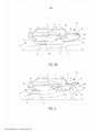
[0037] A Figura 1 apresenta esquematicamente um corte meridional de um estator e de um rotor de acordo com uma modalidade da invenção quando o rotor está em posição de funcionamento em uma turbomáquina.[0037] Figure 1 schematically shows a southern section of a stator and a rotor according to an embodiment of the invention when the rotor is in operating position in a turbomachine.
[0038] A Figura 2a apresenta esquematicamente um corte meridional do estator e do rotor da Figura 1, em posição isolada e prontos para serem montados.[0038] Figure 2a schematically shows a southern section of the stator and rotor of Figure 1, in an isolated position and ready to be assembled.
[0039] A Figura 2b apresenta esquematicamente um corte meridional de um estator de um rotor de acordo com uma modalidade da invenção, em posição isolada e prontos para serem montados.[0039] Figure 2b schematically shows a southern section of a rotor stator according to an embodiment of the invention, in an isolated position and ready to be assembled.
[0040] A Figura 3 apresenta esquematicamente um corte meridional do estator e do rotor da Figura 1, em uma posição intermediária de teste.[0040] Figure 3 schematically shows a southern section of the stator and rotor of Figure 1, in an intermediate test position.
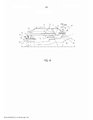
[0041] A Figura 4 apresenta esquematicamente um corte meridional de um estator e de um rotor de acordo com uma modalidade da invenção quando o rotor está em uma posição de funcionamento em uma turbomáquina.[0041] Figure 4 schematically shows a meridional section of a stator and a rotor according to an embodiment of the invention when the rotor is in an operating position in a turbomachine.
[0042] A Figura 1 representa um eixo 1 de uma turbomáquina móvel em rotação em torno de um eixo LL, instalado em posição de funcionamento em um cárter 2, no nível de um rolamento 3 de guia do eixo 1 na turbomáquina.[0042] Figure 1 represents an axis 1 of a mobile turbomachine rotating around an axis LL, installed in operating position in a
[0043] Na Figura 1 e nas seguintes, o fluxo principal dos gases na turbomáquina segue da esquerda para a direita. Os elementos representados no exemplo correspondente às figuras se encontram em uma parte da turbomáquina cercado por este fluxo principal. Na sequência da descrição, os termos à montante e à jusante são entendidos em relação a esse fluxo principal.[0043] In Figure 1 and the following, the main flow of gases in the turbomachine goes from left to right. The elements represented in the example corresponding to the figures are found in a part of the turbomachine surrounded by this main flow. Following the description, the upstream and downstream terms are understood in relation to that main stream.
[0044] O rolamento 3 de guia é formato, notadamente, por um anel externo 4, fixado ao cárter 2, e um anel interno 5, fixado ao eixo 1, entre os quais rolos 6 podem rolar livremente. O rolamento 3 é projetado de modo que os rolos 6 se mantenham no anel interno 5 quando o eixo 1 é deslocado para fora de sua posição de funcionamento, pelas operações de montagem ou de desmontagem. Outros rolamentos podem ser usados além dos rolos, como, por exemplo, bilhas. Pode-se, ainda, considerar o projeto de um rolamento 3, ilustrado na Figura 2b, cujos rolos 6 são mantidos ao lado do anel externo 4 quando se desmonta o eixo 1 rotatório.[0044] The
[0045] O anel externo 4 é ligado ao cárter 2 por uma peça 7 de suporte do rolamento 3. O anel interno 5 é, em geral, fixado à superfície do eixo rotatório 1.[0045] The outer ring 4 is connected to the
[0046] O cárter 2 e o eixo rotatório 1 são arranjados para formar um invólucro 8 de lubrificação 4 em torno do rolamento 3. Esse invólucro 8 inclui uma passagem do eixo 1 à montante do rolamento 3 e uma passagem do eixo 1 à jusante do rolamento 3.[0046] The
[0047] O invólucro 8 de lubrificação faz parte do circuito de lubrificação da turbomáquina. O óleo entra no invólucro 8 por um orifício de entrada, não representado na figura, depois é dirigido na direção do rolamento 3 para lhe lubrificar. O óleo, tendo lubrificado o rolamento 3, sai deste sendo projetado em diferentes direções. O invólucro 8 possui, notadamente, como função recuperar esse óleo para que ele saia por um orifício de saída, não representado igualmente na figura, de modo a lhe reenviar na direção do circuito de lubrificação.[0047]
[0048] Para evitar as perdas de óleos, as passagens do eixo 1 dentro do invólucro 8 são equipadas com meios radiais de vedação 9, 10, aptos, notadamente, a bloquear o óleo. Ainda, notadamente em vista de melhoria da vedação desses meios radiais de vedação 9, 10, quando da rotação do eixo 1, o elemento é projetado para que a pressão P0 do invólucro 8 seja inferior às pressões P1, P2 que se encontram no exterior das passagens do eixo 1, quando a turbomáquina funciona. Essa despressurização participa da vedação do invólucro 8.[0048] In order to avoid oil leakage, the shaft passages 1 inside the
[0049] Para obter esse resultado, o meio radial de vedação 9 da passagem à montante inclui, aqui, uma junta radial de vedação segmentada 11 (JRS), constituída por um anel de vedação de segmentos de carbono mantidos chapados uns contra os outros, solidários ao cárter 2. Essa junta radial de vedação segmentada 11 coopera com uma superfície cilíndrica 12 que entra em contato com sua superfície interna. A superfície cilíndrica 12 é montada em uma luva 13 solidária ao eixo rotatório 1, cuja seção em um plano meridional possui um formato de U paralelo ao eixo de rotação LL. Esse formato permite uma elasticidade suficiente para que o eixo 1 possa ser instalado no cárter 2 indo, aqui, da direita para a esquerda seguindo o eixo de rotação LL e, depois, para que a junta radial segmentada 11 e a superfície cilíndrica 12 estejam apoiadas quando o eixo 1 está na posição de funcionamento em relação ao cárter 2.[0049] To obtain this result, the radial sealing means 9 of the upstream passage includes, here, a segmented radial sealing gasket 11 (JRS), constituted by a sealing ring of carbon segments kept flat against each other, fixed to the
[0050] O projeto da junta radial segmentada 11 permite uma vedação suficiente para frear a passagem do ar e estabelecer, assim, uma diferença de pressão entre seus dois lados. Dessa forma, quando a turbomáquina funciona, a pressão P0 do invólucro 8 pode ser mantida a um valor inferior ao da pressão P1 que se estabelece no espaço à montante do meio radial de vedação 9 da passagem à montante, que está em comunicação com as regiões de pressão mais elevadas na turbomáquina.[0050] The design of the segmented radial joint 11 allows a seal sufficient to stop the passage of air and thus establish a pressure difference between its two sides. In this way, when the turbomachine works, the pressure P0 of the
[0051] O meio radial de vedação 9 é completado por uma verruma 14, no interior do invólucro 8 em relação à junta radial segmentada 11. Essa verruma 14 coopera com uma parte da superfície cilíndrica 12 que se estende à jusante desta, cooperando com a junta radial segmentada 11. A verruma 14 possui como função enviar para o invólucro 8 o óleo que pode chegar até a passagem à montante e proteger a junta radial segmentada 11 desse óleo.[0051] The radial sealing means 9 is completed by an
[0052] O meio radial de vedação 10 da passagem à jusante do eixo rotatório 1 inclui uma junta labirinto, constituída de linguetas 15 solidárias ao eixo 1, que encontram uma superfície cilíndrica 16 solidária ao cárter 2, em material abrasível. Essa junta labirinto 15, 16, permite uma boa vedação à passagem do óleo.[0052] The radial sealing means 10 of the passage downstream of the rotating shaft 1 includes a labyrinth joint, made up of
[0053] A junta labirinto 15, 16 não é tão eficaz quando a junta radial segmentada 11, 12 para estabelecer uma diferença de pressão dos gases entre suas extremidades. No entanto, no exemplo apresentado, o fluxo dos gases em torno do invólucro 8 de lubrificação é feito da esquerda para a direita e a junta radial segmentada 11 bloqueia o fluxo do ar à montante, isso é suficiente para que a pressão P0 no invólucro 8 se mantenha igualmente inferior à pressão P2 que se estabelece no espaço à jusante da junta labirinto 15, 16.[0053] The labyrinth joint 15, 16 is not as effective as the segmented radial joint 11, 12 in establishing a difference in gas pressure between its ends. However, in the example shown, the flow of gases around the
[0054] O meio radial de vedação 10 da passagem à jusante é, aqui, igualmente completado por uma verruma 17, situada à montante da junta labirinto 15, 16. Essa verruma 17 coopera com um anel 18 que se estende à montante da superfície cilíndrica 16 da junta labirinto. A verruma 17 possui como função enviar para o invólucro 8 o óleo que pode chegar até a passagem à jusante e proteger a junta labirinto 15, 16 desse óleo.[0054] The radial sealing means 10 of the downstream passage is here also completed by an
[0055] O anel 18 que coopera com a verruma 17 é significativamente alinhado ao suporte das linguetas 15 da junta labirinto. O elemento é sustentado por uma flange 19 que se estende a partir do eixo rotatório 1.[0055] The
[0056] De acordo com um aspecto da invenção, a flange 19 se estende radialmente de tal forma que o diâmetro do anel 18 que coopera com a verruma seja levemente superior àquele do anel externo 4 do rolamento 3.[0056] According to one aspect of the invention, the
[0057] Ainda, em referência à Figura 2a, em uma modalidade em que os rolos 6 do rolamento 3 deslizam sobre o anel externo 4, a extensão na direção à jusante do anel externo 4 do rolamento e a extensão na direção à montante do anel 18 que coopera com a verruma 17 são arranjadas de tal forma aqui que o anel 18 da verruma 17 cobre parcialmente o anel externo 4 do rolamento 3.[0057] Still, referring to Figure 2a, in an embodiment in which the
[0058] Essa disposição faz com que não haja caminho direto entre o rolamento 3 e a verruma 17 da passagem à jusante. As projeções de óleo, representadas por uma seta na Figura 1, são, assim, paradas pelo anel. Isso permite que haja uma configuração compacta à jusante do rolamento 3, em que o meio radial de vedação 10 da passagem à jusante está próximo ao rolamento 3, mas onde a verruma 17 está protegida das projeções de óleo.[0058] This arrangement means that there is no direct path between
[0059] Na alternativa representada, com o eixo 1 e o cárter na posição desencaixada na Figura 2b, é possível considerar que não seja o anel externo 4 do rolamento 3 que se estende sob o anel 18 da verruma 17, mas uma parte 7b da peça 7 de suporte do rolamento 3. Essa parte 7b do suporte do rolamento não possui função de pista para os rolos 6, mas forma, então, uma tampa que cobre radialmente o rolamento 3 do lado à jusante e que pode passar para o interior do anel 18 da verruma 17 quando o eixo 1 está em posição de funcionamento.[0059] In the alternative represented, with the shaft 1 and the housing in the disengaged position in Figure 2b, it is possible to consider that it is not the outer ring 4 of the
[0060] De acordo com outro aspecto da invenção, o eixo rotativo 1 está instalado no cárter 2, estando transladado seguindo o eixo de rotação LL. Nos exemplos apresentados, em referência às Figuras 2a e 2b, o eixo 1 em posição desencaixada se encontra à jusante do cárter 2 e a montagem se faz seguindo uma direção que vai da jusante à montante para o rotor.[0060] According to another aspect of the invention, the rotary axis 1 is installed in the
[0061] A Figura 2a representa a montagem do eixo logo antes do acoplamento para a modalidade da Figura 1. O alongamento do anel externo 4 do rolamento 3 é tal que os rolos 6, solidários ao eixo 1, entram em contato com ele antes que a extremidade à montante da superfície cilíndrica 12 que coopera com a junta radial segmentada 11 encontre a parte à jusante da verruma 14 da passagem à montante.[0061] Figure 2a represents the assembly of the shaft just before the coupling for the modality of Figure 1. The elongation of the outer ring 4 of the
[0062] Isso corresponde, em referência à Figura 1, ao fato de que, quando o eixo 1 está instalado em posição de funcionamento, a distância d1 que separa a extremidade à jusante do anel externo 4 da extremidade à montante dos rolos 6 do rolamento 3 é superior à distância d2 que separa a extremidade à montante da superfície cilíndrica 12 da extremidade à jusante da verruma 14, para o meio radial de vedação à montante 9.[0062] This corresponds, with reference to Figure 1, to the fact that when shaft 1 is installed in operating position, the distance d1 that separates the downstream end of the outer ring 4 from the upstream end of the
[0063] Dessa forma, as partes do meio radial de vedação 9 da passagem à montante do eixo 1 se acoplam àquelas do cárter 3, enquanto os rolos 6 do rolamento 3 já estão engajados no anel externo 4 do rolamento. Os movimentos do eixo 1 na translação para a montagem são, portanto, guiados pelo rolamento 3, o que limita os riscos de choque com o acoplamento ou os esforços parasitas quando da instalação no meio radial de vedação 9.[0063] In this way, the parts of the radial sealing means 9 of the upstream passage of the shaft 1 couple to those of the
[0064] Em uma variante, pode-se simplesmente proteger a junta radial segmentada 11, que é o mais frágil. Nesse caso, a distância d1 que separa a extremidade à jusante do anel externo 4 da extremidade à montante dos rolos 6 do rolamento 3 é superior à distância d3, que separa a extremidade à montante da superfície cilíndrica 12 da extremidade à jusante da junta radial segmentada 11.[0064] In a variant, one can simply protect the segmented radial joint 11, which is the most fragile. In this case, the distance d1 separating the downstream end of the outer ring 4 from the upstream end of the
[0065] Pode-se notar, também, que, nessa configuração, as necessidades de extensão do anel externo 4 na direção à jusante coincidem para a função de montagem da junta radial segmentada 11 e para a função de proteção da verruma 17 das projeções de óleo que vêm do rolamento 3.[0065] It can also be noted that, in this configuration, the extension needs of the outer ring 4 in the downstream direction coincide for the assembly function of the segmented radial joint 11 and for the protection function of the
[0066] Em uma modalidade preferida, em referência à Figura 1 e à Figura 2a, os rolos 6 ligados ao eixo 1 se acoplam igualmente com o anel externo 4, antes que o anel 18 que coopera com a verruma 17 à jusante encontre a superfície cilíndrica 16 que coopera com as linguetas 15 da junta labirinto. Isso permite, também, proteger de choques o meio radial de vedação 10 da passagem à jusante quando da montagem.[0066] In a preferred embodiment, referring to Figure 1 and Figure 2a, the
[0067] Em uma variante de modalidade, representada na Figura 2b, os rolos 6 são solidários ao anel externo 4, fixado ao cárter 2. Nesse caso, é o anel interno 5 que possui uma extensão na direção à montante, para além do lugar em que se efetua o rolo quando o eixo 1 está em posição de funcionamento. Essa extensão é tal que o anel interno 5 encontra os rolos 6 antes que as partes solidárias do cárter 2 e do eixo 2 dos meios radiais de vedação 9, 10 se encontrem.[0067] In a variant of the modality, represented in Figure 2b, the
[0068] De acordo com ainda outro aspecto da invenção, em referência à Figura 3, uma junta de vedação em pressão 20 é instalada em um anel 21 à jusante da superfície cilíndrica 16 que coopera com as linguetas 15 da junta labirinto. O eixo 1 e o cárter 2 são configurados para que essa junta de vedação em pressão 20 se apoie contra um anel 22, solidário ao eixo 1 e que prolonga a junta labirinto 15 quando o eixo 1 está em uma posição determinada, deslocada da posição de funcionamento, como ilustrado na Figura 3.[0068] According to yet another aspect of the invention, referring to Figure 3, a
[0069] A junta de vedação em pressão 20 é, aqui, uma junta PTFE, significando politetrafluoretileno, que inclui um anel composto por esse material e preso por uma mola circular que lhe pressiona contra o anel 22 do eixo 1. Esse tipo de junta permite garantir uma boa vedação à pressão com atritos fracos. Ainda, essas juntas resistem a temperaturas elevadas, que podem se encontrar nesse local em uma turbomáquina em funcionamento.[0069] The
[0070] Pode-se, no entanto, considerar o uso de juntas formadas por outros materiais, com a condição de que permitam garantir uma vedação em pressão em torno do eixo com sua passagem através do invólucro e que suportem as condições de entorno de uma turbomáquina. Por outro lado, como se verá na seguida nas condições de utilização, não é necessário que funcionem com um atrito fraco quando o eixo 1 está em rotação.[0070] It is possible, however, to consider the use of gaskets formed by other materials, on condition that they allow to guarantee a pressure seal around the axis with its passage through the casing and that withstand the conditions surrounding a turbomachine. On the other hand, as will be seen below in the conditions of use, it is not necessary for them to operate with low friction when the axis 1 is rotating.
[0071] Na Figura 3, o eixo 1 e o cárter 2 já apresentados nas Figuras 1 e 2a estão em uma configuração em que o eixo está transladado em uma posição intermediária, o eixo estando deslocado por uma distância d4 na direção à jusante em relação à posição de funcionamento da Figura 1.[0071] In Figure 3, shaft 1 and
[0072] Essa distância d4 corresponde, na Figura 1, a um deslocamento da junta PTFE 20 em relação à sua posição de apoio no anel 22, de tal modo que ela se encontra desengajada desse anel 22 quando o eixo 1 está em posição de funcionamento.[0072] This distance d4 corresponds, in Figure 1, to a displacement of the
[0073] Dessa forma, quando o eixo 1 está em posição de funcionamento, como pode-se ver na Figura 1, a junta PTFE 20 está desengajada do anel 22. No exemplo apresentado, essa junta 20 não está, portanto, ativa quando o eixo 1 está em posição de funcionamento e os meios 21, 22, com os quais ele coopera, não interagem juntos ou com outros elementos da turbomáquina quando o eixo 1 está em posição de funcionamento. Esses meios 20, 21, 22 não introduzem, portanto, atrito ou perturbação quando a turbomáquina funciona. Ainda, no exemplo, estando no exterior do invólucro 8, os meios 20, 21, 22 não correm risco de serem poluídos pelas projeções de óleo do rolamento 3.[0073] Thus, when the shaft 1 is in operating position, as can be seen in Figure 1, the PTFE joint 20 is disengaged from the
[0074] Ainda, a distância d4 de translação para a posição intermediária é inferior à distância d1 anteriormente descrita na Figura 1, necessária para desengajar os rolos 6 do rolamento 3 do anel externo 4. Passa-se, portanto, da posição de funcionamento para a posição intermediária, e inversamente, efetuando uma translação do eixo 1 em relação ao cárter 2 que segue o eixo de rotação LL, o eixo 1 sendo guiado pelo contato dos rolos 6 do rolamento 3 com os anéis interno 5 e externo 4.[0074] Also, the distance d4 of translation to the intermediate position is smaller than the distance d1 previously described in Figure 1, necessary to disengage the
[0075] Ainda, em referência à Figura 2a ou 2b, a junta PTFE 20 e seu anel 21 suportam, preferencialmente, um diâmetro ligeiramente superior àquele das partes 18, 15 solidárias ao eixo 1 do meio radial de vedação 10, para a passagem à jusante. Pode-se, portanto, efetuar a instalação do eixo 1 no cárter 2 sem que a junta PTFE 20 atrite contra esses elementos 18, 15.[0075] Still, referring to Figure 2a or 2b, the
[0076] De outro lado, no nível do meio de vedação radial à montante 9, a superfície cilíndrica 12 está, aqui, aumentada na direção à montante por um valor ao menos igual à distância d4 de deslocamento entre a posição de funcionamento e a posição intermediária.[0076] On the other hand, at the level of the upstream radial sealing means 9, the
[0077] Dessa forma, como se pode ver na Figura 3, quando o eixo está em posição intermediária, a junta radial segmentada 11 coopera com a superfície cilíndrica 12 e a junta PTFE 20 coopera com o anel 22 de tal forma que uma vedação em pressão é garantida ao mesmo tempo às duas passagens do eixo 1 no invólucro de lubrificação 8.[0077] In this way, as can be seen in Figure 3, when the shaft is in an intermediate position, the segmented
[0078] Essa posição intermediária define vantajosamente uma posição de teste para a junta radial segmentada 11. De fato, a junta radial segmentada 11, por se encontrar na passagem à montante do eixo 1, torna-se inacessível quando este está instalado no cárter 2. É, portanto, impossível efetuar os controles diretos para verificar seu estado.[0078] This intermediate position advantageously defines a test position for the segmented radial joint 11. In fact, the segmented radial joint 11, as it is located in the upstream passage of the shaft 1, becomes inaccessible when the latter is installed in the
[0079] Em uma variante de modalidade, ilustrada na Figura 4, a posição de teste é a mesma que a posição de funcionamento. Nessa variante, uma junta em anel 23b é inserida em um pescoço 23b arranjado em uma parte da superfície cilíndrica 18 do rotor que coopera com a verruma 17 sobre o estator. Essa junta em anel 23b se apoia, nessa posição, contra a superfície cilíndrica 16 do estator que coopera com o labirinto 15 do estator, de modo a garantir uma vedação em pressão quando o rotor não gira mais.[0079] In a variant of the modality, illustrated in Figure 4, the test position is the same as the operating position. In this variant, a
[0080] A junta em anel 23b é produzida, aqui, em material, por exemplo, cera de abelha, que se funde sob o efeito do calor provocado pelos atritos quando o rotor é posto em rotação, quando de suas condições de funcionamento. Dessa forma, ela se elimina quando a turbomáquina funciona e não cria perdas por atrito.[0080] The
[0081] Com a configuração ilustrada na Figura 3, o método de montagem pode ser vantajosamente completado por um método de teste.[0081] With the configuration illustrated in Figure 3, the assembly method can be advantageously completed by a test method.
[0082] Para tanto, após ter realizado o acoplamento dos rolos 6 e do anel correspondente 4 do rolamento 3, uma primeira etapa consiste em continuar a translação do eixo 1 na direção à montante até a posição intermediária.[0082] For that, after having carried out the coupling of the
[0083] Nessa posição, a junta PTFE 20 garante a vedação em pressão à passagem à jusante do eixo 1 no invólucro de lubrificação 8. Por outro lado, se a junta radial segmentada 11 funciona corretamente, ela garante a vedação em pressão à passagem à montante, cooperando com a extensão prevista para tanto da superfície cilíndrica 12 solidária ao eixo 1.[0083] In this position, the
[0084] Pode-se, portanto, efetuar uma etapa de teste nessa posição, utilizando, por exemplo, os orifícios de passagem do óleo pelo invólucro de lubrificação 8 para aspirar e criar uma depressão no invólucro 8. A observação da evolução da pressão no invólucro de lubrificação 8 informa, portanto, sobre o estado da junta radial segmentada 11. Se ela foi deteriorada, por exemplo, quando do encontro com a superfície cilíndrica 12, ela deixará fugas significativas que farão com que a pressão rapidamente se recupere.[0084] It is therefore possible to carry out a test step in this position, using, for example, the oil passage holes through the
[0085] Se o teste de despressurização mostra, no entanto, que a junta radial segmentada 11 está em bom estado, a etapa seguinte consiste em seguir a translação do eixo 1 na direção à montante para lhe levar à sua posição de funcionamento no cárter 2.[0085] If, however, the depressurization test shows that the segmented radial joint 11 is in good condition, the next step is to follow the translation of shaft 1 in the upstream direction to bring it to its operating position in the
[0086] Vantajosamente, as partes da superfície cilíndrica 12, solidária ao eixo 1, cooperam com a junta radial segmentada 11 em posição de funcionamento e em posição intermediária, de teste, formando uma única face contínua. Dessa forma, quando o eixo 1 é transladado de uma posição à outra, a junta radial segmentada 11 se mantém em contato com esta face. Não há, portanto, risco de deterioração da junta 11 pelos choque com o encontro de faces diferentes.[0086] Advantageously, the parts of the
[0087] Em uma variante, o teste da junta radial segmentada 11 pode ser feito após um período de funcionamento da turbomáquina. Nesse caso, a primeira etapa consiste em deslocar o eixo 1 na direção à jusante da distância d4 para lhe fazer passar da posição de funcionamento para a posição intermediária, de teste, e, depois, efetuar o teste de despressurização. Se o teste é conclusivo, pode-se substituir o eixo 1 em sua posição de funcionamento sem ser obrigado a lhe desmontar completamente do cárter 2.[0087] In one variant, the segmented radial
[0088] Com a variante de modalidade correspondente à Figura 4, a primeira etapa do método de teste de montagem consiste em, após ter realizado o acoplamento dos rolos 6 e do anel correspondente 4 do rolamento 3, continuar a translação do eixo 1 na direção à montante até a posição de funcionamento, que é igualmente a posição de teste. Durante essa etapa, o material da junta em anel 23a pode se deformar para deslizar contra a superfície cilíndrica 17, ao mesmo tempo em que se mantém em posição sobre o rotor 1 pelo pescoço 23b.[0088] With the modality variant corresponding to Figure 4, the first step of the assembly test method consists of, after having carried out the coupling of the
[0089] Em seguida, o rotor sendo mantido imóvel, pode-se efetuar as mesmas etapas que na variante anterior para efetuar o teste da junta radial de vedação, a junta em anel 23a garantindo a vedação no outro extremo por pressão contra a superfície cilíndrica 17. No entanto, não há etapa de translação após o teste, uma vez que o rotor já está em sua posição de funcionamento.[0089] Then, the rotor being held still, the same steps can be carried out as in the previous variant to test the radial sealing gasket, the
[0090] Em seguida, em uma etapa ulterior, quando a turbomáquina está montado, a junta em anel 23a, feita, aqui, de cera de abelha, se funde quando do primeiro funcionamento da turbomáquina e desaparece. Seu desaparecimento faz com que não haja mais contato neste local entre o rotor e o estator, e que, portanto, as perdas por atrito sejam nulas ali.[0090] Then, in a further step, when the turbomachine is assembled, the
[0091] A vantagem dessa variante é que não é necessário projetar uma extensão radial complementar da superfície cilíndrica 12 para que a junta radial de vedação 11 esteja ativa durante o método de teste de montagem. O conjunto pode, portanto, ser mais compacto.[0091] The advantage of this variant is that it is not necessary to design a complementary radial extension of the
Claims (11)
Applications Claiming Priority (3)
| Application Number | Priority Date | Filing Date | Title |
|---|---|---|---|
| FR1457350A FR3024492B1 (en) | 2014-07-29 | 2014-07-29 | ELEMENT COMPRISING A STATOR AND A TURBOMACHINE ROTOR WITH A SEAL AND TESTING THIS SEAL |
| FR1457350 | 2014-07-29 | ||
| PCT/FR2015/052004 WO2016016545A1 (en) | 2014-07-29 | 2015-07-21 | Turbomachine element comprising an auxiliary sealing means, and method for testing this element |
Publications (2)
| Publication Number | Publication Date |
|---|---|
| BR112016029958A2 BR112016029958A2 (en) | 2017-08-22 |
| BR112016029958B1 true BR112016029958B1 (en) | 2022-08-30 |
Family
ID=51726749
Family Applications (1)
| Application Number | Title | Priority Date | Filing Date |
|---|---|---|---|
| BR112016029958-2A BR112016029958B1 (en) | 2014-07-29 | 2015-07-21 | TURBOMACHINE ELEMENT, TURBOMACHINE, AND TEST METHOD |
Country Status (9)
| Country | Link |
|---|---|
| US (1) | US10502083B2 (en) |
| EP (1) | EP3175091B1 (en) |
| JP (1) | JP6499211B2 (en) |
| CN (1) | CN106661942B (en) |
| BR (1) | BR112016029958B1 (en) |
| CA (1) | CA2952928C (en) |
| FR (1) | FR3024492B1 (en) |
| RU (1) | RU2682301C2 (en) |
| WO (1) | WO2016016545A1 (en) |
Families Citing this family (8)
| Publication number | Priority date | Publication date | Assignee | Title |
|---|---|---|---|---|
| US9976561B2 (en) * | 2016-04-11 | 2018-05-22 | Borgwarner Inc. | Method for securing stator in high speed electric motors |
| FR3062679B1 (en) * | 2017-02-07 | 2019-04-19 | Safran Aircraft Engines | VIROLE FOR REDUCING THE PRESSURE REDUCTION IN THE NEIGHBORHOOD OF THE UPPER JOINT OF A TURBOJET ENGINE BEARING ENCLOSURE |
| FR3067057B1 (en) * | 2017-05-30 | 2020-01-10 | Safran Aircraft Engines | TURBOMACHINE COMPRISING AN OPTIMIZED LEAKAGE FLOW ENCLOSURE |
| US10458267B2 (en) * | 2017-09-20 | 2019-10-29 | General Electric Company | Seal assembly for counter rotating turbine assembly |
| FR3085433B1 (en) * | 2018-08-28 | 2020-08-07 | Safran Aircraft Engines | TURBOMACHINE WITH AXIAL EFFORT TAKE-UP AT BLOWER LEVEL BY SUPPLY OF GAS UNDER PRESSURE |
| US11280208B2 (en) * | 2019-08-14 | 2022-03-22 | Pratt & Whitney Canada Corp. | Labyrinth seal assembly |
| FR3122493B1 (en) * | 2021-04-30 | 2023-03-17 | Safran Aircraft Engines | LEAK TEST DEVICE PROVIDED WITH A SYSTEM FOR CONTINUOUSLY ADJUSTING THE CLEARANCE BETWEEN TWO ELEMENTS OF A LABYRINTH SEAL |
| US11719120B2 (en) * | 2021-12-27 | 2023-08-08 | Pratt & Whitney Canada Corp. | Vacuum testing a seal within a gas turbine engine structure |
Family Cites Families (17)
| Publication number | Priority date | Publication date | Assignee | Title |
|---|---|---|---|---|
| FR1260598A (en) | 1960-01-30 | 1961-05-12 | Filter paper for filtering coffee, tea or the like | |
| FR2644843B1 (en) * | 1989-03-23 | 1991-05-24 | Snecma | METHOD FOR MOUNTING THE LOW PRESSURE TURBINE ON THE HIGH PRESSURE BODY OF A TURBOMACHINE WITH INTER-SHAFT BEARING AND TOOLS FOR IMPLEMENTING THE PROCESS |
| FR2705733B1 (en) * | 1993-05-25 | 1995-06-30 | Snecma | Device for depressurizing the lubrication chambers surrounding the bearings of a turbomachine. |
| US5975537A (en) * | 1997-07-01 | 1999-11-02 | General Electric Company | Rotor and stator assembly configured as an aspirating face seal |
| US6203273B1 (en) * | 1998-12-22 | 2001-03-20 | United Technologies Corporation | Rotary machine |
| GB2359863B (en) * | 2000-03-04 | 2003-03-26 | Alstom | Turbocharger |
| US6966622B2 (en) | 2001-09-28 | 2005-11-22 | Hewlett-Packard Development Company, L.P. | Thermal sense resistor for a replaceable printer component |
| US6887038B2 (en) * | 2003-09-02 | 2005-05-03 | General Electric Company | Methods and apparatus to facilitate sealing between rotating turbine shafts |
| FR2867229B1 (en) | 2004-03-05 | 2006-07-28 | Snecma Moteurs | TURBOMACHINE BEARING BEARING WITH REDUCED SIZE |
| FR2890110B1 (en) * | 2005-08-26 | 2007-11-02 | Snecma | METHOD FOR ASSEMBLING A TURBOMACHINE |
| EP1777417B1 (en) * | 2005-10-24 | 2008-06-11 | BorgWarner Inc. | Turbocharger |
| US7360434B1 (en) * | 2005-12-31 | 2008-04-22 | Florida Turbine Technologies, Inc. | Apparatus and method to measure air pressure within a turbine airfoil |
| DE102006052786B4 (en) * | 2006-11-09 | 2011-06-30 | MTU Aero Engines GmbH, 80995 | turbomachinery |
| US20130106061A1 (en) * | 2011-10-28 | 2013-05-02 | General Electric Company | High temperature seal system |
| FR2983908B1 (en) | 2011-12-08 | 2015-02-20 | Snecma | SYSTEM FOR ENSURING SEALING BETWEEN AN OIL ENCLOSURE AND AN OUTER VOLUME ATTACHED AND TURBOMACHINE EQUIPPED WITH SUCH A SEALING SYSTEM. |
| US9353647B2 (en) * | 2012-04-27 | 2016-05-31 | General Electric Company | Wide discourager tooth |
| FR2993024B1 (en) * | 2012-07-06 | 2014-08-08 | Snecma | TURBOMACHINE BEARING SEAL SEAL DEVICE WITH TWO ELASTIC JOINTS |
-
2014
- 2014-07-29 FR FR1457350A patent/FR3024492B1/en active Active
-
2015
- 2015-07-21 BR BR112016029958-2A patent/BR112016029958B1/en active IP Right Grant
- 2015-07-21 US US15/320,937 patent/US10502083B2/en active Active
- 2015-07-21 CN CN201580033678.2A patent/CN106661942B/en active Active
- 2015-07-21 JP JP2016574252A patent/JP6499211B2/en active Active
- 2015-07-21 CA CA2952928A patent/CA2952928C/en active Active
- 2015-07-21 RU RU2016150381A patent/RU2682301C2/en active
- 2015-07-21 WO PCT/FR2015/052004 patent/WO2016016545A1/en active Application Filing
- 2015-07-21 EP EP15751051.2A patent/EP3175091B1/en active Active
Also Published As
| Publication number | Publication date |
|---|---|
| EP3175091A1 (en) | 2017-06-07 |
| RU2016150381A3 (en) | 2019-01-14 |
| US20170152754A1 (en) | 2017-06-01 |
| JP2017530283A (en) | 2017-10-12 |
| WO2016016545A1 (en) | 2016-02-04 |
| RU2682301C2 (en) | 2019-03-18 |
| CN106661942A (en) | 2017-05-10 |
| CA2952928C (en) | 2022-05-31 |
| US10502083B2 (en) | 2019-12-10 |
| EP3175091B1 (en) | 2018-10-31 |
| CN106661942B (en) | 2018-10-09 |
| JP6499211B2 (en) | 2019-04-10 |
| FR3024492B1 (en) | 2019-08-23 |
| BR112016029958A2 (en) | 2017-08-22 |
| FR3024492A1 (en) | 2016-02-05 |
| RU2016150381A (en) | 2018-08-28 |
| CA2952928A1 (en) | 2016-02-04 |
Similar Documents
| Publication | Publication Date | Title |
|---|---|---|
| BR112016029958B1 (en) | TURBOMACHINE ELEMENT, TURBOMACHINE, AND TEST METHOD | |
| WO2016058457A1 (en) | Bushing for cooling dual-side mechanical seal friction pair and centrifugal pump cooling system thereof | |
| US8047769B2 (en) | Inspection port plug devices | |
| JP5974163B2 (en) | Pipe-integrated pulley pulley metal seal half | |
| JP4751172B2 (en) | Apparatus for lubricating components in turbomachinery | |
| KR101604939B1 (en) | Gas turbine | |
| JP2006125398A5 (en) | ||
| BR102016009341A2 (en) | gas turbine engine and gas turbine | |
| CN104864100B (en) | Refrigerant condenser combination sealing system | |
| BR112014013673B1 (en) | TURBINE ENGINE INCLUDING OIL CHAMBER | |
| US20170307019A1 (en) | Seal Assembly For A Turbomachine | |
| WO2017145581A1 (en) | Impeller back surface cooling structure and supercharger | |
| JP2010121463A (en) | Gas seal structure of centrifugal compressor with built-in speed increaser | |
| KR20180113465A (en) | Turbocharger | |
| JP2005163641A (en) | Turbocharger | |
| CN103573416B (en) | Sealing member | |
| JP6033476B2 (en) | Axial expander | |
| CA2964088A1 (en) | Sealing device for seal runner face | |
| US20070296157A1 (en) | Bearing seal | |
| US10851664B2 (en) | Sealing assembly for a gas turbine engine | |
| US9416679B2 (en) | Borescope assembly and method of installing borescope plugs | |
| BR102015028560A2 (en) | enclosure deflector system and gas turbine engine | |
| JP2012112359A (en) | Bearing stand cover of axial-flow exhaust turbine and axial-flow exhaust turbine | |
| CN104329467B (en) | S-shaped multiple labyrinth seal device | |
| CN104329468B (en) | A kind of two-way floating sealing device |
Legal Events
| Date | Code | Title | Description |
|---|---|---|---|
| B06U | Preliminary requirement: requests with searches performed by other patent offices: procedure suspended [chapter 6.21 patent gazette] | ||
| B09A | Decision: intention to grant [chapter 9.1 patent gazette] | ||
| B16A | Patent or certificate of addition of invention granted [chapter 16.1 patent gazette] |
Free format text: PRAZO DE VALIDADE: 20 (VINTE) ANOS CONTADOS A PARTIR DE 21/07/2015, OBSERVADAS AS CONDICOES LEGAIS |