BR112016025708B1 - STEERING COLUMN FOR A MOTOR VEHICLE, AND METHOD FOR ASSEMBLY OF A STEERING COLUMN FOR A MOTOR VEHICLE - Google Patents
STEERING COLUMN FOR A MOTOR VEHICLE, AND METHOD FOR ASSEMBLY OF A STEERING COLUMN FOR A MOTOR VEHICLE Download PDFInfo
- Publication number
- BR112016025708B1 BR112016025708B1 BR112016025708-1A BR112016025708A BR112016025708B1 BR 112016025708 B1 BR112016025708 B1 BR 112016025708B1 BR 112016025708 A BR112016025708 A BR 112016025708A BR 112016025708 B1 BR112016025708 B1 BR 112016025708B1
- Authority
- BR
- Brazil
- Prior art keywords
- steering column
- clamp
- bearing
- column sleeve
- flexible edge
- Prior art date
Links
Images

Classifications
-
- B—PERFORMING OPERATIONS; TRANSPORTING
- B62—LAND VEHICLES FOR TRAVELLING OTHERWISE THAN ON RAILS
- B62D—MOTOR VEHICLES; TRAILERS
- B62D1/00—Steering controls, i.e. means for initiating a change of direction of the vehicle
- B62D1/02—Steering controls, i.e. means for initiating a change of direction of the vehicle vehicle-mounted
- B62D1/16—Steering columns
-
- F—MECHANICAL ENGINEERING; LIGHTING; HEATING; WEAPONS; BLASTING
- F16—ENGINEERING ELEMENTS AND UNITS; GENERAL MEASURES FOR PRODUCING AND MAINTAINING EFFECTIVE FUNCTIONING OF MACHINES OR INSTALLATIONS; THERMAL INSULATION IN GENERAL
- F16C—SHAFTS; FLEXIBLE SHAFTS; ELEMENTS OR CRANKSHAFT MECHANISMS; ROTARY BODIES OTHER THAN GEARING ELEMENTS; BEARINGS
- F16C19/00—Bearings with rolling contact, for exclusively rotary movement
- F16C19/02—Bearings with rolling contact, for exclusively rotary movement with bearing balls essentially of the same size in one or more circular rows
- F16C19/04—Bearings with rolling contact, for exclusively rotary movement with bearing balls essentially of the same size in one or more circular rows for radial load mainly
- F16C19/06—Bearings with rolling contact, for exclusively rotary movement with bearing balls essentially of the same size in one or more circular rows for radial load mainly with a single row or balls
-
- F—MECHANICAL ENGINEERING; LIGHTING; HEATING; WEAPONS; BLASTING
- F16—ENGINEERING ELEMENTS AND UNITS; GENERAL MEASURES FOR PRODUCING AND MAINTAINING EFFECTIVE FUNCTIONING OF MACHINES OR INSTALLATIONS; THERMAL INSULATION IN GENERAL
- F16C—SHAFTS; FLEXIBLE SHAFTS; ELEMENTS OR CRANKSHAFT MECHANISMS; ROTARY BODIES OTHER THAN GEARING ELEMENTS; BEARINGS
- F16C35/00—Rigid support of bearing units; Housings, e.g. caps, covers
- F16C35/04—Rigid support of bearing units; Housings, e.g. caps, covers in the case of ball or roller bearings
- F16C35/06—Mounting or dismounting of ball or roller bearings; Fixing them onto shaft or in housing
- F16C35/067—Fixing them in a housing
-
- F—MECHANICAL ENGINEERING; LIGHTING; HEATING; WEAPONS; BLASTING
- F16—ENGINEERING ELEMENTS AND UNITS; GENERAL MEASURES FOR PRODUCING AND MAINTAINING EFFECTIVE FUNCTIONING OF MACHINES OR INSTALLATIONS; THERMAL INSULATION IN GENERAL
- F16C—SHAFTS; FLEXIBLE SHAFTS; ELEMENTS OR CRANKSHAFT MECHANISMS; ROTARY BODIES OTHER THAN GEARING ELEMENTS; BEARINGS
- F16C2326/00—Articles relating to transporting
- F16C2326/20—Land vehicles
- F16C2326/24—Steering systems, e.g. steering rods or columns
Landscapes
- Engineering & Computer Science (AREA)
- General Engineering & Computer Science (AREA)
- Mechanical Engineering (AREA)
- Chemical & Material Sciences (AREA)
- Combustion & Propulsion (AREA)
- Transportation (AREA)
- Steering Controls (AREA)
- Power Steering Mechanism (AREA)
Abstract
COLUNA DE DIREÇÃO PARA UM VEÍCULO AUTOMÓVEL, E, MÉTODO PARA A MONTAGEM DE UMA COLUNA DE DIREÇÃO PAR A UM VEÍCULO AUTOMÓVEL. A presente invenção se refere a uma coluna de direção (1) para um veículo automóvel, que compreende uma camisa da coluna de direção (2), sendo que a camisa da coluna de direção (2) compreende uma superfície de camisa com uma seção de retenção, sendo que a seção de retenção circunda, pelo menos parcialmente, um rolamento (5) para o suporte giratório de um eixo de direção (3) em torno de um eixo giratório (500) e sendo que a seção de retenção apresenta pelo menos uma braçadeira (22) que assegura o rolamento (5) na camisa da coluna de direção (2) no sentido do eixo giratório (500), sendo que a braçadeira (22) é unida à seção de retenção da camisa da coluna de direção ao longo de uma aresta flexível (222), sendo que a aresta flexível (222) com um eixo giratório projetado (501) inclui um ângulo de projeção (β) de no máximo 45° e sendo que a extremidade livre (226) da braçadeira (22) é curvada no sentido ao eixo giratório (500) em torno da aresta flexível (222).STEERING COLUMN FOR A MOTOR VEHICLE AND METHOD FOR MOUNTING A STEERING COLUMN FOR A MOTOR VEHICLE. The present invention relates to a steering column (1) for a motor vehicle, which comprises a steering column sleeve (2), the steering column sleeve (2) comprising a sleeve surface with a retaining section, the retaining section at least partially surrounding a bearing (5) for the swivel support of a steering shaft (3) around a rotary shaft (500) and the retaining section having at least a clamp (22) that ensures the bearing (5) on the steering column sleeve (2) in the direction of the swivel axis (500), the clamp (22) being joined to the retaining section of the steering column sleeve to the along a flexible edge (222), the flexible edge (222) with a projecting pivot axis (501) including a projection angle (β) of at most 45° and the free end (226) of the clamp ( 22) is curved towards the rotating axis (500) around the flexible edge (222).
Description
[001] A presente invenção se refere a uma coluna de direção para um veículo automóvel, que compreende uma camisa da coluna de direção, sendo que a camisa da coluna de direção compreende uma superfície da camisa com uma seção de retenção, sendo que a seção de retenção envolve um rolamento para o suporte giratório de um eixo de direção em torno de um eixo giratório e sendo que a seção de retenção apresenta pelo menos uma braçadeira que forma uma parte da camisa da coluna de direção, que assegura o rolamento na camisa da coluna de direção no sentido do eixo giratório.[001] The present invention relates to a steering column for a motor vehicle, which comprises a steering column sleeve, the steering column sleeve comprising a sleeve surface with a retaining section, the section being The retaining section involves a bearing for the swivel support of a steering axle about a rotating shaft and the retaining section having at least one clamp that forms a part of the steering column sleeve, which ensures the bearing in the sleeve of the steering column. steering column in the direction of the swivel axis.
[002] São conhecidas colunas de direção para veículos automóveis nas quais o eixo de direção em um rolamento, normalmente, em um rolamento cilíndrico, é montado de forma giratória em uma camisa da coluna de direção. O eixo de direção serve para a transmissão de um momento de direção de um volante montado no eixo de direção para uma roda a ser dirigida. A camisa da coluna de direção é vinculada, normalmente, por uma unidade de retenção nos chassis do veículo automóvel. A fim de poder ajustar o volante na respectiva posição de assento de um condutor, é conhecido além disso, poder girar a camisa da coluna de direção para um ajuste vertical em sua extremidade voltada ao condutor e prever um deslocamento horizontal.[002] Steering columns are known for automobiles in which the steering shaft in a bearing, normally in a cylindrical bearing, is rotatably mounted on a steering column sleeve. The steering axle serves to transmit a steering moment from a steering wheel mounted on the steering axle to a wheel to be steered. The steering column sleeve is normally linked by a retention unit on the chassis of the motor vehicle. In order to be able to adjust the steering wheel in the respective seating position of a driver, it is also known to be able to turn the steering column sleeve to a vertical adjustment at its end facing the driver and to provide for a horizontal displacement.
[003] A fim de manter o eixo de direção giratório na camisa da coluna de direção, geralmente rolamentos cilíndricos são mantidos na camisa da coluna de direção, nos quais o eixo de direção é montado de forma giratória em torno do eixo giratório. Nessa ocasião, é desejado que o eixo de direção apresente uma rigidez axial elevada em relação à camisa da coluna de direção, a fim de assegurar que nem o eixo nem o rolamento, em caso de acidente, ou em um esforço elevado do volante, se desloque pelo condutor na camisa da coluna de direção.[003] In order to keep the steering shaft rotating in the steering column sleeve, generally cylindrical bearings are kept in the steering column sleeve, in which the steering shaft is rotatably mounted around the rotating shaft. On this occasion, it is desired that the steering axle presents a high axial rigidity in relation to the steering column sleeve, in order to ensure that neither the axle nor the bearing, in the event of an accident, or in a high effort of the steering wheel, move by the driver on the steering column sleeve.
[004] Basicamente, a partir do estado da técnica, no documento DIN 472, é conhecido prever anéis de retenção para a proteção axial dos rolamentos cilíndricos em compartimentos. Em uma tal proteção por meio de um anel de retenção, é desvantajosa a necessidade do componente adicional na forma do anel de retenção, assim como, um tratamento necessário da camisa da coluna de direção para a formação da ranhura do anel de retenção.[004] Basically, from the state of the art, in the document DIN 472, it is known to provide retaining rings for the axial protection of cylindrical bearings in compartments. In such a protection by means of a retaining ring, the need for the additional component in the form of the retaining ring, as well as a necessary treatment of the steering column sleeve to form the retaining ring groove, is disadvantageous.
[005] A partir do documento CN 2009 77 941 Y é conhecido uma proteção de um rolamento cilíndrico em uma camisa da coluna de direção por meio de braçadeiras que se estendem no sentido do eixo giratório, sendo que as braçadeiras são curvadas, então, para a proteção do rolamento. A fim de obter, desse modo, uma proteção do rolamento livre de folgas, são determinadas elevadas especificações de tolerância no formato de recortes com punção para as braçadeiras, assim como, na precisão dimensional da largura do rolamento.[005] From the document CN 2009 77 941 Y, protection of a cylindrical bearing in a steering column sleeve is known by means of clamps that extend in the direction of the rotating axis, the clamps being curved, then, to bearing protection. In order to obtain clearance-free protection of the bearing in this way, high tolerance specifications are determined in the form of punched cutouts for the clamps, as well as in the dimensional accuracy of the bearing width.
[006] A partir do documento US 6.474.875 B1 é conhecido um dispositivo do rolamento, no qual braçadeiras, que são parte do tubo de proteção, são previstas para engatar em uma ranhura no anel externo do rolamento, sendo que as braçadeiras são curvadas de fora para dentro, para a retenção do rolamento cilíndrico na ranhura. Para isso, é necessário prever o rolamento cilíndrico com uma ranhura circular.[006] From US 6,474,875 B1 a bearing device is known, in which clamps, which are part of the protection tube, are provided to engage in a groove in the outer ring of the bearing, the clamps being curved from outside to inside to retain the cylindrical bearing in the groove. For this, it is necessary to provide the cylindrical bearing with a circular groove.
[007] Partindo do estado da técnica conhecido, é um objetivo da presente invenção especificar uma coluna de direção para um veículo automóvel no qual pode ser obtido um assento do rolamento com uma rigidez axial elevada em uma montagem simples da coluna de direção.[007] Starting from the known state of the art, it is an objective of the present invention to specify a steering column for a motor vehicle in which a bearing seat with high axial rigidity can be obtained in a simple steering column assembly.
[008] Esse objetivo é solucionado por uma coluna de direção com as características da reivindicação 1. Aperfeiçoamentos vantajosos resultam das reivindicações dependentes.[008] This objective is solved by a steering column with the characteristics of claim 1. Advantageous improvements result from the dependent claims.
[009] De forma correspondente, é sugerida uma coluna de direção para um veículo automóvel, que compreende uma camisa da coluna de direção, sendo que a camisa da coluna de direção compreende uma superfície da camisa com uma seção de retenção, sendo que a seção de retenção envolve um rolamento para o suporte giratório de um eixo de direção em torno de um eixo giratório e sendo que a seção de retenção apresenta pelo menos uma braçadeira que assegura o rolamento na camisa da coluna de direção no sentido do eixo giratório. De acordo com a invenção, a braçadeira é unida à seção de retenção da camisa da coluna de direção ao longo de uma aresta flexível, sendo que a aresta flexível com um eixo giratório projetado inclui um ângulo de projeção de no máximo 45° e sendo que a extremidade livre da braçadeira é curvada no sentido ao eixo giratório em torno da aresta flexível.[009] Correspondingly, a steering column for a motor vehicle is suggested, which comprises a steering column sleeve, the steering column sleeve comprising a sleeve surface with a retaining section, the section being The retaining section involves a bearing for the swivel support of a steering axle around a rotating shaft, and the retaining section has at least one clamp that ensures the bearing on the steering column sleeve in the direction of the rotating axis. In accordance with the invention, the clamp is joined to the retaining section of the steering column sleeve along a flexible edge, the flexible edge with a projecting swivel axis comprising a projection angle of at most 45° and wherein the free end of the clamp is curved towards the rotating axis around the flexible edge.
[0010] O eixo giratório é projetado ao longo de um sentido de projeção na aresta flexível, pelo que é formado o eixo giratório projetado e esse se encontra com a aresta flexível pelo menos em um ponto. O sentido de projeção é direcionado partindo do eixo giratório radialmente para fora, para a aresta flexível, sendo que a projeção do eixo giratório ocorre radialmente para fora ao longo desse sentido de projeção até que o eixo giratório projetado encontre a aresta flexível.[0010] The rotating axis is projected along a projection direction on the flexible edge, whereby the projected rotating axis is formed and it meets the flexible edge at least at one point. The projection direction is directed from the rotating shaft radially outward to the flexible edge, with the rotating shaft projecting radially outward along this projection direction until the projected rotating shaft meets the flexible edge.
[0011] Para o aprimoramento da função é preferido, contudo, um ângulo de projeção inferior a 30°. É particularmente preferível um ângulo de projeção inferior a 5°. É particularmente preferível um alinhamento da aresta flexível paralelo ao eixo giratório, o que corresponde a um ângulo de projeção de 0°. Nesse sentido, deve ser entendido um alinhamento “essencialmente paralelo” da aresta flexível ao eixo giratório, a saber, um desvio inferior a 5° em relação ao paralelismo exato.[0011] For the improvement of the function, however, a projection angle of less than 30° is preferred. A projection angle of less than 5° is particularly preferable. An alignment of the flexible edge parallel to the rotating axis, which corresponds to a projection angle of 0°, is particularly preferable. In this sense, an “essentially parallel” alignment of the flexible edge to the rotating axis must be understood, namely, a deviation of less than 5° in relation to exact parallelism.
[0012] No sentido de coordenadas polares, o sentido pode ser entendido como sentido circunferencial, que circunda o rolamento e o eixo de rotação. Nesse sentido, a braçadeira se estende de fora, no sentido circunferencial, para o interior (= no sentido do eixo giratório). Para simplificação da representação, é mencionado a seguir, portanto, simplesmente apenas um percurso em sentido circunferencial, que significa, contudo, correspondentemente, que as braçadeiras são unidas à seção de retenção da camisa da coluna de direção ao longo de uma aresta flexível, sendo que a extremidade livre da braçadeira é curvada no sentido do eixo giratório em torno da aresta flexível e a aresta flexível é direcionada essencialmente paralela ao eixo giratório.[0012] In the sense of polar coordinates, the sense can be understood as circumferential sense, which surrounds the bearing and the axis of rotation. In this sense, the clamp extends from the outside, in the circumferential direction, to the inside (= in the direction of the rotating axis). For simplification of the representation, therefore, simply just a course in a circumferential direction is mentioned below, which means, however, correspondingly, that the clamps are joined to the retaining section of the steering column sleeve along a flexible edge, being that the free end of the clamp is curved towards the rotating axis around the flexible edge and the flexible edge is directed essentially parallel to the rotating axis.
[0013] Através do fato que a braçadeira se estende com sua extremidade livre no sentido do eixo giratório da coluna de direção é possível obter uma fixação do rolamento na camisa da coluna de direção, na qual as especificações de tolerância são reduzidas nos componentes individuais e que, contudo, permitem um assento do rolamento livre de folga e disponibiliza uma elevada rigidez axial.[0013] Due to the fact that the clamp extends with its free end in the direction of the steering column's rotating axis, it is possible to obtain a bearing fixation in the steering column sleeve, in which the tolerance specifications are reduced in the individual components and which, however, allow a backlash-free seating of the bearing and provide high axial rigidity.
[0014] Em particular, pelo formato da braçadeira no sentido circular da camisa da coluna de direção, a rigidez em sentido axial é maior, comparada à braçadeira de mesmas dimensões, que se estende no sentido do eixo giratório. Visto que, na formação sugerida, as forças axiais que se incorporam no plano da braçadeira são incorporadas e não há essencialmente quaisquer componentes de força, esse é o caso que seria produzida uma outra deformação da braçadeira.[0014] In particular, due to the shape of the clamp in the circular direction of the steering column sleeve, the rigidity in the axial direction is greater, compared to the clamp of the same dimensions, which extends in the direction of the rotating axis. Since, in the suggested formation, axial forces that are incorporated in the plane of the clamp are incorporated and there are essentially no force components, it is the case that further deformation of the clamp would be produced.
[0015] Sob a incorporação de força axial no plano da braçadeira deve-se entender que a força axial é incorporada por uma superfície anterior da braçadeira, que é voltada ao rolamento, do lado da braçadeira voltado ao rolamento, e permanece em contato com o mesmo, diretamente ou indiretamente. Por outro lado, em um alinhamento da braçadeira no sentido do eixo giratório, as forças axiais incorporadas provocam indiretamen5te uma outra deformação da braçadeira. Por sua vez, na braçadeira de acordo com a invenção, apesar de uma curvatura da braçadeira no sentido circunferencial para a retenção do rolamento na aplicação de uma força axial no sentido do sentido de rotação do rolamento, a força é incorporada no plano da braçadeira, e não vertical ao mesmo. De forma correspondente, não resultam aqui quaisquer outros momentos de flexão para flexão contínua da braçadeira de todo modo já curvada.[0015] Under the incorporation of axial force in the plane of the clamp it should be understood that the axial force is incorporated by an anterior surface of the clamp, which is facing the bearing, on the side of the clamp facing the bearing, and remains in contact with the even, directly or indirectly. On the other hand, in an alignment of the clamp in the direction of the rotating axis, the axial forces incorporated indirectly cause another deformation of the clamp. In turn, in the clamp according to the invention, despite a bending of the clamp in the circumferential direction to retain the bearing in the application of an axial force in the direction of rotation of the bearing, the force is incorporated in the plane of the clamp, and not vertical at the same. Correspondingly, no further bending moments result here for continuous bending of the clamp which is already bent anyway.
[0016] Visto que a aresta flexível, em torno da qual a braçadeira é deformada para a retenção do rolamento na camisa da coluna de direção, está alinhada essencialmente paralela ao eixo giratório, é incorporada uma força axial no sentido do eixo giratório paralelo à aresta flexível, de modo que não ocorram momentos de flexão adicionais em torno dessa aresta flexível.[0016] Since the flexible edge, around which the clamp is deformed to retain the bearing in the steering column sleeve, is aligned essentially parallel to the swivel axis, an axial force is incorporated in the direction of the swivel axis parallel to the edge flexible so that no additional bending moments occur around this flexible edge.
[0017] De forma correspondente, é possível obter desse modo, em um mesmo dimensionamento da braçadeira e, de forma correspondente, em uma mesma atenuação da camisa da coluna de direção pela inserção da braçadeira, uma rigidez axial mais elevada do suporte do rolamento.[0017] Correspondingly, it is possible to obtain in this way, in the same dimensioning of the clamp and, correspondingly, in the same attenuation of the steering column sleeve by the insertion of the clamp, a higher axial rigidity of the bearing support.
[0018] Por uma braçadeira é entendida uma estrutura unida à uma camisa da coluna de direção, que apresenta pelo menos dois lados opcionais e está unida em um terceiro lado à camisa da coluna de direção. Com isso, a braçadeira pode ser deformada em torno do lado unido à camisa da coluna de direção, que também forma a aresta flexível, de tal modo que resulta uma estrutura que se levanta pelo material circundante da camisa da coluna de direção, que serve como âncora de retenção ou como nariz de retenção para a retenção do rolamento na camisa da coluna de direção. Contudo, a braçadeira pode apresentar também uma outra forma poligonal qualquer, contanto que a mesma seja deformável em torno de um lado unido à camisa da coluna de direção para a retenção do rolamento.[0018] A clamp is understood to mean a structure joined to a steering column sleeve, which has at least two optional sides and is joined on a third side to the steering column sleeve. With this, the clamp can be deformed around the side joined to the steering column sleeve, which also forms the flexible edge, in such a way that a structure is created that is lifted by the material surrounding the steering column sleeve, which serves as retaining anchor or as retaining nose for retaining the bearing in the steering column sleeve. However, the clamp can also have any other polygonal shape, provided that it is deformable around one side joined to the steering column sleeve for retaining the bearing.
[0019] O sentido circunferencial da camisa da coluna de direção pode ser representado por um corte em um plano que se encontra vertical ao eixo de extensão da camisa da coluna de direção, sendo que o sentido circunferencial se estende, então, ao longo desse corte em torno da camisa da coluna de direção. O eixo de extensão da camisa da coluna de direção coincide, normalmente, com o eixo giratório e o eixo longitudinal do eixo de direção. Visto que a camisa da coluna de direção apresenta de forma preferida, pelo menos na área da admissão do rolamento, uma seção transversal arredondada, o sentido circunferencial é correspondente ao sentido que se estende no sentido da circunferência da seção transversal arredondada, desconsiderando a moldagem da extremidade livre da braçadeira no sentido do eixo giratório.[0019] The circumferential direction of the steering column sleeve can be represented by a cut in a plane that is vertical to the extension axis of the steering column sleeve, and the circumferential direction then extends along this cut around the steering column sleeve. The extension axis of the steering column sleeve normally coincides with the swivel axis and the longitudinal axis of the steering axle. Since the steering column sleeve preferably presents, at least in the area of the bearing inlet, a rounded cross section, the circumferential direction corresponds to the direction that extends in the direction of the circumference of the rounded cross section, disregarding the molding of the free end of the clamp towards the swivel axis.
[0020] De forma preferida, a braçadeira é unida por uma aresta flexível, em uma só peça, à camisa da coluna de direção e a aresta flexível se estende essencialmente paralela ao eixo giratório. De forma correspondente, uma deformação da braçadeira pode ocorrer em torno da aresta flexível a fim de reter o rolamento. Visto que a aresta flexível se estende paralela ao eixo giratório, como já executado anteriormente, pode ser obtida uma elevada rigidez do suporte do rolamento no sentido axial, visto que são incorporadas forças axiais paralelas à aresta flexível e componentes de força verticais à aresta flexível, os quais poderiam levar a uma outra deformação da braçadeira na forma do sentido de flexão original, não ocorrem ou ocorrem de forma muito limitada.[0020] Preferably, the clamp is joined by a flexible edge, in one piece, to the steering column sleeve and the flexible edge extends essentially parallel to the swivel axis. Correspondingly, deformation of the clamp may occur around the flexible edge in order to retain the bearing. Since the flexible edge extends parallel to the swivel axis, as previously performed, a high rigidity of the bearing support in the axial direction can be obtained, since axial forces parallel to the flexible edge and force components vertical to the flexible edge are incorporated, which could lead to another deformation of the clamp in the form of the original bending direction, do not occur or occur to a very limited extent.
[0021] A braçadeira apresenta uma chanfradura, de forma preferida, em seu lado voltado ao rolamento. O lado voltado ao rolamento não é formado, portanto, exato ao sentido circunferencial do rolamento, mas chanfrado ao mesmo. De forma correspondente, o rolamento, em uma deformação da braçadeira, pode ser fixado pelo efeito de cunha aplicado por meio da chanfradura, sem que, para isso, precisem ser colocadas elevadas especificações na precisão dimensional, respectivamente, nas tolerâncias de produção do rolamento. De forma especialmente preferida, a chanfradura é formada de tal modo que uma determinada tolerância na largura do rolamento e/ou uma tolerância na formação da braçadeira possam ser compensadas.[0021] The clamp has a chamfer, preferably on its side facing the bearing. The side facing the bearing is therefore not formed exactly in the circumferential direction of the bearing, but chamfered along it. Correspondingly, the bearing, in a deformation of the clamp, can be fixed by the wedge effect applied by means of the chamfer, without, for this, having to place high specifications in the dimensional accuracy, respectively, in the production tolerances of the bearing. Especially preferably, the chamfer is formed in such a way that a certain tolerance in the bearing width and/or a tolerance in the formation of the clamp can be compensated.
[0022] A chanfradura é alinhada, de forma particularmente referida, sob um ângulo de inclinação na faixa de 45° a 85°. São preferíveis ângulos de inclinação na faixa de 60° a 75°. O ângulo de inclinação se estende entre a projeção do eixo giratório e a projeção da chanfradura da braçadeira no plano de projeção. Visto no sentido circunferencial, o ângulo da chanfradura se encontra, de forma correspondente, na faixa de 5° a 45°, sendo que é preferível uma faixa de ângulo de 15° a 30°. Assim, é possível obter que uma faixa de tolerância a mais ampla possível seja coberta e, ao mesmo tempo, uma inserção de forças axiais essencialmente paralelas à aresta flexível e, com isso, pode ser obtida uma elevada rigidez axial.[0022] The chamfer is aligned, particularly referred to, under an angle of inclination in the range of 45° to 85°. Tilt angles in the range of 60° to 75° are preferred. The draft angle extends between the projection of the swivel axis and the projection of the clamp bevel on the projection plane. Viewed in the circumferential direction, the angle of the chamfer is correspondingly in the range of 5° to 45°, an angle range of 15° to 30° being preferred. Thus, it is possible to obtain that the widest possible tolerance range is covered and, at the same time, an insertion of axial forces essentially parallel to the flexible edge and, with this, a high axial rigidity can be obtained.
[0023] Em uma formação vantajosa, a braçadeira é formada essencialmente triangular, sendo que a base do triângulo é formada por uma aresta flexível, que é unida em uma só peça à camisa da coluna de direção, e o lado da braçadeira voltado ao rolamento é chanfrado e um lado livre da braçadeira se estende ou, do mesmo modo, é chanfrado no sentido circunferencial da camisa da coluna de direção, sendo que a braçadeira forma, de modo preferido, a forma de um triângulo plano. Nesse caso, de forma preferida, a ponta do triângulo é arredondada. Através de uma tal forma simples da braçadeira é obtido um assento mais rígido do rolamento em uma produtibilidade simples e uma boa compensação de tolerância.[0023] In an advantageous formation, the clamp is essentially triangular, with the base of the triangle formed by a flexible edge, which is joined in one piece to the steering column sleeve, and the side of the clamp facing the bearing is chamfered and a free side of the clamp extends or is similarly chamfered in the circumferential direction of the steering column sleeve, the clamp preferably forming the shape of a flat triangle. In this case, the tip of the triangle is preferably rounded. By means of such a simple form of the clamp, a more rigid seat of the bearing is obtained in a simple producibility and a good tolerance compensation.
[0024] De forma preferida, a braçadeira é curvada controlada por força em torno da aresta flexível a fim de manter o rolamento com uma força de tensão prévia especificada na camisa da coluna de direção.[0024] Preferably, the clamp is force-controlled curved around the flexible edge in order to maintain the bearing with a pre-tension force specified on the steering column sleeve.
[0025] Além disso, de forma preferida, um rebaixo de instalação é formado para a colocação do rolamento na camisa da coluna de direção e a braçadeira é deformada de tal modo que o rolamento seja pré-tensionado com uma força de tensão prévia especificada contra o rebaixo de instalação.[0025] Furthermore, preferably, an installation recess is formed for placing the bearing in the steering column sleeve and the clamp is deformed in such a way that the bearing is pre-stressed with a specified pre-tension force against the installation recess.
[0026] A fim de se obter uma montagem segura do rolamento e, ao mesmo tempo, poder aplicar uma força de tensão prévia especificada no rolamento, é sugerido, como método para a montagem de uma coluna de direção para um veículo automóvel de acordo com uma modalidade descrita anteriormente, flexionar a braçadeira controlada por força de tal modo que o rolamento, com uma força de tensão prévia predeterminada, seja mantido na camisa da coluna de direção.[0026] In order to obtain a safe mounting of the bearing and, at the same time, be able to apply a specified prestressing force on the bearing, it is suggested as a method for mounting a steering column for a motor vehicle according to in a previously described embodiment, flexing the force-controlled clamp such that the bearing, with a predetermined predetermined tension force, is held in the steering column sleeve.
[0027] De forma preferida, outras modalidades e aspectos da presente invenção são esclarecidos em mais detalhes pela descrição subsequente das Figuras. Assim, mostram:[0027] Preferably, other embodiments and aspects of the present invention are clarified in more detail by the subsequent description of the Figures. So they show:
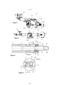
[0028] Figura 1 uma vista em perspectiva esquemática de uma coluna de direção para um veículo automóvel em uma primeira modalidade;[0028] Figure 1 is a schematic perspective view of a steering column for a motor vehicle in a first embodiment;
[0029] Figura 2 uma vista lateral esquemática da coluna de direção da Figura 1.[0029] Figure 2 is a schematic side view of the steering column of Figure 1.
[0030] Figura 3 uma representação esquemática em corte que atravessa as áreas da coluna de direção das Figuras 1 e 2;[0030] Figure 3 a schematic representation in section that crosses the areas of the steering column of Figures 1 and 2;
[0031] Figura 4 uma representação detalhada da vista em corte da coluna de direção da Figura 3;[0031] Figure 4 a detailed representation of the sectional view of the steering column of Figure 3;
[0032] Figura 5 uma vista esquemática em perspectiva da camisa da coluna de direção das Figuras anteriores com uma braçadeira em uma posição de pré-montagem deformada;[0032] Figure 5 is a schematic perspective view of the steering column sleeve of the previous Figures with a clamp in a deformed pre-assembly position;
[0033] Figura 6 uma representação detalhada da braçadeira na camisa da coluna de direção da Figura 5;[0033] Figure 6 a detailed representation of the clamp on the steering column sleeve of Figure 5;
[0034] Figura 7 a camisa da coluna de direção das Figuras 5 e 6 com braçadeira deformada em uma posição montada;[0034] Figure 7 the steering column sleeve of Figures 5 and 6 with deformed clamp in an assembled position;
[0035] Figura 8 uma vista detalhada da braçadeira da Figura 7;[0035] Figure 8 is a detailed view of the clamp of Figure 7;
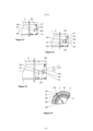
[0036] Figura 9 uma vista lateral esquemática de uma camisa da coluna de direção em uma outra modalidade;[0036] Figure 9 is a schematic side view of a steering column sleeve in another embodiment;
[0037] Figura 10 uma vista lateral esquemática de uma camisa da coluna de direção em uma outra modalidade;[0037] Figure 10 is a schematic side view of a steering column sleeve in another embodiment;
[0038] Figura 11 uma vista lateral esquemática de uma camisa da coluna de direção em uma outra modalidade;[0038] Figure 11 is a schematic side view of a steering column sleeve in another embodiment;
[0039] Figura 12 uma vista lateral esquemática de uma camisa da coluna de direção em ainda uma outra modalidade;[0039] Figure 12 is a schematic side view of a steering column sleeve in yet another embodiment;
[0040] Figura 13 uma vista lateral esquemática de uma camisa da coluna de direção em uma outra modalidade; e[0040] Figure 13 is a schematic side view of a steering column sleeve in another embodiment; and
[0041] Figura 14 uma seção transversal parcial esquemática da camisa da coluna de direção com braçadeira deformada, correspondente à Figura 1.[0041] Figure 14 a schematic partial cross-section of the steering column sleeve with deformed clamp, corresponding to Figure 1.
[0042] A seguir são descritos exemplo de modalidade preferidos com base nas Figuras. Nesse caso, elementos iguais, similares ou de mesma atuação são indicados, nas diferentes Figuras, com números de referência idênticos e é dispensada uma descrição repetida desses elementos a fim de evitar redundâncias.[0042] The following are preferred examples of embodiment based on the Figures. In this case, identical, similar or similar elements are indicated, in the different Figures, with identical reference numbers and a repeated description of these elements is dispensed with in order to avoid redundancies.
[0043] Nas Figuras 1 a 8 é mostrada uma coluna de direção 1 em um primeiro exemplo de modalidade. A coluna de direção 1 apresenta uma camisa da coluna de direção 2 a qual pode ser fixada por uma unidade de montagem 10 e uma unidade de suporte 12 no chassi de um veículo automóvel.[0043] In Figures 1 to 8 a steering column 1 is shown in a first example of modality. The steering column 1 has a
[0044] Na camisa da coluna de direção 2, um eixo de direção 3, que apresenta uma extremidade 30 lateral do volante para a para junção em um volante, está montado de forma giratória em um rolamento 5 ilustrado esquematicamente em torno do eixo giratório 500. O eixo de direção 3 serve para a transmissão de um momento de direção da extremidade lateral ao volante 30 do eixo de direção 3 para componentes da barra de direção situados a jusante, a fim de transmitir, desse modo, por fim, o comando de direção aplicado por um condutor sobre um volante sobre as rodas a serem dirigidas do veículo automóvel.[0044] In the
[0045] O rolamento 5 é executado no exemplo de modalidade como rolamento cilíndrico, nomeadamente, rolamento de esferas. O rolamento 5 apresenta, de forma correspondente, um anel interno do rolamento 52 e anel externo do rolamento 50 contrário ao mesmo, giratório em torno de um eixo giratório 500. Entre o anel externo do rolamento 50 e o anel interno do rolamento 52 são previstos corpos cilíndricos 54 na forma de esferas do rolamento de esferas, que são conduzidas em uma gaiola 56 e que, em conjunto com o anel externo do rolamento 50 e o anel interno do rolamento 52, formam o rolamento 5 como rolamento de esferas.[0045]
[0046] A camisa da coluna de direção 2 pode ser articulada de modo conhecido em torno de um eixo articulado 120 a fim de ajustar a posição da camisa da coluna de direção 2 no sentido vertical Y. A fim de poder produzir a articulação, uma unidade de bloqueio 100 em princípio conhecida do estado da técnica precisa ser movida para sua posição de abertura. Através da articulação da camisa da coluna de direção pode ser obtido um posicionamento do eixo de direção 3 e, em particular, da extremidade lateral ao volante 30 do eixo de direção 3, a fim de mover o volante mantido na extremidade lateral ao volante 30 do eixo de direção 3 para uma posição ideal para o condutor do respectivo veículo automóvel. Além disso, após o destravamento do bloqueio da unidade de bloqueio 100, a camisa da coluna de direção 2 também pode ser movida no sentido horizontal X, a fim de ajustar, do mesmo modo, a extremidade lateral ao volante 30 do eixo de direção 3 às respectivas necessidades ergonômicas do condutor. Mecanismos para o deslocamento vertical, respectivamente, deslocamento horizontal, assim como, para abertura e bloqueio de uma unidade de bloqueio 100 de uma coluna de direção 1 deslocável são bem conhecidos no estado da técnica.[0046] The
[0047] A camisa da coluna de direção 2, assim como, o eixo de direção 3 podem ser telescópicos ao deslocamento horizontal da coluna de direção 1 em relação a uma camisa da coluna de direção 4 posterior, assim como, em relação a uma parte do eixo de direção aqui não mostrada. Além da adequação ao deslocamento horizontal, em caso de acidentes, a capacidade telescópica também serve para permitir um recuo do volante caso o condutor vá de encontro ao mesmo. A capacidade telescópica da coluna de direção é, em princípio, conhecida do estado da técnica.[0047] The
[0048] Na camisa da coluna de direção 2 é previsto um flange 14 para a retenção de unidades de função do volante, por exemplo, para a retenção de uma unidade base de interruptores da coluna de direção ou elementos de acionamento da coluna de direção, como por exemplo, sinais pisca-pisca, interruptor de luz alta ou interruptor do conjunto limpa para-brisas.[0048] A
[0049] A camisa da coluna de direção 2 é formada de forma tubular no exemplo de modalidade mostrado e apresenta, de forma correspondente, uma seção transversal em um plano vertical ao eixo tubular.[0049] The
[0050] Como é possível reconhecer pela representação de corte da Figura 3, o rolamento 5 é disposto entre a camisa da coluna de direção 2 e o eixo de direção 3. Nesse caso, o anel externo do rolamento 50 permanece em contato direto com a superfície interna da camisa da coluna de direção 2. O anel interno do rolamento 52 permanece em contato direto com o lado externo do eixo de direção 3, sendo que o anel interno do rolamento 52 também se encaixa em um rebaixo 32 do eixo de direção.[0050] As it is possible to recognize by the cut representation of Figure 3, the
[0051] O rolamento 5 se encaixa em sentido axial em seu anel externo do rolamento 5 na camisa da coluna de direção 2 em um rebaixo de instalação 20. O rebaixo de instalação 20 é formado, no exemplo de modalidade mostrado, por um recorte por punção e deformação do material recortado livremente por punção da camisa da coluna de direção 2, sendo que o material da camisa da coluna de direção 2 foi deformado de fora para dentro na camisa da coluna de direção. Um rebaixo de instalação 20 para a instalação do anel externo do rolamento 5 em sentido axial também pode ser disponibilizado, contudo, em um outro modo, por exemplo, pela formação de um desvio de diâmetro da camisa da coluna de direção 2, uma parte de soldagem ou de outro modo conhecido.[0051]
[0052] No lado frontal 58 do anel externo do rolamento 50, que é voltado à extremidade lateral ao volante 30 do eixo de direção 3, o rolamento é mantido na camisa da coluna de direção 2 por uma braçadeira 22. A braçadeira 22 é recortada por punção a partir do material da camisa da coluna de direção 2 e o material recortado livremente por punção, desse modo, é deformado de fora para dentro, para a proteção e retenção do rolamento 5 em seu anel externo do rolamento 50, na camisa da coluna de direção 2. A braçadeira 22 consiste, de forma correspondente, no material da camisa da coluna de direção 2 e também é unido ainda em uma só peça à camisa da coluna de direção 2. Em outras palavras, a braçadeira 22 não é totalmente separada por recorte por punção da camisa da coluna de direção 2, mas permanece unida à mesma.[0052] On the
[0053] A braçadeira 22 se estendem primeiramente, de forma essencial, no sentido circunferencial da camisa da coluna de direção 2 formada de modo tubular e, com isso, também em sentido circunferencial do rolamento 5 e a partir dessa posição, é deformada de fora para dentro na camisa da coluna de direção 2, a fim de manter o rolamento 5 comprimido em sua posição no rebaixo de instalação 20.[0053] The
[0054] Na Figura 14 é mostrada uma seção transversal parcial esquemática da camisa da coluna de direção 2 na área da seção de retenção. Na camisa da coluna de direção 2, o eixo de direção 3 é colocado de forma giratória no rolamento 5 em torno do eixo giratório 500. O rolamento 5 compreende o anel externo do rolamento 50 que é montado na camisa da coluna de direção 2. A camisa da coluna de direção 2 apresenta a braçadeira 22, sendo que essa braçadeira 22 é unida à seção de retenção da camisa da coluna de direção 2 ao longo da aresta flexível 222 e apresenta a extremidade livre 226. Essa extremidade livre 226 da braçadeira 22 é curvada no sentido ao eixo giratório 500 em torno da aresta flexível 222 e assegura o anel externo do rolamento 50 e, com isso, o rolamento 5, contra um deslocamento possível no sentido do eixo giratório 500.[0054] Figure 14 shows a schematic partial cross-section of the
[0055] O eixo giratório 500 é projetado ao longo do sentido de projeção 228 na aresta flexível 222, pelo que é formado o eixo giratório projetado 501 e esse se encontra com a aresta flexível 222. O sentido de projeção 228 é direcionado partindo do eixo giratório 500 radialmente para fora, para a aresta flexível 222, sendo que a projeção do eixo giratório 500 ocorre radialmente para fora ao longo desse sentido de projeção até que o eixo giratório projetado 501 encontre a aresta flexível 222 pelo menos em um ponto.[0055] The
[0056] Nas Figuras 9 e 14 é mostrado o eixo giratório projetado 501, que é projetado na aresta flexível 222 partindo do eixo giratório 500 ao longo do sentido de projeção 228. Nesse caso, o eixo giratório projetado 501 se sobrepõe diretamente à aresta flexível 222 de modo que a aresta flexível 222 e o eixo giratório projetado 501 se encontrem infinitamente em muitos pontos e, com isso, sejam paralelos, sendo que o ângulo de projeção β, em função do paralelismo, apresente um valor de 0°.[0056] In Figures 9 and 14, the projected
[0057] Nas Figuras 5 a 8 são mostrados esquematicamente dois estados da camisa da coluna de direção 2, nomeadamente, um estado pré-montado nas Figuras 5 e 6, no qual a braçadeira 22 ainda não é curvada para a retenção do rolamento 5 e, nas Figuras 7 e 8, um estado da camisa da coluna de direção 2, no qual a braçadeira 22 já está completamente curvada a fim de pressionar o rolamento 5 com uma tensão prévia definida no rebaixo de instalação 20 e, com isso, mantê-lo firme na camisa da coluna de direção 2.[0057] In Figures 5 to 8, two states of the
[0058] Nas Figuras 5 e 6 é possível reconhecer a braçadeira 22 em detalhes em um estado pré-montado não deformado. Visto que a braçadeira 22 é construída a partir do material da camisa da coluna de direção 2, a mesma é formada como parte da camisa da coluna de direção 2 e é unida ao longo de uma aresta flexível 222 à camisa da coluna de direção 2 restante. A aresta flexível 222 se estende essencialmente paralela ao eixo giratório 500. A braçadeira 22, por sua vez, se estende essencialmente no sentido circunferencial da camisa da coluna de direção tubular 2 e, com isso, também no sentido circunferencial do anel externo do rolamento 50 do rolamento 5 montado na camisa da coluna de direção 2.[0058] In Figures 5 and 6 it is possible to recognize the
[0059] Como se segue a partir das Figuras, a braçadeira 22 apresenta uma chanfradura em seu lado 220 voltado ao rolamento 5, para, mediante a deformação da braçadeira 22, pela aplicação de um efeito de cunha que atua pela chanfradura, aplicar uma força de compressão definida sobre o anel externo 50 do rolamento 5. Através do fato que a chanfradura está prevista no lado 220 da braçadeira 22 voltado ao rolamento 5, podem ser absorvidas tolerâncias que ocorrem na largura B do anel externo 50 do rolamento 5, de modo que não precisem ser colocadas quaisquer especificações elevadas na adequação à tolerância da largura B do rolamento 5. De forma correspondente, o rolamento 5 pode ser selecionado de forma econômica.[0059] As follows from the Figures, the
[0060] Além disso, dessa maneira, também são reduzidas as especificações de precisão de posicionamento dos recortes por punção para a formação do rebaixo de instalação 20 e da braçadeira 22, visto que também aqui tolerâncias possíveis podem ser compensadas pela chanfradura do lado 220 da braçadeira 22 voltado ao rolamento 5. No geral, é possível simplificar a produção e montagem da coluna de direção 1 desse modo.[0060] In addition, in this way, the positioning accuracy specifications of the punch cutouts for the formation of the
[0061] Como também pode ser reconhecido de forma esquemática a partir da Figura 9, o lado 220 da braçadeira 22 voltado rolamento 5 é formado em estado não-deformado sob um ângulo de inclinação α em relação ao eixo giratório projetado 501, sendo que esse eixo giratório projetado 501 que parte do eixo giratório 500 é projetado radialmente para fora sobre a aresta flexível 222. O ângulo de inclinação α está tipicamente na faixa de 45° a 85° e, de forma preferida, na faixa de 60° a 75°. Pelas faixas de ângulos especificadas, um efeito de cunha pode ser aplicado para compensação de tolerâncias, sendo que, ao mesmo tempo, ao longo do eixo giratório 500, forças aplicadas no rolamento 5 são introduzidas essencialmente em um sentido na braçadeira 22, que está essencialmente paralela à aresta flexível 222 formada após a flexão. Com isso, forças axiais aplicadas sobre o rolamento 5 não provocam qualquer deformação adicional da braçadeira 22 em torno da aresta flexível 222, de modo que uma elevada rigidez axial seja obtida.[0061] As can also be recognized schematically from Figure 9, the
[0062] No exemplo de modalidade mostrado é previsto ainda um lado livre 224 para a definição da braçadeira 22 recortada por punção. O lado chanfrado 220 voltado ao rolamento 5 e o lado livre 224 se encontram de modo que a braçadeira 22 forma um triângulo esquemático. A braçadeira 22 pode apresentar, contudo, quaisquer outras formas e formar, por exemplo, também uma forma de base retangular ou quadrada entre a aresta flexível 222 e o lado restante da braçadeira 22. Contudo, o lado voltado 220 ao rolamento 5 é chanfrado, de forma preferida, como descrito acima, a fim de disponibilizar a compensação de tolerâncias descrita. A forma de base da braçadeira 22 é, portanto, de forma preferida, triangular ou poligonal com pelo menos um lado chanfrado 220 voltado ao rolamento 5.[0062] In the example of embodiment shown, a
[0063] Nas Figuras 7 e 8 é mostrada a coluna de direção 1 em um estado no qual a braçadeira 22 é deformada de tal modo que a mesma é curvada de fora para dentro em torno de sua aresta flexível 222, para dentro da camisa da coluna de direção 2. O alinhamento geral da braçadeira 22 permanece, nesse caso, em sentido circunferencial da camisa da coluna de direção 2, respectivamente, do rolamento 5. A aresta flexível 222, em torno da qual a braçadeira 22 foi deformada, se estende essencialmente paralela ao eixo giratório 500.[0063] In Figures 7 and 8, the steering column 1 is shown in a state in which the
[0064] Uma força de compressão, respectivamente, uma tensão prévia especificada do rolamento 5 no rebaixo de instalação 20, na deformação da braçadeira 22, em função do lado chanfrado 220 da braçadeira 22 voltado ao rolamento 5, pode ser obtida por uma deformação braçadeira 22 controlada por força. Pela aplicação de uma força controlada correspondente para a deformação da braçadeira 22, uma força de compressão ou tensão prévia especificada pode ser obtida independente das respectivas tolerâncias existentes.[0064] A compressive force, respectively, a specified pretension of the
[0065] É possível reconhecer, particularmente, na Figura 8 que o voltado lado 220 da braçadeira 22 voltado ao rolamento 5 se encaixa no anel externo do rolamento 50 e, em particular, no lado frontal 58 do anel externo do rolamento 50. Visto que o lado 220 da braçadeira 22 voltado ao rolamento é chanfrado, a braçadeira 22, dentro de uma faixa de tolerância predeterminada, sempre entra em contato com o lado frontal 58 do anel externo do rolamento 50 do rolamento 5 e exerce, em uma deformação da braçadeira 22 controlada por força, uma força de tensão prévia em sentido axial, ou seja, no sentido do eixo giratório 500, sobre o rolamento 5.[0065] It is possible to recognize particularly in Figure 8 that the facing
[0066] Em uma variação não mostrada, a braçadeira 22 também pode engatar em uma ranhura circular do rolamento 5.[0066] In a variation not shown, clamp 22 may also engage a circular groove of
[0067] Além disso, em uma outra variação não mostrada, o rebaixo de instalação 20, que sustenta o rolamento em sentido axial, pode ser realizado, do mesmo modo, por uma braçadeira de acordo com a invenção.[0067] Furthermore, in another variation not shown, the
[0068] A partir da Figura 9 é possível reconhecer particularmente bem a função da possível compensação de tolerância por meio da braçadeira chanfrada 22. São especificadas aqui uma largura máxima Bmax e uma largura mínima Bmin para a largura do anel externo do rolamento 50 - respectivamente partindo do rebaixo de instalação 20. Através do lado chanfrado 220 voltado ao rolamento 5 é possível compensar de forma correspondente à faixa de tolerância do rolamento 5 formada entre Bmax e Bmin.[0068] From Figure 9 it is possible to recognize particularly well the function of the possible tolerance compensation by means of the chamfered
[0069] Pelo fato de que a braçadeira 22 se estende no sentido circunferencial da camisa da coluna de direção 2 e a aresta flexível 222 da braçadeira 22 se estende essencialmente paralela ao eixo giratório 500, são incorporadas forças no sentido do eixo giratório 500, essencialmente no plano da braçadeira 22. As forças axiais atuam de forma correspondente, na braçadeira 22, essencialmente paralelas à aresta flexível 222, de modo que não sejam incorporados quaisquer momentos de flexão adicionais para deformação contínua da braçadeira 22. Pelo contrário, as forças axiais são incorporadas no plano da braçadeira de modo que não ocorra qualquer deformação da braçadeira 22 e, de forma correspondente, seja obtida uma elevada rigidez da junção do rolamento 5 na camisa da coluna de direção 2.[0069] Because the
[0070] Para comparação e ilustração, em uma braçadeira, cuja aresta flexível se estende essencialmente vertical ao eixo giratório, foram incorporados momentos de flexão adicionais às forças axiais de qualquer tipo na braçadeira, as quais podem levar, de forma correspondente, a uma deformação contínua da braçadeira e, com isso, a uma redução das respectivas forças de retenção.[0070] For comparison and illustration, in a clamp, whose flexible edge extends essentially vertical to the rotating axis, additional bending moments have been incorporated to the axial forces of any type in the clamp, which can correspondingly lead to a deformation continuous movement of the clamp and, as a result, to a reduction in the respective holding forces.
[0071] De forma correspondente, pela braçadeira 22 descrita acima pode ser obtida uma junção do rolamento 5 na camisa da coluna de direção 2, a qual apresenta uma elevada rigidez axial e permite, ao mesmo tempo, um assento do rolamento livre de folga 5 em especificações de tolerância reduzidas no rolamento 5, assim como, no posicionamento do rebaixo de instalação 20 e da braçadeira 22 na camisa da coluna de direção 2. Além disso, são evitadas partes adicionais para a junção do rolamento 5 na camisa da coluna de direção 2 pela formação da braçadeira 22 a partir do material da camisa da coluna de direção 2.[0071] Correspondingly, by means of the
[0072] Na Figura 10 é mostrada uma outra representação esquemática de uma parte de uma coluna de direção em uma vista lateral na camisa da coluna de direção 2. A braçadeira 22 apresenta novamente um lado 220 voltado ao rolamento 5, o qual é chanfrado. O lado livre 224 é chanfrado no exemplo de modalidade, do mesmo modo, contra o sentido circunferencial, de modo que a braçadeira 22 forma essencialmente um triângulo equilátero com a base na aresta flexível 222. Também outras formas de triângulos da braçadeira 22 são possíveis contanto que o alinhamento geral da braçadeira não-deformada 22 se encontre no sentido circunferencial da camisa da coluna de direção 2, respectivamente, no sentido circunferencial do rolamento 5 e uma aresta flexível 222 seja formada essencialmente paralela ao eixo giratório 500.[0072] In Figure 10 is shown another schematic representation of a part of a steering column in a side view on the
[0073] Na Figura 11 é mostrada uma outra possibilidade da formação da braçadeira 22, sendo que a braçadeira 22 apresenta aqui, novamente, uma aresta flexível 222 que se estende paralela ao eixo giratório 500 e o lado chanfrado 220 voltado ao rolamento. O lado livre 224 coincide aqui com o lado frontal 24 da camisa da coluna de direção 2.[0073] In Figure 11, another possibility of forming the
[0074] Na Figura 12 é mostrado um outro formato da braçadeira 22, sendo que sendo que aqui são previstas duas braçadeiras opostas 22, as quais ambas se estendem essencialmente no sentido circunferencial da camisa da coluna de direção 2 e que estão presentes em uma reentrância por punção conjunta. Os dois eixos giratórios projetados 501 são projetados partindo do eixo giratório 500 radialmente para fora sobre a respectiva aresta flexível 222 da braçadeira 22 correspondente. Nesse caso, o respectivo eixo giratório 501 se encontra com sua aresta flexível 222 atribuída pela projeção. A respectiva aresta flexível 222 e o eixo giratório projetado 501 atribuído à mesma se encontram na variação de modalidade representada aqui infinitamente em vários pontos e são, com isso, paralelos, sendo que o ângulo de projeção β, em função do paralelismo, apresenta um valor de 0°.[0074] In Figure 12, another format of the
[0075] As duas braçadeiras 22 podem, assim, ser curvadas, que seus respectivos lados 220 voltados ao rolamento 5, que são novamente chanfrados, disponibilizam tanto uma compensação de tolerâncias como uma força de tensão prévia definida, quando as mesmas são curvadas controladas por força.[0075] The two clamps 22 can thus be curved, that their
[0076] Na Figura 13 é mostrada uma representação esquemática de uma parte de uma coluna de direção em uma vista lateral na camisa da coluna de direção 2. A camisa da coluna de direção 2 apresenta a braçadeira 22, sendo que essa braçadeira 22 é unida à seção de retenção da camisa da coluna de direção 2 ao longo da aresta flexível 222 e apresenta a extremidade livre 226. Além disso, a braçadeira 22 compreende um lado 220 voltado ao rolamento 5 e o lado livre 224. O eixo giratório projetado 501 é projetado partindo do eixo giratório 500 radialmente para fora, sobre a aresta flexível 222. Nesse caso, o eixo giratório 501 se encontra com a aresta flexível 222 exatamente em um ponto, visto que a linha de flexão 222 é disposta em um ângulo de projeção β com um valor maior do 0° ao eixo giratório projetado 501. No exemplo, o ângulo de projeção β entre a aresta flexível 222 e o eixo giratório projetado 501 é de 15°.[0076] In Figure 13 is shown a schematic representation of a part of a steering column in a side view on the
[0077] Contanto que aplicáveis, todas as características individuais, que são representadas nos exemplos de modalidade individuais, podem ser combinadas e/ou trocadas entre si, sem deixar o escopo da invenção. NÚMEROS DE REFERÊNCIA 1 coluna de direção 10 unidade de montagem 12 unidade de suporte 14 flange 100 unidade de bloqueio 120 eixo articulado 2 camisa da coluna de direção 20 rebaixo de instalação 22 braçadeira 24 lado frontal 220 lado voltado ao rolamento 222 aresta flexível 224 lado livre 226 extremidade livre 228 sentido de projeção 3 eixo de direção 30 extremidade lateral ao volante 32 rebaixo 4 camisa da coluna de direção posterior 5 rolamento 50 anel externo do rolamento 52 anel interno do rolamento 54 corpos cilíndricos 56 gaiola 58 lado frontal do anel externo do rolamento 500 eixo giratório 501 eixo giratório projetado X sentido horizontal y sentido vertical B largura do rolamento Bmin largura mínima do rolamento Bmax largura máxima do rolamento α ângulo de inclinação da chanfradura β ângulo de projeção[0077] As long as applicable, all individual characteristics, which are represented in the individual embodiment examples, can be combined and/or exchanged with each other, without leaving the scope of the invention. REFERENCE NUMBERS 1
Claims (8)
Applications Claiming Priority (3)
| Application Number | Priority Date | Filing Date | Title |
|---|---|---|---|
| DE102014107292.8 | 2014-05-23 | ||
| DE102014107292.8A DE102014107292B3 (en) | 2014-05-23 | 2014-05-23 | Steering column for a motor vehicle |
| PCT/EP2015/058953 WO2015176914A1 (en) | 2014-05-23 | 2015-04-24 | Steering column for a motor vehicle |
Publications (2)
| Publication Number | Publication Date |
|---|---|
| BR112016025708A2 BR112016025708A2 (en) | 2017-08-15 |
| BR112016025708B1 true BR112016025708B1 (en) | 2022-01-18 |
Family
ID=53184578
Family Applications (1)
| Application Number | Title | Priority Date | Filing Date |
|---|---|---|---|
| BR112016025708-1A BR112016025708B1 (en) | 2014-05-23 | 2015-04-24 | STEERING COLUMN FOR A MOTOR VEHICLE, AND METHOD FOR ASSEMBLY OF A STEERING COLUMN FOR A MOTOR VEHICLE |
Country Status (8)
| Country | Link |
|---|---|
| US (1) | US10040472B2 (en) |
| EP (1) | EP3146223B1 (en) |
| CN (1) | CN106604856B (en) |
| BR (1) | BR112016025708B1 (en) |
| DE (1) | DE102014107292B3 (en) |
| ES (1) | ES2744307T3 (en) |
| PL (1) | PL3146223T3 (en) |
| WO (1) | WO2015176914A1 (en) |
Families Citing this family (7)
| Publication number | Priority date | Publication date | Assignee | Title |
|---|---|---|---|---|
| DE102014107292B3 (en) * | 2014-05-23 | 2015-05-21 | Thyssenkrupp Presta Ag | Steering column for a motor vehicle |
| DE102015000027A1 (en) * | 2015-01-08 | 2016-07-14 | Thyssenkrupp Ag | Steering column with flexibly mountable bearing seat |
| US10532761B2 (en) * | 2017-12-06 | 2020-01-14 | Thyssenkrupp Presta Ag | Spindle and steering column assembly having same |
| GB2575993B (en) * | 2018-07-31 | 2022-07-13 | Zf Automotive Uk Ltd | Steering column assemblies |
| JP2022541324A (en) | 2019-07-25 | 2022-09-22 | ヒタチ・エナジー・スウィツァーランド・アクチェンゲゼルシャフト | Configuration consisting of power semiconductor modules and coolers |
| KR20220068781A (en) * | 2020-11-19 | 2022-05-26 | 주식회사 만도 | Steering column and steering apparatus having the same |
| CN112893656A (en) * | 2021-01-20 | 2021-06-04 | 湖北三环汽车方向机有限公司 | Positioning structure and positioning process for thin-wall pipe part assembling bearing |
Family Cites Families (20)
| Publication number | Priority date | Publication date | Assignee | Title |
|---|---|---|---|---|
| DE2905130C2 (en) * | 1979-02-10 | 1983-01-27 | Fa. Leopold Kostal, 5880 Lüdenscheid | Jacketed pipe on the steering column of motor vehicles |
| FR2756885B1 (en) * | 1996-12-09 | 1999-01-15 | Skf France | STEERING COLUMN BEARING FOR MOTOR VEHICLES |
| JPH11342853A (en) * | 1998-06-03 | 1999-12-14 | Toyota Motor Corp | Method of fixing bearing to column tube |
| FR2781747B1 (en) * | 1998-07-31 | 2000-09-22 | Lemforder Nacam Sa | ASSEMBLY OF A CONTROL ASSEMBLY WITH A MOTOR VEHICLE STEERING COLUMN |
| DE19860345A1 (en) * | 1998-12-24 | 2000-07-06 | Fag Automobiltechnik Ag | Mounting ring for bearing has a press fit sleeve with grip tags to secure the outer bearing ring against rotation |
| JP4120977B2 (en) * | 1999-06-04 | 2008-07-16 | 株式会社ジェイテクト | Bearing device for steering column |
| ES2314778T3 (en) * | 2000-04-06 | 2009-03-16 | Thyssenkrupp Presta Aktiengesellschaft | BOX SUPPORT FOR THE SUPPORT OF A STEERING TREE. |
| FR2824367B1 (en) * | 2001-05-04 | 2003-07-18 | Roulements Soc Nouvelle | ASSEMBLY COMPRISING AN INSTRUMENT BEARING AND A HOUSING ASSOCIATED BY A SLEEVE PIECE |
| FR2824368B1 (en) * | 2001-05-04 | 2003-09-05 | Roulements Soc Nouvelle | ASSEMBLY COMPRISING AN INSTRUMENT BEARING AND A HOUSING ASSOCIATED BY A MONOBLOCK SENSOR |
| JP4657590B2 (en) | 2002-08-28 | 2011-03-23 | オイレス工業株式会社 | Sliding bearing and bearing mechanism including the same |
| DE10244245A1 (en) * | 2002-09-24 | 2004-03-25 | Leopold Kostal Gmbh & Co. Kg | Device for attaching switch module to steering-column sleeve of motor vehicle, transmits clamping force to securing member via stator side of bearing to provide biasing force |
| CN200977941Y (en) * | 2006-12-01 | 2007-11-21 | 武汉捷隆汽车电动转向系统有限公司 | Steering pipe column structure for automobile |
| DE102007013039A1 (en) | 2007-03-19 | 2008-09-25 | Schaeffler Kg | Method of arranging an undivided rolling bearing on a shaft and rolling bearing therefor |
| JP5034629B2 (en) * | 2007-04-11 | 2012-09-26 | 日本精工株式会社 | Steering device |
| FR2921327B1 (en) | 2007-09-21 | 2010-02-19 | Autoliv Dev | DEVICE FOR FASTENING A FLYWHEEL HAS FIXED ON A STEERING COLUMN AND STEERING WHEEL |
| CN202046353U (en) | 2011-01-10 | 2011-11-23 | 蒂森克虏伯富奥汽车转向柱(长春)有限公司 | Ball bearing support device and steering post with same |
| JP5958202B2 (en) | 2012-09-07 | 2016-07-27 | 日本精工株式会社 | Manufacturing method of steering device |
| US9347492B2 (en) * | 2013-08-23 | 2016-05-24 | Steering Solutions Ip Holding Corporation | Retainer cap for shaft assembly |
| DE102014107292B3 (en) * | 2014-05-23 | 2015-05-21 | Thyssenkrupp Presta Ag | Steering column for a motor vehicle |
| DE102014008933A1 (en) * | 2014-06-17 | 2015-12-17 | Leopold Kostal Gmbh & Co. Kg | Device for fastening a jacket tube switch module to the jacket tube of a steering shaft of a motor vehicle |
-
2014
- 2014-05-23 DE DE102014107292.8A patent/DE102014107292B3/en active Active
-
2015
- 2015-04-24 WO PCT/EP2015/058953 patent/WO2015176914A1/en active Application Filing
- 2015-04-24 US US15/311,652 patent/US10040472B2/en active Active
- 2015-04-24 BR BR112016025708-1A patent/BR112016025708B1/en active IP Right Grant
- 2015-04-24 PL PL15729345T patent/PL3146223T3/en unknown
- 2015-04-24 CN CN201580025983.7A patent/CN106604856B/en active Active
- 2015-04-24 EP EP15729345.7A patent/EP3146223B1/en active Active
- 2015-04-24 ES ES15729345T patent/ES2744307T3/en active Active
Also Published As
| Publication number | Publication date |
|---|---|
| EP3146223B1 (en) | 2019-06-05 |
| ES2744307T3 (en) | 2020-02-24 |
| CN106604856A (en) | 2017-04-26 |
| US20170096159A1 (en) | 2017-04-06 |
| BR112016025708A2 (en) | 2017-08-15 |
| EP3146223A1 (en) | 2017-03-29 |
| PL3146223T3 (en) | 2019-11-29 |
| CN106604856B (en) | 2019-10-18 |
| US10040472B2 (en) | 2018-08-07 |
| WO2015176914A1 (en) | 2015-11-26 |
| DE102014107292B3 (en) | 2015-05-21 |
Similar Documents
| Publication | Publication Date | Title |
|---|---|---|
| BR112016025708B1 (en) | STEERING COLUMN FOR A MOTOR VEHICLE, AND METHOD FOR ASSEMBLY OF A STEERING COLUMN FOR A MOTOR VEHICLE | |
| US9499190B2 (en) | Adjustable steering column assembly having self-de-lashing power-rake mechanism | |
| JP6493211B2 (en) | Position adjustable steering system | |
| US9283982B2 (en) | Steering column | |
| US20150101444A1 (en) | Position adjustable steering device | |
| JP5595807B2 (en) | Steering column device | |
| JP2009096409A (en) | Electric tilt steering device | |
| EP2602170A1 (en) | Steering apparatus | |
| EP2899096B1 (en) | Tilt-type steering device | |
| JP7310828B2 (en) | steering column device | |
| JP5737456B2 (en) | Steering column and telescopic steering device | |
| CN107848559B (en) | Position adjusting device for steering wheel | |
| JP4683456B2 (en) | Steering device | |
| JP7424306B2 (en) | steering column device | |
| JP2014076805A5 (en) | ||
| US20150203146A1 (en) | Tilt steering column device | |
| JP6402922B2 (en) | Steering device | |
| KR20090091850A (en) | The tie rod of automatic adjusting length type and the steering apparatus for vehicle having the same | |
| JP6403334B2 (en) | Steering device | |
| JP5233246B2 (en) | Electric telescopic adjustment type steering device | |
| JP6379863B2 (en) | Steering wheel position adjusting device and manufacturing method thereof | |
| US9845105B2 (en) | Adjustment mounting bracket assembly for steering column | |
| JP6613820B2 (en) | Steering device | |
| KR100723722B1 (en) | Adjusting Lever for Tilting and Telescopic Device and Steering Column Including Same | |
| JP7314951B2 (en) | steering column and steering gear |
Legal Events
| Date | Code | Title | Description |
|---|---|---|---|
| B06U | Preliminary requirement: requests with searches performed by other patent offices: procedure suspended [chapter 6.21 patent gazette] | ||
| B350 | Update of information on the portal [chapter 15.35 patent gazette] | ||
| B09A | Decision: intention to grant [chapter 9.1 patent gazette] | ||
| B16A | Patent or certificate of addition of invention granted [chapter 16.1 patent gazette] |
Free format text: PRAZO DE VALIDADE: 20 (VINTE) ANOS CONTADOS A PARTIR DE 24/04/2015, OBSERVADAS AS CONDICOES LEGAIS. |