BR112016021614B1 - THREE-DIMENSIONAL PRINT METHOD (3D), METHOD TO IDENTIFY HOW TO APPLY A MODIFICATION AGENT DURING A THREE-DIMENSIONAL PRINT METHOD (3D) AND COMPUTATIONAL MODELING METHOD TO IDENTIFY HOW TO APPLY A MODIFICATION AGENT DURING A THREE-DIMENSIONAL PRINT METHOD (3D) - Google Patents
THREE-DIMENSIONAL PRINT METHOD (3D), METHOD TO IDENTIFY HOW TO APPLY A MODIFICATION AGENT DURING A THREE-DIMENSIONAL PRINT METHOD (3D) AND COMPUTATIONAL MODELING METHOD TO IDENTIFY HOW TO APPLY A MODIFICATION AGENT DURING A THREE-DIMENSIONAL PRINT METHOD (3D) Download PDFInfo
- Publication number
- BR112016021614B1 BR112016021614B1 BR112016021614-8A BR112016021614A BR112016021614B1 BR 112016021614 B1 BR112016021614 B1 BR 112016021614B1 BR 112016021614 A BR112016021614 A BR 112016021614A BR 112016021614 B1 BR112016021614 B1 BR 112016021614B1
- Authority
- BR
- Brazil
- Prior art keywords
- sinterable material
- modifying agent
- layer
- amount
- temperature
- Prior art date
Links
Images


Classifications
-
- B—PERFORMING OPERATIONS; TRANSPORTING
- B29—WORKING OF PLASTICS; WORKING OF SUBSTANCES IN A PLASTIC STATE IN GENERAL
- B29C—SHAPING OR JOINING OF PLASTICS; SHAPING OF MATERIAL IN A PLASTIC STATE, NOT OTHERWISE PROVIDED FOR; AFTER-TREATMENT OF THE SHAPED PRODUCTS, e.g. REPAIRING
- B29C64/00—Additive manufacturing, i.e. manufacturing of three-dimensional [3D] objects by additive deposition, additive agglomeration or additive layering, e.g. by 3D printing, stereolithography or selective laser sintering
- B29C64/30—Auxiliary operations or equipment
- B29C64/386—Data acquisition or data processing for additive manufacturing
-
- B—PERFORMING OPERATIONS; TRANSPORTING
- B29—WORKING OF PLASTICS; WORKING OF SUBSTANCES IN A PLASTIC STATE IN GENERAL
- B29C—SHAPING OR JOINING OF PLASTICS; SHAPING OF MATERIAL IN A PLASTIC STATE, NOT OTHERWISE PROVIDED FOR; AFTER-TREATMENT OF THE SHAPED PRODUCTS, e.g. REPAIRING
- B29C64/00—Additive manufacturing, i.e. manufacturing of three-dimensional [3D] objects by additive deposition, additive agglomeration or additive layering, e.g. by 3D printing, stereolithography or selective laser sintering
- B29C64/10—Processes of additive manufacturing
- B29C64/165—Processes of additive manufacturing using a combination of solid and fluid materials, e.g. a powder selectively bound by a liquid binder, catalyst, inhibitor or energy absorber
-
- B—PERFORMING OPERATIONS; TRANSPORTING
- B29—WORKING OF PLASTICS; WORKING OF SUBSTANCES IN A PLASTIC STATE IN GENERAL
- B29C—SHAPING OR JOINING OF PLASTICS; SHAPING OF MATERIAL IN A PLASTIC STATE, NOT OTHERWISE PROVIDED FOR; AFTER-TREATMENT OF THE SHAPED PRODUCTS, e.g. REPAIRING
- B29C64/00—Additive manufacturing, i.e. manufacturing of three-dimensional [3D] objects by additive deposition, additive agglomeration or additive layering, e.g. by 3D printing, stereolithography or selective laser sintering
- B29C64/10—Processes of additive manufacturing
- B29C64/171—Processes of additive manufacturing specially adapted for manufacturing multiple 3D objects
- B29C64/182—Processes of additive manufacturing specially adapted for manufacturing multiple 3D objects in parallel batches
-
- B—PERFORMING OPERATIONS; TRANSPORTING
- B29—WORKING OF PLASTICS; WORKING OF SUBSTANCES IN A PLASTIC STATE IN GENERAL
- B29C—SHAPING OR JOINING OF PLASTICS; SHAPING OF MATERIAL IN A PLASTIC STATE, NOT OTHERWISE PROVIDED FOR; AFTER-TREATMENT OF THE SHAPED PRODUCTS, e.g. REPAIRING
- B29C64/00—Additive manufacturing, i.e. manufacturing of three-dimensional [3D] objects by additive deposition, additive agglomeration or additive layering, e.g. by 3D printing, stereolithography or selective laser sintering
- B29C64/20—Apparatus for additive manufacturing; Details thereof or accessories therefor
- B29C64/205—Means for applying layers
- B29C64/209—Heads; Nozzles
-
- B—PERFORMING OPERATIONS; TRANSPORTING
- B29—WORKING OF PLASTICS; WORKING OF SUBSTANCES IN A PLASTIC STATE IN GENERAL
- B29C—SHAPING OR JOINING OF PLASTICS; SHAPING OF MATERIAL IN A PLASTIC STATE, NOT OTHERWISE PROVIDED FOR; AFTER-TREATMENT OF THE SHAPED PRODUCTS, e.g. REPAIRING
- B29C64/00—Additive manufacturing, i.e. manufacturing of three-dimensional [3D] objects by additive deposition, additive agglomeration or additive layering, e.g. by 3D printing, stereolithography or selective laser sintering
- B29C64/20—Apparatus for additive manufacturing; Details thereof or accessories therefor
- B29C64/205—Means for applying layers
- B29C64/214—Doctor blades
-
- B—PERFORMING OPERATIONS; TRANSPORTING
- B29—WORKING OF PLASTICS; WORKING OF SUBSTANCES IN A PLASTIC STATE IN GENERAL
- B29C—SHAPING OR JOINING OF PLASTICS; SHAPING OF MATERIAL IN A PLASTIC STATE, NOT OTHERWISE PROVIDED FOR; AFTER-TREATMENT OF THE SHAPED PRODUCTS, e.g. REPAIRING
- B29C64/00—Additive manufacturing, i.e. manufacturing of three-dimensional [3D] objects by additive deposition, additive agglomeration or additive layering, e.g. by 3D printing, stereolithography or selective laser sintering
- B29C64/20—Apparatus for additive manufacturing; Details thereof or accessories therefor
- B29C64/227—Driving means
-
- B—PERFORMING OPERATIONS; TRANSPORTING
- B29—WORKING OF PLASTICS; WORKING OF SUBSTANCES IN A PLASTIC STATE IN GENERAL
- B29C—SHAPING OR JOINING OF PLASTICS; SHAPING OF MATERIAL IN A PLASTIC STATE, NOT OTHERWISE PROVIDED FOR; AFTER-TREATMENT OF THE SHAPED PRODUCTS, e.g. REPAIRING
- B29C64/00—Additive manufacturing, i.e. manufacturing of three-dimensional [3D] objects by additive deposition, additive agglomeration or additive layering, e.g. by 3D printing, stereolithography or selective laser sintering
- B29C64/20—Apparatus for additive manufacturing; Details thereof or accessories therefor
- B29C64/264—Arrangements for irradiation
-
- B—PERFORMING OPERATIONS; TRANSPORTING
- B29—WORKING OF PLASTICS; WORKING OF SUBSTANCES IN A PLASTIC STATE IN GENERAL
- B29C—SHAPING OR JOINING OF PLASTICS; SHAPING OF MATERIAL IN A PLASTIC STATE, NOT OTHERWISE PROVIDED FOR; AFTER-TREATMENT OF THE SHAPED PRODUCTS, e.g. REPAIRING
- B29C64/00—Additive manufacturing, i.e. manufacturing of three-dimensional [3D] objects by additive deposition, additive agglomeration or additive layering, e.g. by 3D printing, stereolithography or selective laser sintering
- B29C64/30—Auxiliary operations or equipment
- B29C64/386—Data acquisition or data processing for additive manufacturing
- B29C64/393—Data acquisition or data processing for additive manufacturing for controlling or regulating additive manufacturing processes
-
- B—PERFORMING OPERATIONS; TRANSPORTING
- B29—WORKING OF PLASTICS; WORKING OF SUBSTANCES IN A PLASTIC STATE IN GENERAL
- B29C—SHAPING OR JOINING OF PLASTICS; SHAPING OF MATERIAL IN A PLASTIC STATE, NOT OTHERWISE PROVIDED FOR; AFTER-TREATMENT OF THE SHAPED PRODUCTS, e.g. REPAIRING
- B29C64/00—Additive manufacturing, i.e. manufacturing of three-dimensional [3D] objects by additive deposition, additive agglomeration or additive layering, e.g. by 3D printing, stereolithography or selective laser sintering
- B29C64/40—Structures for supporting 3D objects during manufacture and intended to be sacrificed after completion thereof
-
- B—PERFORMING OPERATIONS; TRANSPORTING
- B29—WORKING OF PLASTICS; WORKING OF SUBSTANCES IN A PLASTIC STATE IN GENERAL
- B29C—SHAPING OR JOINING OF PLASTICS; SHAPING OF MATERIAL IN A PLASTIC STATE, NOT OTHERWISE PROVIDED FOR; AFTER-TREATMENT OF THE SHAPED PRODUCTS, e.g. REPAIRING
- B29C67/00—Shaping techniques not covered by groups B29C39/00 - B29C65/00, B29C70/00 or B29C73/00
-
- B—PERFORMING OPERATIONS; TRANSPORTING
- B33—ADDITIVE MANUFACTURING TECHNOLOGY
- B33Y—ADDITIVE MANUFACTURING, i.e. MANUFACTURING OF THREE-DIMENSIONAL [3-D] OBJECTS BY ADDITIVE DEPOSITION, ADDITIVE AGGLOMERATION OR ADDITIVE LAYERING, e.g. BY 3-D PRINTING, STEREOLITHOGRAPHY OR SELECTIVE LASER SINTERING
- B33Y10/00—Processes of additive manufacturing
-
- B—PERFORMING OPERATIONS; TRANSPORTING
- B33—ADDITIVE MANUFACTURING TECHNOLOGY
- B33Y—ADDITIVE MANUFACTURING, i.e. MANUFACTURING OF THREE-DIMENSIONAL [3-D] OBJECTS BY ADDITIVE DEPOSITION, ADDITIVE AGGLOMERATION OR ADDITIVE LAYERING, e.g. BY 3-D PRINTING, STEREOLITHOGRAPHY OR SELECTIVE LASER SINTERING
- B33Y30/00—Apparatus for additive manufacturing; Details thereof or accessories therefor
-
- B—PERFORMING OPERATIONS; TRANSPORTING
- B33—ADDITIVE MANUFACTURING TECHNOLOGY
- B33Y—ADDITIVE MANUFACTURING, i.e. MANUFACTURING OF THREE-DIMENSIONAL [3-D] OBJECTS BY ADDITIVE DEPOSITION, ADDITIVE AGGLOMERATION OR ADDITIVE LAYERING, e.g. BY 3-D PRINTING, STEREOLITHOGRAPHY OR SELECTIVE LASER SINTERING
- B33Y50/00—Data acquisition or data processing for additive manufacturing
- B33Y50/02—Data acquisition or data processing for additive manufacturing for controlling or regulating additive manufacturing processes
-
- B—PERFORMING OPERATIONS; TRANSPORTING
- B33—ADDITIVE MANUFACTURING TECHNOLOGY
- B33Y—ADDITIVE MANUFACTURING, i.e. MANUFACTURING OF THREE-DIMENSIONAL [3-D] OBJECTS BY ADDITIVE DEPOSITION, ADDITIVE AGGLOMERATION OR ADDITIVE LAYERING, e.g. BY 3-D PRINTING, STEREOLITHOGRAPHY OR SELECTIVE LASER SINTERING
- B33Y70/00—Materials specially adapted for additive manufacturing
-
- G—PHYSICS
- G06—COMPUTING; CALCULATING OR COUNTING
- G06F—ELECTRIC DIGITAL DATA PROCESSING
- G06F30/00—Computer-aided design [CAD]
- G06F30/20—Design optimisation, verification or simulation
-
- G—PHYSICS
- G06—COMPUTING; CALCULATING OR COUNTING
- G06T—IMAGE DATA PROCESSING OR GENERATION, IN GENERAL
- G06T17/00—Three dimensional [3D] modelling, e.g. data description of 3D objects
-
- B—PERFORMING OPERATIONS; TRANSPORTING
- B29—WORKING OF PLASTICS; WORKING OF SUBSTANCES IN A PLASTIC STATE IN GENERAL
- B29K—INDEXING SCHEME ASSOCIATED WITH SUBCLASSES B29B, B29C OR B29D, RELATING TO MOULDING MATERIALS OR TO MATERIALS FOR MOULDS, REINFORCEMENTS, FILLERS OR PREFORMED PARTS, e.g. INSERTS
- B29K2077/00—Use of PA, i.e. polyamides, e.g. polyesteramides or derivatives thereof, as moulding material
-
- B—PERFORMING OPERATIONS; TRANSPORTING
- B29—WORKING OF PLASTICS; WORKING OF SUBSTANCES IN A PLASTIC STATE IN GENERAL
- B29K—INDEXING SCHEME ASSOCIATED WITH SUBCLASSES B29B, B29C OR B29D, RELATING TO MOULDING MATERIALS OR TO MATERIALS FOR MOULDS, REINFORCEMENTS, FILLERS OR PREFORMED PARTS, e.g. INSERTS
- B29K2105/00—Condition, form or state of moulded material or of the material to be shaped
- B29K2105/0005—Condition, form or state of moulded material or of the material to be shaped containing compounding ingredients
- B29K2105/0011—Biocides
Abstract
modelo computacional e métodos de impressão tridimensional (3d). em um método de modelagem computacional para identificar como aplicar um agente de modificação durante um método de impressão tridimensional (3d), um modelo de difusão térmica de uma camada de um objeto 3d a ser formada de uma parte de um material sinterizável usando o método de impressão 3d é criado. o modelo de difusão térmica é criado por um computador executando instruções legíveis por computador armazenadas em uma mídia de armazenamento não transitório tangível legível por computador. uma quantidade do agente de modificação para ser aplicada seletivamente é calculada, pelo computador, com base no modelo de difusão térmica.computational model and three-dimensional (3d) printing methods. in a computer modeling method to identify how to apply a modifying agent during a three-dimensional (3d) printing method, a thermal diffusion model of a layer of a 3d object being formed from a part of a sinterable material using the method of 3d printing is created. the thermal diffusion model is created by a computer executing computer-readable instructions stored on a computer-readable tangible non-transient storage media. an amount of the modifying agent to be selectively applied is calculated by the computer based on the thermal diffusion model.
Description
[001] Impressão tridimensional (3D) é um processo de impressão aditiva usado para fazer objetos sólidos tridimensionais a partir de um modelo digital. Impressão 3D frequentemente é usada em prototipagem rápida de produto, geração de molde e geração de molde mestre. Técnicas de impressão 3D são consideradas processos aditivos porque elas envolvem a aplicação de camadas sucessivas de material. Isto é ao contrário de processos de usinagem tradicionais, os quais frequentemente contam com a remoção de material para criar o objeto final. Materiais usados em impressão 3D frequentemente exigem cura ou fusão, a qual para alguns materiais pode ser executada usando extrusão ou sinterização ajudada por calor, e para outros materiais pode ser executada usando tecnologia de projeção de luz digital.[001] Three-dimensional (3D) printing is an additive printing process used to make solid three-dimensional objects from a digital model. 3D printing is often used in rapid product prototyping, mold generation and master mold generation. 3D printing techniques are considered additive processes because they involve the application of successive layers of material. This is in contrast to traditional machining processes, which often rely on material removal to create the final object. Materials used in 3D printing often require curing or fusing, which for some materials can be performed using extrusion or heat-assisted sintering, and for other materials it can be performed using digital light projection technology.
[002] Recursos e vantagens de exemplos da presente divulgação se tornarão aparentes pela referência à descrição detalhada e desenhos a seguir, em que números de referência iguais correspondem a componentes similares, embora possivelmente não idênticos. Para o propósito de brevidade, números de referência ou recursos tendo uma função descrita anteriormente podem ser ou não descritos em conexão com outros desenhos nos quais eles aparecem.[002] Features and advantages of examples of the present disclosure will become apparent by reference to the following detailed description and drawings, in which like reference numerals correspond to similar, though possibly not identical, components. For the purpose of brevity, reference numbers or features having a function described above may or may not be described in connection with other drawings in which they appear.
[003] A figura 1 é um fluxograma ilustrando um exemplo de um método de impressão 3D divulgado neste documento;[003] Figure 1 is a flowchart illustrating an example of a 3D printing method disclosed in this document;
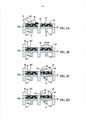
[004] As figuras 2A a 2F são vistas seccionais transversais das etapas envolvidas na(s) camada(s) de formação de um objeto 3D usando um exemplo do método de impressão 3D divulgado neste documento;[004] Figures 2A to 2F are cross-sectional views of the steps involved in the layer(s) of forming a 3D object using an example of the 3D printing method disclosed in this document;
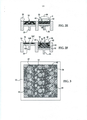
[005] A figura 3 é uma vista esquemática superior do material sinterizável no leito de fabricação da figura 2D, com um agente coalescente aplicado a uma parte do mesmo dentro de uma seção transversal da camada a ser formada e com um agente de modificação aplicado a uma outra parte do mesmo em um contorno de bordas;[005] Figure 3 is a schematic top view of the sinterable material in the fabrication bed of Figure 2D, with a coalescing agent applied to a part thereof within a cross section of the layer to be formed and with a modifying agent applied to another part of it in an outline of edges;
[006] A figura 4 é uma vista de frente em perspectiva de parte do material sinterizável no leito de fabricação da figura 2D, com o agente coalescente aplicado em uma parte do mesmo dentro da seção transversal do objeto 3D a ser formado e com o agente de modificação aplicado em uma outra parte do mesmo no contorno de bordas e fora da seção transversal do objeto 3D;[006] Figure 4 is a front perspective view of part of the sinterable material in the fabrication bed of Figure 2D, with the coalescing agent applied in a part thereof within the cross section of the 3D object to be formed and with the agent of modification applied to another part of it on the edge contour and outside the cross section of the 3D object;
[007] A figura 5 é uma vista isométrica simplificada de um exemplo de um sistema de impressão 3D que pode ser usado em um exemplo do método de impressão 3D tal como divulgado neste documento;[007] Figure 5 is a simplified isometric view of an example of a 3D printing system that can be used in an example of the 3D printing method as disclosed in this document;
[008] As figuras 6A-6F são fotografias de uma parte formada usando um exemplo do agente de modificação divulgado neste documento (figura 6A) e de partes comparativas formadas com agentes de modificação comparativos (figuras 6B-6F);[008] Figures 6A-6F are photographs of a portion formed using an example of the modifying agent disclosed in this document (figure 6A) and comparative portions formed with comparative modifying agents (figures 6B-6F);
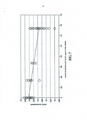
[009] A figura 7 é um gráfico de comprimento de dente versus gotas de agente de modificação; e[009] Figure 7 is a graph of tooth length versus modifier drops; and
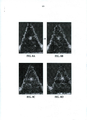
[010] As figuras 8A a 8D são fotografias de partes formadas usando quantidades diferentes de um agente de modificação.[010] Figures 8A to 8D are photographs of parts formed using different amounts of a modifying agent.
[011] Exemplos do método de impressão tridimensional (3D) divulgado neste documento utilizam processamento de área de luz. Durante processamento de área de luz, uma camada total de um material sinterizável é exposta à radiação, mas somente uma região selecionada do material sinterizável é fundida e endurecida para se tornar uma camada de um objeto 3D. Nos exemplos divulgados neste documento, um agente coalescente é seletivamente depositado em contato com a região selecionada do material sinterizável. Em algumas instâncias, o(s) agente(s) coalescente(s) é(são) capaz(es) de penetrar na camada do material sinterizável. Em outras instâncias, o agente coalescente pode permanecer na superfície do material sinterizável. Este agente coalescente é capaz de absorver radiação e converter a radiação absorvida em energia térmica, a qual por sua vez funde ou sinteriza o material sinterizável que está em contato com o agente coalescente. Isto faz com que o material sinterizável seja sinterizado, fundido, ligado, curado, etc. para formar a camada do objeto 3D. Quando o termo cura é usado, ele pode significar cura, sinterização, fusão, ligação ou coisa parecida.[011] Examples of the three-dimensional (3D) printing method disclosed in this document use light area processing. During light area processing, an entire layer of a sinterable material is exposed to radiation, but only a selected region of the sinterable material is fused and hardened to become a layer of a 3D object. In the examples disclosed in this document, a coalescing agent is selectively deposited in contact with the selected region of the sinterable material. In some instances, the coalescing agent(s) is (are) capable of penetrating the layer of sinterable material. In other instances, the coalescing agent may remain on the surface of the sinterable material. This coalescing agent is capable of absorbing radiation and converting the absorbed radiation into thermal energy, which in turn melts or sinters the sinterable material that is in contact with the coalescing agent. This causes the sinterable material to be sintered, cast, bonded, cured, etc. to form the 3D object layer. When the term healing is used, it can mean healing, sintering, fusing, bonding, or the like.
[012] Em algumas instâncias, constatou-se que a energia térmica pode se propagar para dentro de material sinterizável circundante. Isto pode resultar na subsequente solidificação de área(s)/parte(s) do material sinterizável que não era(m) pretendida(s) para ser(m) solidificada(s), e este efeito é referido neste documento como vazamento de coalescência. Vazamento de coalescência pode resultar, por exemplo, em uma redução na precisão dimensional total de objetos tridimensionais gerados e/ou de desenvolvimento de parte dimensional. Por exemplo, acuidade de borda pode ser indesejavelmente grosseira, indefinida, etc. Os efeitos de vazamento de coalescência podem ser gerenciados ao entregar um exemplo do agente de modificação divulgado neste documento para parte(s) apropriada(s) do material sinterizável antes de exposição à radiação. Exemplos do agente de modificação servem para reduzir o grau de coalescência, ou impedir coalescência de uma parte do material sinterizável para a qual o agente de modificação tenha sido entregue ou tenha penetrado. Nos exemplos divulgados neste documento, como aplicar o agente de modificação (em termos de posição e/ou quantidade) também pode ser determinado antes de aplicar realmente o agente de modificação. Isto capacita uma pessoa para aprimorar os efeitos do agente de modificação, para produzir partes mais precisas dimensionalmente, para melhorar o acabamento de superfície de partes e/ou para potencialmente reduzir ou eliminar a necessidade de técnicas de pós-processamento, as quais de outro modo são usadas para abordar preocupações similares.[012] In some instances, it has been found that thermal energy can propagate into surrounding sinterable material. This can result in the subsequent solidification of area(s)/part(s) of the sinterable material that were not intended to be solidified, and this effect is referred to in this document as coalescence leakage . Coalescence leakage can result, for example, in a reduction in the total dimensional accuracy of generated three-dimensional objects and/or dimensional part development. For example, edge acuity can be undesirably coarse, undefined, etc. Coalescence leakage effects can be managed by delivering an example of the modifying agent disclosed in this document to the appropriate part(s) of the sinterable material prior to radiation exposure. Examples of the modifying agent serve to reduce the degree of coalescence, or prevent coalescence of a portion of the sinterable material to which the modifying agent has been delivered or has penetrated. In the examples disclosed in this document, how to apply the modifying agent (in terms of position and/or quantity) can also be determined before actually applying the modifying agent. This enables a person to improve the effects of the modifying agent, to produce more dimensionally accurate parts, to improve the surface finish of parts, and/or to potentially reduce or eliminate the need for post-processing techniques, which would otherwise are used to address similar concerns.
[013] Um exemplo do método de impressão 3D 100 está representado na figura 1. É para ser entendido que cada uma das etapas do método 100 mostrado na figura 1 será discutida detalhadamente neste documento, e em algumas instâncias as figuras 2A a 2F e as figuras 3 e 4 serão discutidas em associação com a figura 1.[013] An example of the
[014] Tal como mostrado com o número de referência 102, o método 100 inclui aplicar um material sinterizável. Um exemplo desta etapa 102 está mostrado em seção transversal na figura 2A. No exemplo mostrado na figura 2A, uma camada 10 do material sinterizável 16 foi depositada, tal como será discutido com mais detalhes a seguir.[014] As shown with
[015] O material sinterizável 16 pode ser um pó, um líquido, uma pasta ou um gel. Exemplos do material sinterizável 16 incluem materiais termoplásticos semicristalinos com uma janela de processamento ampla de mais de 5 °C (isto é, a faixa de temperaturas entre o ponto de fusão e a temperatura de recristalização). Alguns exemplos específicos do material sinterizável 16 incluem poliamidas (por exemplo, náilon 11, náilon 12, náilon 6, náilon 8, náilon 9, náilon 66, náilon 612, náilon 812, náilon 912, etc.). Outros exemplos específicos do material sinterizável 16 incluem polietileno, tereftalato de polietileno (PET) e variação amorfa destes materiais. Ainda outros exemplos dos materiais sinterizáveis 16 adequados incluem poliestireno, poliacetais, polipropileno, policarbonato e misturas de quaisquer dois ou mais dos polímeros listados neste documento. Partículas de polímero de casca e núcleo destes materiais também podem ser usadas.[015] The
[016] Em um exemplo, o material sinterizável 16 inclui partículas de polímero dimensionadas de forma similar (por exemplo, partículas com o mesmo tamanho). Em um outro exemplo, o material sinterizável 16 inclui partículas de polímero dimensionadas diferentemente. Por exemplo, o material sinterizável 16 pode incluir partículas tendo dois ou mais tamanhos diferentes. No exemplo mostrado na figura 2A, o material sinterizável 16 inclui uma pluralidade das partículas de polímero 16A, 16B, 16C contendo pelo menos três tamanhos de partículas diferentes. Embora as partículas de polímero 16A, 16B, 16C de três tamanhos diferentes estejam mostradas na figura 2A, é para ser entendido que qualquer número adicional de tamanhos de partículas pode ser acrescentado.[016] In one example, the
[017] No exemplo mostrado na figura 2A, o tamanho médio da primeira partícula de polímero 16A é maior que o tamanho médio da segunda partícula de polímero 16B, e o tamanho médio da segunda partícula de polímero 16B é maior que o tamanho médio da terceira partícula de polímero 16C. O termo “tamanho”, tal como usado neste documento, se refere ao diâmetro de uma partícula esférica, ou o diâmetro médio de uma partícula não esférica (isto é, a média de múltiplos diâmetros através da partícula). De uma maneira geral, o tamanho médio de cada uma das primeiras, segundas e terceiras partículas 16A, 16B, 16C varia de 5 μm a cerca de 100 μm. Como um exemplo dos tamanhos diferentes para cada uma das partículas 16A, 16B, 16C, o tamanho médio da primeira partícula de polímero 16A pode ser maior que 50 μm, o tamanho médio da segunda partícula de polímero 16B pode estar entre 10 μm e 30 μm, e o tamanho médio da terceira partícula de polímero 16C pode ser igual ou menor que 10 μm.[017] In the example shown in Figure 2A, the average size of the
[018] A forma das partículas 16A, 16B, 16C também pode ser a mesma ou diferente. Em um exemplo, as partículas 16A, 16B, 16C têm formas esféricas ou quase esféricas. As partículas 16A, 16B, 16C que têm uma esfericidade de >0,84 são consideradas como sendo esféricas ou quase esféricas nos exemplos divulgados neste documento. Assim, quaisquer partículas 16A, 16B, 16C tendo uma esfericidade de <0,84 são não esféricas.[018] The shape of
[019] Uma ou mais das partículas 16A, 16B, 16C também podem ser modificadas fisicamente, de maneira que a topografia de superfície das partículas 16A, 16B, 16C é alterada e/ou modificada quimicamente.[019] One or more of the
[020] É para ser entendido que o material sinterizável 16 pode incluir, além das partículas de polímero 16A, 16B, e/ou 16C, um agente de carregamento, um ajudante de fluxo ou combinações dos mesmos.[020] It is to be understood that the
[021] Agente(s) de carregamento pode(m) ser acrescentado(s) para impedir tribocarregamento. Exemplos de agente(s) de carregamento adequado(s) incluem aminas alifáticas (que podem ser etoxiladas), amidas alifáticas, sais de amônio quaternário (por exemplo, cloreto de berrentrimônio ou cocamidopropil betaína), ésteres de ácido fosfórico, ésteres de polietilenoglicol ou polióis. Alguns agentes de carregamento disponíveis comercialmente adequados incluem HOSTASTAT® FA 38 (alquilamina etoxilada de base natural), HOSTASTAT® FE2 (éster de ácido graxo), e HOSTASTAT® HS 1 (sulfonato de alcano), cada um dos quais está disponível pela Clariant Int. Ltd.). Em um exemplo, o agente de carregamento é adicionado em uma quantidade variando de mais que 0% em peso a menos que 5% em peso com base na porcentagem total em peso das partículas de polímero.[021] Loading agent(s) may be added to prevent tribocharging. Examples of suitable loading agent(s) include aliphatic amines (which may be ethoxylated), aliphatic amides, quaternary ammonium salts (eg berentrimonium chloride or cocamidopropyl betaine), phosphoric acid esters, polyethylene glycol esters or polyols. Some suitable commercially available loading agents include HOSTASTAT® FA 38 (naturally based ethoxylated alkylamine), HOSTASTAT® FE2 (fatty acid ester), and HOSTASTAT® HS 1 (alkane sulfonate), each of which is available from Clariant Int . Ltd.). In one example, the filler is added in an amount ranging from more than 0% by weight to less than 5% by weight based on the total percentage by weight of the polymer particles.
[022] Ajudante(s) de fluxo pode(m) ser adicionado(s) para melhorar a fluxibilidade de revestimento do material sinterizável 16. Ajudante(s) de fluxo pode(m) ser particularmente desejável(eis) quando as partículas 16A, 16B e/ou 16C são menores que 25 μm em tamanho. O ajudante de fluxo melhora a fluxibilidade do material sinterizável 16 ao reduzir o atrito, o arrasto lateral e o desenvolvimento de tribocarregamento (ao aumentar a condutividade de partícula). Exemplos de ajudantes de fluxo adequados incluem trifosfato de cálcio (E341), celulose pulverizada (E460(ii)), estearato de magnésio (E470b), bicarbonato de sódio (E500), ferrocianeto de sódio (E535), ferrocianeto de potássio (E536), ferrocianeto de cálcio (E538), fosfato de osso (E542), silicato de sódio (E550), dióxido de silício (E551), silicato de cálcio (E552), trissilicato de magnésio (E553a), pó de talco (E553b), aluminossilicato de sódio (E554), silicato de potássio e alumínio (E555), aluminossilicato de cálcio (E556), bentonita (E558), silicato de alumínio (E559), ácido esteárico (E570), ou polidimetilsiloxano (E900). Em um exemplo, o ajudante de fluxo é adicionado em uma quantidade variando de mais que 0% em peso a menos que 5% em peso com base na porcentagem total em peso das partículas 16A, 16B e/ou 16C.[022] Flow helper(s) may be added to improve the coating flowability of the
[023] No exemplo mostrado na figura 2A, um sistema de impressão 12 para formar o objeto 3D inclui um leito de fornecimento 14 (incluindo um fornecimento do material sinterizável 16), um pistão de entrega 18, um rolete 20, um leito de fabricação 22 (tendo uma superfície de contato 25) e um pistão de fabricação 24. Cada um destes elementos físicos pode ser conectado operacionalmente a uma unidade central de processamento (não mostrada) do sistema de impressão 12. A unidade central de processamento (por exemplo, executando instruções legíveis por computador armazenadas em uma mídia de armazenamento tangível não transitório legível por computador) manipula e transforma dados representados como quantidades físicas (eletrônicas) dentro dos registradores e memórias da impressora a fim de controlar os elementos físicos para criar o objeto 3D. Os dados para a entrega seletiva do material sinterizável 16, do agente coalescente, etc. podem ser derivados de um modelo do objeto 3D a ser formado.[023] In the example shown in Figure 2A, a
[024] O pistão de entrega 18 e o pistão de fabricação 24 podem ser do mesmo tipo de pistão, mas são programados para deslocar em direções opostas. Em um exemplo, quando uma primeira camada do objeto 3D é para ser formada, o pistão de entrega 18 pode ser programado para empurrar uma quantidade predeterminada do material sinterizável 16 para fora da abertura no leito de fornecimento 14 e o pistão de fabricação 24 pode ser programado para deslocar na direção oposta à do pistão de entrega 18 a fim de aumentar a profundidade do leito de fabricação 22. O pistão de entrega 18 avançará o suficiente de tal maneira que, quando o rolete 20 empurra o material sinterizável 16 para o leito de fabricação 22 e para a superfície de contato 25, a profundidade do leito de fabricação 22 seja suficiente de tal maneira que uma camada 10 do material sinterizável 16 possa ser formada no leito 22. O rolete 20 é capaz de espalhar o material sinterizável 16 no leito de fabricação 22 para formar a camada 10, a qual é relativamente uniforme em espessura. Em um exemplo, a espessura da camada 10 varia de cerca de 90 μm a cerca de 110 μm, contudo camadas mais finas ou mais grossas também podem ser usadas.[024]
[025] É para ser entendido que o rolete 20 pode ser substituído por outras ferramentas, tais como uma lâmina que pode ser desejável para espalhar tipos diferentes de pós, ou por uma combinação de um rolete e uma lâmina.[025] It is to be understood that the
[026] Após a camada 10 do material sinterizável 16 ser depositada no leito de fabricação 22, a camada 10 é exposta ao calor (tal como mostrado no número de referência 104 na figura 1 e na figura 2B). Aquecimento é executado para preaquecer o material sinterizável 16, e assim é desejável que a temperatura de aquecimento fique abaixo do ponto de fusão do material sinterizável 16. Como tal, a temperatura selecionada dependerá do material sinterizável 16 que é usado. Como exemplos, a temperatura de aquecimento pode ser de cerca de 5 °C a cerca de 50 °C abaixo do ponto de fusão do material sinterizável. Em um exemplo, a temperatura de aquecimento varia de cerca de 50 °C a cerca de 350 °C. Em um outro exemplo, a temperatura de aquecimento varia de cerca de 150 °C a cerca de 170 °C. Em um outro exemplo, todo ou parte do preaquecimento pode ser executado enquanto o material sinterizável 16 ainda está no leito de fornecimento 14.[026] After the
[027] Preaquecimento da camada 10 do material sinterizável 16 pode ser executado usando qualquer fonte de calor adequada que exponha todo o material sinterizável 16 no leito de fabricação 22 ou no leito de fornecimento 14 ao calor. Exemplos da fonte de calor incluem uma fonte térmica de calor ou uma fonte de radiação de luz.[027] Preheating of
[028] Após preaquecer a camada 10, o agente coalescente é aplicado seletivamente em uma parte do material sinterizável 16 na camada 10, tal como mostrado no número de referência 106 na figura 1 e na figura 2C. Tal como ilustrado na figura 2C, o agente coalescente 28 pode ser dispensado de uma cabeça de impressão de jato de tinta 26. Embora uma única cabeça de impressão esteja mostrada na figura 2C, é para ser entendido que múltiplas cabeças de impressão podem ser usadas que se estendem sobre a largura do leito de fabricação 22. A cabeça de impressão 26 pode ser ligada a uma posição XY de deslocamento ou a um carro translacional (nenhum dos quais está mostrado) que desloca a cabeça de impressão 26 adjacente ao leito de fabricação 22 a fim de depositar o agente coalescente 28 em área(s) desejável(eis).[028] After preheating the
[029] A cabeça de impressão 26 pode ser programada para receber comandos da unidade central de processamento e para depositar o agente coalescente 28 de acordo com um padrão de uma seção transversal para a camada do objeto 3D que é para ser formado. Tal como usado neste documento, a seção transversal da camada do objeto a ser formado se refere à seção transversal que é paralela à superfície de contato 25. A cabeça de impressão 26 aplica seletivamente o agente coalescente 28 sobre essa(s) parte(s) 44 da camada 10 que é(são) para ser fundida(s) para se tornar a primeira camada do objeto 3D. Como um exemplo, se a primeira camada for para ser modelada tal como um cubo ou cilindro, o agente coalescente 28 será depositado em um padrão quadrangular ou em um padrão circular (a partir de uma vista superior), respectivamente, sobre pelo menos uma parte 44 da camada 10 do material sinterizável 16. No exemplo mostrado na figura 2C, o agente coalescente 28 é depositado em um padrão quadrangular sobre a parte 44 da camada 10 e não fora da parte 44.[029] The
[030] Alguns exemplos dos agentes coalescentes adequados 28 são dispersões à base de água incluindo um agente de ligação de absorção de radiação (isto é, um material ativo). O agente ativo pode ser um absorvedor de luz infravermelha, um absorvedor de luz infravermelha próxima ou um absorvedor de luz visível. Como um exemplo, o agente coalescente 28 pode ser uma formulação do tipo tinta incluindo negro de fumo como o material ativo. Um exemplo desta formulação do tipo tinta é conhecido comercialmente como CM997A disponível pela Hewlett-Packard Company. Exemplos de tintas incluindo realçadores de luz visível como o agente ativo são tinta colorida à base de corante e tinta colorida à base de pigmento. Exemplos de tintas coloridas à base de pigmentos incluem as tintas disponíveis comercialmente CE039A e CE042A da Hewlett-Packard Company.[030] Some examples of suitable coalescing
[031] A natureza aquosa do agente coalescente 28 capacita o agente coalescente 28 para penetrar, pelo menos parcialmente, na camada 10 do material sinterizável 16. O material sinterizável 16 pode ser hidrofóbico, e a presença de um cossolvente e/ou de um surfactante no agente coalescente 28 pode ajudar na obtenção de comportamento de molhamento desejável.[031] The aqueous nature of the coalescing
[032] É para ser entendido que um único agente coalescente 28 pode ser aplicado seletivamente para formar a camada do objeto 3D, ou que múltiplos agentes coalescentes 28 podem ser aplicados seletivamente para formar a camada do objeto 3D.[032] It is to be understood that a
[033] Antes, concorrentemente ou após o agente coalescente 28 ser aplicado seletivamente sobre a(s) parte(s) desejada(s) 44, o agente de modificação é aplicado seletivamente sobre parte(s) diferente(s) do material sinterizável 16, tal como mostrado no número de referência 110 na figura 1. Um exemplo da aplicação seletiva do agente de modificação está mostrado esquematicamente na figura 2D, onde número de referência 29 representa o agente de modificação e o número de referência 42 representa as outras partes do material sinterizável 16 às quais o agente de modificação 29 é aplicado seletivamente.[033] Before, concurrently or after the coalescing
[034] Pode ser desejável controlar a quantidade e/ou posicionamento do agente de modificação 29 que é aplicado ao material sinterizável 16. O agente de modificação 29 age como um refrigerante, o qual efetivamente remove energia e mantém o material sinterizável 16 em uma temperatura que impede cura ou retarda a sinterização, derretimento, fusão e/ou cura do material sinterizável 16. Como tal, antes de realmente aplicar seletivamente o agente de modificação 29, o método 100 inclui adicionalmente determinar como aplicar seletivamente o agente de modificação 29. Isto está mostrado no número de referência 108 na figura 1.[034] It may be desirable to control the amount and/or positioning of the modifying
[035] A determinação para verificar como aplicar seletivamente o agente de modificação 29 pode incluir determinar onde aplicar o agente de modificação 29 e/ou determinar quanto aplicar o agente de modificação 29. Estas determinações podem ser feitas usando uma característica de difusão térmica do material sinterizável 16, uma camada a ser formada do material sinterizável 16 (isto é, a camada ou parte sinterizada) ou combinações das mesmas. A característica de difusão térmica pode ser uma escala de tempo/tempo característico de difusão térmica, uma escala de comprimento/comprimento característico de difusão térmica, um perfil de temperaturas e/ou um perfil de energia.[035] The determination to verify how to selectively apply the modifying
[036] Tempos e comprimentos característicos se referem ao tempo aproximado ou distância exigida para um sistema se recuperar de uma perturbação. Frequentemente eles são definidos como o tempo ou distância para uma perturbação ser reduzido para 1/e (~37%) da perturbação inicial. Na prática, frequentemente eles são usados para significar o tempo ou distância em que uma perturbação tem um efeito significativo. A escala de tempo de difusão térmica de uma maneira geral se refere ao tempo gasto para o material sinterizável estabilizar (aproximar de seu valor de equilíbrio) em temperatura após energia ter sido adicionada ou removida de uma área adjacente de material. A escala de comprimento de difusão térmica de uma maneira geral se refere à distância a partir da borda de parte ou superfície de construção que experimenta um aumento de temperatura significativo por causa da presença do material sinterizado quente. Como exemplos, a distância pode ser horizontal ou vertical com relação à localização do material sinterizado. Exemplos de uma mudança ou aumento de temperatura significativo incluem i) uma elevação de temperatura de cerca de 25% da diferença entre a temperatura de parte/camada sinterizada e a temperatura de material sinterizável circundante, ou ii) 25% da diferença entre a temperatura normal do material sinterizável circundante 16 e a temperatura de fusão do material sinterizável 16. As escalas de tempo e/ou de comprimento de difusão térmica podem ser medidas empiricamente, ou derivadas de respectivos coeficientes de difusão térmica ou diferenças de temperatura no sistema. Os coeficientes de difusão térmica propriamente ditos podem ser determinados empiricamente ou estimados a partir de valores de materiais similares ou por meio de métodos de modelagem química.[036] Characteristic times and lengths refer to the approximate time or distance required for a system to recover from a disturbance. They are often defined as the time or distance for a disturbance to be reduced to 1/e (~37%) of the initial disturbance. In practice they are often used to signify the time or distance at which a disturbance has a significant effect. The thermal diffusion time scale generally refers to the time taken for the sinterable material to stabilize (approach its equilibrium value) in temperature after energy has been added to or removed from an adjacent area of material. The thermal diffusion length scale generally refers to the distance from the edge of a part or building surface that experiences a significant temperature rise because of the presence of the hot sintered material. As examples, the distance can be horizontal or vertical with respect to the location of the sintered material. Examples of a significant temperature change or increase include i) a temperature rise of about 25% of the difference between the sintered part/layer temperature and the temperature of the surrounding sinterable material, or ii) 25% of the difference between the normal temperature of the surrounding
[037] O perfil de temperaturas e/ou de energia de uma maneira geral se refere às diferenças de temperatura e/ou de energia exibidas pelo material sinterizável 16 ou pela parte/camada sinterizada com ou sem um agente 28 e/ou 29 aplicado à mesma. Como exemplos, estas diferenças podem ser observadas antes de exposição à radiação (por exemplo, por causa de evaporação de agente de modificação) ou após exposição à radiação (por exemplo, por causa de migração de energia). O perfil de temperaturas e/ou perfil de energia podem ser gerados usando o modelo térmico, ou podem ser uma estimativa de um perfil de temperaturas ou de energia. Tal como será descrito com mais detalhes a seguir, a estimativa do perfil de temperaturas ou de energia pode ser baseada na manipulação dos dados de imagens usados para formar as camadas de partes 3D. Calcular a variação local a partir de valores médios da região circundante fornece uma estimativa grosseira das diferenças de temperatura e/ou de energia na camada/parte sinterizada onde o agente de coalescência 28 é aplicado e não aplicado.[037] The temperature and/or energy profile in general refers to the temperature and/or energy differences exhibited by the
[038] Em alguns dos exemplos divulgados neste documento, a quantidade e/ou posição apropriadas do agente de modificação 29 podem ser determinadas usando um modelo térmico dependente de tempo do processo de sinterização. Em um exemplo, o modelo térmico propriamente dito pode ser usado para calcular diretamente a quantidade de agente de modificação e/ou identificar a posição de agente de modificação. Em um outro exemplo, o modelo térmico é usado para gerar um perfil de temperaturas ou de energia, o qual pode ser usado por um algoritmo de correção para gerar um padrão (por exemplo, localização e/ou quantidade) para aplicar o agente de modificação 29. Ainda em outros exemplos, um ou mais modelos térmicos podem ser usados para identificar escalas de tempo e/ou de comprimento típicas de difusão térmica. Acredita-se que a escala de comprimento e/ou a escala de tempo típicas podem então ser usadas para calcular a quantidade de agente de modificação e/ou determinar a posição de agente de modificação, sem exigir modelagem total da geometria exata do objeto 3D a ser formado. Em outros exemplos divulgados neste documento, a quantidade e/ou a posição apropriadas do agente de modificação 29 podem ser determinadas empiricamente.[038] In some of the examples disclosed in this document, the appropriate amount and/or position of the modifying
[039] Nos exemplos envolvendo o modelo térmico dependente de tempo do processo de sinterização, é para ser entendido que o modelo térmico pode ser gerado usando um método de modelagem computacional. O método de modelagem computacional é executado por um computador (incluindo componentes de hardware tais como um processador) desempenhando/executando instruções legíveis por computador que são armazenadas em uma mídia tangível não transitória legível por computador. Um exemplo do software de modelagem computacional é o Abaqus FEA versão 6.13. Em qualquer um dos exemplos divulgados neste documento, a mídia legível por computador pode incluir qualquer uma de muitas mídias físicas tais como, por exemplo, mídias eletrônicas, magnéticas, óticas, eletromagnéticas ou semicondutoras. Exemplos mais específicos de mídias legíveis por computador adequadas incluem unidades rígidas, uma memória de acesso aleatório (RAM), uma memória somente de leitura (ROM), uma memória somente de leitura programável e apagável (EPROM), ou um CD, DVD portátil, ou unidade flash.[039] In the examples involving the time-dependent thermal model of the sintering process, it is to be understood that the thermal model can be generated using a computational modeling method. The computational modeling method is performed by a computer (including hardware components such as a processor) performing/executing computer-readable instructions that are stored on computer-readable non-transient tangible media. An example of computational modeling software is Abaqus FEA version 6.13. In any of the examples disclosed in this document, computer readable media can include any of many physical media such as, for example, electronic, magnetic, optical, electromagnetic or semiconductor media. More specific examples of suitable computer readable media include hard drives, a random access memory (RAM), a read-only memory (ROM), a programmable and erasable read-only memory (EPROM), or a portable CD, DVD, or flash drive.
[040] É para ser entendido que o método de modelagem computacional ou qualquer um dos métodos baseados em computador para determinar como aplicar o agente de modificação 29 pode ser virtualizado e configurado em um Computador em Nuvem (isto é, em um ambiente de computação baseado em Internet). Por exemplo, o equipamento de computação pode ser acessado como um serviço de plataforma em nuvem, ou PaaS (Plataforma como um Serviço), utilizando infraestrutura de nuvem em vez de hospedar equipamento de computação em um prédio físico. A infraestrutura de nuvem, conhecida como IaaS (Infraestrutura como um Serviço), tipicamente utiliza um ambiente de virtualização de plataforma como um serviço, o que pode incluir componentes tais como o processador, base de dados, servidor e outro equipamento de computação.[040] It is to be understood that the computational modeling method or any of the computer-based methods for determining how to apply the modifying
[041] O computador recebe características (por exemplo, como entradas de um usuário) que são suficientes para construir o modelo térmico. Estas características dizem respeito ao material sinterizável 16 sendo modelado (por exemplo, o tipo de pó, condutividade térmica em temperaturas diferentes, capacidade térmica e densidade), ao número de camadas, à espessura das camadas, ao tipo de agente de coalescência 28 sendo modelado, a uma temperatura estabelecida do leito de fabricação 22 e ao tempo para construir uma camada particular. Em um exemplo, a densidade, capacidade térmica e a difusibilidade térmica são fornecidas para ambos material sinterizável não sinterizado 16 e o material sinterizado. A mudança de capacidade térmica entre o material sinterizável não sinterizado 16 e o material sinterizado pode ser amplamente por causa da mudança de densidade entre os materiais, e assim um único valor de capacidade térmica pode ser adequado. Ainda outros exemplos de características que podem ser introduzidas no computador são a energia liberada quando a camada se solidifica a partir de um estado fundido, a temperatura na qual o material sinterizável 16 e o agente coalescente 28 são entregues para o leito de fabricação 22, e/ou as entradas ou perdas de energia esperadas da(s) superfície(s) de borda do volume de construção. Para alguns materiais sinterizáveis 16, qualquer um ou todos estes parâmetros/características podem variar com temperatura. Pode ser desejável incluir o comportamento dependente de temperatura, por exemplo, se os parâmetros mudarem mais que 10% dentro da faixa de temperaturas experimentada durante o processo de construção.[041] The computer receives characteristics (eg, as input from a user) that are sufficient to build the thermal model. These characteristics relate to the
[042] As características introduzidas também podem incluir as diferenças em temperatura, capacidade térmica específica e difusibilidade térmica entre o material sinterizável 16 na parte 44 (a ser curada) e na parte 42 (a ser não curada). Por exemplo, uma entrada adequada pode descrever a diferença em radiação convertida em calor pelas regiões não sinterizadas (por exemplo, a parte 42) versus a(s) parte(s) 44 com o agente coalescente 28 que converterá(ão) mais da radiação em calor. Esta entrada pode ser uma medição empírica da diferença de temperatura entre a(s) parte(s) curada(s)/sinterizada(s) 44 e a(s) parte(s) não curada(s)/não sinterizada(s) 42. Outras características gerais podem incluir uma maior capacidade térmica específica e uma menor difusibilidade térmica na(s) parte(s) 42 do que na(s) parte(s) 44.[042] The characteristics introduced may also include the differences in temperature, specific heat capacity and thermal diffusivity between the
[043] Todas estas características são usadas pelo computador (executando um programa de software adequado) para construir um modelo térmico da camada ou objeto. Uma análise de elementos finitos ou outra técnica de modelagem pode ser usada para identificar os gradientes térmicos que se desenvolvem em volta da camada ou do objeto ao longo de uma escala de tempo de interesse. Em um exemplo, a escala de tempo de interesse é o tempo exigido para construir uma ou várias camadas. Os gradientes térmicos que se desenvolvem em volta da camada/parte ao longo da escala de tempo de interesse identificam a escala de comprimento de difusão térmica para um modelo térmico particular. A escala de tempo de difusão térmica pode ser determinada ao gerar um modelo térmico com números diferentes de camadas de partes que devem ser formadas, e identificar o modelo que deve ser executado após a adição de uma camada de material para convergência do modelo térmico para predições estáveis em uma camada particular.[043] All these features are used by the computer (running a suitable software program) to build a thermal model of the layer or object. A finite element analysis or other modeling technique can be used to identify thermal gradients that develop around the layer or object over a time scale of interest. In one example, the time scale of interest is the time required to build one or multiple layers. Thermal gradients that develop around the layer/part along the time scale of interest identify the thermal diffusion length scale for a particular thermal model. The thermal diffusion time scale can be determined by generating a thermal model with different numbers of layers of parts that must be formed, and identifying the model that must be run after adding a layer of material for convergence of the thermal model for predictions stable in a particular layer.
[044] As temperaturas nas proximidades da camada ou do objeto enquanto ele está sendo fabricado podem ser estimadas com base no modelo (por exemplo, usando o(s) gradiente(s) térmico(s)). Como tal, o modelo térmico é usado para determinar a localização e sincronismo de fluxos de calor na camada ou objeto sendo construído e em volta dele. Mais particularmente, o excesso de temperatura (ΔT) do material sinterizado 16 na parte 42 (onde cura não é desejável) que está acima da temperatura estabelecida do leito de fabricação 22 representa excesso de energia evoluída da camada ou objeto. O excesso de temperatura pode ser determinado ao subtrair a temperatura estabelecida do leito de fabricação da temperatura do material sinterizado 16 na parte 42 de acordo com o modelo térmico ou uma medição empírica (feita usando um dispositivo de medição de temperatura de alta resolução, tal como uma câmera IR).[044] Temperatures in the vicinity of the layer or object while it is being manufactured can be estimated based on the model (eg using the thermal gradient(s)). As such, the thermal model is used to determine the location and timing of heat fluxes in and around the layer or object being constructed. More particularly, the excess temperature (ΔT) of the
[045] Esta diferença de temperatura (ΔT) pode ser convertida em uma quantidade de excesso de energia usando a capacidade térmica específica (CpSM), densidade (denSM) e volume (volSM) do material sinterizável não sinterizado 16, tal como mostrado na equação 1: Excesso de Energia = CpSM * volSM * denSM * ΔT (equação 1) O excesso de energia para a parte total 42 pode ser identificado. Como tal, um mapa de excesso de energia em volta da camada ou do objeto pode ser gerado por meio deste método.[045] This temperature difference (ΔT) can be converted into an amount of excess energy using the specific thermal capacity (CpSM), density (denSM) and volume (volSM) of the unsintered
[046] O excesso de energia é equivalente a uma quantidade de energia a ser removida (isto é, energia removida) pelo agente de modificação 29. Como tal, o excesso de energia pode ser convertido em uma quantidade do agente de modificação 29 que é apropriada para remover esta quantidade de energia. Usando o mapa de excesso de energia e os valores de quantidades de agente de modificação convertidas, um mapa das quantidades desejadas do agente de modificação 29 em volta da camada ou do objeto pode ser gerado. Como tal, com este exemplo, tanto a posição quanto a quantidade do agente de modificação 29 a ser usado podem ser determinadas.[046] The excess energy is equivalent to an amount of energy to be removed (ie, energy removed) by the modifying
[047] A conversão de energia em excesso/removida para quantidade de agente de modificação pode ser realizada usando a capacidade térmica específica (CpMA) do agente de modificação 29 para elevar sua temperatura da temperatura de aplicação (Tapl-MA) para o ponto de ebulição (Tebu-MA), mais o calor de vaporização (Hvap-MA) do agente de modificação 29. A conversão do excesso de energia na quantidade do agente de modificação 29 está mostrada na equação 2 ou 3: Energia Removida = CpMA * (Tebu-MA - Tapi-MA) + Hvap-Ma) * vol. de agente de modificação (equação 2) Vol. de agente de modificação = (Energia Removida)/(CpMA * (Tebu-MA - Tapl-MA) + Hvap-MA)) (equação 3)[047] The conversion of excess/removed energy to amount of modifying agent can be performed using the specific thermal capacity (CpMA) of modifying
[048] A temperatura de aplicação (Tapl-MA) do agente de modificação 29 pode ser a temperatura ambiente (de cerca de 18 °C a cerca de 22°C), uma temperatura controlada pela cabeça de impressão 26’ (ver a figura 2D) ou por outro dispositivo de aplicação (por exemplo, uma temperatura de aquecimento ou de operação de uma cabeça de impressão de jato de tinta), ou uma temperatura típica que o agente de modificação 29 alcança, à medida que ele é entregue para o leito de fabricação aquecido 22 do sistema 12. A soma dos termos de energia de aquecimento e de vaporização multiplicada pelo volume do fluido de modificação 29 é igual à energia total que o agente de modificação 29 removerá do sistema (isto é, a energia removida).[048] The application temperature (Tapl-MA) of the modifying
[049] É para ser entendido que, após o agente de modificação 29 ser aplicado ao material sinterizável aquecido 16, o agente de modificação 29 evapora e remove energia do material sinterizável 16. A evaporação pode ser na ordem de alguns décimos de um segundo, o que pode resultar em remoção significativa antes da aplicação da energia de cura (isto é, a radiação R, ver a figura 2E). Isto pode criar uma região fria para a qual energia migrará ao longo do tempo. Em outras palavras, a energia pode difundir de volta para a(s) parte(s) 42 que foi(foram) resfriada(s) pelo agente de modificação 29 (resultando em uma perda de resfriamento local). Esta migração secundária de energia (em termos de quantidade) pode ser estimada por meio de métodos de modelagem ou empíricos. Então, a quantidade de energia a ser removida (isto é, energia removida na equação 3 acima) pode ser aumentada por esta quantidade para compensar este efeito.[049] It is to be understood that after the modifying
[050] Para determinar a quantidade de energia resultando de migração secundária usando o modelo térmico, pode ser permitido que o modelo térmico seja executado com um tempo de atraso desejado após a aplicação do agente de modificação 29. O agente de modificação 29 pode ser incorporado ao modelo como uma remoção simples de energia em um instante no tempo, ou como um submodelo envolvendo evaporação e outros comportamentos de fluido.[050] To determine the amount of energy resulting from secondary migration using the thermal model, the thermal model can be allowed to run with a desired delay time after applying modifying
[051] Para determinar a quantidade de energia resultando de migração secundária usando um método empírico, as medições de temperatura descritas no método empírico a seguir podem ser feitas seguintes a um atraso após a aplicação de radiação.[051] To determine the amount of energy resulting from secondary migration using an empirical method, the temperature measurements described in the empirical method below can be made following a delay after the application of radiation.
[052] Um exemplo de um método empírico para determinar como aplicar o agente de modificação 29 será descrito agora. A partir deste método empírico, uma tabela da quantidade de agente de modificação versus mudança de temperatura efetuada pela quantidade de agente de modificação 29 pode ser construída. A mudança de temperatura se refere a uma diferença entre a temperatura do material sinterizável 16 (sem ter qualquer agente coalescente 28 ou agente de modificação 29 no mesmo) após ser exposto à radiação e à temperatura do material sinterizável 16 (tendo o agente de modificação 29 no mesmo) após ser exposto à radiação. Neste exemplo, quaisquer medições de temperatura podem ser executadas com qualquer dispositivo de temperatura adequado, tal como uma câmera infravermelha (IR), um sensor de temperatura IR ou termopar de massa baixa.[052] An example of an empirical method for determining how to apply
[053] Neste exemplo do método, a tabela pode ser construída ao aplicar quantidades diferentes do agente de modificação 29 em respectivas áreas do material sinterizável 16, e não aplicar o agente de modificação 29 em uma área do material sinterizável 16. O material sinterizável total 16 pode então ser exposto à radiação. A área sem o agente de modificação 29 exposta à radiação é referida como uma área de referência, e as áreas com as quantidades diferentes do agente de modificação 29 expostas à radiação são referidas como áreas de testes. A temperatura da área de referência e das áreas de testes podem ser medidas. Cada área de teste que recebeu agente de modificação após receber radiação deve ter uma temperatura menor que a da área de referência. Para uma área de teste particular, a redução de temperatura quando comparada com a da área de referência é o efeito da quantidade associada de agente de modificação. As mudanças de temperatura podem ser calculadas e correlacionadas com as quantidades diferentes do agente de modificação 29 que são usadas para gerar a tabela. Em aplicações de impressão 3D subsequentes usando o mesmo ou um material sinterizável similar 16 e o agente de modificação 29, a tabela pode ser referenciada para determinar a quantidade do agente de modificação 29 a usar para efetuar uma mudança de temperatura desejada.[053] In this example method, the table can be constructed by applying different amounts of the modifying
[054] Ainda em um outro exemplo, a escala de comprimento de difusão térmica pode ser determinada empiricamente. Neste exemplo, uma camada/parte de teste é usada. A camada/parte de teste é constituída do mesmo material sinterizável 16 e do mesmo agente coalescente 28 que é para ser usado para o objeto/camada 3D real. Para a camada/parte de teste, o agente coalescente 28 pode ser aplicado em uma geometria simples, tal como um quadrado, ou em geometria similar à de objetos 3D reais. O tamanho da parte de teste deve ser grande quando comparado com a escala de comprimento determinada de difusão térmica, por exemplo, pelo menos três vezes o tamanho. Em um exemplo, meia polegada (12,7 milímetros) pode ser um tamanho suficiente. Entretanto, se a escala de comprimento determinada for maior que 1/3 do tamanho de objeto, o teste deve ser refeito usando um tamanho de parte de teste maior. O agente de modificação 29 não é usado para a camada/parte de teste. Após aplicação do agente coalescente 28 e exposição à radiação, a camada/parte de teste é formada. A posição do material coalescente 28 ao formar a camada/parte de teste é comparada com a extensão real do material 16 sinterizando na camada/parte de teste. Durante esta comparação, a camada/parte de teste é examinada com relação a qualquer material sinterizado indesejável localizado além/fora do contorno de bordas do material coalescente aplicado 28. O comprimento do material sinterizado indesejável é medido. Este valor, ou este valor multiplicado por um fator de correção escalar, é a escala de comprimento estimada que pode ser usada em outros exemplos. Se a geometria de objeto 3D real tiver sido usada, a região de material sinterizado indesejável pode ser usada para estimar a localização para o agente de modificação 29 durante formação do objeto/camada 3D real.[054] In yet another example, the thermal diffusion length scale can be determined empirically. In this example, a test layer/part is used. The test layer/part is made up of the
[055] Ao formar subsequentemente o objeto/camada 3D real, o agente coalescente 28 pode ser aplicado na mesma posição e o agente de modificação 29 pode ser aplicado ao longo da escala de comprimento estimada. O uso do agente de modificação 29 próximo ao contorno de bordas 27 pode reduzir a temperatura do material sinterizável 16 dentro da(s) parte(s) 42 nas bordas da camada a ser formada, mas também pode reduzir a qualidade de sinterização ou fusão dentro da(s) parte(s) 44 ao longo do contorno de bordas 27. Esta perda de energia dentro da seção transversal da camada pode ser compensada ao aumentar a quantidade do agente coalescente 28 dentro da(s) parte(s) 44.[055] When subsequently forming the actual 3D object/layer, coalescing
[056] Ainda adicionalmente, o modelo térmico também pode predizer que o interior de uma camada/parte está muito quente (isto é, excesso de energia está presente). Este aumento de energia dentro da seção transversal da camada/parte pode ser compensado ao diminuir a quantidade do agente coalescente 28 dentro da(s) parte(s) 44 e/ou aumentar uma quantidade do agente de modificação 29 dentro da(s) parte(s) 44. Neste exemplo, a quantidade do agente de modificação 29 a adicionar pode ser calculada usando a equação 3, exceto que nesta instância a energia removida é o excesso de energia na localização particular dentro da seção transversal da camada/parte.[056] Still additionally, the thermal model can also predict that the inside of a layer/part is very hot (ie, excess energy is present). This increase in energy within the cross section of the layer/part can be compensated for by decreasing the amount of coalescing
[057] A quantidade aumentada ou diminuída do agente coalescente 28 pode ser determinada em um modo análogo a determinar quanto agente de modificação 29 aplicar seletivamente. Por exemplo, os valores de temperatura delta do modelo térmico podem ser convertidos em uma quantidade de energia e, usando uma tabela modelada ou empírica de quantidade de agente coalescente versus energia absorvida, a quantidade adicional de agente coalescente 28 pode ser determinada.[057] The increased or decreased amount of coalescing
[058] Para concentrações do agente coalescente 28 baixas o suficiente em que a Lei de Beer (absorção A = εlc = coeficiente de absorção * comprimento de caminho * concentração) se aplica, a quantidade do agente coalescente 28 exigida terá uma relação linear com a mudança de temperatura desejada. Para concentrações mais altas do agente coalescente 28, a eficiência de absorção pode ser reduzida, e agente coalescente 28 adicional pode ser necessário para efetuar a mudança desejada. Isto pode ser modelado ou determinado empiricamente ao comparar temperaturas após radiação ser aplicada às partes do material sinterizável 16 coberto com quantidades diferentes de agente coalescente. Uma solução baseada em modelo pode precisar incorporar o efeito de resfriamento de evaporar quaisquer solventes voláteis dispensados como parte do agente coalescente 28, além do comportamento de absorção do agente coalescente 28, e perdas radioativas ou convectivas da superfície do leito de fabricação 22.[058] For low enough coalescing
[059] Em outros exemplos, o computador pode incluir um algoritmo de correção. Usando o algoritmo de correção, uma imagem modificada pode ser gerada para corrigir os dados em função dos efeitos de difusão térmica para cada imagem de camada do objeto 3D a ser formado.[059] In other examples, the computer may include a correction algorithm. Using the correction algorithm, a modified image can be generated to correct the data as a function of thermal diffusion effects for each layer image of the 3D object to be formed.
[060] De uma maneira geral, o algoritmo de correção utiliza informação de forma 3D para a imagem de camada e um perfil de temperaturas/energia associado com a forma 3D para gerar um padrão (incluindo informação de localização e/ou de quantidade) para aplicar o agente de modificação 29. A informação de forma 3D pode incluir informação a respeito de uma camada, de várias camadas ou da parte total, e também pode incluir valor(s) que é(são) indicativo(s) da aplicação seletiva do agente coalescente 28. Por exemplo, pode existir uma quantidade variando espacialmente do agente coalescente 28 que é usada no modelo térmico ou usada na manipulação da informação de forma 3D.[060] Generally speaking, the correction algorithm uses 3D shape information for the layer image and a temperature/energy profile associated with the 3D shape to generate a pattern (including location and/or quantity information) to apply the modifying
[061] Nestes exemplos, a informação de forma 3D pode ser fornecida para o modelo térmico e o perfil de temperaturas/energia pode ser gerado automaticamente. Alternativamente, a manipulação da informação de forma 3D (descrita a seguir) pode ser usada para gerar uma estimativa do perfil de temperaturas/energia (na forma de um mapa de variação de temperatura/energia local) sem usar um modelo térmico.[061] In these examples, 3D shape information can be provided for the thermal model and the temperature/energy profile can be generated automatically. Alternatively, manipulating the information in 3D form (described below) can be used to generate an estimate of the temperature/energy profile (in the form of a local energy/temperature variation map) without using a thermal model.
[062] Em um exemplo usando manipulação da informação de forma 3D, o mapa de variação de temperatura/energia local na região desenvolvida pode ser construído a partir da imagem de camada 3D com base em uma técnica de cálculo de média espacial. No exemplo seguinte é assumido que a imagem de camada original é composta, ou pode ser convertida em dados com valores positivos descrevendo a(s) parte(s) 44 que deve(m) receber o agente coalescente 28, e um valor de zero descrevendo a(s) parte(s) 42 não recebendo o agente coalescente 28. É para ser entendido, entretanto, que os valores podem ser comutados, se desejável. Estas convenções de valores são usadas para o propósito de clareza neste exemplo. É para ser entendido que outras convenções de valores e operações matemáticas podem ser empregadas para alcançar o resultado pretendido.[062] In an example using 3D shape information manipulation, the local temperature/energy variation map in the developed region can be constructed from the 3D layer image based on a spatial averaging technique. In the following example it is assumed that the original layer image is composite, or can be converted to data with positive values describing the part(s) 44 that should receive the coalescing
[063] O raio da imagem de camada na qual uma média pode ser obtida pode ser determinado por meio do comprimento característico de difusão térmica descoberto no modelo térmico ou por meio de medição empírica de crescimento de parte em excesso. Esta medição empírica pode ser executada ao construir partes de comprimentos nominais usando o agente coalescente 28, e representar graficamente o erro dimensional após exposição à radiação (quando o agente de modificação 29 não é usado) versus o tamanho nominal. Neste exemplo, a intercessão da melhor linha de encaixe com o eixo Y (parte de comprimento 0) deve ser aproximadamente o comprimento característico. Esta medição empírica também pode ser executada tal como descrito anteriormente para a escala de comprimento (por exemplo, com a camada/parte de teste).[063] The radius of the layer image on which an average can be obtained can be determined by means of the characteristic length of thermal diffusion discovered in the thermal model or by means of empirical measurement of excess part growth. This empirical measurement can be performed by constructing parts of nominal lengths using coalescing
[064] Um mapa grosseiro de temperatura local/teor de energia pode ser calculado em cada localização (isto é, pixel) ao calcular a média dos valores de todos os pixels dentro do raio dessa localização. Cálculo de média pode ser executado usando uma função Gaussiana de cálculo de média, ou alguma outra função de cálculo de média adequada. A diferença entre o valor de pixel original e o valor médio calculado de todos os pixels dentro do raio especificado indica a quantidade de desequilíbrio de energia que pode ser corrigida para usar o agente de modificação 29 nessa localização de pixel. Mais particularmente, quando o valor de pixel médio calculado excede o valor de pixel real (por exemplo, uma diferença negativa), isto indica que o resfriamento pelo agente de modificação 29 é desejável. Quando o valor de pixel real excede o valor de pixel médio calculado (por exemplo, uma diferença positiva), isto indica que o agente de modificação 29 não deve ser usado, ou que uma quantidade adicional do agente coalescente 28 pode ser aplicada à localização. O valor de diferença positivo pode ser acrescentado diretamente ao valor de pixel original para modificar a quantidade do agente coalescente 28, multiplicado por um fator de ajuste escalar, ou usado como o índice em uma tabela de pesquisa para descobrir uma quantidade para adicionar ao valor de pixel original. Para o agente de modificação 29, o valor de diferença negativo pode ser usado diretamente, multiplicado por um fator de ajuste escalar, ou usado como o índice em uma tabela de pesquisa para descobrir uma quantidade adequada. A partir dos valores de diferenças, o padrão para aplicar o agente coalescente 28 e/ou o agente de modificação 29 pode ser produzido.[064] A rough map of local temperature/energy content can be calculated at each location (ie pixel) by averaging the values of all pixels within the radius of that location. Averaging can be performed using a Gaussian averaging function, or some other suitable averaging function. The difference between the original pixel value and the average calculated value of all pixels within the specified radius indicates the amount of energy imbalance that can be corrected by using the modifying
[065] É para ser entendido que o algoritmo de correção pode resultar em diferenças tanto positivas quanto negativas em partes diferentes da imagem de camada. Nestas instâncias, as quantidades para ambos agente de modificação 29 e agente coalescente 28 podem ser ajustadas. Quando todas as diferenças positivas são obtidas, o uso do agente de modificação 29 pode não ser desejável.[065] It is to be understood that the correction algorithm can result in both positive and negative differences in different parts of the layer image. In these instances, amounts for both modifying
[066] A imagem corrigida final (isto é, o resultado de subtração de imagem média calculada ou a imagem modificada por resultados de modelo térmico) pode ser sombreada, isto é, convertida em um padrão espacial de pontos correspondendo à informação de intensidade na imagem corrigida.[066] The final corrected image (ie the calculated average image subtraction result or the image modified by thermal model results) can be shaded, ie, converted to a spatial pattern of dots corresponding to the intensity information in the image corrected.
[067] Dependendo do tamanho relativo do tempo de fabricação de camada e do tempo característico para relaxação térmica (resfriamento por exposição à radiação), pode ser desejável executar o algoritmo de correção ao calcular a média de múltiplas camadas da geometria de objeto 3D, em vez de uma camada única.[067] Depending on the relative size of the layer fabrication time and the characteristic time for thermal relaxation (cooling by radiation exposure), it may be desirable to run the correction algorithm when averaging multiple layers of the 3D object geometry, in instead of a single layer.
[068] Se a posição desejada e/ou quantidade do agente de modificação 29 é/são ou não determinada(s) por meio de modelagem ou empiricamente, após a determinação ser feita, o agente de modificação 29 é aplicado seletivamente na(s) parte(s) desejada(s) 42, ou em algumas instâncias na(s) parte(s) 44 do material sinterizável 16 (tal como mostrado no número de referência 110 da figura 1 e na figura 2D).[068] Whether the desired position and/or amount of modifying
[069] Nos exemplos divulgados neste documento, o agente de modificação 29 inclui um surfactante, um cossolvente, água e opcionalmente um biocida. Em alguns exemplos, o agente de modificação 29 consiste destes componentes, e sem outros componentes. Constatou-se que esta combinação particular de componentes reduz ou impede efetivamente o vazamento de coalescência, em parte, porque a água e cossolvente fornecem resfriamento evaporativo para o material sinterizável 16 nas proximidades do mesmo (por exemplo, em contato térmico com ele). Acredita-se que evaporação de 1,3 miligramas por cm2 do agente de modificação 29 pode remover até 3 Joules de energia por cm2 do material sinterizável 16. Esta perda de energia é suficiente para impedir o material sinterizável 16 de aquecer e curar (por exemplo, o que pode exigir 4 a 5 Joules por cm2 por camada de 100 micros do material sinterizável 16).[069] In the examples disclosed herein, the modifying
[070] Além disso, o cossolvente que é usado no agente de modificação 29 tem uma difusibilidade térmica menor que a da água. Como tal, o cossolvente exibe menos transferência de calor que a água. Esta característica torna o agente de modificação 29 como sendo capaz de reduzir o fluxo de energia do material sinterizado para o ambiente não sinterizado tendo o agente de modificação 29 no mesmo. Como tal, o agente de modificação 29 ajuda a reduzir migração não desejada de energia.[070] Furthermore, the co-solvent that is used in modifying
[071] Portanto, o agente de modificação 29 divulgado neste documento pode reduzir ou impedir efetivamente a cura do material sinterizável 16 quando o material de sinterização 16 estiver em contato térmico com o agente de modificação 29.[071] Therefore, the modifying
[072] A quantidade total de cossolvente presente no agente de modificação 29 varia de cerca de 5,0% em peso até 30% em peso com relação ao peso total do agente de modificação 29. Tal como mencionado anteriormente, cossolventes adequados têm pelo menos uma difusibilidade térmica menor que a da água. Em alguns exemplos, também pode ser desejável que o(s) cossolvente(s) tenha(m) um ponto de ebulição maior que 230 °C. Exemplos de cossolventes adequados e de algumas de suas propriedades físicas são fornecidos na Tabela 1. Tabela 1 - Cossolventes de Agentes de Modificação

[073] O agente de modificação 29 também inclui o surfactante. O tipo e quantidade de surfactante podem ser selecionados de tal maneira que um ângulo de contato com uma linha de contato do material sinterizável 16 é menor que 90°. Em algumas instâncias, o ângulo de contato pode ser menor que 45°, o que pode ser desejável para assegurar o molhamento do material sinterizável 16 com o agente de modificação 29.[073] Modifying
[074] Os componentes do agente de modificação 29 podem ser misturados conjuntamente, e então a quantidade de surfactante pode ser ajustada para alcançar o ângulo de contato desejável. Constatou-se que a quantidade adequada de surfactante pode variar dependendo em parte da resistência do surfactante e/ou se uma combinação de surfactantes é usada. Em um exemplo, a quantidade de surfactante pode ser de até cerca de 1,5% em peso com relação ao peso total do agente de modificação 29. Exemplos de surfactantes adequados incluem um agente molhante autoemulsificável não iônico baseado em química de diol acetilênico (por exemplo, SURFYNOL®SEF da Air Products and Chemicals, Inc.), um fluorosurfactante não iônico etoxilado baseado em perfluoro (CHEMGUARD® S-550-100 da Tyco Fire & Security GMBH LLC), um fluorosurfactante não iônico (por exemplo, fluorosurfactantes CAPSTONE® da DuPont, conhecidos anteriormente como ZONYL FSO) e combinações dos mesmos.[074] The components of modifying
[075] Tal como observado anteriormente, o agente de modificação 29 também inclui, em algumas instâncias, o biocida. Quando parte do agente de modificação 29, o biocida está presente em uma quantidade variando de cerca de 0,01% em peso a cerca de 0,2% em peso com relação ao peso total do agente de modificação 29. Um exemplo de um biocida adequado é uma solução aquosa de 1,2- benzisotiazolina-3-ona (por exemplo, PROXEL® GXL da Arch Chemicals, Inc.).[075] As noted above, the modifying
[076] O restante do agente de modificação 29 é água. Como tal, a quantidade de água pode variar dependendo das quantidades de surfactante, cossolvente e, em algumas instâncias, de biocida que estão incluídas. Em um exemplo, a quantidade de água varia de cerca de 70% em peso a cerca de 95% em peso do peso total do agente de modificação 29.[076] The remainder of
[077] O agente de modificação 29 pode ser aplicado seletivamente em um modo similar ao do agente coalescente 28. Em um exemplo, o agente de modificação 29 pode ser aplicado ao mesmo tempo que o agente coalescente 28 é dispensado, usando uma única passagem ou usando múltiplas passagens. Em um outro exemplo, o agente de modificação 29 pode ser aplicado antes ou após o agente coalescente 28 ser dispensado.[077] Modifying
[078] Tal como representado na figura 2D, o agente de modificação 29 pode ser dispensado a partir de uma cabeça de impressão de jato de tinta 26’. Embora uma única cabeça de impressão esteja mostrada na figura 2D, é para ser entendido que múltiplas cabeças de impressão podem ser usadas que se estendem sobre a largura do leito de fabricação 22. A cabeça de impressão 26’ pode ser fixada a uma posição XY de deslocamento ou a um carro translacional (nenhum dos quais está mostrado) que desloca a cabeça de impressão 26’ adjacente ao leito de fabricação 22 a fim de depositar o agente de modificação em área(s) desejável(eis). A cabeça de impressão 26’ pode ser programada para receber comandos da unidade central de processamento e para depositar o agente de modificação 29 na(s) parte(s) desejada(s) 44 e/ou 42.[078] As depicted in Figure 2D, the modifying
[079] Em um exemplo, pode ser desejável aprimorar, refinar, uniformizar, etc. a(s) borda(s) da camada do objeto 3D que está sendo formado. Neste exemplo, o agente coalescente 28 pode ser aplicado seletivamente de acordo com o padrão da seção transversal (que é paralela à superfície de contato 25) para a camada do objeto 3D, e o agente de modificação 29 pode ser aplicado seletivamente ao longo de pelo menos parte de um contorno de bordas 27 dessa seção transversal. Um exemplo disto está mostrado na figura 2D (vista seccional transversal lateral do sistema 12) e na figura 3 (vista superior do material sinterizável 16 no leito de fabricação 22). No exemplo mostrado nestas figuras, a forma da camada de objeto 3D a ser formada é um prisma retangular, e o padrão da seção transversal que é paralela à superfície de contato 25 é um quadrado ou retângulo tendo o contorno de bordas 27. O material sinterizável 16 dentro do contorno de bordas 27 é a parte 44 sobre a qual o agente coalescente 28 é aplicado seletivamente. O material sinterizável 16 posicionado entre o contorno de bordas 27 e as bordas do leito de fabricação 22 está fora do padrão da seção transversal para a camada a ser formada, e assim é a parte 42 sobre a qual o agente de modificação 29 é aplicado seletivamente.[079] In an example, it may be desirable to refine, refine, standardize, etc. the edge(s) of the layer of the 3D object being formed. In this example, the coalescing
[080] Referindo-se de maneira resumida à figura 4, uma vista frontal em perspectiva de um tanto de cada uma das duas partes 42 e 44 está representada. A vista na figura 4 ilustra parte do material sinterizável 16 após o agente coalescente 28 e o agente de modificação 29 serem aplicados ao mesmo. Tal como representado, o agente coalescente 28 pode penetrar pelo menos em alguns dos vazios 31 entre as partículas 16A, 16B, 16C do material sinterizável 16 dentro da parte 44. De forma similar, o agente de modificação 29 pode penetrar pelo menos em alguns dos vazios 31’ entre as partículas 16A, 16B, 16C do material sinterizável 16 dentro da parte 42 fora do contorno de bordas 27. Em outros exemplos, o agente coalescente 28 e/ou o agente de modificação 29 não podem penetrar nos vazios 31, 31’, mas podem se espalhar sobre a superfície exposta da camada 10 do material sinterizável 16. No exemplo mostrado nas figuras 2D, 3 e 4, o agente de modificação 29 é capaz de impedir cura (fusão, sinterização, etc.) da parte 42 do material sinterizável 16, enquanto que o agente coalescente 28 é capaz de aprimorar cura (fusão, sinterização, etc.) da parte 44 do material sinterizável 16.[080] Referring briefly to Figure 4, a front perspective view of some of each of the two
[081] Em um outro exemplo, pode ser desejável reduzir a quantidade de energia (ou temperatura) dentro do padrão da seção transversal (que é paralela à superfície de contato 25) para a camada do objeto 3D. Neste exemplo, o agente coalescente 28 pode ser aplicado seletivamente de acordo com o padrão da seção transversal (que é paralela à superfície de contato 25) para a camada do objeto 3D, mas a quantidade pode ser diminuída para reduzir a quantidade de energia nas áreas desejadas. Alternativamente, neste exemplo, o agente coalescente 28 pode ser aplicado seletivamente de acordo com o padrão da seção transversal (que é paralela à superfície de contato 25) para a camada do objeto 3D, e o agente de modificação 29 pode ser aplicado seletivamente dentro de pelo menos uma parte dessa seção transversal a fim de reduzir a quantidade de energia nas áreas desejadas. Como tal, o agente de modificação 29 pode ser aplicado a toda ou a um pedaço da parte 44 do material sinterizável 16 na qual o agente coalescente 28 é aplicado. Como um exemplo, o agente de modificação 29 pode ser aplicado no centro da parte 44, ou perto dele, do material sinterizável 16 que exibe uma temperatura mais alta durante cura, e pode não ser aplicado perto do contorno de bordas 27 da parte 44 do material sinterizável 16.[081] In another example, it may be desirable to reduce the amount of energy (or temperature) within the cross-sectional pattern (which is parallel to the contact surface 25) for the 3D object layer. In this example, coalescing
[082] Após o agente coalescente 28 e o agente de modificação 29 serem aplicados seletivamente nas partes desejadas 44 e 42, respectivamente, a camada total 10 do material sinterizável 16 é exposta à radiação R. Isto está mostrado no número de referência 112 da figura 1 e na figura 2E.[082] After coalescing
[083] A radiação R é emitida por uma fonte de radiação 30, tal como uma lâmpada de cura IR, IR próximo, UV ou visível, diodos emissores de luz (LED) IR, IR próximo, UV, ou visível, ou lasers com comprimentos de onda específicos. A fonte de radiação 30 usada dependerá, pelo menos em parte, do tipo de agente coalescente 28 que é usado. A fonte de radiação 30 pode ser fixada, por exemplo, a um carro que também retém a(s) cabeça(s) de impressão 26, 26’. O carro pode deslocar a fonte de radiação 30 para uma posição que fica adjacente ao leito de fabricação 22. A fonte de radiação 30 pode ser programada para receber comandos da unidade central de processamento e para expor a camada 10, incluindo o agente coalescente 28 e o agente de modificação 29, à radiação R. A duração de tempo em que a radiação R é aplicada, ou tempo de exposição à energia, pode ser dependente, por exemplo, de uma ou mais de: características da fonte de radiação 30, características do material sinterizável 16 e/ou características do agente coalescente 28.[083] R radiation is emitted by a
[084] O tempo entre aplicação seletiva do agente coalescente 28 e do agente de modificação 29 e exposição à radiação pode variar em qualquer lugar a partir de 0,05 segundo a cerca de 6 segundos. A fim de alcançar o efeito de resfriamento desejado provocado pelo agente de modificação 29 divulgado neste documento, o tempo entre aplicação e exposição à radiação pode ser diminuído e/ou a quantidade do agente de modificação 29 pode ser aumentada. Fazer ajustes de tempo e/ou de quantidade assegura que a temperatura das partes selecionadas permanece diminuída durante um tempo suficiente para impedir cura na(s) parte(s) 42, enquanto que cura acontece na(s) parte(s) 44. Isto é desejável porque, quando a(s) parte(s) 42 está(ão) mais fria(s) do que seu ambiente por causa de evaporação, a migração de energia para a(s) parte(s) 42 pode ocorrer ao longo do tempo.[084] The time between selective application of coalescing
[085] O agente coalescente 28 aprimora a absorção da radiação R, converte a radiação absorvida em energia térmica, e promove a transferência da energia térmica para o material sinterizável 16 nas proximidades do mesmo (isto é, o material sinterizável 16 dentro de contato térmico do agente de coalescência 28). Em um exemplo, o agente coalescente 28 eleva suficientemente a temperatura do material sinterizável 16 na parte 44 para acima do(s) ponto(s) de fusão, permitindo que aconteça cura (por exemplo, sinterização, ligação, fusão, etc.) das partículas 16A, 16B, 16C.[085] The coalescing
[086] Ainda adicionalmente, é para ser entendido que as partes 42 do material sinterizável 16 que não têm o agente coalescente 28, aplicado a elas, mas têm o agente de modificação 29 aplicado a elas, absorvem alguma energia. Entretanto, o agente de modificação 29 pode difundir a energia absorvida para o material sinterizável 16 adjacente mais lentamente, e evaporação do agente de modificação 29 remove energia. Como tal, nestas instâncias, as partículas 16A, 16B, 16C dentro da(s) parte(s) 42 de uma maneira geral não excedem o(s) ponto(s) de fusão das partículas 16A, 16B, 16C e não são curadas.[086] Still further, it is to be understood that the
[087] Exposição à radiação R forma uma camada 32 do objeto 3D 40 (ver a figura 2F) a ser formado.[087] Exposure to R radiation forms a
[088] As etapas 102 a 112 da figura 1 (mostradas e descritas com referência para as figuras 2A a 2F) podem ser repetidas tantas vezes quanto desejável para criar as camadas subsequentes 34, 36, 38 (figura 2F) e para formar no final o objeto 3D 40. É para ser entendido que calor absorvido durante a aplicação de energia por uma parte do material sinterizável 16 no qual agente coalescente 28 tenha sido entregue pode se propagar para uma camada solidificada anteriormente, tal como a camada 32, fazendo com que pelo menos parte dessa camada seja aquecida para acima de seu ponto de fusão. Este efeito ajuda a criar uma união entre camadas forte entre camadas adjacentes do objeto 3D 40.[088]
[089] A figura 2F ilustra um exemplo do objeto 3D 40 no leito de fabricação 22. É para ser entendido, entretanto, que as camadas 34, 36, 38 formadas subsequentemente podem ter qualquer forma e/ou espessura desejáveis e podem ser iguais ou diferentes de qualquer outra camada 32, 34, 36, 38 dependendo do tamanho, forma, etc. do objeto 3D 40 que é para ser formado.[089] Figure 2F illustrates an example of the
[090] Tal como ilustrado na figura 2F, as camadas subsequentes 34, 36, 38 estão formadas, o pistão de entrega 18 está empurrado para mais próximo da abertura do leito de entrega 14, e o fornecimento do material sinterizável 16 no leito de entrega 14 está reduzido (comparado, por exemplo, com o da figura 2A no início do método). O pistão de fabricação 24 está empurrado para mais longe da abertura do leito de fabricação 22 a fim de acomodar a(s) camada(s) subsequente(s) de material sinterizável 16, o agente coalescente 28 aplicado seletivamente e o agente de modificação 29 aplicado seletivamente. Uma vez que pelo menos parte do material sinterizável 16 permanece não curado após cada camada 32, 34, 36, 38 ser formada, o objeto 3D 40 é circundado pelo menos parcialmente pelo material sinterizável não curado 16 e pelo agente de modificação 29 no leito de fabricação 22.[090] As illustrated in Figure 2F,
[091] Quando o objeto 3D 40 está completo, ele pode ser removido do leito de fabricação 22, e o material sinterizável não curado 16 e o agente de modificação 29 podem ser separados um do outro. Isto pode ser realizado por meio de lavagem com água. O material sinterizável não curado 16 pode ser lavado e então reutilizado.[091] When the
[092] Referindo-se agora à figura 5, um outro exemplo do sistema de impressão 12’ está representado. O sistema 12’ inclui uma unidade central de processamento 46 que controla a operação geral do sistema de impressão aditiva 12’. Como um exemplo, a unidade central de processamento 46 pode ser um controlador baseado em microprocessador que é acoplado a uma memória 50, por exemplo, por meio de um barramento de comunicações (não mostrado). A memória 50 armazena as instruções legíveis por computador 48. A unidade central de processamento 46 pode executar as instruções 48, e assim pode controlar operação do sistema 12’ de acordo com as instruções 48.[092] Referring now to figure 5, another example of the printing system 12' is shown. System 12' includes a
[093] Neste exemplo, o sistema de impressão 12’ inclui um distribuidor de agente coalescente 26 para entregar seletivamente o agente coalescente 28 para a(s) parte(s) 44 da camada (não mostrada nesta figura) do material sinterizável 16 fornecido sobre um componente de suporte 58. Neste exemplo, o sistema de impressão 12’ também inclui um distribuidor de agente de modificação 26’ para entregar seletivamente o agente de modificação 29 para outra(s) parte(s) 42 e/ou para a(s) parte(s) 44 da camada (não mostrada nesta figura) do material sinterizável 16 fornecido sobre um componente de suporte 58.[093] In this example, the printing system 12' includes a coalescing
[094] Em um exemplo, o componente de suporte 58 tem dimensões variando de cerca de 10 cm por 10 cm até cerca de 100 cm por 100 cm, contudo o componente de suporte 58 pode ter dimensões maiores ou menores dependendo do objeto 3D 40 que é para ser formado.[094] In one example,
[095] A unidade central de processamento 46 controla a entrega seletiva do agente coalescente 28 e do agente de modificação 29 para a camada do material sinterizável 16 de acordo com os dados de controle de entrega 52.[095] The
[096] No exemplo mostrado na figura 5, é para ser entendido que os distribuidores 26, 26’ são cabeças de impressão, tais como cabeças de impressão térmicas ou cabeças de impressão de jato de tinta piezoelétricas. As cabeças de impressão 26, 26’ podem ser cabeças de impressão de gotas sob demanda ou cabeças de impressão de gotas contínuas.[096] In the example shown in figure 5, it is to be understood that the
[097] As cabeças de impressão 26, 26’ podem ser usadas para entregar seletivamente o agente coalescente 28 e o agente de modificação 29, respectivamente, quando na forma de um fluido adequado. Tal como descrito anteriormente, cada agente coalescente 28 e agente de modificação 29 inclui um veículo, tal como água, cossolvente(s), surfactante(s), etc., para capacitá-lo para ser entregue por meio das cabeças de impressão 26, 26’.[097]
[098] Em um exemplo a cabeça de impressão 26, 26’ pode ser selecionada para entregar gotas do agente coalescente 28 e do agente de modificação 29 em uma resolução variando de cerca de 180 pontos por polegada (DPI) a cerca de 1.200 DPI. Em outros exemplos, a cabeça de impressão 26, 26’ pode ser selecionada para ser capaz de entregar gotas do agente coalescente 28 e do agente de modificação 29 em uma resolução maior ou menor. A velocidade de gota pode variar de cerca de 8 m/s a cerca de 24 m/s e a frequência de disparo pode variar de cerca de 1 kHz a cerca de 48 kHz. Em um exemplo, pode ser desejável que 0,3-1,0 miligrama/cm2 do agente de modificação 29 seja entregue em partes selecionadas por camada do objeto sendo construído.[098] In one
[099] Cada cabeça de impressão 26, 26’ pode incluir um conjunto de bicos através dos quais a cabeça de impressão 26, 26’ é capaz de seletivamente ejetar gotas de fluido. Em um exemplo, cada gota pode estar na ordem de cerca de 6 picolitros (pL) por gota a cerca de 10 picolitros (pL) por gota, embora seja considerado que um tamanho de gota maior ou menor pode ser usado. Em alguns exemplos, as cabeças de impressão 26, 26’ são capazes de entregar gotas de tamanhos variáveis.[099] Each
[0100] As cabeças de impressão 26, 26’ podem ser uma parte integral do sistema de impressão 12’, ou elas podem ser substituíveis por usuário. Quando as cabeças de impressão 26, 26’ são substituíveis por usuário, elas podem ser inseríveis de modo removível em um receptor de distribuidor ou módulo de interface adequado (não mostrado).[0100]
[0101] Em um outro exemplo do sistema de impressão 12’, uma única cabeça de impressão de jato de tinta pode ser usada para entregar seletivamente tanto o agente coalescente 28 quanto o agente de modificação 29. Por exemplo, um primeiro conjunto de bicos de cabeça de impressão da cabeça de impressão pode ser configurado para entregar o agente coalescente 28, e um segundo conjunto de bicos de cabeça de impressão da cabeça de impressão pode ser configurado para entregar o agente de modificação 29.[0101] In another example of the 12' printing system, a single inkjet printhead can be used to selectively deliver both coalescing
[0102] Tal como mostrado na figura 5, cada um dos distribuidores 26, 26’ tem um comprimento que o capacita para se estender sobre a largura total do componente de suporte 58 em uma configuração de matriz de página ampla. Em um exemplo, a configuração de matriz de página ampla é alcançada por meio de um arranjo adequado de múltiplas cabeças de impressão. Em um outro exemplo, a configuração de matriz de página ampla é alcançada por meio de uma única cabeça de impressão com um conjunto de bicos tendo um comprimento para capacitá-los para se estender sobre a largura do componente de suporte 58. Em outros exemplos do sistema de impressão 12’, os distribuidores 26, 26’ podem ter um comprimento menor que não os capacitam para se estenderem sobre a largura total do componente de suporte 58.[0102] As shown in Figure 5, each of the
[0103] Embora não mostrado na figura 5, é para ser entendido que os distribuidores 26, 26’ podem ser montados em um carro móvel para capacitá-los para deslocar bidirecionalmente por todo o comprimento do componente de suporte 58 ao longo do eixo y ilustrado. Isto capacita entrega seletiva do agente coalescente 28 e do agente de modificação 29 através da largura e comprimento totais do componente de suporte 58 em uma única passagem. Em outros exemplos, os distribuidores 26, 26’ podem ser fixados enquanto que o componente de suporte 58 é configurado para deslocar em relação a eles.[0103] Although not shown in Figure 5, it is to be understood that the
[0104] Tal como usado neste documento, o termo ‘largura’ de uma maneira geral denota a dimensão menor no plano paralelo aos eixos X e Y mostrados na figura 5, e o termo ‘comprimento’ denota a dimensão maior neste plano. Entretanto, é para ser entendido que em outros exemplos o termo ‘largura’ pode ser permutável com o termo ‘comprimento’. Como um exemplo, os distribuidores 26, 26’ podem ter um comprimento que os capacita para se estender sobre o comprimento total do componente de suporte 58, enquanto que o carro móvel pode deslocar bidirecionalmente através da largura do componente de suporte 58.[0104] As used in this document, the term 'width' generally denotes the smallest dimension in the plane parallel to the X and Y axes shown in Figure 5, and the term 'length' denotes the largest dimension in this plane. However, it is to be understood that in other examples the term 'width' may be interchangeable with the term 'length'. As an example, the
[0105] Em exemplos em que os distribuidores 26, 26’ têm um comprimento menor que não os capacitam para se estender sobre a largura total do componente de suporte 58, os distribuidores 26, 26’ também podem ser móveis bidirecionalmente através da largura do componente de suporte 58 no eixo X ilustrado. Esta configuração capacita entrega seletiva do agente coalescente 28 e do agente de modificação 29 através da largura e comprimento totais do componente de suporte 58 usando múltiplas passagens.[0105] In examples where the
[0106] Os distribuidores 26, 26’ podem incluir nos mesmos respectivamente um fornecimento do agente coalescente 28 e do agente de modificação 29, ou podem ser respectivamente conectados de modo operacional a um fornecimento separado do agente coalescente 28 e do agente de modificação 29.[0106] The
[0107] Tal como mostrado na figura 5, o sistema de impressão 12’ também inclui um distribuidor de material sinterizável 56. Este distribuidor 56 é usado para fornecer a camada (por exemplo, a camada 10) do material sinterizável 16 sobre o componente de suporte 58. Distribuidores de materiais sinterizáveis adequados 56 podem incluir, por exemplo, uma lâmina raspadora, um rolete ou combinações dos mesmos.[0107] As shown in Figure 5, the printing system 12' also includes a
[0108] O material sinterizável 16 pode ser fornecido para o distribuidor de material sinterizável 56 por meio de uma tremonha ou de outro sistema de entrega adequado. No exemplo mostrado, o distribuidor de material sinterizável 56 é deslocado por todo o comprimento (eixo Y) do componente de suporte 58 para depositar uma camada do material sinterizável 16. Tal como descrito anteriormente, uma primeira camada do material sinterizável 16 será depositada sobre o componente de suporte 58, enquanto que camadas subsequentes do material sinterizável 16 serão depositadas sobre uma camada depositada anteriormente (e solidificada).[0108] The
[0109] É para ser entendido adicionalmente que o componente de suporte 58 também pode ser móvel ao longo do eixo Z. Em um exemplo, o componente de suporte 58 é deslocado na direção Z de tal maneira que, à medida que novas camadas do material sinterizável 16 são depositadas, uma folga predeterminada é mantida entre a superfície da camada formada mais recentemente e a superfície inferior dos distribuidores 26, 26’. Em outros exemplos, entretanto, o componente de suporte 58 pode ser fixado ao longo do eixo Z e o distribuidor 26 pode ser móvel ao longo do eixo Z.[0109] It is to be further understood that the
[0110] Similar ao sistema 12, o sistema 12’ também inclui a fonte de radiação 30 para aplicar energia à camada depositada do material sinterizável 16, do agente coalescente 28 e do agente de modificação 28 para causar a solidificação da(s) parte(s) 44 do material sinterizável 16. Qualquer uma das fontes de radiação 30 descritas anteriormente pode ser usada. Em um exemplo, a fonte de radiação 30 é uma única fonte de energia que é capaz de aplicar uniformemente energia aos materiais depositados, e em um outro exemplo a fonte de radiação 30 inclui um conjunto de fontes de energia para aplicar uniformemente energia aos materiais depositados.[0110] Similar to
[0111] Nos exemplos divulgados neste documento, a fonte de radiação 30 é configurada para aplicar energia à superfície total do material sinterizável depositado 16 em um modo substancialmente uniforme. Este tipo de fonte de radiação 30 pode ser referido como uma fonte de energia não focalizada. Expor a camada total à energia simultaneamente pode ajudar a aumentar a velocidade na qual um objeto tridimensional pode ser gerado.[0111] In the examples disclosed in this document, the
[0112] Embora não mostrado, é para ser entendido que a fonte de radiação 30 pode ser montada no carro móvel ou pode ficar em uma posição fixa.[0112] Although not shown, it is to be understood that the
[0113] A unidade central de processamento 46 pode controlar a fonte de radiação 30. A quantidade de energia aplicada pode ser de acordo com os dados de controle de entrega 52.[0113] The
[0114] O sistema 12’ também pode incluir um pré- aquecedor 60 que é usado para preaquecer o material sinterizável depositado 16 (tal como mostrado e descrito com referência para a figura 2B). O uso do pré-aquecedor 60 pode ajudar a reduzir a quantidade de energia que tem que ser aplicada pela fonte de radiação 30.[0114] System 12' may also include a
[0115] Para ilustrar adicionalmente a presente divulgação, exemplos são dados neste documento. É para ser entendido que estes exemplos são fornecidos para propósitos ilustrativos e não são para ser interpretados como limitando o escopo da presente divulgação.[0115] To further illustrate the present disclosure, examples are given in this document. It is to be understood that these examples are provided for illustrative purposes and are not to be construed as limiting the scope of the present disclosure.
[0116] Um agente de modificação de exemplo (Exemplo) e vários agentes de modificação comparativos (Comp. 1 - Comp. 5) foram preparados. As formulações (denotadas por IF) estão mostradas na Tabela 2. Tabela 2

[0117] Partes simétricas foram formadas usando processamento de área de luz. Uma camada de 100 μm do material sinterizável poliamida 12 PA2200 disponível da Electro Optical Systems GmbH foi aplicada. A tinta HP CM991A disponível da Hewlett Packard Company foi aplicada como um agente coalescente com uma impressora a jato de tinta sobre o material sinterizável no padrão da parte. Os agentes de modificação de exemplo e de exemplos comparativos foram aplicados ao material sinterizável nas bordas de metade do padrão. As configurações de impressora incluíram um ponto de referência de leito de fabricação de 160 °C e um tempo de ciclo de camada de 20 segundos. 40 camadas de material foram depositadas, modeladas e curadas.[0117] Symmetrical parts were formed using light area processing. A 100 µm layer of the
[0118] As partes formadas foram expostas à limpeza em água ensaboada com uma escova de dente para remover material sinterizável não sinterizado e para avaliar o desempenho dos agentes de modificação.[0118] The formed parts were exposed to cleaning in soapy water with a toothbrush to remove unsintered sinterable material and to evaluate the performance of the modifying agents.
[0119] Fotografias das partes após limpeza estão mostradas nas figuras 6A a 6F. A Tabela 3 liga as figuras às várias partes e ao agente de modificação usado durante fabricação das respectivas partes. Tabela 3
[0120] Os respectivos agentes de modificação foram aplicados ao longo da borda inferior e dentro do entalhe de forma quadrangular durante a fabricação de cada uma das partes. Ao comparar as figuras 6A a 6F, está claro que a Parte de Exemplo (figura 6A, formada com o agente de modificação de exemplo consistindo de água, cossolvente com uma difusibilidade térmica desejável e em uma faixa desejada, e surfactantes) tinha a menor quantidade do material sinterizável 16 nas partes onde o agente de modificação tinha sido aplicado. As partes comparativas (figuras 6B-6F), formuladas com sais e/ou uma quantidade alta (maior que 30% em peso) de cossolvente(s) não clarearam o entalhe igualmente. Particularmente, o material sinterizável não sinterizado endurece (isto é, acumula) dentro do entalhe nas partes comparativas.[0120] The respective modifying agents were applied along the bottom edge and inside the square-shaped notch during the fabrication of each of the parts. By comparing Figures 6A to 6F, it is clear that the Example Part (Figure 6A, formed with the example modifying agent consisting of water, co-solvent with a desirable thermal diffusibility and in a desired range, and surfactants) had the least amount. of the
[0121] Após a avaliação, cada uma das partes foi também exposta a jato de areia para limpeza mais severa. Resultados similares a esses mostrados nas figuras 6A a 6F foram obtidos.[0121] After evaluation, each part was also sandblasted for more severe cleaning. Results similar to those shown in figures 6A to 6F were obtained.
[0122] Um agente de modificação incluindo cerca de 90% em peso de água e cerca de 8% em peso de éter de glicol foi preparado.[0122] A modifying agent including about 90% by weight of water and about 8% by weight of glycol ether was prepared.
[0123] Uma camada de 100 μm do material sinterizável poliamida 12 PA2200 disponível da Electro Optical Systems GmbH foi aplicada. A tinta HP CM991A disponível da Hewlett Packard Company foi aplicada como um agente coalescente com uma impressora a jato de tinta no material sinterizável no padrão da parte. O agente de modificação, em uma quantidade variando de 0 mg/cm2 por camada a 1,3 mg/cm2 por camada, foi aplicado ao material sinterizável nas bordas de respectivas formas de dentes de serra. As configurações de impressora incluíram um ponto de referência de leito de fabricação de 160 °C e um tempo de ciclo de camada de 20 segundos. 40 camadas de material foram depositadas, modeladas e curadas.[0123] A 100 μm layer of the
[0124] O comprimento de dente em mm foi medido após a parte ser formada para avaliar o efeito da quantidade de agente de modificação. A figura 7 ilustra um gráfico do comprimento de dente versus a quantidade de agente de modificação. Ele mostra que 1,3 mg/cm2 do agente de modificação pode fornecer resfriamento demais e reduzir indesejavelmente o comprimento padrão. Estes resultados demonstram que pode ser desejável determinar a quantidade de agente de modificação para aplicar usando os exemplos divulgados neste documento.[0124] The tooth length in mm was measured after the part was formed to assess the effect of the amount of modifying agent. Figure 7 illustrates a graph of tooth length versus amount of modifying agent. It shows that 1.3 mg/cm2 of the modifier can provide too much cooling and undesirably shorten the standard length. These results demonstrate that it may be desirable to determine the amount of modifying agent to apply using the examples disclosed herein.
[0125] As figuras 8A a 8D são fotografias da parte formada neste exemplo. A figura 8A mostra o dente de serra sem agente de modificação (isto é, 0 mg/cm2 por camada) aplicado em sua borda. A figura 8B mostra o dente de serra com agente de modificação aplicado em volta de sua borda e se estendendo por 2 mm além da extremidade do dente em uma quantidade de 0,33 mg/cm2 por camada. A figura 8C mostra o dente de serra com agente de modificação aplicado em sua borda em uma quantidade de 0,66 mg/cm2 por camada. A figura 8D mostra o dente de serra com agente de modificação aplicado em sua borda em uma quantidade 1,3 mg/cm2 por camada. A região preta do dente de serra indica a área marcada com agente coalescente, a qual representa as dimensões desejadas do recurso. Existe mais material sinterizado branco não desejado presente na borda do dente de serra na figura 8A quando comparada com as figuras 8B- 8D. As figuras 8B a 8D representam quantidades crescentes (0,33, 0,66, 1,33 mg/cm2) de agente de modificação depositado perto da região de agente coalescente. A quantidade de material sinterizado branco não desejado está reduzida em cada imagem consecutiva.[0125] Figures 8A to 8D are photographs of the part formed in this example. Figure 8A shows the sawtooth without modifying agent (ie, 0 mg/cm2 per coat) applied to its edge. Figure 8B shows the sawtooth with modifying agent applied around its edge and extending 2 mm beyond the edge of the tooth in an amount of 0.33 mg/cm2 per layer. Figure 8C shows the sawtooth with modifying agent applied to its edge at an amount of 0.66 mg/cm2 per layer. Figure 8D shows the sawtooth with modifying agent applied to its edge at an amount of 1.3 mg/cm2 per layer. The black region of the sawtooth indicates the area marked with coalescing agent, which represents the desired dimensions of the feature. There is more unwanted white sintered material present at the edge of the sawtooth in figure 8A as compared to figures 8B-8D. Figures 8B to 8D depict increasing amounts (0.33, 0.66, 1.33 mg/cm2) of modifying agent deposited near the coalescing agent region. The amount of unwanted white sintered material is reduced with each consecutive image.
[0126] O agente de modificação do Exemplo 2 também foi usado neste Exemplo.[0126] The modifying agent from Example 2 was also used in this Example.
[0127] Uma camada de 100 μm do material sinterizável poliamida 12 PA2200 disponível da Electro Optical Systems GmbH foi aplicado. A tinta HP CM991A disponível da Hewlett Packard Company foi aplicada como um agente coalescente com uma impressora a jato de tinta no material sinterizável no padrão da parte. O agente de modificação foi aplicado, em quantidades de 0, 0,66 e 1,33 mg/cm2 por camada, ao material sinterizável nas bordas de respectivas formas de dentes de serra. As configurações de impressora incluíram um ponto de referência de leito de fabricação de 160 °C e um tempo de ciclo de camada de 20 segundos. 40 camadas de material foram depositadas, modeladas e curadas. Um tempo de atraso de 2 segundos ou de 4 segundos foi introduzido antes da cura.[0127] A 100 μm layer of the
[0128] O comprimento de dente em mm foi medido após a parte ser formada para avaliar o efeito da quantidade de agente de modificação e atraso em cura. Estes resultados estão mostrados na Tabela 4. Tabela 4
[0129] A partir dos resultados na Tabela 4, o uso do agente de modificação tal como o oposto a nenhum agente de modificação reduz o comprimento de dente. Isto indica que material sinterizável indesejável endurece nas bordas do dente quando agente de modificação não é usado. Além do mais, quando a mesma quantidade de agente de modificação foi usada, o atraso menor na cura resultou em comprimentos de dentes ligeiramente reduzidos quando comparados aos de atraso maior na cura (comparar Exemplo 2 com Exemplo 5 e Exemplo 3 com Exemplo 6).[0129] From the results in Table 4, the use of modifying agent as opposed to no modifying agent reduces tooth length. This indicates that undesirable sinterable material hardens at the tooth edges when modifying agent is not used. Furthermore, when the same amount of modifying agent was used, the shorter delay in cure resulted in slightly reduced tooth lengths as compared to the longer delay in cure (compare Example 2 with Example 5 and Example 3 with Example 6).
[0130] Os exemplos do agente de modificação 29 divulgados neste documento podem reduzir efetivamente material sinterizável indesejável endurecendo no contorno de bordas 27 ou perto dele, podem reduzir vazamento de coalescência, e/ou podem reduzir o nível de cura e/ou impedir cura do material sinterizável 16 no contorno de bordas 27, ou perto dele, dentro da(s) parte(s) 42.[0130] The examples of modifying
[0131] Referência por todo o relatório descritivo para “um exemplo”, “um outro exemplo” e assim por diante significa que um elemento particular (por exemplo, recurso, estrutura e/ou característica) descrito em conexão com o exemplo está incluído em pelo menos um exemplo descrito neste documento, e pode estar ou não presente em outros exemplos. Além do mais, é para ser entendido que os elementos descritos para qualquer exemplo podem ser combinados em qualquer modo adequado nos vários exemplos a não ser que o contexto dite claramente de outro modo.[0131] Reference throughout the descriptive report to "an example", "another example" and so on means that a particular element (eg feature, structure and/or characteristic) described in connection with the example is included in at least one example is described in this document, and may or may not be present in other examples. Furthermore, it is to be understood that the elements described for any one example may be combined in any suitable way in the various examples unless the context clearly dictates otherwise.
[0132] É para ser entendido que as faixas fornecidas neste documento incluem a faixa relatada e qualquer valor ou subfaixa dentro da faixa relatada. Por exemplo, uma faixa de cerca de 50 °C a cerca de 350 °C deve ser interpretada para incluir não somente os limites relatados explicitamente de cerca de 50 °C a cerca de 350 °C, mas também para incluir valores individuais, tais como 57 °C, 95 °C, 125 °C, 250 °C, etc., e subfaixas, tais como de cerca de 70 °C a cerca de 225 °C, de cerca de 60 °C a cerca de 170 °C, etc. Além disso, quando “de cerca de” é utilizado para descrever um valor, isto é pretendido para abranger variações secundárias (até +/- 10%) do valor relatado.[0132] It is to be understood that the ranges provided in this document include the reported range and any value or subrange within the reported range. For example, a range from about 50°C to about 350°C should be interpreted to include not only explicitly reported limits of about 50°C to about 350°C, but also to include individual values such as 57 °C, 95 °C, 125 °C, 250 °C, etc., and subranges such as from about 70 °C to about 225°C, from about 60 °C to about 170 °C, etc. Furthermore, when “from about” is used to describe a value, this is intended to cover minor variations (up to +/- 10%) from the reported value.
[0133] Ao descrever e reivindicar os exemplos divulgados neste documento, as formas singulares “um”, “uma”, “o” e “a” incluem plurais referentes a não ser que o contexto dite claramente de outro modo.[0133] In describing and claiming the examples disclosed in this document, the singular forms “a”, “an”, “the” and “a” include plurals referring to unless the context clearly dictates otherwise.
[0134] Embora vários exemplos tenham sido descritos detalhadamente, estará aparente para os versados na técnica que os exemplos divulgados podem ser modificados. Portanto, a descrição anterior é para ser considerada não limitativa.[0134] Although several examples have been described in detail, it will be apparent to those skilled in the art that the disclosed examples may be modified. Therefore, the above description is to be considered non-limiting.
Claims (15)
Applications Claiming Priority (1)
| Application Number | Priority Date | Filing Date | Title |
|---|---|---|---|
| PCT/US2014/036133 WO2015167520A1 (en) | 2014-04-30 | 2014-04-30 | Computational model and three-dimensional (3d) printing methods |
Publications (2)
| Publication Number | Publication Date |
|---|---|
| BR112016021614A2 BR112016021614A2 (en) | 2018-07-10 |
| BR112016021614B1 true BR112016021614B1 (en) | 2021-08-17 |
Family
ID=54359067
Family Applications (1)
| Application Number | Title | Priority Date | Filing Date |
|---|---|---|---|
| BR112016021614-8A BR112016021614B1 (en) | 2014-04-30 | 2014-04-30 | THREE-DIMENSIONAL PRINT METHOD (3D), METHOD TO IDENTIFY HOW TO APPLY A MODIFICATION AGENT DURING A THREE-DIMENSIONAL PRINT METHOD (3D) AND COMPUTATIONAL MODELING METHOD TO IDENTIFY HOW TO APPLY A MODIFICATION AGENT DURING A THREE-DIMENSIONAL PRINT METHOD (3D) |
Country Status (10)
| Country | Link |
|---|---|
| US (1) | US10471698B2 (en) |
| EP (1) | EP3137283B1 (en) |
| JP (1) | JP6273042B2 (en) |
| KR (1) | KR102180185B1 (en) |
| CN (1) | CN106232331B (en) |
| BR (1) | BR112016021614B1 (en) |
| DE (1) | DE112014006447T5 (en) |
| MX (1) | MX2016014138A (en) |
| RU (1) | RU2656329C2 (en) |
| WO (1) | WO2015167520A1 (en) |
Families Citing this family (64)
| Publication number | Priority date | Publication date | Assignee | Title |
|---|---|---|---|---|
| FR3029811B1 (en) * | 2014-12-16 | 2019-04-12 | Xavier Rocher | DEVICE AND METHOD FOR MANUFACTURING THREE DIMENSIONAL STRUCTURES CARRIED OUT IN SUCCESSIVE LAYERS |
| CN107580545B (en) * | 2015-06-02 | 2020-07-14 | 惠普发展公司,有限责任合伙企业 | Sacrificial object based on temperature threshold |
| CN107530961B (en) * | 2015-07-21 | 2020-02-18 | 惠普发展公司有限责任合伙企业 | Object-generated temperature measurement |
| WO2017054842A1 (en) * | 2015-09-28 | 2017-04-06 | Hewlett-Packard Development Company L.P. | Temperature determination in additive manufacturing systems |
| US10866575B2 (en) * | 2016-01-25 | 2020-12-15 | Hewlett-Packard Development Company, L.P. | Three-dimensional (3D) object printing simulator |
| WO2017163834A1 (en) * | 2016-03-23 | 2017-09-28 | コニカミノルタ株式会社 | Powder material and method for producing three-dimensional model |
| EP3383621B1 (en) * | 2016-03-24 | 2020-09-16 | Hewlett-Packard Development Company, L.P. | Accuracy improvement and surface finishing using fusing agent and detailing agent |
| CN109070467B (en) * | 2016-04-04 | 2021-04-13 | 惠普发展公司,有限责任合伙企业 | Definition of protective features for additive manufacturing |
| WO2017179052A1 (en) * | 2016-04-11 | 2017-10-19 | Stratasys Ltd. | Method and apparatus for additive manufacturing with powder material |
| EP3445565B1 (en) * | 2016-04-20 | 2022-08-17 | Hewlett-Packard Development Company, L.P. | Three-dimensional (3d) printing with epoxy mold compound |
| EP3374164A4 (en) * | 2016-04-27 | 2019-07-17 | Hewlett-Packard Development Company, L.P. | Composition including a high melt temperature build material |
| US11485870B2 (en) | 2016-04-28 | 2022-11-01 | Hewlett-Packard Development Company, L.P. | Material sets |
| WO2017188966A1 (en) | 2016-04-28 | 2017-11-02 | Hewlett-Packard Development Company, L.P. | Material sets |
| CN109070448B (en) | 2016-05-12 | 2021-05-18 | 惠普发展公司,有限责任合伙企业 | Thermal contribution between management layers during additive manufacturing |
| CN109070464A (en) * | 2016-05-12 | 2018-12-21 | 惠普发展公司,有限责任合伙企业 | 3D printing definition procedure |
| KR102164726B1 (en) | 2016-05-12 | 2020-10-14 | 휴렛-팩커드 디벨롭먼트 컴퍼니, 엘.피. | Temperature correction technique through application of printing agent |
| US20190168458A1 (en) * | 2016-05-12 | 2019-06-06 | Hewlett-Packard Development Company, L.P. | 3d printing heat sinks |
| WO2017196353A1 (en) | 2016-05-12 | 2017-11-16 | Hewlett-Packard Development Company, L.P. | Three dimensional (3d) printing |
| US10889057B2 (en) * | 2016-05-12 | 2021-01-12 | Hewlett-Packard Development Company, L.P. | Material sets |
| CN108602243B (en) * | 2016-05-12 | 2020-06-05 | 惠普发展公司有限责任合伙企业 | Three-dimensional (3D) printing |
| WO2017200533A1 (en) | 2016-05-17 | 2017-11-23 | Hewlett-Packard Development Company, L.P. | 3d printer with tuned coolant droplets |
| US10596754B2 (en) * | 2016-06-03 | 2020-03-24 | The Boeing Company | Real time inspection and correction techniques for direct writing systems |
| US20190047216A1 (en) * | 2016-06-10 | 2019-02-14 | Hewlett-Packard Development Company, L.P. | Material sets |
| US11318678B2 (en) | 2016-07-04 | 2022-05-03 | Hewlett-Packard Development Company, L.P. | Preparing a base for additive manufacturing |
| JP6774020B2 (en) * | 2016-09-29 | 2020-10-21 | セイコーエプソン株式会社 | 3D model manufacturing equipment and 3D model manufacturing method |
| JP6866602B2 (en) * | 2016-10-03 | 2021-04-28 | コニカミノルタ株式会社 | Manufacturing method for powder materials and three-dimensional objects |
| IT201600101385A1 (en) * | 2016-10-13 | 2018-04-13 | Giorgio Macor | METHOD TO GENERATE A SURFACE STRUCTURE |
| EP3487681A4 (en) | 2016-10-19 | 2020-04-22 | Hewlett-Packard Development Company, L.P. | Additive manufacturing |
| US11207838B2 (en) | 2016-10-27 | 2021-12-28 | Hewlett-Packard Development Company, L.P. | 3D indicator object |
| WO2018136048A1 (en) | 2017-01-18 | 2018-07-26 | Hewlett-Packard Development Company, L.P. | Deviant control in additive manufacturing |
| US11409261B2 (en) * | 2017-01-27 | 2022-08-09 | Hewlett-Packard Development Company, L.P. | Predicting distributions of values of layers for three-dimensional printing |
| CN110382209A (en) * | 2017-04-08 | 2019-10-25 | 惠普发展公司,有限责任合伙企业 | Increasing material manufacturing |
| CN113895032A (en) * | 2017-04-09 | 2022-01-07 | 惠普发展公司,有限责任合伙企业 | Additive manufacturing |
| US10064726B1 (en) | 2017-04-18 | 2018-09-04 | Warsaw Orthopedic, Inc. | 3D printing of mesh implants for bone delivery |
| US11660196B2 (en) | 2017-04-21 | 2023-05-30 | Warsaw Orthopedic, Inc. | 3-D printing of bone grafts |
| DE102017207264A1 (en) | 2017-04-28 | 2018-10-31 | Eos Gmbh Electro Optical Systems | Homogenization of energy input |
| US10436758B2 (en) * | 2017-06-16 | 2019-10-08 | Xerox Corporation | Method and apparatus for determining an ultraviolet (UV) cure level |
| US11872747B2 (en) | 2017-07-06 | 2024-01-16 | Hewlett-Packard Development Company, L.P. | Three-dimensional (3D) printing |
| WO2019013069A1 (en) * | 2017-07-10 | 2019-01-17 | コニカミノルタ株式会社 | Powder material and method for producing three-dimensional model |
| EP3606726A4 (en) * | 2017-07-10 | 2021-03-03 | Hewlett-Packard Development Company, L.P. | Segments in virtual build volumes |
| US11127204B2 (en) * | 2017-08-15 | 2021-09-21 | Siemens Industry Software Inc. | Boundary characteristic-based part processing in support of additive manufacturing |
| KR102420164B1 (en) * | 2017-09-14 | 2022-07-12 | 삼성전자주식회사 | Computing system for gas flow simulation and simulation method |
| JP7099473B2 (en) * | 2017-11-06 | 2022-07-12 | コニカミノルタ株式会社 | A resin composition and a method for producing a three-dimensional model using the resin composition. |
| EP3684861B1 (en) * | 2017-11-30 | 2023-12-27 | Hewlett-Packard Development Company, L.P. | 3d-printed articles |
| WO2019117016A1 (en) * | 2017-12-13 | 2019-06-20 | コニカミノルタ株式会社 | Method for producing three-dimensional molded object, and powder material used therein |
| WO2019117015A1 (en) * | 2017-12-13 | 2019-06-20 | コニカミノルタ株式会社 | Method for producing three-dimensional molded object, and powder material used therein |
| WO2019231431A1 (en) * | 2018-05-29 | 2019-12-05 | Hewlett-Packard Development Company, L.P. | Fusing three dimensional (3d) parts |
| WO2019236050A1 (en) | 2018-06-04 | 2019-12-12 | Hewlett-Packard Development Company, L.P. | Thermal characteristic control in a build material |
| EP3762215B1 (en) | 2018-06-18 | 2023-02-15 | Hewlett-Packard Development Company, L.P. | Additive manufacturing |
| JP7139720B2 (en) * | 2018-06-27 | 2022-09-21 | 株式会社リコー | Modeled article manufacturing method and modeled article manufacturing apparatus |
| CN108919688B (en) * | 2018-08-14 | 2020-09-22 | 南京工大数控科技有限公司 | Discrete measurement and control online execution method |
| US11663372B2 (en) * | 2018-09-04 | 2023-05-30 | Siemens Industry Software Inc. | Spatially-aware detection of trapped support areas in 3D printing |
| US11884021B2 (en) | 2018-10-09 | 2024-01-30 | Hewlett-Packard Development Company, L.P. | Modifying object geometries based on radiant heating distribution |
| US11787181B2 (en) | 2018-12-30 | 2023-10-17 | Stratasys Ltd. | Printing head for non-cartesian inkjet printing |
| US20220080671A1 (en) * | 2018-12-31 | 2022-03-17 | Stratasys Ltd. | Method and system for controlling a cooling system in three-dimensional printing |
| WO2020176085A1 (en) * | 2019-02-27 | 2020-09-03 | Hewlett-Packard Development Company, L.P. | Cure time for 3d printing green parts |
| WO2020242462A1 (en) * | 2019-05-29 | 2020-12-03 | Hewlett-Packard Development Company, L.P. | Reducing caking of build material |
| DE102019004955A1 (en) * | 2019-07-17 | 2021-01-21 | Voxeljet Ag | Process for the production of 3-D molded parts with variable target properties of the printed pixels |
| DE102019007595A1 (en) | 2019-11-01 | 2021-05-06 | Voxeljet Ag | 3D PRINTING PROCESS AND MOLDED PART MANUFACTURED WITH LIGNINE SULPHATE |
| US11801127B2 (en) | 2020-04-07 | 2023-10-31 | Maurice Matthew Trentel | Method and system for a modular dental device |
| CN115515777A (en) * | 2020-05-21 | 2022-12-23 | 惠普发展公司,有限责任合伙企业 | Building an object with a flat bottom surface |
| WO2022086554A1 (en) * | 2020-10-23 | 2022-04-28 | Hewlett-Packard Development Company, L.P. | Agent map generation |
| WO2023022699A1 (en) * | 2021-08-16 | 2023-02-23 | Hewlett-Packard Development Company, L.P. | Polymer melt pool crystallization measurements |
| WO2023140831A1 (en) * | 2022-01-19 | 2023-07-27 | Hewlett-Packard Development Company, L.P. | Color fusing agents for three-dimensional printers |
Family Cites Families (22)
| Publication number | Priority date | Publication date | Assignee | Title |
|---|---|---|---|---|
| US5518680A (en) * | 1993-10-18 | 1996-05-21 | Massachusetts Institute Of Technology | Tissue regeneration matrices by solid free form fabrication techniques |
| US6322728B1 (en) | 1998-07-10 | 2001-11-27 | Jeneric/Pentron, Inc. | Mass production of dental restorations by solid free-form fabrication methods |
| US6454811B1 (en) * | 1998-10-12 | 2002-09-24 | Massachusetts Institute Of Technology | Composites for tissue regeneration and methods of manufacture thereof |
| JP2001150556A (en) * | 1999-09-14 | 2001-06-05 | Minolta Co Ltd | Three-dimensional shaping device and three-dimensional shaping method |
| US6589471B1 (en) * | 1999-10-26 | 2003-07-08 | University Of Southern California | Selective inhibition of bonding of power particles for layered fabrication of 3-D objects |
| DE60333019D1 (en) * | 2002-07-23 | 2010-07-29 | Univ Southern California | MANUFACTURE OF METAL PARTS USING SIS SINTERING (SIS - SELECTIVE INHIBITION OF SINTERING) |
| DE50309009D1 (en) * | 2002-09-21 | 2008-03-06 | Evonik Degussa Gmbh | Method for producing a three-dimensional object |
| US20040169699A1 (en) * | 2003-02-28 | 2004-09-02 | Hunter Shawn D. | Methods and systems for producing an object through solid freeform fabrication using immiscible fluids |
| US20050014005A1 (en) * | 2003-07-18 | 2005-01-20 | Laura Kramer | Ink-jettable reactive polymer systems for free-form fabrication of solid three-dimensional objects |
| GB0317387D0 (en) | 2003-07-25 | 2003-08-27 | Univ Loughborough | Method and apparatus for combining particulate material |
| EP1661690A4 (en) | 2003-08-27 | 2009-08-12 | Fujifilm Corp | Method of producing three-dimensional model |
| WO2005025032A1 (en) * | 2003-09-03 | 2005-03-17 | Mitsuba Corporation | Electric motor |
| US20050074511A1 (en) * | 2003-10-03 | 2005-04-07 | Christopher Oriakhi | Solid free-form fabrication of solid three-dimesional objects |
| US7220380B2 (en) | 2003-10-14 | 2007-05-22 | Hewlett-Packard Development Company, L.P. | System and method for fabricating a three-dimensional metal object using solid free-form fabrication |
| US7348075B2 (en) * | 2003-10-28 | 2008-03-25 | Hewlett-Packard Development Company, L.P. | System and method for fabricating three-dimensional objects using solid free-form fabrication |
| DE102004012682A1 (en) | 2004-03-16 | 2005-10-06 | Degussa Ag | Process for the production of three-dimensional objects by means of laser technology and application of an absorber by inkjet method |
| EP2001656B1 (en) | 2006-04-06 | 2014-10-15 | 3D Systems Incorporated | KiT FOR THE PRODUCTION OF THREE-DIMENSIONAL OBJECTS BY USE OF ELECTROMAGNETIC RADIATION |
| DE602007014362D1 (en) | 2007-09-10 | 2011-06-16 | Agfa Graphics Nv | Process for producing a flexographic printing plate |
| US9895842B2 (en) * | 2008-05-20 | 2018-02-20 | Eos Gmbh Electro Optical Systems | Selective sintering of structurally modified polymers |
| US20120163553A1 (en) | 2010-12-27 | 2012-06-28 | Analogic Corporation | Three-dimensional metal printing |
| GB2493398B (en) * | 2011-08-05 | 2016-07-27 | Univ Loughborough | Methods and apparatus for selectively combining particulate material |
| US9827754B2 (en) | 2011-08-29 | 2017-11-28 | Impossible Objects, LLC | Methods and apparatus for 3D fabrication |
-
2014
- 2014-04-30 US US15/127,739 patent/US10471698B2/en active Active
- 2014-04-30 EP EP14891054.0A patent/EP3137283B1/en active Active
- 2014-04-30 CN CN201480078586.1A patent/CN106232331B/en active Active
- 2014-04-30 KR KR1020167030183A patent/KR102180185B1/en active IP Right Grant
- 2014-04-30 DE DE112014006447.5T patent/DE112014006447T5/en not_active Ceased
- 2014-04-30 RU RU2016142350A patent/RU2656329C2/en active
- 2014-04-30 WO PCT/US2014/036133 patent/WO2015167520A1/en active Application Filing
- 2014-04-30 JP JP2016564983A patent/JP6273042B2/en active Active
- 2014-04-30 BR BR112016021614-8A patent/BR112016021614B1/en active IP Right Grant
- 2014-04-30 MX MX2016014138A patent/MX2016014138A/en active IP Right Grant
Also Published As
| Publication number | Publication date |
|---|---|
| WO2015167520A1 (en) | 2015-11-05 |
| EP3137283A4 (en) | 2017-05-17 |
| RU2656329C2 (en) | 2018-06-04 |
| CN106232331B (en) | 2020-04-07 |
| CN106232331A (en) | 2016-12-14 |
| DE112014006447T5 (en) | 2016-11-24 |
| KR102180185B1 (en) | 2020-11-18 |
| KR20160147772A (en) | 2016-12-23 |
| BR112016021614A2 (en) | 2018-07-10 |
| RU2016142350A (en) | 2018-05-30 |
| EP3137283A1 (en) | 2017-03-08 |
| JP6273042B2 (en) | 2018-01-31 |
| JP2017517414A (en) | 2017-06-29 |
| EP3137283B1 (en) | 2020-08-26 |
| MX2016014138A (en) | 2017-02-09 |
| US20170151722A1 (en) | 2017-06-01 |
| US10471698B2 (en) | 2019-11-12 |
| RU2016142350A3 (en) | 2018-05-30 |
Similar Documents
| Publication | Publication Date | Title |
|---|---|---|
| BR112016021614B1 (en) | THREE-DIMENSIONAL PRINT METHOD (3D), METHOD TO IDENTIFY HOW TO APPLY A MODIFICATION AGENT DURING A THREE-DIMENSIONAL PRINT METHOD (3D) AND COMPUTATIONAL MODELING METHOD TO IDENTIFY HOW TO APPLY A MODIFICATION AGENT DURING A THREE-DIMENSIONAL PRINT METHOD (3D) | |
| EP3429826B1 (en) | Managing thermal contributions between layers during additive manufacturing | |
| JP6734398B2 (en) | Temperature correction by applying printing agent | |
| US11673314B2 (en) | Generating three-dimensional objects | |
| KR101976970B1 (en) | Temperature determination technique of additive manufacturing system | |
| RU2692342C2 (en) | Formation of three-dimensional objects | |
| JP2019513596A (en) | Temperature control prior to fusion | |
| CN108885643B (en) | Modified data for additive manufacturing | |
| US20170225396A1 (en) | Three-dimensional (3d) printing method | |
| US11260598B2 (en) | Controlling heat sources based on representative temperatures | |
| BR112017005750B1 (en) | COALESCENT AGENT FOR THREE-DIMENSIONAL (3D) PRINTING AND LAYER OF A 3D PRINTED OBJECT | |
| EP3271148A1 (en) | Build temperature modulation | |
| BR112018069801B1 (en) | Additive manufacturing system, apparatus comprising a processing apparatus and machine-readable means for setting the layer generation time in additive manufacturing | |
| BR112019005550B1 (en) | ADDITIVE MANUFACTURING APPARATUS, METHOD FOR ADDITIVE MANUFACTURING AND PROCESSING APPARATUS | |
| WO2021054968A1 (en) | Convolution kernels | |
| US20200324489A1 (en) | Ancillary objects in object generation | |
| US20220075348A1 (en) | Dimensions in additive manufacturing | |
| WO2020086099A1 (en) | Three-dimensional printing | |
| BR112020015355B1 (en) | COMPENSATION METHODS FOR DIMENSIONAL VARIATION IN 3D PRINTING AND DIMENSIONAL VARIATION COMPENSATION 3D PRINTING SYSTEM |
Legal Events
| Date | Code | Title | Description |
|---|---|---|---|
| B06F | Objections, documents and/or translations needed after an examination request according [chapter 6.6 patent gazette] | ||
| B06U | Preliminary requirement: requests with searches performed by other patent offices: procedure suspended [chapter 6.21 patent gazette] | ||
| B09A | Decision: intention to grant [chapter 9.1 patent gazette] | ||
| B15K | Others concerning applications: alteration of classification |
Free format text: A CLASSIFICACAO ANTERIOR ERA: B29C 67/00 Ipc: B29C 64/165 (2017.01), B29C 64/182 (2017.01), B29C |
|
| B16A | Patent or certificate of addition of invention granted [chapter 16.1 patent gazette] |
Free format text: PRAZO DE VALIDADE: 20 (VINTE) ANOS CONTADOS A PARTIR DE 30/04/2014, OBSERVADAS AS CONDICOES LEGAIS. |