BR112016015768B1 - EPIC-CYCLIC GEAR DEVICE FOR DRIVING THE ROTATION OF AT LEAST ONE FIRST SET OF BLADES OF A TURBOMACHINE - Google Patents
EPIC-CYCLIC GEAR DEVICE FOR DRIVING THE ROTATION OF AT LEAST ONE FIRST SET OF BLADES OF A TURBOMACHINE Download PDFInfo
- Publication number
- BR112016015768B1 BR112016015768B1 BR112016015768-0A BR112016015768A BR112016015768B1 BR 112016015768 B1 BR112016015768 B1 BR 112016015768B1 BR 112016015768 A BR112016015768 A BR 112016015768A BR 112016015768 B1 BR112016015768 B1 BR 112016015768B1
- Authority
- BR
- Brazil
- Prior art keywords
- joint
- blades
- satellite
- ball transmission
- constant speed
- Prior art date
Links
Images


Classifications
-
- F—MECHANICAL ENGINEERING; LIGHTING; HEATING; WEAPONS; BLASTING
- F02—COMBUSTION ENGINES; HOT-GAS OR COMBUSTION-PRODUCT ENGINE PLANTS
- F02C—GAS-TURBINE PLANTS; AIR INTAKES FOR JET-PROPULSION PLANTS; CONTROLLING FUEL SUPPLY IN AIR-BREATHING JET-PROPULSION PLANTS
- F02C7/00—Features, components parts, details or accessories, not provided for in, or of interest apart form groups F02C1/00 - F02C6/00; Air intakes for jet-propulsion plants
- F02C7/36—Power transmission arrangements between the different shafts of the gas turbine plant, or between the gas-turbine plant and the power user
-
- F—MECHANICAL ENGINEERING; LIGHTING; HEATING; WEAPONS; BLASTING
- F02—COMBUSTION ENGINES; HOT-GAS OR COMBUSTION-PRODUCT ENGINE PLANTS
- F02K—JET-PROPULSION PLANTS
- F02K3/00—Plants including a gas turbine driving a compressor or a ducted fan
- F02K3/02—Plants including a gas turbine driving a compressor or a ducted fan in which part of the working fluid by-passes the turbine and combustion chamber
- F02K3/04—Plants including a gas turbine driving a compressor or a ducted fan in which part of the working fluid by-passes the turbine and combustion chamber the plant including ducted fans, i.e. fans with high volume, low pressure outputs, for augmenting the jet thrust, e.g. of double-flow type
- F02K3/072—Plants including a gas turbine driving a compressor or a ducted fan in which part of the working fluid by-passes the turbine and combustion chamber the plant including ducted fans, i.e. fans with high volume, low pressure outputs, for augmenting the jet thrust, e.g. of double-flow type with counter-rotating, e.g. fan rotors
-
- F—MECHANICAL ENGINEERING; LIGHTING; HEATING; WEAPONS; BLASTING
- F16—ENGINEERING ELEMENTS AND UNITS; GENERAL MEASURES FOR PRODUCING AND MAINTAINING EFFECTIVE FUNCTIONING OF MACHINES OR INSTALLATIONS; THERMAL INSULATION IN GENERAL
- F16D—COUPLINGS FOR TRANSMITTING ROTATION; CLUTCHES; BRAKES
- F16D3/00—Yielding couplings, i.e. with means permitting movement between the connected parts during the drive
- F16D3/16—Universal joints in which flexibility is produced by means of pivots or sliding or rolling connecting parts
- F16D3/20—Universal joints in which flexibility is produced by means of pivots or sliding or rolling connecting parts one coupling part entering a sleeve of the other coupling part and connected thereto by sliding or rolling members
- F16D3/22—Universal joints in which flexibility is produced by means of pivots or sliding or rolling connecting parts one coupling part entering a sleeve of the other coupling part and connected thereto by sliding or rolling members the rolling members being balls, rollers, or the like, guided in grooves or sockets in both coupling parts
- F16D3/223—Universal joints in which flexibility is produced by means of pivots or sliding or rolling connecting parts one coupling part entering a sleeve of the other coupling part and connected thereto by sliding or rolling members the rolling members being balls, rollers, or the like, guided in grooves or sockets in both coupling parts the rolling members being guided in grooves in both coupling parts
-
- F—MECHANICAL ENGINEERING; LIGHTING; HEATING; WEAPONS; BLASTING
- F16—ENGINEERING ELEMENTS AND UNITS; GENERAL MEASURES FOR PRODUCING AND MAINTAINING EFFECTIVE FUNCTIONING OF MACHINES OR INSTALLATIONS; THERMAL INSULATION IN GENERAL
- F16H—GEARING
- F16H1/00—Toothed gearings for conveying rotary motion
- F16H1/28—Toothed gearings for conveying rotary motion with gears having orbital motion
-
- F—MECHANICAL ENGINEERING; LIGHTING; HEATING; WEAPONS; BLASTING
- F05—INDEXING SCHEMES RELATING TO ENGINES OR PUMPS IN VARIOUS SUBCLASSES OF CLASSES F01-F04
- F05D—INDEXING SCHEME FOR ASPECTS RELATING TO NON-POSITIVE-DISPLACEMENT MACHINES OR ENGINES, GAS-TURBINES OR JET-PROPULSION PLANTS
- F05D2260/00—Function
- F05D2260/40—Transmission of power
- F05D2260/403—Transmission of power through the shape of the drive components
- F05D2260/4031—Transmission of power through the shape of the drive components as in toothed gearing
- F05D2260/40311—Transmission of power through the shape of the drive components as in toothed gearing of the epicyclical, planetary or differential type
-
- Y—GENERAL TAGGING OF NEW TECHNOLOGICAL DEVELOPMENTS; GENERAL TAGGING OF CROSS-SECTIONAL TECHNOLOGIES SPANNING OVER SEVERAL SECTIONS OF THE IPC; TECHNICAL SUBJECTS COVERED BY FORMER USPC CROSS-REFERENCE ART COLLECTIONS [XRACs] AND DIGESTS
- Y02—TECHNOLOGIES OR APPLICATIONS FOR MITIGATION OR ADAPTATION AGAINST CLIMATE CHANGE
- Y02T—CLIMATE CHANGE MITIGATION TECHNOLOGIES RELATED TO TRANSPORTATION
- Y02T50/00—Aeronautics or air transport
- Y02T50/60—Efficient propulsion technologies, e.g. for aircraft
Abstract
DISPOSITIVO DE REDUÇÃO EPICÍCLICO PARA O ACIONAMENTO GIRATÓRIO DE CONJUNTOS DE PÁS DE UMA TURBOMÁQUINA DE REDUÇÃO. A presente invenção se refere a um dispositivo de engrenagem epicíclico (70) para acionar a rotação de um primeiro conjunto de pás de uma turbomáquina, em que o dispositivo compreende: uma roda solar (74) centralizada em um eixo geométrico longitudinal (12) da turbomáquina e conectada a um rotor (76) do motor a fim de ser acionado em rotação; pelo menos um satélite (78) engrenado com a dita roda solar; um porta-satélite (80) que transporta de modo giratório o satélite e conectado a um primeiro conjunto de pás (82) a fim de acionar o mesmo em rotação; e um anel (72) engrenado com o satélite; em que a roda solar é conectada ao rotor através de uma primeira junta de transmissão de esfera de velocidade constante (84).EPIC-CYCLIC REDUCING DEVICE FOR ROTATING ASSEMBLIES OF BLADES OF A REDUCTION TURBO MACHINE. The present invention relates to an epicyclic gear device (70) for driving the rotation of a first set of blades of a turbomachine, wherein the device comprises: a sun wheel (74) centered on a longitudinal geometric axis (12) of the turbomachine and connected to a rotor (76) of the engine in order to be driven in rotation; at least one satellite (78) meshed with said sun wheel; a satellite carrier (80) rotatably transporting the satellite and connected to a first set of blades (82) to drive the same in rotation; and a ring (72) in mesh with the satellite; wherein the solar wheel is connected to the rotor via a first constant speed ball transmission joint (84).
Description
[0001] A presente invenção refere-se ao campo geral de turbomáquinas que têm engrenagens acionadas em rotação por meio de uma única turbina. Portanto, a mesma é igualmente aplicável a turbopropulsores de aeronave que têm um ou dois propulsores que compreendem um único conjunto de pás ou dois conjuntos de pás de contrarrotação sem duto e a turborreatores de aeronave que têm uma ou duas ventoinhas que compreendem um conjunto de pás ou dois conjuntos de pás de contrarrotação com duto. A invenção se refere mais particularmente a um dispositivo de engrenagem epicíclico usado entre o eixo do rotor de turbina e o(s) eixo(s) de acionamento para acionar a rotação do(s) conjunto(s) de pás que é/são acionados pela turbina.[0001] The present invention relates to the general field of turbomachinery having gears driven in rotation by means of a single turbine. Therefore, it is equally applicable to aircraft turboprops which have one or two propellers comprising a single set of blades or two sets of ductless counter-rotating blades and to aircraft turbojets which have one or two fans comprising a set of blades. or two sets of ducted counter-rotating blades. The invention relates more particularly to an epicyclic gear device used between the turbine rotor shaft and the drive shaft(s) to drive the rotation of the blade assembly(s) which is/are driven. by the turbine.
[0002] De uma maneira conhecida, um turbopropulsor de aeronave com dois propulsores tem dois conjuntos de pás de contrarrotação sem duto. Em determinadas arquiteturas de turbopropulsor de dois propulsores, os dois conjuntos de pás são acionados em rotação diretamente através de uma turbina de potência que tem dois rotores de contrarrotação. Em outras arquiteturas, às quais a presente invenção se refere mais particularmente, os conjuntos de pás são acionados por um único rotor da turbina de potência. A título de exemplo, pode ser feita referência ao Documento FR 2 979 121, que descreve uma modalidade de tal arquitetura.[0002] In a known manner, an aircraft turboprop with two thrusters has two sets of ductless counter-rotating blades. In certain twin-thrust turboprop architectures, the two sets of blades are driven in rotation directly through a power turbine that has two counter-rotating rotors. In other architectures, to which the present invention more particularly pertains, the blade assemblies are driven by a single power turbine rotor. By way of example, reference can be made to Document FR 2 979 121, which describes a modality of such an architecture.
[0003] Os propulsores de contrarrotação de tal turbopropulsor podem ser acionados em rotação direta ou indiretamente através de um dispositivo de transmissão mecânica que forma uma caixa de engrenagens de redução de velocidade e inclui um trem de engrenagens epicíclico. Em geral, o trem de engrenagens epicíclico compreende um conjunto de elementos de rolamento com dentes retos que incluem uma roda solar que é centralizada no eixo geométrico longitudinal do turbopropulsor e que é conectada a montante ao rotor da turbina de potência a fim de ser acionada pelo mesmo. A jusante, a roda solar atua através do anel e do porta-satélite para emitir seu movimento de rotação a uma velocidade e torque diferentes para os dois conjuntos de pás do turbopropulsor.[0003] The counter-rotating thrusters of such a turboprop can be driven in direct rotation or indirectly through a mechanical transmission device that forms a speed reduction gearbox and includes an epicyclic gear train. In general, the epicyclic gear train comprises a set of straight-toothed bearing elements that include a sun wheel that is centered on the longitudinal axis of the turboprop and that is connected upstream to the power turbine rotor in order to be driven by the same. Downstream, the solar wheel acts through the ring and satellite carrier to deliver its rotational motion at a different speed and torque to the two sets of turboprop blades.
[0004] Considerando-se o ambiente mecânico em que o turbopropulsor existe, os desalinhamentos entre os eixos geométricos dos eixos conectados aos vários elementos de rolamento da engrenagem epicíclica têm um impacto diretamente sobre seus dentes. Atuando-se como pontos de mancal que buscam colocar os eixos desalinhados em alinhamento, os dentes são submetidos ao desgaste prematuro, o que é extremamente prejudicial à vida útil da engrenagem como um todo, ou, então, exigem espessuras aumentadas de material de um tipo que leva a restrições de alta penalidade sobre a integração ao desenvolver um dispositivo a bordo de peso e tamanho que devem ser necessariamente minimizados.[0004] Considering the mechanical environment in which the turboprop exists, misalignments between the geometric axes of the shafts connected to the various bearing elements of the epicyclic gear have a direct impact on its teeth. Acting as bearing points that seek to bring the misaligned shafts into alignment, the teeth are subjected to premature wear, which is extremely harmful to the life of the gear as a whole, or else, they require increased thicknesses of material of a type which leads to high penalty restrictions on integration when developing an onboard device of weight and size that must necessarily be minimized.
[0005] A fim de reduzir significativamente a concentração de estresses nos dentes retos de tais engrenagens epicíclicas, é um fato conhecido a criação de uma diferença entre as rigidezes de dobra dos eixos de entrada e de saída das engrenagens, obtendo, assim, o efeito da redução de força necessária para colocar as extremidades dos eixos em alinhamento. Quaisquer desalinhamentos entre os eixos são, assim, compensados pelas flexibilidades dos eixos e são, então, admitidos nos contatos entre os dentes retos dos elementos de rolamento da engrenagem epicíclica através do deslizamento relativo entre os mesmos.[0005] In order to significantly reduce the stress concentration on the spurs of such epicyclic gears, it is a known fact to create a difference between the bending stiffnesses of the input and output shafts of the gears, thus obtaining the effect the reduction in force required to bring the ends of the shafts into alignment. Any misalignments between the shafts are thus compensated for by the flexibilities of the shafts and are then allowed into the contacts between the spurs of the bearing elements of the epicyclic gear through the relative sliding between them.
[0006] Entretanto, essa solução ainda apresenta inúmeras desvantagens. Além de tais engrenagens epicíclicas de dente reto terem uma densidade de potência que é consideravelmente baixa, as mesmas geram uma grande quantidade de ruídos, visto que a transmissão de força é interrompida por solavancos que ocorrem na transição de um dente para outro, gerando, assim, cliques metálicos. Adicionalmente, os impactos mecânicos repetidos impostos aos dentes reduzem sua vida útil.[0006] However, this solution still has numerous disadvantages. In addition to such epicyclic spur gears having a power density that is considerably low, they generate a lot of noise, since the transmission of force is interrupted by jolts that occur in the transition from one tooth to another, thus generating , metallic clicks. Additionally, the repeated mechanical impacts imposed on the teeth reduce their service life.
[0007] Portanto, existe uma necessidade não sanada de um dispositivo de engrenagem epicíclico para turbomáquina com engrenagens em que a densidade de potência é significativamente aumentada.[0007] Therefore, there is an unmet need for an epicyclic gear device for geared turbomachinery where the power density is significantly increased.
[0008] Um objetivo principal da presente invenção, portanto, é atenuar tais desvantagens propondo-se o aumento da tolerância das engrenagens epicíclicas ao desalinhamento quando a turbomáquina é submetida à deformação durante a operação, ao mesmo tempo que atenua os graus de liberdade que são essenciais para tal operação. Outro objetivo da invenção é fornecer uma transição contínua de contato entre os dentes ao mesmo tempo que os mesmos transmitem força, de modo a evitar a transmissão através de solavancos e os fenômenos de impacto associados.[0008] A main objective of the present invention, therefore, is to mitigate such disadvantages by proposing to increase the tolerance of epicyclic gears to misalignment when the turbomachine is subjected to deformation during operation, while at the same time attenuating the degrees of freedom that are essential for such an operation. Another object of the invention is to provide a continuous transition of contact between the teeth at the same time that they transmit force, in order to avoid the transmission through jolts and the associated impact phenomena.
[0009] Esses objetivos são alcançados através de um dispositivo de engrenagem epicíclico para acionar a rotação de pelo menos um primeiro conjunto de pás de uma turbomáquina, em que o dispositivo compreende uma roda solar centralizada em um eixo geométrico longitudinal da turbomáquina e adaptada para ser conectada a um rotor do motor a fim de ser acionada em rotação, pelo menos um satélite engrenado com a dita roda solar, um porta-satélite que transporta de modo giratório o dito pelo menos um satélite e adequado para ser conectado ao dito pelo menos um primeiro conjunto de pás a fim de acionar o mesmo em rotação, e um anel engrenado com o dito pelo menos um satélite, em que o dispositivo é distinguido pelo fato de que a dita roda solar é adequada para ser conectada ao dito rotor do motor por meio de uma primeira junta de transmissão de esfera de velocidade constante.[0009] These objectives are achieved through an epicyclic gear device to drive the rotation of at least a first set of blades of a turbomachine, in which the device comprises a solar wheel centered on a longitudinal geometric axis of the turbomachine and adapted to be connected to a rotor of the motor in order to be driven in rotation, at least one satellite in mesh with said solar wheel, a satellite carrier rotatably carrying said at least one satellite and suitable for being connected to said at least one first set of blades in order to drive the same in rotation, and a ring meshing with said at least one satellite, wherein the device is distinguished by the fact that said solar wheel is suitable to be connected to said motor rotor by by means of a first constant velocity ball transmission joint.
[0010] A presença, em uma extremidade do eixo de roda solar, de uma junta de velocidade constante torna possível fornecer ao eixo uma grande quantidade de flexibilidade mecânica, tanto radial quanto angularmente, de modo a possibilitar que o mesmo absorva a deformação à qual a turbomáquina é submetida durante a operação. Isso reforça a capacidade de os elementos da engrenagem epicíclica suportarem o desalinhamento e os riscos de desgaste.[0010] The presence, at one end of the solar wheel axle, of a constant velocity joint makes it possible to provide the axle with a great amount of mechanical flexibility, both radially and angularly, in order to enable it to absorb the deformation to which the turbomachine is subjected during operation. This reinforces the ability of epicyclic gear elements to withstand misalignment and wear hazards.
[0011] Quando a turbomáquina (turbopropulsor ou turborreator) tem dois propulsores ou ventoinhas de contrarrotação, o dito anel é adequado para ser conectado ao dito segundo conjunto de pás através de uma segunda junta de transmissão de esfera de velocidade constante.[0011] When the turbomachine (turboprop or turbojet) has two counter-rotating impellers or fans, said ring is suitable to be connected to said second set of blades through a second constant speed ball transmission joint.
[0012] Vantajosamente, as ditas primeira e segunda juntas de transmissão de esfera de velocidade constante são selecionadas a partir das seguintes: uma junta Rzeppa, uma junta Weiss, uma junta de imersão, uma junta de imersão de deslocamento duplo.[0012] Advantageously, said first and second constant velocity ball transmission joints are selected from the following: an Rzeppa joint, a Weiss joint, a plunge joint, a double displacement plunge joint.
[0013] Preferencialmente, a dita primeira junta de transmissão de esfera de velocidade constante tem uma primeira extremidade dotada de um flange que se estende radialmente para fora e uma segunda extremidade oposta à dita primeira extremidade e dotada de uma porção anular montada ao redor da dita roda solar através de um sistema de estrias. O dito flange da dita primeira junta de transmissão de esfera de velocidade constante é adequado para ser fixado a um eixo de acionamento flexível do dito rotor da turbina do turbopropulsor através de uma pluralidade de conexões aparafusadas.[0013] Preferably, said first constant velocity ball transmission joint has a first end provided with a radially outwardly extending flange and a second end opposite said first end and provided with an annular portion mounted around said solar wheel through a spline system. Said flange of said first constant speed ball transmission joint is suitable for being attached to a flexible drive shaft of said turboprop turbine rotor through a plurality of bolted connections.
[0014] Vantajosamente, a dita segunda junta de transmissão de esfera de velocidade constante tem uma primeira extremidade dotada de um flange que se estende radialmente para fora e uma segunda extremidade oposta à dita primeira extremidade e dotada de um flange que se estende radialmente para dentro e adequada para ser fixada a um eixo de acionamento flexível do dito segundo conjunto de pás através de uma pluralidade de conexões aparafusadas.[0014] Advantageously, said second constant velocity ball transmission joint has a first end provided with a radially outwardly extending flange and a second end opposite said first end and provided with a radially inwardly extending flange. and suitable for being attached to a flexible drive shaft of said second set of blades through a plurality of bolted connections.
[0015] Isso leva a uma configuração que aprimora adicionalmente a capacidade de se obter uma flexibilidade radial considerável para o eixo do rotor de turbina do motor.[0015] This leads to a configuration that further enhances the ability to achieve considerable radial flexibility for the turbine rotor shaft of the engine.
[0016] Em uma configuração "invertida", o dito eixo de acionamento flexível do dito segundo conjunto de pás é montado no interior de um eixo de acionamento rígido do dito primeiro conjunto de pás que é adequado para ser fixado ao dito porta- satélite.[0016] In an "inverted" configuration, said flexible drive shaft of said second set of blades is mounted within a rigid drive shaft of said first set of blades which is suitable for being attached to said satellite carrier.
[0017] A fim de cancelar o impulso axial gerado entre os elementos de rotação do dispositivo de engrenagem epicíclico, a dita roda solar, o dito pelo menos um satélite e o dito anel são dobrados axialmente e cada um compreende rodas helicoidais montadas em oposição (em uma hélice dupla).[0017] In order to cancel the axial thrust generated between the rotating elements of the epicyclic gear device, said sun wheel, said at least one satellite and said ring are axially bent and each comprises oppositely mounted helical wheels ( in a double helix).
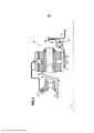
[0018] Outras características e vantagens da presente invenção são mais bem divulgadas a partir da descrição seguinte realizada com referência aos desenhos anexos, que mostram uma modalidade que não tem caráter limitador e em que: - A Figura 1 é uma vista de meio corte longitudinal diagramático de um turbopropulsor de dois propulsores que tem um dispositivo de engrenagem epicíclico de acordo com a invenção; - A Figura 2 é uma vista detalhada que mostra o dispositivo de engrenagem epicíclico da invenção; e - A Figura 3 é uma vista que mostra uma segunda modalidade de um dispositivo de engrenagem epicíclico da invenção aplicada a um turborreator com uma caixa de engrenagens e um único propulsor.[0018] Other features and advantages of the present invention are better disclosed from the following description carried out with reference to the attached drawings, which show an embodiment that has no limiting character and in which: - Figure 1 is a half-longitudinal section view diagrammatic of a two-propeller turboprop having an epicyclic gear device in accordance with the invention; - Figure 2 is a detailed view showing the epicyclic gear device of the invention; and - Figure 3 is a view showing a second embodiment of an epicyclic gear device of the invention applied to a turbojet with a gearbox and a single impeller.
[0019] A Figura 1 é uma vista altamente diagramática de uma modalidade de um turbopropulsor de aeronave do tipo que tem dois propulsores (impulsionador de rotor aberto), em que o dispositivo de engrenagem epicíclico da invenção pode ser incorporado. Esse turbopropulsor é bem conhecido e, portanto, não é descrito em detalhes.[0019] Figure 1 is a highly diagrammatic view of an embodiment of an aircraft turboprop of the type having two thrusters (open rotor thruster), in which the epicyclic gear device of the invention may be incorporated. This turboprop is well known and therefore not described in detail.
[0020] O turbopropulsor 10 compreende, em particular, um eixo geométrico longitudinal 12 e uma nacela anular 14 disposta coaxialmente ao redor do eixo geométrico longitudinal. De uma posição a montante para a jusante, o turbopropulsor 10 compreende adicionalmente um compressor de baixa pressão 16, um compressor de alta pressão 18, uma câmara de combustão 20, uma turbina de baixa pressão 22 e uma turbina de pressão intermediária 24.[0020] The
[0021] A jusante da turbina de pressão intermediária 24 há um sistema de propulsores de contrarrotação, a saber, um primeiro conjunto (a montante ou frontal) 25a e um segundo conjunto (a jusante ou traseiro) 25b de pás de passo ajustável acionados em rotação por meio de uma turbina de baixa pressão 26 disposta a jusante da turbina de pressão intermediária 24. A turbina de baixa pressão compreende, em particular, um rotor 28 que aciona os dois conjuntos de pás 25a e 25b em rotação através de um dispositivo de engrenagem epicíclico 30.[0021] Downstream of the
[0022] Na invenção, o dispositivo de engrenagem epicíclico 30 compreende uma roda solar 32 sob a forma de uma roda com dentes externos, centralizada no eixo geométrico longitudinal 12 do turbopropulsor e presa, a montante, ao rotor 28 da turbina de baixa pressão 26. O mesmo apresenta, ainda, pelo menos um satélite 34 e, preferencialmente, uma pluralidade (na faixa de três a seis), em que cada satélite tem a forma de uma roda com dentes externos e intercalado com a roda solar 32.[0022] In the invention, the epicyclic gear device 30 comprises a
[0023] Cada satélite 34 apresenta um eixo geométrico que é fora do centro em relação ao eixo geométrico longitudinal 12 e é transportado de modo giratório através de um porta-satélite 36 centralizado no eixo geométrico longitudinal 12, em que o porta-satélite é preso, a jusante, ao conjunto de pás a montante 25a, de modo que possa acionar o mesmo diretamente em rotação ao redor do eixo geométrico longitudinal 12. O dispositivo de engrenagem epicíclico 30 também tem um anel 38 centralizado no eixo geométrico longitudinal 12 e é engrenado com cada um dos satélites 34 através de dentes internos, em que o anel é preso a jusante do conjunto de pás 25b a jusante para que se possa acionar o mesmo diretamente em rotação ao redor do eixo geométrico longitudinal 12.[0023] Each satellite 34 has an axis that is off-center with respect to the longitudinal axis 12 and is rotatably transported through a
[0024] Diz-se que essa engrenagem epicíclica é "invertida", visto que o eixo de acionamento 40 do propulsor a jusante na saída do anel está no interior do eixo de acionamento 42 do propulsor a montante na saída do porta-satélite. A vantagem dessa inversão é obter um torque no propulsor a jusante que seja menor do que o torque no propulsor a montante de modo a reduzir o tamanho do cubo do propulsor a jusante e, assim, seu peso. Com essa configuração, o propulsor a montante gira na direção oposta à turbina e o propulsor a jusante na mesma direção que a ventoinha. É naturalmente possível obter um trem de engrenagens direto, em que a configuração, isto é, direta ou invertida, é uma função do torque que é desejável ter disponível para cada elemento e é abrangida pela competência do elemento versado na técnica e, por sua vez, tem uma influência sobre uma seleção entre eixos que são flexíveis ou rígidos.[0024] This epicyclic gear is said to be "inverted", since the
[0025] Dessa forma, o rotor 28 da turbina de baixa pressão aciona a rotação da roda solar 32 do dispositivo de engrenagem epicíclico que, por sua vez, retransmite esse movimento de rotação, através do porta-satélite 36, (através dos satélites 34) e através do anel 38, tanto para o conjunto de pás a montante 25a quanto para o conjunto de pás a jusante 25b a fim de acionar os mesmos em rotação de uma maneira de contrarrotação.[0025] In this way, the
[0026] Conforme mostrado em maiores detalhes na Figura 2, a roda solar 32 é conectada ao rotor de uma maneira flexível (flexível na dobra) através de uma primeira junta de transmissão de esfera 44 e o anel 38 é conectado ao segundo propulsor (o segundo conjunto de pás ou a jusante 25b) de modo semelhante de maneira flexível através de uma segunda junta de transmissão de esfera 46, em que o porta-satélite 26 é conectado de uma maneira rígida ao primeiro propulsor (o primeiro conjunto de pás a montante 25a).[0026] As shown in greater detail in Figure 2, the
[0027] Mais precisamente, a primeira junta de transmissão de esfera 44 tem uma primeira extremidade, remota em relação a uma segunda extremidade constituída por uma porção anular 44a montada por um sistema de estrias 48 na roda solar 32, um flange 50 que se estende radialmente para dentro e fixado a um flange radial de um eixo de acionamento flexível 28a preso ao rotor 28 da turbina de baixa pressão através de uma pluralidade de conexões aparafusadas 52. A segunda junta de esfera de transmissão 46 tem sua primeira extremidade fixada ao anel 38 através de uma pluralidade de conexões aparafusadas 54 e sua segunda extremidade é fixada, de modo semelhante, através de uma pluralidade de conexões aparafusadas 56, ao eixo de acionamento flexível 40 preso ao segundo conjunto de pás 25b. De modo semelhante, uma pluralidade de conexões aparafusadas 58 fornece fixação entre o porta-satélite 36 e o eixo de acionamento rígido 42 preso ao primeiro conjunto de pás 25a.[0027] More precisely, the first ball transmission joint 44 has a first end remote from a second end constituted by an
[0028] Dessa forma, acoplando-se a roda solar e o anel a seus respectivos eixos através de juntas de transmissão de esfera de velocidade constante que serve para limitar as concentrações de estresse nos dentes dos elementos de rolamento no evento de desalinhamento angular ou radial, a necessidade de um grau axial de liberdade nos dentes (liberdade para se deslocar axialmente) é eliminada, embora seja essencial em trens de engrenagem epicíclica de dente reto da técnica anterior. Deve ser observado, ainda, que os eixos flexíveis e as duas juntas de transmissão de esfera fornecem um grau de adaptabilidade.[0028] In this way, coupling the sun wheel and the ring to their respective axes through constant speed ball transmission joints that serve to limit stress concentrations on the teeth of the bearing elements in the event of angular or radial misalignment , the need for an axial degree of freedom in the teeth (freedom to move axially) is eliminated, although it is essential in prior art spur epicyclic gear trains. It should also be noted that the flexible shafts and the two ball transmission joints provide a degree of adaptability.
[0029] Através do uso dessas juntas de velocidade constante, é possível eliminar um grau de liberdade para se mover em translação e, assim, para ter o regresso para os dentes que são helicoidais em vez de dentes que são retos e, devido à continuidade nas transmissões de força, a densidade de potência do dispositivo de engrenagem epicíclico é aumentada. Na prática, o trem de engrenagens epicíclico é um trem de engrenagens epicíclico duplo com rodas helicoidais montadas em oposição (hélice dupla). Dessa maneira, o movimento axial entre os elementos de rolamento do dispositivo de engrenagem é eliminado.[0029] Through the use of these constant velocity joints, it is possible to eliminate a degree of freedom to move in translation and thus to have regress to teeth that are helical instead of teeth that are straight and due to continuity in power transmissions, the power density of the epicyclic gear device is increased. In practice, the epicyclic gear train is a double epicyclic gear train with oppositely mounted helical wheels (double helix). In this way, axial movement between the rolling elements of the gear device is eliminated.
[0030] As juntas de transmissão de esfera de velocidade constante são preferencialmente juntas Rzeppa que são montadas aos elementos de rolamento (roda solar ou anel) como uma função das opções disponíveis para incorporar as mesmas à turbomáquina. Os elementos da junta de transmissão de esfera (centros 44a, 46a; cubas 44b, 46b; gaiolas 44c, 46c; e esferas 44d, 46d) podem ser integrados diretamente aos elementos de rolamento e com os eixos, ou podem ser instalados separadamente, com a ajuda das estrias 48 para a roda solar 32 ou o flange aparafusado 54 para o anel 38, conforme mostrado na Figura 2.[0030] Constant speed ball transmission joints are preferably Rzeppa joints which are mounted to the rolling elements (solar wheel or ring) as a function of the options available to incorporate them into the turbomachine. Ball transmission joint elements (
[0031] Para aplicações de baixa potência (não mostradas), também é possível contemplar travar os elementos da junta de transmissão através de um grampo de mola e passa o acionamento meramente através de um acionamento, com contato entre as pistas e os elementos de rolamento que possivelmente também são mantidos meramente através de uma mola.[0031] For low power applications (not shown), it is also possible to contemplate locking the transmission joint elements through a spring clamp and passing the drive merely through a drive, with contact between the races and the rolling elements which are possibly also held merely by a spring.
[0032] Deve ser observado que tais juntas de transmissão de esfera de velocidade constante são sensíveis a movimentos axiais relativos entre esses vários componentes. Especificamente, um movimento axial do centro em relação à cuba pode ter o efeito de o contato ser perdido entre as esferas das juntas e suas superfícies de mancal. Portanto, é necessário saber os deslocamentos axiais possíveis que podem ocorrer entre os eixos durante a operação e pré-estressar as juntas de modo a conservar o contato entre as pistas das esferas em todas as circunstâncias de carregamento que são encontradas. Deve ser observado que as esferas que são mantidas em um plano comum através de uma gaiola, que é necessária para impedir que as esferas escapem durante o espaçamento axial relativo entre os dois elementos acoplados, em conjuntos, através das juntas, não podem pressionar as pistas, portanto, a compressão sobre a junta de transmissão não gera nenhum problema particular.[0032] It should be noted that such constant velocity ball transmission joints are sensitive to relative axial movements between these various components. Specifically, an axial movement of the center relative to the bowl can have the effect that contact is lost between the joint balls and their bearing surfaces. Therefore, it is necessary to know the possible axial displacements that can occur between the shafts during operation and to pre-stress the joints in order to maintain contact between the ball races under all the loading circumstances that are encountered. It should be noted that balls that are held in a common plane through a cage, which is necessary to prevent the balls from escaping during the relative axial spacing between the two elements coupled together, through the joints, cannot press on the raceways. , therefore, compression on the transmission joint does not create any particular problem.
[0033] Uma atenção mais particular deve ser fornecida ao posicionamento radial das duas juntas de transmissão 44 e 46 em relação aos mancais 60 e 62 que transportam os eixos de acionamento dos dois propulsores. Especificamente, quando o raciocínio em termos de desalinhamento que é puramente angular entre o eixo de acionamento rígido 42 (conectado ao porta-satélite) e um dentre os eixos de acionamento flexíveis 28a, 40 (conectados à roda solar e ao anel), é constatado se os centros de mancal das juntas de transmissão coincidem com o centro de rotação do eixo desalinhado, então, a rotação é livre e nenhum estresse de dobra é induzido nos eixos ou nos dentes dos elementos de rolamento. Visto que as posições desses centros são desconhecidas e variam como uma função das cargas aplicadas ao motor, é possível contemplar a aproximação de uma posição "média" de modo a maximizar a ação das juntas de transmissão e reduzir o estresse nos eixos de acionamento e nos dentes, ao passo que se usa as flexibilidades de dobra dos eixos de acionamento flexíveis do anel e da roda solar. Essas capacidades de adaptação tornam possível, em particular, admitir um desalinhamento radial potencial entre dois dos eixos de acionamento que devem admitir que uma porção dos estresses associada a esses eixos se dobre nos dentes. Especificamente, é constatado que durante o desalinhamento angular ou radial do eixo de turbina em relação ao eixo de acionamento rígido do primeiro propulsor, a configuração geométrica da junta de transmissão presa à roda solar exercerá uma influência sobre a distribuição de estresses.[0033] More particular attention must be paid to the radial positioning of the two
[0034] É vantajoso observar que na ocorrência de um desalinhamento radial entre o eixo de acionamento rígido do primeiro propulsor e um dos eixos flexíveis, o dispositivo irá tender a retornar a uma configuração em que ambos os eixos são desalinhados apenas angularmente, em que os únicos estresses que são inevitáveis nos dentes são os necessários para dobrar o eixo flexível a fim de retornar a essa configuração. É particularmente vantajoso assegurar que os eixos flexíveis sejam tão flexíveis quanto possível.[0034] It is advantageous to observe that in the event of a radial misalignment between the rigid drive shaft of the first impeller and one of the flexible shafts, the device will tend to return to a configuration in which both axes are only angularly misaligned, in which the the only stresses that are unavoidable on the teeth are those required to bend the flexible shaft in order to return to this configuration. It is particularly advantageous to ensure that flexible shafts are as flexible as possible.
[0035] Embora a descrição acima seja fornecida em relação às juntas Rzeppa, é naturalmente possível obter o regresso para outros tipos de juntas de transmissão de esfera de velocidade constante, como uma junta Weiss, uma junta de imersão ou, de fato, uma junta de imersão de deslocamento duplo.[0035] While the above description is given in relation to Rzeppa joints, it is naturally possible to get back to other types of constant velocity ball transmission joints such as a Weiss joint, a dip joint or indeed a joint double displacement immersion.
[0036] As juntas de imersão e juntas de imersão de deslocamento duplo são particularmente vantajosas, visto que têm pistas retas, que fornecem um grau adicional de liberdade (axialmente) e, assim, elimina a necessidade de adicionar pré- estresse para permitir que uma fração das forças de impulso passe através do trem de engrenagens epicíclico em vez de ser comunicada à estrutura através dos mancais dos eixos de acionamento conforme mencionado acima. Em comparação, o deslocamento angular aceitável é menor do que para uma junta Rzeppa, mas pode ser de até cerca de vinte graus, que é, de modo geral, totalmente suficiente.[0036] Plunge joints and double displacement plunge joints are particularly advantageous as they have straight raceways, which provide an additional degree of freedom (axially) and thus eliminate the need to add pre-stress to allow a fraction of the thrust forces pass through the epicyclic gear train rather than being communicated to the frame through the drive shaft bearings as mentioned above. In comparison, the acceptable angular displacement is less than for an Rzeppa joint, but can be up to about twenty degrees, which is generally quite sufficient.
[0037] Mais particularmente, para uma junta de imersão "VL", as pistas geradas por curvas cruzadas são linhas retas dispostas com as bordas de uma única folha hiperboloide, que é inclinada de modo alternado para a direita e para a esquerda, em que há seis acoplamentos. As mesmas são produzidas sob a forma de sulcos externos nos sulcos centrais e interno na cuba, que são colocados em correspondência pelas esferas. Devido à configuração cruzada das pistas, é essencial que a gaiola, que retém as esferas em conjunto, forneça liberdade em uma direção circunferencial a fim de possibilitar que as esferas sigam as pistas no caso de movimento axial relativo entre os dois elementos acoplados em conjunto.[0037] More particularly, for a "VL" plunge joint, the tracks generated by cross curves are straight lines arranged with the edges of a single hyperboloid sheet, which is angled alternately to the right and to the left, where there are six couplings. They are produced in the form of external grooves in the central and internal grooves in the vat, which are placed in correspondence by the spheres. Due to the cross configuration of the races, it is essential that the cage, which holds the balls together, provides freedom in a circumferential direction in order to enable the balls to follow the races in the event of relative axial movement between the two elements coupled together.
[0038] Dessa forma, a invenção torna possível reduzir o nível de estresse nos dentes através do fornecimento de uma arquitetura que absorve completamente o desalinhamento axial entre os eixos de acionamento e, assim, entre os elementos de componente do dispositivo de engrenagem epicíclico, sem gerar os estresses de sistemas da técnica anterior.[0038] In this way, the invention makes it possible to reduce the level of stress on the teeth by providing an architecture that completely absorbs the axial misalignment between the drive shafts and thus between the component elements of the epicyclic gear device, without generate the stresses of prior art systems.
[0039] Naturalmente, embora o dispositivo de engrenagem epicíclico da invenção seja descrito com referência ao turbopropulsor da Figura 1, deve ser observado que a mesma arquitetura é completamente aplicável a um turborreator de aeronave do tipo de duas ventoinhas (em que as pás a jusante agora são dispostas a montante). Nessa aplicação, a roda solar 32 centralizada no eixo geométrico longitudinal 12 do turborreator, então, é presa a jusante ao rotor 28 da turbina de baixa pressão 26. Cada um dos satélites 34 engrenados com a roda solar 32 apresenta um eixo geométrico que é fora de centro em relação ao eixo geométrico longitudinal 12 e os mesmos são transportados de modo giratório por um porta- satélite 36 que é centralizado no eixo geométrico longitudinal, em que o porta- satélite é preso a montante ao primeiro conjunto de pás 25a da ventoinha, de modo que possa acionar a mesma diretamente em rotação ao redor do eixo geométrico longitudinal 12. Por fim, o anel 38 centralizado no eixo geométrico longitudinal 12 e engrenado com cada satélite 34 é preso a montante ao segundo conjunto de pás 25b de modo que possa acionar a ventoinha diretamente em rotação ao redor do eixo geométrico longitudinal 12.[0039] Of course, although the epicyclic gear device of the invention is described with reference to the turboprop of Figure 1, it should be noted that the same architecture is fully applicable to a two-fan type aircraft turbojet (where the downstream blades are now arranged upstream). In that application, the
[0040] De modo semelhante, embora a invenção seja aplicada, nas duas modalidades acima, a engrenagens que atuam diferentemente em dois conjuntos de pás de contrarrotação, é claro que a mesma possa, igualmente, ser aplicada, conforme mostrado na Figura 3, a engrenagens que atuam em um único propulsor ou ventoinha em que um dos elementos do dispositivo de engrenagem é bloqueado (em que o problema de estresses nos dentes permanece o mesmo).[0040] Similarly, although the invention is applied, in the two embodiments above, to gears that act differently in two sets of counter-rotating blades, it is clear that the same can also be applied, as shown in Figure 3, the gears acting on a single impeller or fan where one of the elements of the gear device is blocked (where the problem of tooth stresses remains the same).
[0041] Especificamente, em uma turbomáquina com engrenagens (um turbopropulsor com um propulsor ou um turborreator com uma ventoinha), a engrenagem 70 é interposta entre o compressor de baixa pressão, que pode ser acionado a uma alta velocidade e a ventoinha, que, por outro lado, pode ser acionada a uma baixa velocidade. A engrenagem 70 convencionalmente tem um anel estacionário 72, uma roda solar 74 acionada pelo eixo de baixa pressão 76 do rotor do compressor de baixa pressão e satélites 78 que atuam através de seu porta- satélite 80 para acionar o eixo de ventoinha 82 da ventoinha.[0041] Specifically, in a geared turbomachine (a turboprop with an impeller or a turbojet with a fan), gear 70 is interposed between the low pressure compressor, which can be driven at a high speed, and the fan, which, on the other hand, it can be driven at low speed. Gear 70 conventionally has a stationary ring 72, a sun wheel 74 driven by the low pressure shaft 76 of the low pressure compressor rotor, and satellites 78 which act through its satellite carrier 80 to drive the
[0042] Diferente da modalidade descrita acima, o trem de engrenagens epicíclico usado é um trem de engrenagens convencional, não um trem de engrenagens diferencial, que tem uma entrada: o eixo de baixa pressão 76 e uma saída: o eixo de ventoinha 82. Na invenção, visto que o eixo de ventoinha é rígido, a adaptabilidade é obtida para o eixo de baixa pressão, que é conectado à roda solar através de uma junta de transmissão de esfera de velocidade constante 84.[0042] Unlike the embodiment described above, the epicyclic gear train used is a conventional gear train, not a differential gear train, which has an input: the low pressure shaft 76 and an output: the
[0043] Mais precisamente, essa junta de transmissão de esfera de velocidade constante 84 tem uma extremidade a montante remota em relação a uma extremidade a jusante constituída por uma porção anular 84a montada por um sistema de estrias 86 na roda solar 74 e um flange 88 que se estende radialmente para fora e fixo a uma placa radial do eixo de baixa pressão 76 através de uma pluralidade de conexões aparafusadas 90.[0043] More precisely, that constant velocity ball transmission joint 84 has an upstream end remote from a downstream end constituted by an annular portion 84a mounted by a spline system 86 on the sun wheel 74 and a
[0044] Quando a engrenagem tem mancais lisos, a junta de transmissão de esfera de velocidade constante é vantajosamente uma junta Rzeppa ou uma junta Weiss a fim de evitar apresentar qualquer grau axial de liberdade. A montagem resultante, portanto, é isostática.[0044] When the gear has plain bearings, the constant speed ball transmission joint is advantageously an Rzeppa joint or a Weiss joint in order to avoid having any axial degree of freedom. The resulting assembly is therefore isostatic.
[0045] Por outro lado, se a engrenagem tiver mancais de tambor, a junta de transmissão de esfera de velocidade constante é vantajosamente uma junta de imersão ou uma junta de imersão de deslocamento duplo, visto que, nesse caso, é necessário fornecer uma conexão estriada deslizante entre o anel e o invólucro (não mostrado) a fim de eliminar o grau adicional de liberdade conferido pela junta.[0045] On the other hand, if the gear has drum bearings, the constant speed ball transmission joint is advantageously a plunger joint or a double displacement plunger joint, since in that case it is necessary to provide a connection sliding groove between ring and housing (not shown) to eliminate the additional degree of freedom provided by the gasket.
Claims (10)
Applications Claiming Priority (3)
| Application Number | Priority Date | Filing Date | Title |
|---|---|---|---|
| FR1450080 | 2014-01-07 | ||
| FR1450080A FR3016189B1 (en) | 2014-01-07 | 2014-01-07 | EPICYCLOIDAL REDUCTION DEVICE FOR THE ROTATIONAL DRIVE OF BLADE ASSEMBLIES OF A REDUCING TURBOMACHINE |
| PCT/FR2014/053553 WO2015104474A1 (en) | 2014-01-07 | 2014-12-24 | Epicyclic reduction device for the rotational drive of blade sets of a reduction turbomachine |
Publications (2)
| Publication Number | Publication Date |
|---|---|
| BR112016015768A2 BR112016015768A2 (en) | 2017-08-08 |
| BR112016015768B1 true BR112016015768B1 (en) | 2022-05-10 |
Family
ID=50729601
Family Applications (1)
| Application Number | Title | Priority Date | Filing Date |
|---|---|---|---|
| BR112016015768-0A BR112016015768B1 (en) | 2014-01-07 | 2014-12-24 | EPIC-CYCLIC GEAR DEVICE FOR DRIVING THE ROTATION OF AT LEAST ONE FIRST SET OF BLADES OF A TURBOMACHINE |
Country Status (9)
| Country | Link |
|---|---|
| US (1) | US10495005B2 (en) |
| EP (1) | EP3092396B1 (en) |
| JP (1) | JP6526019B2 (en) |
| CN (1) | CN105899794B (en) |
| BR (1) | BR112016015768B1 (en) |
| CA (1) | CA2936046C (en) |
| FR (1) | FR3016189B1 (en) |
| RU (1) | RU2673639C2 (en) |
| WO (1) | WO2015104474A1 (en) |
Families Citing this family (11)
| Publication number | Priority date | Publication date | Assignee | Title |
|---|---|---|---|---|
| EP2904250A4 (en) * | 2012-10-01 | 2015-10-21 | United Technologies Corp | Geared turbofan high gearbox power density |
| FR3041990B1 (en) * | 2015-10-05 | 2019-03-22 | Safran Aircraft Engines | PROPELLER ASSEMBLY OF AN AIRCRAFT |
| US10801442B2 (en) * | 2017-02-08 | 2020-10-13 | General Electric Company | Counter rotating turbine with reversing reduction gear assembly |
| DE102017008674A1 (en) * | 2017-09-15 | 2019-03-21 | Rolls-Royce Deutschland Ltd & Co Kg | planetary gear |
| FR3072749B1 (en) * | 2017-10-24 | 2020-01-03 | Safran Transmission Systems | EPICYCLOIDAL GEAR TRAIN |
| FR3081959B1 (en) * | 2018-06-05 | 2020-07-17 | Safran Transmission Systems | METHOD FOR ASSEMBLING A REDUCER AND INSTALLATION FOR IMPLEMENTING THE METHOD |
| EP3587773B1 (en) * | 2018-06-27 | 2022-06-08 | Rolls-Royce plc | Gas turbine |
| US11174916B2 (en) | 2019-03-21 | 2021-11-16 | Pratt & Whitney Canada Corp. | Aircraft engine reduction gearbox |
| US11268453B1 (en) | 2021-03-17 | 2022-03-08 | Pratt & Whitney Canada Corp. | Lubrication system for aircraft engine reduction gearbox |
| FR3125018A1 (en) * | 2021-07-06 | 2023-01-13 | Safran Aircraft Engines | Boundary layer ingestion aircraft propulsion system |
| US11852080B1 (en) * | 2022-08-05 | 2023-12-26 | General Electric Company | Gearbox assembly |
Family Cites Families (23)
| Publication number | Priority date | Publication date | Assignee | Title |
|---|---|---|---|---|
| GB817490A (en) * | 1956-05-04 | 1959-07-29 | W H Allen Sons & Company Ltd | Improvements in and relating to flexible couplings for transmitting or restraining torque especially in planetary or epicyclic gearing |
| US3352178A (en) * | 1965-11-15 | 1967-11-14 | Gen Motors Corp | Planetary gearing |
| US5116293A (en) * | 1990-02-14 | 1992-05-26 | Dana Corporation | Four wheel drive transfer case with cv joint angled front output shaft |
| RU2056002C1 (en) * | 1991-01-08 | 1996-03-10 | Григорий Павлович Павлов | Planetary mechanism |
| JP3465120B2 (en) | 1994-08-23 | 2003-11-10 | 日本車輌製造株式会社 | Power transmission device using planetary roller transmission |
| JPH11190397A (en) * | 1997-12-26 | 1999-07-13 | Nissan Motor Co Ltd | Rolling vibration reducing device for engine |
| DE19828562B4 (en) * | 1998-06-26 | 2005-09-08 | Mtu Aero Engines Gmbh | Engine with counter-rotating rotors |
| FR2817912B1 (en) * | 2000-12-07 | 2003-01-17 | Hispano Suiza Sa | REDUCER TAKING OVER THE AXIAL EFFORTS GENERATED BY THE BLOWER OF A TURBO-JET |
| US6666102B2 (en) * | 2002-05-16 | 2003-12-23 | Sikorsky Aircraft Corporation | Flexible bearing arrangement for double helical pinion |
| FR2866068B1 (en) * | 2004-02-06 | 2006-07-07 | Snecma Moteurs | SOLIDARITY BLOWER TURBOREACTOR OF A DRIVE SHAFT SUPPORTED BY A FIRST AND A SECOND BEARING |
| US7726113B2 (en) * | 2005-10-19 | 2010-06-01 | General Electric Company | Gas turbine engine assembly and methods of assembling same |
| US7591754B2 (en) * | 2006-03-22 | 2009-09-22 | United Technologies Corporation | Epicyclic gear train integral sun gear coupling design |
| BE1017140A3 (en) * | 2006-05-15 | 2008-03-04 | Hansen Transmissions Int | PRESSER COMB FOR A GEAR GEAR TRANSMISSION. |
| US7694505B2 (en) * | 2006-07-31 | 2010-04-13 | General Electric Company | Gas turbine engine assembly and method of assembling same |
| US8753243B2 (en) * | 2006-08-15 | 2014-06-17 | United Technologies Corporation | Ring gear mounting arrangement with oil scavenge scheme |
| US20090062058A1 (en) * | 2007-08-27 | 2009-03-05 | Kimes John W | Plantary Transmission Having Double Helical Teeth |
| US8205432B2 (en) * | 2007-10-03 | 2012-06-26 | United Technologies Corporation | Epicyclic gear train for turbo fan engine |
| FR2940247B1 (en) * | 2008-12-19 | 2011-01-21 | Snecma | SYSTEM OF CONTRAROTATIVE PROPELLERS DRAWN BY AN EPICYCLOIDAL TRAIN PROVIDING A BALANCED TORQUE DISTRIBUTION BETWEEN THE TWO PROPELLERS |
| FR2942284B1 (en) * | 2009-02-16 | 2011-03-04 | Snecma | LUBRICATION AND COOLING OF AN EPICYCLOIDAL GEAR TRAIN REDUCER |
| FR2943035B1 (en) * | 2009-03-11 | 2012-09-28 | Snecma | DEVICE FOR DRIVING A PAIRE OF CONTRAROTIVE PROPELLERS BY AN EPYCYCLOIDAL TRAIN |
| US20110143880A1 (en) * | 2010-12-01 | 2011-06-16 | General Electric Company | Drivetrain for generator in wind turbine |
| FR2979121B1 (en) * | 2011-08-18 | 2013-09-06 | Snecma | MECHANICAL TRANSMISSION DEVICE FOR THE ROTATION DRIVE OF THE CONTRAROTATIVE PROPELLERS OF A DOUBLE PROPELLER TURBOPROPULSOR. |
| US8720306B2 (en) * | 2012-01-31 | 2014-05-13 | United Technologies Corporation | Turbine engine gearbox |
-
2014
- 2014-01-07 FR FR1450080A patent/FR3016189B1/en not_active Expired - Fee Related
- 2014-12-24 JP JP2016545300A patent/JP6526019B2/en active Active
- 2014-12-24 WO PCT/FR2014/053553 patent/WO2015104474A1/en active Application Filing
- 2014-12-24 CA CA2936046A patent/CA2936046C/en active Active
- 2014-12-24 EP EP14831030.3A patent/EP3092396B1/en active Active
- 2014-12-24 BR BR112016015768-0A patent/BR112016015768B1/en active IP Right Grant
- 2014-12-24 CN CN201480072535.8A patent/CN105899794B/en active Active
- 2014-12-24 RU RU2016132494A patent/RU2673639C2/en active
- 2014-12-24 US US15/110,001 patent/US10495005B2/en active Active
Also Published As
| Publication number | Publication date |
|---|---|
| CA2936046A1 (en) | 2015-07-16 |
| US10495005B2 (en) | 2019-12-03 |
| US20160326964A1 (en) | 2016-11-10 |
| RU2016132494A (en) | 2018-02-16 |
| RU2673639C2 (en) | 2018-11-28 |
| FR3016189A1 (en) | 2015-07-10 |
| RU2016132494A3 (en) | 2018-09-28 |
| JP6526019B2 (en) | 2019-06-05 |
| BR112016015768A2 (en) | 2017-08-08 |
| CN105899794B (en) | 2018-03-13 |
| CN105899794A (en) | 2016-08-24 |
| FR3016189B1 (en) | 2018-09-28 |
| WO2015104474A1 (en) | 2015-07-16 |
| CA2936046C (en) | 2022-04-12 |
| EP3092396A1 (en) | 2016-11-16 |
| JP2017503960A (en) | 2017-02-02 |
| EP3092396B1 (en) | 2019-09-18 |
Similar Documents
| Publication | Publication Date | Title |
|---|---|---|
| BR112016015768B1 (en) | EPIC-CYCLIC GEAR DEVICE FOR DRIVING THE ROTATION OF AT LEAST ONE FIRST SET OF BLADES OF A TURBOMACHINE | |
| US3922852A (en) | Variable pitch fan for gas turbine engine | |
| RU2359875C1 (en) | Reduction gear with separation of torque for rotary-wing aircraft with system of forward traction | |
| US8899926B2 (en) | Counter rotating facegear gearbox | |
| JP6313852B2 (en) | Oil feeding device between two oil containers rotating relative to each other and aircraft propeller turbomachine equipped with the device | |
| WO2009144164A1 (en) | Turbo-machine having at least two counter-rotatable rotors and having mechanical torque compensation | |
| US3902822A (en) | Modular gearbox for a variable pitch fan propulsor | |
| US10012176B2 (en) | Aircraft gas turbine comprising a thrust-reverser device with cascade elements and an integrated rack and pinion drive | |
| US3536415A (en) | Cyclic pitch actuator | |
| WO2016139641A1 (en) | Aircraft capable of hovering | |
| US9416733B2 (en) | Sealing device having a sleeve for the passage of a connecting rod of a system for controlling the orientation of the blower blades of a turboprop engine through a partition | |
| GB1559879A (en) | Bevel gearing | |
| CN113167373B (en) | Aircraft with hover capability | |
| US10358211B2 (en) | Rotor apparatus | |
| US10494089B2 (en) | Drive shaft system hanger bearing | |
| US1990606A (en) | Shafting for power transmission | |
| US2423820A (en) | Transmission gearing for power plants | |
| US3564937A (en) | Mechanical drive with angle power transmission | |
| US3472321A (en) | Fan | |
| US10364038B2 (en) | Propulsion unit for an aircraft | |
| US3309936A (en) | Reduction gear construction | |
| US10093413B2 (en) | Drive system for aircraft landing gear | |
| US2739490A (en) | Transmission mechanism, including bevel pinions | |
| RU119414U1 (en) | TWO-STAGE CENTRIFUGAL COMPRESSOR | |
| US1912955A (en) | Drive transmission gear of the bevel differential type |
Legal Events
| Date | Code | Title | Description |
|---|---|---|---|
| B06U | Preliminary requirement: requests with searches performed by other patent offices: procedure suspended [chapter 6.21 patent gazette] | ||
| B09A | Decision: intention to grant [chapter 9.1 patent gazette] | ||
| B16A | Patent or certificate of addition of invention granted [chapter 16.1 patent gazette] |
Free format text: PRAZO DE VALIDADE: 20 (VINTE) ANOS CONTADOS A PARTIR DE 24/12/2014, OBSERVADAS AS CONDICOES LEGAIS |