BR112016013450B1 - CURABLE COMPOSITE MATERIAL, AND, METHODS FOR MAKING A CURABLE COMPOSITE MATERIAL AND FOR MAKING A COMPOSITE STRUCTURE - Google Patents
CURABLE COMPOSITE MATERIAL, AND, METHODS FOR MAKING A CURABLE COMPOSITE MATERIAL AND FOR MAKING A COMPOSITE STRUCTURE Download PDFInfo
- Publication number
- BR112016013450B1 BR112016013450B1 BR112016013450-8A BR112016013450A BR112016013450B1 BR 112016013450 B1 BR112016013450 B1 BR 112016013450B1 BR 112016013450 A BR112016013450 A BR 112016013450A BR 112016013450 B1 BR112016013450 B1 BR 112016013450B1
- Authority
- BR
- Brazil
- Prior art keywords
- particles
- curable
- carbon
- composite material
- matrix resin
- Prior art date
Links
- 239000002131 composite material Substances 0.000 title claims abstract description 138
- 238000000034 method Methods 0.000 title claims abstract description 28
- 239000002245 particle Substances 0.000 claims abstract description 260
- 229920005989 resin Polymers 0.000 claims abstract description 171
- 239000011347 resin Substances 0.000 claims abstract description 171
- 239000011159 matrix material Substances 0.000 claims abstract description 92
- OKTJSMMVPCPJKN-UHFFFAOYSA-N Carbon Chemical compound [C] OKTJSMMVPCPJKN-UHFFFAOYSA-N 0.000 claims abstract description 83
- 229910052799 carbon Inorganic materials 0.000 claims abstract description 63
- 239000012783 reinforcing fiber Substances 0.000 claims abstract description 31
- 229920000642 polymer Polymers 0.000 claims abstract description 26
- -1 e.g. Substances 0.000 claims abstract description 20
- 239000002041 carbon nanotube Substances 0.000 claims abstract description 18
- 229910021393 carbon nanotube Inorganic materials 0.000 claims abstract description 15
- 229920001169 thermoplastic Polymers 0.000 claims description 48
- 239000010410 layer Substances 0.000 claims description 47
- 239000004416 thermosoftening plastic Substances 0.000 claims description 29
- 239000000463 material Substances 0.000 claims description 16
- 238000003475 lamination Methods 0.000 claims description 15
- 229920001187 thermosetting polymer Polymers 0.000 claims description 15
- 238000004132 cross linking Methods 0.000 claims description 14
- 239000003431 cross linking reagent Substances 0.000 claims description 10
- 239000004642 Polyimide Substances 0.000 claims description 9
- 239000004954 Polyphthalamide Substances 0.000 claims description 9
- 229920001721 polyimide Polymers 0.000 claims description 9
- 229920006375 polyphtalamide Polymers 0.000 claims description 9
- 229920001643 poly(ether ketone) Polymers 0.000 claims description 8
- 239000004952 Polyamide Substances 0.000 claims description 7
- 229920001577 copolymer Polymers 0.000 claims description 7
- VNWKTOKETHGBQD-UHFFFAOYSA-N methane Chemical class C VNWKTOKETHGBQD-UHFFFAOYSA-N 0.000 claims description 7
- 229920002647 polyamide Polymers 0.000 claims description 7
- 229920006260 polyaryletherketone Polymers 0.000 claims description 5
- 239000004734 Polyphenylene sulfide Substances 0.000 claims description 4
- 150000001875 compounds Chemical class 0.000 claims description 4
- 229920000069 polyphenylene sulfide Polymers 0.000 claims description 4
- 239000004962 Polyamide-imide Substances 0.000 claims description 3
- 239000004793 Polystyrene Substances 0.000 claims description 3
- 229910002804 graphite Inorganic materials 0.000 claims description 3
- 239000010439 graphite Substances 0.000 claims description 3
- 238000010030 laminating Methods 0.000 claims description 3
- 229920002312 polyamide-imide Polymers 0.000 claims description 3
- 229920002857 polybutadiene Polymers 0.000 claims description 3
- 229920002223 polystyrene Polymers 0.000 claims description 3
- 239000002356 single layer Substances 0.000 claims description 3
- 229920000106 Liquid crystal polymer Polymers 0.000 claims description 2
- 239000004977 Liquid-crystal polymers (LCPs) Substances 0.000 claims description 2
- 239000005062 Polybutadiene Substances 0.000 claims description 2
- 239000006229 carbon black Substances 0.000 claims description 2
- 239000002134 carbon nanofiber Substances 0.000 claims description 2
- 229910021389 graphene Inorganic materials 0.000 claims description 2
- 239000002110 nanocone Substances 0.000 claims description 2
- 239000002135 nanosheet Substances 0.000 claims description 2
- 229920002239 polyacrylonitrile Polymers 0.000 claims description 2
- 239000002064 nanoplatelet Substances 0.000 claims 1
- 239000002086 nanomaterial Substances 0.000 abstract description 31
- 239000000835 fiber Substances 0.000 description 54
- 239000002048 multi walled nanotube Substances 0.000 description 32
- 239000011342 resin composition Substances 0.000 description 19
- 239000000203 mixture Substances 0.000 description 17
- RTZKZFJDLAIYFH-UHFFFAOYSA-N Diethyl ether Chemical compound CCOCC RTZKZFJDLAIYFH-UHFFFAOYSA-N 0.000 description 16
- 238000012360 testing method Methods 0.000 description 16
- 239000003795 chemical substances by application Substances 0.000 description 11
- 238000004519 manufacturing process Methods 0.000 description 10
- 230000006872 improvement Effects 0.000 description 9
- 239000000523 sample Substances 0.000 description 9
- 229920000049 Carbon (fiber) Polymers 0.000 description 8
- 239000004593 Epoxy Substances 0.000 description 8
- PXKLMJQFEQBVLD-UHFFFAOYSA-N bisphenol F Chemical compound C1=CC(O)=CC=C1CC1=CC=C(O)C=C1 PXKLMJQFEQBVLD-UHFFFAOYSA-N 0.000 description 8
- 239000004917 carbon fiber Substances 0.000 description 8
- 239000003822 epoxy resin Substances 0.000 description 8
- 230000001976 improved effect Effects 0.000 description 8
- 238000000386 microscopy Methods 0.000 description 8
- 229920000647 polyepoxide Polymers 0.000 description 8
- 230000000694 effects Effects 0.000 description 7
- 239000012798 spherical particle Substances 0.000 description 7
- PLIKAWJENQZMHA-UHFFFAOYSA-N 4-aminophenol Chemical compound NC1=CC=C(O)C=C1 PLIKAWJENQZMHA-UHFFFAOYSA-N 0.000 description 6
- 239000004695 Polyether sulfone Substances 0.000 description 6
- 239000004721 Polyphenylene oxide Substances 0.000 description 6
- 239000003054 catalyst Substances 0.000 description 6
- 238000009472 formulation Methods 0.000 description 6
- 229920003986 novolac Polymers 0.000 description 6
- 229920006393 polyether sulfone Polymers 0.000 description 6
- 229920005649 polyetherethersulfone Polymers 0.000 description 6
- 229920003319 Araldite® Polymers 0.000 description 5
- 239000004696 Poly ether ether ketone Substances 0.000 description 5
- 238000004458 analytical method Methods 0.000 description 5
- 125000003118 aryl group Chemical group 0.000 description 5
- IISBACLAFKSPIT-UHFFFAOYSA-N bisphenol A Chemical compound C=1C=C(O)C=CC=1C(C)(C)C1=CC=C(O)C=C1 IISBACLAFKSPIT-UHFFFAOYSA-N 0.000 description 5
- 239000011248 coating agent Substances 0.000 description 5
- 238000000576 coating method Methods 0.000 description 5
- 230000032798 delamination Effects 0.000 description 5
- 238000010438 heat treatment Methods 0.000 description 5
- 238000005259 measurement Methods 0.000 description 5
- ISWSIDIOOBJBQZ-UHFFFAOYSA-N phenol group Chemical group C1(=CC=CC=C1)O ISWSIDIOOBJBQZ-UHFFFAOYSA-N 0.000 description 5
- 229920001652 poly(etherketoneketone) Polymers 0.000 description 5
- 229920002530 polyetherether ketone Polymers 0.000 description 5
- 229920006380 polyphenylene oxide Polymers 0.000 description 5
- 230000008569 process Effects 0.000 description 5
- 230000009467 reduction Effects 0.000 description 5
- YBRVSVVVWCFQMG-UHFFFAOYSA-N 4,4'-diaminodiphenylmethane Chemical compound C1=CC(N)=CC=C1CC1=CC=C(N)C=C1 YBRVSVVVWCFQMG-UHFFFAOYSA-N 0.000 description 4
- 229920002430 Fibre-reinforced plastic Polymers 0.000 description 4
- 229920003235 aromatic polyamide Polymers 0.000 description 4
- 238000006243 chemical reaction Methods 0.000 description 4
- 239000000470 constituent Substances 0.000 description 4
- 230000007423 decrease Effects 0.000 description 4
- 229920001971 elastomer Polymers 0.000 description 4
- 150000002170 ethers Chemical class 0.000 description 4
- 239000011151 fibre-reinforced plastic Substances 0.000 description 4
- LNEPOXFFQSENCJ-UHFFFAOYSA-N haloperidol Chemical compound C1CC(O)(C=2C=CC(Cl)=CC=2)CCN1CCCC(=O)C1=CC=C(F)C=C1 LNEPOXFFQSENCJ-UHFFFAOYSA-N 0.000 description 4
- 238000001000 micrograph Methods 0.000 description 4
- 230000002195 synergetic effect Effects 0.000 description 4
- WSFSSNUMVMOOMR-UHFFFAOYSA-N Formaldehyde Chemical compound O=C WSFSSNUMVMOOMR-UHFFFAOYSA-N 0.000 description 3
- KWYHDKDOAIKMQN-UHFFFAOYSA-N N,N,N',N'-tetramethylethylenediamine Chemical compound CN(C)CCN(C)C KWYHDKDOAIKMQN-UHFFFAOYSA-N 0.000 description 3
- 239000002253 acid Substances 0.000 description 3
- 239000000654 additive Substances 0.000 description 3
- 150000001412 amines Chemical class 0.000 description 3
- 150000008064 anhydrides Chemical class 0.000 description 3
- 238000013459 approach Methods 0.000 description 3
- 239000004760 aramid Substances 0.000 description 3
- 239000002717 carbon nanostructure Substances 0.000 description 3
- 230000008859 change Effects 0.000 description 3
- 238000001816 cooling Methods 0.000 description 3
- GYZLOYUZLJXAJU-UHFFFAOYSA-N diglycidyl ether Chemical compound C1OC1COCC1CO1 GYZLOYUZLJXAJU-UHFFFAOYSA-N 0.000 description 3
- 239000000839 emulsion Substances 0.000 description 3
- 239000000446 fuel Substances 0.000 description 3
- 239000002828 fuel tank Substances 0.000 description 3
- 230000009477 glass transition Effects 0.000 description 3
- 229920001519 homopolymer Polymers 0.000 description 3
- 229920001601 polyetherimide Polymers 0.000 description 3
- 230000002787 reinforcement Effects 0.000 description 3
- 230000035882 stress Effects 0.000 description 3
- 229920001567 vinyl ester resin Polymers 0.000 description 3
- KUBDPQJOLOUJRM-UHFFFAOYSA-N 2-(chloromethyl)oxirane;4-[2-(4-hydroxyphenyl)propan-2-yl]phenol Chemical compound ClCC1CO1.C=1C=C(O)C=CC=1C(C)(C)C1=CC=C(O)C=C1 KUBDPQJOLOUJRM-UHFFFAOYSA-N 0.000 description 2
- XMTQQYYKAHVGBJ-UHFFFAOYSA-N 3-(3,4-DICHLOROPHENYL)-1,1-DIMETHYLUREA Chemical compound CN(C)C(=O)NC1=CC=C(Cl)C(Cl)=C1 XMTQQYYKAHVGBJ-UHFFFAOYSA-N 0.000 description 2
- CWLKGDAVCFYWJK-UHFFFAOYSA-N 3-aminophenol Chemical compound NC1=CC=CC(O)=C1 CWLKGDAVCFYWJK-UHFFFAOYSA-N 0.000 description 2
- VPWNQTHUCYMVMZ-UHFFFAOYSA-N 4,4'-sulfonyldiphenol Chemical class C1=CC(O)=CC=C1S(=O)(=O)C1=CC=C(O)C=C1 VPWNQTHUCYMVMZ-UHFFFAOYSA-N 0.000 description 2
- 229930185605 Bisphenol Natural products 0.000 description 2
- XMWRBQBLMFGWIX-UHFFFAOYSA-N C60 fullerene Chemical compound C12=C3C(C4=C56)=C7C8=C5C5=C9C%10=C6C6=C4C1=C1C4=C6C6=C%10C%10=C9C9=C%11C5=C8C5=C8C7=C3C3=C7C2=C1C1=C2C4=C6C4=C%10C6=C9C9=C%11C5=C5C8=C3C3=C7C1=C1C2=C4C6=C2C9=C5C3=C12 XMWRBQBLMFGWIX-UHFFFAOYSA-N 0.000 description 2
- MQJKPEGWNLWLTK-UHFFFAOYSA-N Dapsone Chemical compound C1=CC(N)=CC=C1S(=O)(=O)C1=CC=C(N)C=C1 MQJKPEGWNLWLTK-UHFFFAOYSA-N 0.000 description 2
- 229920003171 Poly (ethylene oxide) Polymers 0.000 description 2
- 229920012266 Poly(ether sulfone) PES Polymers 0.000 description 2
- 229920003231 aliphatic polyamide Polymers 0.000 description 2
- 125000003277 amino group Chemical group 0.000 description 2
- 150000004982 aromatic amines Chemical class 0.000 description 2
- 230000008901 benefit Effects 0.000 description 2
- GCAIEATUVJFSMC-UHFFFAOYSA-N benzene-1,2,3,4-tetracarboxylic acid Chemical compound OC(=O)C1=CC=C(C(O)=O)C(C(O)=O)=C1C(O)=O GCAIEATUVJFSMC-UHFFFAOYSA-N 0.000 description 2
- 230000015572 biosynthetic process Effects 0.000 description 2
- 230000000052 comparative effect Effects 0.000 description 2
- 238000007906 compression Methods 0.000 description 2
- 230000006835 compression Effects 0.000 description 2
- 238000010276 construction Methods 0.000 description 2
- 239000004643 cyanate ester Substances 0.000 description 2
- 238000013461 design Methods 0.000 description 2
- 238000009826 distribution Methods 0.000 description 2
- 239000002079 double walled nanotube Substances 0.000 description 2
- 238000001035 drying Methods 0.000 description 2
- 239000000806 elastomer Substances 0.000 description 2
- 229910003472 fullerene Inorganic materials 0.000 description 2
- 125000000524 functional group Chemical group 0.000 description 2
- 239000007789 gas Substances 0.000 description 2
- 230000004313 glare Effects 0.000 description 2
- 239000003365 glass fiber Substances 0.000 description 2
- 150000003949 imides Chemical class 0.000 description 2
- 238000001802 infusion Methods 0.000 description 2
- 239000012948 isocyanate Substances 0.000 description 2
- 238000011068 loading method Methods 0.000 description 2
- BMLIZLVNXIYGCK-UHFFFAOYSA-N monuron Chemical compound CN(C)C(=O)NC1=CC=C(Cl)C=C1 BMLIZLVNXIYGCK-UHFFFAOYSA-N 0.000 description 2
- 239000002071 nanotube Substances 0.000 description 2
- QWVGKYWNOKOFNN-UHFFFAOYSA-N o-cresol Chemical compound CC1=CC=CC=C1O QWVGKYWNOKOFNN-UHFFFAOYSA-N 0.000 description 2
- 229920001568 phenolic resin Polymers 0.000 description 2
- 229920002492 poly(sulfone) Polymers 0.000 description 2
- 229920000058 polyacrylate Polymers 0.000 description 2
- 229920000728 polyester Polymers 0.000 description 2
- 239000004848 polyfunctional curative Substances 0.000 description 2
- 230000008092 positive effect Effects 0.000 description 2
- 239000000565 sealant Substances 0.000 description 2
- 239000002109 single walled nanotube Substances 0.000 description 2
- 239000002904 solvent Substances 0.000 description 2
- 230000008961 swelling Effects 0.000 description 2
- 230000007704 transition Effects 0.000 description 2
- 125000000391 vinyl group Chemical group [H]C([*])=C([H])[H] 0.000 description 2
- XLYOFNOQVPJJNP-UHFFFAOYSA-N water Substances O XLYOFNOQVPJJNP-UHFFFAOYSA-N 0.000 description 2
- LTVUCOSIZFEASK-MPXCPUAZSA-N (3ar,4s,7r,7as)-3a-methyl-3a,4,7,7a-tetrahydro-4,7-methano-2-benzofuran-1,3-dione Chemical compound C([C@H]1C=C2)[C@H]2[C@H]2[C@]1(C)C(=O)OC2=O LTVUCOSIZFEASK-MPXCPUAZSA-N 0.000 description 1
- KNDQHSIWLOJIGP-UMRXKNAASA-N (3ar,4s,7r,7as)-rel-3a,4,7,7a-tetrahydro-4,7-methanoisobenzofuran-1,3-dione Chemical compound O=C1OC(=O)[C@@H]2[C@H]1[C@]1([H])C=C[C@@]2([H])C1 KNDQHSIWLOJIGP-UMRXKNAASA-N 0.000 description 1
- MUTGBJKUEZFXGO-OLQVQODUSA-N (3as,7ar)-3a,4,5,6,7,7a-hexahydro-2-benzofuran-1,3-dione Chemical compound C1CCC[C@@H]2C(=O)OC(=O)[C@@H]21 MUTGBJKUEZFXGO-OLQVQODUSA-N 0.000 description 1
- KMOUUZVZFBCRAM-OLQVQODUSA-N (3as,7ar)-3a,4,7,7a-tetrahydro-2-benzofuran-1,3-dione Chemical compound C1C=CC[C@@H]2C(=O)OC(=O)[C@@H]21 KMOUUZVZFBCRAM-OLQVQODUSA-N 0.000 description 1
- KGSFMPRFQVLGTJ-UHFFFAOYSA-N 1,1,2-triphenylethylbenzene Chemical compound C=1C=CC=CC=1C(C=1C=CC=CC=1)(C=1C=CC=CC=1)CC1=CC=CC=C1 KGSFMPRFQVLGTJ-UHFFFAOYSA-N 0.000 description 1
- PVXVWWANJIWJOO-UHFFFAOYSA-N 1-(1,3-benzodioxol-5-yl)-N-ethylpropan-2-amine Chemical compound CCNC(C)CC1=CC=C2OCOC2=C1 PVXVWWANJIWJOO-UHFFFAOYSA-N 0.000 description 1
- XQUPVDVFXZDTLT-UHFFFAOYSA-N 1-[4-[[4-(2,5-dioxopyrrol-1-yl)phenyl]methyl]phenyl]pyrrole-2,5-dione Chemical compound O=C1C=CC(=O)N1C(C=C1)=CC=C1CC1=CC=C(N2C(C=CC2=O)=O)C=C1 XQUPVDVFXZDTLT-UHFFFAOYSA-N 0.000 description 1
- HECLRDQVFMWTQS-RGOKHQFPSA-N 1755-01-7 Chemical compound C1[C@H]2[C@@H]3CC=C[C@@H]3[C@@H]1C=C2 HECLRDQVFMWTQS-RGOKHQFPSA-N 0.000 description 1
- KGRVJHAUYBGFFP-UHFFFAOYSA-N 2,2'-Methylenebis(4-methyl-6-tert-butylphenol) Chemical compound CC(C)(C)C1=CC(C)=CC(CC=2C(=C(C=C(C)C=2)C(C)(C)C)O)=C1O KGRVJHAUYBGFFP-UHFFFAOYSA-N 0.000 description 1
- VOZKAJLKRJDJLL-UHFFFAOYSA-N 2,4-diaminotoluene Chemical compound CC1=CC=C(N)C=C1N VOZKAJLKRJDJLL-UHFFFAOYSA-N 0.000 description 1
- CDAWCLOXVUBKRW-UHFFFAOYSA-N 2-aminophenol Chemical class NC1=CC=CC=C1O CDAWCLOXVUBKRW-UHFFFAOYSA-N 0.000 description 1
- UUODQIKUTGWMPT-UHFFFAOYSA-N 2-fluoro-5-(trifluoromethyl)pyridine Chemical compound FC1=CC=C(C(F)(F)F)C=N1 UUODQIKUTGWMPT-UHFFFAOYSA-N 0.000 description 1
- QTWJRLJHJPIABL-UHFFFAOYSA-N 2-methylphenol;3-methylphenol;4-methylphenol Chemical compound CC1=CC=C(O)C=C1.CC1=CC=CC(O)=C1.CC1=CC=CC=C1O QTWJRLJHJPIABL-UHFFFAOYSA-N 0.000 description 1
- RDIGYBZNNOGMHU-UHFFFAOYSA-N 3-amino-2,4,5-tris(oxiran-2-ylmethyl)phenol Chemical compound OC1=CC(CC2OC2)=C(CC2OC2)C(N)=C1CC1CO1 RDIGYBZNNOGMHU-UHFFFAOYSA-N 0.000 description 1
- 229940018563 3-aminophenol Drugs 0.000 description 1
- AQCLQMIIOAXRBP-UHFFFAOYSA-N 4-[2-(4-amino-3,5-dimethylphenyl)-3,6-di(propan-2-yl)phenyl]-2,6-dimethylaniline Chemical compound C=1C(C)=C(N)C(C)=CC=1C=1C(C(C)C)=CC=C(C(C)C)C=1C1=CC(C)=C(N)C(C)=C1 AQCLQMIIOAXRBP-UHFFFAOYSA-N 0.000 description 1
- RZVWLPZIPNEVCN-UHFFFAOYSA-N 4-[2-(4-aminophenyl)-3,6-di(propan-2-yl)phenyl]aniline Chemical compound C=1C=C(N)C=CC=1C=1C(C(C)C)=CC=C(C(C)C)C=1C1=CC=C(N)C=C1 RZVWLPZIPNEVCN-UHFFFAOYSA-N 0.000 description 1
- FAUAZXVRLVIARB-UHFFFAOYSA-N 4-[[4-[bis(oxiran-2-ylmethyl)amino]phenyl]methyl]-n,n-bis(oxiran-2-ylmethyl)aniline Chemical compound C1OC1CN(C=1C=CC(CC=2C=CC(=CC=2)N(CC2OC2)CC2OC2)=CC=1)CC1CO1 FAUAZXVRLVIARB-UHFFFAOYSA-N 0.000 description 1
- CXXSQMDHHYTRKY-UHFFFAOYSA-N 4-amino-2,3,5-tris(oxiran-2-ylmethyl)phenol Chemical compound C1=C(O)C(CC2OC2)=C(CC2OC2)C(N)=C1CC1CO1 CXXSQMDHHYTRKY-UHFFFAOYSA-N 0.000 description 1
- MWSKJDNQKGCKPA-UHFFFAOYSA-N 6-methyl-3a,4,5,7a-tetrahydro-2-benzofuran-1,3-dione Chemical compound C1CC(C)=CC2C(=O)OC(=O)C12 MWSKJDNQKGCKPA-UHFFFAOYSA-N 0.000 description 1
- KNDQHSIWLOJIGP-UHFFFAOYSA-N 826-62-0 Chemical compound C1C2C3C(=O)OC(=O)C3C1C=C2 KNDQHSIWLOJIGP-UHFFFAOYSA-N 0.000 description 1
- 239000004953 Aliphatic polyamide Substances 0.000 description 1
- ZOXJGFHDIHLPTG-UHFFFAOYSA-N Boron Chemical compound [B] ZOXJGFHDIHLPTG-UHFFFAOYSA-N 0.000 description 1
- PFPRBOBHHMQEFH-UHFFFAOYSA-N C=1CC(O)(O)C=CC=1C(C)(C)C1=CCC(O)(O)C=C1 Chemical compound C=1CC(O)(O)C=CC=1C(C)(C)C1=CCC(O)(O)C=C1 PFPRBOBHHMQEFH-UHFFFAOYSA-N 0.000 description 1
- 239000004215 Carbon black (E152) Substances 0.000 description 1
- 229920003270 Cymel® Polymers 0.000 description 1
- 239000005510 Diuron Substances 0.000 description 1
- 229920000271 Kevlar® Polymers 0.000 description 1
- 239000004997 Liquid crystal elastomers (LCEs) Substances 0.000 description 1
- QMMZSJPSPRTHGB-UHFFFAOYSA-N MDEA Natural products CC(C)CCCCC=CCC=CC(O)=O QMMZSJPSPRTHGB-UHFFFAOYSA-N 0.000 description 1
- PEEHTFAAVSWFBL-UHFFFAOYSA-N Maleimide Chemical compound O=C1NC(=O)C=C1 PEEHTFAAVSWFBL-UHFFFAOYSA-N 0.000 description 1
- 229920000877 Melamine resin Polymers 0.000 description 1
- XUMBMVFBXHLACL-UHFFFAOYSA-N Melanin Chemical class O=C1C(=O)C(C2=CNC3=C(C(C(=O)C4=C32)=O)C)=C2C4=CNC2=C1C XUMBMVFBXHLACL-UHFFFAOYSA-N 0.000 description 1
- 239000004677 Nylon Substances 0.000 description 1
- LGRFSURHDFAFJT-UHFFFAOYSA-N Phthalic anhydride Natural products C1=CC=C2C(=O)OC(=O)C2=C1 LGRFSURHDFAFJT-UHFFFAOYSA-N 0.000 description 1
- 239000004697 Polyetherimide Substances 0.000 description 1
- 229920000491 Polyphenylsulfone Polymers 0.000 description 1
- 239000004743 Polypropylene Substances 0.000 description 1
- 229920003295 Radel® Polymers 0.000 description 1
- BQCADISMDOOEFD-UHFFFAOYSA-N Silver Chemical compound [Ag] BQCADISMDOOEFD-UHFFFAOYSA-N 0.000 description 1
- 206010041316 Solvent sensitivity Diseases 0.000 description 1
- 239000002174 Styrene-butadiene Substances 0.000 description 1
- XSQUKJJJFZCRTK-UHFFFAOYSA-N Urea Chemical compound NC(N)=O XSQUKJJJFZCRTK-UHFFFAOYSA-N 0.000 description 1
- 229920006099 Vestamid® Polymers 0.000 description 1
- CAEZYKUXJXKYNK-UHFFFAOYSA-N [C].C1(C=2C(C(N1)=O)=CC=CC2)=O Chemical compound [C].C1(C=2C(C(N1)=O)=CC=CC2)=O CAEZYKUXJXKYNK-UHFFFAOYSA-N 0.000 description 1
- GTDPSWPPOUPBNX-UHFFFAOYSA-N ac1mqpva Chemical compound CC12C(=O)OC(=O)C1(C)C1(C)C2(C)C(=O)OC1=O GTDPSWPPOUPBNX-UHFFFAOYSA-N 0.000 description 1
- 150000007513 acids Chemical class 0.000 description 1
- NIXOWILDQLNWCW-UHFFFAOYSA-N acrylic acid group Chemical group C(C=C)(=O)O NIXOWILDQLNWCW-UHFFFAOYSA-N 0.000 description 1
- 229920006397 acrylic thermoplastic Polymers 0.000 description 1
- 230000032683 aging Effects 0.000 description 1
- HSFWRNGVRCDJHI-UHFFFAOYSA-N alpha-acetylene Natural products C#C HSFWRNGVRCDJHI-UHFFFAOYSA-N 0.000 description 1
- PNEYBMLMFCGWSK-UHFFFAOYSA-N aluminium oxide Inorganic materials [O-2].[O-2].[O-2].[Al+3].[Al+3] PNEYBMLMFCGWSK-UHFFFAOYSA-N 0.000 description 1
- 150000004984 aromatic diamines Chemical class 0.000 description 1
- UWCPYKQBIPYOLX-UHFFFAOYSA-N benzene-1,3,5-tricarbonyl chloride Chemical compound ClC(=O)C1=CC(C(Cl)=O)=CC(C(Cl)=O)=C1 UWCPYKQBIPYOLX-UHFFFAOYSA-N 0.000 description 1
- 150000005130 benzoxazines Chemical class 0.000 description 1
- 229910052796 boron Inorganic materials 0.000 description 1
- MTAZNLWOLGHBHU-UHFFFAOYSA-N butadiene-styrene rubber Chemical compound C=CC=C.C=CC1=CC=CC=C1 MTAZNLWOLGHBHU-UHFFFAOYSA-N 0.000 description 1
- JHIWVOJDXOSYLW-UHFFFAOYSA-N butyl 2,2-difluorocyclopropane-1-carboxylate Chemical compound CCCCOC(=O)C1CC1(F)F JHIWVOJDXOSYLW-UHFFFAOYSA-N 0.000 description 1
- 239000004202 carbamide Substances 0.000 description 1
- 125000004432 carbon atom Chemical group C* 0.000 description 1
- 125000003178 carboxy group Chemical group [H]OC(*)=O 0.000 description 1
- 150000001732 carboxylic acid derivatives Chemical class 0.000 description 1
- 150000001735 carboxylic acids Chemical class 0.000 description 1
- 238000012512 characterization method Methods 0.000 description 1
- 150000001805 chlorine compounds Chemical class 0.000 description 1
- 238000012669 compression test Methods 0.000 description 1
- 239000004020 conductor Substances 0.000 description 1
- 238000007596 consolidation process Methods 0.000 description 1
- 230000007797 corrosion Effects 0.000 description 1
- 238000005260 corrosion Methods 0.000 description 1
- 229930003836 cresol Natural products 0.000 description 1
- 229920006037 cross link polymer Polymers 0.000 description 1
- 238000005520 cutting process Methods 0.000 description 1
- 238000011161 development Methods 0.000 description 1
- 230000018109 developmental process Effects 0.000 description 1
- QGBSISYHAICWAH-UHFFFAOYSA-N dicyandiamide Chemical compound NC(N)=NC#N QGBSISYHAICWAH-UHFFFAOYSA-N 0.000 description 1
- 150000001993 dienes Chemical class 0.000 description 1
- 239000003085 diluting agent Substances 0.000 description 1
- ZZTCPWRAHWXWCH-UHFFFAOYSA-N diphenylmethanediamine Chemical class C=1C=CC=CC=1C(N)(N)C1=CC=CC=C1 ZZTCPWRAHWXWCH-UHFFFAOYSA-N 0.000 description 1
- PVAONLSZTBKFKM-UHFFFAOYSA-N diphenylmethanediol Chemical class C=1C=CC=CC=1C(O)(O)C1=CC=CC=C1 PVAONLSZTBKFKM-UHFFFAOYSA-N 0.000 description 1
- 238000004090 dissolution Methods 0.000 description 1
- 239000000975 dye Substances 0.000 description 1
- 238000010292 electrical insulation Methods 0.000 description 1
- 238000004945 emulsification Methods 0.000 description 1
- 238000007720 emulsion polymerization reaction Methods 0.000 description 1
- 150000002118 epoxides Chemical class 0.000 description 1
- 125000002534 ethynyl group Chemical group [H]C#C* 0.000 description 1
- 238000011156 evaluation Methods 0.000 description 1
- 238000004880 explosion Methods 0.000 description 1
- 238000001125 extrusion Methods 0.000 description 1
- 239000004744 fabric Substances 0.000 description 1
- 238000009730 filament winding Methods 0.000 description 1
- 239000000945 filler Substances 0.000 description 1
- 238000001914 filtration Methods 0.000 description 1
- 239000003063 flame retardant Substances 0.000 description 1
- XUCNUKMRBVNAPB-UHFFFAOYSA-N fluoroethene Chemical group FC=C XUCNUKMRBVNAPB-UHFFFAOYSA-N 0.000 description 1
- HDNHWROHHSBKJG-UHFFFAOYSA-N formaldehyde;furan-2-ylmethanol Chemical compound O=C.OCC1=CC=CO1 HDNHWROHHSBKJG-UHFFFAOYSA-N 0.000 description 1
- SLGWESQGEUXWJQ-UHFFFAOYSA-N formaldehyde;phenol Chemical compound O=C.OC1=CC=CC=C1 SLGWESQGEUXWJQ-UHFFFAOYSA-N 0.000 description 1
- 239000007849 furan resin Substances 0.000 description 1
- 239000000499 gel Substances 0.000 description 1
- 239000011521 glass Substances 0.000 description 1
- 125000003055 glycidyl group Chemical group C(C1CO1)* 0.000 description 1
- ZEKANFGSDXODPD-UHFFFAOYSA-N glyphosate-isopropylammonium Chemical compound CC(C)N.OC(=O)CNCP(O)(O)=O ZEKANFGSDXODPD-UHFFFAOYSA-N 0.000 description 1
- 238000000227 grinding Methods 0.000 description 1
- 150000002357 guanidines Chemical class 0.000 description 1
- 229940083094 guanine derivative acting on arteriolar smooth muscle Drugs 0.000 description 1
- 230000036541 health Effects 0.000 description 1
- 229930195733 hydrocarbon Natural products 0.000 description 1
- 150000002430 hydrocarbons Chemical class 0.000 description 1
- 125000002887 hydroxy group Chemical group [H]O* 0.000 description 1
- 238000005470 impregnation Methods 0.000 description 1
- 239000003112 inhibitor Substances 0.000 description 1
- 239000003999 initiator Substances 0.000 description 1
- 230000000977 initiatory effect Effects 0.000 description 1
- 239000011256 inorganic filler Substances 0.000 description 1
- 238000009434 installation Methods 0.000 description 1
- 230000003993 interaction Effects 0.000 description 1
- 150000002513 isocyanates Chemical class 0.000 description 1
- 239000004761 kevlar Substances 0.000 description 1
- 239000004973 liquid crystal related substance Substances 0.000 description 1
- 238000000691 measurement method Methods 0.000 description 1
- 230000007246 mechanism Effects 0.000 description 1
- JDSHMPZPIAZGSV-UHFFFAOYSA-N melamine Chemical compound NC1=NC(N)=NC(N)=N1 JDSHMPZPIAZGSV-UHFFFAOYSA-N 0.000 description 1
- 238000002844 melting Methods 0.000 description 1
- 230000008018 melting Effects 0.000 description 1
- 229910052751 metal Inorganic materials 0.000 description 1
- 239000002184 metal Substances 0.000 description 1
- 125000005395 methacrylic acid group Chemical group 0.000 description 1
- 238000002156 mixing Methods 0.000 description 1
- 239000000178 monomer Substances 0.000 description 1
- 238000000465 moulding Methods 0.000 description 1
- 239000011185 multilayer composite material Substances 0.000 description 1
- 229910021392 nanocarbon Inorganic materials 0.000 description 1
- 239000002105 nanoparticle Substances 0.000 description 1
- 239000002055 nanoplate Substances 0.000 description 1
- 230000007935 neutral effect Effects 0.000 description 1
- 239000002736 nonionic surfactant Substances 0.000 description 1
- 239000004745 nonwoven fabric Substances 0.000 description 1
- 229920001778 nylon Polymers 0.000 description 1
- 238000000399 optical microscopy Methods 0.000 description 1
- 239000012766 organic filler Substances 0.000 description 1
- 229920000620 organic polymer Polymers 0.000 description 1
- 239000005011 phenolic resin Substances 0.000 description 1
- 150000002989 phenols Chemical class 0.000 description 1
- 239000000049 pigment Substances 0.000 description 1
- 229920000090 poly(aryl ether) Polymers 0.000 description 1
- 229920003192 poly(bis maleimide) Polymers 0.000 description 1
- 229920003229 poly(methyl methacrylate) Polymers 0.000 description 1
- 229920001230 polyarylate Polymers 0.000 description 1
- 229920002480 polybenzimidazole Polymers 0.000 description 1
- 229920002577 polybenzoxazole Polymers 0.000 description 1
- 229920001707 polybutylene terephthalate Polymers 0.000 description 1
- 239000004417 polycarbonate Substances 0.000 description 1
- 229920000515 polycarbonate Polymers 0.000 description 1
- 229920000570 polyether Polymers 0.000 description 1
- 229920001470 polyketone Polymers 0.000 description 1
- 229920000193 polymethacrylate Polymers 0.000 description 1
- 229920000098 polyolefin Polymers 0.000 description 1
- 229920006389 polyphenyl polymer Polymers 0.000 description 1
- 229920001155 polypropylene Polymers 0.000 description 1
- 239000005077 polysulfide Substances 0.000 description 1
- 229920001021 polysulfide Polymers 0.000 description 1
- 150000008117 polysulfides Polymers 0.000 description 1
- 229920002635 polyurethane Polymers 0.000 description 1
- 239000004814 polyurethane Substances 0.000 description 1
- 238000011417 postcuring Methods 0.000 description 1
- 239000000843 powder Substances 0.000 description 1
- 238000001556 precipitation Methods 0.000 description 1
- 238000012545 processing Methods 0.000 description 1
- 239000010453 quartz Substances 0.000 description 1
- 238000000518 rheometry Methods 0.000 description 1
- 239000005060 rubber Substances 0.000 description 1
- 238000004626 scanning electron microscopy Methods 0.000 description 1
- 239000004065 semiconductor Substances 0.000 description 1
- 238000007873 sieving Methods 0.000 description 1
- HBMJWWWQQXIZIP-UHFFFAOYSA-N silicon carbide Chemical compound [Si+]#[C-] HBMJWWWQQXIZIP-UHFFFAOYSA-N 0.000 description 1
- 229910010271 silicon carbide Inorganic materials 0.000 description 1
- VYPSYNLAJGMNEJ-UHFFFAOYSA-N silicon dioxide Inorganic materials O=[Si]=O VYPSYNLAJGMNEJ-UHFFFAOYSA-N 0.000 description 1
- 229910052709 silver Inorganic materials 0.000 description 1
- 239000004332 silver Substances 0.000 description 1
- 239000007787 solid Substances 0.000 description 1
- 239000003381 stabilizer Substances 0.000 description 1
- 239000011115 styrene butadiene Substances 0.000 description 1
- 229920003048 styrene butadiene rubber Polymers 0.000 description 1
- 239000000126 substance Substances 0.000 description 1
- 150000005846 sugar alcohols Polymers 0.000 description 1
- 125000001174 sulfone group Chemical group 0.000 description 1
- ISXSCDLOGDJUNJ-UHFFFAOYSA-N tert-butyl prop-2-enoate Chemical compound CC(C)(C)OC(=O)C=C ISXSCDLOGDJUNJ-UHFFFAOYSA-N 0.000 description 1
- 238000010998 test method Methods 0.000 description 1
- 229920005992 thermoplastic resin Polymers 0.000 description 1
- 239000004634 thermosetting polymer Substances 0.000 description 1
- 150000003568 thioethers Chemical class 0.000 description 1
- 230000001052 transient effect Effects 0.000 description 1
- 230000001960 triggered effect Effects 0.000 description 1
- 229920006305 unsaturated polyester Polymers 0.000 description 1
- 229920002554 vinyl polymer Polymers 0.000 description 1
- 239000011800 void material Substances 0.000 description 1
- 238000005406 washing Methods 0.000 description 1
- 230000004584 weight gain Effects 0.000 description 1
- 235000019786 weight gain Nutrition 0.000 description 1
Images


Classifications
-
- B—PERFORMING OPERATIONS; TRANSPORTING
- B32—LAYERED PRODUCTS
- B32B—LAYERED PRODUCTS, i.e. PRODUCTS BUILT-UP OF STRATA OF FLAT OR NON-FLAT, e.g. CELLULAR OR HONEYCOMB, FORM
- B32B5/00—Layered products characterised by the non- homogeneity or physical structure, i.e. comprising a fibrous, filamentary, particulate or foam layer; Layered products characterised by having a layer differing constitutionally or physically in different parts
- B32B5/22—Layered products characterised by the non- homogeneity or physical structure, i.e. comprising a fibrous, filamentary, particulate or foam layer; Layered products characterised by having a layer differing constitutionally or physically in different parts characterised by the presence of two or more layers which are next to each other and are fibrous, filamentary, formed of particles or foamed
- B32B5/24—Layered products characterised by the non- homogeneity or physical structure, i.e. comprising a fibrous, filamentary, particulate or foam layer; Layered products characterised by having a layer differing constitutionally or physically in different parts characterised by the presence of two or more layers which are next to each other and are fibrous, filamentary, formed of particles or foamed one layer being a fibrous or filamentary layer
-
- B—PERFORMING OPERATIONS; TRANSPORTING
- B29—WORKING OF PLASTICS; WORKING OF SUBSTANCES IN A PLASTIC STATE IN GENERAL
- B29C—SHAPING OR JOINING OF PLASTICS; SHAPING OF MATERIAL IN A PLASTIC STATE, NOT OTHERWISE PROVIDED FOR; AFTER-TREATMENT OF THE SHAPED PRODUCTS, e.g. REPAIRING
- B29C70/00—Shaping composites, i.e. plastics material comprising reinforcements, fillers or preformed parts, e.g. inserts
- B29C70/02—Shaping composites, i.e. plastics material comprising reinforcements, fillers or preformed parts, e.g. inserts comprising combinations of reinforcements, e.g. non-specified reinforcements, fibrous reinforcing inserts and fillers, e.g. particulate fillers, incorporated in matrix material, forming one or more layers and with or without non-reinforced or non-filled layers
- B29C70/021—Combinations of fibrous reinforcement and non-fibrous material
- B29C70/025—Combinations of fibrous reinforcement and non-fibrous material with particular filler
-
- B—PERFORMING OPERATIONS; TRANSPORTING
- B29—WORKING OF PLASTICS; WORKING OF SUBSTANCES IN A PLASTIC STATE IN GENERAL
- B29C—SHAPING OR JOINING OF PLASTICS; SHAPING OF MATERIAL IN A PLASTIC STATE, NOT OTHERWISE PROVIDED FOR; AFTER-TREATMENT OF THE SHAPED PRODUCTS, e.g. REPAIRING
- B29C70/00—Shaping composites, i.e. plastics material comprising reinforcements, fillers or preformed parts, e.g. inserts
- B29C70/02—Shaping composites, i.e. plastics material comprising reinforcements, fillers or preformed parts, e.g. inserts comprising combinations of reinforcements, e.g. non-specified reinforcements, fibrous reinforcing inserts and fillers, e.g. particulate fillers, incorporated in matrix material, forming one or more layers and with or without non-reinforced or non-filled layers
-
- B—PERFORMING OPERATIONS; TRANSPORTING
- B32—LAYERED PRODUCTS
- B32B—LAYERED PRODUCTS, i.e. PRODUCTS BUILT-UP OF STRATA OF FLAT OR NON-FLAT, e.g. CELLULAR OR HONEYCOMB, FORM
- B32B5/00—Layered products characterised by the non- homogeneity or physical structure, i.e. comprising a fibrous, filamentary, particulate or foam layer; Layered products characterised by having a layer differing constitutionally or physically in different parts
- B32B5/02—Layered products characterised by the non- homogeneity or physical structure, i.e. comprising a fibrous, filamentary, particulate or foam layer; Layered products characterised by having a layer differing constitutionally or physically in different parts characterised by structural features of a fibrous or filamentary layer
-
- B—PERFORMING OPERATIONS; TRANSPORTING
- B29—WORKING OF PLASTICS; WORKING OF SUBSTANCES IN A PLASTIC STATE IN GENERAL
- B29C—SHAPING OR JOINING OF PLASTICS; SHAPING OF MATERIAL IN A PLASTIC STATE, NOT OTHERWISE PROVIDED FOR; AFTER-TREATMENT OF THE SHAPED PRODUCTS, e.g. REPAIRING
- B29C70/00—Shaping composites, i.e. plastics material comprising reinforcements, fillers or preformed parts, e.g. inserts
- B29C70/88—Shaping composites, i.e. plastics material comprising reinforcements, fillers or preformed parts, e.g. inserts characterised primarily by possessing specific properties, e.g. electrically conductive or locally reinforced
- B29C70/882—Shaping composites, i.e. plastics material comprising reinforcements, fillers or preformed parts, e.g. inserts characterised primarily by possessing specific properties, e.g. electrically conductive or locally reinforced partly or totally electrically conductive, e.g. for EMI shielding
-
- B—PERFORMING OPERATIONS; TRANSPORTING
- B32—LAYERED PRODUCTS
- B32B—LAYERED PRODUCTS, i.e. PRODUCTS BUILT-UP OF STRATA OF FLAT OR NON-FLAT, e.g. CELLULAR OR HONEYCOMB, FORM
- B32B27/00—Layered products comprising a layer of synthetic resin
- B32B27/12—Layered products comprising a layer of synthetic resin next to a fibrous or filamentary layer
-
- B—PERFORMING OPERATIONS; TRANSPORTING
- B32—LAYERED PRODUCTS
- B32B—LAYERED PRODUCTS, i.e. PRODUCTS BUILT-UP OF STRATA OF FLAT OR NON-FLAT, e.g. CELLULAR OR HONEYCOMB, FORM
- B32B27/00—Layered products comprising a layer of synthetic resin
- B32B27/18—Layered products comprising a layer of synthetic resin characterised by the use of special additives
-
- B—PERFORMING OPERATIONS; TRANSPORTING
- B32—LAYERED PRODUCTS
- B32B—LAYERED PRODUCTS, i.e. PRODUCTS BUILT-UP OF STRATA OF FLAT OR NON-FLAT, e.g. CELLULAR OR HONEYCOMB, FORM
- B32B33/00—Layered products characterised by particular properties or particular surface features, e.g. particular surface coatings; Layered products designed for particular purposes not covered by another single class
-
- B—PERFORMING OPERATIONS; TRANSPORTING
- B64—AIRCRAFT; AVIATION; COSMONAUTICS
- B64D—EQUIPMENT FOR FITTING IN OR TO AIRCRAFT; FLIGHT SUITS; PARACHUTES; ARRANGEMENTS OR MOUNTING OF POWER PLANTS OR PROPULSION TRANSMISSIONS IN AIRCRAFT
- B64D45/00—Aircraft indicators or protectors not otherwise provided for
- B64D45/02—Lightning protectors; Static dischargers
-
- C—CHEMISTRY; METALLURGY
- C08—ORGANIC MACROMOLECULAR COMPOUNDS; THEIR PREPARATION OR CHEMICAL WORKING-UP; COMPOSITIONS BASED THEREON
- C08J—WORKING-UP; GENERAL PROCESSES OF COMPOUNDING; AFTER-TREATMENT NOT COVERED BY SUBCLASSES C08B, C08C, C08F, C08G or C08H
- C08J5/00—Manufacture of articles or shaped materials containing macromolecular substances
- C08J5/005—Reinforced macromolecular compounds with nanosized materials, e.g. nanoparticles, nanofibres, nanotubes, nanowires, nanorods or nanolayered materials
-
- C—CHEMISTRY; METALLURGY
- C08—ORGANIC MACROMOLECULAR COMPOUNDS; THEIR PREPARATION OR CHEMICAL WORKING-UP; COMPOSITIONS BASED THEREON
- C08J—WORKING-UP; GENERAL PROCESSES OF COMPOUNDING; AFTER-TREATMENT NOT COVERED BY SUBCLASSES C08B, C08C, C08F, C08G or C08H
- C08J5/00—Manufacture of articles or shaped materials containing macromolecular substances
- C08J5/04—Reinforcing macromolecular compounds with loose or coherent fibrous material
- C08J5/0405—Reinforcing macromolecular compounds with loose or coherent fibrous material with inorganic fibres
- C08J5/042—Reinforcing macromolecular compounds with loose or coherent fibrous material with inorganic fibres with carbon fibres
-
- C—CHEMISTRY; METALLURGY
- C08—ORGANIC MACROMOLECULAR COMPOUNDS; THEIR PREPARATION OR CHEMICAL WORKING-UP; COMPOSITIONS BASED THEREON
- C08J—WORKING-UP; GENERAL PROCESSES OF COMPOUNDING; AFTER-TREATMENT NOT COVERED BY SUBCLASSES C08B, C08C, C08F, C08G or C08H
- C08J5/00—Manufacture of articles or shaped materials containing macromolecular substances
- C08J5/04—Reinforcing macromolecular compounds with loose or coherent fibrous material
- C08J5/0405—Reinforcing macromolecular compounds with loose or coherent fibrous material with inorganic fibres
- C08J5/043—Reinforcing macromolecular compounds with loose or coherent fibrous material with inorganic fibres with glass fibres
-
- C—CHEMISTRY; METALLURGY
- C08—ORGANIC MACROMOLECULAR COMPOUNDS; THEIR PREPARATION OR CHEMICAL WORKING-UP; COMPOSITIONS BASED THEREON
- C08J—WORKING-UP; GENERAL PROCESSES OF COMPOUNDING; AFTER-TREATMENT NOT COVERED BY SUBCLASSES C08B, C08C, C08F, C08G or C08H
- C08J5/00—Manufacture of articles or shaped materials containing macromolecular substances
- C08J5/04—Reinforcing macromolecular compounds with loose or coherent fibrous material
- C08J5/10—Reinforcing macromolecular compounds with loose or coherent fibrous material characterised by the additives used in the polymer mixture
-
- C—CHEMISTRY; METALLURGY
- C08—ORGANIC MACROMOLECULAR COMPOUNDS; THEIR PREPARATION OR CHEMICAL WORKING-UP; COMPOSITIONS BASED THEREON
- C08J—WORKING-UP; GENERAL PROCESSES OF COMPOUNDING; AFTER-TREATMENT NOT COVERED BY SUBCLASSES C08B, C08C, C08F, C08G or C08H
- C08J5/00—Manufacture of articles or shaped materials containing macromolecular substances
- C08J5/18—Manufacture of films or sheets
-
- C—CHEMISTRY; METALLURGY
- C08—ORGANIC MACROMOLECULAR COMPOUNDS; THEIR PREPARATION OR CHEMICAL WORKING-UP; COMPOSITIONS BASED THEREON
- C08J—WORKING-UP; GENERAL PROCESSES OF COMPOUNDING; AFTER-TREATMENT NOT COVERED BY SUBCLASSES C08B, C08C, C08F, C08G or C08H
- C08J5/00—Manufacture of articles or shaped materials containing macromolecular substances
- C08J5/24—Impregnating materials with prepolymers which can be polymerised in situ, e.g. manufacture of prepregs
-
- C—CHEMISTRY; METALLURGY
- C08—ORGANIC MACROMOLECULAR COMPOUNDS; THEIR PREPARATION OR CHEMICAL WORKING-UP; COMPOSITIONS BASED THEREON
- C08L—COMPOSITIONS OF MACROMOLECULAR COMPOUNDS
- C08L63/00—Compositions of epoxy resins; Compositions of derivatives of epoxy resins
-
- B—PERFORMING OPERATIONS; TRANSPORTING
- B32—LAYERED PRODUCTS
- B32B—LAYERED PRODUCTS, i.e. PRODUCTS BUILT-UP OF STRATA OF FLAT OR NON-FLAT, e.g. CELLULAR OR HONEYCOMB, FORM
- B32B2260/00—Layered product comprising an impregnated, embedded, or bonded layer wherein the layer comprises an impregnation, embedding, or binder material
- B32B2260/02—Composition of the impregnated, bonded or embedded layer
- B32B2260/021—Fibrous or filamentary layer
- B32B2260/023—Two or more layers
-
- B—PERFORMING OPERATIONS; TRANSPORTING
- B32—LAYERED PRODUCTS
- B32B—LAYERED PRODUCTS, i.e. PRODUCTS BUILT-UP OF STRATA OF FLAT OR NON-FLAT, e.g. CELLULAR OR HONEYCOMB, FORM
- B32B2260/00—Layered product comprising an impregnated, embedded, or bonded layer wherein the layer comprises an impregnation, embedding, or binder material
- B32B2260/04—Impregnation, embedding, or binder material
- B32B2260/046—Synthetic resin
-
- B—PERFORMING OPERATIONS; TRANSPORTING
- B32—LAYERED PRODUCTS
- B32B—LAYERED PRODUCTS, i.e. PRODUCTS BUILT-UP OF STRATA OF FLAT OR NON-FLAT, e.g. CELLULAR OR HONEYCOMB, FORM
- B32B2307/00—Properties of the layers or laminate
- B32B2307/20—Properties of the layers or laminate having particular electrical or magnetic properties, e.g. piezoelectric
- B32B2307/202—Conductive
-
- B—PERFORMING OPERATIONS; TRANSPORTING
- B32—LAYERED PRODUCTS
- B32B—LAYERED PRODUCTS, i.e. PRODUCTS BUILT-UP OF STRATA OF FLAT OR NON-FLAT, e.g. CELLULAR OR HONEYCOMB, FORM
- B32B2307/00—Properties of the layers or laminate
- B32B2307/50—Properties of the layers or laminate having particular mechanical properties
- B32B2307/558—Impact strength, toughness
-
- B—PERFORMING OPERATIONS; TRANSPORTING
- B32—LAYERED PRODUCTS
- B32B—LAYERED PRODUCTS, i.e. PRODUCTS BUILT-UP OF STRATA OF FLAT OR NON-FLAT, e.g. CELLULAR OR HONEYCOMB, FORM
- B32B2313/00—Elements other than metals
- B32B2313/04—Carbon
-
- C—CHEMISTRY; METALLURGY
- C08—ORGANIC MACROMOLECULAR COMPOUNDS; THEIR PREPARATION OR CHEMICAL WORKING-UP; COMPOSITIONS BASED THEREON
- C08J—WORKING-UP; GENERAL PROCESSES OF COMPOUNDING; AFTER-TREATMENT NOT COVERED BY SUBCLASSES C08B, C08C, C08F, C08G or C08H
- C08J2363/00—Characterised by the use of epoxy resins; Derivatives of epoxy resins
-
- C—CHEMISTRY; METALLURGY
- C08—ORGANIC MACROMOLECULAR COMPOUNDS; THEIR PREPARATION OR CHEMICAL WORKING-UP; COMPOSITIONS BASED THEREON
- C08J—WORKING-UP; GENERAL PROCESSES OF COMPOUNDING; AFTER-TREATMENT NOT COVERED BY SUBCLASSES C08B, C08C, C08F, C08G or C08H
- C08J2379/00—Characterised by the use of macromolecular compounds obtained by reactions forming in the main chain of the macromolecule a linkage containing nitrogen with or without oxygen, or carbon only, not provided for in groups C08J2361/00 - C08J2377/00
- C08J2379/04—Polycondensates having nitrogen-containing heterocyclic rings in the main chain; Polyhydrazides; Polyamide acids or similar polyimide precursors
- C08J2379/08—Polyimides; Polyester-imides; Polyamide-imides; Polyamide acids or similar polyimide precursors
-
- C—CHEMISTRY; METALLURGY
- C08—ORGANIC MACROMOLECULAR COMPOUNDS; THEIR PREPARATION OR CHEMICAL WORKING-UP; COMPOSITIONS BASED THEREON
- C08J—WORKING-UP; GENERAL PROCESSES OF COMPOUNDING; AFTER-TREATMENT NOT COVERED BY SUBCLASSES C08B, C08C, C08F, C08G or C08H
- C08J2477/00—Characterised by the use of polyamides obtained by reactions forming a carboxylic amide link in the main chain; Derivatives of such polymers
-
- C—CHEMISTRY; METALLURGY
- C08—ORGANIC MACROMOLECULAR COMPOUNDS; THEIR PREPARATION OR CHEMICAL WORKING-UP; COMPOSITIONS BASED THEREON
- C08J—WORKING-UP; GENERAL PROCESSES OF COMPOUNDING; AFTER-TREATMENT NOT COVERED BY SUBCLASSES C08B, C08C, C08F, C08G or C08H
- C08J2479/00—Characterised by the use of macromolecular compounds obtained by reactions forming in the main chain of the macromolecule a linkage containing nitrogen with or without oxygen, or carbon only, not provided for in groups C08J2461/00 - C08J2477/00
- C08J2479/04—Polycondensates having nitrogen-containing heterocyclic rings in the main chain; Polyhydrazides; Polyamide acids or similar polyimide precursors
- C08J2479/08—Polyimides; Polyester-imides; Polyamide-imides; Polyamide acids or similar polyimide precursors
-
- C—CHEMISTRY; METALLURGY
- C08—ORGANIC MACROMOLECULAR COMPOUNDS; THEIR PREPARATION OR CHEMICAL WORKING-UP; COMPOSITIONS BASED THEREON
- C08J—WORKING-UP; GENERAL PROCESSES OF COMPOUNDING; AFTER-TREATMENT NOT COVERED BY SUBCLASSES C08B, C08C, C08F, C08G or C08H
- C08J2481/00—Characterised by the use of macromolecular compounds obtained by reactions forming in the main chain of the macromolecule a linkage containing sulfur with or without nitrogen, oxygen, or carbon only; Polysulfones; Derivatives of such polymers
- C08J2481/06—Polysulfones; Polyethersulfones
-
- Y—GENERAL TAGGING OF NEW TECHNOLOGICAL DEVELOPMENTS; GENERAL TAGGING OF CROSS-SECTIONAL TECHNOLOGIES SPANNING OVER SEVERAL SECTIONS OF THE IPC; TECHNICAL SUBJECTS COVERED BY FORMER USPC CROSS-REFERENCE ART COLLECTIONS [XRACs] AND DIGESTS
- Y02—TECHNOLOGIES OR APPLICATIONS FOR MITIGATION OR ADAPTATION AGAINST CLIMATE CHANGE
- Y02T—CLIMATE CHANGE MITIGATION TECHNOLOGIES RELATED TO TRANSPORTATION
- Y02T50/00—Aeronautics or air transport
- Y02T50/40—Weight reduction
-
- Y—GENERAL TAGGING OF NEW TECHNOLOGICAL DEVELOPMENTS; GENERAL TAGGING OF CROSS-SECTIONAL TECHNOLOGIES SPANNING OVER SEVERAL SECTIONS OF THE IPC; TECHNICAL SUBJECTS COVERED BY FORMER USPC CROSS-REFERENCE ART COLLECTIONS [XRACs] AND DIGESTS
- Y10—TECHNICAL SUBJECTS COVERED BY FORMER USPC
- Y10T—TECHNICAL SUBJECTS COVERED BY FORMER US CLASSIFICATION
- Y10T156/00—Adhesive bonding and miscellaneous chemical manufacture
- Y10T156/10—Methods of surface bonding and/or assembly therefor
-
- Y—GENERAL TAGGING OF NEW TECHNOLOGICAL DEVELOPMENTS; GENERAL TAGGING OF CROSS-SECTIONAL TECHNOLOGIES SPANNING OVER SEVERAL SECTIONS OF THE IPC; TECHNICAL SUBJECTS COVERED BY FORMER USPC CROSS-REFERENCE ART COLLECTIONS [XRACs] AND DIGESTS
- Y10—TECHNICAL SUBJECTS COVERED BY FORMER USPC
- Y10T—TECHNICAL SUBJECTS COVERED BY FORMER US CLASSIFICATION
- Y10T428/00—Stock material or miscellaneous articles
- Y10T428/25—Web or sheet containing structurally defined element or component and including a second component containing structurally defined particles
- Y10T428/254—Polymeric or resinous material
Landscapes
- Chemical & Material Sciences (AREA)
- Engineering & Computer Science (AREA)
- Materials Engineering (AREA)
- Polymers & Plastics (AREA)
- Organic Chemistry (AREA)
- Health & Medical Sciences (AREA)
- Chemical Kinetics & Catalysis (AREA)
- Medicinal Chemistry (AREA)
- Manufacturing & Machinery (AREA)
- Composite Materials (AREA)
- Mechanical Engineering (AREA)
- Nanotechnology (AREA)
- Inorganic Chemistry (AREA)
- Aviation & Aerospace Engineering (AREA)
- Reinforced Plastic Materials (AREA)
- Compositions Of Macromolecular Compounds (AREA)
- Laminated Bodies (AREA)
Abstract
material compósito curável, e, métodos para fabricar um material compósito curável e para fabricar uma estrutura compósita. trata-se de um material compósito curável que pode ser usado em aplicações em que tanto alto desempenho mecânico como alta condutividade elétrica são exigidos. o material compósito curável inclui duas ou mais camadas de fibras de reforço que foram infundidas ou impregnadas com uma resina de matriz curável e uma região interlaminar que contém nanomateriais de carbono, por exemplo, nanotubos de carbono, e partículas poliméricas insolúveis de endurecimento. os nanomateriais de carbono são significativamente menores em tamanho em comparação às partículas de endurecimento poliméricas. as partículas de endurecimento poliméricas são substancialmente insolúveis na resina de matriz mediante a cura do material compósito e permanecem como partículas discretas na região interlaminar após a cura. são também revelados métodos para fabricar materiais compósitos curáveis e estruturas compósitas curadas.curable composite material, and, methods for making a curable composite material and for making a composite structure. it is a curable composite material that can be used in applications where both high mechanical performance and high electrical conductivity are required. the curable composite material includes two or more layers of reinforcing fibers that have been infused or impregnated with a curable matrix resin and an interlaminar region that contains carbon nanomaterials, e.g., carbon nanotubes, and hardening insoluble polymer particles. carbon nanomaterials are significantly smaller in size compared to polymeric hardening particles. polymeric hardening particles are substantially insoluble in the matrix resin upon curing of the composite material and remain as discrete particles in the interlaminar region after curing. methods for making curable composite materials and cured composite structures are also disclosed.
Description
[001] Na indústria aeroespacial, o uso de compósitos poliméricosreforçados com fibra em estruturas primárias e secundárias de aeronaves está se tornando mais prevalente. As estruturas compósitas são tradicionalmente produzidas laminando-se múltiplas camadas (ou dobras) de reforços fibrosos impregnados com resina (conhecidos como pré-impregnados) em uma superfície de molde, seguida por consolidação e/ou cura. As vantagens de compósitos poliméricos reforçados com fibra incluem alta razão entre resistência e peso, excelente resistência ao desgaste, resistência à corrosão e flexibilidade, permitindo uma redução significativa em peças componentes e reduzindo a necessidade de prendedores e juntas. No entanto, a aplicação desses materiais para estruturas primárias e secundárias de aeronaves modernas apresenta obstáculos especiais devido à natureza dielétrica da resina de matriz. Embora o uso de fibras de carbono como fibras de reforço em materiais compósitos possa fornecer algum grau de condutividade elétrica ao longo de sua direção longitudinal devido à sua natureza grafítica, as propriedades dielétricas das resinas de matriz nos materiais compósitos reduzem a condutividade elétrica geral dos materiais compósitos.[001] In the aerospace industry, the use of fiber-reinforced polymer composites in aircraft primary and secondary structures is becoming more prevalent. Composite structures are traditionally produced by laminating multiple layers (or folds) of resin-impregnated fibrous reinforcements (known as pre-impregnated) onto a mold surface, followed by consolidation and/or curing. The advantages of fiber reinforced polymer composites include high strength to weight ratio, excellent wear resistance, corrosion resistance and flexibility, allowing for a significant reduction in component parts and reducing the need for fasteners and gaskets. However, the application of these materials to primary and secondary structures of modern aircraft presents special obstacles due to the dielectric nature of the matrix resin. Although the use of carbon fibers as reinforcing fibers in composite materials can provide some degree of electrical conductivity along their longitudinal direction due to their graphitic nature, the dielectric properties of matrix resins in composite materials reduce the overall electrical conductivity of the materials. composites.
[002] Aumentar a condutividade elétrica de compósitos poliméricosreforçados com fibra é desejável a fim de atender aos requisitos para proteção contra queda de raios de uma aeronave e evitar um fenômeno chamado de “brilho de borda”, que é particularmente crítico para a montagem de asa compósita. O fenômeno de brilho de borda se manifesta como um brilho ou faísca intensa na montagem compósita de pele/longarina com energia suficiente para ser uma fonte de ignição potencial de vapores de combustível.[002] Increasing the electrical conductivity of fiber-reinforced polymer composites is desirable in order to meet the requirements for lightning protection of an aircraft and to avoid a phenomenon called "edge glare", which is particularly critical for wing assembly composite. The edge glow phenomenon manifests as an intense glow or spark in the composite skin/stringer assembly with enough energy to be a potential ignition source of fuel vapors.
[003] Esse fenômeno de brilho de borda pode aparecer durante um evento de queda de raio, especialmente em laminados compósitos que têm baixa condutividade elétrica na direção z. Durante um evento de queda de raio, uma carga transiente com corrente de alta intensidade percorre através da pele e, então, entra na subestrutura da asa (por exemplo, longarina ou nervuras estruturais) devido aos prendedores que conectam as duas peças compósitas. Assim tipicamente, em uma montagem compósita de pele/longarina, a corrente percorre parcialmente a pele e parcialmente através da longarina que representa uma das paredes do tanque de combustível.[003] This edge glow phenomenon can appear during a lightning strike event, especially in composite laminates that have low electrical conductivity in the z direction. During a lightning strike event, a transient load with high current travels through the skin and then enters the wing substructure (eg, spar or structural ribs) due to fasteners connecting the two composite parts. So typically, in a composite skin/stringer assembly, the current runs partially through the skin and partially through the stringer representing one of the walls of the fuel tank.
[004] A corrente passa lateralmente a partir dos prendedores atravésdas dobras compósitas adjacentes da longarina e tende a percorrer ao longo das fibras devido à condutividade elétrica mais alta em comparação à matriz de resina. Esse trajeto pode gerar o brilho intenso típico ou faíscas na borda de tampa de longarina/nervura, o que é chamado de fenômeno de “brilho de borda” por aqueles versados na técnica.[004] The current passes laterally from the fasteners through the adjacent composite folds of the stringer and tends to travel along the fibers due to the higher electrical conductivity compared to the resin matrix. This path can generate the typical intense glow or sparks on the edge of the stringer/rib cap, which is called the “edge glow” phenomenon by those skilled in the art.
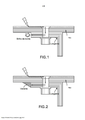
[005] A Figura 1 mostra um trajeto de corrente crítica potencialdurante um evento de queda de raio em uma caixa de asa compósita. O fenômeno de brilho de borda parece mais crítico quando a resina entre as dobras de reforço de fibra é altamente resistiva e, consequentemente, a corrente tende a não fluir entre as dobras. Se a condutividade na direção z for muito baixa, quedas de tensão significativas podem ser produzidas entre as dobras durante a queda de raio, aumentando, assim, o risco de brilho de borda.[005] Figure 1 shows a potential critical current path during a lightning strike event in a composite wing box. The edge glow phenomenon seems more critical when the resin between the fiber reinforcement plies is highly resistive and, consequently, current tends not to flow between the plies. If the conductivity in the z-direction is too low, significant voltage drops can be produced between bends during lightning strike, thus increasing the risk of edge glare.
[006] Conforme conhecido por aqueles versados na técnica, ofenômeno de brilho de borda está associado a ejeções de elétron de superfície ou geração de plasma nas bordas compósitas e frequentemente aparece como um tipo de explosão de resina. A incerteza em relação à natureza desse fenômeno impôs diversos cuidados em relação às capacidades de ignição de vapores de combustível durante um evento de queda de raio.[006] As known to those skilled in the art, the edge glow phenomenon is associated with surface electron ejections or plasma generation at the composite edges and often appears as a type of resin explosion. Uncertainty regarding the nature of this phenomenon imposed several precautions regarding the ignition capabilities of fuel vapors during a lightning strike event.
[007] Uma solução convencional é aplicar um vedante no tanque de combustível (consultar a Figura 2). Um exemplo de tal vedante de tanque de combustível é o vedante PR 1776 Classe B da LE JOINT FRANCAIS. No entanto, tal método leva a peso adicional e não é sempre eficaz devido à falta de padronização e dificuldades na aplicação de vedante. Ao longo do tempo, o vedante torna-se ineficaz devido ao envelhecimento ou pode ser totalmente removido pelo combustível no tanque. Além disso, uma queda de raio pode resultar na geração de gases de alta pressão na borda de corte que podem despedaçar a vedação de borda. Permanece uma necessidade de um material compósito multifuncional que trata o problema do brilho de borda discutido acima enquanto fornece boas propriedades mecânicas, tal como resistência a impacto e delaminação.[007] A conventional solution is to apply a seal to the fuel tank (see Figure 2). An example of such a fuel tank seal is the LE JOINT FRANCAIS PR 1776 Class B seal. However, such a method carries additional weight and is not always effective due to lack of standardization and difficulties in sealant application. Over time, the seal becomes ineffective due to aging or can be completely removed by the fuel in the tank. Additionally, a lightning strike can result in the generation of high pressure gases at the cutting edge that can shatter the edge seal. There remains a need for a multifunctional composite material that addresses the edge gloss problem discussed above while providing good mechanical properties such as impact strength and delamination.
[008] São revelados no presente documento materiais compósitoscom condutividade elétrica e propriedades de resistência ao impacto. Esses materiais compósitos contêm partículas de endurecimento poliméricas e estruturas à base de carbono nanodimensionadas na região interlaminar entre camadas adjacentes de fibras de reforço. As partículas de endurecimento poliméricas são substancialmente insolúveis na resina de matriz termofixa na região interlaminar durante a cura dos materiais compósitos e permanecem como partículas discretas na região interlaminar dos materiais compósitos curados.[008] In this document, composite materials with electrical conductivity and impact resistance properties are disclosed. These composite materials contain polymeric stiffening particles and nanosized carbon-based structures in the interlaminar region between adjacent layers of reinforcing fibers. The polymeric hardening particles are substantially insoluble in the thermosetting matrix resin in the interlaminar region during the curing of the composite materials and remain as discrete particles in the interlaminar region of the cured composite materials.
[009] A Figura 1 mostra o trajeto de corrente típico durante umevento de queda de raio em uma caixa de asa compósita que gera o fenômeno de “brilho de borda”.[009] Figure 1 shows the typical current path during a lightning strike event in a composite wing box that generates the phenomenon of "edge glow".
[010] A Figura 2 mostra um vedante aplicado à borda de tampadelongarina da construção típica de uma asa compósita.[010] Figure 2 shows a sealant applied to the wing cap edge of the typical construction of a composite wing.
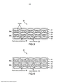
[011] A Figura 3 ilustra esquematicamente um material compósitocurável com regiões interlaminares que contêm partículas de endurecimento e nanomateriais de carbono, de acordo com uma modalidade da presente revelação.[011] Figure 3 schematically illustrates a curable composite material with interlaminar regions that contain hardening particles and carbon nanomaterials, according to an embodiment of the present disclosure.
[012] A Figura 4 ilustra esquematicamente um material compósitocurável com regiões interlaminares que contêm partículas de endurecimento e os nanomateriais de carbono uniformemente dispersos na matriz, de acordo com outra modalidade da presente revelação.[012] Figure 4 schematically illustrates a curable composite material with interlaminar regions that contain hardening particles and carbon nanomaterials uniformly dispersed in the matrix, according to another embodiment of the present disclosure.
[013] A Figura 5 e a Figura 6 ilustram um método para fabricar ummaterial compósito de acordo com uma modalidade.[013] Figure 5 and Figure 6 illustrate a method to manufacture a composite material according to a modality.
[014] A Figura 7 e a Figura 8 ilustram um método para fabricar ummaterial compósito de acordo com outra modalidade da presente revelação.[014] Figure 7 and Figure 8 illustrate a method for manufacturing a composite material according to another embodiment of the present disclosure.
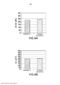
[015] As Figuras 9A e 9B mostram as propriedades mecânicas deum laminado compósito modificado com nanotubos de carbono (CNTs) versus aqueles de um laminado compósito não modificado.[015] Figures 9A and 9B show the mechanical properties of a composite laminate modified with carbon nanotubes (CNTs) versus those of an unmodified composite laminate.
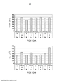
[016] As Figuras 10A e 10B mostram o efeito de diferentespartículas de endurecimento poliméricas sobre as propriedades mecânicas de materiais compósitos modificados com CNT.[016] Figures 10A and 10B show the effect of different polymeric hardening particles on the mechanical properties of composite materials modified with CNT.
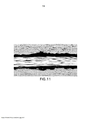
[017] A Figura 11 mostra uma imagem de micrógrafo do cortetransversal de um laminado curado (4b) que contém CNTs e partículas de poliftalamida.[017] Figure 11 shows a micrograph image of the cross section of a cured laminate (4b) that contains CNTs and polyphthalamide particles.
[018] A Figura 12 mostra uma imagem de micrógrafo do cortetransversal de um laminado curado (4a) que contém CNTs e partículas de poli-imida aromática.[018] Figure 12 shows a micrograph image of the cross section of a cured laminate (4a) that contains CNTs and aromatic polyimide particles.
[019] A Figura 13 mostra o efeito de diferentes partículas deendurecimento poliméricas na condutividade CC na direção z de laminados compósitos modificados com CNT e naqueles não modificados com CNTs. DESCRIÇÃO DETALHADA[019] Figure 13 shows the effect of different polymeric hardening particles on the z-direction CC conductivity of composite laminates modified with CNT and those not modified with CNTs. DETAILED DESCRIPTION
[020] É amplamente aceito na indústria aeroespacial que dois dosrequisitos de projeto principais para estruturas compósitas de aeronaves são sua resistência a eventos de impacto específicos e sua tolerância a falhas catastróficas causadas por propagação de dano após o impacto.[020] It is widely accepted in the aerospace industry that two of the main design requirements for composite aircraft structures are their resistance to specific impact events and their tolerance to catastrophic failures caused by propagation of damage after impact.
[021] A região interlaminar de um laminado compósito apresenta umdos mecanismos de falha mais desafiadores de tratar. A delaminação de tal laminado compósito é um modo de falha importante para materiais compósitos. A delaminação ocorre quando duas camadas laminadas se separam uma da outra. Os fatores limitantes de projeto importantes incluem energia necessária para iniciar a delaminação e a energia necessária para propagá-la.[021] The interlaminar region of a composite laminate presents one of the most challenging failure mechanisms to treat. Delamination of such a composite laminate is an important failure mode for composite materials. Delamination occurs when two laminated layers separate from each other. Important design limiting factors include energy required to initiate delamination and energy required to propagate it.
[022] A necessidade de aprimorar o desempenho de resistência aoimpacto de estruturas compósitas, especialmente para estruturas primárias de aeronaves, desencadeou o desenvolvimento de uma nova geração de materiais compósitos endurecidos com partículas interlaminares. Tal solução tecnológica fornece alta resistência ao impacto a compósitos reforçados com fibra de carbono, mas também cria uma região interlaminar de isolamento elétrico entre dobras adjacentes, resultando em uma redução significativa na condutividade elétrica da estrutura compósita geral especialmente na direção z. A “direção z” refere-se à direção ortogonal ao plano em que as fibras de reforço são dispostas em uma estrutura compósita ou o eixo geométrico através da espessura da estrutura compósita.[022] The need to improve the impact strength performance of composite structures, especially for primary aircraft structures, has triggered the development of a new generation of composite materials hardened with interlaminar particles. Such a technological solution provides high impact resistance to carbon fiber reinforced composites, but also creates an interlaminar region of electrical insulation between adjacent bends, resulting in a significant reduction in the electrical conductivity of the overall composite structure especially in the z direction. The “z direction” refers to the direction orthogonal to the plane in which the reinforcing fibers are disposed in a composite structure or the geometric axis through the thickness of the composite structure.
[023] A condutividade elétrica de materiais compósitos pode seraprimorada incorporando-se diferentes materiais condutivos, tais como partículas condutivas, na resina de matriz do compósito polimérico reforçado com fibra, ou nas regiões interlaminares de uma estrutura compósita com múltiplas camadas, por exemplo, laminação de pré-impregnado. Por exemplo, cargas metálicas podem ser adicionadas em carregamentos altos para aumentar a condutividade elétrica da resina, mas isso lava a ganho de peso significativo e redução nas propriedades relacionadas à resistência ao impacto, tal como Resistência à Compressão Após Impacto (CAI) e tenacidade da fratura em modo I e II (GIc e GIIc). Como tal, as soluções do estado da técnica são tais que a condutividade na direção z de um compósito pode ser aprimorada, mas não, simultaneamente, seu desempenho mecânico. Um compósito curado (por exemplo, laminação de pré-impregnado) com desempenho de impacto aprimorado é aquele com CAI aprimorada e tenacidade da fratura (GIc e GIIc). A CAI mede a capacidade de um material compósito de tolerar dano. No teste para medir CAI, o compósito curado é submetido a um impacto de uma dada energia e, então, carregado em compressão. A área de dano e a profundidade de entalhe são medidas após o impacto e antes do teste de compressão. Durante esse teste, o material compósito é constrito para garantir que nenhuma instabilidade elástica esteja ocorrendo, e a resistência do material compósito é registrada.[023] The electrical conductivity of composite materials can be improved by incorporating different conductive materials, such as conductive particles, in the fiber-reinforced polymer composite matrix resin, or in the interlaminar regions of a composite structure with multiple layers, for example, lamination of prepreg. For example, metallic fillers can be added at high loads to increase the electrical conductivity of the resin, but this leads to significant weight gain and reduction in impact-related properties such as Compressive Strength After Impact (CAI) and toughness of the fracture in mode I and II (GIc and GIIc). As such, prior art solutions are such that the z-direction conductivity of a composite can be improved, but not, simultaneously, its mechanical performance. A cured composite (eg prepreg lamination) with improved impact performance is one with improved CAI and fracture toughness (GIc and GIIc). CAI measures the ability of a composite material to tolerate damage. In the test to measure CAI, the cured composite is subjected to an impact of a given energy and then loaded in compression. The area of damage and depth of notch are measured after impact and before the compression test. During this test, the composite material is constricted to ensure that no elastic instability is occurring, and the strength of the composite material is recorded.
[024] A tenacidade da fratura é uma propriedade que descreve acapacidade de um material que contém uma rachadura de resistir à fratura e é uma das propriedades mais importantes de um material para aplicações aeroespaciais. A tenacidade da fratura é uma forma quantitativa de expressar a resistência de um material à fratura frágil quando uma rachadura está presente.[024] Fracture toughness is a property that describes the ability of a material that contains a crack to resist fracture and is one of the most important properties of a material for aerospace applications. Fracture toughness is a quantitative way of expressing a material's brittle fracture resistance when a crack is present.
[025] A resistência à fratura pode ser quantificada como taxa deliberação de energia de deformação (Gc), que é a energia dissipada durante a fratura por unidade de área superficial de fratura recém-criada. Gc inclui GIC (Modo 1 - modo de abertura) ou Gnc(Modo II - cisalhamento no plano). O subscrito “Ic” denota abertura de rachadura de Modo I, que é formada sob uma tensão de tração normal perpendicular à rachadura, e o subscrito “IIc” denota rachadura de Modo II produzida por uma tensão de cisalhamento produzida por uma tensão de cisalhamento que atua paralela ao plano da rachadura e perpendicular à frente da rachadura. A iniciação e o crescimento de uma delaminação são frequentemente determinados examinando-se a tenacidade da fratura de Modo I e Modo II.[025] Fracture strength can be quantified as rate of deformation energy release (Gc), which is the energy dissipated during fracture per unit of newly created fracture surface area. Gc includes GIC (Mode 1 - opening mode) or Gnc (Mode II - plane shear). The subscript "Ic" denotes Mode I crack opening, which is formed under a normal tensile stress perpendicular to the crack, and the subscript "IIc" denotes Mode II crack produced by a shear stress produced by a shear stress that acts parallel to the plane of the crack and perpendicular to the front of the crack. The initiation and growth of a delamination is often determined by examining the Mode I and Mode II fracture toughness.
[026] Revelou-se que a combinação de nanomateriais de carbono e determinadas partículas poliméricas na região interlaminar de um material compósito com múltiplas camadas produz um efeito sinérgico que inclui um aprimoramento na condutividade na direção z e, simultaneamente, um aprimoramento em CAI e GIc. O efeito sinérgico foi encontrado combinando- se os efeitos positivos dos nanomateriais de carbono com os efeitos positivos das partículas de endurecimento, assim a interação desses componentes no material compósito produz um efeito maior que a soma de seus efeitos individuais.[026] It has been revealed that the combination of carbon nanomaterials and certain polymeric particles in the interlaminar region of a multilayer composite material produces a synergistic effect that includes an improvement in conductivity in the z direction and, simultaneously, an improvement in CAI and GIc. The synergistic effect was found by combining the positive effects of carbon nanomaterials with the positive effects of hardening particles, so the interaction of these components in the composite material produces an effect greater than the sum of their individual effects.
[027] É revelado no presente documento um material compósitomultifuncional e curável, que pode ser usado com sucesso nessas aplicações de aeronaves em que alto desempenho mecânico e alta condutividade elétrica são exigidos. No estado curado, a condutividade elétrica aprimorada do material compósito pode funcionar para difundir ou dissipar as correntes elétricas, tais como aquelas geradas por uma queda de raio, sobre uma área maior de uma estrutura compósita produzida a partir do material compósito, reduzindo, assim, a probabilidade de um dano catastrófico a porções localizadas da estrutura compósita. Como tal, usar esse material compósito multifuncional pode ser uma solução eficaz para mitigar o efeito direto da queda de raio e para impedir o fenômeno de brilho de borda nos compósitos discutidos acima. Além disso, o material compósito curado fornece o benefício adicional de blindagem eletromagnética.[027] It is disclosed in this document a multifunctional and curable composite material, which can be used successfully in those aircraft applications where high mechanical performance and high electrical conductivity are required. In the cured state, the improved electrical conductivity of the composite material can function to diffuse or dissipate electrical currents, such as those generated by a lightning strike, over a larger area of a composite structure produced from the composite material, thereby reducing the probability of catastrophic damage to localized portions of the composite structure. As such, using this multifunctional composite material can be an effective solution to mitigate the direct effect of lightning strike and to prevent the edge shine phenomenon in the composites discussed above. In addition, the cured composite material provides the added benefit of electromagnetic shielding.
[028] Um aspecto da presente revelação está direcionado a ummaterial compósito curável composto por duas ou mais camadas de fibras de reforço que foram infundidas ou impregnadas com uma resina de matriz curável, de preferência, uma resina termofixa. A região interlaminar entre camadas adjacentes de fibras de reforço contém uma resina de matriz curável com nanomateriais de carbono dispersos por toda a mesma e partículas de endurecimento poliméricas incorporadas na mesma resina de matriz. Os nanomateriais de carbono são significativamente menores em tamanho em comparação às partículas de endurecimento poliméricas. As partículas poliméricas de endurecimento são substancialmente insolúveis na resina de matriz mediante a cura do material compósito e permanecem como partículas discretas na região interlaminar após a cura. Em certas modalidades, as partículas de endurecimento poliméricas são partículas expansíveis. É preferencial que a região interlaminar seja livre de quaisquer partículas termoplásticas solúveis que se dissolvem na resina de matriz mediante a cura.[028] One aspect of the present disclosure is directed to a curable composite material composed of two or more layers of reinforcing fibers that have been infused or impregnated with a curable matrix resin, preferably a thermosetting resin. The interlaminar region between adjacent layers of reinforcing fibers contains a curable matrix resin with carbon nanomaterials dispersed throughout and polymeric stiffening particles incorporated in the same matrix resin. Carbon nanomaterials are significantly smaller in size compared to polymeric hardening particles. The polymeric hardening particles are substantially insoluble in the matrix resin upon curing of the composite material and remain as discrete particles in the interlaminar region after curing. In certain embodiments, the polymeric hardening particles are expandable particles. It is preferred that the interlaminar region is free of any soluble thermoplastic particles that dissolve in the matrix resin upon curing.
[029] A resina na região interlaminar (sem nanomateriais epartículas de endurecimento) pode ser igual ou diferente em relação à resina de matriz que impregna as fibras de reforço. Em algumas modalidades, a resina de matriz que impregna as fibras de reforço também contém nanomateriais de carbono dispersos na mesma.[029] The resin in the interlaminar region (without nanomaterials and hardening particles) can be the same or different in relation to the matrix resin that impregnates the reinforcing fibers. In some embodiments, the matrix resin that impregnates the reinforcing fibers also contains carbon nanomaterials dispersed therein.
[030] A Figura 3 ilustra esquematicamente um material compósitocurável 20 de acordo com uma modalidade da presente revelação. O material compósito 20 contém regiões interlaminares 20a e 20b formadas entre as camadas 21, 22, 23 de fibras de reforço que foram infundidas ou impregnadas com uma resina de matriz curável. Cada uma das regiões interlaminares 20a e 20b contém uma resina de matriz curável (24a, 24b, respectivamente) com nanomateriais de carbono 25 dispersos na mesma e partículas de endurecimento poliméricas 26 incorporadas na mesma resina de matriz. A composição de resina (sem nanomateriais e partículas de endurecimento) da resina interlaminar 24a e 24b pode ser igual ou diferente em relação àquela da resina de matriz que impregna as camadas de fibra 21, 22, 23. Quando a resina interlaminar (24a, 24b) é similar àquela da resina de matriz que impregna as camadas de fibra 21, 22, 23, as matrizes de resina contêm uma ou mais resinas termofixas em comum. As partículas de endurecimento poliméricas 26 podem estar posicionadas lado a lado e juntas formam uma única camada de partículas. Dessa maneira, a profundidade da região interlaminar é determinada pelos tamanhos das partículas. De preferência, as partículas de endurecimento 26 são similares em tamanho (por exemplo, partículas esféricas que têm aproximadamente o mesmo diâmetro), e a profundidade da região interlaminar é aproximadamente igual ou ligeiramente maior que o diâmetro médio das partículas de endurecimento 26.[030] Figure 3 schematically illustrates a curable
[031] A Figura 4 ilustra esquematicamente um material compósitocurável 40 de acordo com outra modalidade da presente revelação. O material compósito 40 contém as regiões interlaminares 40a e 40b formadas entre as camadas 41, 42, 43 de fibras de reforço, e as regiões interlaminares contêm partículas de endurecimento poliméricas 46. As fibras de reforço (41, 42, 43) e partículas poliméricas 46 são infundidas com ou incorporadas dentro de uma resina de matriz curável que contêm nanomateriais de carbono 45 dispersos na mesma. Como na modalidade mostrada na Figura 3, as partículas poliméricas 46 podem estar posicionadas lado a lado e juntas formam uma única camada de partículas. Além disso, a profundidade da região interlaminar pode ser determinada pelos tamanhos das partículas. De preferência, as partículas de endurecimento 46 são similares em tamanho (por exemplo, partículas esféricas que têm aproximadamente o mesmo diâmetro), e a profundidade da região interlaminar é aproximadamente igual ou ligeiramente maior que o diâmetro médio das partículas de endurecimento 46.[031] Figure 4 schematically illustrates a curable
[032] Mediante a cura, os materiais compósitos curados, de acordocom as modalidades reveladas no presente documento, têm as seguintes propriedades: condutividade elétrica na direção z maior que 1 S/m (siemens por metro) conforme medido em condições CC de acordo com um método de teste de 4 sondas, CAI após impacto a 30 J maior que 250 MPa conforme medido em conformidade com a norma ASTM7136/37 e resistência à fratura interlaminar sob modo I (GIc) maior que 300 J/m2 conforme medida em conformidade com a norma EN6033.[032] Upon curing, composite materials cured, according to the modalities disclosed in this document, have the following properties: electrical conductivity in the z direction greater than 1 S/m (siemens per meter) as measured under DC conditions according to a 4-probe test method, CAI after impact at 30 J greater than 250 MPa as measured in accordance with ASTM7136/37 and mode I interlaminar fracture resistance (GIc) greater than 300 J/m2 as measured in accordance with the EN6033 standard.
[033] O termo “nanomateriais de carbono” ou estruturas à base de carbono nanodimensionadas, conforme usado no presente documento, refere- se a materiais que têm pelo menos uma dimensão menor que cerca de 0,1 micrômetro (<100 nanômetros) e composta inteira ou principalmente por átomos de carbono dispostos, na escala molecular, em pentágonos ou hexágonos, ou ambos.[033] The term "carbon nanomaterials" or nanosized carbon-based structures, as used herein, refers to materials that have at least one dimension less than about 0.1 micrometer (<100 nanometers) and composite entirely or mainly by carbon atoms arranged, on the molecular scale, in pentagons or hexagons, or both.
[034] As estruturas de carbono nanodimensionadas podem ter umarazão de aspecto de 50:1 a 5.000:1. O termo “razão de aspecto”, conforme usado no presente documento, refere-se à razão entre a dimensão mais longa e a dimensão mais curta de um corpo tridimensional. Esse termo é aplicável a estruturas de qualquer formato e tamanho. Quando esse termo é usado em relação a partículas esféricas ou substancialmente esféricas, a razão relevante poderia ser aquela entre o diâmetro de maior corte transversal e o diâmetro de menor corte transversal do corpo esférico. Como um exemplo, uma partícula perfeitamente esférica poderia ter uma razão de aspecto de 1:1.[034] Nanosized carbon structures can have an aspect ratio of 50:1 to 5,000:1. The term "aspect ratio" as used herein refers to the ratio of the longest dimension to the shortest dimension of a three-dimensional body. This term is applicable to structures of any shape and size. When this term is used in relation to spherical or substantially spherical particles, the relevant ratio could be that between the largest cross-sectional diameter and the smallest cross-sectional diameter of the spherical body. As an example, a perfectly spherical particle could have an aspect ratio of 1:1.
[035] As estruturas de carbono nanodimensionadas para o propósitodestinado no presente documento incluem, porém, sem limitação, nanotubos de carbono, nanofibras de carbono, nanocordas de carbono, nanolaços de carbono, nanofibrilas de carbono, nanoagulhas de carbono, nanofolhas de carbono, nano-hastes de carbono, nanocones de carbono, nanorrolos de carbono (formatos similares a rolo) e nano-ohms de carbono, negro de fumo, nanoplaquetas ou nanopontos de grafite, grafenos e outros tipos de materiais de fulereno. Qualquer um desses materiais de fulereno pode ter um revestimento metálico parcial ou total. As nanopartículas podem ser de quaisquer formatos tridimensionais adequados, incluindo, por exemplo, esférico, elipsoidal, esferoide, discoidal, dendrítico, hastes, discos, cuboide ou poliédrico.[035] The nanosized carbon structures for the purpose intended in this document include, but are not limited to, carbon nanotubes, carbon nanofibers, carbon nanocords, carbon nanoties, carbon nanofibrils, carbon nanoneedles, carbon nanosheets, nano -carbon rods, carbon nanocones, carbon nanorolls (roll-like shapes) and carbon nano-ohms, carbon black, graphite nanoplates or nanodots, graphenes and other types of fullerene materials. Any of these fullerene materials can have a partial or full metallic coating. The nanoparticles can be of any suitable three-dimensional shapes, including, for example, spherical, ellipsoidal, spheroid, discoidal, dendritic, rods, disks, cuboid or polyhedral.
[036] Os nanomateriais de carbono preferenciais são nanotubos decarbono (CNTs). Tipicamente, os CNTs são tubulares, estruturas do tipo filamento que têm diâmetros externos na faixa de 0,4 nm a cerca de 100 nm, de preferência, o diâmetro externo é menor que 50 nm e, de maior preferência, menor que 25 nm.[036] The preferred carbon nanomaterials are carbon nanotubes (CNTs). Typically, CNTs are tubular, filament-like structures that have outside diameters in the range of 0.4 nm to about 100 nm, preferably the outside diameter is less than 50 nm and most preferably less than 25 nm.
[037] Os CNTs podem ser de qualquer quiralidade. Nanotubos dotipo poltrona são contemplados. Além disso, os CNTs podem ser nanotubos semicondutores ou qualquer outro tipo que exiba condutividade elétrica. Os CNTs adequados podem incluir nanotubos de carbono com parede única (SWCNTs), nanotubos de carbono com parede dupla (DWCNTs) e nanotubos de carbono com múltiplas paredes (MWCNTs). Os nanomateriais de carbono preferenciais são MWCNTs.[037] The CNTs can be of any chirality. Armchair type nanotubes are contemplated. Furthermore, CNTs can be semiconductor nanotubes or any other type that exhibit electrical conductivity. Suitable CNTs can include single-walled carbon nanotubes (SWCNTs), double-walled carbon nanotubes (DWCNTs) and multi-walled carbon nanotubes (MWCNTs). Preferred carbon nanomaterials are MWCNTs.
[038] Os nanomateriais de carbono para os propósitos destinados nopresente documento podem estar presentes na faixa de 0,1% em peso a 10% em peso do teor de resina total no material compósito, de preferência, entre 0,5% em peso a 2% em peso e, de maior preferência, na faixa de 1% em peso a 1,5% em peso. Conforme usado no presente documento, “% em peso” refere-se à porcentagem em peso.[038] Carbon nanomaterials for the purposes intended herein may be present in the range of 0.1% by weight to 10% by weight of the total resin content in the composite material, preferably between 0.5% by weight to 2% by weight and more preferably in the range of 1% by weight to 1.5% by weight. As used herein, "% by weight" refers to percent by weight.
[039] As partículas de endurecimento poliméricas que são adequadaspara os propósitos no presente documento incluem partículas termoplásticas ou elastoméricas. Conforme discutido anteriormente, as partículas de endurecimento adequadas são partículas que são substancialmente insolúveis na resina de matriz termofixa dos materiais compósitos durante a cura dos mesmos e permanecem como partículas discretas na resina de matriz curada após a cura. Em certas modalidades, as partículas de endurecimento poliméricas são também partículas expansíveis na resina de matriz termofixa do material compósito durante a cura. Além disso, as partículas de endurecimento poliméricas não têm um revestimento não polimérico, tal como metal.[039] Polymeric hardening particles that are suitable for the purposes herein include thermoplastic or elastomeric particles. As discussed above, suitable hardening particles are particles that are substantially insoluble in the thermosetting matrix resin of the composite materials during the curing thereof and remain as discrete particles in the cured matrix resin after curing. In certain embodiments, the polymeric hardening particles are also expandable particles in the thermosetting matrix resin of the composite material during curing. Furthermore, polymeric hardening particles do not have a non-polymeric coating, such as metal.
[040] É preferencial que as partículas de endurecimento sejamuniformemente dispersas na região interlaminar formada entre camadas adjacentes de fibras de reforço a um teor de 2% a 20% com base no peso da resina de matriz total contida no material compósito, de preferência, dentro da faixa de 5% a 15% e, de maior preferência, dentro da faixa de 5% a 12%.[040] It is preferred that the hardening particles are evenly dispersed in the interlaminar region formed between adjacent layers of reinforcing fibers at a content of 2% to 20% based on the weight of the total matrix resin contained in the composite material, preferably within in the range of 5% to 15% and more preferably within the range of 5% to 12%.
[041] As partículas de endurecimento poliméricas podem ser dequalquer formato tridimensional, porém, é preferencial que as mesmas sejam substancialmente esféricas. É também preferencial que as partículas de endurecimento tenham uma razão de aspecto menor que 5:1, de preferência, a razão de aspecto é cerca de 1:1. Em referência às partículas de endurecimento, o termo “razão de aspecto” refere-se à razão entre a maior dimensão de corte transversal e a menor dimensão de corte transversal da partícula.[041] The polymeric hardening particles can be of any three-dimensional shape, however, it is preferred that they are substantially spherical. It is also preferred that the hardening particles have an aspect ratio of less than 5:1, preferably the aspect ratio is about 1:1. In reference to hardening particles, the term "aspect ratio" refers to the ratio of the largest cross-sectional dimension to the smallest cross-sectional dimension of the particle.
[042] Para partículas esféricas (razão de aspecto deaproximadamente 1:1), o tamanho médio de partícula refere-se a seu diâmetro. Para partículas não esféricas, o tamanho médio de partícula refere- se à maior dimensão de corte transversal das partículas.[042] For spherical particles (approx. 1:1 aspect ratio), the average particle size refers to its diameter. For non-spherical particles, mean particle size refers to the largest cross-sectional dimension of the particles.
[043] Para os propósitos revelados no presente documento, aspartículas de endurecimento poliméricas podem ter um tamanho médio de partícula (d50) menor que 100 μm, de preferência, dentro da faixa de 50 μm a 90 μm, de maior preferência, 10 μm a 40 μm, conforme medido por uma técnica de difração de laser, por exemplo, com o uso de MalvernMastersizer 2000 que opera na faixa de 0,002 nanômetro a 2.000 micra.[043] For the purposes disclosed herein, polymeric hardening particles may have an average particle size (d50) less than 100 µm, preferably within the range of 50 µm to 90 µm, more preferably 10 µm to 40 µm, as measured by a laser diffraction technique, for example using a MalvernMastersizer 2000 operating in the range of 0.002 nanometer to 2000 micron.
[044] “d50” representa a mediana da distribuição de tamanho departícula ou, alternativamente, é o valor na distribuição de modo que 50% das partículas tenham um tamanho de partícula desse valor ou menor.[044] “d50” represents the median of the particle size distribution or, alternatively, is the value in the distribution such that 50% of the particles have a particle size of this value or smaller.
[045] Além disso, as partículas de endurecimento poliméricas sãomaiores em tamanho em comparação às nanoestruturas de carbono. É preferencial que o tamanho médio de partícula (d50) das partículas de endurecimento poliméricas seja pelo menos 100 vezes maior que a menor dimensão da nanoestrutura de carbono.[045] In addition, polymeric hardening particles are larger in size compared to carbon nanostructures. It is preferred that the average particle size (d50) of the polymeric hardening particles is at least 100 times larger than the smallest dimension of the carbon nanostructure.
[046] Como um exemplo, quando as nanoestruturas de carbono são nanotubos de carbono, o tamanho médio de partícula (d50) da partícula de endurecimento é pelo menos 100 vezes maior que o diâmetro dos nanotubos de carbono.[046] As an example, when the carbon nanostructures are carbon nanotubes, the average particle size (d50) of the hardening particle is at least 100 times larger than the diameter of the carbon nanotubes.
[047] Determinar se determinadas partículas são insolúveis ousolúveis refere-se à solubilidade das partículas em um sistema de resina particular em que as mesmas residem. O sistema de resina pode incluir uma ou mais resinas termofixas, agentes de cura e/ou catalisadores e quantidades espelhadas de aditivos opcionais para modificar as propriedades da resina de matriz não curada ou curada.[047] Determining whether certain particles are insoluble or soluble refers to the solubility of the particles in a particular resin system in which they reside. The resin system can include one or more thermosetting resins, curing agents and/or catalysts and mirrored amounts of optional additives to modify the properties of the uncured or cured matrix resin.
[048] Microscopia de estágio quente pode ser usada para determinarse uma partícula é insolúvel, parcialmente solúvel ou expansível em um sistema de resina. Em primeiro lugar, uma amostra de partículas poliméricas secas (que não são combinadas com uma resina) é caracterizada por microscopia, e as imagens analisadas com o uso do software ImageJ do NationalInstitutesof Health (Bethesda, Maryland, EUA) para determinar o tamanho médio de partícula e o volume. Em segundo lugar, uma amostra de partículas é dispersa na resina de matriz desejada por meio de misturação mecânica. Em terceiro lugar, uma amostra da mistura resultante é colocada em uma lâmina para microscópio, que é, então, colocada em uma configuração de estágio quente sob um microscópio. Então, a amostra é aquecida até a temperatura de cura desejada na taxa de rampa desejada, e qualquer alteração em tamanho, volume ou formato da partícula é registrada continuamente a 10 quadros por segundo. O diâmetro é normalmente medido para partícula esférica enquanto o lado mais longo é medido no caso daquelas não esféricas para determinar alterações em tamanho e volume com o uso do software ImageJ. Todo teste de estágio quente pode ser executado a um carregamento de partícula de 10% em peso em uma resina de matriz que não contém curativo ou catalisador.[048] Hot stage microscopy can be used to determine whether a particle is insoluble, partially soluble, or expandable in a resin system. First, a sample of dry polymeric particles (which are not combined with a resin) is characterized by microscopy, and the images analyzed using ImageJ software from the NationalInstitutesof Health (Bethesda, Maryland, USA) to determine the mean size of particle and volume. Second, a sample of particles is dispersed into the desired matrix resin through mechanical mixing. Third, a sample of the resulting mixture is placed on a microscope slide, which is then placed in a hot stage setup under a microscope. The sample is then heated to the desired cure temperature at the desired ramp rate, and any change in particle size, volume, or shape is continuously recorded at 10 frames per second. Diameter is typically measured for spherical particles while the longer side is measured for non-spherical ones to determine changes in size and volume using ImageJ software. All hot stage testing can be performed at a 10 wt% particle loading on a matrix resin that does not contain a curative or catalyst.
[049] Quando partículas de endurecimento são submetidas à análise por microscopia de estágio quente acima, e a alteração em diâmetro ou volume da partícula é zero ou menos que 5%, em comparação às partículas “secas” originais, então, a partícula é considerada como sendo insolúvel e não intumescente. Quando a partícula de endurecimento é submetida à análise por microscopia de estágio quente acima e há um aumento em diâmetro ou volume da partícula em mais de 5%, então, a partícula é considerada como sendo “intumescente” assim como insolúvel. O intumescimento é causado pela infusão da resina circundante na superfície externa da partícula.[049] When hardening particles are subjected to hot stage microscopy analysis above, and the change in particle diameter or volume is zero or less than 5% compared to the original "dry" particles, then the particle is considered as being insoluble and not intumescent. When the hardening particle is subjected to the above hot stage microscopy analysis and there is an increase in particle diameter or volume by more than 5%, then the particle is considered to be “swellable” as well as insoluble. The swelling is caused by the infusion of the surrounding resin on the outer surface of the particle.
[050] Em algumas modalidades, as partículas insolúveis incluempartículas que se fundem durante a análise por microscopia de estágio quente, mas são incompatíveis com a resina de matriz e, portanto, reformam-se em partículas discretas mediante resfriamento. Para propósitos analíticos apenas, as partículas insolúveis podem fluir durante a análise por microscopia de estágio quente, e o grau de cristalinidade pode também mudar.[050] In some embodiments, insoluble particles include particles that fuse during analysis by hot stage microscopy, but are incompatible with the matrix resin and therefore reform into discrete particles upon cooling. For analytical purposes only, insoluble particles may flow during analysis by hot stage microscopy, and the degree of crystallinity may also change.
[051] Nos casos em que o diâmetro ou volume podem ser difíceis dedeterminar, uma análise alternativa pode ser usada. Um painel compósito quase isotrópico de 16 dobras produzidas a partir de fitas de pré-impregnado unidirecional e contendo um carregamento de partícula de 10% com base no peso da resina de matriz total nas regiões interlaminares ricas em resina pode ser fabricado de acordo com um cronograma de cura e, então, o painel curado é cortado no sentido de corte transversal para avaliação por microscopia. Se as partículas permanecerem como partículas discerníveis e discretas após a cura, então, as partículas são consideradas como sendo partículas insolúveis. Se as partículas dissolverem completamente tanto na região interlaminar como na matriz que cerca o leito de fibras e não forem discerníveis como partículas discretas mediante resfriamento, então, as partículas não são consideradas partículas interlaminares insolúveis.[051] In cases where diameter or volume may be difficult to determine, an alternative analysis can be used. A 16 ply quasi isotropic composite panel produced from unidirectional prepreg tapes and containing a 10% particle loading based on the weight of the total matrix resin in the resin-rich interlaminar regions can be fabricated according to a schedule of curing and then the cured panel is cut in the cross-sectional direction for evaluation by microscopy. If the particles remain as discernible and discrete particles after curing, then the particles are considered to be insoluble particles. If the particles completely dissolve in both the interlaminar region and the matrix surrounding the fiber bed and are not discernible as discrete particles upon cooling, then the particles are not considered to be insoluble interlaminar particles.
[052] Para resina de matriz à base de epóxi, a composição departículas poliméricas insolúveis pode conter pelo menos um polímero selecionado dentre: poliamidaimida (PAl), poliamidas alifáticas (PA), poliftalamida (PPA), poliariletercetonas (PAEK), tais como polieteretercetona (PEEK) e polietercetonacetona (PEKK), sulfeto de polifenileno (PPS), copolímeros de cristal líquido (LCPs), copolímeros dos mesmos e derivados dos mesmos. Em algumas modalidades, a composição das partículas poliméricas contém pelo menos um polímero elastomérico ou material selecionado dentre: polibutadieno reticulado, poliacrílico, poliacrilonitrila, poliestireno, copolímeros dos mesmos, e derivados dos mesmos (tal como DuoMod DP5045 vendido junto à ZeonChemicalsInc).[052] For epoxy-based matrix resin, the composition of insoluble polymeric particles may contain at least one polymer selected from: polyamideimide (PAl), aliphatic polyamides (PA), polyphthalamide (PPA), polyaryletherketones (PAEK), such as polyetheretherketone (PEEK) and polyetherketone ketone (PEKK), polyphenylene sulfide (PPS), liquid crystal copolymers (LCPs), copolymers thereof and derivatives thereof. In some embodiments, the polymer particle composition contains at least one elastomeric polymer or material selected from: cross-linked polybutadiene, polyacrylic, polyacrylonitrile, polystyrene, copolymers thereof, and derivatives thereof (such as DuoMod DP5045 sold from ZeonChemicalsInc).
[053] Em modalidades preferenciais, as partículas insolúveis sãopartículas termoplásticas insolúveis que não dissolvem durante o processo de cura e permanecem dentro das regiões interlaminares do material compósito curado. Os exemplos de partículas termoplásticas insolúveis adequadas incluem partículas de poliamidaimida (PAl) e partículas de poliamida (PA) (por exemplo, náilon) ou partículas de poliftalamida (PPA), que são insolúveis em sistema de resina epóxi durante o ciclo de cura do mesmo.[053] In preferred embodiments, the insoluble particles are insoluble thermoplastic particles that do not dissolve during the curing process and remain within the interlaminar regions of the cured composite material. Examples of suitable insoluble thermoplastic particles include polyamideimide (PAl) particles and polyamide (PA) particles (eg, nylon) or polyphthalamide (PPA) particles, which are insoluble in an epoxy resin system during the curing cycle thereof. .
[054] Determinados graus de partículas de poli-imida podem seradequados como partículas de endurecimento insolúveis. Por exemplo, as poli-imidas preparadas a partir de dianidro do ácido benzofenonatetracarboxílico (BTDA), 4,4'-metilenodianilina (MDA) e 2,4- toluenodiamina (TDA), e que têm um teor de carbono não ftalimida que contém entre 90 e 92 por cento de carbonos aromáticos.[054] Certain grades of polyimide particles may be suitable as insoluble hardening particles. For example, polyimides prepared from benzophenatetracarboxylic acid dianhydride (BTDA), 4,4'-methylenedianiline (MDA) and 2,4-toluenediamine (TDA), and which have a non-phthalimide carbon content containing between 90 and 92 percent aromatic carbons.
[055] As partículas termoplásticas insolúveis mostraram ser eficazescomo endurecedores interlaminares para evitar a perda de desempenho quente/úmido. Devido ao fato de que essas partículas termoplásticas permanecem insolúveis em uma resina de matriz mesmo após a cura, as mesmas conferem tenacidadeaprimorada, tolerância a dano, desempenho quente/úmido, processamento, resistência a microrrachadura e sensibilidade a solvente reduzida à resina curada.[055] Insoluble thermoplastic particles have been shown to be effective as interlaminar hardeners to prevent loss of hot/wet performance. Because these thermoplastic particles remain insoluble in a matrix resin even after curing, they impart improved toughness, damage tolerance, hot/wet performance, processing, microcrack resistance, and reduced solvent sensitivity to the cured resin.
[056] Os métodos de fabricação das partículas insolúveis descritasno presente documento podem incluir, em qualquer ordem, emulsificação, precipitação, polimerização com emulsão, lavagem, secagem, extrusão, laminação, trituração, criotrituração, laminaçãoa jato e/ou peneiração das partículas. Aqueles versados na técnica perceberão que essas etapas podem ser atingidas por qualquer um dentre inúmeros métodos conhecidos na técnica.[056] The manufacturing methods of the insoluble particles described herein may include, in any order, emulsification, precipitation, emulsion polymerization, washing, drying, extrusion, lamination, grinding, cryo-crushing, jet laminating and/or sieving the particles. Those skilled in the art will appreciate that these steps can be achieved by any one of a number of methods known in the art.
[057] As partículas insolúveis usadas para os propósitos destinadosno presente documento incluem partículas termoplásticas reticuladas. De acordo com uma modalidade, a partícula termoplástica reticulada é composta por uma rede de reticulação criada por reação de um ou mais polímeros termoplásticos reticuláveis que têm um ou mais grupos reativos com um agente de reticulação que é quimicamente reativo aos grupos reativos, em que o agente de reticulação reticula diretamente as cadeias poliméricas entre si por meio dos grupos reativos. Os grupos reativos podem ser grupos finais ou grupos pendentes na cadeia polimérica principal. A reação de reticulação direta dessa modalidade pode ser descrita como “amarração” das moléculas de polímero por meio de reticulação direta das cadeias poliméricas com o uso de um ou mais grupos reativos.[057] Insoluble particles used for the purposes intended herein include crosslinked thermoplastic particles. According to one embodiment, the crosslinked thermoplastic particle is composed of a crosslinking network created by reacting one or more crosslinkable thermoplastic polymers that have one or more reactive groups with a crosslinking agent that is chemically reactive to the reactive groups, in which the crosslinking agent directly crosslinks the polymer chains to each other through the reactive groups. Reactive groups can be end groups or pendant groups on the polymer backbone. The direct cross-linking reaction of this modality can be described as "binding" the polymer molecules by direct cross-linking the polymer chains using one or more reactive groups.
[058] As partículas termoplásticas reticuladas acima podem serproduzidas pelo processo conforme descrito no Pedido de Patente com Publicação n° US 2010/0304118, publicado em 2 de dezembro de 2010, que está incorporado ao presente documento a título de referência. Esse método inclui dissolver um polímero termoplástico com grupos funcionais reativos, um agente de reticulação e um catalisador em um solvente comum, que é imiscível com água. Uma emulsão é, então, criada em água com o uso de um tensoativo não iônico, assim partículas emulsionadas são formadas. As partículas emulsionadas são subsequentemente secas e curadas de modo que as cadeias poliméricas se tornem quimicamente reticuladas. As condições de reação e o tipo de agente de reticulação determinarão as propriedades finais das partículas. As condições de reação, tal como temperatura, resultam em maior reticulação. Os agentes de reticulação com dois ou mais sítios reativos (isto é, grupos funcionais) são preferenciais. As partículas termoplásticas reticuladas resultantes são partículas discretas e de movimento livre que podem ser adicionadas a uma resina curável.[058] The above crosslinked thermoplastic particles can be produced by the process as described in Patent Application Publication No. US 2010/0304118, published December 2, 2010, which is incorporated herein by reference. This method includes dissolving a thermoplastic polymer with reactive functional groups, a crosslinking agent, and a catalyst in a common solvent that is immiscible with water. An emulsion is then created in water using a non-ionic surfactant so that emulsified particles are formed. The emulsified particles are subsequently dried and cured so that the polymer chains become chemically cross-linked. The reaction conditions and the type of crosslinking agent will determine the final properties of the particles. Reaction conditions, such as temperature, result in increased crosslinking. Crosslinking agents with two or more reactive sites (i.e., functional groups) are preferred. The resulting crosslinked thermoplastic particles are discrete, free-moving particles that can be added to a curable resin.
[059] Os exemplos de polímeros termoplásticos adequados queportam grupos reativos que são suscetíveis à reticulação incluem, porém, sem limitação, um ou mais dentre um poliéter, policarbonato, polieterimida (PEl), poliamida, poli-imida, polissulfona, polietersulfona (PES), óxido de polifenileno (PPO), polietercetonas, poliariletercetonas (PAEK), tal como polieteretercetona (PEEK) e polietercetonacetona (PEKK), sulfetos de polifenila (PPS), poli-hidroxieteres, estireno-butadieno, poliacrilatos, poliacetol, polibutilenotereftalato, poliamida-imida, polieteretersulfona (PEES), mesclas dos mesmos, ou um copolímero dos mesmos, homopolímeros PES (tal como SUMIKAEXCEL 5003P da Sumitomo ChemicalCo. ou Radel® PES da Solvay), ou homopolímeros PEES. Os exemplos específicos de copolímeros PES incluem copolímero PES/PEES com várias razões de unidade de repetição. Os termoplásticos listados acima podem ser usados como um componente único para formar uma partícula ou, quando mais de um polímero termoplástico é usado, uma estrutura híbrida ou uma partícula híbrida é formada.[059] Examples of suitable thermoplastic polymers that bear reactive groups that are susceptible to cross-linking include, but are not limited to, one or more of a polyether, polycarbonate, polyetherimide (PEl), polyamide, polyimide, polysulfone, polyethersulfone (PES) , polyphenylene oxide (PPO), polyetherketones, polyaryletherketones (PAEK), such as polyetheretherketone (PEEK) and polyetherketone ketone (PEKK), polyphenyl sulfides (PPS), polyhydroxyethers, styrene-butadiene, polyacrylates, polyacetol, polybutyleneterephthalate imide, polyetherethersulfone (PEES), blends thereof, or a copolymer thereof, PES homopolymers (such as SUMIKAEXCEL 5003P from Sumitomo ChemicalCo. or Radel® PES from Solvay), or PEES homopolymers. Specific examples of PES copolymers include PES/PEES copolymer with various repeat unit ratios. The thermoplastics listed above can be used as a single component to form a particle or, when more than one thermoplastic polymer is used, a hybrid structure or a hybrid particle is formed.
[060] Em outras modalidades, as partículas reticuladas são formadasa partir de uma mescla de polímeros termoplásticos. Em ainda outras modalidades, as partículas reticuladas descritas no presente documento podem ser formadas a partir de uma estrutura híbrida em que dois ou mais polímeros termoplásticos são usados.[060] In other embodiments, the crosslinked particles are formed from a mixture of thermoplastic polymers. In still other embodiments, the crosslinked particles described herein can be formed from a hybrid structure in which two or more thermoplastic polymers are used.
[061] Os grupos reativos em polímeros termoplásticos reticuláveispodem ser um ou mais dentre os seguintes: amina; hidroxila; anidro; glicidila; ácido carboxílico; maleimida; isocianato; fenólico; nadimida; éster de cianato; acetileno; vinila; éster vinílico; dieno; ou derivados dos mesmos. Em alguns casos, instaurações na cadeia polimérica podem servir como pontos de reticulação (para família acrílica e metacrílica assim como algumas borrachas insaturadas, ésteres vinílicos ou poliésteres insaturados). O número de grupos reativos pode ser um mínimo de um grupo reativo por cadeia e, em algumas modalidades, é considerado como a fração mais baixa necessária para criar uma cadeia polimérica principal conectada; um número em torno de ou maior que um é preferencial para produzir um polímero estreitamente reticulado ou rede interpenetrante. Os polímeros com funcionalidades maiores que 2 produzirão facilmente géis altamente reagidos.[061] The reactive groups in crosslinkable thermoplastic polymers can be one or more of the following: amine; hydroxyl; anhydrous; glycidyl; carboxylic acid; maleimide; isocyanate; phenolic; nadimide; cyanate ester; acetylene; vinyl; vinyl ester; diene; or derivatives thereof. In some cases, polymer chain installations can serve as crosslinking points (for acrylic and methacrylic family as well as some unsaturated rubbers, vinyl esters or unsaturated polyesters). The number of reactive groups can be a minimum of one reactive group per chain and, in some embodiments, is considered the lowest fraction necessary to create a connected polymer backbone; a number around or greater than one is preferred to produce a tightly crosslinked polymer or interpenetrating network. Polymers with functionalities greater than 2 will easily produce highly reacted gels.
[062] Dependendo da natureza química dos gruposfinais/funcionalidades do polímero termoplástico, um agente de reticulação multifuncional adequado com múltiplos sítios reativos pode ser selecionado. Os exemplos de tais agentes de reticulação são: derivados de melanina alquilados (por exemplo, CYMEL® 303),cloretos de ácido (por exemplo, tricloreto de 1,3,5-benzenotricarbonila), epóxidos multifuncionais (por exemplo, ARALDITE® MY0500, MY721), ácidos carboxílicos (por exemplo, ácido benzenotetracarboxílico).[062] Depending on the chemical nature of the end groups/functionalities of the thermoplastic polymer, a suitable multifunctional crosslinking agent with multiple reactive sites can be selected. Examples of such crosslinking agents are: alkylated melanin derivatives (eg CYMEL® 303), acid chlorides (eg 1,3,5-benzenetricarbonyl trichloride), multifunctional epoxides (eg ARALDITE® MY0500, MY721), carboxylic acids (eg benzenetetracarboxylic acid).
[063] Em outra modalidade, a partícula reticulada é composta poruma rede de polímero (IPN), que é composta por cadeias poliméricas termoplásticas entrelaçadas com uma rede de reticulação independente. A IPN é criada reagindo-se um ou mais compostos (por exemplo, monômeros ou polímeros reticuláveis) que têm um ou mais grupos reativos com um agente de reticulação que é quimicamente reativo aos grupos reativos na presença de um polímero termoplástico. A reação (que ocorre sob determinadas condições de reticulação ou cura) faz com que os compostos se tornem reticulados por meio dos grupos reativos, formando, assim, uma rede de reticulação independente. Como tal, as cadeias poliméricas termoplásticas são entrelaçadas com a rede de reticulação independente a um nível molecular para formar uma IPN. Essa abordagem pode ser descrita como “amarração” das cadeias poliméricas termoplásticas por meio da formação de uma rede de reticulação separada e independente, criando, assim, uma rede interpenetrante. Assim, nessa modalidade, o polímero termoplástico não precisa ter grupos reativos no mesmo. Esse tipo de partículas reticuladas pode ser produzido pelo processo descrito no Pedido de Patente com Publicação n° US 2010/0305239, publicado em 2 de dezembro de 2010, que está incorporado ao presente documento a título de referência. As partículas termoplásticas reticuladas resultantes são partículas discretas que podem ser adicionadas a uma resina curável.[063] In another embodiment, the crosslinked particle is composed of a polymer network (IPN), which is composed of thermoplastic polymer chains intertwined with an independent crosslinking network. IPN is created by reacting one or more compounds (eg, crosslinkable monomers or polymers) that have one or more reactive groups with a crosslinking agent that is chemically reactive to the reactive groups in the presence of a thermoplastic polymer. The reaction (which takes place under certain conditions of crosslinking or curing) causes the compounds to become crosslinked via the reactive groups, thus forming an independent crosslinking network. As such, thermoplastic polymer chains are intertwined with the independent crosslinking network at a molecular level to form an IPN. This approach can be described as “binding” thermoplastic polymer chains through the formation of a separate and independent crosslinking network, thus creating an interpenetrating network. Thus, in this modality, the thermoplastic polymer does not need to have reactive groups in it. Such crosslinked particles can be produced by the process described in Patent Application Publication No. US 2010/0305239, published December 2, 2010, which is incorporated herein by reference. The resulting crosslinked thermoplastic particles are discrete particles that can be added to a curable resin.
[064] Como um exemplo, uma partícula reticulada com uma IPNpode ser criada por: (i) formação de uma emulsão que contém um polímero termoplástico, uma resina epóxi multifuncional e um agente de cura de amina com capacidade de reticular a resina epóxi; (ii) remoção do solvente da emulsão e coleta do condensado, que está na forma de partículas sólidas; (iii) secagem das partículas seguida por cura (por exemplo, por aquecimento) de modo que a resina epóxi torne-se reticulada. Como resultado da cura, o epóxi reticulado forma uma IPN com o polímero termoplástico em cada partícula.[064] As an example, a particle crosslinked with an IPN can be created by: (i) forming an emulsion that contains a thermoplastic polymer, a multifunctional epoxy resin and an amine curing agent with the ability to crosslink the epoxy resin; (ii) removing the solvent from the emulsion and collecting the condensate, which is in the form of solid particles; (iii) drying the particles followed by curing (eg by heating) so that the epoxy resin becomes cross-linked. As a result of curing, the crosslinked epoxy forms an IPN with the thermoplastic polymer in each particle.
[065] Determinadas partículas termoplásticas reticuladas eintumescentessão particularmente adequadas como partículas de endurecimentointerlaminares. Essas partículas termoplásticas reticuladas tornam-se intumescidas em um sistema de resina à base de epóxi durante a cura, mas permanecem como partículas discretas na resina curada. O intumescimento é causado pela infusão da resina circundante na superfície externa da partícula.[065] Certain thermoplastic crosslinked and intumescent particles are particularly suitable as interlaminar hardening particles. These crosslinked thermoplastic particles become swollen in an epoxy-based resin system during cure, but remain as discrete particles in the cured resin. The swelling is caused by the infusion of the surrounding resin on the outer surface of the particle.
[066] Essas partículas termoplásticas reticuladas eintumescentestambém formam uma “interface de gradiente” com a resina de matriz circundante em que residem durante a cura. O termo “interface de gradiente”, conforme usado no presente documento, refere-se à interface gradual e forte entre cada uma das partículas e a resina de matriz circundante. Uma interface de gradiente é atingida com o uso de partículas termoplásticas reticuladas modificadas que são termodinamicamente compatíveis com a resina termofixa, por exemplo, epóxi. A concentração de polímero termoplástico no núcleo de uma partícula termoplástica reticulada é a maior no centro e diminui gradualmente em direção à superfície externa da partícula a partir da superfície externa e move-se em direção ao núcleo. Essa diminuição gradual na concentração termoplástica a partir do núcleo até a superfície externa da partícula termoplástica forma a interface de gradiente entre cada uma das partículas termoplásticas e a resina de matriz circundante. Assim, não há delineação ou transição aguda entre a resina termofixa e a partícula termoplástica. Se uma delineação ou transição aguda estivesse presente, a interface entre a resina termofixa e termoplástica poderia ser muito mais fraca em um material compósito em comparação a um material compósito que contém uma interface de gradiente. Como tal, essas partículas termoplásticas reticuladas são consideradas “intumescentes” devido ao fato de que a resina, que circunda a partícula, difunde nas partículas através da superfície externa da partícula quando a resina é aquecida e sua viscosidade é reduzida, resultando, assim, em um aumento no tamanho de partícula. No entanto, as partículas reticuladas permanecerão como partículas discretas e discerníveis após a cura da resina.[066] These crosslinked and intumescent thermoplastic particles also form a “gradient interface” with the surrounding matrix resin in which they reside during cure. The term "gradient interface" as used herein refers to the gradual and strong interface between each of the particles and the surrounding matrix resin. A gradient interface is achieved using modified crosslinked thermoplastic particles that are thermodynamically compatible with the thermosetting resin, eg epoxy. The concentration of thermoplastic polymer in the core of a crosslinked thermoplastic particle is greatest at the center and gradually decreases towards the outer surface of the particle from the outer surface and moves towards the core. This gradual decrease in thermoplastic concentration from the core to the outer surface of the thermoplastic particle forms the gradient interface between each of the thermoplastic particles and the surrounding matrix resin. Thus, there is no sharp delineation or transition between the thermosetting resin and the thermoplastic particle. If a sharp delineation or transition were present, the interface between the thermoset and thermoplastic resin could be much weaker in a composite material compared to a composite material that contains a gradient interface. As such, these crosslinked thermoplastic particles are considered "intumescent" due to the fact that the resin, which surrounds the particle, diffuses into the particles across the outer surface of the particle when the resin is heated and its viscosity is reduced, thus resulting in an increase in particle size. However, the crosslinked particles will remain as discrete and discernible particles after resin cures.
[067] As partículas termoplásticas reticuladas descritas no presentedocumento são partículas discretas e de movimento livre (isto é, em estado dividido) que podem ser adicionadas a uma resina termofixável, tal como uma resina à base de epóxi e são quimicamente reticuladas a fim de impedir sua dissolução total na resina durante o ciclo de cura da resina. Além disso, são projetadas para serem termodinamicamente compatíveis com a resina termofixa.[067] The crosslinked thermoplastic particles described herein are discrete, free-moving (i.e., split-state) particles that can be added to a thermosetting resin, such as an epoxy-based resin and are chemically crosslinked to prevent its complete dissolution in the resin during the resin curing cycle. Furthermore, they are designed to be thermodynamically compatible with the thermosetting resin.
[068] “Partícula discreta”, conforme usado no presente documento,refere-se a uma partícula que é discernível em uma resina de matriz e que pode ser detectada com o uso de Microscopia Eletrônica de Varredura (SEM), Microscopia Óptica ou Microscopia de Contraste de Interferência Diferencial (DIC).[068] "Discrete particle", as used herein, refers to a particle that is discernible in a matrix resin and that can be detected using Scanning Electron Microscopy (SEM), Optical Microscopy or Microscopy of Differential Interference Contrast (DIC).
[069] A resina de matriz curável (ou composição de resina) paraimpregnar/infundir as fibras de reforço é, de preferência, uma resina endurecível ou termofixável que contém uma ou mais resinas termofixas não curadas, que incluem, porém, sem limitação, resinas epóxi, imidas (tal como poli-imida ou bismaleimida), resinas de éster vinílico, resinas de éster de cianato, resinas epóxi modificadas com isocianato, resinas fenólicas, resinas furânicas, benzoxazinas, resinas de condensado de formaldeído (tal como com ureia, melamina ou fenol), poliésteres, acrílicos, híbridos, mesclas e combinações dos mesmos.[069] The curable matrix resin (or resin composition) to impregnate/infuse the reinforcing fibers is preferably a hardenable or thermosetable resin that contains one or more uncured thermoset resins, which include, but are not limited to, resins epoxy, imides (such as polyimide or bismaleimide), vinyl ester resins, cyanate ester resins, isocyanate modified epoxy resins, phenolic resins, furan resins, benzoxazines, formaldehyde condensate resins (such as with urea, melamine or phenol), polyesters, acrylics, hybrids, blends and combinations thereof.
[070] As resinas epóxi adequadas incluem derivados de poliglicidilade diamina aromática, aminas monoprimárias aromáticas, aminofenóis, fenóis poli-hídricos, alcoóispoli-hídricos, ácidos policarboxílicos. Os exemplos de resinas epóxi adequadas incluem éteres poliglicidílicos dos bisfenóis, tal como bisfenol A, bisfenol F, bisfenol S e bisfenol K; e éteres poliglicidílicos de novolacs à base de cresol e fenol.[070] Suitable epoxy resins include aromatic diamine polyglycidylade derivatives, aromatic monoprimary amines, aminophenols, polyhydric phenols, polyhydric alcohols, polycarboxylic acids. Examples of suitable epoxy resins include polyglycidyl ethers of bisphenols such as bisphenol A, bisphenol F, bisphenol S and bisphenol K; and polyglycidyl ethers of novolacs based on cresol and phenol.
[071] Os exemplos específicos são derivados de tetraglicidila de4,4’-diaminodifenilmetano (TGDDM), éter resorcinoldiglicidílico, triglicidil- p-aminofenol, triglicidil-m-aminofenol, éter bromobisfenol F diglicidílico, derivados de tetraglicidila de diaminodifenilmetano, triglicidil éter de tri- hidroxifenil metano, poliglicidiléter de fenol-formaldeído novolac, poliglicidiléter de o-cresol novolac ou éter tetraglicidílico de tetrafeniletano.[071] Specific examples are 4,4'-diaminodiphenylmethane tetraglycidyl derivatives (TGDDM), resorcinoldiglycidyl ether, triglycidyl-p-aminophenol, triglycidyl-m-aminophenol, bromobisphenol F diglycidyl ether, tetraglycidyl derivatives of diaminodiphenylmethane, triglycidyl ether - hydroxyphenyl methane, polyglycidyl ether of phenol-formaldehyde novolac, polyglycidyl ether of o-cresol novolac or tetraglycidyl ether of tetraphenylethane.
[072] Resinas epóxi comercialmente disponíveis adequadas para usona resina de matriz hospedeira incluem N,N,N',N'- tetraglicidildiaminodifenilmetano (por exemplo, MY 9663, MY 720 e MY 721 de Huntsman); N,N,N',N'-tetraglicidil-bis(4-aminofenil)-1,4-di-iso- propilbenzeno (por exemplo, EPON 1071 da Momentive); N,N,N',N'- tetraclicidil-bis(4-amino-3,5-dimetilfenil)-1,4-di-isopropilbenzeno, (por exemplo, EPON 1072 da Momentive); éteres triglicidílicos de p-aminofenol (por exemplo, MY 0510 da Hunstman); éteres triglicidílicos de m-aminofenol (por exemplo, MY 0610 da Hunstman); éteres diglicidílicos de materiais à base de bisfenol A, tal como 2,2-bis(4,4'-di-hidroxi fenil) propano (por exemplo, DER 661 da Dow ou EPON 828 da Momentive, e resinas Novolac, de preferência, de viscosidade 8 a 20 Pa^s a 25 °C; éteres glicidílicos de resinas fenol Novolac (por exemplo, DEN 431 ou DEN 438 da Dow); novolac fenólica à base de di-ciclopentadieno (por exemplo, Tactix 556 da Huntsman); 1,2-ftalato de diglicidila (por exemplo, GLY CEL A-100); derivado de diglicidila de di-hidróxidifenil metano (Bisfenol F) (por exemplo, PY 306 da Huntsman). Outras resinas epóxi incluem cicloalifáticas, tais como carboxilato de 3',4'-epoxiciclo-hexil-3,4-epoxiciclo-hexano (por exemplo, CY 179 da Huntsman).[072] Commercially available epoxy resins suitable for use in the host matrix resin include N,N,N',N'-tetraglycidyldiaminodiphenylmethane (e.g. MY 9663, MY 720 and MY 721 by Huntsman); N,N,N',N'-tetraglycidyl-bis(4-aminophenyl)-1,4-diisopropylbenzene (e.g. EPON 1071 from Momentive); N,N,N',N'-tetraclicidyl-bis(4-amino-3,5-dimethylphenyl)-1,4-diisopropylbenzene, (for example EPON 1072 from Momentive); p-aminophenol triglycidyl ethers (eg MY 0510 from Hunstman); m-aminophenol triglycidyl ethers (eg MY 0610 from Hunstman); diglycidyl ethers of bisphenol A-based materials such as 2,2-bis(4,4'-dihydroxy phenyl) propane (eg DER 661 from Dow or EPON 828 from Momentive, and Novolac resins, preferably, viscosity 8 to 20 Pa 2 at 25°C glycidyl ethers of phenol Novolac resins (eg DEN 431 or DEN 438 from Dow) phenolic novolac based on dicyclopentadiene (eg Tactix 556 from Huntsman); diglycidyl ,2-phthalate (eg GLY CEL A-100) diglycidyl derivative of dihydroxydiphenyl methane (Bisphenol F) (eg PY 306 from Huntsman) Other epoxy resins include cycloaliphatic such as 3-carboxylate ',4'-epoxycyclohexyl-3,4-epoxycyclohexane (eg CY 179 from Huntsman).
[073] De modo geral, a resina de matriz curável contém uma ou maisresinas termofixas em combinação com outros aditivos, tais como agentes de cura, catalisadores de cura, comonômeros, agentes de controle de reologia, agentes de pegajosidade, cargas inorgânicas ou orgânicas, polímeros termoplásticos e/ou elastoméricos como agentes de endurecimento, estabilizantes, inibidores, pigmentos, corantes, retardantes de chama, diluentes reativos e outros aditivos bem conhecidos por aqueles versados na técnica para modificar as propriedades da resina de matriz antes e após a cura.[073] In general, the curable matrix resin contains one or more thermosetting resins in combination with other additives, such as curing agents, curing catalysts, comonomers, rheology control agents, tackifiers, inorganic or organic fillers, thermoplastic and/or elastomeric polymers as hardening agents, stabilizers, inhibitors, pigments, dyes, flame retardants, reactive diluents and other additives well known to those skilled in the art to modify the properties of the matrix resin before and after curing.
[074] Os agentes de endurecimento adequados para a composição deresina curável incluem, porém, sem limitação, homopolímeros ou copolímeros, sozinhos ou em combinação com poliamidas, copoliamidas, poli-imidas, aramidas, policetonas, polieterimidas (PEI), polietercetonas (PEK), polietercetonacetona (PEKK), polieteretercetonas (PEEK), polietersulfonas (PES), polieteretersulfonas (PEES), poliésteres, poliuretanos, polissulfonas, polissulfetos, óxido de polifenileno (PPO) e PPO modificado, poli(óxido de etileno) (PEO) e óxido de polipropileno, poliestirenos, polibutadienos, poliacrilatos, polimetacrilatos, poliacrílicos, polifenilsulfona, polímeros de hidrocarboneto de alto desempenho, polímeros de cristal líquido, elastômeros e elastômeros segmentados.[074] Suitable hardening agents for curable resin composition include, but are not limited to, homopolymers or copolymers, alone or in combination with polyamides, copolyamides, polyimides, aramids, polyketones, polyetherimides (PEI), polyetherketones (PEK) , polyetherketone (PEKK), polyetherketone (PEEK), polyethersulfone (PES), polyetherethersulfone (PEES), polyesters, polyurethanes, polysulfones, polysulfides, polyphenylene oxide (PPO) and modified PPO, poly(ethylene oxide) (PEO) and oxide of polypropylene, polystyrenes, polybutadienes, polyacrylates, polymethacrylates, polyacrylics, polyphenylsulfone, high performance hydrocarbon polymers, liquid crystal polymers, elastomers and segmented elastomers.
[075] A adição de agente(s) de cura e/ou catalisador(es) na resina dematriz curável é opcional, mas o uso dos mesmos pode aumentar a taxa de cura e/ou reduzir as temperaturas de cura, se desejado. O agente de cura é adequadamente selecionado dentre agentes de cura conhecidos, por exemplo, aminas aromáticas ou alifáticas, ou derivados de guanidina. Um agente de cura de amina aromática é preferencial, de preferência, uma amina aromática que tem pelo menos dois grupos amino por molécula e, de modo particularmente preferencial, são diaminodifenilsulfonas, por exemplo, nos casos em que os grupos amino estão nas posições meta ou para em relação ao grupo sulfona. Os exemplos particulares são 3,3'- e 4-,4'- diaminodifenilsulfona (DDS); metilenodianilina; bis(4-amino-3,5- dimetilfenil)-1,4-di-isopropilbenzeno; bis(4-aminofenil)-1,4-di-isopropilbenzeno; 4,4’metilenobis-(2,6-dietil)-anilina (MDEA da Lonza); 4,4’metilenobis-(3-cloro, 2,6-dietil)-anilina (MCDEA da Lonza); 4,4’metilenobis-(2,6-di-isopropil)-anilina (M-DIPA da Lonza); 3,5-dietil tolueno-2,4/2,6-diamina (D-ETDA 80 da Lonza); 4,4’metilenobis-(2- isopropil-6-metil)-anilina (M-MIPA da Lonza); 4-clorofenil-N,N-dimetil- ureia (por exemplo, Monuron); 3,4-diclorofenil-N,N-dimetil-ureia (por exemplo, DIURON TM) e dicianodiamida (por exemplo, AMICURE TM CG 1200 da Pacific AnchorChemical).[075] The addition of curing agent(s) and/or catalyst(s) to the curable matrix resin is optional, but their use may increase cure rate and/or reduce cure temperatures if desired. The curing agent is suitably selected from known curing agents, for example aromatic or aliphatic amines, or guanidine derivatives. An aromatic amine curing agent is preferably an aromatic amine having at least two amino groups per molecule and particularly preferably are diaminodiphenylsulfones, for example in cases where the amino groups are in the meta or para to the sulfone group. Particular examples are 3,3'- and 4-,4'-diaminodiphenylsulfone (DDS); methylenedianiline; bis(4-amino-3,5-dimethylphenyl)-1,4-diisopropylbenzene; bis(4-aminophenyl)-1,4-diisopropylbenzene; 4,4'methylenebis(2,6-diethyl)-aniline (MDEA from Lonza); 4,4'methylenebis-(3-chloro, 2,6-diethyl)-aniline (MCDEA from Lonza); 4,4'methylenebis-(2,6-diisopropyl)-aniline (M-DIPA from Lonza); 3,5-diethyl toluene-2,4/2,6-diamine (D-ETDA 80 from Lonza); 4,4'methylenebis-(2-isopropyl-6-methyl)-aniline (M-MIPA from Lonza); 4-chlorophenyl-N,N-dimethyl-urea (for example Monuron); 3,4-dichlorophenyl-N,N-dimethyl-urea (eg DIURON TM) and dicyandiamide (eg AMICURE TM CG 1200 from Pacific AnchorChemical).
[076] Os agentes de cura adequados também incluem anidridos,particularmente anidridos policarboxílicos, tais como anidrido nádico, anidrido metilnádico, anidrido ftálico, anidrido tetra-hidroftálico, anidro hexa- hidroftálico, anidrido metiltetra-hidroftálico, anidrido endometilenotetra- hidroftálico e anidrido trimelítico.[076] Suitable curing agents also include anhydrides, particularly polycarboxylic anhydrides, such as nadic anhydride, methylnadic anhydride, phthalic anhydride, tetrahydrophthalic anhydride, hexahydrophthalic anhydride, methyltetrahydrophthalic anhydride, endomethylene tetrahydrophthalic anhydride, and trihydrophthalic anhydride.
[077] A resina de matriz curável na região interlaminar é tambémuma resina endurecível ou termofixável que contém uma ou mais resinas termofixas não curadas do tipo discutido acima. Em certas modalidades, a resina de matriz curável na região interlaminar é igual à resina de matriz na região que contém as fibras de reforço. Em outras modalidades, a resina na região interlaminar é diferente da resina de matriz na região que contém as fibras de reforço.[077] The curable matrix resin in the interlaminar region is also a hardenable or thermosetting resin that contains one or more uncured thermosetting resins of the type discussed above. In certain embodiments, the curable matrix resin in the interlaminar region is the same as the matrix resin in the region containing the reinforcing fibers. In other embodiments, the resin in the interlaminar region is different from the matrix resin in the region containing the reinforcing fibers.
[078] Para fabricar materiais compósitos e pré-impregnados de altodesempenho, as fibras de reforço adequadas são, porém, sem limitação, fibras que tem uma tensão de tração alta, de preferência, maior que 3.447 MPa (ou 500 ksi). As fibras que são úteis para esse propósito incluem fibras de carbono ou grafite, fibras de vidro e fibras formadas de carboneto de silício, alumina, boro, quartzo e similares, assim como fibras formadas a partir de polímeros orgânicos, tais como, por exemplo, poliolefinas, poli(benzotiazol), poli(benzimidazol), poliarilatos, poli(benzoxazol), poliamidas aromáticas, éteres poliarílicos e similares, e podem incluir misturas que têm duas ou mais tais fibras. De preferência, as fibras são selecionadas dentre fibras de vidro, fibras de carbono e fibras de poliamida aromática, tais como as fibras vendidas junto à DuPontCompany sob o nome comercial KEVLAR. As fibras de reforço podem ser usadas na forma de estopas descontínuas ou contínuas constituídas por múltiplos filamentos, como fitas unidirecionais ou multidirecionais contínuas, ou como panos tecidos, não crimpados ou não tecidos. A forma tecida pode ser selecionada dentre estilo de trama simples, cetim ou sarja. O pano não ondulado pode ter diversos diversas dobras e orientações de fibra.[078] For manufacturing high-performance composites and prepregs, suitable reinforcing fibers are, however, without limitation, fibers that have a high tensile strength, preferably greater than 3,447 MPa (or 500 ksi). Fibers that are useful for this purpose include carbon or graphite fibers, glass fibers and fibers formed from silicon carbide, alumina, boron, quartz and the like, as well as fibers formed from organic polymers such as, for example, polyolefins, poly(benzothiazole), poly(benzimidazole), polyarylates, poly(benzoxazole), aromatic polyamides, polyaryl ethers and the like, and can include blends having two or more such fibers. Preferably, the fibers are selected from glass fibers, carbon fibers and aromatic polyamide fibers, such as the fibers sold by DuPontCompany under the trade name KEVLAR. The reinforcing fibers can be used in the form of discontinuous or continuous tows made up of multiple filaments, as continuous unidirectional or multidirectional tapes, or as woven, non-crimped or non-woven fabrics. The woven shape can be selected from plain weave, satin or twill style. The uncurled cloth can have a variety of pleats and fiber orientations.
[079] As fibras podem ser dimensionadas ou não dimensionadas. Asfibras podem ser adicionadas tipicamente a uma concentração de 5 a 35, de preferência, pelo menos 20%, em peso. Para aplicações estruturais, é preferencial usar fibra contínua, por exemplo, vidro e carbono, especialmente a 30 a 70, mais especialmente, 50 a 70% em volume.[079] Fibers can be sized or not sized. Fibers can typically be added at a concentration of 5 to 35, preferably at least 20% by weight. For structural applications it is preferred to use continuous fiber, eg glass and carbon, especially at 30 to 70, more especially 50 to 70% by volume.
[080] De acordo com uma modalidade, quantidades específicas denanomateriais de carbono e partículas de endurecimento poliméricas são misturadas com uma composição de resina curável antes da impregnação de fibras de reforço (isto é, antes da fabricação de pré-impregnado). Nessa modalidade, um filme de resina é fabricado primeiramente revestindo-se a composição de resina contendo partícula sobre um papel removível. Em seguida, um ou dois de tal filme de resina é/são laminados sobre um ou ambos os lados de uma camada de fibras de reforço sob o auxílio de calor e pressão para impregnar as fibras, formando, assim, uma camada de polímero reforçada com fibra (ou dobra de pré-impregnado) com peso de fibra por área e teor de resina específicos. Durante o processo de laminação, as partículas de endurecimento são removidas por filtração e permanecem externas à camada de fibra devido ao fato de que o tamanho das partículas é maior que o espaçamento entre os filamentos de fibra. A dobra de pré-impregnado resultante contém uma camada reforçada com fibra estrutural adjacente a uma ou duas camadas de resina de matriz em que as partículas de endurecimento poliméricas são incorporadas. Subsequentemente, quando dois ou mais dobras de pré-impregnado que contêm partículas de endurecimento nos mesmos são laminados um sobre o outro por meio de um processo de laminação, as partículas de endurecimento são posicionadas na região interlaminar entre duas camadas de fibra adjacentes. Nessa modalidade, a resina de matriz na região interlaminar (sem partículas de endurecimento poliméricas) é igual à resina de matriz contida na camada reforçada com fibra estrutural e contém nanomateriais de carbono uniformemente dispersos.[080] According to an embodiment, specific amounts of carbon nanomaterials and polymeric hardening particles are mixed with a curable resin composition prior to impregnation of reinforcing fibers (ie, prior to prepreg fabrication). In this embodiment, a resin film is manufactured by first coating the particle-containing resin composition onto a release paper. Then, one or two such resin film is/are laminated onto one or both sides of a layer of reinforcing fibers under the aid of heat and pressure to impregnate the fibers, thus forming a layer of reinforced polymer. fiber (or prepreg ply) with specific fiber weight by area and resin content. During the lamination process, the hardening particles are removed by filtration and remain external to the fiber layer due to the fact that the particle size is greater than the spacing between the fiber filaments. The resulting prepreg ply contains a structural fiber reinforced layer adjacent to one or two layers of matrix resin in which the polymeric hardening particles are incorporated. Subsequently, when two or more plies of prepreg which contain stiffening particles therein are laminated onto each other by means of a lamination process, the stiffening particles are positioned in the interlaminar region between two adjacent fiber layers. In this embodiment, the matrix resin in the interlaminar region (without polymeric hardening particles) is the same as the matrix resin contained in the structural fiber reinforced layer and contains uniformly dispersed carbon nanomaterials.
[081] Em uma segunda modalidade, uma resina de matriz curávelsem nanomateriais de carbono ou partículas de endurecimento poliméricas é revestida sobre um papel removível para formar um filme de resina. Esse filme de resina é, então, colocado em contato com um lado de uma camada de fibra. Mediante aplicação de pressão, o filme de resina impregna as fibras e deixa pouca ou nenhuma resina nas superfícies externas da camada de fibra. Subsequentemente, um filme de resina curável contendo nanomateriais de carbono e partículas de endurecimento poliméricas é laminado em uma superfície externa exposta da camada de fibra impregnada com resina. A resina curável que porta os nanomateriais e partículas de endurecimento poliméricas pode ser igual ou diferente da resina de matriz que impregna as fibras de reforço. Como resultado, a camada de resina contendo partícula permanece foram da camada de fibra impregnada e não impregna mais as fibras. Uma pluralidade de estruturas é laminada em conjunto para formar uma estrutura compósita com nanomateriais de carbono e partículas de endurecimento poliméricas posicionadas nas regiões interlaminares.[081] In a second embodiment, a curable matrix resin without carbon nanomaterials or polymeric hardening particles is coated onto a release paper to form a resin film. This resin film is then placed in contact with one side of a fiber layer. Upon application of pressure, the resin film impregnates the fibers and leaves little or no resin on the outer surfaces of the fiber layer. Subsequently, a curable resin film containing carbon nanomaterials and polymeric hardening particles is laminated onto an exposed outer surface of the resin-impregnated fiber layer. The curable resin that carries the polymeric stiffening nanomaterials and particles can be the same or different from the matrix resin that impregnates the reinforcing fibers. As a result, the particle-containing resin layer remains outside the impregnated fiber layer and no longer impregnates the fibers. A plurality of structures are laminated together to form a composite structure with carbon nanomaterials and polymeric stiffening particles positioned in the interlaminar regions.
[082] Em uma terceira modalidade, uma resina de matriz curávelcontendo nanomateriais de carbono, mas não partículas de endurecimento poliméricas, é revestida sobre um papel removível para formar um filme de resina. Esse filme de resina é, então, colocado em contato com um lado de uma camada de fibra. Mediante aplicação de pressão, o filme de resina impregna as fibras e deixa pouca ou nenhuma resina nas superfícies externas da camada de fibra. Subsequentemente, um filme de resina de matriz curável contendo nanomateriais de carbono e partículas de endurecimento poliméricas é laminado em uma superfície externa exposta da camada de fibra impregnada com resina. Quando uma pluralidade de tais estruturas é laminada em conjunto para formar uma estrutura compósita, os nanomateriais de carbono são uniformemente dispersos na camada contendo as fibras de reforço e nas regiões interlaminares contendo as partículas interlaminares de endurecimento.[082] In a third embodiment, a curable matrix resin containing carbon nanomaterials but not polymeric hardening particles is coated onto a release paper to form a resin film. This resin film is then placed in contact with one side of a fiber layer. Upon application of pressure, the resin film impregnates the fibers and leaves little or no resin on the outer surfaces of the fiber layer. Subsequently, a curable matrix resin film containing carbon nanomaterials and polymeric hardening particles is laminated to an exposed outer surface of the resin-impregnated fiber layer. When a plurality of such structures are laminated together to form a composite structure, the carbon nanomaterials are uniformly dispersed in the layer containing the reinforcing fibers and in the interlaminar regions containing the interlaminar stiffening particles.
[083] Em outra modalidade, conforme ilustrado pela Figura 5, doisfilmes 31, 32 de resina de matriz curável sem nanomateriais de carbono ou partículas interlaminares de endurecimento são laminados em duas superfícies opostas de uma camada de fibra 33. Os filmes de resina 31, 32 impregnam as fibras e deixam pouca ou nenhuma resina nas superfícies externas da camada de fibra, resultando na camada de fibra impregnada com resina 34. Subsequentemente, dois filmes 35, 36 de resina de matriz curável contendo nanomateriais de carbono e partículas de endurecimento poliméricas são colocados em contato com superfícies opostas da camada de fibra impregnada com resina 34, conforme ilustrado pela Figura 6, para formar uma estrutura de sanduíche. Tal abordagem tende a produzir uma região interlaminar bem definida e regular no laminado curado.[083] In another embodiment, as illustrated by Figure 5, two
[084] Em outra modalidade, conforme ilustrado pela Figura 7, osdois filmes 51, 52 de resina de matriz curável contendo nanomateriais de carbono, mas não partículas de endurecimento poliméricas, são laminados em duas superfícies opostas de uma camada de fibra 53. Os filmes de resina 51, 52 impregnam as fibras e deixam pouca ou nenhuma resina nas superfícies externas da camada de fibra, resultando em camada de fibra impregnada com resina 54. Subsequentemente, dois filmes 55 e 56 de resina de matriz curável contendo nanomateriais de carbono e partículas de endurecimento poliméricas são colocados em contato com superfícies opostas da camada de fibra impregnada com resina 54, conforme ilustrado pela Figura 8, para formar uma estrutura de sanduíche. Tal abordagem tende a fornecer um laminado bem ordenado e nanotubos de carbono uniformemente dispersos no laminado.[084] In another embodiment, as illustrated by Figure 7, the two
[085] O termo “pré-impregnado”, conforme usado no presentedocumento, refere-se a uma folha ou camada de fibras que foi impregnada com uma composição de resina curável dentro de pelo menos uma porção do volume fibroso. O pré-impregnado usado para fabricar estruturas aeroespaciais é usualmente uma folha impregnada com resina de fibras de reforço unidirecionais, por exemplo, fibras de carbono, que é frequentemente chamada de “fita” ou “fita unidirecional”. Os pré-impregnados podem ser pré- impregnados, completamente impregnados ou pré-impregnados parcialmente impregnados. A resina de matriz que impregna as fibras de reforço pode estar em um estado parcialmente curado ou não curado.[085] The term "prepreg" as used herein refers to a sheet or layer of fibers that has been impregnated with a curable resin composition within at least a portion of the fibrous bulk. The prepreg used to make aerospace structures is usually a resin-impregnated sheet of unidirectional reinforcing fibers, eg carbon fibers, which is often called "tape" or "unidirectional tape". Prepregs can be prepregs, fully impregnated or partially impregnated prepregs. The matrix resin impregnating the reinforcing fibers can be in a partially cured or uncured state.
[086] Tipicamente, o pré-impregnado está em uma forma dobrávelou flexível que está pronta para laminação e moldagem em uma configuração tridimensional, seguida por cura em uma peça/estrutura compósita final. Esse tipo de pré-impregnados é particularmente adequado para fabricar peças estruturas que portam carga, tais como asas, fuselagens, anteparas e superfícies de controle de aeronaves. As propriedades importantes dos pré- impregnados curados são alta resistência e rigidez com peso reduzido.[086] Typically, the prepreg is in a bendable or flexible form that is ready for lamination and molding in a three-dimensional configuration, followed by curing into a final composite part/structure. This type of prepreg is particularly suitable for manufacturing load-bearing structural parts, such as aircraft wings, fuselages, bulkheads and control surfaces. The important properties of cured prepregs are high strength and stiffness with reduced weight.
[087] Para formar uma estrutura compósita, uma pluralidade dedobras de pré-impregnado pode ser laminada em uma ferramenta em uma sequência de empilhamento para formar uma “laminação de pré-impregnado”. Os dobras de pré-impregnado dentro da laminação podem ser posicionados em uma orientação selecionada em relação um ao outro, por exemplo,0°, ± 45°, 90°, etc. As laminações de pré-impregnado podem ser fabricadas por técnicas que podem incluir, porém, sem limitação, laminação manual, laminação de fita automatizada (ATL), posicionamento de fibra avançado (AFP) e enrolamento de filamento.[087] To form a composite structure, a plurality of prepreg plies can be laminated onto one tool in a stacking sequence to form a "prepreg lamination". The prepreg bends within the lamination can be positioned in a selected orientation relative to each other, eg 0°, ± 45°, 90°, etc. Prepreg laminations can be manufactured by techniques which may include, but are not limited to, manual lamination, automated tape lamination (ATL), advanced fiber positioning (AFP) and filament winding.
[088] A cura do material compósito ou laminação de pré-impregnado revelada no presente documento é, de modo geral, executada em temperatura elevada até 200 °C, de preferência, na faixa de 170 °C a 190 °C, e com o uso de pressão elevada para restringir os efeitos de deformação de gases de escape, ou restringir a formação de espaço vazio, adequadamente em pressão de até 1 MPa (10 bar), de preferência, na faixa de 0,3 MPa (3 bar) a 0,7 MPa (7 bar). De preferência, a temperatura de cura é atingida por aquecimento até 5 °C/min, por exemplo, 2 °C/min a 3 °C/min e é mantida pelo período necessário de até 9 h, de preferência, até 6 h, por exemplo, 2 h a 4 h. O uso de um catalisador na resina de matriz pode permitir temperaturas de cura ainda mais baixas. A pressão é liberada completamente, e a temperatura é reduzida resfriando-se até 5 °C/min, por exemplo, até 3 °C/min. A pós-cura a temperaturas na faixa de 190 °C a 350 °C e pressão atmosférica pode ser realizada empregando-se taxas de aquecimento adequadas para aprimorar a temperatura de transição vítrea da resina de matriz.[088] The curing of the composite material or prepreg lamination disclosed in this document is generally carried out at elevated temperature up to 200 °C, preferably in the range of 170 °C to 190 °C, and with the use of high pressure to restrict the effects of exhaust gas deformation, or restrict the formation of void space, suitably at pressure up to 1 MPa (10 bar), preferably in the range of 0.3 MPa (3 bar) to 0.7 MPa (7 bar). Preferably, the curing temperature is reached by heating up to 5 °C/min, for example 2 °C/min to 3 °C/min and is maintained for the required period of up to 9 h, preferably up to 6 h, for example, 2 h 4 h. The use of a catalyst in the matrix resin can allow for even lower curing temperatures. The pressure is completely released, and the temperature is reduced by cooling down to 5 °C/min, eg to 3 °C/min. Post-curing at temperatures in the range of 190 °C to 350 °C and atmospheric pressure can be accomplished using suitable heating rates to improve the glass transition temperature of the matrix resin.
[089] As composições descritas no presente documento podem serusadas para fabricar materiais estruturais fundidos ou moldados, e são particularmente adequadas para a fabricação de estruturas compósitas resistentes ao impacto ou que portam carga reforçadas com fibra com condutividade elétrica de volume aprimorada.[089] The compositions described in this document can be used to fabricate cast or molded structural materials, and are particularly suitable for fabricating impact-resistant or charge-bearing composite structures reinforced with fiber with improved bulk electrical conductivity.
[090] Os materiais compósitos revelados no presente documento sãoaplicáveis à fabricação de componentes para aplicações de transporte, incluindo veículos aeroespaciais, aeronáuticos, náuticos e terrestres, automotivos e ferroviários. Para exemplos, os materiais compósitos podem ser usados para fabricar estruturas primárias e secundárias de aeronave, estruturas balísticas e espaciais. Tais componentes estruturais incluem estruturas compósitas de asa. Os materiais compósitos revelados no presente documento também encontram utilidade em aplicações de edificação e construção, assim como outras aplicações comerciais. Notavelmente, os materiais compósitos são particularmente adequados para a fabricação de estruturas portadoras de carga e resistentes ao impacto.EXEMPLOS[090] The composite materials disclosed in this document are applicable to the manufacture of components for transportation applications, including aerospace, aeronautical, nautical and land, automotive and rail vehicles. For examples, composite materials can be used to fabricate primary and secondary aircraft structures, ballistic and space structures. Such structural components include composite wing structures. The composite materials disclosed herein also find use in building and construction applications, as well as other commercial applications. Notably, composite materials are particularly suited to the fabrication of load-bearing and impact-resistant structures.
[091] As composições reveladas foram caracterizadas de acordo comos métodos descritos a seguir:[091] The disclosed compositions were characterized according to the methods described below:
[092] A condutividade elétrica na direção ortogonal à superfície doslaminados compósitos curados foi medida por meio de um miliohmímetroBurster-Resistomat 2316 que registra valores de resistência como a razão entre a tensão aplicada e a corrente em um método de ponte. Sondas de teste de Kelvin foram usadas para criar um contato entre as duas superfícies da amostra. Todas as medições foram executadas em conformidade com o método de medição de 4 arames à TA em condições de umidade padrão.[092] The electrical conductivity in the direction orthogonal to the surface of the cured composite laminates was measured using a Burster-Resistomat 2316 milliohmmeter that records resistance values as the ratio of applied voltage to current in a bridge method. Kelvin test probes were used to create contact between the two surfaces of the sample. All measurements were carried out in accordance with the RT 4-wire measurement method under standard humidity conditions.
[093] As medições foram realizadas em cupons extraídos de painéisquase isotrópicos livres de defeito preparados em conformidade com o método B da norma EN 2565. Amostras quadradas de aproximadamente 3 mm de espessura foram caracterizadas.[093] Measurements were performed on coupons extracted from defect-free quasi-isotropic panels prepared in accordance with method B of the EN 2565 standard. Square samples approximately 3 mm thick were characterized.
[094] As superfícies do espécime compósito foram preparadasremovendo-se a camada rica em resina de topo para expor as fibras de carbono subjacentes que garantem um contato direto com o eletrodo. Então, uma pasta de prata comercial foi usada para criar dois eletrodos em superfícies de cupom opostas.[094] The composite specimen surfaces were prepared by removing the top resin-rich layer to expose the underlying carbon fibers that ensure direct contact with the electrode. Then a commercial silver paste was used to create two electrodes on opposite coupon surfaces.
[095] Um mínimo de 5 amostras por material e laminação foitestado.[095] A minimum of 5 samples per material and lamination has been tested.
[096] A condutividade elétrica CC foi calculada em [S/m] emconformidade com a seguinte equação:
[097] A compressão após impacto (CAI) após um impacto de 30Joules foi determinada com o uso de laminados quase isotrópicos de 24 dobras. As medições foram realizadas à temperatura ambiente em cupons extraídos de painéis livres de defeito preparados em conformidade com o método B da norma EN 2565 e curados por 2 horas a 180 °C. Os espécimes foram usinados, impactados e testados em conformidade com a norma ASTM7136/37.[097] Compression after impact (CAI) after an impact of 30Joules was determined using 24-ply quasi-isotropic laminates. Measurements were performed at room temperature on coupons extracted from defect-free panels prepared in accordance with method B of standard EN 2565 and cured for 2 hours at 180 °C. The specimens were machined, impacted and tested in accordance with ASTM7136/37 standard.
[098] A resistência à fratura interlaminar em modo I foi determinadacom o uso de um laminado unidirecional de 16 dobras curado com um filme de polímero de fluoroetileno (FEP) como iniciador de rachadura no plano médio. As medições de GIc foram realizadas à temperatura ambiente de acordo com a norma EN6033 em cupons extraídos de painéis livres de defeito.EXEMPLO COMPARATIVO 1EFEITO DE partículas de endurecimento poliméricas em materiais compósitos[098] Mode I interlaminar fracture strength was determined using a 16-ply unidirectional laminate cured with a fluoroethylene polymer (FEP) film as a midplane crack initiator. GIc measurements were performed at room temperature according to EN6033 on coupons extracted from defect-free panels.COMPARATIVE EXAMPLE 1EFFECT OF polymeric hardening particles in composite materials
[099] As resinas de matriz com partículas de endurecimentopoliméricas (1a, 1b, 1c e 1d) e sem partículas de endurecimento poliméricas (Controle 1) foram preparadas de acordo com as formulações mostradas na Tabela 1. Todas as quantidades são mostradas em porcentagem em peso (% em peso/peso) com base no peso da formulação.
[0100] Na Tabela 1, Araldite® PY 306 é uma resina de éter triglicidílico de Bisfenol F disponível junto à Huntsman, Araldite® MY 0510 é um éter triglicidílico de resina de p-aminofenol disponível junto à Huntsman, e SUMIKAEXCEL 5003P é um polímero de polietersulfona disponível junto à Sumitomo ChemicalCo. A Partícula A é uma poli-imida aromática com uma temperatura de transição vítrea de aproximadamente 340 °C e um tamanho médio de partícula de 40 micra, e é vendido sob o nome comercial P84 junto à Evonik. A Partícula B é uma poliftalamida com um ponto de fusão de aproximadamente 250 °C e um tamanho médio de partícula de 35 micra, vendido sob o nome comercial Vestamid® TGP3551 junto à Evonik. A Partícula C é uma partícula PES-PEES reticulada e expansível com um tamanho médio de partícula de 25 micra junto à Cytec Industries Inc. A Partícula D é uma partícula de náilon alifática com um tamanho médio de partícula de 25 micra suprido pela Evonik sob o nome comercial de VESTOSINT® Z2649.[0100] In Table 1, Araldite® PY 306 is a Bisphenol F triglycidyl ether resin available from Huntsman, Araldite® MY 0510 is a p-aminophenol resin triglycidyl ether resin available from Huntsman, and SUMIKAEXCEL 5003P is a polymer of polyethersulfone available from Sumitomo ChemicalCo. Particle A is an aromatic polyimide with a glass transition temperature of approximately 340 °C and an average particle size of 40 microns, and is sold under the trade name P84 from Evonik. Particle B is a polyphthalamide with a melting point of approximately 250 °C and an average particle size of 35 microns, sold under the trade name Vestamid® TGP3551 from Evonik. Particle C is a crosslinked, expandable PES-PEES particle with an average particle size of 25 microns from Cytec Industries Inc. Particle D is an aliphatic nylon particle with an average particle size of 25 microns supplied by Evonik under trade name of VESTOSINT® Z2649.
[0101] A matriz foi preparada dispersando-se o 5003P nos constituintes epóxi e aquecendo-se a 125 °C por aproximadamente 1 hora para dissolver o 5003P. A mistura resultante foi resfriada a 80 °C, e, então, os constituintes remanescentes foram adicionados e misturados por completo.[0101] The matrix was prepared by dispersing the 5003P in the epoxy constituents and heating at 125 °C for approximately 1 hour to dissolve the 5003P. The resulting mixture was cooled to 80°C, and then the remaining constituents were added and thoroughly mixed.
[0102] As composições de resina foram, então, usadas para produzir diferentes pré-impregnados unidirecionais (UD). Cada uma das composições de resina curável reveladas na Tabela 1 foi usada para fabricar um filme de resina revestindo-se a composição de resina sobre um papel removível. Em seguida, dois de tais filmes de resina foram laminados sobre ambos os lados de uma camada contínua de fibras de carbono unidirecionais (IMS65E da TohoTenax, EUA), com o auxílio de calor e pressão, para formar um pré- impregnado UD. Cada pré-impregnado resultante teve um FAW médio (peso de fibra por área) de 197 gsm e 35% em peso/peso de teor de resina com base no peso total de pré-impregnado. Os laminados compósitos de teste foram preparados a partir dos pré-impregnados em conformidade com o método EN2565 discutido acima.[0102] The resin compositions were then used to produce different unidirectional prepregs (UD). Each of the curable resin compositions disclosed in Table 1 was used to make a resin film by coating the resin composition onto a release paper. Then, two such resin films were laminated onto both sides of a continuous layer of unidirectional carbon fibers (IMS65E from TohoTenax, USA) with the aid of heat and pressure to form a UD prepreg. Each resulting prepreg had an average FAW (weight of fiber per area) of 197 gsm and 35% weight/weight resin content based on total prepreg weight. Test composite laminates were prepared from the prepregs in accordance with method EN2565 discussed above.
[0103] Os laminados compósitos de teste foram submetidos a teste mecânico, e os resultados são mostrados na Tabela 2. Conforme visto na Tabela 2, laminados compósitos curados com partículas de endurecimentointerlaminares de poli-imida, poliftalamida, PES-PEES reticulado ou poliamida entre camadas de fibraproduziram um aprimoramento na tolerância a dano (CAI a 30 J) e valores de resistência à fratura interlaminar (GIc) em comparação ao Controle 2 (linha de base sem partículas de endurecimento).TABELA 2. RESULTADOS MECÂNICOS DE COMPÓSITOS DE LINHA DE BASE E ENDURECIDOS COM PARTÍCULA
[0104] A condutividade volumétrica na direção z dos laminados compósitos curados foi também medida, e os resultados são mostrados na Tabela 3.[0104] The z-direction volumetric conductivity of the cured composite laminates was also measured, and the results are shown in Table 3.
[0105] De modo contrário aos resultados mecânicos da Tabela 2, a inclusão de partículas poliméricas interlaminares de endurecimento em laminados compósitos curados produziu uma redução drástica na condutividade CC na direção z se comparada aos compósitos sem uma região interlaminar bem definida (Controle 2). Essa redução deve-se principalmente à natureza dielétrica das partículas de endurecimento poliméricas. Por exemplo, a adição de Partícula C ao sistema de linha de base reduziu a condutividade na direção z do laminado curado 2c em quase uma ordem de magnitude em comparação à linha de base não modificada (Controle 2).TABELA 3. RESULTADOS ELÉTRICOS.
[0106] As mesmas composições de resina curável reveladas na Tabela 1 do Exemplo 1 foram modificadas dispersando-se entre 1,35% e 1,55% em peso de nanotubos de carbono com múltiplas paredes (MWCNTs) que têm pureza de carbono >98%, um diâmetro médio de 15 nm e um comprimento médio de cerca de 1 mm. As composições de resina modificadas com MWCNT são mostradas na Tabela 4. Todas as quantidades são mostradas em porcentagem em peso (% em peso/peso) com base no peso da formulação.TABELA 4. COMPOSIÇÕES DE RESINA MODIFICADAS COM MWCNT
[0107] As resinas de matriz curável foram preparadas com base nas formulações da Tabela 4. As resinas de matriz foram, então, usadas para produzir pré-impregnados reforçados com fibra de carbono UD em conformidade com o mesmo método de fabricação descrito no Exemplo 1. Cada pré-impregnado teve um FAW médio de 197 gsm e 35% em peso/peso de teor de resina com base no peso total de pré-impregnado. Os laminados compósitos de teste foram preparados a partir dos pré-impregnados em conformidade com o método EN2565 discutido acima.[0107] The curable matrix resins were prepared based on the formulations in Table 4. The matrix resins were then used to produce UD carbon fiber reinforced prepregs in accordance with the same manufacturing method described in Example 1 Each prepreg had an average FAW of 197 gsm and 35% wt/weight resin content based on total prepreg weight. Test composite laminates were prepared from the prepregs in accordance with method EN2565 discussed above.
[0108] Os laminados compósitos de teste foram submetidos a teste mecânico, e os resultados são mostrados na Tabela 5. Os resultados mecânicos relatados na Tabela 5 mostram que a introdução de partículas de endurecimento poliméricas em comparação com MWCNTs na resina de matriz podem produzir aprimoramentos significativos em CAI (a 30 J) e valores de GIc em comparação a materiais de outro modo idênticos modificados apenas com MWCNTs (Controle 4) ou que não têm partículas de endurecimento poliméricas (Controle 2).TABELA 5. RESULTADOS MECÂNICOS
[0109] Acredita-se que o aprimoramento simultâneo nas duas propriedades mecânicas - CAI [30 J] e Gic - seja o resultado de um efeito sinérgico entre MWCNTs e as partículas de endurecimento poliméricas.[0109] The simultaneous improvement in the two mechanical properties - CAI [30 J] and Gic - is believed to be the result of a synergistic effect between MWCNTs and polymeric hardening particles.
[0110] As Figuras 9A e 9B mostram que a adição de MWCNTs a laminados sem partículas de endurecimento poliméricas (Controle 4), não produziu qualquer aprimoramento significativo em desempenho de CAI e GIcem comparação ao laminado não modificado (Controle 2).[0110] Figures 9A and 9B show that the addition of MWCNTs to laminates without polymeric hardening particles (Control 4) did not produce any significant improvement in CAI and GIce performance compared to the unmodified laminate (Control 2).
[0111] As Figuras 10A e 10B mostram que a adição de MWCNTs em laminados contendo partículas de endurecimento poliméricas (Laminados 4a, 4b, 4c e 4d) resultou em valores de CAI e GIcmais altos em comparação aos mesmos laminados sem MWCNTs (Laminados 2a, 2b, 2c e 2d).A Figura 11 é uma imagem de micrógrafo de um corte transversal do laminado curado 4b, que contém MWCNTs e partículas de poliftalamida (Partícula B). Conforme pode ser visto a partir de Figura 11, as partículas poliméricas são dispersas na camada rica em resina, criando uma região interlaminar dúctil bem definida entre as camadas de fibra.[0111] Figures 10A and 10B show that the addition of MWCNTs in laminates containing polymeric hardening particles (
[0112] A Tabela 7 relata os valores médios de condutividade em direção z dos laminados modificados com MWCNT com partículas poliméricas interlaminares (Laminados 4a, 4b, 4c e 4d) e o laminado sem partículas poliméricas interlaminares (Controle 4).TABELA 7. RESULTADOS DE CONDUTIVIDADE ELÉTRICA CC na direção Z
[0113] Observou-se que a adição de Partícula A, que é solúvel na resina de matriz (3a) mediante cura, tem um efeito neutro em valores de condutividade na direção z. A Figura 12 é um micrógrafo do corte transversal do laminado curado 4a, que contém MWCNTs e partículas de poliamida aromática (Partícula A).[0113] It was observed that the addition of Particle A, which is soluble in the matrix resin (3a) upon curing, has a neutral effect on conductivity values in the z direction. Figure 12 is a cross-sectional micrograph of the cured
[0114] Surpreendentemente, a adição de partículas insolúveis (Partículas B e D) e partículas expansíveis (Partícula C) rendeu desempenho elétrico melhor que aquele do laminado modificado com apenas MWCNTs (Controle 4). Esse resultado é surpreendente visto que se esperava tradicionalmente que a adição de elementos isolantes na região interlaminar diminuísse substancialmente a condutividade volumétrica do compósito curado como no caso dos laminados correspondentes sem MWCNTs (consultar o Exemplo 1, Tabela 3m Laminados 2a, 2b, 2c e 2d).É notável que tal aprimoramento tenha sido atingido reduzindo-se o teor geral de MWCNT no sistema de resina de 1,55% em peso/peso (Controle 3) para 1,35% em peso/peso (Resinas de matriz 3b, 3c e 3d).[0114] Surprisingly, the addition of insoluble particles (Particles B and D) and expandable particles (Particle C) yielded better electrical performance than that of laminate modified with only MWCNTs (Control 4). This result is surprising given that the addition of insulating elements in the interlaminar region was traditionally expected to substantially decrease the volumetric conductivity of the cured composite as in the case of corresponding laminates without MWCNTs (see Example 1, Table 3m Laminates 2a, 2b, 2c and 2d ). It is notable that such improvement has been achieved by reducing the overall MWCNT content in the resin system from 1.55% w/w (Control 3) to 1.35% w/w (Matrix resins 3b, 3c and 3d).
[0115] A Figura 13 mostra a condutividade na direção z para os laminados Controle 2, 2b, 2c, 2d, Controle 4, 4b, 4c e 4d. Conforme mostrado na Figura 13, a adição de partículas reticuladas insolúveis e intumescentes reduziu a condutividade na direção z de laminados não modificados, enquanto a adição das mesmas partículas de endurecimento poliméricas em laminados que incluem MWCNTs resultou em valores de condutividade na direção z aprimorados.EXEMPLO 3EFEITO DE PARTÍCULAS ELASTOMÉRICAS SOLÚVEIS EM MATERIAIS COMPÓSITOS MODIFICADOS COM CNT[0115] Figure 13 shows the conductivity in the z direction for the
[0116] Uma resina de matriz com partículas elastoméricas insolúveis (Controle 5) foi preparada de acordo com a formulação mostrada na Tabela 8. A mesma composição de resina curável foi modificada dispersando-se 1,35% em peso de nanotubos de carbono com múltiplas paredes (MWCNTs) que têm pureza de carbono >98%, um diâmetro médio de 15 nm e um comprimento médio de cerca de 1 mm. A composição de resina modificada com MWCNT (5a) é mostrada na Tabela 8. Todas as quantidades são mostradas em porcentagem em peso (% em peso/peso) com base no peso da formulação. TABELA 8. COMPOSIÇÕES DE RESINA DE MATRIZ CURÁVEL
[0117] Na Tabela 8, Araldite® PY 306 é uma resina de éter triglicidílico de Bisfenol F disponível junto à Huntsman, Araldite® MY 0510 é um éter triglicidílico de resina de p-aminofenol disponível junto à Huntsman, e SUMIKAEXCEL 5003P é um polímero de polietersulfona disponível junto à Sumitomo ChemicalCo. A Partícula E é um elastômero funcional de carboxila na forma de pó com uma temperatura de transição vítrea de aproximadamente -5 °C e um tamanho médio de partícula de 50 micra, e é vendido sob o nome comercial DuoMod® DP5045 junto à ZeonChemicals L.P.[0117] In Table 8, Araldite® PY 306 is a Bisphenol F triglycidyl ether resin available from Huntsman, Araldite® MY 0510 is a p-aminophenol resin triglycidyl ether resin available from Huntsman, and SUMIKAEXCEL 5003P is a polymer of polyethersulfone available from Sumitomo ChemicalCo. Particle E is a carboxyl functional elastomer in powder form with a glass transition temperature of approximately -5°C and an average particle size of 50 microns, and is sold under the trade name DuoMod® DP5045 from ZeonChemicals L.P.
[0118] As matrizes de resina foram preparadas dispersando-se o termoplástico 5003P nos constituintes epóxi e aquecendo-se a 125 °C por aproximadamente 1 hora para dissolver o termoplástico 5003P. A mistura resultante foi resfriada a 80 °C, e, então, os constituintes remanescentes foram adicionados e misturados por completo.[0118] The resin matrices were prepared by dispersing the thermoplastic 5003P in the epoxy constituents and heating at 125 °C for approximately 1 hour to dissolve the thermoplastic 5003P. The resulting mixture was cooled to 80°C, and then the remaining constituents were added and thoroughly mixed.
[0119] As composições de resina foram, então, usadas para produzir diferentes pré-impregnados unidirecionais (UD). Cada uma das composições de resina curável reveladas na Tabela 8 foi usada para fabricar um filme de resina revestindo-se a composição de resina sobre um papel removível. Em seguida, dois de tais filmes de resina foram laminados sobre ambos os lados de uma camada contínua de fibras de carbono unidirecionais (IMS65E da TohoTenax, EUA), com o auxílio de calor e pressão, para forma um pré- impregnado UD. Cada pré-impregnado resultante teve um FAW médio (peso de fibra) de 197 gsm e 35% em peso/peso de teor de resina com base no peso total de pré-impregnado. Os laminados compósitos de teste foram preparados a partir dos pré-impregnados em conformidade com o método EN2565 discutido acima.[0119] The resin compositions were then used to produce different unidirectional prepregs (UD). Each of the curable resin compositions disclosed in Table 8 was used to make a resin film by coating the resin composition onto a release paper. Then, two such resin films were laminated onto both sides of a continuous layer of unidirectional carbon fibers (IMS65E from TohoTenax, USA), with the aid of heat and pressure, to form a UD prepreg. Each resulting prepreg had an average FAW (fiber weight) of 197 gsm and 35% weight/weight resin content based on total prepreg weight. Test composite laminates were prepared from the prepregs in accordance with method EN2565 discussed above.
[0120] Os laminados compósitos de teste que têm Partículas E eMWCNTs foram submetidos a teste mecânico, e os resultados são mostrados na Tabela 9. Os resultados mecânicos relatados na Tabela 9 mostram que a introdução de partículas elastoméricas insolúveis em comparação com MWCNTs na resina de matriz podem produzir aprimoramentos significativos em CAI (a 30 J) e valores de GIc em comparação a materiais de outro modo idênticos modificados apenas com MWCNTs (Controle 4, conforme revelado no Exemplo 2, Tabela 5) ou um material sem MWCNTs ou partículas de endurecimento poliméricas (Controle 2, conforme revelado no Exemplo Comparativo 1, Tabela 2).TABELA 9. RESULTADOS MECÂNICOS
[0121] Acredita-se que o aprimoramento simultâneo nas duas propriedades mecânicas - CAI [30 J] e Gic - seja o resultado de um efeito sinérgico entre MWCNTs e as partículas de endurecimento poliméricas. RESULTADOS DE CONDUTIVIDADE ELÉTRICAA Tabela 10 relata os valores médios de condutividade na direção z dos laminados compósitos de teste preparados a partir dos pré-impregnados que compreendem partículas E de acordo com as composições de resina Controle 5 e 5a. TABELA 10. RESULTADOS DE CONDUTIVIDADE ELÉTRICA CC na direção
[0122] A condutividade elétrica CC na direção Z de laminados compósitos de teste contendo partículas elastoméricas insolúveis (Partículas E), mas não MWCNTs, é igual a 0,56 S/m (Controle 6). A condutividade elétrica CC na direção Z de laminados compósitos de teste contendo MWCNTs apenas e sem partículas poliméricas interlaminares é igual a 6,00 S/m (Controle 4). Supreendentemente, a adição de partículas insolúveis (Partículas E) produziu melhor desempenho elétrico (8,25 S/m) que aquele do laminado modificado com apenas MWCNTs (6,00 S/m). Esse resultado é surpreendente visto que se esperava tradicionalmente que a adição de elementos isolantes na região interlaminar diminuísse substancialmente a condutividade volumétrica do compósito curado como no caso dos laminados correspondentes sem MWCNTs (Tabela 10, Controle 2 e Controle 6).É notável que tal aprimoramento tenha sido atingido reduzindo-se o teor geral de MWCNT no sistema de resina de 1,55% em peso/peso (Controle 4) para 1,35% em peso/peso (Laminados 6a).[0122] The DC electrical conductivity in the Z direction of composite test laminates containing insoluble elastomeric particles (E-Particles) but not MWCNTs is equal to 0.56 S/m (Control 6). The DC electrical conductivity in the Z direction of composite test laminates containing MWCNTs only and without interlaminar polymer particles is 6.00 S/m (Control 4). Surprisingly, the addition of insoluble particles (E-Particles) produced better electrical performance (8.25 S/m) than that of the laminate modified with only MWCNTs (6.00 S/m). This result is surprising given that the addition of insulating elements in the interlaminar region was traditionally expected to substantially decrease the volumetric conductivity of the cured composite as in the case of corresponding laminates without MWCNTs (Table 10,
Claims (15)
Applications Claiming Priority (3)
| Application Number | Priority Date | Filing Date | Title |
|---|---|---|---|
| GB1322093.4 | 2013-12-13 | ||
| GBGB1322093.4A GB201322093D0 (en) | 2013-12-13 | 2013-12-13 | Compositive materials with electrically conductive and delamination resistant properties |
| PCT/US2014/068693 WO2015130368A2 (en) | 2013-12-13 | 2014-12-05 | Composite materials with electrically conductive and delamination resistant properties |
Publications (2)
| Publication Number | Publication Date |
|---|---|
| BR112016013450A2 BR112016013450A2 (en) | 2017-08-08 |
| BR112016013450B1 true BR112016013450B1 (en) | 2021-08-24 |
Family
ID=50030902
Family Applications (1)
| Application Number | Title | Priority Date | Filing Date |
|---|---|---|---|
| BR112016013450-8A BR112016013450B1 (en) | 2013-12-13 | 2014-12-05 | CURABLE COMPOSITE MATERIAL, AND, METHODS FOR MAKING A CURABLE COMPOSITE MATERIAL AND FOR MAKING A COMPOSITE STRUCTURE |
Country Status (14)
| Country | Link |
|---|---|
| US (1) | US9908298B2 (en) |
| EP (1) | EP3080196B1 (en) |
| JP (1) | JP6585596B2 (en) |
| KR (1) | KR102380942B1 (en) |
| CN (1) | CN105813833B (en) |
| AU (1) | AU2014384605B2 (en) |
| BR (1) | BR112016013450B1 (en) |
| CA (1) | CA2933505C (en) |
| ES (1) | ES2651965T3 (en) |
| GB (1) | GB201322093D0 (en) |
| MX (1) | MX2016007703A (en) |
| RU (1) | RU2678043C1 (en) |
| TW (1) | TWI649196B (en) |
| WO (1) | WO2015130368A2 (en) |
Families Citing this family (51)
| Publication number | Priority date | Publication date | Assignee | Title |
|---|---|---|---|---|
| US9567426B2 (en) * | 2009-05-29 | 2017-02-14 | Cytec Technology Corp. | Engineered crosslinked thermoplastic particles for interlaminar toughening |
| WO2012119981A1 (en) * | 2011-03-04 | 2012-09-13 | Dsm Ip Assets B.V. | Geodesic radome |
| GB201322093D0 (en) | 2013-12-13 | 2014-01-29 | Cytec Ind Inc | Compositive materials with electrically conductive and delamination resistant properties |
| JP6462864B2 (en) | 2014-06-04 | 2019-01-30 | ブライト ライト ストラクチャーズ エルエルシー | Composite structure comprising a surface that exhibits energy absorption and / or is free of defects |
| RU2702556C2 (en) | 2014-09-22 | 2019-10-08 | Сайтек Индастриз Инк. | Composite materials with high specific electric conductivity in z-direction |
| CN107614766B (en) | 2015-04-03 | 2021-04-27 | 明亮简化结构有限责任公司 | Apparatus for controllably cutting fibers and related methods |
| EP3131097A1 (en) * | 2015-08-14 | 2017-02-15 | Crompton Technology Group Limited | Composite material |
| GB2541389A (en) * | 2015-08-14 | 2017-02-22 | Crompton Tech Group Ltd | Composite material |
| ES2944158T3 (en) | 2015-08-24 | 2023-06-19 | Cytec Ind Inc | Composite material and resin composition containing metastable particles |
| JP2018528287A (en) * | 2015-09-28 | 2018-09-27 | 東レ株式会社 | Prepreg made of resin composition with adjustable curing speed |
| US10427382B2 (en) * | 2015-10-29 | 2019-10-01 | King Abdulaziz University | Composite epoxy material with embedded MWCNT fibers and process of manufacturing |
| US10427378B2 (en) * | 2015-10-29 | 2019-10-01 | King Abdulaziz University | Composite epoxy material with embedded silicon carbide and alumina nanoparticles |
| CN108367526A (en) * | 2015-11-30 | 2018-08-03 | 塞特工业公司 | Surfacing for composite construction |
| JP6519492B2 (en) * | 2016-01-29 | 2019-05-29 | 東レ株式会社 | Prepreg and fiber reinforced composite materials |
| CN108884325B (en) * | 2016-02-29 | 2020-08-04 | 宝理塑料株式会社 | Resin composition containing liquid crystal polymer particles, molded article using the same, and method for producing the same |
| US10329031B2 (en) * | 2016-06-17 | 2019-06-25 | Goodrich Corporation | Electricity dispersion for aircraft evacuation assemblies |
| JP2018016030A (en) * | 2016-07-29 | 2018-02-01 | 学校法人幾徳学園 | Carbon fiber-reinforced plastic and method for producing the same |
| CN106319979B (en) * | 2016-08-22 | 2018-06-29 | 广东亚太新材料科技有限公司 | A kind of method for improving composite material delamination resistance energy |
| US10052847B2 (en) * | 2016-09-16 | 2018-08-21 | The Boeing Company | Method for promoting electrical conduction between metallic components and composite materials |
| ES2857856T3 (en) * | 2017-03-07 | 2021-09-29 | Cytec Ind Inc | Composite materials with structural and fire retardant capabilities |
| EP3401419B1 (en) * | 2017-05-11 | 2019-07-31 | AIRBUS HELICOPTERS DEUTSCHLAND GmbH | A method of manufacturing a structural arrangement with a fiber reinforced polymer component and a cold gas sprayed electrically conductive layer |
| FR3068706A1 (en) * | 2017-07-04 | 2019-01-11 | Arkema France | ABSORBENT MATERIAL FOR THE PROTECTION OF ELECTRONIC DEVICES |
| DE102017214334A1 (en) * | 2017-08-17 | 2019-02-21 | Technische Universität Dresden | Multi-material composite and process for its production |
| CN107538661B (en) * | 2017-09-11 | 2019-05-28 | 苏州大学 | Four-layer structure polymer matrix composites and preparation method thereof |
| CN107698739A (en) * | 2017-09-23 | 2018-02-16 | 陕西理工大学 | The preparation method of the silane coupler modified epoxy resin composite materials of CNTs/CFDSF/AG 80 |
| CN107474221B (en) * | 2017-09-23 | 2020-06-23 | 陕西理工大学 | Preparation method of silane coupling agent modified CB/CFDSF/AG-80 epoxy resin composite material |
| CN107556702A (en) * | 2017-09-23 | 2018-01-09 | 陕西理工大学 | The preparation method of the acidified modified epoxy resin composite materials of CNTs/CFDSF/AG 80 |
| CN107698738B (en) * | 2017-09-23 | 2020-06-23 | 陕西理工大学 | Preparation method of oxidation modified CB/CFDSF/AG-80 epoxy resin composite material |
| CN109676951B (en) * | 2017-10-18 | 2021-03-09 | 财团法人工业技术研究院 | Fiber composite material and method for producing the same |
| JP2021502272A (en) | 2017-11-08 | 2021-01-28 | サイテック インダストリーズ インコーポレイテッド | A method for producing a composite having interlayer strengthening particles and the composite thereof. |
| EP3712202A4 (en) * | 2017-11-14 | 2021-09-08 | Toray Industries, Inc. | Prepreg and fiber reinforced composite material |
| EP3719062A4 (en) | 2017-12-01 | 2020-12-23 | Teijin Limited | Prepreg, method for producing same, and method for producing fiber-reinforced composite material |
| FR3078011A1 (en) * | 2018-02-22 | 2019-08-23 | Airbus Operations | METHOD FOR MANUFACTURING A CENTRAL BOILER HOUSING FROM PROFILES MADE BY HIGH PRESSURE AND LOW TEMPERATURE FORMING AND CENTRAL BOAT HOUSING OBTAINED FROM THE IMPLEMENTATION OF SAID METHOD |
| IT201800003182A1 (en) | 2018-03-01 | 2019-09-01 | Leonardo Spa | Processes for the manufacture of radar-absorbing structural components for aircraft in composite material with insertion of graphene nanoplacelets. |
| CN112292361A (en) | 2018-03-28 | 2021-01-29 | 卓尔泰克公司 | Conductive sizing material for carbon fibers |
| CN109467726A (en) * | 2018-10-16 | 2019-03-15 | 厦门大学 | Using glass microballoon reinforcing fiber/polymer matrix composites laminate interlaminar strength Enhancement Method |
| US11105038B2 (en) * | 2018-12-20 | 2021-08-31 | Palo Alto Research Center Incorporated | Fiber reinforced plastic enhanced by functionalized particle |
| KR102173036B1 (en) * | 2019-01-17 | 2020-11-03 | 한국기계연구원 | Composite and method for manufacturing composite |
| FR3092592B1 (en) * | 2019-02-13 | 2021-02-19 | Safran | Manufacturing process of a composite material part with reinforced matrix and implementation device |
| CN110713611B (en) * | 2019-07-25 | 2022-04-15 | 北京汽车集团有限公司 | Interlaminar modification method of fiber reinforced composite material and fiber reinforced composite material |
| CN110588015A (en) * | 2019-09-04 | 2019-12-20 | 大连理工大学 | Inorganic nanoparticle/thermoplastic particle synergistic toughened resin-based composite material and preparation method thereof |
| FR3106577A1 (en) | 2020-01-29 | 2021-07-30 | Airbus Operations | Manufacturing process of an aircraft wing central box made of composite material |
| US20230278295A1 (en) * | 2020-08-28 | 2023-09-07 | Toray Advanced Composites | Ud tape with improved processing characteristics and method for production thereof |
| CN112590252A (en) * | 2020-11-27 | 2021-04-02 | 哈尔滨工业大学 | Method for enhancing interlayer performance of thermoplastic automatic laying component |
| KR20240022457A (en) | 2021-06-14 | 2024-02-20 | 사이텍 인더스트리스 인코포레이티드 | Process for manufacturing composite articles, and composite articles produced thereby |
| GB2609421A (en) * | 2021-07-29 | 2023-02-08 | Airbus Operations Ltd | Laminate structure |
| WO2023057403A1 (en) | 2021-10-06 | 2023-04-13 | Cytec Industries Inc. | A spinneret housing for use in the manufacture of polymer fibers, and method of use thereof |
| WO2023057174A1 (en) | 2021-10-06 | 2023-04-13 | Cytec Industries Inc. | An apparatus for improved coagulation injection during the manufacture of polymer fibers, and method of use thereof |
| CN114058323B (en) * | 2021-11-09 | 2022-08-16 | 湖南大学 | Interlayer toughening composite material and preparation method thereof |
| CN114103287A (en) * | 2021-11-09 | 2022-03-01 | 同济大学 | Composite material laminated plate with excellent mechanical property and flame retardant property and preparation method thereof |
| WO2023190319A1 (en) * | 2022-03-30 | 2023-10-05 | 東レ株式会社 | Carbon fiber reinforced composite material and prepreg |
Family Cites Families (28)
| Publication number | Priority date | Publication date | Assignee | Title |
|---|---|---|---|---|
| US5087657A (en) * | 1989-02-23 | 1992-02-11 | Amoco Corporation | Fiber-reinforced composites toughened with resin particles |
| US5134016A (en) * | 1990-10-31 | 1992-07-28 | E. I. Du Pont De Nemours And Company | Fiber reinforced porous sheets |
| JPH0741575A (en) * | 1993-07-30 | 1995-02-10 | Toray Ind Inc | Prepreg and fiber-reinforced composite material |
| EP0820858B1 (en) * | 1996-07-22 | 2000-11-02 | Hexcel Corporation | Honeycomb core materials with particulate reinforcement |
| US7244501B2 (en) * | 2004-03-26 | 2007-07-17 | Azdel, Inc. | Fiber reinforced thermoplastic sheets with surface coverings |
| US7759267B2 (en) * | 2006-04-05 | 2010-07-20 | Azdel, Inc. | Lightweight composite thermoplastic sheets including reinforcing skins |
| US9095639B2 (en) | 2006-06-30 | 2015-08-04 | The University Of Akron | Aligned carbon nanotube-polymer materials, systems and methods |
| JP4969363B2 (en) | 2006-08-07 | 2012-07-04 | 東レ株式会社 | Prepreg and carbon fiber reinforced composites |
| GB2473226A (en) * | 2009-09-04 | 2011-03-09 | Hexcel Composites Ltd | Composite materials |
| GB0622060D0 (en) * | 2006-11-06 | 2006-12-13 | Hexcel Composites Ltd | Improved composite materials |
| FR2918067B1 (en) | 2007-06-27 | 2011-07-01 | Arkema France | COMPOSITE MATERIAL COMPRISING DISPERSED NANOTUBES IN A FLUORINATED POLYMERIC MATRIX. |
| US8146861B2 (en) | 2007-11-29 | 2012-04-03 | Airbus Deutschland Gmbh | Component with carbon nanotubes |
| GB0805640D0 (en) * | 2008-03-28 | 2008-04-30 | Hexcel Composites Ltd | Improved composite materials |
| GB2464085A (en) | 2008-06-07 | 2010-04-07 | Hexcel Composites Ltd | Improved Conductivity of Resin Materials and Composite Materials |
| US8846818B2 (en) | 2009-05-29 | 2014-09-30 | Cytec Technology Corp. | Engineered cross-linked thermoplastic particles for interlaminar toughening |
| US9567426B2 (en) | 2009-05-29 | 2017-02-14 | Cytec Technology Corp. | Engineered crosslinked thermoplastic particles for interlaminar toughening |
| BRPI0924559A2 (en) | 2009-06-11 | 2019-09-24 | Saab Ab | aircraft structure, aircraft and manufacturing method of said aircraft structure |
| US8916252B2 (en) | 2009-06-11 | 2014-12-23 | Saab Ab | Structural longitudinal composite joint for aircraft structure |
| US9868265B2 (en) * | 2010-05-27 | 2018-01-16 | Hexcel Composites, Limited | Structured thermoplastic in composite interleaves |
| KR101832017B1 (en) * | 2010-11-09 | 2018-04-04 | 사이텍 테크놀러지 코포레이션 | Compatible carrier for secondary toughening |
| US8796164B2 (en) * | 2010-12-28 | 2014-08-05 | Cytec Technology Corp. | Multilayer and composition gradient structures with improved damping properties |
| BR112013018934A2 (en) * | 2011-01-28 | 2017-11-07 | Toray Industries | epoxy resin composition for the production of fiber-reinforced, pre-impregnated composite material and fiber-reinforced composite material |
| JP5900327B2 (en) * | 2011-03-17 | 2016-04-06 | 東レ株式会社 | Prepreg, prepreg manufacturing method and carbon fiber reinforced composite material manufacturing method |
| GB201122296D0 (en) * | 2011-12-23 | 2012-02-01 | Cytec Tech Corp | Composite materials |
| JP2013173812A (en) * | 2012-02-23 | 2013-09-05 | Toray Ind Inc | Prepreg and carbon fiber-reinforced composite material |
| GB201206885D0 (en) * | 2012-04-19 | 2012-06-06 | Cytec Tech Corp | Composite materials |
| ES2732361T3 (en) * | 2012-09-26 | 2019-11-22 | Toho Tenax Co Ltd | Prepreg material and method to produce it |
| GB201322093D0 (en) * | 2013-12-13 | 2014-01-29 | Cytec Ind Inc | Compositive materials with electrically conductive and delamination resistant properties |
-
2013
- 2013-12-13 GB GBGB1322093.4A patent/GB201322093D0/en not_active Ceased
-
2014
- 2014-12-04 US US14/560,340 patent/US9908298B2/en active Active
- 2014-12-05 RU RU2016128054A patent/RU2678043C1/en active
- 2014-12-05 JP JP2016538728A patent/JP6585596B2/en active Active
- 2014-12-05 KR KR1020167018305A patent/KR102380942B1/en active IP Right Grant
- 2014-12-05 AU AU2014384605A patent/AU2014384605B2/en active Active
- 2014-12-05 ES ES14873120.1T patent/ES2651965T3/en active Active
- 2014-12-05 EP EP14873120.1A patent/EP3080196B1/en active Active
- 2014-12-05 CN CN201480068328.5A patent/CN105813833B/en active Active
- 2014-12-05 CA CA2933505A patent/CA2933505C/en active Active
- 2014-12-05 BR BR112016013450-8A patent/BR112016013450B1/en active IP Right Grant
- 2014-12-05 WO PCT/US2014/068693 patent/WO2015130368A2/en active Application Filing
- 2014-12-05 MX MX2016007703A patent/MX2016007703A/en active IP Right Grant
- 2014-12-08 TW TW103142649A patent/TWI649196B/en not_active IP Right Cessation
Also Published As
| Publication number | Publication date |
|---|---|
| ES2651965T3 (en) | 2018-01-30 |
| RU2678043C1 (en) | 2019-01-22 |
| BR112016013450A2 (en) | 2017-08-08 |
| MX2016007703A (en) | 2016-09-07 |
| JP2017501904A (en) | 2017-01-19 |
| AU2014384605A1 (en) | 2016-06-02 |
| CA2933505C (en) | 2021-09-07 |
| KR20160097284A (en) | 2016-08-17 |
| EP3080196A2 (en) | 2016-10-19 |
| CN105813833B (en) | 2017-09-01 |
| JP6585596B2 (en) | 2019-10-02 |
| US20150166743A1 (en) | 2015-06-18 |
| WO2015130368A3 (en) | 2015-11-12 |
| GB201322093D0 (en) | 2014-01-29 |
| CA2933505A1 (en) | 2015-09-03 |
| US9908298B2 (en) | 2018-03-06 |
| CN105813833A (en) | 2016-07-27 |
| KR102380942B1 (en) | 2022-03-31 |
| TWI649196B (en) | 2019-02-01 |
| AU2014384605B2 (en) | 2017-09-14 |
| TW201532810A (en) | 2015-09-01 |
| WO2015130368A2 (en) | 2015-09-03 |
| EP3080196B1 (en) | 2017-09-13 |
Similar Documents
| Publication | Publication Date | Title |
|---|---|---|
| BR112016013450B1 (en) | CURABLE COMPOSITE MATERIAL, AND, METHODS FOR MAKING A CURABLE COMPOSITE MATERIAL AND FOR MAKING A COMPOSITE STRUCTURE | |
| US10549499B2 (en) | Composite materials with high Z-direction electrical conductivity | |
| JP6184974B2 (en) | Composite materials containing conductive nanofillers | |
| ES2446946T3 (en) | Enhanced Composite Materials | |
| BR112016027027B1 (en) | COMPOSITE MATERIAL, AND, METHOD FOR MANUFACTURING A COMPOSITE LAMINATE | |
| BR112014025708B1 (en) | CURABLE COMPOSITE MATERIAL, CURABLE COMPOSITE LAMINATE, AND METHOD FOR MANUFACTURING A COMPOSITE STRUCTURE | |
| JP2015166464A (en) | Improved composite materials | |
| BR112012003936B1 (en) | curable prepreg | |
| Zhang | Manufacturing, characterization, and modeling of graphene-based nanocomposites for aircraft structural and lightning strike applications | |
| BR112017005619B1 (en) | CURABLE COMPOSITE MATERIAL, AND, METHODS FOR MAKING A COMPOSITE STRUCTURE AND FOR MAKING A COMPOSITE MATERIAL. | |
| Palmeri et al. | Development of Multifunctional, Toughened Carbon Fiber-Reinforced Composites |
Legal Events
| Date | Code | Title | Description |
|---|---|---|---|
| B08F | Application dismissed because of non-payment of annual fees [chapter 8.6 patent gazette] | ||
| B08G | Application fees: restoration [chapter 8.7 patent gazette] | ||
| B06U | Preliminary requirement: requests with searches performed by other patent offices: procedure suspended [chapter 6.21 patent gazette] | ||
| B09A | Decision: intention to grant [chapter 9.1 patent gazette] | ||
| B16A | Patent or certificate of addition of invention granted [chapter 16.1 patent gazette] |
Free format text: PRAZO DE VALIDADE: 20 (VINTE) ANOS CONTADOS A PARTIR DE 05/12/2014, OBSERVADAS AS CONDICOES LEGAIS. |