BR112016012468B1 - BEARING ARRANGEMENT FOR CENTRIFUGES AND CENTRIFUGES - Google Patents
BEARING ARRANGEMENT FOR CENTRIFUGES AND CENTRIFUGES Download PDFInfo
- Publication number
- BR112016012468B1 BR112016012468B1 BR112016012468-5A BR112016012468A BR112016012468B1 BR 112016012468 B1 BR112016012468 B1 BR 112016012468B1 BR 112016012468 A BR112016012468 A BR 112016012468A BR 112016012468 B1 BR112016012468 B1 BR 112016012468B1
- Authority
- BR
- Brazil
- Prior art keywords
- bearing
- lubricant
- cooling air
- supply line
- line
- Prior art date
Links
Images

Classifications
-
- B—PERFORMING OPERATIONS; TRANSPORTING
- B04—CENTRIFUGAL APPARATUS OR MACHINES FOR CARRYING-OUT PHYSICAL OR CHEMICAL PROCESSES
- B04B—CENTRIFUGES
- B04B1/00—Centrifuges with rotary bowls provided with solid jackets for separating predominantly liquid mixtures with or without solid particles
- B04B1/20—Centrifuges with rotary bowls provided with solid jackets for separating predominantly liquid mixtures with or without solid particles discharging solid particles from the bowl by a conveying screw coaxial with the bowl axis and rotating relatively to the bowl
-
- B—PERFORMING OPERATIONS; TRANSPORTING
- B04—CENTRIFUGAL APPARATUS OR MACHINES FOR CARRYING-OUT PHYSICAL OR CHEMICAL PROCESSES
- B04B—CENTRIFUGES
- B04B9/00—Drives specially designed for centrifuges; Arrangement or disposition of transmission gearing; Suspending or balancing rotary bowls
- B04B9/12—Suspending rotary bowls ; Bearings; Packings for bearings
-
- F—MECHANICAL ENGINEERING; LIGHTING; HEATING; WEAPONS; BLASTING
- F16—ENGINEERING ELEMENTS AND UNITS; GENERAL MEASURES FOR PRODUCING AND MAINTAINING EFFECTIVE FUNCTIONING OF MACHINES OR INSTALLATIONS; THERMAL INSULATION IN GENERAL
- F16C—SHAFTS; FLEXIBLE SHAFTS; ELEMENTS OR CRANKSHAFT MECHANISMS; ROTARY BODIES OTHER THAN GEARING ELEMENTS; BEARINGS
- F16C33/00—Parts of bearings; Special methods for making bearings or parts thereof
- F16C33/30—Parts of ball or roller bearings
- F16C33/66—Special parts or details in view of lubrication
- F16C33/6637—Special parts or details in view of lubrication with liquid lubricant
- F16C33/6659—Details of supply of the liquid to the bearing, e.g. passages or nozzles
- F16C33/667—Details of supply of the liquid to the bearing, e.g. passages or nozzles related to conditioning, e.g. cooling, filtering
-
- F—MECHANICAL ENGINEERING; LIGHTING; HEATING; WEAPONS; BLASTING
- F16—ENGINEERING ELEMENTS AND UNITS; GENERAL MEASURES FOR PRODUCING AND MAINTAINING EFFECTIVE FUNCTIONING OF MACHINES OR INSTALLATIONS; THERMAL INSULATION IN GENERAL
- F16C—SHAFTS; FLEXIBLE SHAFTS; ELEMENTS OR CRANKSHAFT MECHANISMS; ROTARY BODIES OTHER THAN GEARING ELEMENTS; BEARINGS
- F16C33/00—Parts of bearings; Special methods for making bearings or parts thereof
- F16C33/30—Parts of ball or roller bearings
- F16C33/66—Special parts or details in view of lubrication
- F16C33/6637—Special parts or details in view of lubrication with liquid lubricant
- F16C33/6685—Details of collecting or draining, e.g. returning the liquid to a sump
-
- F—MECHANICAL ENGINEERING; LIGHTING; HEATING; WEAPONS; BLASTING
- F16—ENGINEERING ELEMENTS AND UNITS; GENERAL MEASURES FOR PRODUCING AND MAINTAINING EFFECTIVE FUNCTIONING OF MACHINES OR INSTALLATIONS; THERMAL INSULATION IN GENERAL
- F16C—SHAFTS; FLEXIBLE SHAFTS; ELEMENTS OR CRANKSHAFT MECHANISMS; ROTARY BODIES OTHER THAN GEARING ELEMENTS; BEARINGS
- F16C37/00—Cooling of bearings
- F16C37/007—Cooling of bearings of rolling bearings
-
- F—MECHANICAL ENGINEERING; LIGHTING; HEATING; WEAPONS; BLASTING
- F16—ENGINEERING ELEMENTS AND UNITS; GENERAL MEASURES FOR PRODUCING AND MAINTAINING EFFECTIVE FUNCTIONING OF MACHINES OR INSTALLATIONS; THERMAL INSULATION IN GENERAL
- F16C—SHAFTS; FLEXIBLE SHAFTS; ELEMENTS OR CRANKSHAFT MECHANISMS; ROTARY BODIES OTHER THAN GEARING ELEMENTS; BEARINGS
- F16C2320/00—Apparatus used in separating or mixing
- F16C2320/42—Centrifuges
Abstract
dispositivo de mancal para centrífugas. a presente invenção refere-se a uma disposição de mancal com ao menos um mancal de rolamento (30), especialmente para montagem de um rotor, especialmente de um tambor (2), de uma centrífuga, especialmente de uma centrífuga helicoidal de invólucro pleno (1), apresentando um dispositivo de resfriamento de mancal de rolamento (10) com ao menos um conduto de adução de lubrificante (28) e ao menos um conduto de descarga de lubrificante (32), caracterizada pelo fato de que o dispositivo de resfriamento de mancal de rolamento (10) apresenta ainda ao menos um conduto de adução de ar de resfriamento (31) e um conduto de descarga de ar de resfriamento (33). de preferência, então, o conduto de adução de lubrificante (28) fica disposto distanciado do conduto de adução de ar de resfriamento (31) e contraposto ao conduto de descarga de ar de resfriamento (33) e o conduto de adução de ar de resfriamento (31) contraposto ao conduto de descarga de lubrificante (32) com relação ao mancal de rolamento (30).bearing device for centrifuges. The present invention relates to a bearing arrangement with at least one roller bearing (30), especially for mounting a rotor, especially a drum (2), a centrifuge, especially a full-case helical centrifuge ( 1), featuring a roller bearing cooling device (10) with at least one lubricant supply duct (28) and at least one lubricant discharge duct (32), characterized in that the Rolling bearing (10) also has at least one cooling air supply duct (31) and a cooling air discharge duct (33). preferably, then, the lubricant supply duct (28) is arranged at a distance from the cooling air supply duct (31) and opposite the cooling air discharge duct (33) and the cooling air supply duct (33). (31) opposite the lubricant discharge duct (32) in relation to the rolling bearing (30).
Description
[001] A presente invenção refere-se a um arranjo de mancal com ao menos um mancal de rolamento, em particular para suportar um rotor, em particular um tambor de uma centrífuga.[001] The present invention relates to a bearing arrangement with at least one roller bearing, in particular for supporting a rotor, in particular a centrifuge drum.
[002] Centrífugas decantadoras ou centrífugas helicoidais de invólucro pleno são de conhecimento relevante no estado atual da técnica e empregadas de preferência onde um centrifugado de sólidos deva ser clarificado e/ou o centrifugado deva ser separado em fases de distinta densidade. Uma modalidade de construção dessa centrífuga consiste em um tambor de invólucro pleno com parte de preferência cilíndrica e cônica e um corpo helicoidal aí montado. Ambos correm com um alto número de rotações, apresentando a rosca sem fim um número de rotações diferencial relativamente pequeno com relação ao tambor. Para essas centrífugas é a invenção particularmente bem apropriada.[002] Decanting centrifuges or full-case helical centrifuges are relevant knowledge in the current state of the art and preferably employed where a solids centrifuge must be clarified and/or the centrifuge must be separated into phases of different density. One embodiment of the construction of this centrifuge consists of a full casing drum with a preferably cylindrical and conical part and a helical body mounted thereon. Both run at a high number of revolutions, with the auger having a relatively small differential number of revolutions with respect to the drum. For such centrifuges the invention is particularly well suited.
[003] O rotor é usualmente acionado por uma transmissão de meio de tração, como, por exemplo, uma transmissão de correia em cunha de um eletromotor. Ela é usualmente montada bilateralmente em mancais de rolamento. Para evitar vibrações, as partes rotativas de uma centrífuga decantadora são executadas correspondentemente rígidas. Isso requer correspondentemente diâmetros generosamente dimensionados dos componentes rotativos.[003] The rotor is usually driven by a transmission of traction medium, such as, for example, a wedge belt transmission of an electromotor. It is usually mounted bilaterally on roller bearings. To avoid vibrations, the rotating parts of a decanter centrifuge are made correspondingly rigid. This correspondingly requires generously dimensioned diameters of the rotating components.
[004] Isso faz com que as velocidades periféricas de mancais de rolamento sejam relativamente elevadas. Por esse motivo, resultam formas de construção alternativas, que buscam contornar o problema acima mencionado. Em uma forma de construção alternativa, os mancais são projetados elásticos, de modo que o rotor pode ser ajustado em torno de uma nova linha de gravidade quando de desequilíbrios.[004] This causes the peripheral speeds of rolling bearings to be relatively high. For this reason, alternative forms of construction result, which seek to circumvent the aforementioned problem. In an alternative form of construction, the bearings are designed resiliently so that the rotor can be adjusted around a new gravity line when unbalanced.
[005] Na DE 1 943 204 é descrito um módulo de eixo para centrífugas e dispositivos similares. Otimizável na solução proposta na DE 1 943 204 para o resfriamento de mancal apresentado é o número significativamente alto de partes, que servem à descarga de calor do mancal e devem ser integradas na centrífuga separadora de modo construtivamente trabalhoso.[005] DE 1 943 204 describes an axis module for centrifuges and similar devices. Optimized for the solution proposed in DE 1 943 204 for bearing cooling presented is the significantly high number of parts, which serve to discharge heat from the bearing and must be integrated in the separator centrifuge in a constructively laborious way.
[006] Na DE 10 2008 015 134 A1 é apresentada uma disposição de transmissão de uma centrífuga de invólucro sólido. Para a lubrificação de elementos a serem lubrificados da disposição de transmissão é empregado um tipo de sistema de compensação de lubrificante, de preferência um circuito de compensação de lubrificante, com o qual lubrificante fluente, de preferência óleo lubrificante, pode ser conduzido para dentro da disposição de transmissão. O lubrificante é guiado por uma passagem rotativa para uma perfuração disposta centralmente em um eixo de acionamento e desemboca por uma perfuração disposta em direção radial no eixo de acionamento na região de um mancal a ser lubrificado.[006] DE 10 2008 015 134 A1 shows a transmission arrangement of a solid-cased centrifuge. For the lubrication of elements to be lubricated of the transmission arrangement, a type of lubricant compensation system is used, preferably a lubricant compensation circuit, with which flowing lubricant, preferably lubricating oil, can be guided into the arrangement. of transmission. The lubricant is guided through a rotating passage to a perforation arranged centrally in a drive shaft and flows through a perforation arranged in a radial direction in the drive shaft in the region of a bearing to be lubricated.
[007] Na DE 10 2009 022 972 A1 é apresentada uma centrífuga com um sistema lubrificante. O sistema lubrificante apresenta um lubrificador à injeção de óleo, que realiza funcionalmente uma lubrificação de quantidade mínima do mancal da centrífuga.[007] DE 10 2009 022 972 A1 presents a centrifuge with a lubricating system. The lubricating system features an oil injection lubricator, which functionally performs a minimum quantity lubrication of the centrifuge bearing.
[008] As soluções para suprimento de lubrificante ou resfriamento de mancal têm se comprovado na prática; não obstante, é desejável um aumento de vida útil dos mancais - também quanto a intervalos de manutenção prolongados das centrífugas decantadoras ou centrífugas helicoidais de invólucro pleno operando usualmente em curso contínuo.[008] Solutions for lubricant supply or bearing cooling have proven themselves in practice; nevertheless, an increase in the useful life of the bearings is desirable - also in terms of extended maintenance intervals of the decanter centrifuges or full-case helical centrifuges usually operating in continuous stroke.
[009] A invenção tem por objetivo superar esse problema.[009] The invention aims to overcome this problem.
[0010] A presente invenção soluciona esse problema por meio de um arranjo de mancal com ao menos um mancal de rolamento.[0010] The present invention solves this problem by means of a bearing arrangement with at least one rolling bearing.
[0011] O resfriamento do mancal de rolamento prolonga de maneira simples sua vida útil e pode também resultar em um prolongamento de intervalos de manutenção. A temperatura operacional mais baixa leva a uma película lubrificante separadora mais espessa no contato de corpo de rolamento e a mais longa duração de uso do óleo lubrificante.[0011] Rolling bearing cooling simply extends its service life and can also result in extended maintenance intervals. The lower operating temperature leads to a thicker separating lubricating film at the bearing body contact and a longer life of lubricating oil.
[0012] Em uma variante de execução especialmente vantajosa da presente invenção, um fluxo de lubrificante duradouro, que é fornecido pela linha de fornecimento de lubrificante ao mancal de rolamento a ser resfriado, ou um fluxo de ar de resfriamento duradouro, que é fornecido ao mancal de rolamento a ser resfriado pela linha de fornecimento de ar de resfriamento, é guiada pela abertura do mancal de rolamento entre anel interno de mancal de rolamento e anel externo de mancal de rolamento. Mas também é viável uma linha de fornecimento pulsado do lubrificante em pequenos pulsos. Também o ar de resfriamento pode ser fornecido apenas temporariamente.[0012] In an especially advantageous embodiment of the present invention, a flow of lasting lubricant, which is supplied by the lubricant supply line to the rolling bearing to be cooled, or a flow of lasting cooling air, which is supplied to the bearing to be cooled by the cooling air supply line, is guided by the bearing bearing gap between bearing bearing inner ring and rolling bearing outer ring. But a pulsed supply line of the lubricant in small pulses is also feasible. Also cooling air can only be supplied temporarily.
[0013] Conforme uma variante, o lubrificante e o ar de resfriamento são descarregados em conjunto por uma única linha. Essa variante é construtivamente especialmente simples e apropriada precisamente para o fornecimento pulsado de lubrificante ou óleo. Ela é complementada, de preferência, por um separador de óleo.[0013] According to one variant, the lubricant and the cooling air are discharged together through a single line. This variant is particularly simple in construction and suitable precisely for the pulsed supply of lubricant or oil. It is preferably complemented by an oil separator.
[0014] Segundo uma outra variante, o lubrificante e o ar de resfriamento são descarregados por linhas separadas. Essa variante é construtivamente mais trabalhosa, mas possibilita uma descarga separada do ar de resfriamento e do lubrificante.[0014] According to another variant, the lubricant and the cooling air are discharged through separate lines. This variant is constructively more labor intensive, but allows a separate discharge of the cooling air and the lubricant.
[0015] Mas também é possível que a linha de fornecimento de ar de resfriamento e a linha de fornecimento de lubrificante sejam executadas como uma linha única integrada e que o ar de resfriamento e o lubrificante sejam fornecidos pulsados alternadamente. Os pulsos podem também ser de comprimento distinto. O fornecimento é por canais separados, de modo particularmente vantajoso.[0015] But it is also possible for the cooling air supply line and the lubricant supply line to run as a single integrated line and for the cooling air and lubricant to be supplied alternately pulsed. The pulses can also be of different lengths. The supply is through separate channels, particularly advantageously.
[0016] Vantajosamente, a linha de lubrificante é formada por uma perfuração, que se afila à maneira de bocal a jusante e desemboca em um bocal na região de um mancal de rolamento em um espaço interno de um alojamento. Pela configuração à maneira de bocal da linha de fornecimento de lubrificante é aumentada a velocidade de fluxo do lubrificante, de modo que especialmente quando do emprego de uma lubrificação de quantidade mínima a dosagem de lubrificante pode ocorrer em impulsos de alta frequência.[0016] Advantageously, the lubricant line is formed by a perforation, which tapers in the manner of a downstream nozzle and opens into a nozzle in the region of a rolling bearing in an internal space of a housing. Due to the nozzle-like configuration of the lubricant supply line, the lubricant flow velocity is increased, so that, especially when using a minimum quantity lubrication, lubricant dosing can take place in high-frequency pulses.
[0017] Em outra variante de execução vantajosa da invenção, um mancal de rolamento é vedado por vedações relativamente ao ambiente circundante e relativamente a um eixo oco, sendo as vedações, que vedam o mancal de rolamento relativamente ao ambiente, vedações de ação dinâmica. Assim tanto o fluxo de lubrificação e especialmente também o fluxo de ar de resfriamento podem ser especificamente conduzidas ao mancal a ser lubrificado e a ser resfriado, sem que ambas as correntes sempre se dividam mais e percam ou tenham sua eficácia reduzida assim em compartimentos internos maiores no alojamento.[0017] In another advantageous embodiment variant of the invention, a roller bearing is sealed by seals in relation to the surrounding environment and in relation to a hollow shaft, the seals, which seal the roller bearing in relation to the environment, being dynamically acting seals. In this way both the flow of lubrication and especially also the flow of cooling air can be specifically directed to the bearing to be lubricated and to be cooled, without both chains always splitting further and losing or having their effectiveness reduced thus in larger internal compartments. in the accommodation.
[0018] A invenção provê ainda uma vantajosa centrífuga.[0018] The invention further provides an advantageous centrifuge.
[0019] Outras execuções vantajosas da invenção podem ser depreendidas das sub-reivindicações.[0019] Other advantageous embodiments of the invention can be deduced from the sub-claims.
[0020] Exemplos de execução do objeto de acordo com a invenção estão representados no desenho e serão detalhadamente descritos a seguir. Mostram:[0020] Examples of execution of the object according to the invention are represented in the drawing and will be described in detail below. show:
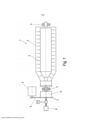
[0021] Figura 1 - uma vista anterior esquemática de uma centrífuga decantadora ou centrífuga de invólucro sólido;[0021] Figure 1 - a schematic front view of a decanter centrifuge or solid shell centrifuge;
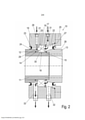
[0022] Figura 2 - uma vista anterior de uma primeira variante de um aparelho de resfriamento de mancal de rolamento de acordo com a invenção em corte;[0022] Figure 2 - a front view of a first variant of a roller bearing cooling apparatus according to the invention in section;
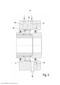
[0023] Figura 3 - uma vista anterior de uma segunda variante de um aparelho de resfriamento de mancal de rolamento de acordo com a invenção em corte;[0023] Figure 3 - a front view of a second variant of a roller bearing cooling apparatus according to the invention in section;
[0024] Figura 4 - uma vista anterior de uma terceira variante de um aparelho de resfriamento de mancal de rolamento de acordo com a invenção em corte.[0024] Figure 4 - a front view of a third variant of a roller bearing cooling apparatus according to the invention in section.
[0025] Na Figura 1 está representada esquematicamente uma vista dianteira de uma centrífuga decantadora ou centrífuga de invólucro sólido1 - abreviadamente designada a seguir como centrífuga. A centrífuga 1 apresenta um tambor 2 rotativo. O tambor 2 é montado rotativo por dois mancais de tambor 4. Os mancais de tambor 4 são executados de preferência como mancais de rolamento 30 (Figura 2). A centrífuga apresenta ainda uma rosca sem fim 3, que fica disposta coaxialmente no tambor 2. O tambor 2 é acionado por um motor de acionamento 5 por uma transmissão de meio de tração, que apresenta aqui por exemplo polias de correia 7 e correias de acionamento 8. A transmissão de meio de tração atua em uma outra transmissão 9, que aciona o tambor 4. A centrífuga apresenta de preferência ainda um outro motor de acionamento 6, que pela transmissão 9 serve ao acionamento da rosca sem fim 3 e produz um número de rotações diferente com relação ao tambor 2.[0025] In Figure 1 is schematically represented a front view of a decanter centrifuge or solid shell centrifuge1 - hereinafter referred to as centrifuge for short. The centrifuge 1 has a rotating drum 2. Drum 2 is rotatably mounted by two
[0026] Nas Figuras 2 a 4 estão representadas disposições de mancal com respectivamente um mancal de rolamento com variantes a título de exemplo e vantajosas de resfriamento a ar de mancal de rolamento 1 de acordo com a invenção. Como disposições de mancal de rolamento são viáveis especialmente também mancais de rolamento de duas fileiras ou dois mancais de rolamento lado a lado. Vêm ao caso ainda especialmente mancais esféricos estriados, mancais esféricos angulares e/ou mancais de rolos cilíndricos.[0026] In Figures 2 to 4 there are shown bearing arrangements with respectively a rolling bearing with variants by way of example and advantageous air-cooling of rolling bearing 1 according to the invention. In particular, double-row roller bearings or two side-by-side roller bearings are feasible as ball-bearing arrangements. Also relevant are splined spherical bearings, angular spherical bearings and/or cylindrical roller bearings.
[0027] O arranjo de mancal de rolamento do mancal de tambor 4 das Figuras 2, 3 e 4 apresenta um eixo oco 11, sobre o qual estão enfiados um anel 12 e um outro anel 13. Ambos os anéis 12, 13 são vedados com relação ao eixo oco 11 com vedações 14, 15. O anel 13 está fixado com elementos de fixação, como, por exemplo, parafusos (não representados) no eixo oco 11 em direção axial. Ambos os anéis 12, 13 formam respectivamente um ressalto de eixo 16, 17 e firmam axialmente um anel interno de mancal de rolamento 18 sobre o eixo oco 11. Os anéis 12, 14 se alargam, ademais, do mancal 4, aqui de preferência respectivamente conicamente, ou apresentam regiões cônicas. Os anéis 12, 13 encostam no mancal 4 em um raio situado mais internamente. Pelos segmentos cônicos é bem assegurado e de maneira construtivamente simples que o lubrificante possa fluir bem da abertura de saída da linha de fornecimento de lubrificante para o mancal e ali se distribuir.[0027] The roller bearing arrangement of the drum bearing 4 of Figures 2, 3 and 4 features a
[0028] Além disso, o arranjo de mancal de rolamento apresenta um alojamento 19. O alojamento 19 forma na região de um anel externo de mancal de rolamento 20 um ressalto de alojamento 21, em que está firmado axialmente com do lado do alojamento o anel externo de mancal de rolamento 20. Além disso, o alojamento 19 apresenta um anel de segurança 22 para alojamento, com que o anel externo de mancal de rolamento está igualmente axialmente fixado do lado do alojamento.[0028] Furthermore, the rolling bearing arrangement has a
[0029] O alojamento 19 apresenta, ainda, um ressalto 23, em que está inserida uma vedação 24. A vedação 24 se apoia do lado do eixo sobre o anel 12 e atua como vedação dinâmica, à semelhança de um anel de vedação de eixo radial.[0029] The
[0030] O arranjo de mancal de rolamento apresenta, além disso, uma tampa 25, que está fixada com elementos de fixação, como, por exemplo, parafusos (não representados) no alojamento 19 em direção axial. A tampa 25 apresenta uma vedação 26 do lado do alojamento. A tampa 25 apresenta, ainda, um ressalto 27, em que está inserida a vedação 26. A vedação 26 se apoia do lado do eixo sobre o anel 13 e funciona como vedação dinâmica, aqui um anel de vedação de eixo radial. São viáveis também outras disposições de vedação, por exemplo, anéis de vedação de eixo de ação dupla, vedações de anel corrediço ou dois ou mais anéis de vedação de eixo radial lado a lado.[0030] The rolling bearing arrangement also has a cover 25, which is fixed with fastening elements, such as screws (not shown) in the
[0031] O alojamento 19 apresenta, além disso, uma linha de fornecimento de lubrificante 28 em forma de uma perfuração com diâmetro se afilando em forma de bocal a jusante. A perfuração desemboca em um bocal 29, que se encontra no ressalto de alojamento 21, de modo que um fluxo de lubrificante conduzido pelo bocal 29 é conduzida entre anel interno de mancal de rolamento 18 e anel externo de rolamento 20 para dentro do mancal de rolamento 30. A saída da linha de fornecimento de lubrificante pode também ser alinhada apenas radialmente e/ou também inclinadamente (entre direção radial direção axial) ou apenas axialmente. Na Figura 2 a linha de fornecimento de lubrificante termina logo antes do segmento cônico do anel 12.[0031] The
[0032] Especialmente, de preferência é implementada uma lubrificação por circulação a óleo à maneira de um circuito. De preferência então, circulam 50l/h a 150l/h de lubrificante no circuito.[0032] In particular, oil circulation lubrication is preferably implemented in a circuit fashion. Preferably then, 50l/h to 150l/h of lubricant circulate in the circuit.
[0033] O lubrificante - de preferência óleo lubrificante - pode, contudo, por exemplo, também ser guiado para dentro do mancal de rolamento 30 pelo princípio de uma lubrificação de quantidade mínima em pequenos impulsos individuais (pelo princípio da em si conhecida lubrificação de quantidade mínima) pelo bocal 29 (ver a EP 2 435 189 B1). São então emitidas de preferência todas a cada 60 a 180 seg. quantidades de lubrificante entre 5 mm3 e 1000 mm3.[0033] The lubricant - preferably lubricating oil - can, however, for example also be guided into the
[0034] O alojamento 19 apresenta ainda um aparelho de resfriamento de mancal de rolamento. Ele apresenta, por sua vez, ao menos uma linha de fornecimento de ar de resfriamento 31. Aqui ele está disposto em direção da tampa 25 espaçada da linha de fornecimento de lubrificante 28 e desemboca aqui na região do anel de segurança 22 no espaço interno do alojamento 19. Pelas vedações 24 e 26 está vedada a região de alojamento, em que está disposto o mancal de rolamento 30, com relação ao ambiente circundante e pelas vedações 14, 15 com relação ao eixo oco 11. O lubrificante pode assim fluir pelo mancal de rolamento 30 e o mancal de rolamento 30 é lubrificado. O ar de resfriamento flui em torno do mancal de rolamento e resfria o mancal de rolamento ao passar e/ou fluir pelo mesmo.[0034]
[0035] O alojamento 19 apresenta, além disso, respectivamente uma linha de descarga de lubrificante 32 e uma linha de descarga de ar de resfriamento 33.[0035] The
[0036] A linha de fornecimento de lubrificante 28 está disposta espaçada da linha de fornecimento de ar de resfriamento 31 e defronte à linha de descarga de ar de resfriamento 33 e a linha de fornecimento de ar de resfriamento 31 defronte à linha de descarga de lubrificante 32 com relação ao mancal de rolamento 30. A linha de descarga de lubrificante 32 assenta no lado de alojamento voltado para a tampa, enquanto que a linha de descarga de ar de resfriamento 33 fica posicionado no lado de alojamento oposto à tampa.[0036] The
[0037] Pela disposição alternada de linha de fornecimento de lubrificante 28 e linha de descarga de lubrificante 32 ou de linha de fornecimento de ar de resfriamento 31 e linha de descarga de ar de resfriamento 33, tanto o fluxo de lubrificante como também o fluxo de ar de resfriamento são forçadas a fluir através do mancal de rolamento 30, de modo que calor é descarregado calor do anel interna de mancal de rolamento 18, do anel externo de mancal de rolamento 20 bem como das esferas de mancal de rolamento pelo fluxo de ar de resfriamento. O fluxo de ar de resfriamento atua, portanto, diretamente nos locais do mancal de rolamento 30, em que resulta calor por atrito.[0037] By the alternating arrangement of
[0038] É assim obtido um bom efeito de resfriamento especialmente pelo fluxo de ar de resfriamento. Para comprovação desse efeito foram realizados ensaios com um Dekanter CF 6000 da Depositante. O número de rotações do tambor se situou então em cerca de 35000 rpm. Com um fluxo de volume de ar de resfriamento de 10 m3 /h, que apresentava temperatura ambiente (cerca de 20°C - 25°C), foi possibilitada uma redução de temperatura do mancal de rolamento 30 com número de rotações operacional em 18 K e com uma corrente volumétrica de ar de resfriamento de 30 m3 /h uma redução de temperatura do mancal de rolamento 30 com número de rotações operacional em 23 K.[0038] A good cooling effect is thus obtained especially by the cooling air flow. To prove this effect, tests were carried out with a Dekanter CF 6000 from the Depositor. The speed of the drum was then around 35000 rpm. With a flow of cooling air volume of 10 m3 /h, which had ambient temperature (about 20°C - 25°C), a temperature reduction of the rolling
[0039] Particularmente vantajosa é a invenção devido a esse efeito quando de uma separação centrífuga de um centrifugado com uma temperatura elevada de, por exemplo, mais de 100° e/ou com temperaturas ambiente muito altas acima de 25°C. A temperatura de resfriamento se situa de preferência abaixo de 25°, especialmente abaixo de 15°. O ar de resfriamento apresenta, de preferência e vantajosamente, uma temperatura mais baixa do que a temperatura do centrifugado e/ou do ambiente circundante na centrífuga.[0039] The invention is particularly advantageous due to this effect when centrifugal separation from a centrifuge with a high temperature of, for example, more than 100° and/or with very high ambient temperatures above 25°C. The cooling temperature is preferably below 25°, especially below 15°. The cooling air preferably and advantageously has a lower temperature than the temperature of the centrifuge and/or the surrounding environment in the centrifuge.
[0040] Dessa redução de temperatura do mancal de rolamento 30 com número de rotações operacional resulta um correspondente aumento de vida útil ou um prolongamento do intervalo de manutenção do mancal de rolamento 30, pois o lubrificante resfriado pode ser empregado por mais tempo e então o mancal é poupado. Graças à temperatura mais baixa, é adicionalmente favoravelmente influenciada a viscosidade e se forma uma película lubrificante separadora, mais espessa, no mancal de rolamento, o que reduz o desgaste.[0040] This temperature reduction of the rolling
[0041] A disposição da Figura 2 é especialmente vantajosa, mas também são viáveis outras disposições de linha de fornecimento e descarga de ar de resfriamento e linha de fornecimento e descarga de lubrificante. Segundo a Figura 3, a linha de descarga de ar de resfriamento e a linha de descarga de lubrificante são executados como uma única linha integrada 34, de modo que a descarga do ar de resfriamento e do lubrificante ocorre em conjunto por essa linha 34. Essa variante é construtivamente de implementação particularmente simples. De preferência aí está pós-conectado à linha 34 um separador de óleo não representado, que pode ser executado ,por exemplo, como hidrociclone ou como filtro.[0041] The arrangement of Figure 2 is especially advantageous, but other arrangements of cooling air supply and discharge line and lubricant supply and discharge line are also feasible. According to Figure 3, the cooling air discharge line and the lubricant discharge line are executed as a single
[0042] Segundo a Figura 4 é ainda previsto que a linha de descarga de ar de resfriamento 33 fica disposta espaçada do mancal 4, sendo executado entre a linha de descarga de ar de resfriamento 33 e o mancal de preferência um ressalto/fenda anular 35, em que se coleta na operação quando de rotações lubrificante radialmente externo, que pode ser descarregado pela linha de descarga de lubrificante 32. Sua abertura de entrada 36 se situa, ademais, em um raio maior do que aquele da abertura de entrada 37 da linha de descarga de ar de resfriamento 33, de modo que quando de rotações o lubrificante fluente é descarregado pela linha de descarga de lubrificante 32. De maneira simples é assim impedido que o óleo possa fluir para dentro da linha de descarga de ar de resfriamento 33. Essa variante apresenta assim um separador de óleo integrado. Também seria viável dispor um disco se estendendo radialmente lateralmente no mancal, para impedir que lubrificante possa fluir para dentro da linha de descarga de ar de resfriamento (não representado).[0042] According to Figure 4, it is also provided that the cooling
[0043] Nas Figuras 3 e 4 se pode também verificar que a abertura de saída 38 da linha de fornecimento de lubrificante 28 se situa em um raio do alojamento 19 menor do que aquele da linha de fornecimento de ar de resfriamento 31. Ademais é vantajoso que a linha de lubrificante na região extrema 39 não se estenda exclusivamente radialmente, mas sim angularmente, de modo que o óleo lubrificante também pode ser conduzido com uma componente de velocidade axial para o mancal 4. Lista de referências 1 centrífuga decantadora ou centrífuga de invólucro sólido 2 tambor 3 rosca sem fim 4 mancal de tambor 5 motor de acionamento 6 motor de acionamento 7 polias 8 correias de acionamento 9 transmissão 10 resfriamento a ar de mancal de rolamento 11 eixo oco 12 anel 13 anel 14 vedação 15 vedação 16 ressalto de eixo 17 ressalto de eixo 18 anel interno do mancal de rolamento 19 alojamento 20 anel externo do mancal de rolamento 21 ressalto de alojamento 22 anel de segurança 23 ressalto 24 vedação 25 tampa 26 vedação 27 ressalto 28 linha de fornecimento de lubrificante 29 bocal 30 mancal de rolamento 31 linha de fornecimento de ar de resfriamento 32 linha de descarga de lubrificante 33 linha de descarga de ar de resfriamento 34 linha 35 fenda 36 abertura de entrada 37 abertura de entrada 38 abertura de saída 39 região extrema[0043] In Figures 3 and 4 it can also be seen that the outlet opening 38 of the
Claims (12)
Applications Claiming Priority (3)
| Application Number | Priority Date | Filing Date | Title |
|---|---|---|---|
| DE102013114510.8 | 2013-12-19 | ||
| DE102013114510.8A DE102013114510A1 (en) | 2013-12-19 | 2013-12-19 | Bearing arrangement for centrifuges |
| PCT/EP2014/076528 WO2015090994A1 (en) | 2013-12-19 | 2014-12-04 | Bearing arrangement for centrifuges |
Publications (2)
| Publication Number | Publication Date |
|---|---|
| BR112016012468A8 BR112016012468A8 (en) | 2020-05-05 |
| BR112016012468B1 true BR112016012468B1 (en) | 2022-01-25 |
Family
ID=52014079
Family Applications (1)
| Application Number | Title | Priority Date | Filing Date |
|---|---|---|---|
| BR112016012468-5A BR112016012468B1 (en) | 2013-12-19 | 2014-12-04 | BEARING ARRANGEMENT FOR CENTRIFUGES AND CENTRIFUGES |
Country Status (9)
| Country | Link |
|---|---|
| US (1) | US10639648B2 (en) |
| EP (1) | EP3084241B1 (en) |
| JP (1) | JP6647203B2 (en) |
| KR (1) | KR20160098369A (en) |
| CN (1) | CN105829749B (en) |
| BR (1) | BR112016012468B1 (en) |
| DE (1) | DE102013114510A1 (en) |
| UA (1) | UA118465C2 (en) |
| WO (1) | WO2015090994A1 (en) |
Families Citing this family (9)
| Publication number | Priority date | Publication date | Assignee | Title |
|---|---|---|---|---|
| DE102013114510A1 (en) * | 2013-12-19 | 2015-06-25 | Gea Mechanical Equipment Gmbh | Bearing arrangement for centrifuges |
| CN107763074B (en) * | 2017-11-17 | 2020-07-03 | 洛阳轴承研究所有限公司 | Self-lubricating rolling bearing |
| CN109798302B (en) * | 2017-11-17 | 2021-01-22 | 洛阳轴承研究所有限公司 | Rolling bearing and lubricating method thereof, lubricating spacer ring and spacer ring assembly |
| CN107725606B (en) * | 2017-11-17 | 2020-09-04 | 洛阳轴承研究所有限公司 | Rolling bearing and rotating ring thereof |
| JP6810020B2 (en) * | 2017-12-19 | 2021-01-06 | 巴工業株式会社 | Disc centrifuge |
| EP3871791A1 (en) * | 2020-02-25 | 2021-09-01 | Alfa Laval Corporate AB | Method for determining if air is trapped within a centrifugal separator |
| TWI830130B (en) * | 2021-02-25 | 2024-01-21 | 日商發那科股份有限公司 | Machinery with lubrication chamber |
| DE102021113425A1 (en) | 2021-05-25 | 2022-12-01 | Gea Westfalia Separator Group Gmbh | Solid bowl centrifuge |
| KR102616210B1 (en) * | 2022-07-08 | 2023-12-19 | 김은수 | Dehydrated cake moisture content control type centrifugal concentration dehydrator |
Family Cites Families (47)
| Publication number | Priority date | Publication date | Assignee | Title |
|---|---|---|---|---|
| US1093480A (en) * | 1912-06-13 | 1914-04-14 | Thomas And Sons Company R | Insulator. |
| US1598393A (en) * | 1921-11-14 | 1926-08-31 | Montgomery Ward & Co Inc | Electrical drive for cream separators |
| US1745853A (en) * | 1926-10-16 | 1930-02-04 | Hubert J M C Krantz | Oiling system for centrifugal machines |
| US2398944A (en) * | 1942-07-21 | 1946-04-23 | Blaw Knox Co | Lubricated shaft bearing |
| US3042462A (en) * | 1959-05-27 | 1962-07-03 | Snecma | Arrangement for lubricating and cooling rotating parts |
| DE1147447B (en) | 1959-05-27 | 1963-04-18 | Snecma | Device for the lubrication and cooling of rolling bearings, gear wheels working at high temperature and at high speed. |
| US3163104A (en) * | 1960-06-21 | 1964-12-29 | Plasticmaster Corp | Method and means for continuous plastic lamination |
| GB1050046A (en) * | 1964-05-04 | |||
| US3315882A (en) * | 1964-10-05 | 1967-04-25 | Pennsalt Chemicals Corp | Centrifuge having rotary solids discharge conveyor with bearing seal |
| US3318644A (en) * | 1965-02-24 | 1967-05-09 | Gen Motors Corp | Centrifugal bearing lubrication system |
| FR1488911A (en) * | 1965-08-17 | |||
| US3428247A (en) * | 1967-09-26 | 1969-02-18 | Combustion Eng | Centrifuge lubricating and seal system |
| US3604769A (en) | 1968-09-23 | 1971-09-14 | Cryogenic Technology Inc | Temperature-controlled spindle for centrifuges and similar apparatus |
| US3604617A (en) * | 1969-04-09 | 1971-09-14 | Beckman Instruments Inc | Ultracentrifuge transmission assembly |
| US3767013A (en) * | 1971-08-16 | 1973-10-23 | Pennwalt Corp | Start-up lubricator |
| US3729128A (en) * | 1971-09-23 | 1973-04-24 | Pennwalt Corp | High pressure centrifuge lubrication system |
| JPS49143069U (en) * | 1973-04-06 | 1974-12-10 | ||
| US4205779A (en) * | 1979-03-14 | 1980-06-03 | Beckman Instruments, Inc. | Pressure bypass ports for an ultracentrifuge drive system in a vacuum environment |
| US4322030A (en) * | 1979-03-14 | 1982-03-30 | Beckman Instruments, Inc. | Lubrication and cooling system for a high speed ultracentrifuge drive assembly |
| US4226359A (en) * | 1979-03-14 | 1980-10-07 | Beckman Instruments, Inc. | Direct drive high speed ultracentrifuge |
| US4527661A (en) * | 1981-10-29 | 1985-07-09 | Kearney & Trecker Corporation | Adaptive control system for machine tool or the like |
| SE445665B (en) * | 1984-11-28 | 1986-07-07 | Alfa Laval Separation Ab | Centrifugal Separator with a Hole Sealed by a Mechanical Seal |
| SU1704839A1 (en) * | 1988-07-18 | 1992-01-15 | Московское научно-производственное объединение "Биофизприбор" | Ultracentrifuge drive |
| US5051007A (en) * | 1989-10-02 | 1991-09-24 | National-Oilwell | Lubrication of a centrifugal pump bearing |
| JPH0722721B2 (en) * | 1990-05-10 | 1995-03-15 | 日本ピラー工業株式会社 | Lubricating cooling device for high-speed drive mechanism |
| EP0458499B1 (en) * | 1990-05-21 | 1997-07-23 | Makino Milling Machine Co. Ltd. | Apparatus for cooling a spindle bearing of a machine |
| SE510204C2 (en) * | 1997-06-16 | 1999-05-03 | Alfa Laval Ab | Apparatus and means for cooling a bearing |
| SE9702290D0 (en) * | 1997-06-16 | 1997-06-16 | Alfa Laval Ab | Sealing device for a centrifugal separator |
| SE509516C2 (en) * | 1997-06-16 | 1999-02-08 | Alfa Laval Ab | Apparatus for supplying a liquid at a bearing to a rotating shaft |
| DE10212808B4 (en) * | 2002-03-22 | 2004-07-29 | Westfalia Separator Ag | separator |
| JP4151472B2 (en) * | 2003-04-25 | 2008-09-17 | 株式会社ジェイテクト | Roller bearing device and lubrication method for roller bearing |
| BE1015913A3 (en) * | 2004-02-23 | 2005-11-08 | Atlas Copco Airpower Nv | Machine with improved bearing lubrication. |
| ES2426353T3 (en) * | 2004-03-22 | 2013-10-22 | Paul Müller GmbH & Co. KG Unternehmensbeteiligungen | Spindle for a machine tool with a bearing element with a capillary feed line for lubricant feed |
| JP2006046454A (en) * | 2004-08-03 | 2006-02-16 | Nsk Ltd | Bearing device and spindle device, and machine tool |
| JP2007024256A (en) * | 2005-07-20 | 2007-02-01 | Ntn Corp | Lubricating device of rolling bearing |
| US8025443B2 (en) * | 2005-08-31 | 2011-09-27 | Alfa Laval Corporate Ab | Bearing device |
| JP4993688B2 (en) * | 2006-11-15 | 2012-08-08 | オークマ株式会社 | Spindle lubricator |
| US8287441B2 (en) * | 2007-03-23 | 2012-10-16 | Wick Rod | Apparatus and methods for remediating drill cuttings and other particulate materials |
| DE102008015134A1 (en) * | 2008-03-20 | 2009-10-01 | Gea Westfalia Separator Gmbh | Gear arrangement for a centrifuge |
| JP2009150559A (en) * | 2009-04-10 | 2009-07-09 | Ntn Corp | Lubricating device of rolling bearing |
| DE102009022972A1 (en) | 2009-05-28 | 2010-12-02 | Gea Westfalia Separator Gmbh | Centrifuge with a lubricant system |
| JP5260798B2 (en) * | 2010-08-17 | 2013-08-14 | 巴工業株式会社 | Decanter centrifuge with continuous greasing device |
| EP2910806B1 (en) * | 2012-09-24 | 2021-05-19 | NTN Corporation | Bearing device with a cooling structure |
| JP5547331B1 (en) * | 2013-11-04 | 2014-07-09 | 巴工業株式会社 | Centrifuge |
| DE102013114510A1 (en) * | 2013-12-19 | 2015-06-25 | Gea Mechanical Equipment Gmbh | Bearing arrangement for centrifuges |
| EP3124812B1 (en) * | 2014-03-22 | 2019-02-20 | NTN Corporation | Cooling structure for bearing device |
| DE102015118599B4 (en) * | 2015-10-30 | 2020-01-30 | Flottweg Se | bearing arrangement |
-
2013
- 2013-12-19 DE DE102013114510.8A patent/DE102013114510A1/en not_active Withdrawn
-
2014
- 2014-12-04 KR KR1020167018731A patent/KR20160098369A/en not_active Application Discontinuation
- 2014-12-04 CN CN201480068960.XA patent/CN105829749B/en active Active
- 2014-12-04 WO PCT/EP2014/076528 patent/WO2015090994A1/en active Application Filing
- 2014-12-04 UA UAA201607791A patent/UA118465C2/en unknown
- 2014-12-04 EP EP14808964.2A patent/EP3084241B1/en active Active
- 2014-12-04 US US15/103,011 patent/US10639648B2/en active Active
- 2014-12-04 JP JP2016541053A patent/JP6647203B2/en active Active
- 2014-12-04 BR BR112016012468-5A patent/BR112016012468B1/en active IP Right Grant
Also Published As
| Publication number | Publication date |
|---|---|
| US10639648B2 (en) | 2020-05-05 |
| KR20160098369A (en) | 2016-08-18 |
| CN105829749A (en) | 2016-08-03 |
| CN105829749B (en) | 2018-09-14 |
| JP6647203B2 (en) | 2020-02-14 |
| US20160310969A1 (en) | 2016-10-27 |
| DE102013114510A1 (en) | 2015-06-25 |
| UA118465C2 (en) | 2019-01-25 |
| WO2015090994A1 (en) | 2015-06-25 |
| JP2016540640A (en) | 2016-12-28 |
| BR112016012468A8 (en) | 2020-05-05 |
| EP3084241B1 (en) | 2018-04-11 |
| EP3084241A1 (en) | 2016-10-26 |
Similar Documents
| Publication | Publication Date | Title |
|---|---|---|
| BR112016012468B1 (en) | BEARING ARRANGEMENT FOR CENTRIFUGES AND CENTRIFUGES | |
| CN102466026B (en) | Shaft device | |
| CN103079708B (en) | Decanter centrifuge provided with continuous greasing device | |
| RU2660911C2 (en) | Device for lubrication of electric motor rolling bearing | |
| US20110158803A1 (en) | Bearing arrangement having a double-row roller bearing, turbocharger and method for feeding a lubricant to the rows of rolling bodies of a double-row roller bearing | |
| US10364881B2 (en) | Turbine engine module comprising a casing around a device with a cover for recovering lubricating oil | |
| BR112012024525B1 (en) | COMBUSTION ENGINE | |
| US20150097073A1 (en) | Self Scavenging Gear Shield | |
| KR101836691B1 (en) | Lubricating apparatus of differential for vehicle | |
| GB2552883A (en) | Device for recovering lubrication oil ejected by centrifugal effect in a turbine engine | |
| US8444542B2 (en) | Gear apparatus for a centrifuge including a drive shaft having two hollow longitudinal channels for lubricating the gear apparatus via an associated lubricant compensating system | |
| EP2868386A1 (en) | Centrifugal separator | |
| BRPI1012887B1 (en) | CENTRIFUGAL SEPARATOR | |
| CN106461088B (en) | Improve the mechanical rotary seal device of gas separation | |
| US20170276176A1 (en) | Bearing apparatus and pump | |
| CN110402216B (en) | Transmission device, in particular for a drive train of a rail vehicle | |
| JP6221161B2 (en) | Internal combustion engine having a two-stage separated blowby gas recirculation system | |
| CN114286888B (en) | Device for distributing oil from a rolling bearing for an aircraft turbine engine | |
| JP6131656B2 (en) | Water pump | |
| US8419287B2 (en) | Axle bearing lubricating and cooling system | |
| US1685517A (en) | Bearing mounting | |
| CN106762790B (en) | Fan transmission device for cooling automobile engine | |
| RU2667753C1 (en) | Grinding device | |
| JP2008046064A (en) | Rotation testing device of rolling bearing | |
| CN210799364U (en) | Compressor and air conditioning unit |
Legal Events
| Date | Code | Title | Description |
|---|---|---|---|
| B06U | Preliminary requirement: requests with searches performed by other patent offices: procedure suspended [chapter 6.21 patent gazette] | ||
| B09A | Decision: intention to grant [chapter 9.1 patent gazette] | ||
| B16A | Patent or certificate of addition of invention granted [chapter 16.1 patent gazette] |
Free format text: PRAZO DE VALIDADE: 20 (VINTE) ANOS CONTADOS A PARTIR DE 04/12/2014, OBSERVADAS AS CONDICOES LEGAIS. |