BR112016012169B1 - METHOD FOR TREATMENT OF CONTINUOUS LEAF MATERIAL, APPARATUS FOR TREATMENT OF CONTINUOUS LEAF MATERIAL, INSTALLATION AND USE - Google Patents
METHOD FOR TREATMENT OF CONTINUOUS LEAF MATERIAL, APPARATUS FOR TREATMENT OF CONTINUOUS LEAF MATERIAL, INSTALLATION AND USE Download PDFInfo
- Publication number
- BR112016012169B1 BR112016012169B1 BR112016012169-4A BR112016012169A BR112016012169B1 BR 112016012169 B1 BR112016012169 B1 BR 112016012169B1 BR 112016012169 A BR112016012169 A BR 112016012169A BR 112016012169 B1 BR112016012169 B1 BR 112016012169B1
- Authority
- BR
- Brazil
- Prior art keywords
- roller
- wave
- web material
- sheet material
- beams
- Prior art date
Links
- 239000000463 material Substances 0.000 title claims abstract description 242
- 238000009434 installation Methods 0.000 title claims description 3
- 238000002788 crimping Methods 0.000 claims abstract description 21
- 238000004519 manufacturing process Methods 0.000 claims abstract description 19
- 230000000391 smoking Effects 0.000 claims description 10
- 239000004033 plastic Substances 0.000 claims description 8
- 229920003023 plastic Polymers 0.000 claims description 8
- 238000011144 upstream manufacturing Methods 0.000 claims description 8
- 238000006073 displacement reaction Methods 0.000 claims description 4
- 229920002301 Cellulose acetate Polymers 0.000 claims description 3
- 235000019504 cigarettes Nutrition 0.000 claims description 2
- 239000007787 solid Substances 0.000 abstract 1
- 230000000875 corresponding Effects 0.000 description 7
- 239000004626 polylactic acid Substances 0.000 description 6
- 229920000747 poly(lactic acid) polymer Polymers 0.000 description 5
- 238000000034 method Methods 0.000 description 4
- 241000208125 Nicotiana Species 0.000 description 3
- 235000002637 Nicotiana tabacum Nutrition 0.000 description 3
- 238000005452 bending Methods 0.000 description 3
- 230000002349 favourable Effects 0.000 description 3
- 239000012467 final product Substances 0.000 description 3
- 210000001699 lower leg Anatomy 0.000 description 3
- 230000001808 coupling Effects 0.000 description 2
- 238000010168 coupling process Methods 0.000 description 2
- 238000005859 coupling reaction Methods 0.000 description 2
- 239000000123 paper Substances 0.000 description 2
- 239000000047 product Substances 0.000 description 2
- 239000000443 aerosol Substances 0.000 description 1
- 230000006399 behavior Effects 0.000 description 1
- 229920001222 biopolymer Polymers 0.000 description 1
- 230000015572 biosynthetic process Effects 0.000 description 1
- 239000011111 cardboard Substances 0.000 description 1
- 229920002678 cellulose Polymers 0.000 description 1
- 239000001913 cellulose Substances 0.000 description 1
- 238000007906 compression Methods 0.000 description 1
- 238000005520 cutting process Methods 0.000 description 1
- 238000009826 distribution Methods 0.000 description 1
- 230000000694 effects Effects 0.000 description 1
- -1 for example Substances 0.000 description 1
- 238000005755 formation reaction Methods 0.000 description 1
- 230000001771 impaired Effects 0.000 description 1
- 230000001788 irregular Effects 0.000 description 1
- 239000002184 metal Substances 0.000 description 1
- 239000000203 mixture Substances 0.000 description 1
- 238000003825 pressing Methods 0.000 description 1
- 230000001360 synchronised Effects 0.000 description 1
Images
Abstract
MÉTODO E APARELHO PARA TRATAMENTO DE MATERIAL DE FOLHA CONTÍNUA. A presente invenção refere-se ao método para o tratamento de material de folha contínua para uso na fabricação de artigos em forma de coluna que compreende as etapas de fornecer um material de folha contínua que compreende uma estrutura de friso que se desloca na direção longitudinal do material de folha contínua. Compreende ainda a etapa de fornecer um primeiro rolo e um segundo rolo, o primeiro rolo e o segundo rolo compreendem uma pluralidade de cames que se deslocam circunferencialmente, os cames que se deslocam circunferencialmente do primeiro rolo e os cames que se deslocam circunferencialmente do segundo rolo se acoplam entre si. O método compreende ainda uma etapa de orientação do material de folha contínua que compreende a estrutura de friso entre os cames que se deslocam circunferencialmente do primeiro rolo e do segundo rolo. Desse modo, o material de folha contínua que compreende a estrutura de friso é fornecido com uma estrutura tipo onda, a estrutura tipo onda se desloca na direção longitudinal do material de folha contínua e se sobrepõe à estrutura de friso.METHOD AND APPARATUS FOR TREATMENT OF CONTINUOUS SHEET MATERIAL. The present invention relates to a method for treating web material for use in the manufacture of column-shaped articles comprising the steps of providing a web material comprising a crimp structure moving in the longitudinal direction of the solid sheet material. It further comprises the step of providing a first roller and a second roller, the first roller and the second roller comprising a plurality of circumferentially moving cams, the circumferentially moving cams of the first roller and the circumferentially moving cams of the second roller couple with each other. The method further comprises a step of orienting the web material comprising the crimping structure between the circumferentially moving cams of the first roller and the second roller. Thereby, the web material comprising the crimp structure is provided with a wave-like structure, the wave-like structure moves in the longitudinal direction of the web material and overlaps the crimp structure.
Description
[0001] A presente invenção se refere aos métodos e aparelhos pa ra tratamento de material de folha contínua. Especialmente, está relacionado com o tratamento de material de folha contínua para uso na fabricação de artigos em forma de haste (“rod”), por exemplo, os elementos de filtro para artigos para fumar.[0001] The present invention relates to methods and apparatus for treating web material. Especially, it relates to the treatment of web material for use in the manufacture of rod-shaped articles, for example filter elements for smoking articles.
[0002] Para a fabricação de elementos de filtro, geralmente um material de folha contínua plana é empurrado em uma haste em formato circular, em que haste pode então ser elementos de filtro individuais. Estes elementos de filtro em forma de haste tem uma estrutura interna de ordem essencialmente aleatória. No entanto, o material do elemento de filtro e especialmente sua disposição no elemento de filtro pode influenciar a qualidade do filtro e sua reprodutibilidade.[0002] For the fabrication of filter elements, generally a flat web material is pushed onto a circular shaped rod, on which rod can then be individual filter elements. These rod-shaped filter elements have an internal structure of essentially random order. However, the material of the filter element and especially its arrangement on the filter element can influence the quality of the filter and its reproducibility.
[0003] Existe uma necessidade de um método e aparelho para o tratamento de material de folha para uso na fabricação de artigos em forma de haste, que levam em conta as desvantagens dos métodos do estado da técnica. Especialmente, há uma necessidade de tais métodos e aparelhos que permitem a produção de elementos de filtro para artigos para fumar com uma boa reprodutibilidade.[0003] There is a need for a method and apparatus for treating sheet material for use in the manufacture of rod-shaped articles, which take into account the disadvantages of prior art methods. Especially, there is a need for such methods and apparatus which enable the production of filter elements for smoking articles with good reproducibility.
[0004] De acordo com um aspecto da invenção, um método para o tratamento de material de folha contínua para uso na fabricação de artigos em forma de haste é fornecido como, por exemplo, os elementos de filtro para artigos para fumar. O método compreende a etapa de fornecer um material de folha contínua que compreende uma estrutura de friso, a estrutura de friso se desloca na direção longitudinal do material de folha contínua. Este compreende ainda a etapa de fornecimento de um primeiro rolo e de um segundo rolo. O primeiro rolo e o segundo rolo compõem uma pluralidade de cames que se deslocam circunferencialmente. Os cames que se deslocam circunferencialmen- te do primeiro rolo e os cames que se deslocam circunferencialmente do segundo rolo se acoplam entre si. Uma etapa adicional compreende guiar o material de folha contínua que compreende a estrutura de friso entre os cames que se deslocam circunferencialmente do primeiro rolo e do segundo rolo. Desse modo, o material de folha contínua que compreende a estrutura de friso que se desloca na direção longitudinal é fornecido com uma estrutura tipo onda que se desloca na direção longitudinal do material de folha contínua e se sobrepõe à estrutura de friso. Devido à estrutura tipo onda ser disposta na direção lon-gitudinal do material de folha contínua (a direção longitudinal também correspondente a uma direção de transporte do material de folha contínua), o material de folha que compreende a estrutura de friso e que compreende a estrutura tipo onda pode, então, ser dobrado ou comprimido na direção transversal do material de folha (ou direção transversal a uma direção de transporte do material de folha), de acordo com a estrutura tipo onda. A estrutura tipo onda define a maneira como o material de folha dobra ao ser comprimido. A estrutura tipo onda sobreposta tem dimensões em uma direção perpendicular a um plano atravessando o material de folha em que as dimensões são, pelo menos nesta direção perpendicular, maiores do que as dimensões da estrutura de friso na referida direção perpendicular.[0004] According to one aspect of the invention, a method for treating web material for use in the manufacture of rod-shaped articles is provided such as, for example, filter elements for smoking articles. The method comprises the step of providing a web material comprising a crimp structure, the crimp structure moving in the longitudinal direction of the web material. This further comprises the step of providing a first roll and a second roll. The first roller and the second roller comprise a plurality of circumferentially moving cams. The circumferentially moving cams of the first roller and the circumferentially moving cams of the second roller couple together. A further step comprises guiding the web material comprising the crimping structure between the circumferentially moving cams of the first roller and the second roller. Thereby, the web material comprising the longitudinally moving crimp structure is provided with a wave-like structure that moves in the longitudinal direction of the web material and overlaps the crimp structure. Because the wave-like structure is arranged in the longitudinal direction of the web material (the longitudinal direction also corresponding to a transport direction of the web material), the web material comprising the crimp structure and comprising the structure The wave-like type can then be bent or compressed in the transverse direction of the sheet material (or direction transverse to a conveying direction of the sheet material), according to the wave-like structure. The wave-like structure defines how the sheet material bends when compressed. The superimposed wave-like structure has dimensions in a direction perpendicular to a plane traversing the sheet material where the dimensions are, at least in this perpendicular direction, greater than the dimensions of the crimp structure in said perpendicular direction.
[0005] Ao executar o método de tratamento, o material de folha contínua é guiado entre o primeiro e o segundo rolo e, portanto, entre os cames que se deslocam circunferencialmente do primeiro e do segundo rolo. Os cames acoplados forçam o material de folha contínua em uma forma tipo ondas que é definida pelos cames quando o material de folha passa entre os dois rolos. Desse modo, a estrutura tipo onda é imposta e criada no material de folha contínua, em que a estru- tura tipo onda se sobrepõe à estrutura de friso já presente no material de folha. Após fornecer o material de folha com a estrutura tipo onda, o material de folha já é dobrado em certa medida ao longo da largura do material de folha. Quando está sendo dobrado adicionalmente, o material de folha segue a estrutura tipo onda e é tem a largura reduzida ainda mais ao ser comprimido na direção transversal. O material de folha é comprimido em uma forma final, por exemplo, circular. A alea- toriedade ocorre quando a dobradura do material de folha frisada em forma tipo haste pode ser, pelo menos em parte, substituída por uma estrutura predefinida e organizada, fornecida pela estrutura tipo onda. Uma estrutura bem definida representa uma especificação consistente ou a qualidade do artigo então produzido, por exemplo, uma resistênciaà tragada constante no comprimento de um elemento de filtro. Além disso, a criação de uma estrutura bem definida no elemento de filtro também permite uma alta reprodutibilidade dos elementos de filtro com especificações iguais. Isto é especialmente favorável para a fabricação de elementos de filtro curto. Em elementos de filtro curto, as estruturas irregulares podem ter um efeito mais proeminente em uma especificação de filtro do que em elementos de filtro longo, onde as irregularidades podem ser compensadas pelo menos até certa medida. O dobramento do material de folha, além disso, é suportado pela estrutura de friso. A estrutura de friso, que é também disposta na direção lon-gitudinal, facilita a dobradura ou a compressão do material de folha transversal no sentido longitudinal do material de folha. Além disso, a estrutura de friso suporta a criação de canais longitudinais entre as dobras do material de folha e ao longo do material de folha dobrada. Assim, com a estrutura de friso basicamente seguindo a estrutura tipo onda, a fabricação de produtos que podem ser reproduzidos é suportada.[0005] When carrying out the treatment method, the web material is guided between the first and second roller and therefore between the circumferentially moving cams of the first and second roller. The coupled cams force the web material into a wave-like shape that is defined by the cams as the web material passes between the two rollers. In this way, the wave-like structure is imposed and created on the web material, where the wave-like structure overlaps the crimp structure already present in the sheet material. After providing the sheet material with the wave-like structure, the sheet material is already folded to some extent along the width of the sheet material. When being further folded, the sheet material follows the wave-like structure and is further reduced in width by being compressed in the transverse direction. The sheet material is compressed into a final shape, eg circular. Randomness occurs when the folding of the crimped sheet material into a rod-like shape can be, at least in part, replaced by a pre-defined and organized structure provided by the wave-like structure. A well-defined structure represents a consistent specification or quality of the article then produced, for example a constant drag resistance over the length of a filter element. Furthermore, creating a well-defined structure in the filter element also allows for high reproducibility of filter elements with equal specifications. This is especially favorable for manufacturing short filter elements. In short filter elements, irregular structures can have a more prominent effect on a filter specification than in long filter elements, where irregularities can be compensated for at least to some extent. Folding of the sheet material is further supported by the crimp structure. The crimp structure, which is also disposed in the longitudinal direction, facilitates the folding or pressing of the transverse sheet material in the longitudinal direction of the sheet material. In addition, the crimp structure supports the creation of longitudinal channels between the plies of the sheet material and along the folded sheet material. So, with the crimp structure basically following the wave-like structure, the manufacture of reproducible products is supported.
[0006] Os dois rolos fornecidos com os cames atuam sobre o ma terial de folha de maneira localizada. Os cames dos rolos essencialmente atuam ao longo de somente uma linha, em que a linha se estende em toda a largura do material de folha. Por isso, em cima de estruturação do material de folha, a tensão no material pode ser mantida a um mínimo - temporalmente e localmente. Portanto, os materiais frágeis, por exemplo, com uma baixa resistência à tração, também po-dem ser fornecidos com uma estrutura sobreposta. Isto permite o uso de uma grande variedade de materiais para a produção de elementos em forma de haste, tendo uma estrutura de ordem elevada. Além disso, devido ao tempo curto e pequeno contato dos cames com o material de folha mediante a estruturação do material de folha, e devido ao fato de que os cames são rolados enquanto o material de folha passa entre os rolos, uma carga eletrostática do material ou um aquecimento acima do material de folha passando entre os rolos pode ser mantido a um mínimo. O fornecimento de um material de folha contínua com uma estrutura tipo onda para um comportamento de dobradura mais controlado pode ser favorável ao dobrar qualquer tipo de material de folha. No entanto, é especialmente favorável se material plástico ou um material que não mantenha facilmente a sua posição quando dobrado for trazido em forma de haste.[0006] The two rollers supplied with the cams act on the sheet material in a localized manner. The roller cams essentially act along only one line, where the line extends the entire width of the sheet material. Therefore, on top of structuring the sheet material, the tension in the material can be kept to a minimum – temporally and locally. Therefore, brittle materials, for example with a low tensile strength, can also be provided with a superimposed structure. This allows the use of a wide variety of materials to produce rod-shaped elements having a high order structure. Furthermore, due to the short time and small contact of the cams with the sheet material upon structuring of the sheet material, and due to the fact that the cams are rolled while the sheet material passes between the rollers, an electrostatic charge of the material or a heat up of the sheet material passing between the rolls can be kept to a minimum. Providing a web material with a wave-like structure for more controlled folding behavior can be beneficial when folding any type of sheet material. However, it is especially favorable if plastic material or a material that does not easily hold its position when folded is brought in in rod form.
[0007] De preferência, o material de folha é uma folha feita de um material plástico, por exemplo, um material de folha composto ou compreendendo um biopolímero como ácido polilático (PLA) ou um material de folha compreendendo um material com base em celulose, por exemplo, papel ou um material contendo tabaco, por exemplo, uma folha de tabaco. Como alternativa, o material de folha pode ser uma folha metálica ou ter estruturas em camada, como laminados, compreendendo duas ou mais camadas selecionadas dentre, por exemplo, papel, papelão, plástico ou metal.[0007] Preferably, the sheet material is a sheet made of a plastic material, for example a sheet material composed or comprising a biopolymer such as polylactic acid (PLA) or a sheet material comprising a material based on cellulose, for example, paper or a tobacco-containing material, for example a tobacco sheet. Alternatively, the sheet material can be a metallic sheet or have layered structures, such as laminates, comprising two or more layers selected from, for example, paper, cardboard, plastic or metal.
[0008] A estrutura tipo onda é sempre deslocada na direção longi tudinal do material de folha contínua para permitir o dobramento do material de folha em uma direção transversal do material de folha contínua. Desta forma, uma estrutura tipo onda pode se deslocar em uma direção longitudinal exata, mas também em direções longitudinais que variam ligeiramente da direção longitudinal exata, mas continua a ser uma estrutura tipo onda sobreposta de acordo com a invenção.[0008] The wave-like structure is always shifted in the longitudinal direction of the web material to allow the bending of the sheet material in a transverse direction of the web material. In this way a wave-like structure can travel in an exact longitudinal direction, but also in longitudinal directions which vary slightly from the exact longitudinal direction, but it remains an overlapping wave-like structure according to the invention.
[0009] Uma estrutura de friso pode ser fornecida no material de fo lha para se deslocar em uma direção longitudinal exata, mas também em direções longitudinais variando ligeiramente da direção longitudinal exata. Uma estrutura de friso também pode ser disposta exatamente em paralelo a estrutura tipo onda sobreposta ou pode variar ligeiramente da mesma direção exata da estrutura tipo onda. De preferência, as estruturas de friso têm dimensões em, pelo menos, uma direção perpendicular para um plano que se expande pelo material de folha, em que são menores do que a estrutura tipo onda nesta direção perpendicular. De preferência, as dimensões da estrutura de friso perpendicular ao plano de movimento do material de folha está na faixa abaixo de cerca de 0,5 mm, mais de preferência abaixo de 0,3 mm, por exemplo, 0,2 mm. De preferência, as dimensões laterais da estrutura de friso, ou seja, as distâncias entre os frisos individuais no material de folha varia entre abaixo de cerca de 0,5 milímetros, mais de preferência abaixo de 0,3 mm, por exemplo, 0,2 mm. De preferência, uma estrutura de friso é uma estrutura regular, por exemplo, uma estrutura de corrugados substancialmente paralelos.[0009] A crimp structure can be provided in the sheet material to travel in an exact longitudinal direction, but also in longitudinal directions varying slightly from the exact longitudinal direction. A crimp structure can also be arranged exactly parallel to the superimposed wave-like structure, or it can vary slightly from the exact same direction as the wave-like structure. Preferably, the crimp structures have dimensions in at least one direction perpendicular to a plane that expands through the sheet material, where they are smaller than the wave-like structure in this perpendicular direction. Preferably, the dimensions of the crimp structure perpendicular to the plane of movement of the sheet material is in the range below about 0.5mm, more preferably below 0.3mm, for example 0.2mm. Preferably, the lateral dimensions of the crimp structure, i.e. the distances between the individual crimps in the sheet material range from below about 0.5mm, more preferably below about 0.3mm, e.g. 2 mm. Preferably, a crimp structure is a regular structure, for example a structure of substantially parallel corrugations.
[0010] De acordo com um aspecto do método conforme esta in venção, fornecer o material de folha contínua compreendendo a estrutura de friso com uma estrutura tipo onda compreende fornecer o material de folha contínua com uma estrutura tipo onda tendo as dimensões de pico de onda até a calha de onda, ou a altura, na faixa de entre cerca de 10 mm e cerca de 50 mm, de preferência entre cerca de 15 mm e cerca de 35 mm. De preferência, a estrutura tipo onda descreve um caminho sinusoidal. De preferência, o caminho sinusoidal - ou de outra forma - em um aparelho de friso tem um comprimento correspondente à largura inicial do material de folha a ser fornecido com a estrutura tipo onda. De preferência, um comprimento de onda da estrutura tipo onda (distância de pico a pico) está na faixa de cerca de 5 mm a cerca de 40 mm, de preferência entre cerca de 10 mm e cerca de 25 mm.[0010] According to an aspect of the method in accordance with this invention, providing the web material comprising the crimp structure with a wave-like structure comprises providing the web material with a wave-like structure having the dimensions of a wave peak to the wave trough, or height, in the range of between about 10 mm and about 50 mm, preferably between about 15 mm and about 35 mm. Preferably, the wave-like structure describes a sinusoidal path. Preferably, the sinusoidal path - or otherwise - in a crimping apparatus has a length corresponding to the initial width of the sheet material to be provided with the wave-like structure. Preferably, a wavelength of the wave-like structure (peak-to-peak distance) is in the range of about 5 mm to about 40 mm, preferably between about 10 mm and about 25 mm.
[0011] De preferência, uma distância de pico a pico é medida do centro ao centro dos picos ou a partir do ponto mais alto ao ponto mais alto dos picos. De preferência, uma distância de calha a calha é medida do centro ao centro das calhas ou do ponto mais profundo ao ponto mais profundo das calhas.[0011] Preferably, a peak-to-peak distance is measured from the center to the center of the peaks or from the highest point to the highest point of the peaks. Preferably, a runner to runner distance is measured from the center to the center of the runners or from the deepest point to the deepest point of the runners.
[0012] De acordo com um outro aspecto do método de acordo com a invenção, o método compreende a etapa de fornecer o material de folha contínua, compreendendo a estrutura de friso com uma estrutura tipo onda, em que a estrutura tipo onda compreende uma ondulação de uma ordem mais elevada possível de forma que o referido material de folha compreende a estrutura tipo onda que compreende a estrutura de friso e compreende a referida estrutura tipo onda após comprimir conforme a estrutura tipo onda sobreposta se encaixa em um círculo, por exemplo, na entrada de um jato de ar ou de uma acessório de lin- gueta, em que o círculo de entrada tem uma seção transversal em uma faixa de cerca de 10 mm a cerca de 60 mm, de preferência em uma faixa de entre cerca de 5 mm a cerca de 45 mm.[0012] According to another aspect of the method according to the invention, the method comprises the step of providing the web material, comprising the crimp structure with a wave-like structure, wherein the wave-like structure comprises a corrugation of a higher order possible so that said sheet material comprises the wave-like structure comprising the crimp structure and comprises said wave-like structure after compressing as the superimposed wave-like structure fits into a circle, e.g. inlet of an air jet or a tongue fitting, wherein the inlet circle has a cross section in a range of about 10 mm to about 60 mm, preferably in a range of between about 5 mm to about 45 mm.
[0013] De acordo com outro aspecto do método conforme esta in venção, o método compreende ainda a etapa de limitar um movimento de torção do material de folha contínua que compreende a estrutura de friso e que compreende a estrutura tipo onda. Limitando-se um movimento de torção ou uma rotação do material de folha, uma estrutura final do material de folha dobrado pode ser adicionalmente influenciada. Ao limitar o movimento de torção, o material de folha parcialmente comprimido não pode girar e, desse modo, não pode torcer a estrutura tipo onda (regular). Assim, a limitação de um movimento de torção aleatório do material de folha na disposição do material de folha no produto final pode ainda ser mais reduzido. Desse modo, uma especificação do produto final é mais segura ou influenciada positivamente.[0013] According to another aspect of the method according to this invention, the method further comprises the step of limiting a twisting movement of the web material comprising the crimp structure and comprising the wave-like structure. By limiting a twisting movement or a rotation of the sheet material, a final structure of the folded sheet material can be further influenced. By limiting the twisting movement, the partially compressed sheet material cannot rotate and thus cannot twist the wave-like (regular) structure. Thus, the limitation of a random twisting movement of the sheet material in arranging the sheet material in the final product can be further reduced. In this way, a specification of the final product is more secure or positively influenced.
[0014] Limitar um movimento de torção do material de folha contí nua pode ser realizado por guias de orientação, por exemplo, para cada lado do material de folha. De acordo com algumas modalidades preferenciais, a limitação de um movimento de torção do material de folha contínua é executada orientando o material de folha contínua que compreende a estrutura de friso e que compreende a estrutura tipo onda ao longo e, preferencialmente, entre os feixes de orientação, em que os feixes de orientação podem atuar em uma parte central do material de folha contínua. Os feixes de orientação estão dispostos para atuar em uma parte central do material de folha não somente limitando ou impedindo uma rotação do material de folha durante sua passagem ao longo e, de preferência, entre os feixes de orientação, mas também podem direcionar o material de folha em uma direção desejada. Esta direção desejada pode ser proporcionada por uma direção da disposição dos feixes de orientação. De preferência, os feixes de orientação são pelo menos parcialmente organizados acima uns dos outros, de preferência de forma alternada deslocada. O material de folha contínuaé então guiado entre o feixe ou os feixes de orientação superior e inferior. Uma distância entre os feixes de orientação (em qualquer direção) é escolhida para permitir uma passagem essencialmente livre do material de folha ao longo e entre os feixes de orientação. Por ser guiado entre e ao longo dos feixes de orientação e, especialmente, por também ser guiado ao longo dos feixes de orientação, nenhuma força essencialmente atua sobre o material de folha, exceto a força orientadora e, possivelmente, uma força que comprime mais o material de folha de acordo com a estrutura tipo onda. Pelos feixes de orientação, nenhuma força atua sobre o material de folha que possa impor uma estrutura adicional (próximo a estrutura tipo onda) no material de folha.[0014] Limiting a twisting movement of the web material can be performed by guiding guides, for example, to each side of the sheet material. According to some preferred embodiments, limiting a twisting movement of the web material is performed by orienting the web material comprising the crimp structure and comprising the wave-like structure along and preferably between the bundles of orientation, where the guide beams can act on a central part of the web material. The guide beams are arranged to act on a central part of the sheet material by not only limiting or preventing a rotation of the sheet material as it passes along and preferably between the guide beams, but can also direct the guide material. sheet in a desired direction. This desired direction can be provided by a direction of arrangement of the guidance beams. Preferably, the guide beams are at least partially arranged above one another, preferably alternately displaced. The web material is then guided between the top and bottom guide beam or beams. A distance between the guide beams (in either direction) is chosen to allow an essentially free passage of the sheet material along and between the guide beams. Because it is guided between and along the guide beams, and especially because it is also guided along the guide beams, essentially no force acts on the sheet material, except for the guiding force and possibly a force that further compresses the sheet material according to wave-like structure. By the guidance beams, no force acts on the sheet material that can impose an additional structure (close to the wave-like structure) on the sheet material.
[0015] O termo 'porção central' como usado neste documento in clui todos os locais no plano que se expande pelo material de folha, cujos locais estão localizados mais centralmente do que as bordas dos lados laterais do material de folha. De preferência, uma 'porção central' compreende um eixo central longitudinal do material de folha.[0015] The term 'central portion' as used in this document includes all locations in the plane that expands through the sheet material, whose locations are located more centrally than the edges of the lateral sides of the sheet material. Preferably, a 'central portion' comprises a central longitudinal axis of the sheet material.
[0016] De acordo com alguns aspectos do método conforme a in venção, o método compreende ainda a etapa de reduzir a largura do material de folha após executar a etapa de limitação do movimento de torção do material de folha contínua. Desse modo, ao limitar o movimento de torção, o material de folha é comprimido ainda mais e levado ainda mais para a sua forma final. De preferência, uma redução na largura do material de folha é executada de forma contínua. Por isso a largura é reduzida com um movimento contínuo, evitando mudanças bruscas na direção de transporte do material de folha e, portanto, a tensão no material de folha. Por exemplo, se os feixes de orientação que limitam um movimento de torção são dispostos de forma convergente, convergindo contra uma direção de transporte do material de folha, o material de folha é, enquanto é guiado, dobrado ainda mais e, portanto, reduzido em sua largura. Por exemplo, também com uma disposição dos feixes de orientação com uma distância (lateral) entre si, em que a distância é menor do que uma distância de pico de onda a pico de onda da estrutura tipo onda, uma redução adicional da largura do material de folha pode ser obtida.[0016] According to some aspects of the method according to the invention, the method further comprises the step of reducing the width of the sheet material after performing the step of limiting the twisting movement of the web material. In this way, by limiting the twisting movement, the sheet material is further compressed and brought further into its final shape. Preferably, a reduction in the width of the sheet material is carried out continuously. Hence the width is reduced with a continuous movement, avoiding sudden changes in the direction of transport of the sheet material and therefore the tension in the sheet material. For example, if the guide beams limiting a torsional movement are arranged convergingly, converging against a transport direction of the sheet material, the sheet material is, while being guided, further folded and therefore reduced by its width. For example, also with an arrangement of the guidance beams with a (lateral) distance from each other, where the distance is less than a peak-to-wavelength distance of the wave-like structure, a further reduction in the material width of sheet can be obtained.
[0017] De acordo com um outro aspecto do método de acordo com a invenção, o método compreende ainda a etapa de alimentação do material de folha contínua que compreende a estrutura de friso e que compreende a estrutura tipo onda em uma máquina que fabrica hastes, de preferência, em um acessório de lingueta de uma máquina que fabrica hastes. Quando alimentar o material de folha em uma máquina que fabrica hastes, o material que já está parcialmente comprimido é dobrado ainda mais de acordo com a estrutura tipo onda e conduzido a sua forma de haste final. Devido à sobreposição da estrutura tipo onda, a dobradura de um material de folha contínua mais ou menos comprimido em um artigo em forma de haste pode ser realizada em uma máquina que fabrica hastes de forma controlada.[0017] According to another aspect of the method according to the invention, the method further comprises the step of feeding the web material comprising the crimp structure and comprising the wave-like structure in a machine that manufactures rods, preferably on a bolt attachment of a machine that makes rods. When feeding the sheet material into a rod making machine, the material that is already partially compressed is bent further according to the wave-like structure and brought into its final rod shape. Due to the overlapping of the wave-like structure, the folding of a more or less compressed web material into a rod-shaped article can be carried out in a machine that manufactures rods in a controlled manner.
[0018] De acordo com um outro aspecto do método de acordo com a invenção, um material de folha contínua, feito de um material plástico,é fornecido. Por exemplo, um material plástico pode ser acetato de celulose, por exemplo, uma folha de PLA (ácido polilático). Uma estruturadobrável bem definida, que pode ser proporcionada pela estrutura tipo onda sobreposta, por exemplo, inclui também uma limitação de um movimento de torção, sendo especialmente favorável quando usada em combinação com o material plástico. Materiais plásticos, mas também outros materiais de folha, são muitas vezes relutantes em ser dobrados ou envergados em uma forma diferente de uma forma inicial que, na presente invenção, é essencialmente uma forma de folha plana. No entanto, o método de acordo com a invenção é também aplicável a outros materiais de folha, que devem ser levados de uma forma plana para uma forma tridimensional com uma estrutura bem definida. De preferência, uma forma tridimensional tem uma forma com seção transversal circular ou oval, sem se limitar às mesmas.[0018] According to another aspect of the method according to the invention, a web material, made of a plastic material, is provided. For example, a plastic material can be cellulose acetate, for example a sheet of PLA (polylactic acid). A well-defined collapsible structure, which can be provided by the superimposed wave-like structure, for example, also includes a limitation on torsional movement, being especially favorable when used in combination with the plastic material. Plastic materials, but also other sheet materials, are often reluctant to be bent or bent into a shape other than an initial shape which, in the present invention, is essentially a flat sheet shape. However, the method according to the invention is also applicable to other sheet materials, which must be brought from a flat shape to a three-dimensional shape with a well-defined structure. Preferably, a three-dimensional shape has a shape with, but not limited to, circular or oval cross-section.
[0019] De acordo com outro aspecto da invenção, um aparelho pa ra o tratamento de material de folha contínua compreendendo uma estrutura de friso para uso na fabricação de artigos em forma de haste como, por exemplo, os elementos de filtro para artigos para fumar, é fornecido. O aparelho compreende um primeiro rolo e um segundo rolo. O primeiro rolo e o segundo rolo compõem, cada um, uma pluralidade de cames que se deslocam circunferencialmente. Além disso, o primeiro rolo e o segundo rolo são dispostos para permitir que os ca- mes que se deslocam circunferencialmente do primeiro rolo e os ca- mes que se deslocam circunferencialmente do segundo rolo se acoplem entre si. Por isso, o material de folha contínua que compreende a estrutura de friso pode ser fornecido com uma estrutura tipo onda sobrepostaà estrutura de friso e se deslocando na direção longitudinal do material de folha contínua mediante a orientação do material de folhacontínua que compreende a estrutura de friso entre os cames que se deslocam circunferencialmente do primeiro rolo e os cames que se deslocam circunferencialmente do segundo rolo.[0019] According to another aspect of the invention, an apparatus for treating web material comprising a crimp structure for use in the manufacture of rod-shaped articles such as filter elements for smoking articles , is provided. The apparatus comprises a first roller and a second roller. The first roller and the second roller each comprise a plurality of circumferentially moving cams. Furthermore, the first roller and the second roller are arranged to allow the circumferentially moving cams of the first roller and the circumferentially moving cams of the second roller to couple with each other. Therefore, the web material comprising the crimp structure can be provided with a wave-like structure superimposed on the crimp structure and moving in the longitudinal direction of the web material by orienting the web material comprising the crimp structure between the circumferentially moving cams of the first roller and the circumferentially moving cams of the second roller.
[0020] As vantagens dos aspectos do aparelho de acordo com a invenção já foram discutidas em conexão com os aspectos correspondentes do método, portanto, não serão discutidas novamente.[0020] The advantages of the apparatus aspects according to the invention have already been discussed in connection with the corresponding aspects of the method, therefore, they will not be discussed again.
[0021] De preferência, os cames que se deslocam circunferenci- almente de cada um de uma pluralidade de cames que se deslocam circunferencialmente do primeiro e do segundo rolo estão dispostos a uma distância igual entre si e paralelos uns aos outros. De preferência, o primeiro e o segundo rolo estão dispostos de forma que os cames que se deslocam circunferencialmente permaneçam em planos paralelos em uma direção de transporte do material de folha. O primeiro rolo e o segundo rolo são dispostos ainda para permitir que o material de folha contínua passe entre os cames do primeiro e do segundo rolo de forma a não bloquear o transporte de material de folha, mas fornecendoforça ou pressão suficiente sobre o material de folha para impor a forma dos cames sobre o material.Preferably, the circumferentially moving cams of each of a plurality of circumferentially moving cams of the first and second roller are arranged at an equal distance from each other and parallel to each other. Preferably, the first and second rollers are arranged so that the circumferentially moving cams lie in parallel planes in a sheet material transport direction. The first roller and the second roller are further arranged to allow the web material to pass between the cams of the first and second roller so as not to block the transport of the sheet material but to provide sufficient force or pressure on the sheet material. to impose the shape of the cams on the material.
[0022] De acordo com um aspecto do aparelho de acordo com in venção, a lacuna de uma largura constante é disposta entre os cames que se deslocam circunferencialmente do primeiro rolo e os cames que se deslocam circunferencialmente do segundo rolo. A largura da lacuna para um material de acetato de celulose, como uma folha de PLA (ácido polilático), está, de preferência, em uma faixa de entre cerca de 0,2 mm e cerca de 3 mm, mais de preferência entre cerca de 0,25 mm e cerca de 2 mm, por exemplo, entre 0,5 mm e 1,5 mm.[0022] According to one aspect of the apparatus according to the invention, a gap of constant width is arranged between the circumferentially moving cams of the first roller and the circumferentially moving cams of the second roller. The gap width for a cellulose acetate material such as a PLA (polylactic acid) sheet is preferably in a range of between about 0.2 mm and about 3 mm, more preferably between about 0.25 mm and about 2 mm, for example between 0.5 mm and 1.5 mm.
[0023] A folha de ácido polilático pode ter uma espessura em uma faixa entre 10 mícrons e 150 mícrons, de preferência 50 mícrons com 5 mícrons a mais ou a menos. De preferência, um material de folha contínua tem uma largura de entre cerca de 150 mm e cerca de 270 mm.[0023] The polylactic acid sheet may have a thickness in a range between 10 microns and 150 microns, preferably 50 microns with 5 microns more or less. Preferably, a web material has a width of between about 150 mm and about 270 mm.
[0024] Como regra geral, sempre que o termo "cerca de" for usado no contexto de um determinado valor, em todo este pedido, deve ser entendido que este valor seguinte ao termo "cerca de"não tem que ser exatamente o valor específico devido às considerações técnicas. No entanto, o termo "cerca de" usado em conexão com um determinado valor deve ser sempre entendido como incluindo e também divulgando explicitamente o valor específico após o termo "cerca de".[0024] As a general rule, whenever the term "about" is used in the context of a given value throughout this application, it should be understood that this value following the term "about" does not have to be the exact specific value due to technical considerations. However, the term "about" used in connection with a given value should always be understood to include and also explicitly disclose the specific value after the term "about".
[0025] Dependendo do tipo e da espessura do material de folha a ser fornecido com uma estrutura tipo onda e o tamanho da estrutura de friso já composta no material de folha, um tamanho de lacuna pode ser escolhido e adaptado em conformidade. Por exemplo, em uma lacuna de largura não constante, uma região entre a os picos de onda dos cames de um rolo e as calhas de onda dos cames correspondentes do outro rolo podem ser menores do que as regiões entre os picos e as calhas para facilitar um dobramento do material de folha na região dos picos de onda da estrutura tipo onda então formada.[0025] Depending on the type and thickness of the sheet material to be provided with a wave-like structure and the size of the crimp structure already composed in the sheet material, a gap size can be chosen and adapted accordingly. For example, in a gap of non-constant width, a region between the wave peaks of the cams of one roll and the corresponding cam wave troughs of the other roll may be smaller than the regions between the peaks and troughs to facilitate a bending of the sheet material in the region of the wave peaks of the wave-like structure then formed.
[0026] De acordo com outro aspecto do aparelho de acordo com a invenção, uma distância entre os cames que se deslocam circunferen- cialmente vizinhos do primeiro rolo varia entre cerca de 5 mm e cerca de 40 mm, de preferência entre cerca de 15 mm e cerca de 25 mm. De preferência, um comprimento dos cames que se deslocam circunfe- rencialmente do primeiro rolo varia entre cerca de 10 mm e cerca de 50 mm, mais de preferência entre cerca de 15 mm e cerca de 35 mm. Em modalidades preferenciais, uma distância entre os cames que se deslocam circunferencialmente vizinhos do segundo rolo e um comprimento dos cames do segundo rolo varia dentro dos mesmos parâmetros conforme definidos para o primeiro rolo.[0026] According to another aspect of the apparatus according to the invention, a distance between circumferentially moving cams neighboring the first roller ranges between about 5 mm and about 40 mm, preferably between about 15 mm and about 25 mm. Preferably, a length of the circumferentially moving cams of the first roller ranges between about 10 mm and about 50 mm, more preferably between about 15 mm and about 35 mm. In preferred embodiments, a distance between neighboring circumferentially moving cams of the second roller and a length of the second roller cams varies within the same parameters as defined for the first roller.
[0027] De acordo com outro aspecto do aparelho conforme a in venção, o aparelho compreende ainda feixes de orientação. Os feixes de orientação são dispostos com seus eixos longitudinais na direção de transporte do material de folha contínua para guiar o material de folha contínua que compreende a estrutura de friso e que compreende a estrutura tipo onda sobreposta junto com os feixes de orientação na direção do transporte para limitar, assim, um movimento de torção do material de folha. De preferência, a estrutura tipo onda passa ao longo dos feixes de orientação, por exemplo, por uma ou várias curvas da estrutura tipo onda passando ao longo dos lados superiores dos feixes de orientação.[0027] According to another aspect of the apparatus according to the invention, the apparatus further comprises guidance beams. The guide beams are arranged with their longitudinal axes in the direction of transport of the web material to guide the web material comprising the crimp structure and comprising the superposed wave-like structure together with the guide beams in the direction of transport to thereby limit a twisting movement of the sheet material. Preferably, the wave-like structure passes along the guide beams, for example, through one or more curves of the wave-like structure passing along the upper sides of the guide beams.
[0028] Os feixes de orientação podem ainda ser dispostos próxi mos um do outro e a uma distância predefinida entre si, e com um des-locamento perpendicular a um plano de movimento do material de fo-lhacontínua. Desse modo, os feixes de orientação vizinhos têm um deslocamento em direções opostas um ao outro para permitir a orientação do material de folha contínua que compreende a estrutura de friso e que compreende a estrutura sobreposta entre e ao longo dos feixes de orientação, em uma forma tipo onda na direção do transporte.[0028] The guidance beams can also be arranged close to each other and at a predefined distance from each other, and with an offset perpendicular to a plane of motion of the continuous sheet material. Thereby, the neighboring guide beams are offset in opposite directions from each other to allow the orientation of the web material comprising the crimp structure and comprising the superimposed structure between and along the guide beams, in one way. wave type in the direction of transport.
[0029] Os feixes de orientação estão dispostos a jusante do pri meiro e do segundo rolo, a jusante, tendo em conta a direção de transporte do material de folha contínua. Por isso, o material de folha fornecido com a estrutura sobreposta é guiado antes e ao mesmo tempo em que é conduzido a sua forma final. A forma da estrutura tipo onda é suportada ou estabilizada pelos feixes de orientação. Os feixes de orientação podem, especialmente, limitar ou impedir um movimento de torção do material de folha. De preferência, os feixes de orientação entram em ondas da estrutura tipo onda e, pelo menos em parte, assumem a estrutura tipo onda. De preferência, os feixes de orientação estão dispostos exatamente na direção de transporte do material de folha. No entanto, também as direções variando de uma direção exata de transporte apoiam e orientam um material de folha enquanto este é movido na direção do transporte.[0029] The guide beams are arranged downstream of the first and second roll, downstream, taking into account the direction of transport of the web material. Therefore, the sheet material provided with the superimposed structure is guided before and at the same time as its final shape is carried out. The shape of the wave-like structure is supported or stabilized by the guidance beams. Guiding beams can especially limit or prevent a twisting movement of the sheet material. Preferably, the guiding beams enter waves of the wave-like structure and, at least in part, assume the wave-like structure. Preferably, the guide beams are arranged exactly in the sheet material transport direction. However, also directions varying from an exact transport direction support and orient a sheet material as it is moved in the transport direction.
[0030] De acordo com outro aspecto do aparelho conforme a in venção, os feixes de orientação estão dispostos com uma distância entre as extremidades a montante dos feixes de orientação vizinhos que é maior do que a distância entre as extremidades a jusante dos feixes de orientação vizinhos. Através dessa disposição, os feixes de orientação formam uma direção convergente ao longo de um comprimento dos feixes de orientação. De preferência, uma direção convergente corresponde à direção da disposição de um feixe de orientação central. De preferência, um feixe de orientação central é um feixe de orientação do meio de um número total ímpar de feixes de orientação. No entanto, de preferência, um feixe de orientação central é disposto no centro do material de folha colocado no eixo longitudinal central do material de folha.[0030] According to another aspect of the apparatus according to the invention, the guidance beams are arranged with a distance between the upstream ends of the neighboring guidance beams which is greater than the distance between the downstream ends of the guidance beams neighbors. Through this arrangement, the guide beams form a converging direction along a length of the guide beams. Preferably, a converging direction corresponds to the direction of arrangement of a centrally oriented beam. Preferably, a central guide beam is a middle guide beam of an odd total number of guide beams. However, preferably, a central guide beam is disposed at the center of the sheet material placed on the central longitudinal axis of the sheet material.
[0031] Uma direção convergente formada por feixes de orientação é transferida para o material de folha guiado ao longo ou entre e ao longo dos feixes de orientação. Por isso, não somente um movimento de torção do material de folha é limitado, mas o material também é adicionalmente reduzido na largura ao mesmo tempo em que apoia a formação de uma estrutura organizada.[0031] A converging direction formed by guide beams is transferred to the guided sheet material along or between and along the guide beams. Hence, not only is a twisting motion of the sheet material limited, but the material is also further reduced in width while supporting the formation of an organized structure.
[0032] De acordo com um outro aspecto do aparelho conforme a invenção, um número total ímpar de feixes de orientação é disposto, próximos um do outro. Uma largura de uma extremidade a montante de, pelo menos, um feixe de orientação é maior do que a largura de uma extremidade a jusante deste feixe de orientação. De preferência, as extremidades a montante de todos os feixes de orientação têm uma largura maior que uma largura das extremidades a jusante dos feixes de orientação correspondentes.[0032] According to another aspect of the apparatus according to the invention, an odd total number of guidance beams are arranged close to each other. A width of an upstream end of at least one guide beam is greater than the width of a downstream end of this guide beam. Preferably, the upstream ends of all guide beams have a width greater than a width of the downstream ends of the corresponding guide beams.
[0033] Com um número ímpar de feixes de orientação, por exem plotrês ou mais, um feixe de orientação central pode fornecer um eixo de simetria no material de folha. Pequenas extremidades a jusante dos feixes de orientação permitem uma orientação suave do material de folha ao longo e para fora dos feixes de orientação. Especialmente, uma vez que o material é adicionalmente dobrado a jusante dos feixes de orientação, é fornecido espaço suficiente para o material de folha prontamente, quando ainda é guiado no ou pelos feixes de orientação.[0033] With an odd number of orienting beams, eg plotters or more, a central orienting beam can provide an axis of symmetry in the sheet material. Small downstream ends of the guide beams allow for smooth guidance of the sheet material along and out of the guide beams. Especially, since the material is further folded downstream of the guide beams, sufficient space is provided for the sheet material readily, when still being guided in the guide beam(s).
[0034] De acordo com um aspecto adicional da invenção, uma ins talação que compreende um aparelho de acordo com a invenção, e conforme descrito acima, é fornecida. O aparelho é disposto entre um aparelho de friso para fornecer o material de folha contínua com uma estrutura de friso que se desloca na direção longitudinal do material de folha contínua e uma máquina que fabrica hastes. Nesta, um comprimento do primeiro rolo e um comprimento do segundo rolo são menores do que a largura de uma saída do aparelho de friso e são maiores do que a largura de uma entrada da máquina que fabrica hastes.[0034] According to a further aspect of the invention, an installation comprising an apparatus according to the invention, and as described above, is provided. The apparatus is arranged between a crimping apparatus for supplying the web material with a crimping structure that moves in the longitudinal direction of the web material and a shank making machine. In this, a length of the first roll and a length of the second roll are less than the width of an outlet of the crimping apparatus and are greater than the width of an inlet of the rod making machine.
[0035] O aparelho de acordo com a invenção, desta forma, recebe o material de folha frisado a partir do aparelho de friso e, em seguida, alimenta o material de folha, que agora é fornecido com a estrutura tipo onda sobreposta, dentro da máquina que fabrica hastes. Por isso, o material de folha pode ser frisado e ser dobrado continuamente a partir de uma forma plana para uma forma de haste final. Além disso, dispondo o aparelho de acordo com a invenção entre um aparelho de friso e uma máquina que fabrica hastes, um processo de formação de haste como conhecida e utilizada, por exemplo, nas indústrias de tabaco para a fabricação de elementos de filtro, pode ser melhorado sem ter que alterar processos anteriores e seguintes ou as peças da máquina. Os aparelhos, de acordo com a invenção, podem ser inseridos em instalações de fabricação existentes para a melhoria da fabricação de artigos em forma de haste.[0035] The apparatus according to the invention in this way receives the crimped sheet material from the crimping apparatus and then feeds the sheet material, which is now provided with the superimposed wave-like structure, into the machine that manufactures rods. Therefore, the sheet material can be crimped and bent continuously from a flat shape to a final shank shape. Furthermore, by arranging the apparatus according to the invention between a crimping apparatus and a rod making machine, a rod forming process as known and used, for example, in the tobacco industries for the manufacture of filter elements, can be improved without having to change previous and next processes or machine parts. Apparatus according to the invention can be inserted into existing manufacturing facilities for improving the manufacturing of rod-shaped articles.
[0036] O método e o aparelho de acordo com a invenção são pre ferencialmente usados na fabricação de elementos de filtro para artigos para fumar, como por exemplo, cigarros ou outros artigos geradores de aerossol, tais como, por exemplo, aqueles utilizados em dispositivoseletrônicos.[0036] The method and apparatus according to the invention are preferably used in the manufacture of filter elements for smoking articles, such as cigarettes or other aerosol generating articles, such as, for example, those used in electronic devices .
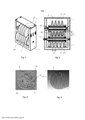
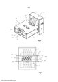
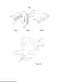
[0037] Aspectos vantajosos adicionais do método e do aparelho de acordo com a invenção se tornarão evidentes a partir da seguinte descrição das modalidades com o auxílio das figuras, em que: A figura 1 é uma vista em perspectiva de um aparelho de acordo com a invenção; A figura 2 é uma seção transversal do aparelho da figura 1 tomada ao longo de um corte de plano médio através e ao longo de um eixo central do primeiro e do segundo rolo; As Figuras 3, 4 mostram seções transversais através de um artigo em forma de haste com uma estrutura em ordem aleatória (figura 3) e em ordem otimizada (figura 4); A figura 5 é o aparelho de acordo com a figura 1 fornecido com uma unidade antirrotação; A figura 6 é uma vista frontal do aparelho de acordo com a invenção conforme a figura 5; A figura 7, 8 são uma perspectiva e uma vista superior das disposições do feixe de orientação; A figura 9 mostra uma modalidade de um feixe de orientação; A figura 10 é uma visão esquemática de um processo de tratamento do material de folha contínua em forma de haste.[0037] Additional advantageous aspects of the method and apparatus according to the invention will become apparent from the following description of the modalities with the aid of the figures, in which: Figure 1 is a perspective view of an apparatus according to invention; Figure 2 is a cross-section of the apparatus of Figure 1 taken along a midplane section through and along a central axis of the first and second roller; Figures 3, 4 show cross sections through a rod-shaped article with a structure in random order (figure 3) and in optimized order (figure 4); Figure 5 is the apparatus according to Figure 1 provided with an anti-rotation unit; Figure 6 is a front view of the apparatus according to the invention as shown in Figure 5; Figure 7, 8 is a perspective and a top view of the guide beam arrangements; Figure 9 shows an embodiment of an orientation beam; Figure 10 is a schematic view of a process for treating rod-shaped web material.
[0038] Nas figura 1 e figura 2 um primeiro rolo 1 e um segundo rolo 2 são dispostos acima uns dos outros e mantidos em uma estrutura 3, através dos eixos correspondentes 31, 32, do primeiro e do segundo rolo 1,2. O primeiro rolo 1 e o segundo rolo 2 são ambos fornecidos com uma pluralidade de cames que se deslocam circunferenci- almente 10, 20. Os cames 10,20 de cada rolo de 1,2 são dispostos em paralelo uns aos outros e são distribuídos regularmente ao longo do comprimento de cada rolo 1,2.[0038] In figure 1 and figure 2 a
[0039] O primeiro e segundo rolo 1,2 estão dispostos de forma que os cames que se deslocam circunferencialmente 10 do primeiro rolo 1, e os cames que se deslocam circunferencialmente do segundo rolo 2 acoplam entre si. Os rolos são também dispostos de modo a formar uma lacuna 30 entre os cames 10,20 do primeiro e do segundo rolo 1,2. De preferência, a forma dos cames 10 do primeiro rolo 1 e a forma dos cames 20 do segundo rolo 2 correspondem entre si de modo a formar uma lacuna constante 30 ao longo do comprimento dos rolos 1,2 mediante o acoplamento dos cames 10,20. Uma altura 11 dos ca- mes 10,20, isto é, uma distância entre o pico de onda e a calha de onda pode ser entre cerca de 25 mm e cerca de 30 mm, por exemplo, de 28 mm e uma distância de came para came (distância do pico de onda até o pico de onda) pode ser entre cerca de 15 mm e cerca de 25 mm, por exemplo, 20 mm, para que uma forma circular seja formada pelo material de folha na entrada de uma máquina que fabrica hastes, em que a entrada tem um diâmetro circular de cerca de 25 mm a cerca de 30 mm, por exemplo, de 27 mm.[0039] The first and
[0040] Através de um ajuste vertical de um ou de ambos os rolos 1,2 ou substituindo o primeiro rolo 1 ou segundo rolo 2, a largura da lacuna 30 ou uma forma da lacuna 30 pode ser ajustada. A lacuna 30 é ajustada para permitir que uma folha de material passe entre o primeiro e o segundo rolo 1,2. A lacuna 30 também é ajustada para forçar uma estrutura tipo onda correspondente à forma dos cames 10,20 que se acoplam do primeiro e do segundo rolo 1,2 no material de folha contínua orientado entre os cames. A forma da lacuna 30 pode ser criada para garantir que material de folha 4 com uma largura predeterminada possa caber completamente o projeto de onda dos cames 10,20 dos rolos. De preferência, o material de folha se estende ao longo de todo o comprimento dos rolos 1,2 e nenhum material escapa para fora dos rolos durante a fabricação. De preferência, uma lacuna 30 é ajustada posteriormente, dependendo da espessura e da rigidez de um material de folha a ser tratado. De preferência, uma lacuna entre os cames dos dois rolos é em uma faixa de entre cerca de 0,2 mm e cerca de 3 mm, mais de preferência entre cerca de 0,25 mm e 2 mm, por exemplo, entre 0,5 mm e 1,5 mm.[0040] By vertically adjusting one or both
[0041] Mediante a orientação do material de folha contínua entre o primeiro e o segundo rolo 1,2, os rolos são feitos para rolar em torno dos eixos 31,32 pela força de fricção entre o material de folha e os cames 10,20. Desse modo, uma fricção deslizante que atuaria sobre o material de folha, ao usar um membro estacionário para fornecer uma estrutura tipo onda, pode ser evitada ou minimizada através do fornecimento de dois rolos que rolam cooperando ou contrários a uma direção de transporte do material de folha, respectivamente. A força atuando sobre o material de folha devido aos rolos é localizada e limitada à região onde o primeiro e o segundo rolo 1,2 se acoplam. Esta região de acoplamento é basicamente limitada a uma linha, disposta em uma direção transversal à direção de transporte do material de folha.[0041] By orienting the web material between the first and
[0042] Os eixos 31,32 também podem ser acionados por um motor externo e uma velocidade de rotação dos rolos 1,2 pode ser sincronizada com uma velocidade linear (de transporte) do material de folha orientado entre os rolos.[0042] The shafts 31.32 can also be driven by an external motor and a rotation speed of the rollers 1.2 can be synchronized with a linear (transport) speed of the sheet material oriented between the rollers.
[0043] A figura 3 mostra uma seção transversal através de um ar tigo em forma de haste 40 com uma estrutura de ordem aleatória. Este artigo em forma de haste foi fabricado comprimindo um material de folha contínua plana, compreendendo uma estrutura de friso, mas sem sobrepor uma estrutura tipo onda em forma de haste, como conhecido na técnica. Devido à dobradura não controlada do material de folha, o produto final mostra regiões 41 de material de folha denso, regiões 42 com uma disposição frouxo do material de folha e regiões 43 sem material de folha (vazios). Os elementos de filtro produzidos dessa maneiratêm especificações, por exemplo, uma resistência à tragada, que são difíceis de serem definidas precisamente. Além disso, devido à ordem aleatória, uma reprodutibilidade dos elementos de filtro tendo as mesmas especificações também é prejudicada. Isso pode afetar especialmente os artigos para fumar compostos por diversos segmentos, em que cada segmento pode ser menor do que em artigos para fumar convencionais. Isto também pode afetar um produto, onde o material mais eficaz permite a produção de segmentos mais curtos.[0043] Figure 3 shows a cross section through a rod-shaped
[0044] A figura 4 mostra uma seção transversal através de um ar tigo em forma de haste 40 com um material de folha 4 dobrado com o método de acordo com a invenção tenso uma estrutura com ordem otimizada. Pode ser observado na figura as melhorias em comparação com a figura 3, com espaços vazios reduzidos e uma melhor distribuição geral.[0044] Figure 4 shows a cross section through a rod-shaped
[0045] Na figura 5 uma unidade antirrotação 5 é disposta próxima e a jusante (a jusante com relação a direção de transporte do material de folha) do primeiro e do segundo rolo 1,2. A unidade antirrotação 5 compreende dois feixes de orientação superiores 51 e um feixe de orientação inferior 52, disposto entre os dois feixes de orientação superiores 51. Os feixes de orientação superior e o inferior 51,52 são dispostos com um deslocamento em direções opostas perpendiculares a um plano de movimento do material de folha, em que o material de folha é guiado ao longo e entre os feixes de orientação. Os feixes de orientação 51,52 são dispostos com seus eixos longitudinais essencialmente dispostos na direção de transporte do material de folha. Feixes de orientação adicionais podem ser dispostos próximos aos feixes de orientação 51,52 para ter mais orientação para o caminho remanescente do material frisado.[0045] In figure 5 an
[0046] Os feixes de orientação 51,52 são montados para apoiar a estrutura 55. A estrutura de sustentação 55 compreende fendas 54, em que os feixes de orientação 51,52 dispostos de maneira móvel e fixados através de meios de fixação 53, por exemplo, parafusos. As fendas 54 permitem um deslocamento lateral ou transversal (transversal em relação a uma direção de transporte do material de folha) dos feixes de orientação 51,52. Isto permite uma variação de uma distância lateral de e entre os feixes de orientação. Tal uma distância entre os feixes de orientação 51,52 pode ser constante ao longo do comprimento dos feixes de orientação ou pode, como no desenho, ser redu-zida com o aumento da distância dos rolos 1,2. Em outras palavras, as extremidades a montante 511,521 dos feixes de orientação vizinhos 51,52 estão mais distanciados um do outro do que as extremidades a jusante 510,520 dos feixes de orientação vizinhos. Assim, os feixes de orientação descrevem uma direção convergente, como também pode ser visto na figura 8. Desta forma, a direção de transporte do material de folha é indicada pela seta 100 (um feixe de orientação superior 51 e dois feixes de orientação inferiores 52 são mostrados). Ao guiar o ma terial de folha fornecido com a estrutura tipo onda através do tratamento pelo primeiro e pelo segundo rolo 1,2, ao longo e entre os três feixes de orientação 51,52, a estrutura tipo onda é tomada pela disposição dos feixes de orientação. Os feixes de orientação superior e inferior interagem alternadamente com a forma de onda da estrutura tipo onda do material de folha. Por um lado, isto estabiliza o material de folha, com a estrutura tipo onda contra um movimento rotacional (através de uma disposição tipo lateral longitudinal dos feixes de orientação) enquantoé posteriormente processado. Por outro lado, isto permite uma dobradura adicional do material de folha (através da redução de sua largura) de forma guiada.[0046] The guide beams 51.52 are mounted to support the
[0047] Na figura 6 o material de folha 4 é mostrado em uma vista frontal conforme é processado na unidade antirrotação 5. A unidade antirrotação 5 é disposta em paralelo ao primeiro e ao segundo rolo 1,2 num local de forma que o material de folha 4 saindo da lacuna 30 do primeiro e do segundo rolo 1,2 é alimentado entre os feixes de orientação 51,52 de da unidade antirrotação 5, de preferência, por um movimento linear e em linha reta. Os feixes de orientação superior e inferior são dispostos com um deslocamento 58 do plano movimento 400 do material de folha 4. O deslocamento 58 é indicado somente para o feixe de orientação inferior 52.[0047] In Figure 6 the
[0048] Feixes de orientação adicionais podem ser dispostos pró ximo aos dois feixes de orientação superiores 51 e um feixe de orientação inferior 52, conforme indicado pelas linhas pontilhadas. Os feixes de orientação superior e inferior 51,52 também são dispostos de forma alternada. O número total de feixes de orientação 51,52 é ímpar para fornecer a simetria em relação ao eixo longitudinal do feixe de orientação inferior disposto centralmente 52.[0048] Additional guidance beams may be arranged close to the two upper guidance beams 51 and a
[0049] Na figura 7 os três feixes de orientação 51,52 são dispos tos em uma maneira convergente em uma direção transversal (trans versal com relação ao material de folha), semelhante àquela da figura 5. Os feixes de orientação 51,52 também são dispostos de forma convergente em relação ao plano de movimento 400 do material de folha 4. Um deslocamento 58 dos feixes de orientação em relação ao plano de movimento 400 é maior na extremidade a jusante 510 dos feixes de orientação do que na extremidade a montante 511. Os feixes de orientação podem também ter uma largura constante, como mostrado na figura 7 ou ter uma largura variável ao longo do comprimento do feixe de orientação 51, de preferência, ter uma largura menor em uma extremidade a jusante 510 do que em uma extremidade a montante 511, conforme mostrado na figura 9.[0049] In figure 7 the three guidance beams 51.52 are arranged in a converging manner in a transverse direction (transverse to the sheet material), similar to that of figure 5. The guidance beams 51.52 also are arranged convergingly with respect to the plane of
[0050] Na figura 10, uma visão esquemática de um processo de tratamento do material de folha contínua 4 em forma de haste, como preferencialmente usada na fabricação de artigos para fumar ou elementos de artigos para fumar, tais como elementos de filtro, é mostrada. O aparelho de acordo com a invenção foi omitido por razões de clareza. No entanto, a estrutura tipo onda 41 fornecida o material de folha 4, assim como a estrutura desenvolvida ao dobrar adicionalmente o material de folha 4 em forma de haste, é indicada pelas linhas 41,42. O material de folha contínua plana 4 é processado e fornecido com uma estrutura de friso que se desloca na direção longitudinal do material de folha contínua enquanto é guiado através dos dois rolos de friso 6. Para fornecer a estrutura de friso, a superfície de um ou de ambos os rolos de friso 6 pode ser fornecida com saliências, sulcos, bordas de corte, cristas e depressões, etc., como conhecido na técnica.[0050] In Figure 10, a schematic view of a process for treating the rod-shaped
[0051] A máquina ou acessório para fabricar hastes, por exemplo, que compreende um acessório de lingueta e um jato de ar 7, é disposto ainda a jusante dos rolos de friso 6 na direção de transporte do material de folha 4. No seu caminho entre rolos de friso 6 e a entrada 71 de jato de ar 7, o material de folha contínua 4 é dobrado a partir da forma plana na forma de haste definida pelo jato de ar 7. O aparelho de acordo com a invenção é disposto entre os rolos de friso 6 e o jato de ar 7 de haste para fornecer o material de folha 4 com a estrutura tipo onda 41. As larguras do primeiro e do segundo rolo 1,2 do aparelho de acordo com a invenção, são menores do que a largura de uma saída 61 dos rolos de friso 6 e são maiores do que a largura de uma entrada 71 de jato de ar 7. De preferência, uma largura do primeiro e do segundo rolo 1,2 é adaptada para a largura do material de folha 4 e para a posição longitudinal dos rolos 1,2 entre o rolo de friso 6 e o jato de ar 7 (longitudinal com relação a distância entre o frisador e a máquina que fabrica hastes). Isto permite um dobramento contínuo do material de folha 4 sem mudanças bruscas na largura e na direção de fluxo e, portanto, reduz a tensão no material de folha 4 mediante o seu tratamento. De preferência, uma largura do material de folha originalmente plano 4 (plano incluindo a estrutura de friso) é de forma que, após a inserção do material de folha entre os cames dos rolos, o material se estende até ambas as extremidades dos rolos para fazer uso de todo o comprimento dos rolos. No entanto, o material de folha, de preferência, não excede as extremidades dos rolos para evitar a compressão descontrolada do material de folha e ter material de folha fornecido sem a estrutura tipo onda. Depois de fornecer o material de folha 4 com a estrutura tipo onda 41, o material de folha é dobrado de acordo com a estrutura tipo onda e, de forma estruturada, levado a sua forma de haste final na máquina que fabrica hastes.[0051] The machine or accessory for making rods, for example, comprising a tongue accessory and an
Claims (13)
Applications Claiming Priority (1)
| Application Number | Priority Date | Filing Date | Title |
|---|---|---|---|
| EP13199457.6 | 2013-12-23 |
Publications (1)
| Publication Number | Publication Date |
|---|---|
| BR112016012169B1 true BR112016012169B1 (en) | 2021-10-13 |
Family
ID=
Similar Documents
| Publication | Publication Date | Title |
|---|---|---|
| KR102296772B1 (en) | Method and apparatus for treating continuous sheet material | |
| CN105473010B (en) | Method and apparatus for making variable crimped web material | |
| BR112017010156B1 (en) | METHOD AND APPARATUS TO FORM SUBSTANTIALLY SMOOTH CONTINUOUS MATERIAL | |
| CN104621710A (en) | Embossing roll | |
| CN103416846A (en) | Embossing roller | |
| KR20220066063A (en) | Apparatus for manufacturing an aerosol-generating rod | |
| EP3589142B1 (en) | Apparatus and method for treatment of wrapping material | |
| US20120280427A1 (en) | Method and device for producing coils from wires | |
| BR112016012169B1 (en) | METHOD FOR TREATMENT OF CONTINUOUS LEAF MATERIAL, APPARATUS FOR TREATMENT OF CONTINUOUS LEAF MATERIAL, INSTALLATION AND USE | |
| EP2508327B1 (en) | Device and method for processing a tape | |
| EP3624616B1 (en) | Method and apparatus to form a rod for an aerosol generating article from a sheet of material | |
| CN104872818B (en) | Method and device for producing a rod for the tobacco processing industry | |
| CN207984153U (en) | Equidistant compound lamination paper web molding machine | |
| RU2019136695A (en) | DEVICE AND METHOD FOR PRODUCING TOBACCO MATERIAL IN SHEET FORM | |
| KR101344717B1 (en) | Apparatus for supplying enveloping film | |
| US6038904A (en) | Decamberer | |
| PL243624B1 (en) | Method and device for the production of bars | |
| ITBO970036A1 (en) | FEEDING UNIT FOR A BELT OF WRAPPING MATERIAL FOR THE CREATION OF COLLARS FOR RIGID PACKAGES WITH HINGED LID | |
| ITFI940121A1 (en) | EQUIPMENT FOR THE AUTOMATIC AND CONTINUOUS PRODUCTION OF AN OPEN TUBULAR SEMI-WORK IN PRECIOUS METAL WITH A NON-PRICE METAL CORE |