BR112016008269B1 - ANTI-FREEZING APPARATUS AND METHOD FOR AIRCRAFT - Google Patents
ANTI-FREEZING APPARATUS AND METHOD FOR AIRCRAFT Download PDFInfo
- Publication number
- BR112016008269B1 BR112016008269B1 BR112016008269-9A BR112016008269A BR112016008269B1 BR 112016008269 B1 BR112016008269 B1 BR 112016008269B1 BR 112016008269 A BR112016008269 A BR 112016008269A BR 112016008269 B1 BR112016008269 B1 BR 112016008269B1
- Authority
- BR
- Brazil
- Prior art keywords
- air
- aircraft
- tube
- engine
- heating
- Prior art date
Links
Images


Classifications
-
- B—PERFORMING OPERATIONS; TRANSPORTING
- B64—AIRCRAFT; AVIATION; COSMONAUTICS
- B64D—EQUIPMENT FOR FITTING IN OR TO AIRCRAFT; FLIGHT SUITS; PARACHUTES; ARRANGEMENTS OR MOUNTING OF POWER PLANTS OR PROPULSION TRANSMISSIONS IN AIRCRAFT
- B64D13/00—Arrangements or adaptations of air-treatment apparatus for aircraft crew or passengers, or freight space, or structural parts of the aircraft
- B64D13/06—Arrangements or adaptations of air-treatment apparatus for aircraft crew or passengers, or freight space, or structural parts of the aircraft the air being conditioned
- B64D13/08—Arrangements or adaptations of air-treatment apparatus for aircraft crew or passengers, or freight space, or structural parts of the aircraft the air being conditioned the air being heated or cooled
-
- B—PERFORMING OPERATIONS; TRANSPORTING
- B64—AIRCRAFT; AVIATION; COSMONAUTICS
- B64D—EQUIPMENT FOR FITTING IN OR TO AIRCRAFT; FLIGHT SUITS; PARACHUTES; ARRANGEMENTS OR MOUNTING OF POWER PLANTS OR PROPULSION TRANSMISSIONS IN AIRCRAFT
- B64D15/00—De-icing or preventing icing on exterior surfaces of aircraft
- B64D15/02—De-icing or preventing icing on exterior surfaces of aircraft by ducted hot gas or liquid
- B64D15/04—Hot gas application
-
- B—PERFORMING OPERATIONS; TRANSPORTING
- B64—AIRCRAFT; AVIATION; COSMONAUTICS
- B64D—EQUIPMENT FOR FITTING IN OR TO AIRCRAFT; FLIGHT SUITS; PARACHUTES; ARRANGEMENTS OR MOUNTING OF POWER PLANTS OR PROPULSION TRANSMISSIONS IN AIRCRAFT
- B64D33/00—Arrangements in aircraft of power plant parts or auxiliaries not otherwise provided for
- B64D33/02—Arrangements in aircraft of power plant parts or auxiliaries not otherwise provided for of combustion air intakes
- B64D2033/0233—Arrangements in aircraft of power plant parts or auxiliaries not otherwise provided for of combustion air intakes comprising de-icing means
Abstract
aparelho e método de anticongelamento para aeronaves. a presente invenção refere-se a um método e aparelho para aquecimento de uma superfície de uma aeronave. um fluxo de ar é recebido de uma parte de um motor (220) em um sistema de tubo (300). o ar que flui através do sistema de tubo (300) é aquecido por um sistema de aquecimento (302) e enviado para a superfície da aeronave. o fluxo de ar da parte do motor (220) e o sistema de aquecimento (302) para aquecer a superfície da aeronave são controlados por um controlador (304). as condições de formação de gelo na superfície da aeronave são deste modo reduzidas.aircraft antifreeze apparatus and method. The present invention relates to a method and apparatus for heating an aircraft surface. an air stream is received from a motor part (220) in a tube system (300). the air flowing through the tube system (300) is heated by a heating system (302) and sent to the surface of the aircraft. the airflow from the engine part (220) and the heating system (302) for heating the surface of the aircraft are controlled by a controller (304). icing conditions on the surface of the aircraft are thereby reduced.
Description
[001] A presente invenção refere-se genericamente à aeronave e às condições de formação de gelo e, em particular, à redução das condições de formação de gelo para a aeronave. Ainda mais particularmente, a presente descrição refere-se a um método e aparelho para um sistema anticongelamento para aeronaves.[001] The present invention relates generally to aircraft and icing conditions and, in particular, to reducing icing conditions for aircraft. Even more particularly, the present description relates to a method and apparatus for an anti-icing system for aircraft.
[002] Na aviação, congelamento em uma aeronave pode ocorrer quando as condições atmosféricas levam à formação de gelo nas superfícies da aeronave. Em alguns casos, a formação de gelo também pode ocorrer dentro do motor. Formação de gelo nas superfícies da aeronave, nas entradas de um motor, e em outros locais é indesejável e potencialmente perigosa para o funcionamento da aeronave. Quando ocorrem estas condições, a formação de gelo pode reduzir o desempenho da aeronave de um modo indesejado.[002] In aviation, icing on an aircraft can occur when atmospheric conditions lead to the formation of ice on aircraft surfaces. In some cases, ice formation can also occur inside the engine. Ice formation on aircraft surfaces, engine inlets, and other locations is undesirable and potentially dangerous to the operation of the aircraft. When these conditions occur, icing can reduce aircraft performance in an undesired way.
[003] Condições de formação de gelo podem ocorrer quando gotas de água líquida super-resfriadas estão presentes. Nestes exemplos ilustrativos, a água é considerada que está sobre-resfriada, quando a água é arrefecida abaixo do ponto de congelamento indicado, porém, ainda está na forma líquida. Condições de formação de gelo podem ser caracterizadas pelo tamanho das gotas, o conteúdo de água líquida, temperatura do ar, e outros parâmetros. Estes parâmetros podem afetar a velocidade e a extensão em que o gelo se forma sobre uma aeronave.[003] Ice forming conditions can occur when supercooled liquid water droplets are present. In these illustrative examples, water is considered to be overcooled when the water is cooled below the indicated freezing point but is still in liquid form. Ice formation conditions can be characterized by droplet size, liquid water content, air temperature, and other parameters. These parameters can affect the speed and extent to which ice forms on an aircraft.
[004] Quando ocorre gelo, a aeronave pode não funcionar como desejado. Por exemplo, gelo sobre a asa de um avião pode fazer com[004] When ice occurs, the aircraft may not function as intended. For example, ice on the wing of an airplane can cause
[005] que a aeronave se desempenhe de modo indesejável a um ângulo de ataque mais elevado. Esta situação pode reduzir a eficiência do combustível para a aeronave ou reduzir a velocidade de estolar de voo nivelado.[005] that the aircraft undesirably perform at a higher angle of attack. This situation can reduce fuel efficiency for the aircraft or reduce stall speed from level flight.
[006] As aeronaves podem ter mecanismos para evitar gelo, remover o gelo, ou alguma combinação destes para lidar com essas condições de formação de gelo. Por exemplo, as aeronaves podem incluir sistemas de proteção de gelo que detectam gelo sobre a aeronave, impedem a formação de gelo na superfície da aeronave, removem o gelo da superfície da aeronave, ou alguma combinação dos mesmos. Estes sistemas de proteção gelo podem ser designados como sistemas anticongelamento. O gelo pode ser impedido de se formar sobre a superfície da aeronave usando ar de sangria, aquecimento por infravermelhos, e outros mecanismos adequados.[006] Aircraft may have de-icing, de-icing, or some combination of these mechanisms to deal with these icing conditions. For example, aircraft may include ice protection systems that detect ice on the aircraft, prevent ice from forming on the surface of the aircraft, remove ice from the surface of the aircraft, or some combination of these. These frost protection systems can be referred to as anti-freeze systems. Ice can be prevented from forming on the surface of the aircraft using bleed air, infrared heating, and other suitable mechanisms.
[007] Em alguns casos, no entanto, sistemas anticongelamento para aeronaves podem ser mais dispendiosos do que o desejado, devido ao tamanho, peso, complexidade e outros fatores que podem estar presentes com determinados tipos de aeronaves. Além disso, alguns sistemas anticongelamento para as aeronaves podem usar mais energia do que o desejado ou podem aumentar a temperatura da superfície da aeronave mais do que o desejado em várias condições ambientais. Portanto, seria desejável ter um método e um aparelho que tenha em conta, pelo menos, alguns dos problemas discutidos acima, bem como outros possíveis problemas.[007] In some cases, however, anti-icing systems for aircraft may be more expensive than desired, due to the size, weight, complexity, and other factors that may be present with certain types of aircraft. In addition, some anti-icing systems for aircraft may use more power than desired or may increase the surface temperature of the aircraft more than desired under various environmental conditions. Therefore, it would be desirable to have a method and an apparatus that takes into account at least some of the problems discussed above, as well as other possible problems.
[008] Em uma concretização ilustrativa, um aparelho compreende um sistema de tubo e um sistema de aquecimento fisicamente associado com o sistema de tubo. O sistema de tubo é configurado para receber ar de uma parte de um motor. O sistema de tubo é adicionalmente configurado para dirigir o ar a uma superfície de uma aeronave. O sistema de aquecimento está configurado para aquecer o ar que flui através do sistema de tubo.[008] In an illustrative embodiment, an apparatus comprises a tube system and a heating system physically associated with the tube system. The tube system is configured to receive air from a part of an engine. The tube system is additionally configured to direct air to an aircraft surface. The heating system is configured to heat the air flowing through the pipe system.
[009] Em uma outra concretização ilustrativa, um método para o aquecimento de uma superfície de um avião é fornecido. Um fluxo de ar é recebido de uma parte de um motor em um sistema de tubo. O ar que flui através do sistema de tubo é aquecido. O ar é enviado para a superfície da aeronave. O fluxo de ar da parte do motor e o sistema de aquecimento para aquecer a superfície da aeronave são controlados. As condições de formação de gelo na superfície da aeronave são reduzidas.[009] In another illustrative embodiment, a method for heating a surface of an airplane is provided. A stream of air is received from a part of an engine in a tube system. The air flowing through the tube system is heated. Air is sent to the surface of the aircraft. The airflow from the engine part and the heating system to heat the surface of the aircraft are controlled. Icing conditions on the aircraft surface are reduced.
[0010] Ainda em outra concretização ilustrativa, um sistema anticongelamento de aeronave compreende um sistema de tubo, um sistema de aquecimento fisicamente associado com o sistema de tubo, um bocal, uma válvula fisicamente associada com um tubo, um sistema de sensores, e um controlador. O sistema de tubo é configurado para receber ar de uma parte de um motor. O sistema de tubo é adicionalmente configurado para enviar o ar para uma superfície de uma aeronave. O sistema de aquecimento está configurado para aquecer o ar que flui através do sistema de tubo. O bocal está configurado para dirigir um fluxo de ar para dentro de uma entrada pelo motor. A válvula é configurada para ser movida para controlar o fluxo do ar através do sistema de tubo. O sistema de detecção está configurado para gerar informação sobre, pelo menos, de uma pressão interna ou de uma temperatura. O controlador é configurado para controlar o fluxo de ar da parte do motor. O controlador é, ainda, configurado para controlar o sistema de aquecimento para aquecer a superfície da aeronave. As condições de formação de gelo na superfície da aeronave são reduzidas.[0010] In yet another illustrative embodiment, an aircraft antifreeze system comprises a tube system, a heating system physically associated with the tube system, a mouthpiece, a valve physically associated with a tube, a sensor system, and a controller. The tube system is configured to receive air from a part of an engine. The tube system is additionally configured to send air to an aircraft surface. The heating system is configured to heat the air flowing through the pipe system. The nozzle is configured to direct a flow of air into an inlet through the engine. The valve is configured to be moved to control the flow of air through the pipe system. The detection system is configured to generate information on at least one internal pressure or temperature. The controller is configured to control the airflow from the engine part. The controller is further configured to control the heating system to heat the surface of the aircraft. Icing conditions on the aircraft surface are reduced.
[0011] As características e funções podem ser conseguidas de forma independente em várias concretizações da presente descrição ou podem ser combinadas ainda em outras concretizações em que mais detalhes podem ser vistos com referência à seguinte descrição e desenhos.[0011] The features and functions can be independently achieved in various embodiments of the present description or can be combined in still other embodiments where more details can be seen with reference to the following description and drawings.
[0012] As novas características acreditadas características das concretizações ilustrativas estão estabelecidas nas reivindicações anexas. As concretizações ilustrativas, no entanto, bem como um modo preferido de utilização, objetivos adicionais e características dos mesmos, serão melhor compreendidos pela referência à descrição detalhada que se segue de uma concretização ilustrativa da presente descrição quando lida em conjunto com os desenhos anexos, nos quais:[0012] The new believed features characteristic of the illustrative embodiments are set forth in the appended claims. Illustrative embodiments, however, as well as a preferred mode of use, additional purposes and features thereof, will be better understood by reference to the following detailed description of an illustrative embodiment of the present description when read in conjunction with the accompanying drawings, in which are:
[0013] A Figura 1 é uma ilustração de uma aeronave de acordo com uma concretização ilustrativa;[0013] Figure 1 is an illustration of an aircraft according to an illustrative embodiment;
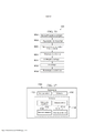
[0014] A Figura 2 é uma ilustração de um diagrama de blocos de um ambiente anticongelamento, de acordo com uma concretização ilustrativa;[0014] Figure 2 is a block diagram illustration of an antifreeze environment, according to an illustrative embodiment;
[0015] A Figura 3 é uma ilustração de um diagrama de blocos de um sistema anticongelamento, de acordo com uma concretização ilustrativa;[0015] Figure 3 is a block diagram illustration of an antifreeze system, according to an illustrative embodiment;
[0016] A Figura 4 é uma ilustração de uma vista isométrica de um motor com um sistema anticongelamento, de acordo com uma concretização ilustrativa;[0016] Figure 4 is an illustration of an isometric view of an engine with an anti-freeze system, according to an illustrative embodiment;
[0017] A Figura 5 é uma ilustração de um motor com um sistema anticongelamento, de acordo com uma concretização ilustrativa;[0017] Figure 5 is an illustration of an engine with an anti-freeze system, according to an illustrative embodiment;
[0018] A Figura 6 é uma outra ilustração de um motor com um sistema anticongelamento, de acordo com uma concretização ilustrativa;[0018] Figure 6 is another illustration of an engine with an anti-freeze system, according to an illustrative embodiment;
[0019] A Figura 7 é também uma ilustração de um motor com um sistema anticongelamento, de acordo com uma concretização ilustrativa;[0019] Figure 7 is also an illustration of an engine with an anti-freeze system, according to an illustrative embodiment;
[0020] A Figura 8 é uma ilustração de uma vista lateral de um motor com um sistema anticongelamento, de acordo com uma concretização ilustrativa;[0020] Figure 8 is an illustration of a side view of an engine with an anti-freeze system, according to an illustrative embodiment;
[0021] A Figura 9 é uma ilustração de uma vista em perspectiva de um motor com um sistema anticongelamento, de acordo com uma concretização ilustrativa;[0021] Figure 9 is an illustration of a perspective view of an engine with an anti-freeze system, according to an illustrative embodiment;
[0022] A Figura 10 é uma ilustração de uma vista isométrica de um motor com um sistema anticongelamento, de acordo com uma concretização ilustrativa;[0022] Figure 10 is an illustration of an isometric view of an engine with an anti-freeze system, according to an illustrative embodiment;
[0023] A Figura 11 é uma ilustração de uma vista em perspectiva de um motor com um sistema anticongelamento, de acordo com uma concretização ilustrativa;[0023] Figure 11 is an illustration of a perspective view of an engine with an anti-freeze system, according to an illustrative embodiment;
[0024] A Figura 12 é uma ilustração de um motor com um sistema anticongelamento, de acordo com uma concretização ilustrativa;[0024] Figure 12 is an illustration of an engine with an anti-freeze system, according to an illustrative embodiment;
[0025] A Figura 13 é uma outra ilustração de um motor com um sistema anticongelamento, de acordo com uma concretização ilustrativa;[0025] Figure 13 is another illustration of an engine with an anti-freeze system, according to an illustrative embodiment;
[0026] A Figura 14 é uma ilustração de uma asa com um sistema anticongelamento, de acordo com uma concretização ilustrativa;[0026] Figure 14 is an illustration of a wing with an antifreeze system, according to an illustrative embodiment;
[0027] A Figura 15 é uma ilustração de um fluxograma de um processo para o aquecimento de uma superfície de uma aeronave de acordo com uma concretização ilustrativa;[0027] Figure 15 is an illustration of a flowchart of a process for heating an aircraft surface according to an illustrative embodiment;
[0028] A Figura 16 é uma ilustração de um diagrama de blocos de uma fabricação de aeronave e método de manutenção de acordo com uma concretização ilustrativa;[0028] Figure 16 is a block diagram illustration of an aircraft manufacturing and maintenance method according to an illustrative embodiment;
[0029] A Figura 17 é uma ilustração de um diagrama de blocos de uma aeronave na qual uma concretização ilustrativa pode ser implementada; e[0029] Figure 17 is an illustration of a block diagram of an aircraft in which an illustrative embodiment can be implemented; and
[0030] A Figura 18 é uma ilustração de um diagrama de blocos de um sistema de processamento de dados de acordo com uma concretização ilustrativa.[0030] Figure 18 is a block diagram illustration of a data processing system according to an illustrative embodiment.
[0031] As concretizações ilustrativas reconhecem e levam em conta uma ou mais considerações diferentes. Por exemplo, as concretizações ilustrativas reconhecem e levam em conta que pode ser desejável proporcionar um sistema anticongelamento que utiliza ar de sangria recebido de uma parte de um motor antes do trabalho ter sido realizado no ar. Neste exemplo ilustrativo, "ar de sangria" refere-se ao ar tomado de dentro de uma parte de um motor. Este ar de sangria pode ser comprimido. Nestes exemplos ilustrativos, ar é considerado para ser comprimido quando o ar tem uma pressão maior do que o ar que entra na aeronave. Muitas vezes, este ar comprimido é tomado do compressor no motor em um ou mais estágios do compressor.[0031] The illustrative embodiments recognize and take into account one or more different considerations. For example, the illustrative embodiments recognize and take into account that it may be desirable to provide an antifreeze system that utilizes bleed air received from a part of an engine before work has been performed in the air. In this illustrative example, "bleed air" refers to air taken in from within a part of an engine. This bleed air can be compressed. In these illustrative examples, air is considered to be compressed when the air has a higher pressure than the air entering the aircraft. Often this compressed air is taken from the compressor into the engine at one or more compressor stages.
[0032] As concretizações ilustrativas reconhecem e levam em conta que quanto mais cedo no processo este ar de sangria puder ser extraído do motor, a menos trabalho pode ser necessário de ser executado no ar de purga. Por conseguinte, as concretizações ilustrativas reconhecem e levam em conta que pode ser desejável tomar ar de sangria de um estágio inferior de um compressor de um motor. Quando o ar é tomado do compressor em um estágio inferior, menos energia pode ser necessária para fornecer ar para o sistema anticongelamento.[0032] The illustrative embodiments recognize and take into account that the earlier in the process this bleed air can be extracted from the engine, the less work may need to be performed on the purge air. Therefore, the illustrative embodiments recognize and take into account that it may be desirable to bleed air from a lower stage of an engine compressor. When air is taken from the compressor at a lower stage, less energy may be needed to supply air to the antifreeze system.
[0033] As concretizações ilustrativas também reconhecem e levam em conta que pode ser desejável proporcionar um sistema anticongelamento que seja menos propenso a encontros indesejados com detritos, enquanto a aeronave estiver em operação. Por exemplo, em alguns casos, os componentes de um sistema anticongelamento podem ser dispostos de tal modo que alguns componentes são expostos ao ambiente em torno da aeronave. Durante o voo, esses componentes podem enfrentar encontros indesejados com as condições atmosféricas, detritos e outros materiais que podem prejudicar os componentes. Como resultado, manutenção, calibragem, e retrabalho podem aumentar o custo do sistema anticongelamento mais do que o desejado.[0033] The illustrative embodiments also recognize and take into account that it may be desirable to provide an anti-icing system that is less prone to unwanted encounters with debris while the aircraft is in operation. For example, in some cases, components of an anti-icing system may be arranged in such a way that some components are exposed to the environment around the aircraft. During flight, these components may experience unwanted encounters with atmospheric conditions, debris and other materials that can harm the components. As a result, maintenance, calibration, and rework can increase the cost of the antifreeze system more than desired.
[0034] As concretizações ilustrativas reconhecem adicionalmente e levam em conta que pode ser desejável reduzir o custo e a complexidade de um sistema anticongelamento usado para aeronaves. Em alguns casos, os sistemas anticongelamento podem incluir mais componentes, requerem mais manutenção e consomem mais energia do que o desejado.[0034] The illustrative embodiments further recognize and take into account that it may be desirable to reduce the cost and complexity of an anti-icing system used for aircraft. In some cases, antifreeze systems may include more components, require more maintenance, and consume more energy than intended.
[0035] Assim, as concretizações ilustrativas, fornecem um método e um aparelho para reduzir as condições e formação de gelo em uma superfície de uma aeronave. Um aparelho compreende um sistema de tubo, um sistema de aquecimento, e um controlador. O sistema de tubo é configurado para receber ar de uma parte de um motor e enviar o ar para uma superfície de uma aeronave. O sistema de aquecimento está fisicamente associado com o sistema de tubo. O sistema de aquecimento está configurado para aquecer o ar que flui através do sistema de tubo. O controlador é configurado para controlar um fluxo de ar da parte do motor. O controlador é, ainda, configurado para controlar o sistema de aquecimento para aquecer a superfície da aeronave de tal modo que as condições de formação de gelo na superfície da aeronave são reduzidas.[0035] Thus, the illustrative embodiments provide a method and an apparatus for reducing icing conditions and formation on an aircraft surface. An apparatus comprises a tube system, a heating system, and a controller. The tube system is configured to receive air from an engine part and send the air to an aircraft surface. The heating system is physically associated with the pipe system. The heating system is configured to heat the air flowing through the pipe system. The controller is configured to control an airflow from the engine part. The controller is further configured to control the heating system to heat the surface of the aircraft in such a way that icing conditions on the surface of the aircraft are reduced.
[0036] Referindo-nos agora às figuras e, em particular, com referência à Figura 1, uma ilustração de uma aeronave é descrita de acordo com uma concretização ilustrativa. Neste exemplo ilustrativo, a aeronave 100 tem asa 102 e asa 104 acoplada ao corpo 106. A aeronave 100 inclui o motor 108 acoplado à asa 102 e o motor 110 acoplado à asa 104.[0036] Referring now to the figures and, in particular, with reference to Figure 1, an illustration of an aircraft is described according to an illustrative embodiment. In this illustrative example,
[0037] O corpo 106 tem a seção da cauda 112. Estabilizador horizontal 114, estabilizador horizontal 116, e o estabilizador vertical 118 estão ligados à seção da cauda 112 do corpo 106.[0037]
[0038] Aeronave 100 é um exemplo de uma aeronave, em que um sistema anticongelamento pode ser implementado de acordo com uma concretização ilustrativa. Neste exemplo ilustrativo, um sistema de anticongelamento pode ser um sistema configurado para reduzir condições de formação de gelo sobre uma superfície de uma aeronave. Como um exemplo, um sistema anticongelamento pode impedir substancialmente a formação de gelo na superfície da aeronave, remover o gelo da superfície da aeronave, ou alguma combinação dos mesmos.[0038]
[0039] Em alguns exemplos, o sistema anticongelamento pode ser utilizado para aquecer o ar para reduzir as condições de formação de gelo em uma ou mais superfícies da aeronave 100. Por exemplo, o sistema anticongelamento pode ser utilizado para aquecer o ar para reduzir as condições de formação de gelo em superfícies selecionadas de pelo menos, uma asa 102, asa 104, motor 108, motor 110, seção da cauda 112, ou outras superfícies na aeronave 100.[0039] In some examples, the antifreeze system may be used to heat the air to reduce icing conditions on one or more surfaces of the
[0040] Conforme utilizada neste documento, a frase "pelo menos um de", quando utilizada com uma lista de itens, significa diferentes combinações de um ou mais dos itens listados pode ser usado e apenas um dos itens na lista pode ser necessário. O item pode ser um objeto em particular, coisa, ou categoria. Em outras palavras, "pelo menos um de" significa qualquer combinação de itens ou número de itens pode ser utilizado a partir da lista, mas nem todos os itens da lista podem ser necessários.[0040] As used in this document, the phrase "at least one of", when used with a list of items, means different combinations of one or more of the listed items may be used and only one of the items in the list may be required. The item can be a particular object, thing, or category. In other words, "at least one of" means any combination of items or number of items can be used from the list, but not all items in the list may be required.
[0041] Por exemplo, "pelo menos um item A, B ou C" pode significar item A; item a e item B; item B; item A, item B e item C, ou item B e item C. Em alguns casos "pelo menos um item A, item B e item C" pode significar, por exemplo, sem limitação, dois do item A, um do item B, e dez do item C; quatro do item B e sete do item C; ou alguma outra combinação adequada.[0041] For example, "at least one item A, B or C" can mean item A; item a and item B; item B; item A, item B and item C, or item B and item C. In some cases "at least one item A, item B and item C" can mean, for example, without limitation, two from item A, one from item B , and ten of item C; four from item B and seven from item C; or some other suitable combination.
[0042] A ilustração de aeronave 100 na figura 1 não pretende implicar limitações físicas ou arquitetônicas da maneira pela qual uma concretização ilustrativa pode ser implementada. Por exemplo, apesar da aeronave 100 ser mostrada como um avião comercial, a aeronave 100 pode também ser uma aeronave militar, uma aeronave de asa rotativa, um helicóptero, um veículo aéreo não tripulado, ou qualquer outra aeronave adequada.[0042] The
[0043] Com referência a seguir à Figura 2, uma ilustração de um diagrama de blocos de um ambiente anticongelamento, de acordo com uma concretização ilustrativa; Neste exemplo descrito, o ambiente anticongelamento 200 está ilustrado com a plataforma 202.[0043] Referring next to Figure 2, a block diagram illustration of an antifreeze environment, according to an illustrative embodiment; In this example described,
[0044] Neste exemplo ilustrativo, a plataforma 202 pode assumir a forma de aeronave 204. As aeronaves 100 na Figura 1 é um exemplo de uma implementação de aeronave 204 mostrado nesta figura.[0044] In this illustrative example,
[0045] Conforme ilustrado aeronave 204 inclui uma série de superfícies 206 e sistema anticongelamento 208. Tal como aqui utilizado, uma série de itens pode ser um ou mais itens. Por exemplo, o número de superfícies 206 pode ser uma ou mais superfícies.[0045] As illustrated,
[0046] Neste exemplo ilustrativo, o número de superfícies 206 inclui a superfície 210. A superfície 210 pode ser selecionada a partir pelo menos um dos motores 212, painel de forro, uma asa, fuselagem, ou alguma outra superfície adequada em aeronaves 204. Superfície 210 também pode ser selecionada a partir pelo menos de uma superfície externa 209 ou superfície interna 211 da aeronave 204.[0046] In this illustrative example, the number of
[0047] Neste exemplo descrito, superfície externa 209 é uma superfície de aeronave 204 exposta a um ambiente em torno do exterior da aeronave 204. Por exemplo, sem limitação, a superfície exterior 209 pode ser painel de forro em uma asa da aeronave 204. A superfície interna 211 é uma superfície no interior de uma aeronave 204 e pode não estar exposta ao ambiente no exterior da aeronave 204. Por exemplo, sem limitação, a superfície interna 211 pode ser uma parede interna da cabine da fuselagem.[0047] In this described example,
[0048] Neste exemplo ilustrativo, o motor 212 pode ser um motor de turbina a gás 213. O motor de turbina a gás 213 é um motor de combustão interna para aeronaves 204. Em outros exemplos ilustrativos, o motor 212 pode ser um tipo de motor diferente do motor de turbina a gás 213. Quando o motor 212 é um motor de turbina a gás 213, motor 212 inclui uma parte de admissão, um compressor, uma parte de combustão, uma turbina, e outros componentes adequados.[0048] In this illustrative example, the
[0049] Como descrito, a série de superfícies 206 pode experimentar condições de formação de gelo 214. Em particular, a superfície 210 na série de superfícies 206 pode experimentar a formação de gelo 216 quando as condições de formação de gelo 214 estão presentes no ambiente em torno de aeronave 204.[0049] As described, the array of
[0050] As condições de formação de gelo 214 podem ocorrer quando a aeronave 204 está em vários estágios de operação, incluindo, por exemplo, sem limitação, no taxiamento, na decolagem, na subida, em cruzeiro, na descida, no pouso, e outras fases apropriadas de operação. Em outros exemplos ilustrativos, as condições de formação de gelo 214 podem ser simuladas durante os testes da aeronave 204. Estes diferentes estágios de funcionamento também podem ser designados como as fases de voo para aeronaves 204.[0050] Icing
[0051] Tal como ilustrado, o sistema anticongelamento 208 pode ser configurado para impedir substancialmente a formação de gelo 216 na superfície 210 da aeronave 204, remover o gelo 216 da superfície 210 da aeronave 204, ou uma combinação destes recursos. Por exemplo, o sistema anticongelamento 208 pode impedir o gelo 216 de se formar na superfície 210 dentro das tolerâncias desejadas. Em outras palavras, o sistema 208 de anticongelamento pode ser configurado para evitar que qualquer gelo 216 se forme na superfície 210, impedindo que se forme gelo 216 sobre a superfície 210 com uma espessura particular, ou ambos. Em outros exemplos ilustrativos, sistema anticongelamento 208 pode derreter o gelo 216 formado na superfície 210, quando as condições de formação de gelo 214 estão presentes.[0051] As illustrated, the
[0052] Neste exemplo ilustrativo, o sistema anticongelamento 208 pode impedir o gelo 216 de se formar na superfície 210 da aeronave 204 utilizando ar 218 do motor 212 da aeronave 204. Em particular, o sistema anticongelamento 208 pode impedir o gelo 216 de se formar na superfície 210 da aeronave 204 usando ar 218 a partir da parte 220 do motor 212. Em um exemplo, a parte 220 pode ser um compressor de turbina a gás 213. Em outros exemplos, a parte 220 pode ser uma parte diferente do motor 212, dependendo da implementação particular. Por exemplo, a parte 220 pode ser a parte de combustão ou qualquer outra parte adequada do motor 212.[0052] In this illustrative example, the
[0053] Ar 218 pode ser ar de sangria 219 neste exemplo ilustrativo. O ar 218 pode incluir, pelo menos, um ar aquecido 222 ou um ar comprimido 224. O ar aquecido 222 pode ser ar 218 aquecido a uma temperatura desejada nestes exemplos ilustrativos. A temperatura desejada para o ar aquecido 222 pode ser selecionada para evitar a formação de gelo 216 na superfície 210 da aeronave 204.[0053]
[0054] Neste exemplo descrito, o ar pressurizado 224 pode ser ar comprimido retirado do motor 212. O ar pressurizado 224 pode ser comprimido no compressor do motor 212 a uma pressão desejada, que pode ser maior do que a pressão atmosférica. Por exemplo, sem limitação, o ar pressurizado 224 pode ser comprimido a 40 libras por polegada quadrada (PSI). Em outros exemplos, o ar pressurizado 224 pode ser comprimido para outras pressões adequadas, dependendo da implementação particular. Neste exemplo ilustrativo, o ar pressurizado 224 pode ser comprimido a uma pressão tal que o ar 218 atinge da superfície 210 da aeronave 204 de uma maneira desejada.[0054] In this described example,
[0055] Passando a seguir à Figura 3, uma ilustração de um diagrama de blocos de um sistema anticongelamento, de acordo com uma concretização ilustrativa; Neste exemplo descrito, é mostrada uma ilustração mais detalhada do sistema anticongelamento 208 em uma aeronave 204 da Figura 2.[0055] Turning next to Figure 3, an illustration of a block diagram of an antifreeze system, according to an illustrative embodiment; In this described example, a more detailed illustration of the
[0056] Conforme representado, o sistema anticongelamento 208 compreende um sistema de tubo 300, sistema de aquecimento 302 e controlador 304. Neste exemplo ilustrativo, o sistema de tubo 300 está configurado para receber ar 218 a partir da parte 220 do motor 212 e enviar o ar 218 para a superfície 210 da aeronave 204 na Figura 2. Em outras palavras, o fluxo 306 do ar 218 pode viajar através sistema de tubo 300 para a superfície 210 da aeronave 204.[0056] As shown, the
[0057] Neste exemplo descrito, o sistema de aquecimento 302 está associado com o sistema de tubo 300. Conforme aqui utilizado, quando um componente está "associado" com um outro componente, a associação é uma associação física nos exemplos ilustrados. Por exemplo, um primeiro componente, tal como o sistema de aquecimento 302, pode ser considerado que está associado a um segundo componente, tal como o sistema de tubo 300, por estar fixado ao segundo componente, ligado ao segundo componente, montado no segundo componente, soldado ao segundo componente, preso ao segundo componente, e / ou conectado ao segundo componente, de alguma outra maneira adequada. O primeiro componente também pode estar conectado ao segundo componente utilizando um terceiro componente. Além disso, o primeiro componente pode ser considerado estar associado com o segundo componente por ser formado como parte de e/ou como uma extensão do segundo componente.[0057] In this described example, the
[0058] Tal como ilustrado, o sistema de aquecimento 302 está configurado para aquecer o ar que flui através do sistema 218 do tubo 300. Neste exemplo, o sistema de aquecimento 302 pode ser disposto ao longo do sistema de tubo 300 em um local desejado. Esta localização pode ser selecionada ao longo sistema de tubo 300 de tal modo que o consumo de energia e perda de calor são reduzidos. Por exemplo, o sistema de aquecimento 302 pode ser disposto em uma extremidade do sistema de tubo 300 parte oposta 220 do motor 212 de tal forma que o ar 218 é aquecido por um sistema de aquecimento 302 logo antes do ar 218 ser direcionado para a superfície 210 da aeronave 204. Deste modo, menos trabalho pode ser realizado no ar 218 para conseguir o ar 218 a uma temperatura desejada. Como resultado, pelo menos um consumo de energia do sistema de anticongelamento 208 ou perda de calor durante o deslocamento através do sistema de tubo 300 no sistema de anticongelamento 208 pode ser reduzido.[0058] As illustrated, the
[0059] Neste exemplo ilustrativo, o controlador 304 pode ser configurado para controlar o fluxo 306 de ar de 218 a partir da parte 220 do motor 212. Por exemplo, o controlador 304 pode ser configurado para controlar o fluxo 306 de ar de 218 da parte 220 do motor 212 usando uma série de válvulas 308.[0059] In this illustrative example,
[0060] Neste exemplo ilustrativo, o controlador 304 pode ser implementado em software, hardware, firmware, ou uma combinação dos mesmos. Quando o software é utilizado, as operações executadas pelo controlador 304 podem ser implementadas utilizando, por exemplo, sem limitação, o código do programa configurado para ser executado em uma unidade processadora. Quando o firmware é utilizado, as operações executadas pelo controlador 304 podem ser implementadas utilizando, por exemplo, sem limitação, o código do programa e dados e armazenados em memória permanente para ser executado em uma unidade processadora.[0060] In this illustrative example, the
[0061] Quando o hardware é empregado no controlador 304, o equipamento pode incluir um ou mais circuitos que operam para executar as operações realizadas pelo controlador 304. Dependendo da aplicação, o hardware pode assumir a forma de um sistema de circuitos, um circuito integrado, um circuito integrado de aplicação específica (ASIC), um dispositivo lógico programável, ou algum outro tipo adequado de dispositivo de hardware configurado para realizar qualquer número de operações.[0061] When hardware is employed in the 304 controller, the equipment may include one or more circuits that operate to perform the operations performed by the 304 controller. Depending on the application, the hardware may take the form of a system of circuits, an integrated circuit. , an application-specific integrated circuit (ASIC), a programmable logic device, or some other suitable type of hardware device configured to perform any number of operations.
[0062] Um dispositivo lógico programável pode ser configurado para efetuar certas operações. O dispositivo pode ser permanentemente configurado para executar estas operações ou pode ser re-configurável. Um dispositivo lógico programável pode tomar a forma de, por exemplo, sem limitação, uma matriz de lógica programável, uma matriz lógica programável em campo, uma matriz de portas programáveis de campo, ou algum outro tipo de dispositivo de hardware programável.[0062] A programmable logic device can be configured to perform certain operations. The device can be permanently configured to perform these operations or it can be reconfigurable. A programmable logic device may take the form of, for example, without limitation, a programmable logic array, a field programmable logic array, an array of field programmable gates, or some other type of programmable hardware device.
[0063] Conforme representado, controlador 304 também pode ser configurado para controlar o funcionamento do sistema de aquecimento 302. Por exemplo, o controlador 304 pode controlar o sistema de aquecimento 302 de tal forma que temperatura desejada 312 do ar 218 é atingida antes do ar 218 sair do sistema de tubo 300.[0063] As shown,
[0064] Sistema de aquecimento 302 pode ser selecionado a partir de um aquecedor elétrico e outros tipos de sistemas de aquecimento adequados neste exemplo ilustrativo. Em outros exemplos ilustrativos, sistemas de aquecimento 302 podem ser um sistema de aquecimento a gás ou algum outro tipo de sistema de aquecimento adequado, dependendo da aplicação em particular. Quando o sistema de aquecimento 302 é um aquecedor elétrico, o sistema de aquecimento 302 compreende uma série de elementos de aquecimento 314.[0064]
[0065] Neste exemplo ilustrado, o número de elementos de aquecimento 314 pode ser associado com, pelo menos, uma entrada 322 do motor 212, um forro da aeronave 204, sistema de tubo 300, ou alguma outra estrutura adequada. A série de elementos de aquecimento 314 podem ser resistências elétricas de tal modo que a energia elétrica é convertida em calor, a fim de aquecer o ar 218 no sistema de tubo 300.[0065] In this illustrated example, the number of
[0066] Neste exemplo ilustrativo, o controlador 304 pode controlar uma série de elementos de aquecimento 314 no sistema de aquecimento 302 de modo a que a temperatura 312 desejada do ar 218 seja atingida. Por exemplo, o controlador 304 pode ser configurado para selecionar um ou mais elementos de aquecimento 314 para gerar calor para aquecer o ar 218, por um período de tempo. Este ar aquecido 222 pode então ser dirigido para a superfície 210 da aeronave 204. Desta forma, o controlador 304 controla o número de elementos de aquecimento 314 de modo que as condições de formação de gelo 214 da Figura 2, na superfície 210 da aeronave 204 sejam reduzidas.[0066] In this illustrative example, the
[0067] Neste exemplo representado, o controlador 304 também pode controlar temperatura desejada 312. Por exemplo, durante as diferentes fases do voo, diferentes temperaturas desejadas podem ser realizadas. Como um exemplo, a temperatura 312 desejada para o ar 218 durante a decolagem pode ser inferior que durante o cruzeiro. Além disso, a temperatura desejada 312 pode mudar de acordo com as condições ambientais ao redor aeronave 204, como conteúdo de água na atmosfera. Em ambientes mais quentes, a temperatura 312 desejada para o ar 218 pode ser fixada em uma temperatura mais baixa do que durante as condições de formação de gelo 214. Desta maneira, o controlador 304 pode controlar o sistema de aquecimento 302 em uma variedade de ambientes e durante as várias fases do voo da aeronave 204.[0067] In this illustrated example, the
[0068] Tal como ilustrado, o sistema de tubo 300 pode incluir o número de tubos 317, e o número de válvulas 308 associado com o número de tubos 317. A série de válvulas 308 pode ser configurada para controlar o fluxo 306 de ar 218 através da série de tubos 317.[0068] As illustrated, the
[0069] O tubo 316 é um de vários tubos 317 e a válvula 310 é uma de uma série de válvulas 308 neste exemplo ilustrativo. O tubo 316 pode ser designado como um duto. O tubo 316 pode ser qualquer estrutura configurada para transportar o fluxo 306 de ar 218.[0069]
[0070] Neste exemplo descrito, o tubo 316 pode ser constituído por certo número de materiais diferentes. Por exemplo, sem limitação, o tubo 316 pode ser constituído de metal, de uma liga metálica, composto, plástico, ou qualquer outro tipo de material adequado. O material escolhido para o tubo 316 está selecionado para suportar a temperatura e a pressão do ar 218, bem como o ambiente local incluindo os níveis de vibração e outros fatores ambientais.[0070] In this described example, the
[0071] Neste exemplo ilustrativo, o tubo 316 é uma estrutura configurada para fornecer ar 218 em um local desejado. Tal como descrito, o local desejado pode ser superfície 210 da aeronave 204 na Figura 2. Os tubos na série de tubos 317 podem estar fisicamente associados um ao outro para formar o sistema de tubo 300. Quando a série de tubos 317 compreende dutos, o sistema de tubo 300 pode ser designado como um "sistema de dutos" ou "rede de dutos".[0071] In this illustrative example, the
[0072] Tal como descrito, o controlador 304 pode mover a válvula 310 para controlar o fluxo 306 de ar 218 através do tubo 316. O controlador 304 pode mover a válvula 310 entre uma posição aberta, uma posição fechada, uma posição parcialmente aberta, e outras posições para fornecer um nível desejado de fluxo 306 de ar 218. Este processo de mover a válvula 310 pode ser designado como "modulação" da válvula 310, em alguns casos.[0072] As described,
[0073] Neste exemplo descrito, o bocal 318 e o sistema de detecção 320 também podem estar presentes no sistema anticongelamento 208. O bocal 318 pode ser associado com o sistema de tubo 300 e pode ser configurado para dirigir o fluxo 306 de ar 218 para a superfície 210 de aeronave 204. Em um exemplo, o bocal 318 pode ser configurado para dirigir o fluxo 306 de ar 218 para a entrada 322 do motor 212. Em outros exemplos, o bocal 318 pode dirigir o fluxo 306 de ar 218 para outras superfícies da aeronave 204 incluindo, por exemplo, sem limitação, um painel de forro, uma fuselagem, uma asa, ou outras superfícies adequadas da aeronave 204.[0073] In this described example,
[0074] Tal como ilustrado, o bocal 318 pode tomar uma variedade de formas diferentes. Por exemplo, o bocal 318 pode ser selecionado a partir de um pulverizador, um bico de jato, um bocal plano, um bocal de jato plano, um bocal de inundação, um bocal de anel, uma abertura, um bocal de cone, um bocal de cone oco, uma agulha, ou qualquer outro tipo de bocal adequado. O tipo de bico selecionado para o bocal 318 pode depender de diferentes parâmetros. Por exemplo, os parâmetros podem ser selecionados a partir de pelo menos, um tipo de superfície 210, temperatura desejada 312 do ar 218, a área da superfície 210, ou outros parâmetros, dependendo da implementação particular para o bocal 318.[0074] As illustrated, the
[0075] Neste exemplo ilustrativo, o sistema de detecção 320 está associado com o sistema de tubo 300 e configurado para gerar informações 324 sobre o ar 218 fluindo através do sistema de tubo 300. O sistema de sensor 320 pode compreender vários sensores 326, neste exemplo ilustrativo. A série de sensores 326 pode ser configurada para gerar informações 324 sobre a temperatura 328 do ar 2018 que flui através do o sistema de tubo 300. A série de sensores 326 também pode ser configurada para gerar informações 324 sobre a pressão 330 do ar 218 fluindo através o sistema de tubo 300.[0075] In this illustrative example, the detection system 320 is associated with the
[0076] Tal como descrito, o número de sensores 326 pode compreender, pelo menos, uma série de sensores de temperatura 332, certo número de sensores de pressão 334, ou outros tipos de sensores adequados para gerar informações 324 sobre a temperatura 328 e a pressão 330 do ar 218 fluindo através o sistema de tubo 300. Quando a série de sensores de temperatura 332 está presente no sistema de detecção 320, uma série de sensores de temperatura 332 pode ser localizada no primeiro local 336 e um segundo local 338 no sistema de tubo 300. Em alguns exemplos ilustrativos, pelo menos, um sensor temperatura em uma série de sensores de temperatura 332 pode ser localizado em um segundo local 338.[0076] As described, the number of
[0077] A primeira localização 336 pode estar a montante do sistema de aquecimento 302, enquanto a segunda localização 338 pode estar à jusante do sistema de aquecimento 302, neste exemplo ilustrativo. Desta maneira, a informação 324 sobre a temperatura 328 do ar 218 que flui através do sistema de tubo 300 pode ser gerada antes do ar 218 sendo aquecido pelo sistema de aquecimento 302 e depois do ar 218 ser aquecido pelo sistema de aquecimento 302.[0077] The
[0078] Em alguns exemplos ilustrativos, a série de sensores de pressão 334 pode igualmente ser localizada na primeira localização 336 e a segunda localização 338 do sistema de tubo para gerar informação 324 sobre a pressão 330 do ar 218. Embora os exemplos ilustrativos descrevam uma série de sensores 326 sendo colocada na primeira localização 336 e segunda localização 338 no sistema de tubo 300, uma série de sensores 326 pode ser colocada em mais ou menos locais no sistema de tubo 300. Além disso, outras séries de sensores podem estar presentes em um número de sensores de temperatura 332, um número de sensores de pressão 334, ou em ambos. Por exemplo, um sensor, seis sensores, dez sensores, trinta sensores, ou algum outro número adequado de sensores pode estar presente na série de sensores de temperatura 332, série de sensores de pressão 334, ou ambos. Estes sensores podem ser dispostos em vários locais ao longo do sistema tubos 300 para gerar informações 324.[0078] In some illustrative examples, the
[0079] Depois das informações 324 serem geradas pelo sistema de detecção 320, a informação 324 é enviada ao controlador 304. Controlador 304 utiliza as informações 324 para controlar o número de válvulas 308 e sistema de aquecimento 302. Por exemplo, depois de receber informações 324 sobre a pressão 330, o controlador 304 pode ajustar a válvula 310 para aumentar ou diminuir a pressão 330 do fluxo 306 de ar 218 no sistema de tubo 300.[0079] After information 324 is generated by detection system 320, information 324 is sent to
[0080] Num exemplo, o controlador 304 pode comparar a informação 324 sobre a pressão 330 a um valor limiar. Se a pressão 330 atende ou excede este valor, o controlador 304 pode ou não pode mover a válvula 310 para uma posição diferente. Se a pressão 330 não atende a esse valor, o controlador 304 pode mover a válvula 310 de acordo com isso.[0080] In one example,
[0081] De um modo semelhante, o controlador 304 pode ajustar o sistema de aquecimento 302 com base na temperatura 328 medida pela série de sensores de temperatura 332. Por exemplo, o controlador 304 pode comparar a temperatura 328 do ar 218 na primeira localização 336 a montante do sistema de aquecimento 302 com a temperatura 328 do ar 218 na segunda localização 338 a jusante do sistema de aquecimento 302 para definir um nível desejado de operação do sistema de aquecimento 302.[0081] In a similar manner,
[0082] Em outro exemplo, o controlador 304 pode comparar a temperatura 328 do ar 218 na segunda localização 338 a jusante do sistema de aquecimento 302 com a temperatura 312 desejada para o ar 218. Se a temperatura 328 do ar 218 for menor do que a temperatura 312 desejada para o ar 218, o calor gerado pelo do sistema de aquecimento 302 podem ser aumentado. Por exemplo, o controlador 304 pode enviar mais corrente através do número de elementos de aquecimento 314 para gerar mais calor, a fim de aquecer do ar 218. Se a temperatura 328 do ar 218 for maior do que a temperatura 312 desejada do ar 218, o calor gerado pelo sistema de aquecimento 302 pode ser reduzido. Por exemplo, a corrente enviada através de um ou mais da série de elementos de aquecimento 314 pode ser reduzida. Como resultado, o controlador 304 pode controlar dinamicamente o funcionamento do sistema anticongelamento 208 durante a operação da aeronave 204 de um modo desejado, de tal modo que as condições de formação de gelo 214 na superfície 210 da aeronave 204 na Figura 2 sejam reduzidas.[0082] In another example, the
[0083] Em alguns exemplos ilustrativos, o controlador 304 pode ser implementado em um sistema de computador 309. O sistema de computadores 309 podem ser um ou mais computadores na aeronave 204. Quando mais do que um computador está presente no sistema de computadores 309, os computadores podem se comunicar uns com os outros utilizando um meio de comunicação, tal como uma rede.[0083] In some illustrative examples, the
[0084] Neste exemplo, o sistema de computadores 309 também pode incluir outras funções para a aeronave, tal como a navegação, controles ambientais e outras funções adequadas. Ainda em outros exemplos ilustrativos, o controlador 304 pode ser um componente separado implementado em um dispositivo que não faz parte do sistema de computadores 309.[0084] In this example, the 309 computer system may also include other functions for the aircraft, such as navigation, environmental controls, and other appropriate functions. In yet other illustrative examples, the
[0085] Embora os exemplos ilustrativos para o sistema anticongelamento 208 estejam descritos em relação às aeronaves 204, uma concretização ilustrativa pode ser aplicada a outros tipos de plataformas. Plataforma 202 pode ser, por exemplo, sem limitação, uma plataforma móvel, uma plataforma estacionária, uma estrutura baseada em terra, uma estrutura baseada na água, e uma estrutura baseada no espaço. Mais especificamente, a plataforma 202 pode ser um navio de superfície, um tanque, um transportador de pessoal, um trem, uma nave espacial, uma estação espacial, um satélite, um submarino, um automóvel, uma central elétrica, uma ponte, uma barragem, uma casa, um moinho de vento, uma fábrica, um edifício, ou outras plataformas adequadas.[0085] Although the illustrative examples for the
[0086] A ilustração do sistema anticongelamento 208 na Figura 2 e Figura 3 não pretende implicar limitações físicas ou arquitetônicas da maneira pela qual uma concretização ilustrativa pode ser implementada. Podem ser utilizados outros componentes em adição a ou, no lugar dos ilustrados. Alguns componentes podem ser opcionais. Além disso, os blocos são apresentados para ilustrar alguns componentes funcionais. Um ou mais desses blocos podem ser combinados, divididos, ou combinados e divididos em diferentes blocos quando implementados em uma concretização ilustrativa.[0086] The illustration of the
[0087] Em alguns exemplos, o sistema de tubo 300 pode estender- se dentro de um forro da aeronave 204. Neste caso, sistema de tubo 300 com o sistema de aquecimento 302 pode ser configurado para aquecer o forro da aeronave 204. O forro pode ser um revestimento interno ou um revestimento externo da aeronave 204 nestes exemplos ilustrativos.[0087] In some examples, the
[0088] Em outros exemplos ilustrativos, o sistema de aquecimento 302 pode ser disposto ao longo do sistema tubos 300 em outro local que não seja no final do sistema de tubo 300 na parte oposta 220 do motor 212, como descrito neste documento. Por exemplo, o ar 218 pode ser aquecido pelo sistema de aquecimento 302 diretamente depois de ter sido recebido pelo sistema de tubo 300 da parte 220 do motor 212. Ainda em outros exemplos, mais do que um sistema de aquecimento 302 pode estar presente no sistema anticongelamento 208 para aquecer o ar 218 em vários locais ao longo do sistema de tubo 300.[0088] In other illustrative examples, the
[0089] Agora com referência Figura 4, uma ilustração de uma vista isométrica de um motor com um sistema anticongelamento é descrita de acordo com uma concretização ilustrativa. Neste exemplo descrito, é mostrada uma vista mais detalhada do motor 110 da aeronave 100 da Figura 1. O motor 110 é um motor de turbina a gás, neste exemplo ilustrativo.[0089] Now with reference to Figure 4, an illustration of an isometric view of an engine with an anti-freeze system is described in accordance with an illustrative embodiment. In this described example, a more detailed view of the
[0090] Conforme ilustrado, o motor 110 inclui a caixa 400. Caixa 400 pode ser designada como uma barquinha / nacela em alguns exemplos. A caixa 400 pode incluir a superfície 402 e a superfície 404. Superfície 402 pode ser um forro externo do motor 110, enquanto que a superfície 404 pode também ser um forro exterior do motor 110 nestes exemplos ilustrativos.[0090] As illustrated,
[0091] Tanto a superfície 402 e a superfície 404 podem ser expostas ao ambiente em torno aeronave 100 nestes exemplos ilustrativos. Em outras palavras, tanto a superfície 402 como a superfície 404 podem ser exemplos de implementações para a superfície externa 209 da Figura 2.[0091] Both
[0092] Nesta vista, entrada 406 e ventilador 408 são mostrados no motor 110. Entrada 406 é uma parte do motor 110 que recebe ar. O ventilador 408 está configurado para levar o ar para um compressor no motor 110.[0092] In this view,
[0093] Neste exemplo ilustrativo, o sistema anticongelamento 208 pode ser disposto dentro do invólucro 400 do motor 110 para dirigir o ar 218 para dentro da entrada 406 de tal modo que as condições de formação de gelo 214 na superfície 404, na superfície 402, ou uma combinação destas sejam reduzidas. Desta maneira, o sistema anticongelamento 208 pode ser utilizado para prevenir gelo 216 na Figura 2 de se formar sobre a superfície 404, a superfície 402, ou ambas.[0093] In this illustrative example,
[0094] Na Figura 5, uma ilustração de um motor com um sistema anticongelamento é descrita de acordo com uma concretização ilustrativa. Neste exemplo ilustrativo, uma vista mais próxima do motor 110 é mostrada na direção das linhas 5-5 da Figura 4.[0094] In Figure 5, an illustration of an engine with an anti-freeze system is described according to an illustrative embodiment. In this illustrative example, a closer view of the
[0095] Conforme ilustrado, o motor 110 inclui um sistema de anticongelamento 500. Sistema anticongelamento 500 é um exemplo de uma implementação para o sistema anticongelamento 208 mostrado na forma de blocos na Figura 2 e na Figura 3.[0095] As illustrated, the
[0096] Neste exemplo ilustrativo, a caixa 400 do motor 110 inclui a abertura 502 na superfície 404 da entrada 406. A abertura 502 pode ser uma abertura através da qual o ar 218 é dirigido pelo sistema anticongelamento 500. Em particular, o sistema anticongelamento 500 pode dirigir o ar 218 para fora da abertura 502 na superfície 404 da entrada de 406 para reduzir as condições de formação de gelo 214 na superfície 404 da entrada 406.[0096] In this illustrative example,
[0097] Em outros exemplos ilustrativos, o ar 218 não pode ser dirigido para fora da abertura 502. Em vez disso, o ar 218 pode ser dirigido para uma superfície interna (não mostrada) no interior da entrada 406 de tal modo que o calor é conduzido para a superfície 404 da entrada 406 para evitar que o gelo 216 se forme na entrada 406. Os componentes dentro do sistema anticongelamento 500 podem ser vistos em maior detalhe com referência às Figuras 6-10.[0097] In other illustrative examples,
[0098] Passando agora para a Figura 6, outra ilustração de um motor com um sistema anticongelamento é descrita de acordo com uma concretização ilustrativa. Neste exemplo ilustrativo, a caixa 400 do motor 110 da Figura 5 está representada a tracejado para expor os componentes no sistema anticongelamento 500.[0098] Turning now to Figure 6, another illustration of an engine with an antifreeze system is described according to an illustrative embodiment. In this illustrative example, the
[0099] Conforme representado, o motor 110 compreende o compartimento do ventilador 600 e o compartimento do núcleo 602. O compartimento do ventilador 600 inclui o ventilador 408, enquanto o compartimento do núcleo 602 inclui o compressor 604, bem como outros componentes. O compressor 604 é configurado para aumentar a pressão do ar no motor 110 de uma maneira desejada nestes exemplos ilustrativos. Compressor 604 está localizado na direção frontal do compartimento do núcleo 602 no motor 110. Outros componentes, como cabos, suportes, e outras estruturas, não são mostradas para evitar obstruir a ilustração do sistema anticongelamento 500 dentro do motor 110.[0099] As shown,
[00100] Neste exemplo ilustrativo, o compressor 604 inclui certo número de estágios, nos quais, o trabalho é realizado no ar 218. Estes estágios pode ser um primeiro estágio, um segundo estágio, um terceiro estágio, e outros estágios apropriados. Trabalho, tal como aqui utilizado, pode referir-se a aplicação de uma força no ar 218. Por exemplo, o trabalho pode incluir compressão do ar 218, adição de combustível ao ar 218 para a combustão, aquecimento do ar 218, ou realizar outros tipos de trabalho no ar 218. O ar 218 flui do primeiro estágio para o terceiro estágio quando flui através do compressor 604. Quando no primeiro estágio, o ar 218 está a uma pressão mais baixa do que quando no terceiro estágio. Em outras palavras, menos trabalho tem sido realizado no ar 218 no primeiro estágio do que tem sido realizado no ar 218 no terceiro estágio.[00100] In this illustrative example, the
[00101] Neste exemplo descrito, a superfície interna 606 da entrada 406 também pode ser vista. A superfície interna 606 da entrada 406 é mostrada em tracejado nesta vista do motor 110. A superfície interna 606 é um revestimento interno da entrada 406. O sistema antigelo 500 pode dirigir o ar 218 para dentro da superfície interna 606 em um exemplo ilustrativo. Em outro exemplo ilustrativo, o ar 218 é dirigido para fora da abertura 502 na Figura 5 na direção da superfície 404 da entrada 406, como descrito acima.[00101] In this described example, the inner surface 606 of the
[00102] Com referência junto à Figura 7, ainda outra ilustração de um motor com um sistema anticongelamento é descrita de acordo com uma concretização ilustrativa. Neste exemplo descrito, a caixa 400 do motor 110 da Figura 6 foi retirada.[00102] Referring next to Figure 7, yet another illustration of an engine with an anti-freeze system is described in accordance with an illustrative embodiment. In this described example, the
[00103] Como ilustrado, o sistema anticongelamento 500 inclui um sistema de tubo 700 e sistema de aquecimento 702. Neste exemplo, o sistema de tubo 700 pode ser constituído por vários tubos 704. Em particular, o sistema de tubo 700 pode incluir o tubo 706, o tubo 708, o tubo 710, o tubo 712, e o tubo 714 na série de tubos 704.[00103] As illustrated, the
[00104] A série de tubos 704 pode ser disposta de tal modo que o ar 218 da Figura 2 possa fluir através da série de tubos 704 de uma forma desejada. Por exemplo, a série de tubos 704 pode ser disposta de tal modo que o sistema de tubo 700 não interfere com os componentes dentro do motor 110. Como outro exemplo, a série de tubos 704 pode ser disposta de tal modo que uma pressão desejada do ar 218 pode fluir para fora de um bocal na direção da entrada 406 visto na Figura 4 e na Figura 5, da motor 110. O comprimento e o número de tubos utilizados para o sistema de tubo 700 pode ser concebido para esta e outras finalidades.[00104] The series of
[00105] Cada série de tubos 704 pode ser conectada uma a outra usando uma quantidade de conexões 716. O número de conexões 716 pode ser configurado para vedar número de tubos 704 um ao outro de tal modo que ar 218 não passa através da interface entre um tubo e um outro tubo.[00105] Each series of
[00106] Neste exemplo ilustrativo, o sistema de aquecimento 702 está disposto ao longo do tubo 714 no sistema de tubo 700. Em particular, o sistema de aquecimento 702 está disposto de tal modo que o sistema de aquecimento 702 envolve uma parte do tubo 714 perto do bocal 718. Certo número de elementos de aquecimento (não mostrado) no sistema de aquecimento 702 são configurados para aquecer o ar 218 que flui através do tubo 714 no sistema de tubo 700 de tal modo que a temperatura desejada 312 na Figura 3 para o ar 218 é alcançada quando flui para fora do bocal 718 através da abertura 502 para dentro da entrada 406 do motor 110, como mostrado na Figura 5.[00106] In this illustrative example, the
[00107] Em alguns exemplos ilustrativos, o sistema de tubo 700 pode ser associado a uma ou mais estruturas de suporte 720. As estruturas de suporte 720 podem ser configuradas para fornecer suporte para a série de tubos 704 e, em alguns casos, fixa a série de tubos 704 à superfície 404 da caixa 400 nas Figuras 4 - 6, o compartimento do ventilador 600, compartimento do núcleo 602, ou alguma outra estrutura adequada.[00107] In some illustrative examples, the
[00108] Na Figura 8, uma ilustração de uma vista lateral de um motor com um sistema anticongelamento é descrita de acordo com uma concretização ilustrativa. Neste exemplo descrito, o motor 110 é mostrado na direção das linhas 8-8 da Figura 7.[00108] In Figure 8, an illustration of a side view of an engine with an anti-freeze system is described according to an illustrative embodiment. In this described example, the
[00109] Neste exemplo ilustrativo, o sistema anticongelamento 500 inclui uma série de válvulas 800. Como mostrado neste exemplo ilustrativo, a série de válvulas 800 está associada com o tubo 706 na série de tubos 704. Válvula 802 na série de válvulas 800 pode ser configurada para se mover entre uma posição aberta, uma posição fechada, uma posição parcialmente aberta, e outras posições para controlar o fluxo de ar 218 da Figura 2 através do sistema de tubo 700.[00109] In this illustrative example, the
[00110] Neste exemplo descrito, o controlador 304 (não mostrado) pode mover a válvula 802 na série de válvulas 800 para controlar o fluxo 306 da Figura 3 do ar 218 através do tubo 706 no sistema de tubo 700. Por exemplo, o controlador 304 pode mover a válvula 802 para dentro de uma posição tal que uma quantidade desejada de ar 218 passa através da válvula 802 para dentro do tubo 706. Além disso, o controlador 304 pode mover a válvula 802 para dentro de uma posição tal que o ar 218 sai do bocal 718 a uma pressão desejada para reduzir condições de formação de gelo 214 na superfície 404 da entrada 406 do motor 110 na Figura 4.[00110] In this described example, controller 304 (not shown) may move
[00111] Conforme ilustrado, o tubo 706 está associado com o compartimento do núcleo 602 do motor 110. Neste exemplo ilustrativo, o ar 218 pode ser recebido pelo tubo 706 a partir do compressor 604 no compartimento do núcleo 602 do motor 110. Como mostrado, o tubo 706 está conectado ao compressor 604 na direção da parte da frente do compressor 604. Esta parte da frente pode ser um estágio inferior, tal como um primeiro estágio ou um segundo estágio do compressor 604. Como resultado, menos trabalho tem sido realizado no ar 218 do que se o ar 218 tivesse sido extraído uma parte do compressor 604 mais distante do compartimento do ventilador 600. Assim, a economia de combustível e de energia pode ser realizada com o uso do sistema anticongelamento 500.[00111] As illustrated, the
[00112] Neste exemplo ilustrativo, o sistema anticongelamento 500 também inclui o sistema de detecção 804. O sistema de detecção 804 inclui o sensor 806, sensor 808 e o sensor 810. Neste exemplo descrito, o sensor 806 e o sensor 808 são sensores de temperatura, enquanto que o sensor 810 é um sensor de pressão. Cada um dos sensores 806, 808, e 810 pode estender-se no sistema de tubo 300 nestes exemplos ilustrativos.[00112] In this illustrative example,
[00113] Conforme representado, o sensor 806 está localizado no primeiro local 812 do sistema de tubo 700 para gerar informação sobre uma temperatura de ar 218, antes de ser aquecido por um sistema de aquecimento 702. Neste exemplo ilustrativo, o sensor 808 está localizado na segunda localização 814 do sistema de tubo 700 para gerar informações sobre uma temperatura de ar 218 depois de ser aquecido pelo sistema de aquecimento 702, mas, antes de ser dirigido para dentro da entrada 406 do motor 110. Informação sobre a temperatura em cada primeira localização 812 e cada segunda localização 814 é então enviada ao controlador 304. Esta informação pode ser enviada sem fio ou usando uma conexão com fio.[00113] As shown,
[00114] Neste exemplo ilustrativo, o sensor 810 também está localizado na segunda localização 814 do sistema de tubo 700. O sensor 810 gera informações sobre uma pressão do ar 218 na segunda localização 814 do sistema de tubo 700. O sensor 810, em seguida, envia a informação ao controlador 304.[00114] In this illustrative example,
[00115] Em resposta à informação enviada por pelo menos um dos sensores 806, 808 e 810, o controlador 304 pode ajustar a posição da válvula 310 no tubo 706, sistema de aquecimento 702, ou uma combinação dos dois para proporcionar uma temperatura desejada ou a pressão para o ar 218 saindo do bocal 718.[00115] In response to information sent by at least one of
[00116] Embora o sistema de detecção 804 ilustrado na Figura 8, mostre dois sensores de temperatura e um sensor de pressão, outras séries de sensores em várias combinações podem estar presentes no sistema de detecção 804. Além disso, outros tipos de sensores diferentes de sensores de temperatura de pressão também podem estar presentes no sistema de detecção 804 em alguns exemplos. Ainda em outros exemplos ilustrativos, o sistema anticongelamento 500 pode funcionar sem o uso do sistema de detecção 804.[00116] Although the 804 detection system illustrated in Figure 8 shows two temperature sensors and a pressure sensor, other sensor arrays in various combinations may be present in the 804 detection system. pressure temperature sensors may also be present in the 804 detection system in some examples. In yet other illustrative examples, the
[00117] Com referência a seguir à Figura 9, uma ilustração de uma vista em perspectiva de um motor com um sistema anticongelamento, é descrita de acordo com uma concretização ilustrativa; Neste exemplo descrito, o sistema anticongelamento 500 é mostrado na direção das linhas 9-9 da Figura 8.[00117] Referring next to Figure 9, an illustration of a perspective view of an engine with an anti-freeze system is described according to an illustrative embodiment; In this described example, the
[00118] Passando agora para a Figura 10, uma ilustração de um motor com um sistema anticongelamento é descrito de acordo com uma concretização ilustrativa. Neste exemplo descrito, o tubo 1000 e a válvula 1002 têm sido adicionados ao sistema anticongelamento 500 no motor 110.[00118] Turning now to Figure 10, an illustration of an engine with an anti-freeze system is described according to an illustrative embodiment. In this example described,
[00119] Tal como ilustrado, o ar 218 da Figura 2, é recebido a partir de, pelo menos, a válvula 802 ou da válvula 1002. Em outras palavras, o ar 218 pode ser recebido na câmara de ar 706 através da válvula 802, ar 218 pode ser recebido no tubo 1000 através da válvula de 1002, ou uma combinação das mesmas. Controlador 304 pode controlar a operação da válvula 802 e da válvula 1002. Uma ou mais das válvulas 802 e válvula 1002 pode ser aberta, fechada, parcialmente aberta, ou movida para outra posição, ao mesmo tempo ou em tempos diferentes. Em alguns exemplos, a válvula 802 e a válvula 1002 podem ser movidas de uma maneira desejada.[00119] As illustrated,
[00120] Neste exemplo descrito, o tubo 1000 está ligado ao compressor 604 em um local mais distante do compartimento do ventilador 600 do que o tubo 706. Por exemplo, o tubo 1000 pode ser ligado ao compressor 604 para receber ar 218 do compressor 604, em uma segunda fase ou terceira fase. Como resultado, mais trabalho pode ter sido realizado no ar 218 recebido no tubo 1000. Por conseguinte, o ar 218 recebido no tubo 1000 através da válvula 1002 tem uma temperatura mais elevada, pressão, ou ambas, a temperatura e pressão que o ar recebido no tubo 706 através da válvula 802.[00120] In this described example, the
[00121] Neste exemplo ilustrativo, o sistema anticongelamento 500 usa ar 218 de duas partes diferentes do compressor 604 para reduzir condições de formação de gelo 214 na Figura 2 a superfície 404 da entrada 406 do motor 110 na Figura 4 de uma maneira desejada. Em outros exemplos ilustrativos, tubos e válvulas adicionais podem estar presentes no sistema anticongelamento 500. Desta forma, o controlador 304 na Figura 3 pode controlar dinamicamente o fluxo do ar 218 através destas válvulas tal como descrito acima.[00121] In this illustrative example, the
[00122] Na Figura 11, uma ilustração de uma vista em perspectiva de um motor com um sistema anticongelamento é descrita de acordo com uma concretização ilustrativa. Neste exemplo descrito, o sistema anticongelamento 500 no motor 110 é mostrado na direção das linhas 11-11 da Figura 10.[00122] In Figure 11, an illustration of a perspective view of an engine with an anti-freeze system is described according to an illustrative embodiment. In this described example, the
[00123] Embora as concretizações ilustrativas na Figura 10 e Figura 11 representem o ar 218 da Figura 2 que está sendo recebido de duas partes diferentes do compressor 604, estas ilustrações não são destinadas a limitar a maneira pela qual uma concretização ilustrativa pode ser implementada. Em outros exemplos ilustrativos, ar 218 pode ser recebido de um ou mais tubos na mesma parte do compressor 604, ou de outra forma adequada, dependendo da implementação particular. Por exemplo, o tubo 706 com uma válvula 802 e o tubo 1000 com a válvula 1002 podem estar localizados na mesma parte do compressor 604 para fornecer o ar 218 para uso pelo sistema anticongelamento 500 em algumas implementações de uma concretização ilustrativa.[00123] While the illustrative embodiments in Figure 10 and Figure 11 depict the
[00124] Com referência agora à Figura 12, uma ilustração de um motor com um sistema anticongelamento é descrita de acordo com uma concretização ilustrativa. Neste exemplo ilustrativo, o motor 110 da Figura 4 é mostrado com o sistema anticongelamento 1200. Sistema anticongelamento 1200 pode ser outro exemplo de uma implementação para o sistema anticongelamento 208 mostrado em forma de blocos na Figura 2 e na Figura 3.[00124] Referring now to Figure 12, an illustration of an engine with an anti-freeze system is described according to an illustrative embodiment. In this illustrative example, the
[00125] Neste exemplo descrito, a caixa 400 do motor 110 está representada a tracejado para expor os componentes do sistema anticongelamento 1200. Estes componentes são semelhantes aos componentes do sistema anticongelamento 500 mostrados e descritos em relação às Figuras 5 -11.[00125] In this described example, the
[00126] Conforme representado, o sistema anticongelamento 1200 inclui o anel 1202. O anel 1202 está configurado para dirigir o ar 218 da Figura 2, dentro da entrada 406 do motor 110. Neste exemplo, o anel 1202 pode ser configurado para se estender ao longo da superfície interna 606 da entrada 406 do motor 110. Em um exemplo, o anel 1202 pode tocar a superfície interna 606 da entrada 406. Em outros exemplos, o anel 1202 pode ser disposto a uma distância desejada da superfície interna 606 da entrada 406.[00126] As shown,
[00127] Neste exemplo descrito, o anel 1202 inclui uma série de aberturas 1204. O ar 218 é liberado dentro da entrada 406 do motor 110 através da série de aberturas 1204 no anel 1202 de modo a que as condições de formação de gelo 214 na Figura 2 na superfície 404 da entrada 406 são reduzidas pela condução de calor através da entrada 406 para a superfície 404.[00127] In this described example, the
[00128] Passando a seguir à Figura 13, outra ilustração de um motor com um sistema anticongelamento é descrita de acordo com uma concretização ilustrativa. Neste exemplo descrito, a caixa 400 do motor 110 da Figura 12 foi retirada. Neste exemplo ilustrativo, o sistema anticongelamento 1200 inclui o sistema de detecção 1300, sistema de tubo 1302, e sistema de aquecimento 1304. Sistema de detecção 1300, sistema de tubo 1302, e o sistema de aquecimento 1304 funcionam tal como descrito acima.[00128] Turning next to Figure 13, another illustration of an engine with an anti-freeze system is described according to an illustrative embodiment. In this described example, the
[00129] Tal como ilustrado, a temperatura, a pressão, ou ambas a temperatura e pressão do ar 218 que flui através do anel 1202 do sistema anticongelamento 1200 pode ser diferente da temperatura, pressão, ou temperatura e pressão do ar 218 que flui através do sistema anticongelamento 500 mostrado na Figura 5 -11.[00129] As illustrated, the temperature, pressure, or both temperature and pressure of
[00130] Neste exemplo ilustrativo, o sistema de detecção 1300 no sistema de anticongelamento 1200 é usado para gerar informações sobre a temperatura e pressão do ar 218 que flui através do sistema de tubo 1302 do sistema anticongelamento 1200. Por sua vez, o controlador 304 (não mostrado) pode usar a informação para controlar o sistema de aquecimento 1304, um sistema de válvulas (não mostrado), ou uma combinação dos mesmos para proporcionar um fluxo desejado de ar 218 para fora da série de aberturas 1204 do anel 1202.[00130] In this illustrative example, the
[00131] Passando agora para a Figura 14, uma ilustração de uma asa com um sistema anticongelamento é descrita de acordo com uma concretização ilustrativa. Neste exemplo descrito, a asa 104 e o motor 110 na aeronave 100 da Figura 1 são mostrados.[00131] Turning now to Figure 14, an illustration of a wing with an antifreeze system is described according to an illustrative embodiment. In this described example, the
[00132] Conforme ilustrado, a asa 104 e o motor 110 têm um sistema de anticongelamento 1400. O sistema de anticongelamento 1400 está configurado para reduzir condições de formação de gelo 214 da Figura 2 no forro 1402 de aeronaves 100. Em outras palavras, o sistema anticongelamento 1400 está configurado para impedir a formação de gelo no forro 1402 da asa 104, para derreter o gelo formado no forro 1402 da asa 104, ou uma combinação destes. Neste exemplo ilustrativo, o sistema anticongelamento 1400 pode reduzir as condições de formação de gelo 214 na superfície de controle 1404 da asa 104.[00132] As illustrated, the
[00133] Neste exemplo descrito, o sistema anticongelamento 1400 compreende o sistema de tubo 1406, o sistema de aquecimento 1408, e uma ventilação 1410. O sistema de tubo 1406 está associado com o motor 110 e estende-se dentro do forro 1402 da aeronave 100. O sistema de tubo 1406 com sistema de aquecimento 1408 está configurado para aquecer o forro 1402 da asa 104 da aeronave 100. A ventilação 1410 direciona o ar 218 para a superfície de controle 1404 de modo que as condições de formação de gelo 214 na superfície de controle 1404 são reduzidas.[00133] In this described example, the
[00134] As ilustrações do sistema anticongelamento 500 nas Figuras 5 -11, sistema anticongelamento 1200 na Figura 12 e Figura 13, e sistema anticongelamento 1400 na Figura 14 não pretendem implicar limitações físicas ou arquitetônicas da maneira pela qual uma concretização ilustrativa pode ser implementada. Podem ser utilizados outros componentes em adição a ou, no lugar dos ilustrados. Alguns componentes podem ser opcionais.[00134] The illustrations of
[00135] Os diferentes componentes mostrados na Figura 1 e nas Figuras 4 -14 podem ser exemplos ilustrativos de como os componentes mostrados na forma de blocos na Figura 2 e Figura 3 podem ser implementados como estruturas físicas. Além disso, alguns dos componentes nas Figuras 4 -14 podem ser combinados com os componentes na Figura 1 e Figura 2, usados com os componentes da Figura 1 e Figura 2, ou uma combinação das duas.[00135] The different components shown in Figure 1 and Figures 4-14 can be illustrative examples of how the components shown in the form of blocks in Figure 2 and Figure 3 can be implemented as physical structures. In addition, some of the components in Figures 4-14 can be combined with the components in Figure 1 and Figure 2, used with the components in Figure 1 and Figure 2, or a combination of the two.
[00136] Agora com referência à Figura 15 uma ilustração de um fluxograma de um processo para o aquecimento de uma superfície de uma aeronave é descrita de acordo com uma concretização ilustrativa. O processo ilustrado na Figura 15 podem ser implementado pelo sistema anticongelamento 208 mostrado na forma de blocos na Figura 2 e na Figura 3.[00136] Now with reference to Figure 15 an illustration of a flowchart of a process for heating an aircraft surface is described according to an illustrative embodiment. The process illustrated in Figure 15 can be implemented by the
[00137] O processo começa por receber um fluxo de ar de uma parte de um motor em um sistema de tubo (operação 1500). Por exemplo, o fluxo 306 do ar 218 da parte 220 do motor 212 pode ser recebido pelo sistema de tubo 300 no sistema de anticongelamento 208 na Figura 3. O ar 218 pode ser recebido por um único tubo ou uma série de tubos e então pode fluir através do sistema de tubo 300.[00137] The process starts by receiving an air flow from a part of an engine in a pipe system (operation 1500). For example, flow 306 of
[00138] Em seguida, o ar que flui através do sistema de tubo é aquecido por um sistema de aquecimento (operação 1502). Neste exemplo descrito, o ar 218 que flui através do sistema de tubo 300 é aquecido por um sistema de aquecimento 302.[00138] The air flowing through the pipe system is then heated by a heating system (operation 1502). In this described example, the
[00139] O ar então é enviado para uma superfície de uma aeronave (operação 1504). Por exemplo, ar 218 é enviado para a superfície 210 da aeronave 204. Neste exemplo, o fluxo 306 do ar 218 pode ser dirigido para a superfície 210 através do bocal 318.[00139] Air is then sent to an aircraft surface (operation 1504). For example,
[00140] Depois disso, o processo então gera informações sobre uma temperatura do ar, usando um sistema de detecção (operação 1506). Por exemplo, a informação 324 é gerada sobre a temperatura 328 do ar 218 usando o sistema de detecção 320.[00140] After that, the process then generates information about an air temperature, using a detection system (operation 1506). For example, information 324 is generated about
[00141] O processo em seguida, controla o fluxo do ar a partir da parte do motor e o sistema de aquecimento para aquecer a superfície da aeronave de modo que as condições de formação de gelo na superfície da aeronave são reduzidas (operação 1508), com o processo finalizando depois disso. Neste exemplo ilustrativo, o controlador 304 controla o fluxo 306 do ar 218 da parte 220 do motor 212. O controlador 304 pode controlar o fluxo 306 do ar 218 através do tubo 316 do sistema de tubo 300 pela movimentação da válvula 310.[00141] The process then controls the flow of air from the engine part and the heating system to heat the surface of the aircraft so that icing conditions on the surface of the aircraft are reduced (operation 1508), with the process ending after that. In this illustrative example,
[00142] Neste exemplo ilustrativo, o controlador 304 também controla o sistema de aquecimento 302 para aquecer a superfície 210 da aeronave 204 de tal modo que as condições de formação de gelo 214 na superfície 210 da aeronave 204 são reduzidas. O controlador 304 pode controlar a temperatura 328 do ar 218, a qual pode ser aumentada ou diminuída usando o sistema de aquecimento 302.[00142] In this illustrative example,
[00143] Concretizações ilustrativas da descrição podem ser descritas no contexto da fabricação de aviões e método de manutenção 1600 como mostrado na Figura 16 e aeronave 1700 como mostrado na Figura 17. A aeronave 100 na Figura 1 é um exemplo de uma implementação da aeronave 100, como mostrado na Figura 17.[00143] Illustrative embodiments of the description may be described in the context of aircraft manufacturing and
[00144] Passando a seguir à Figura 16, uma ilustração de um diagrama de blocos de uma fabricação de aviões e método de manutenção é descrita de acordo com uma concretização ilustrativa. Durante a pré-produção, a fabricação de aviões e o método de manutenção 1600 podem incluir especificações e projeto 1602 da aeronave 1700 na Figura 17 e a aquisição de material 1604.[00144] Turning next to Figure 16, a block diagram illustration of an aircraft manufacturing and maintenance method is described in accordance with an illustrative embodiment. During pre-production, aircraft manufacturing and
[00145] Durante a produção, tem lugar a fabricação de componentes e de subconjuntos 1606 e integração de sistemas 1608 da aeronave 1700 na Figura 17. Depois disso, a aeronave 1700 na Figura 17 pode passar por certificação e entrega 1610 a fim de ser posta em serviço 1612. Enquanto em serviço 1612 por um cliente, aeronave 1700 na Figura 17 está programada para manutenção de rotina e serviço 1614, que podem incluir a modificação, reconfiguração, remodelação, e outra manutenção ou serviço.[00145] During production, manufacturing of components and
[00146] Cada um dos processos de fabricação de aviões e método de manutenção 1600 podem ser executados ou realizados por um integrador de sistemas, uma terceira parte e/ou um operador. Nestes exemplos, o operador pode ser um cliente. Para os objetivos desta descrição, um integrador de sistemas pode incluir, sem limitação, qualquer número de fabricantes de aeronaves e sub-contratados de sistemas importantes; uma terceira parte pode incluir, sem limitação, qualquer número de vendedores, sub-contratados e fornecedores; e um operador pode ser uma companhia aérea, uma empresa de locação, uma entidade militar, uma organização de serviços, e assim por diante.[00146] Each of the aircraft manufacturing processes and
[00147] Com referência agora à Figura 17 uma ilustração de um diagrama de blocos de uma aeronave é descrita na qual uma concretização ilustrativa pode ser implementada. Neste exemplo, aeronave 1700 é produzida pelo método de fabricação e manutenção de aeronaves 1600 na Figura 16 e pode incluir a fuselagem 1702 com a pluralidade de sistemas 1704 e interior 1706. Exemplos de sistemas 1704 podem incluir um ou mais de sistemas de propulsão 1708, sistemas elétricos 1710 o sistema hidráulico 1712, e sistema ambiental 1714. Qualquer quantidade de outros sistemas pode ser incluída. Embora um exemplo aeroespacial seja mostrado, diferentes concretizações ilustrativas, podem ser aplicadas a outras indústrias, tais como a indústria do automóvel.[00147] Referring now to Figure 17 an illustration of a block diagram of an aircraft is described in which an illustrative embodiment can be implemented. In this example,
[00148] Aparelhos e métodos aqui incorporados podem ser utilizados durante, pelo menos, uma das etapas de fabricação de aeronaves e método de manutenção 1600 na Figura 16. Em particular, o sistema 208 anticongelamento da Figura 2 pode ser empregado durante uma ou mais fases de fabricação de aeronaves e método de manutenção 1600 na Figura 16. Por exemplo, sem limitação, o sistema 208 de anticongelamento da Figura 2 pode ser usado durante o serviço 1612 ou em algum outro estágio da fabricação de aeronaves e método de manutenção 1600.[00148] Apparatus and methods incorporated herein may be used during at least one of the aircraft manufacturing steps and
[00149] Em um exemplo ilustrativo, componentes ou subconjuntos produzidos na fabricação de componentes e subconjuntos 1606 na Figura 16 podem ser fabricados ou manufaturados de uma maneira similar aos componentes e subconjuntos produzidos quando a aeronave 1700 está em serviço 1612 na Figura 16. Como um outro exemplo, de um ou mais concretizações do aparelho, concretizações do método, ou uma combinação dos mesmos, pode ser utilizada durante as etapas de produção, tais como fabricação de 1606 de componentes e subconjuntos e integração de sistemas 1608 na Figura 16. Uma ou mais concretizações do aparelho, concretizações do método ou uma combinação das mesmas, pode ser utilizada enquanto aeronave 1700 está em serviço 1612 e/ou durante a manutenção e assistência técnica 1614 na Figura 16. O uso de uma série de diferentes concretizações ilustrativas pode acelerar consideravelmente a montagem e / ou reduzir o custo da aeronave 1700.[00149] In an illustrative example, components or sub-assemblies produced in the manufacture of 1606 components and sub-assemblies in Figure 16 may be manufactured or manufactured in a similar manner to the components and sub-assemblies produced when the 1700 aircraft is in 1612 service in Figure 16. As a another example of one or more embodiments of the apparatus, embodiments of the method, or a combination thereof, may be used during production steps, such as
[00150] Passando agora à Figura 18, uma ilustração de um diagrama de blocos de um sistema de processamento de dados é descrita de acordo com uma concretização ilustrativa. O sistema de processamento de dados 1800 pode ser utilizado para implementar um ou mais computadores no sistema de computadores 309 na Figura 3. Tal como ilustrado, o sistema de processamento de dados 1800 inclui a estrutura de comunicações 1802, a qual proporciona comunicações entre a unidade do processador 1804, dispositivos de armazenamento 1816, unidade de comunicações 1810, unidade de entrada / saída 1812, e monitor 1814. Em alguns casos, o quadro de comunicações 1802 pode ser implementado como um sistema de barramento.[00150] Turning now to Figure 18, a block diagram illustration of a data processing system is described according to an illustrative embodiment.
[00151] A unidade de processador 1804 está configurada para executar instruções para o software executar uma série de operações. A unidade de processador 1804 pode compreender uma série de processadores, um núcleo de múltiplos processadores, e / ou algum outro tipo de processador, dependendo da implementação. Em alguns casos, a unidade de processador 1804 pode assumir a forma de uma unidade de hardware, tal como um sistema de circuito, um circuito integrado de aplicação específica (ASIC), um dispositivo lógico programável, ou algum outro tipo adequado de unidade de hardware.[00151] The 1804 processor unit is configured to execute instructions for the software to perform a series of operations.
[00152] Instruções para o sistema operacional, os aplicativos e / ou programas executados pela unidade do processador 1804 podem estar localizados em dispositivos de armazenamento 1816. Os dispositivos de armazenamento 1916 podem estar em comunicação com a unidade do processador 1804 através da estrutura de comunicações 1802. Conforme utilizado neste documento, um dispositivo de armazenamento, também denominado como um dispositivo de armazenamento legível por computador é qualquer peça de hardware capaz de armazenar informações de forma temporária e / ou permanente. Esta informação pode incluir, mas não se limita aos dados, o código de programa, e / ou outras informações.[00152] Instructions for the operating system, applications and/or programs executed by the
[00153] Memória 1806 e armazenamento persistente 1808 são exemplos de dispositivos de armazenamento 1816. Memória 1806 pode tomar a forma de, por exemplo, uma memória de acesso aleatório ou algum tipo de dispositivo de armazenamento volátil ou não-volátil. O armazenamento persistente 1808 pode compreender qualquer número de componentes ou dispositivos. Por exemplo, o armazenamento persistente 1808 pode compreender um disco rígido, uma memória flash, um disco óptico regravável, uma fita magnética regravável, ou alguma combinação dos anteriores. A mídia utilizada pelo armazenamento permanente 1808 pode, ou não, ser removível.[00153] Memory 1806 and persistent storage 1808 are examples of
[00154] A unidade de comunicações 1810 permite que o sistema de processamento de dados 1800 se comunique com outros sistemas de processamento de dados e / ou dispositivos. Comunicações unidade 1810 pode fornecer comunicações usando links de comunicação físicos e / ou sem fio.[00154]
[00155] A unidade de entrada / saída 1812 permite a entrada ser recebida e a saída ser enviada para outros dispositivos conectados ao sistema de processamento de dados 1800. Por exemplo, a unidade de entrada e saída 1812 pode permitir que a entrada do usuário seja recebida através de um teclado, um mouse, e / ou algum outro tipo de dispositivo de entrada. Como um outro exemplo, a unidade de entrada / a saída 1812 pode permitir a saída ser enviada para uma impressora conectada ao sistema de processamento de dados 1800.[00155] Input/
[00156] O visor 1814 está configurado para exibir informações a um usuário. O visor 1814 pode compreender, por exemplo, sem limitação, um monitor, uma tela sensível ao toque, um visor a laser, um visor holográfico, um dispositivo de visualização virtual, e / ou algum outro tipo de dispositivo de exibição.[00156]
[00157] Neste exemplo ilustrativo, os processos de as diferentes concretizações ilustrativas, podem ser executados pela unidade do processador 1804 utilizando instruções implementadas por computador. Estas instruções podem ser denominadas como código de programa, ou código de programa legível por computador e pode ser lido e executado por um ou mais processadores na unidade do processador 1804.[00157] In this illustrative example, the processes of the different illustrative embodiments may be performed by the
[00158] Nestes exemplos, o código de programa 1818 está localizado em uma forma funcional na mídia legível por computador 1820, que é seletivamente removível, e pode ser carregada ou transferida para o sistema de processamento de dados 1800 para execução pela unidade do processador 1804. O código de programa 1818 e a mídia legível por computador 1820 em conjunto formam o produto de programa de computador 1822. Neste exemplo ilustrativo, mídias legíveis por computador 1820 podem ser mídias de armazenamento legíveis por computador 1824 ou mídia de sinal legível por computador 1826.[00158] In these examples,
[00159] A mídia de armazenamento legível por computador 1824 é um dispositivo de armazenagem físico ou tangível usado para armazenar código de programa 1818 em vez de uma forma que propaga ou transmite código de programa 1818. A mídia de armazenamento legível por computador 1824 pode ser, por exemplo, sem limitação, um disco óptico ou magnético ou um dispositivo de armazenamento persistente que está ligado ao sistema de processamento de dados 1800.[00159] Computer-
[00160] Como alternativa, código de programa 1818 pode ser transferido para o sistema de processamento de dados 1800 usando a mídia de sinal legível por computador 1826. A mídia de sinal legível por computador 1826 pode ser, por exemplo, um sinal de dados propagado contendo código de programa 1818. Este sinal de dados pode ser um sinal eletromagnético, um sinal óptico, e / ou algum outro tipo de sinal que possa ser transmitido através de enlaces de comunicações físicos e / ou sem fios.[00160] Alternatively,
[00161] A ilustração do sistema de processamento de dados 1800 na Figura 18 não pretende proporcionar limitações arquitetônicas da maneira pela qual as concretizações ilustrativas podem ser implementadas. As diferentes concretizações ilustrativas podem ser implementadas em um sistema de processamento de dados que inclui componentes em adição a, ou no lugar daqueles ilustrados para o sistema de processamento de dados 1800. Além disso, os componentes apresentados na Figura 18 podem ser variados a partir dos exemplos ilustrativos apresentados.[00161] The illustration of the
[00162] Os fluxogramas e diagramas de blocos nas diferentes concretizações descritas ilustram a arquitetura, funcionalidade, e a operação de algumas implementações possíveis de aparelhos e métodos em uma concretização ilustrativa. A este respeito, cada bloco nos fluxogramas ou diagramas de blocos pode representar um módulo, um segmento, uma função, e / ou uma parte de uma operação ou etapa.[00162] The flowcharts and block diagrams in the different embodiments described illustrate the architecture, functionality, and operation of some possible implementations of apparatus and methods in an illustrative embodiment. In this regard, each block in flowcharts or block diagrams may represent a module, a segment, a function, and/or a part of an operation or step.
[00163] Em algumas implementações alternativas de uma concretização ilustrativa, a função ou funções observadas nos blocos podem ocorrer fora da ordem assinalada nas figuras. Por exemplo, em alguns casos, dois blocos mostrados em sucessão podem ser executados substancialmente ao mesmo tempo, ou os blocos podem, algumas vezes, ser executados na ordem inversa, dependendo da funcionalidade envolvida. Além disso, outros blocos podem ser adicionados em acréscimo aos blocos ilustrados em um fluxograma ou diagrama de blocos.[00163] In some alternative implementations of an illustrative embodiment, the function or functions observed in the blocks may occur out of the order indicated in the figures. For example, in some cases, two blocks shown in succession may be executed at substantially the same time, or the blocks may sometimes be executed in reverse order, depending on the functionality involved. In addition, other blocks can be added in addition to the blocks illustrated in a flowchart or block diagram.
[00164] Assim, as concretizações ilustrativas, proporcionam um método e um aparelho para reduzir as condições de formação de gelo 214 na superfície 210 da aeronave 204. O sistema anticongelamento 208 compreende um sistema de tubo 300, um sistema de aquecimento 302 e um controlador 304. O sistema de tubo 300 está configurado para receber ar 218 da parte 220 do motor 212 e enviar ar 218 para a superfície 210 da aeronave 204. O sistema de aquecimento 302 está fisicamente associado com sistema de tubo 300. O sistema de aquecimento 302 está configurado para aquecer o ar 218 que flui através sistema de tubo 300. O controlador 304 está configurado para controlar o fluxo 306 de ar 218 da parte 220 do motor 212. O controlador 304 está ainda configurado para controlar o sistema de aquecimento 302 para aquecer a superfície 210 da aeronave 204, de tal modo que as condições de formação de gelo 214 na superfície 210 da aeronave 204 são reduzidas.[00164] Thus, the illustrative embodiments provide a method and an apparatus for reducing
[00165] Com a utilização de uma concretização ilustrativa, o fluxo 306 do ar 218 para a entrada 406 do motor 110 é movido pelo controlador 304 com base na informação 324 gerada pelo sistema de detecção 320. Como resultado, o fluxo 306 do ar 218 para a entrada 406 do motor 110 é mantido a uma temperatura constante. Além disso, esta temperatura constante pode ser a temperatura desejada 312 do ar 218 para reduzir condições de gelo 214 na superfície 210 da aeronave 204.[00165] Using an illustrative embodiment, flow 306 of
[00166] As concretizações ilustrativas são concebidas de tal modo que o ar 218 é recebido de um estágio inferior do compressor 604 antes do trabalho desnecessário ter sido feito no ar 218. Com o sistema de aquecimento 302 estando próximo do bocal 318 onde o ar 218 é enviado para a entrada 406 do motor 110, ar mais frio pode ser extraído do compressor 604, diminuindo assim o consumo de energia e consumo de combustível do sistema anticongelamento 208.[00166] The illustrative embodiments are designed such that
[00167] Desta maneira, as concretizações ilustrativas, proporcionam um controle dinâmico de um sistema anticongelamento que pode ser usado em uma variedade de condições ambientais sem risco substancial de falha. Por conseguinte, as condições de formação de gelo 214 podem ser reduzidas em diversas superfícies das aeronaves 204 de uma maneira desejada.[00167] In this manner, the illustrative embodiments provide dynamic control of an antifreeze system that can be used in a variety of environmental conditions without substantial risk of failure. Therefore, icing
[00168] A descrição das diferentes concretizações ilustrativas foi apresentada para fins de ilustração e descrição, e não se destina a ser exaustiva ou limitada às concretizações na forma divulgada. Muitas modificações e variações serão evidentes para os peritos na técnica. Além disso, diferentes concretizações ilustrativas podem proporcionar características diferentes em comparação com outras concretizações desejáveis. A concretização ou concretizações selecionadas são escolhidas e descritas de modo a explicar melhor os princípios das concretizações, a aplicação prática, e para permitir que outros peritos na técnica compreendam a descrição para várias concretizações com diversas modificações conforme são adequadas ao uso particular contemplado.[00168] The description of the different illustrative embodiments has been presented for purposes of illustration and description, and is not intended to be exhaustive or limited to the embodiments in the disclosed form. Many modifications and variations will be apparent to those skilled in the art. Furthermore, different illustrative embodiments may provide different features compared to other desirable embodiments. The selected embodiment or embodiments are chosen and described in order to better explain the principles of the embodiments, the practical application, and to enable others skilled in the art to understand the description for various embodiments with various modifications as are suited to the particular use contemplated.
Claims (10)
Applications Claiming Priority (5)
| Application Number | Priority Date | Filing Date | Title |
|---|---|---|---|
| US201361892616P | 2013-10-18 | 2013-10-18 | |
| US61/892,616 | 2013-10-18 | ||
| US14/156,599 | 2014-01-16 | ||
| US14/156,599 US9764847B2 (en) | 2013-10-18 | 2014-01-16 | Anti-icing system for aircraft |
| PCT/US2014/055932 WO2015057340A1 (en) | 2013-10-18 | 2014-09-16 | Anti-icing system and method for aircraft |
Publications (2)
| Publication Number | Publication Date |
|---|---|
| BR112016008269A2 BR112016008269A2 (en) | 2017-08-01 |
| BR112016008269B1 true BR112016008269B1 (en) | 2022-02-22 |
Family
ID=52825300
Family Applications (1)
| Application Number | Title | Priority Date | Filing Date |
|---|---|---|---|
| BR112016008269-9A BR112016008269B1 (en) | 2013-10-18 | 2014-09-16 | ANTI-FREEZING APPARATUS AND METHOD FOR AIRCRAFT |
Country Status (5)
| Country | Link |
|---|---|
| US (1) | US9764847B2 (en) |
| EP (1) | EP3057869B1 (en) |
| CN (1) | CN105612105B (en) |
| BR (1) | BR112016008269B1 (en) |
| WO (1) | WO2015057340A1 (en) |
Families Citing this family (22)
| Publication number | Priority date | Publication date | Assignee | Title |
|---|---|---|---|---|
| US10167086B2 (en) * | 2013-10-25 | 2019-01-01 | Short Brothers Plc | Anti-icing system for an aircraft |
| FR3021350B1 (en) * | 2014-05-20 | 2016-07-01 | Snecma | METHOD FOR DETECTING FLUID LEAKAGE IN TURBOMACHINE AND FLUID DISPENSING SYSTEM |
| GB201612021D0 (en) * | 2016-07-11 | 2016-08-24 | Rolls-Royce Ltd | A method of operating a gas turbine engine |
| US10737792B2 (en) | 2016-09-22 | 2020-08-11 | The Boeing Company | Turbofan engine fluid ice protection delivery system |
| US10252808B2 (en) | 2016-09-22 | 2019-04-09 | The Boeing Company | Fluid ice protection system flow conductivity sensor |
| US10214299B2 (en) | 2016-09-22 | 2019-02-26 | The Boeing Company | Light detection and ranging (LIDAR) ice detection |
| US9994327B1 (en) | 2016-12-13 | 2018-06-12 | United Technologies Corporation | Aircraft nacelle anti-ice systems and methods |
| FR3060651B1 (en) * | 2016-12-20 | 2020-11-06 | Airbus Operations Sas | AIR INTAKE STRUCTURE FOR AN AIRCRAFT NACELLE |
| US10429511B2 (en) | 2017-05-04 | 2019-10-01 | The Boeing Company | Light detection and ranging (LIDAR) ice detection system |
| US10442539B2 (en) * | 2017-05-12 | 2019-10-15 | Bell Helicopter Textron Inc. | Anti-ice system for thermally fragile materials |
| CN110869870A (en) * | 2017-06-29 | 2020-03-06 | 庞巴迪公司 | Aircraft operation during steep approach |
| US10870491B2 (en) | 2017-07-20 | 2020-12-22 | The Boeing Company | Eductor driven anti-ice system |
| CN107764574B (en) * | 2017-09-08 | 2021-09-14 | 中国飞行试验研究院 | Test method for verifying anti-icing function of propulsion type aviation propeller during test flight |
| US11125157B2 (en) | 2017-09-22 | 2021-09-21 | The Boeing Company | Advanced inlet design |
| US10696412B2 (en) | 2017-09-29 | 2020-06-30 | The Boeing Company | Combined fluid ice protection and electronic cooling system |
| CN107933952B (en) * | 2017-11-08 | 2019-11-15 | 武汉航空仪表有限责任公司 | A kind of anti-deicing system heating component experiment simulator of aircraft wing and analogy method |
| US10759539B2 (en) * | 2018-03-30 | 2020-09-01 | The Boeing Company | Heat exchanger for mitigating ice formation on an aircraft |
| US11465759B2 (en) | 2018-07-13 | 2022-10-11 | The Boeing Company | Multi-mode generator for ice protection on aircraft |
| CN108919829A (en) * | 2018-07-16 | 2018-11-30 | 福州日兆信息科技有限公司 | The adaptive decision-making method of unmanned plane reply adverse circumstances and corresponding unmanned plane |
| US11130582B2 (en) | 2018-08-03 | 2021-09-28 | Rolls-Royce Corporation | Systems and methods of optimizing cooling and providing useful heating from single phase and two phase heat management in propulsion systems |
| EP3647200B1 (en) * | 2018-11-02 | 2023-08-02 | Rohr, Inc. | System for aircraft anti-icing |
| US11130583B2 (en) * | 2018-11-02 | 2021-09-28 | Rohr, Inc. | Control system for aircraft anti-icing |
Family Cites Families (45)
| Publication number | Priority date | Publication date | Assignee | Title |
|---|---|---|---|---|
| US1716276A (en) * | 1928-05-09 | 1929-06-04 | Koch Charles | Device for preventing formation of ice on aeroplanes |
| GB486549A (en) * | 1936-12-07 | 1938-06-07 | Lucean Arthur Headen | A new or improved apparatus for preventing ice formation on aircraft surfaces |
| US2330298A (en) * | 1941-01-09 | 1943-09-28 | Henry J De N Mccollum | Heating system |
| US2364458A (en) * | 1941-10-03 | 1944-12-05 | Henry J De N Mccollum | Heating system |
| US2374606A (en) * | 1942-03-07 | 1945-04-24 | Mccollum Thelma | Aircraft heating system |
| US2382493A (en) * | 1942-06-12 | 1945-08-14 | Mccollum Thelma | Aircraft heating system |
| US2346966A (en) * | 1942-08-20 | 1944-04-18 | Stewart Warner Corp | Heating apparatus |
| US2347142A (en) * | 1942-09-17 | 1944-04-18 | Stewart Warner Corp | Automatic heater control valve |
| US2377027A (en) * | 1942-12-30 | 1945-05-29 | Cities Service Oil Co | Electric heater for heavy aircraft |
| US2443262A (en) * | 1943-01-15 | 1948-06-15 | Thelma Mccollum | Ram operated aircraft heater with ram anti-icing means |
| US2448826A (en) * | 1945-01-30 | 1948-09-07 | Douglas Aircraft Co Inc | Aircraft heating and deicing system |
| US5088277A (en) * | 1988-10-03 | 1992-02-18 | General Electric Company | Aircraft engine inlet cowl anti-icing system |
| FR2637251A1 (en) * | 1989-09-27 | 1990-04-06 | Gen Electric | Anti-icing device for the intake cowl of an aircraft engine |
| US5114100A (en) * | 1989-12-29 | 1992-05-19 | The Boeing Company | Anti-icing system for aircraft |
| US5196673A (en) * | 1990-11-13 | 1993-03-23 | Tanis Peter G | Aircraft intake pipe bolt heater for electrically preheating an aircraft engine |
| IT1250510B (en) * | 1991-10-03 | 1995-04-08 | Alenia Aeritalia & Selenia | LOW PRESSURE AND HIGH MIXING EXHAUST SYSTEM FOR THE HEATING FLUID OF AN ANTI-ICE DEVICE PROVIDED IN THE AIR INTAKE OF A TURBO-JET ENGINE. |
| US6155213A (en) * | 1998-08-24 | 2000-12-05 | Tanis; Peter G. | Internal combustion engine ventilation apparatus and method |
| FR2813581B1 (en) * | 2000-09-06 | 2002-11-29 | Aerospatiale Matra Airbus | AIR INTAKE COVER FOR REACTION ENGINE PROVIDED WITH DEFROSTING MEANS |
| FR2820715B1 (en) * | 2001-02-15 | 2003-05-30 | Eads Airbus Sa | PROCESS FOR DEFROSTING AN AIR INTAKE COVER OF A REACTION ENGINE AND DEVICE FOR IMPLEMENTING SAME |
| FR2823533B1 (en) * | 2001-04-17 | 2003-08-08 | Eads Airbus Sa | AIR INLET HOOD FOR REACTION ENGINE, PROVIDED WITH DEFROSTING MEANS |
| US6871487B2 (en) * | 2003-02-14 | 2005-03-29 | Kulite Semiconductor Products, Inc. | System for detecting and compensating for aerodynamic instabilities in turbo-jet engines |
| US7588212B2 (en) * | 2003-07-08 | 2009-09-15 | Rohr Inc. | Method and apparatus for noise abatement and ice protection of an aircraft engine nacelle inlet lip |
| US7124983B2 (en) | 2004-08-20 | 2006-10-24 | Honeywell International, Inc. | Hybrid electrical ice protection system and method including an energy saving mode |
| US7159401B1 (en) * | 2004-12-23 | 2007-01-09 | Kulite Semiconductor Products, Inc. | System for detecting and compensating for aerodynamic instabilities in turbo-jet engines |
| US20070267536A1 (en) * | 2005-05-27 | 2007-11-22 | Hill Herbert A | Method and apparatus for pre-heating an aircraft engine |
| DE602005007201D1 (en) * | 2005-07-01 | 2008-07-10 | Saab Ab | Device and apparatus containing deicing system for an aircraft |
| FR2898939B1 (en) * | 2006-03-22 | 2008-05-09 | Snecma Sa | SYSTEM FOR DEFROSTING A TURBOMOTEUR INPUT CONE FOR AIRCRAFT |
| FR2898867B1 (en) * | 2006-03-27 | 2008-12-19 | Airbus France Sas | SYSTEM FOR DEFROSTING AN AIR INLET CAP FOR A TURBOMOTEUR. |
| US20090108134A1 (en) | 2007-10-25 | 2009-04-30 | General Electric Company | Icing protection system and method for enhancing heat transfer |
| DE102008019146A1 (en) * | 2008-04-16 | 2009-11-05 | Airbus Deutschland Gmbh | Deicing system for an aircraft |
| FR2940377B1 (en) * | 2008-12-22 | 2012-12-28 | Aircelle Sa | ASSEMBLY OF WORKPIECES CONNECTED THERETO BY A DEVICE FOR PRESERVING THE INTEGRITY OF THE SURFACE OF ANY OF THE PARTS |
| US8052089B2 (en) * | 2008-11-03 | 2011-11-08 | The Boeing Company | Anti-icing apparatus for honeycomb structures |
| US8061657B2 (en) * | 2008-12-31 | 2011-11-22 | General Electric Company | Method and apparatus for aircraft anti-icing |
| DE102009004124B4 (en) * | 2009-01-05 | 2010-12-30 | Marc Liczbinski | Method and device for external deicing of aircraft |
| US9010084B2 (en) * | 2009-02-02 | 2015-04-21 | Airbus Operations Sas | Aircraft nacelle including an optimised acoustic processing system |
| US8422870B2 (en) * | 2009-02-13 | 2013-04-16 | General Electric Company | Residential heat pump water heater |
| DE102009055879A1 (en) | 2009-11-26 | 2011-06-01 | Rolls-Royce Deutschland Ltd & Co Kg | Aircraft deicing device and engine nacelle of an aircraft gas turbine with deicing device |
| JP2011183922A (en) * | 2010-03-08 | 2011-09-22 | Mitsubishi Heavy Ind Ltd | Anti-icing and deicing device at wing leading edge part in aircraft and main wing of aircraft |
| FR2957586B1 (en) * | 2010-03-18 | 2012-04-27 | Airbus Operations Sas | DEFROSTING DEVICE COMPRISING MEANS FOR DETECTING A LEAK AT A HOT AIR SUPPLY |
| JP5582927B2 (en) * | 2010-08-30 | 2014-09-03 | 三菱重工業株式会社 | Aircraft deicing system and aircraft equipped with the same |
| US8387950B2 (en) * | 2011-04-06 | 2013-03-05 | General Electric Company | Flow device and method and system using the flow device |
| DE102011102458A1 (en) * | 2011-05-24 | 2012-11-29 | Rolls-Royce Deutschland Ltd & Co Kg | Deicing device of an aircraft gas turbine engine |
| US9213998B2 (en) * | 2012-01-26 | 2015-12-15 | General Electric Company | Monitoring hot water usage in a gas water heater |
| JP2013163479A (en) * | 2012-02-13 | 2013-08-22 | Mitsubishi Heavy Ind Ltd | Anti-icing structure and aircraft main wing |
| JP2013163478A (en) * | 2012-02-13 | 2013-08-22 | Mitsubishi Heavy Ind Ltd | Anti-icing device and aircraft main wing |
-
2014
- 2014-01-16 US US14/156,599 patent/US9764847B2/en active Active
- 2014-09-16 CN CN201480055186.9A patent/CN105612105B/en active Active
- 2014-09-16 BR BR112016008269-9A patent/BR112016008269B1/en active IP Right Grant
- 2014-09-16 EP EP14778001.9A patent/EP3057869B1/en active Active
- 2014-09-16 WO PCT/US2014/055932 patent/WO2015057340A1/en active Application Filing
Also Published As
| Publication number | Publication date |
|---|---|
| US9764847B2 (en) | 2017-09-19 |
| EP3057869B1 (en) | 2019-01-16 |
| BR112016008269A2 (en) | 2017-08-01 |
| CN105612105A (en) | 2016-05-25 |
| US20150108233A1 (en) | 2015-04-23 |
| EP3057869A1 (en) | 2016-08-24 |
| CN105612105B (en) | 2017-06-13 |
| WO2015057340A1 (en) | 2015-04-23 |
Similar Documents
| Publication | Publication Date | Title |
|---|---|---|
| BR112016008269B1 (en) | ANTI-FREEZING APPARATUS AND METHOD FOR AIRCRAFT | |
| Whalen et al. | Flight test of an active flow control enhanced vertical tail | |
| JP6195455B2 (en) | A system for simulating the icing condition of supercooled large droplets | |
| US9134196B2 (en) | Inlet icing protection simulation system | |
| Ahn et al. | Numerical and experimental investigation of ice accretion on rotorcraft engine air intake | |
| Li et al. | Effects of thermal conductivity of airframe substrate on the dynamic ice accretion process pertinent to UAS inflight icing phenomena | |
| ES2403049T3 (en) | Control procedure of an electric defrost system | |
| US10988240B2 (en) | Thermally controlled active flow control system | |
| Pourbagian et al. | Surrogate-based optimization of electrothermal wing anti-icing systems | |
| BR102018069803A2 (en) | SYSTEM OF PROTECTION AGAINST ICE, AIRCRAFT, AND, OPERATING METHOD OF AN AIRCRAFT. | |
| US9683489B2 (en) | System and method for preventing ice crystal accretion in gas turbine engines | |
| Domingos et al. | Computational methodology for bleed air ice protection system parametric analysis | |
| Kazula et al. | Ice detection and protection systems for circular variable nacelle inlet concepts | |
| Tatar et al. | An investigation on an anti-ice static vane of a gas turbine engine | |
| Dong et al. | Experimental investigation on anti-icing performance of an engine inlet strut | |
| Ismail et al. | Effect of nozzle rotation angles and sizes on thermal characteristic of swirl anti-icing | |
| Elangovan et al. | Analysis of layered composite skin electro-thermal anti-icing system | |
| Ahlers | An introduction to aircraft thermal management | |
| Toulouse et al. | A350XWB icing certification overview | |
| Shinkafi et al. | An Intelligent Ice Protection System for Next Generation Aircraft Trajectory Optimisation | |
| Fernández-Yáñez et al. | A computational method to study heat transfer in a helicopter turboshaft engine compartment for waste energy recovery purposes | |
| Samad et al. | A Preliminary Approach towards Rotor Icing Modeling Using the Unsteady Vortex Lattice Method | |
| Zheng et al. | Numerical and experimental study of ice accretion process and ice protection on turbo-fan engine splitter | |
| Wang et al. | Anti-icing simulation in wet air of a piccolo system using FENSAP-ICE | |
| Tetteh et al. | Experimental study of an anti-icing system for stator and inlet guide vanes |
Legal Events
| Date | Code | Title | Description |
|---|---|---|---|
| B06U | Preliminary requirement: requests with searches performed by other patent offices: procedure suspended [chapter 6.21 patent gazette] | ||
| B09A | Decision: intention to grant [chapter 9.1 patent gazette] | ||
| B16A | Patent or certificate of addition of invention granted [chapter 16.1 patent gazette] |
Free format text: PRAZO DE VALIDADE: 20 (VINTE) ANOS CONTADOS A PARTIR DE 16/09/2014, OBSERVADAS AS CONDICOES LEGAIS. |