BR112016003922B1 - COMBINATION CHAMBER AND VACUUM PACKAGING MACHINE BY EXTERNAL SUCTION AND METHOD TO EVACUATE AND SEALING VACUUM BAG - Google Patents
COMBINATION CHAMBER AND VACUUM PACKAGING MACHINE BY EXTERNAL SUCTION AND METHOD TO EVACUATE AND SEALING VACUUM BAG Download PDFInfo
- Publication number
- BR112016003922B1 BR112016003922B1 BR112016003922-0A BR112016003922A BR112016003922B1 BR 112016003922 B1 BR112016003922 B1 BR 112016003922B1 BR 112016003922 A BR112016003922 A BR 112016003922A BR 112016003922 B1 BR112016003922 B1 BR 112016003922B1
- Authority
- BR
- Brazil
- Prior art keywords
- vacuum
- chamber
- bag
- packaging machine
- seal
- Prior art date
Links
Images


Classifications
-
- B—PERFORMING OPERATIONS; TRANSPORTING
- B65—CONVEYING; PACKING; STORING; HANDLING THIN OR FILAMENTARY MATERIAL
- B65B—MACHINES, APPARATUS OR DEVICES FOR, OR METHODS OF, PACKAGING ARTICLES OR MATERIALS; UNPACKING
- B65B31/00—Packaging articles or materials under special atmospheric or gaseous conditions; Adding propellants to aerosol containers
- B65B31/02—Filling, closing, or filling and closing, containers or wrappers in chambers maintained under vacuum or superatmospheric pressure or containing a special atmosphere, e.g. of inert gas
- B65B31/024—Filling, closing, or filling and closing, containers or wrappers in chambers maintained under vacuum or superatmospheric pressure or containing a special atmosphere, e.g. of inert gas specially adapted for wrappers or bags
-
- B—PERFORMING OPERATIONS; TRANSPORTING
- B65—CONVEYING; PACKING; STORING; HANDLING THIN OR FILAMENTARY MATERIAL
- B65B—MACHINES, APPARATUS OR DEVICES FOR, OR METHODS OF, PACKAGING ARTICLES OR MATERIALS; UNPACKING
- B65B31/00—Packaging articles or materials under special atmospheric or gaseous conditions; Adding propellants to aerosol containers
- B65B31/04—Evacuating, pressurising or gasifying filled containers or wrappers by means of nozzles through which air or other gas, e.g. an inert gas, is withdrawn or supplied
- B65B31/046—Evacuating, pressurising or gasifying filled containers or wrappers by means of nozzles through which air or other gas, e.g. an inert gas, is withdrawn or supplied the nozzles co-operating, or being combined, with a device for opening or closing the container or wrapper
- B65B31/048—Evacuating, pressurising or gasifying filled containers or wrappers by means of nozzles through which air or other gas, e.g. an inert gas, is withdrawn or supplied the nozzles co-operating, or being combined, with a device for opening or closing the container or wrapper specially adapted for wrappers or bags
-
- B—PERFORMING OPERATIONS; TRANSPORTING
- B65—CONVEYING; PACKING; STORING; HANDLING THIN OR FILAMENTARY MATERIAL
- B65B—MACHINES, APPARATUS OR DEVICES FOR, OR METHODS OF, PACKAGING ARTICLES OR MATERIALS; UNPACKING
- B65B51/00—Devices for, or methods of, sealing or securing package folds or closures; Devices for gathering or twisting wrappers, or necks of bags
- B65B51/10—Applying or generating heat or pressure or combinations thereof
- B65B51/14—Applying or generating heat or pressure or combinations thereof by reciprocating or oscillating members
- B65B51/148—Hand-operated members
Abstract
câmara de combinação e máquina de embalagem a vácuo por sucção externa. a presente invenção se refere a uma câmara de combinação e máquina de embalagem a vácuo por sucção externa operável para evacuar uma bolsa de vácuo e fechar por vedação uma margem aberta da bolsa. a máquina de embalagem a vácuo inclui uma base e uma tampa que definem uma câmara de vácuo operável para uso em uma operação de embalagem em câmara, em que a bolsa é completamente recebida dentro da câmara de vácuo, e uma operação de embalagem externa, em que somente parte da bolsa é recebida dentro da câmara de vácuo.combination chamber and external suction vacuum packing machine. The present invention relates to a combination chamber and external suction vacuum packaging machine operable to evacuate a vacuum bag and seal an open edge of the bag. The vacuum packaging machine includes a base and a lid that define an operable vacuum chamber for use in a chamber packaging operation, wherein the pouch is completely received within the vacuum chamber, and an outer packaging operation, in that only part of the bag is received inside the vacuum chamber.
Description
[0001] Este pedido reivindica o benefício do pedido provisório n° desérie U.S. 61/869.786, depositado em 26 de agosto de 2013, intitulado COMBINATION CHAMBER AND EXTERNAL SUCTION VACUUM PACKAGING MACHINE, que está incorporado ao presente documento em sua totalidade a título de referência.[0001] This application claims the benefit of provisional application serial number US 61/869,786, filed on August 26, 2013, entitled COMBINATION CHAMBER AND EXTERNAL SUCTION VACUUM PACKAGING MACHINE, which is incorporated herein in its entirety by way of reference .
[0002] A presente invenção refere-se, de modo geral, a máquinasde embalagem a vácuo usadas para vedar conteúdo em uma bolsa de vácuo. Mais especificamente, as modalidades da presente invenção se referem a uma máquina de embalagem a vácuo configurada para uso em uma operação de embalagem em câmara, em que a bolsa e o conteúdo a ser vedado da mesma é recebido inteiramente dentro da câmara de vácuo da máquina, ou uma operação de embalagem externa em que apenas parte da bolsa é recebida dentro da câmara de vácuo.[0002] The present invention relates generally to vacuum packaging machines used to seal contents in a vacuum bag. More specifically, embodiments of the present invention relate to a vacuum packaging machine configured for use in a chamber packaging operation, wherein the pouch and the contents to be sealed therefrom are received entirely within the machine's vacuum chamber. , or an external packaging operation in which only part of the pouch is received inside the vacuum chamber.
[0003] As máquinas de embalagem a vácuo vêm sendo usadas hámuito tempo para vedar conteúdo em bolsas de vácuo feitas de material de resina sintética. Embora tais máquinas sejam usadas tipicamente para vedar gêneros alimentícios para armazenamento e consumo posterior, outros itens podem ser embalados a vácuo também. Em geral, as máquinas da técnica anterior vedam conteúdo dentro de uma bolsa de vácuo esvaziando-se ar da bolsa para conseguir uma condição de vácuo enquanto retém substancialmente todo o conteúdo dentro da bolsa. Embora mantenha a condição de vácuo, a máquina, então, veda o conteúdo dentro da bolsa ativando-se um mecanismo de vedação aquecido. O mecanismo funde os painéis da bolsa entre si ao longo de uma linha de vedação para vedar a margem aberta.[0003] Vacuum packaging machines have long been used to seal contents in vacuum bags made of synthetic resin material. While such machines are typically used to seal foodstuffs for storage and later consumption, other items can be vacuum packed as well. In general, prior art machines seal contents within a vacuum bag by deflating air from the bag to achieve a vacuum condition while retaining substantially all of the contents within the bag. While maintaining the vacuum condition, the machine then seals the contents inside the pouch by activating a heated sealing mechanism. The mechanism fuses the bag panels together along a sealing line to seal the open edge.
[0004] Uma máquina da técnica anterior para embalagem a vácuoconvencional é um sistema de embalagem externa em que apenas parte da bolsa (isto é, a margem aberta) é posicionada dentro da câmara de vácuo, enquanto o restante da bolsa e o conteúdo em vedação estão fora da câmara de vácuo. Outra máquina da técnica anterior para embalagem a vácuo convencional é um sistema de embalagem em câmara em que a bolsa de vácuo e o conteúdo em vedação são posicionados inteiramente dentro da câmara de vácuo.[0004] A prior art machine for conventional vacuum packaging is an external packaging system in which only part of the pouch (i.e., the open edge) is positioned inside the vacuum chamber, while the rest of the pouch and the contents are sealed. are outside the vacuum chamber. Another prior art machine for conventional vacuum packaging is a chamber packaging system in which the vacuum bag and sealed contents are positioned entirely within the vacuum chamber.
[0005] Entretanto, as máquinas de embalagem a vácuo da técnicaanterior têm várias deficiências. Por exemplo, os sistemas de embalagem externa convencionais retiram qualquer conteúdo líquido dentro da bolsa na direção da margem aberta durante a esvaziamento de ar. Isso pode levar o líquido a migrar para fora da bolsa e para superfícies dentro da câmara de vácuo. O líquido também pode se mover para uma localização ao longo da linha de vedação de modo que o líquido interfira na vedação adequada da bolsa de vácuo. Os sistemas de embalagem em câmara da técnica anterior são deficientes devido ao fato do tamanho da câmara de vácuo limitar o tamanho do conteúdo a ser vedado na bolsa de vácuo.[0005] However, prior art vacuum packaging machines have several shortcomings. For example, conventional outer packaging systems draw any liquid contents within the pouch towards the open edge during air deflation. This can cause liquid to migrate out of the bag and onto surfaces within the vacuum chamber. The liquid may also move to a location along the seal line so that the liquid interferes with the proper seal of the vacuum bag. Prior art chamber packaging systems are deficient in that the size of the vacuum chamber limits the size of the contents to be sealed in the vacuum bag.
[0006] O breve sumário a seguir é fornecido para indicar a naturezada matéria revelada no presente documento. Embora certos aspectos da presente invenção sejam descritos abaixo, o sumário não está destinado a limitar o escopo da presente invenção.[0006] The following brief summary is provided to indicate the nature of the matter disclosed in this document. Although certain aspects of the present invention are described below, the summary is not intended to limit the scope of the present invention.
[0007] As modalidades da presente invenção fornecem umamáquina de embalagem a vácuo de combinação que não sofre dos problemas e limitações dos sistemas de embalagem a vácuo da técnica anterior, conforme estabelecido no presente documento e conforme entendido de outro modo pelas pessoas de habilidade comum na técnica.[0007] The embodiments of the present invention provide a combination vacuum packaging machine that does not suffer from the problems and limitations of prior art vacuum packaging systems as set forth herein and as otherwise understood by persons of ordinary skill in the technique.
[0008] Um primeiro aspecto da presente invenção se refere a umacâmara de combinação e máquina de embalagem a vácuo por sucção externa operável para esvaziar uma bolsa de vácuo e fechar por vedação uma margem aberta da bolsa. A máquina de embalagem a vácuo amplamente inclui uma base, uma tampa, uma fonte de vácuo, uma barra de vedação, e uma vedação compressível. A tampa é sustentada de forma deslocável em relação à base para o movimento para dentro e para fora de uma posição fechada. A base e a tampa definem de modo cooperativo uma câmara de vácuo quando a tampa estiver na posição fechada. A câmara de vácuo é dimensionada e configurada para uso em uma operação de embalagem em câmara, em que a bolsa é recebida inteiramente dentro da câmara de vácuo, e uma operação de embalagem externa, em que a margem e apenas parte da bolsa são recebidas dentro da câmara de vácuo. A fonte de vácuo está em comunicação com a câmara de vácuo. A fonte de vácuo é operável para esvaziar a câmara de vácuo e, desse modo, a bolsa de vácuo através da margem aberta da mesma, durante operações de embalagem em câmara e embalagem externa. A barra de vedação é operável para engatar e fechar por vedação a margem aberta da bolsa de vácuo após a bolsa de vácuo ter sido esvaziada. A base e a tampa apresentam faces de vedação respectivas, com as faces de vedação sendo opostas uma à outra e separadas para definir um vão de vedação entre as mesmas quando a tampa estiver na posição fechada. A vedação compressível é configurada para ampliar o vão de vedação e engatar, de modo vedado, as faces de vedação durante a esvaziamento da câmara de vácuo e da bolsa de vácuo. As faces de vedação se movem uma em direção à outra para diminuir o vão de vedação à medida que a vedação é comprimida durante a esvaziamento da câmara de vácuo e da bolsa de vácuo. Pelo menos uma dentre a base e a tampa apresenta um bloqueio projetante configurado para se engatar à outra dentre a base e a tampa durante operações de embalagem em câmara e embalagem externa para limitar a compressão da vedação e, desse modo, definir uma dimensão de vão de vedação mínima.[0008] A first aspect of the present invention relates to a combination chamber and vacuum packaging machine by external suction operable to empty a vacuum bag and seal an open margin of the bag. The vacuum packaging machine broadly includes a base, a lid, a vacuum source, a sealing bar, and a compressible seal. The lid is displaceably supported relative to the base for movement in and out of a closed position. The base and lid cooperatively define a vacuum chamber when the lid is in the closed position. The vacuum chamber is sized and configured for use in a chamber packaging operation, in which the bag is received entirely within the vacuum chamber, and an outer packaging operation, in which the margin and only part of the bag are received within of the vacuum chamber. The vacuum source is in communication with the vacuum chamber. The vacuum source is operable to empty the vacuum chamber and thereby the vacuum bag across the open edge thereof, during chamber packaging and outer packaging operations. The sealing bar is operable to engage and seal the open edge of the vacuum bag after the vacuum bag has been emptied. The base and lid have respective sealing faces, with the sealing faces being opposite one another and separated to define a sealing gap therebetween when the lid is in the closed position. The compressible seal is configured to widen the seal gap and sealingly engage the seal faces during emptying of the vacuum chamber and vacuum bag. The seal faces move toward each other to narrow the seal gap as the seal is compressed during emptying of the vacuum chamber and vacuum bag. At least one of the base and cover features a projecting lock configured to engage the other of the base and cover during chamber packaging and outer packaging operations to limit seal compression and thereby define a span dimension of minimal sealing.
[0009] Um segundo aspecto da presente invenção se refere a ummétodo de esvaziamento e de vedação das bolsas de vácuo. O método inclui amplamente as etapasde colocar uma primeira bolsa de vácuo completamente dentro de uma câmara de vácuo de uma máquina de embalagem a vácuo; então, esvaziar a primeira bolsa de vácuo através de uma margem aberta da mesma; fechar por vedação a margem aberta da primeira bolsa de vácuo após a primeira bolsa de vácuo ter sido esvaziada; remover a primeira bolsa de vácuo da câmara de vácuo após a primeira bolsa de vácuo ter sido vedada; colocar uma segunda bolsa de vácuo somente parcialmente dentro da câmara de vácuo de modo que a margem aberta da mesma esteja localizada dentro da câmara de vácuo; então, esvaziar a segunda bolsa de vácuo através da margem aberta da mesma; vedar a margem aberta da segunda bolsa de vácuo fechada após a segunda bolsa de vácuo ter sido esvaziada; e remover a segunda bolsa de vácuo completamente da câmara de vácuo após a mesma ter sido vedada.[0009] A second aspect of the present invention relates to a method of emptying and sealing the vacuum bags. The method largely includes the steps of placing a first vacuum bag completely within a vacuum chamber of a vacuum packaging machine; then, empty the first vacuum bag through an open edge of it; sealing the open edge of the first vacuum bag after the first vacuum bag has been emptied; removing the first vacuum bag from the vacuum chamber after the first vacuum bag has been sealed; placing a second vacuum bag only partially into the vacuum chamber so that the open edge thereof is located within the vacuum chamber; then, empty the second vacuum bag through its open edge; sealing the open edge of the second vacuum bag closed after the second vacuum bag has been emptied; and removing the second vacuum bag completely from the vacuum chamber after it has been sealed.
[0010] Este sumário é fornecido para introduzir uma seleção deconceitos em uma forma simplificada que serão ainda descritos abaixo na descrição detalhada. Essa descrição resumida não se destina a identificar recursos-chave ou recursos essenciais da matéria reivindicada, nem se destina a ser usada para limitar o escopo da matéria reivindicada. Outros aspectos e vantagens da presente invenção serão aparentes a partir da descrição detalhada a seguir das modalidades e das figuras dos desenhos anexos.[0010] This summary is provided to introduce a selection of concepts in a simplified form which will be further described below in the detailed description. This summary description is not intended to identify key features or essential features of the matter claimed, nor is it intended to be used to limit the scope of the matter claimed. Other aspects and advantages of the present invention will be apparent from the following detailed description of the embodiments and figures in the accompanying drawings.
[0011] As modalidades preferenciais da invenção são descritas emdetalhes abaixo com referência às Figuras de desenhos anexos, em que:[0011] Preferred embodiments of the invention are described in detail below with reference to the accompanying drawing figures, in which:
[0012] A Figura 1 é uma perspectiva frontal à direita de uma câmarade combinação e máquina de embalagem a vácuo por sucção externa construída de acordo com uma modalidade preferencial da presente invenção, que mostra uma tampa de recipiente da máquina em uma posição de tampa fechada para engatar uma base de recipiente, com a tampa e a base de circundando de modo cooperativo uma câmara de vácuo, e que mostra uma bandeja dobrável externamente em uma posição retraída;[0012] Figure 1 is a right front view of a combination chamber and external suction vacuum packaging machine constructed in accordance with a preferred embodiment of the present invention, showing a machine container lid in a closed lid position for engaging a container base, with the lid and base cooperatively surrounding a vacuum chamber, and showing an externally foldable tray in a retracted position;
[0013] A Figura 2 é uma perspectiva frontal à esquerda da máquinade embalagem a vácuo similar à Figura 1, mas que mostra a tampa da máquina oscilada para uma posição de tampa aberta para expor a câmara de vácuo e permitir o ingresso e egresso na câmara, e a bandeja dobrável externamente da máquina instalada para fornecer uma superfície de sustentação de bandeja que se estende lateralmente;[0013] Figure 2 is a left front view of the vacuum packaging machine similar to Figure 1, but showing the machine lid swung to an open lid position to expose the vacuum chamber and allow ingress and egress into the chamber , and the machine's externally collapsible tray installed to provide a laterally extending tray support surface;
[0014] A Figura 3 é uma perspectiva fragmentária ampliada damáquina de embalagem a vácuo mostrada nas Figuras 1 e 2, que mostra um topo de bandeja e perna de sustentação da bandeja dobrável externamente desdobrada a partir do alojamento da máquina para que a bandeja seja instalada;[0014] Figure 3 is an enlarged fragmentary perspective view of the vacuum packaging machine shown in Figures 1 and 2, which shows a tray top and externally unfolded foldable tray support leg from the machine housing for the tray to be installed ;
[0015] A Figura 4 é um corte transversal fragmentário da máquinade embalagem a vácuo mostrada nas Figuras 1 a 3, que retrata particularmente os detalhes da bandeja dobrável externamente, incluindo um rebordo da perna de sustentação que se engata a uma margem externa do topo de bandeja para restringir o desdobramento adicional da perna de sustentação;[0015] Figure 4 is a fragmentary cross-section of the vacuum packaging machine shown in Figures 1 to 3, which particularly depicts the details of the externally foldable tray, including an edge of the support leg that engages an outer edge of the top of tray to restrict additional support leg deployment;
[0016] A Figura 5 é um corte transversal longitudinal da máquinade embalagem a vácuo mostrada nas Figuras 1 a 4, que mostra a tampa na posição fechada e a bandeja dobrável externamente na posição retraída, e que mostra um sistema de esvaziamento e um sistema de vedação de bolsa da máquina, com uma braçadeira de bolsa adjacente ao sistema de vedação de bolsa em fechamento;[0016] Figure 5 is a longitudinal cross-section of the vacuum packaging machine shown in Figures 1 to 4, showing the lid in the closed position and the externally foldable tray in the retracted position, and showing an emptying system and a system of machine bag seal, with a bag clamp adjacent to the closing bag sealing system;
[0017] A Figura 6 é um corte transversal lateral da máquina deembalagem a vácuo mostrada nas Figuras 1 a 5, que mostra cilindros pneumáticos e uma barra de vedação do sistema de vedação de bolsa, com a barra de vedação espaçada abaixo de uma tira de vedação da tampa;[0017] Figure 6 is a side cross-section of the vacuum packaging machine shown in Figures 1 to 5, which shows pneumatic cylinders and a sealing bar of the bag sealing system, with the sealing bar spaced below a strip of cover seal;
[0018] A Figura 7 é um corte transversal fragmentário da máquinade embalagem a vácuo similar à Figura 6, mas que mostra a tampa e a barra de vedação removidas, e que também mostra a braçadeira de bolsa aberta para receber uma bolsa de vácuo;[0018] Figure 7 is a fragmentary cross-section of the vacuum packaging machine similar to Figure 6, but showing the lid and sealing bar removed, and also showing the bag clamp open to receive a vacuum bag;
[0019] A Figura 8 é um corte transversal fragmentário muitoampliado da tampa mostrada nas Figuras 1 a 6, para retratar de modo detalhado o sulco formado em uma orla externa da tampa e a vedação alongada presa à tampa;[0019] Figure 8 is a greatly enlarged fragmentary cross-section of the lid shown in Figures 1 to 6, to depict in detail the groove formed in an outer edge of the lid and the elongated seal attached to the lid;
[0020] A Figura 9 é uma elevação frontal fragmentária da máquinade embalagem a vácuo mostrada nas Figuras 1 a 8, que mostra a tampa em uma primeira posição intermediária entre as posições de tampa aberta e fechada em que uma borda da vedação se engata à base de recipiente;[0020] Figure 9 is a fragmentary front elevation of the vacuum packaging machine shown in Figures 1 to 8, showing the lid in a first intermediate position between the lid open and closed positions in which an edge of the seal engages the base of container;
[0021] A Figura 10 é uma elevação lateral fragmentária da máquinade embalagem a vácuo mostrada nas Figuras 1 a 9, que mostra a tampa em uma segunda posição intermediária entre as posições de tampa aberta e fechada em que a vedação está completamente comprimida ao longo de uma extremidade proximal da tampa para que um bloqueio projetante da tampa se engate à base de recipiente, com a vedação sendo menor que a adjacente completamente comprimida da extremidade articulada da tampa;[0021] Figure 10 is a fragmentary side elevation of the vacuum packaging machine shown in Figures 1 to 9, which shows the lid in a second intermediate position between the lid open and closed positions in which the seal is fully compressed along a proximal end of the lid such that a protruding lid lock engages the container base, with the seal being less than the fully compressed adjacent the hinged end of the lid;
[0022] A Figura 11 é uma elevação lateral fragmentária da máquinade embalagem a vácuo similar à Figura 10, mas que mostra a vedação completamente comprimida adjacente à extremidade articulada da tampa;[0022] Figure 11 is a fragmentary side elevation of the vacuum packaging machine similar to Figure 10, but showing the completely compressed seal adjacent to the hinged end of the lid;
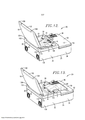
[0023] A Figura 12 é uma perspectiva traseira da máquina deembalagem a vácuo mostrada nas Figuras 1 a 11, que mostra uma primeira bolsa de vácuo posicionada na máquina para uma operação de embalagem em câmara em que uma bolsa de vácuo está localizada inteiramente na câmara de vácuo; e[0023] Figure 12 is a rear perspective of the vacuum packaging machine shown in Figures 1 to 11, showing a first vacuum bag positioned on the machine for a chamber packaging operation in which a vacuum bag is located entirely in the chamber vacuum; and
[0024] A Figura 13 é uma perspectiva posterior da máquina deembalagem a vácuo similar à Figura 12, mas que mostra uma segunda bolsa de vácuo posicionada na máquina para uma operação de embalagem externa em que a segunda bolsa de vácuo se estende apenas parcialmente na câmara de vácuo.[0024] Figure 13 is a rear view of the vacuum packaging machine similar to Figure 12, but showing a second vacuum bag positioned on the machine for an outer packaging operation in which the second vacuum bag extends only partially into the chamber of vacuum.
[0025] Os desenhos não limitam a presente invenção àsmodalidades específicas reveladas e descritas no presente documento. Os desenhos não estão necessariamente em escala, mas sim, é dada ênfase à clara ilustração dos princípios da modalidade preferencial.[0025] The drawings do not limit the present invention to the specific embodiments disclosed and described herein. The drawings are not necessarily to scale, but rather, emphasis is placed on clear illustration of the principles of the preferred modality.
[0026] Voltando-se inicialmente para as Figuras 1 e 2, uma máquinade embalagem a vácuo de combinação 20 é construída de acordo com uma modalidade preferencial da presente invenção. De preferência, a máquina ilustrada 20 usa bolsas de vácuo B1,B2 (vide Figuras 12 e 13) para embalar itens a vácuo tanto em um modo de operação de embalagem em câmara ou em um modo de operação de embalagem externa.[0026] Turning initially to Figures 1 and 2, a combination
[0027] As bolsas de vácuo B1,B2 são convencionais e cada umainclui painéis de bolsa opostos que são fixados à mesa e sobrepõem entre si. A bolsa de vácuo B1 é configurada primariamente para a operação de embalagem em câmara e inclui painéis que apresentam ambos, de preferência, superfícies interiores lisas. Conforme será observado, a bolsa B1 também pode ser usada para a operação de embalagem externa, embora os painéis lisos da bolsa B1 possam resultar na margem aberta da bolsa B1 seja fechada por aperto pela tampa da máquina 20 durante esvaziamento. Entretanto, sabe-se que uma bolsa de vácuo convencional, com painéis lisos e um inserto texturizado posicionado entre os painéis, pode ser usada para embalagem externa devido ao fato de o inserto apresentar pelo menos uma superfície texturizada que restringe que a margem aberta da bolsa seja fechada por pinçamento pela tampa.[0027] The B1,B2 vacuum bags are conventional and each includes opposing bag panels that are fixed to the table and overlap each other. Vacuum bag B1 is configured primarily for chamber packaging operation and includes panels which both preferably have smooth interior surfaces. As will be noted, pouch B1 can also be used for the outer packaging operation, although the smooth panels of pouch B1 may result in the open edge of pouch B1 being closed by squeezing by the lid of
[0028] A bolsa de vácuo B2 é configurada primariamente para aoperação de embalagem externa, e inclui um painel que apresenta uma superfície interior lisa e outro painel que apresenta uma superfície interior texturizada (não mostrada). Durante a operação de embalagem externa, será entendido que a superfície interior texturizada é projetada para restringir que a margem aberta da bolsa B2 seja fechada por prinçamento pela tampa da máquina 20 durante esvaziamento. Entretanto, a bolsa B2 também pode ser usada para a operação de embalagem em câmara para embalar itens a vácuo.[0028] The vacuum bag B2 is configured primarily for the outer packaging operation, and includes one panel that features a smooth inner surface and another panel that features a textured inner surface (not shown). During the outer packaging operation, it will be understood that the textured interior surface is designed to restrict the open edge of pouch B2 from being pried shut by the lid of the
[0029] Embora as bolsas de vácuo B1,B2 sejam descritas para uscom a máquina 20, será observado que outras bolsas de vácuo podem ser usadas sem se afastar do escopo da presente invenção. Por exemplo, conforme discutido acima, uma bolsa alternativa pode incluir um inserto texturizado para restringir que a margem aberta da bolsa seja fechada por prinçamento.[0029] Although vacuum bags B1,B2 are described for use with
[0030] No modo de embalagem em câmara, a máquina 20 operacomo um sistema de embalagem a vácuo em câmara para embalar a vácuo um ou mais itens (não mostrados) na bolsa de vácuo B1 (vide Figura 12). Ou seja, no modo de embalagem em câmara, toda a bolsa de vácuo B1 e o conteúdo da mesma (não mostrado) estão localizados inteiramente dentro de uma câmara de vácuo 22 da máquina 20 durante a esvaziamento da bolsa de vácuo B1.[0030] In the chamber packaging mode, the
[0031] No modo de embalagem externa, a máquina 20 opera comouma máquina de embalagem a vácuo externa para embalar um ou mais itens a vácuo (não mostrados) na bolsa de vácuo B2 (vide Figura 13). Ou seja, no modo de embalagem externa, a bolsa de vácuo se estende apenas parcialmente na câmara de vácuo 22 para que parte da bolsa de vácuo B2 esteja localizada dentro da câmara de vácuo 22, com o restante da bolsa B2 e o conteúdo da mesma (não mostrado) estando localizados fora da câmara de vácuo 22.[0031] In outer packaging mode,
[0032] Conforme usado no presente documento, o termo"esvaziamento" se refere, de preferência, à remoção de substancialmente todo o ar dentro da câmara de vácuo 22 e dentro da bolsa de vácuo. Com mais preferência, a "esvaziamento"não inclui a remoção de qualquer conteúdo da bolsa de vácuo que não seja ar. O termo "vácuo"se refere a um espaço que tenha sido pelo menos parcialmente esvaziado de ar com o uso de uma bomba de vácuo.[0032] As used herein, the term "emptying" preferably refers to the removal of substantially all of the air within the
[0033] Similar a sistemas convencionais de embalagem a vácuo, amáquina 20 é usada tipicamente para embalar a vácuo vários gêneros alimentícios (em forma sólida e/ou líquida). Entretanto, está dentro do escopo da presente invenção que a máquina 20 é implantada para embalar itens a vácuo (em forma sólida e/ou líquida) que não sejam gêneros alimentícios. A máquina ilustrada 20 inclui amplamente um alojamento 24, um sistema de esvaziamento 26 e um sistema de vedação de bolsa 28.[0033] Similar to conventional vacuum packaging systems, the
[0034] Voltando-se para as Figuras 1 a 6, o alojamento ilustrado 24inclui, de preferência, um gabinete 30, um recipiente a vácuo 32 sustentado pelo gabinete 30, e uma montagem de prateleira acondicionável 34 montada de modo comutável no gabinete 30.[0034] Turning to Figures 1 to 6, the illustrated
[0035] O gabinete retratado 30 inclui uma base de gabinete moldada 36, uma cobertura de acesso 38 e pés 40. A base de gabinete 36 inclui uma parede mais inferior 42 e paredes verticais 44 formadas integralmente com a parede mais inferior 42 (videFiguras 5 e 6). As paredes 42,44 formam, de modo cooperativo, os compartimentos interiores 46,48 que recebem outros elementos da máquina 20 (vide Figura 5).[0035] The pictured
[0036] A cobertura de acesso 38 inclui um corpo 50, uma orlaexterna 52, e uma interface de operador eletrônica 54 (vide Figuras 1, 2 e 5). Da maneira comum, a interface de operador 54 inclui um visor de LED 56 e múltiplos comutadores 58 para que um usuário controle a operação da máquina 20 (vide Figura 2. A interface de operador 54 é conectada de modo operacional a um controlador 60 da máquina 20 (vide Figura 5. A cobertura de acesso 38 é presa de modo removível à base de gabinete de modo a cobrir o compartimento interior 46. A cobertura de acesso 38 também apresenta uma superfície de sustentação de bolsa 61 que é particularmente configurada para receber a bolsa de vácuo B2 e qualquer conteúdo durante a operação de embalagem externa (vide, por exemplo, Figura 13).[0036] The access cover 38 includes a
[0037] A base de gabinete 36 e a cobertura de acesso 38, cadauma, de preferência, incluem um material de resina sintética que é moldado para formar uma estrutura rígida. Entretanto, está dentro do escopo da presente invenção que a base de gabinete 36 e a cobertura de acesso 38 incluem um ou mais materiais alternativos (por exemplo, aço inoxidável, alumínio, etc.).[0037] The
[0038] Voltando-se para as Figuras 1 a 5, a montagem de prateleira34 está, de preferência, na forma de uma bandeja dobrável externamente e é posicionável em uma condição de sustentação de bolsa (vide Figuras 2 a 4), na qual a montagem de prateleira 34 é adequada especialmente para sustentar a bolsa de vácuo B2 e o conteúdo contido na mesma antes, durante e/ou após a bolsa de vácuo B2 ser esvaziada e vedada. Caso desejado, a montagem de prateleira 34 também pode ser usada para sustentar a bolsa B1 antes e após operações de embalagem em câmara. A montagem de prateleira 34 inclui, de preferência, uma perna de sustentação 62 e um topo de prateleira 64 fixados ao gabinete 30. A perna de sustentação ilustrada 62 inclui um painel geralmente plano, pinos de dobradiça 66, um rebordo 68 que se estende entre os pinos de dobradiça 66, e projeções 70 (vide Figuras 3 e 4 ). O topo de prateleira 64 inclui, de preferência, um painel geralmente plano, pinos de dobradiça 72, presilhas 74, abas de dobradiça 76, e conectores de trava 78. O topo de prateleira 64 apresenta uma face de sustentação de bolsa 79 que se estende, de modo geral, a partir da superfície de sustentação de bolsa 61 quando a montagem de prateleira 34 estiver na condição de sustentação de bolsa (vide Figura 3. Na condição de sustentação de bolsa, a superfície de sustentação de bolsa 61 e a face de sustentação de bolsa 79 podem cooperar para sustentar parcialmente a bolsa de vácuo B2 (por exemplo, durante a operação de embalagem externa).[0038] Turning to Figures 1 to 5, the
[0039] Embora a perna de sustentação 62 e o topo de prateleira 64,ambos, de preferência, compreendam painéis unitários contínuos, está dentro do escopo da presente invenção que a perna 62 e o topo 64 sejam conformados de modo alternativo.[0039] Although the
[0040] A perna de sustentação 62 e o topo de prateleira 64 sãofixados de modo pivotante entre si inserindo-se os pinos de dobradiça 66 nas abas de dobradiça 76 para formar juntas de dobradiça 80. As juntas de dobradiça 80 permitem que a perna de sustentação 62 seja oscilada em relação ao topo de prateleira 64 entre uma posição dobrada (vide Figuras 1 e 5) e uma posição desdobrada (vide Figuras 2 a 4). Na posição dobrada, as presilhas 74 se engatam de modo liberável e agarram as projeções 70 e restringem que as projeções 70 sejam movidas para fora de engate com as presilhas 74. À medida que a perna de sustentação 62 é oscilada para a posição dobrada, as presilhas 74 e as projeções 70 se encaixam em engate. De modo similar, à medida que a perna de sustentação 62 é oscilada para fora da posição dobrada, as presilhas 74 e projeções 70 de desencaixam do engate. Quando a perna de sustentação 62 é desdobrada, o rebordo 68 se engata, de preferência, a uma margem externa do topo de prateleira 64 para restringir o pivotamento adicional da perna de sustentação para além da posição desdobrada (vide Figura 4).The
[0041] O topo de prateleira 64 também é fixado de modo pivotanteao gabinete 30 inserindo-se os pinos de dobradiça 72 nas aberturas de dobradiça (não mostradas) apresentadas pelo gabinete 30 para formar juntas de dobradiça 82. O topo de prateleira 64 pivota em relação ao gabinete 30 entre uma posição retraída (vide Figuras 1 e 5) e uma posição estendida (vide Figuras 2 a 4). Dessa forma, quando o topo de prateleira 64 é estendido e a perna de sustentação 62 é desdobrada para se engatar a uma superfície de trabalho (não mostrada), a montagem de prateleira 34 é instalada na condição de sustentação de bolsa, e pode receber pelo menos parte das bolsas de vácuo, conforme observado acima.
[0042] Quando a perna de sustentação 62 é oscilada para a posiçãodobrada, a perna de sustentação 62 e o topo de prateleira 64 podem, ambos, ser pivotados para a posição retraída (vide Figura 5). Na posição retraída, os conectores de trava 78 são presos de modo removível às travas 84 montadas no gabinete 30. Cada trava 84 inclui um alojamento 86 e um par de dedos 88 (vide Figuras 3 e 4). Os dedos 88 deslizam para o alojamento 86 na posição retraída para prender o conector de trava correspondente 78 em relação ao alojamento 86. Os dedos 88 são deslizáveis para fora do alojamento 86 a partir da posição retraída para uma posição de liberação em que o conector de trava 78 pode ser encaixado ou desencaixado de modo seletivo com os dedos 88 (vide Figuras 3 e 4 ).[0042] When the
[0043] Embora a estrutura ilustrada da montagem de prateleira 34seja preferencial, está dentro do escopo da presente invenção que os componentes da montagem de prateleira 34 sejam estruturados e/ou configurados alternativamente para operar. Por exemplo, em vez de se desdobrar a partir da posição retraída, a perna de sustentação 62 e o topo de prateleira 64 podem ser construídos para se transladar para fora da posição retraída, em que a perna de sustentação 62 e o topo de prateleira 64 residem dentro de um bolso apresentado dentro do gabinete.[0043] While the illustrated structure of the
[0044] Voltando-se para as Figuras 5 a 7, o recipiente a vácuo 32define a câmara de vácuo 22, que recebe, pelo menos parcialmente, a bolsa de vácuo B1,B2 para permitir a esvaziamento e a vedação da bolsa de vácuo B1,B2. Será observado que a câmara de vácuo 22 também pode receber uma seção de material tubular de bolsa de vácuo (não mostrado) para permitir a vedação de uma extremidade da seção sem esvaziar a seção (por exemplo, quando ambas as extremidades da seção são inicialmente abertas).[0044] Turning to Figures 5 to 7, the
[0045] O recipiente a vácuo 32 inclui, de preferência, um tabuleirode recipiente 90, a tampa de recipiente 92, uma vedação compressível alongada 94, e uma braçadeira de bolsa 96. Conforme será discutido, a tampa 92 é fixada de modo comutável ao tabuleiro 90 e é móvel entre uma posição aberta (vide Figura 2), que permite acesso à câmara de vácuo 22 e uma posição fechada (vide Figura 1), que permite que o ar dentro da câmara de vácuo 22 seja esvaziado. O tabuleiro 90, a tampa 92, e a vedação 94 de modo cooperativo a partir da câmara de vácuo 22.[0045]
[0046] Novamente com referência às Figuras 5 a 7, o sistema de esvaziamento 26 opera para remover ar da câmara de vácuo 22 de modo seletivo para esvaziar a bolsa de vácuo B1,B2. O sistema de esvaziamento 26 inclui, de preferência, uma bomba de vácuo 98, um encaixe de tubulação 100 que define uma porta de vácuo 102 dentro da câmara 22, e uma linha de vácuo (não mostrada) que conecta de modo fluido a bomba de vácuo 98 e a porta de vácuo 102 (vide Figura 5). A bomba de vácuo 98 é operável para retirar ar da câmara de vácuo 22 por meio da linha de vácuo e da porta de vácuo 102.[0046] Again with reference to Figures 5 to 7, the emptying system 26 operates to remove air from the
[0047] O sistema de vedação de bolsa 28 é configurado, depreferência, para fechar uma margem aberta M (vide Figuras 12 e 13) da bolsa de vácuo B1,B2 fundindo-se os painéis de bolsa P entre si ao longo de uma linha de vedação que se estende lateralmente (não mostrada). O sistema de vedação de bolsa 28 inclui, de preferência, um par de cilindros pneumáticos 104 e uma barra de vedação 106 (vide Figuras 5 a 7).[0047] The
[0048] Os cilindros ilustrados 104 são operáveis, de preferência,para elevar e baixar a barra de vedação 106 em relação ao recipiente a vácuo 32 e transmitir uma corrente elétrica através da barra de vedação 106. Cada cilindro 104 inclui, de preferência, um alojamento de cilindro 108 e um pistão alongado 110 (vide Figura 7). Cada alojamento de cilindro 108 sustenta uma porta de vácuo 112 e a extremidade de um condutor elétrico 114. O alojamento de cilindro 108 apresenta uma câmara de cilindro (não mostrada) que recebe de modo deslizante o pistão 110. O alojamento de cilindro 108 inclui, de preferência, um material de resina sintética moldado, embora o alojamento de cilindro 108 possa incluir outros materiais.[0048] The illustrated
[0049] O pistão 110 inclui, de preferência, um material de metaleletricamente condutor e, com mais preferência, é feito de latão. Essa construção permite que o cilindro 104 transmita uma corrente elétrica entre a barra de vedação 106 e o respectivo condutor elétrico 114. Entretanto, o pistão 110 pode incluir outros materiais.[0049] The
[0050] A câmara de cilindro está em comunicação fluida com abomba de vácuo por meio da porta de vácuo 112 e linhas de vácuo (não mostradas) para que a porção da câmara de cilindro acima do pistão possa ter ar esvaziado de modo seletivo. Esvaziando-se o ar da câmara de cilindro, o pistão 110 é forçado a se mover para cima, fora por cima do alojamento de cilindro 108. De modo similar, permitindo-se que o ar retorne à câmara de cilindro acima do pistão 110, o pistão 110 é movido para baixo para o alojamento de cilindro 108. Portanto, a pressão a vácuo é abastecida de modo seletivo aos cilindros 104 quando for desejado começar o processo de vedação de bolsa.[0050] The cylinder chamber is in fluid communication with the vacuum pump via the
[0051] Da maneira comum, a barra de vedação 106 é operável parafechar por vedação de modo seletivo a margem aberta M da bolsa de vácuo B1,B2. A barra de vedação 106 inclui, de preferência, entre outras coisas, uma viga alongada 116, uma tira de metal condutor 118 sustentada ao longo da margem de topo da viga 116, e um par de conectores de metal 120 que apresentam soquetes 122 (vide Figura 5). Os soquetes 122 são conformados em forma de cilindro e se projetam verticalmente dentro dos conectores de metal 120. Os soquetes 122 são dimensionados e configurados para receber de modo deslizante os pistões 110.[0051] In the ordinary way, the sealing
[0052] Os conectores de metal 120 que apresentam os soquetes 122 são fixados às respectivas extremidades da tira de metal 118. A tira de metal 118 é configurada para transmitir corrente elétrica entre os conectores 120 e, desse modo, gerar calor suficiente para vedar a margem aberta M. Entretanto, está dentro do âmbito da presente invenção que a barra de vedação 106 seja configurada de modo alternativo.[0052] The metal connectors 120 having the
[0053] Com a barra de vedação 106 montada nos pistões 110, ospistões 110 podem ser comutados ao mesmo tempo para mover a barra de vedação 106 para cima em relação ao tabuleiro de recipiente 90 para serem postos em engate com uma tira de vedação 124 da tampa 92 (vide Figuras 5 e 6). De modo similar, os pistões 110 podem ser comutados ao mesmo tempo para mover a barra de vedação 106 para baixo em relação ao tabuleiro de recipiente 90 e ao espaço da barra de vedação 106 abaixo da tira de vedação 124.[0053] With the sealing
[0054] Voltando-se para as Figuras 2 e 5 a 13, o tabuleiro derecipiente 90 compreende, de preferência, um tabuleiro unitário, e inclui um assoalho 126, uma orla externa 128, e uma parede lateral 130 que interconecta o assoalho 126 e a orla 128. O tabuleiro 90 inclui adicionalmente um par de alojamentos de dobradiça separados 132 e um par de batentes 134 sustentados pelos corpos de dobradiça 132 (vide Figuras 10 a 13).[0054] Turning to Figures 2 and 5 to 13, the
[0055] O tabuleiro 90 também apresenta um topo aberto 136circundado pela orla externa 128 e uma face de vedação de recipiente voltada para cima 138 (vide Figuras 2 e 7). A câmara de vácuo 22 se projeta para o tabuleiro 90 a partir do topo aberto 136 e apresenta uma dimensão de comprimento máximo Ld, uma dimensão de largura máxima Wd, e uma dimensão de profundidade máxima Dd (vide Figuras 2 e 5). A dimensão de comprimento máximo Ld varia, de preferência, de cerca de dez centímetros (10 cm) até cerca de trinta centímetros (30 cm), e, com mais preferência, tem cerca de dezoito centímetros (18 cm). A dimensão de largura máxima Wd varia, de preferência, de cerca de dez centímetros (10 cm) até cerca de cinquenta centímetros (50 cm), e, com mais preferência, tem cerca de trinta e cinco centímetros (35 cm). A dimensão de profundidade máxima Dd varia, de preferência, de cerca de cinco centímetros (5 cm) até cerca de trinta centímetros (30 cm), e, com mais preferência, tem cerca de dez centímetros (10 cm).[0055]
[0056] Caso desejado, a câmara 22 não precisa ter formatoretangular, já que outros formatos e tamanhos adequados estão dentro do âmbito da presente invenção. Por exemplo, a câmara 22 pode ser dimensionada alternativamente para corresponder especificamente ao formato e ao tamanho do item a ser vedado na bolsa. Além disso, a câmara 22 é dimensionada e configurada de forma importante para embalar as operações de embalagem em câmara desejadas.[0056] If desired, the
[0057] Conforme será discutido, a face de vedação 138 éconfigurada para ser engatada pela vedação 94. De preferência, a face de vedação de recipiente ilustrada 138 é apresentada pela estrutura rígida da orla externa 128. Essa configuração permite que a vedação 94 seja posta em engate firme com a face de vedação de recipiente 138. Também, a face de vedação de recipiente 138 é, de preferência, substancialmente plana para fornecer engate contínuo entre a face de vedação de recipiente 138 e a vedação 94.[0057] As will be discussed, the sealing
[0058] Entretanto, o tabuleiro de recipiente 90 pode ser conformadoalternativamente e/ou configurado para ser posto em engate por vedação com a tampa 92. Por exemplo, a face de vedação de recipiente 138 pode apresentar um formato não plano (por exemplo, em que a face de vedação de recipiente 138 é definida por uma ou mais projeções, cristas, canais e/ou ondulações posicionadas ao longo do comprimento da orla 128). Em outra modalidade alternativa, o tabuleiro de recipiente 90 pode incluir uma vedação produzível alongada (por exemplo, similar para vedar 94) que se engata e é deformada pela tampa 92 quando a tampa 92 for fechada. O tabuleiro de recipiente ilustrado 90 é montado, de preferência, ao gabinete 30 para que o tabuleiro 30 e o gabinete 30 forneçam, forneçam, de modo cooperativo, uma base 139, com o tabuleiro 90 se projetando para o compartimento 48.[0058] Meanwhile, the
[0059] Voltando-se para as Figuras 2, 5, 6, e 9 a 11, a tampa derecipiente 92 é alongada para apresentar extremidades de tampa osciláveis e articuladas 140,142 (vide Figuras 10 e 11). A tampa 92 é fixada, de preferência, de modo comutável ao tabuleiro 90 adjacente à extremidade articulada 142 para se mover entre a posição aberta e a posição fechada. De preferência, a tampa 92 tem uma construção rígida e inclui um corpo de tampa 144, pinos de dobradiça 146 e a tira de vedação 124.[0059] Turning to Figures 2, 5, 6, and 9 to 11, the
[0060] O corpo de tampa 144 é, de preferência, rígido, e inclui umparede superior 150, uma orla externa 152, nervuras interiores de reforço 154, manípulos 156, e uma parede de montagem interior 158, que são formados integralmente entre si (vide Figuras 2, 5 e 6). A parede superior 150 define, de preferência, um formato externo convexo geralmente contínuo da tampa 92, embora a tampa 92 possa ser formada de várias maneiras. As nervuras 154 se estendem ao longo de uma superfície interior da parede superior 150, e interconectam a orla externa 152 e a parede superior 150 uma à outra para reforçar a tampa 92. A parede de montagem 158 se estende, de preferência, lateralmenteao longo da superfície interior da parede superior 150, e recebe esustenta a tira de vedação 124.[0060] The
[0061] A tampa 92 de preferência amplia o topo aberto 136 dotabuleiro de recipiente 90 quando a tampa 92 estiver na posiçãofechada. A parede superior 150, a orla 152 e os manípulos 156 apesentam, de modo cooperativo, uma superfície exterior convexa da tampa 92. Os manípulos ilustrados 156 estão localizados adjacentes à extremidade oscilável 140 da tampa 92, e formam os respectivos cantos da tampa 92. A orla externa 152 e o corpo de tampa 144 apresentam, de modo cooperativo, aberturas de canto recuadas 160 localizadas adjacentes à extremidade articulada 142 da tampa 92 (vide Figuras 2, 10 e 11). Também, a orla externa 152 apresenta, de preferência, um sulco 162 e uma face de vedação de orla 164 que se estendem sem fim para receber a vedação 94 (vide Figura 8).[0061] The
[0062] De preferência, o corpo de tampa 144 inclui adicionalmenteum par de batentes 166 que se projetam a partir das respectivas porções da orla externa 152 (vide Figuras 9 a 11). Na modalidade ilustrada, cada batente 166 compreende uma aba geralmente retangular que apresenta uma superfície de extremidade mais externa 168. Cada batente 166 tem, de preferência, um formato geralmente retangular e plano, de modo que o batente 166 apresenta superfícies laterais paralelas 169 que se estendem entre a superfície de extremidade 168 e a face de vedação de orla 164 (vide Figura 9. Também, o batente ilustrado 166 apresenta uma dimensão de altura de batente S medida entre a face de vedação de orla 164 e a superfície de extremidade 168 (vide Figura 8. A dimensão de altura de batente S varia, de preferência, de cerca de 0,03 centímetros (um centésimo de polegada (0,01")) até cerca de 1,27 centímetros (meia polegada (0,5")), e, com mais preferência, tem cerca de 0,39 centímetros (cento e cinquenta e cinco milésimos de polegada (0,155")).[0062] Preferably, the
[0063] Os batentes 166 definem, de modo cooperativo, uma fendaque se estende lateralmente T entre os mesmos. Conforme será discutido, a fenda T é configurada para receber a margem aberta M da bolsa de vácuo B2 durante a operação de embalagem externa.The
[0064] Para alguns aspectos da presente invenção, cada um dosbatentes 166 pode ter um formato e/ou uma configuração alternativos. Também, os batentes 166 podem ser posicionados alternativamente em relação à tampa 92. Por exemplo, embora os batentes ilustrados 166 se projetem, de preferência, para baixo a partir da face de vedação de orla 164, os batentes 166 podem se projetar para baixo a partir da adjacência da face de vedação de orla 164. Adicionalmente, a tampa 92 pode ter um número alternativo de batentes 166.[0064] For some aspects of the present invention, each of the
[0065] Também será observado que um ou mais dentre os batentes166 pode ser fornecido como parte do tabuleiro de recipiente 90 ou da vedação 94. Ainda adicionalmente, uma combinação de pelo menos dois dentre o tabuleiro de recipiente 90, a tampa 92, e a vedação 94 podem incluir, cada um, um ou mais batentes 166.[0065] It will also be noted that one or more of the
[0066] Os batentes 166 também podem ser configurados de modoalternativo sem que se afaste do espírito da presente invenção. Por exemplo, não é necessário que os batentes sejam formados como abas em formato retangular, ou ainda, que sejam conformados de modo similar. Por exemplo, os batentes 166 podem ser, alternativamente, corrugações, nervuras, ou outras projeções adequadas que limitam a compressão da vedação 94, conforme será descrito.[0066] The
[0067] O corpo de tampa 144 inclui, de preferência, um material deresina sintética que é moldado para formar uma construção de tampa rígida. Entretanto, está dentro do escopo da presente invenção que o corpo de tampa 144 inclua um ou mais materiais alternativos (por exemplo, aço inoxidável, alumínio, etc.).[0067] The
[0068] Os pinos de dobradiça 146 são presos ao corpo de tampa144 adjacentes à extremidade de tampa articulada 142, e se projetam lateralmente nas aberturas de canto 160. Os pinos de dobradiça 146 são montados de modo comutável dentro das aberturas fendidas 170 apresentadas pelo alojamento de dobradiça 132 para se formar juntas de dobradiça 172 (vide Figuras 10 e 11 ). De preferência, as juntas de dobradiça 172 montam de modo pivotante a tampa 92 ao tabuleiro de recipiente 90 para que a tampa 92 possa oscilar em relação ao tabuleiro 90 entre as posições aberta e fechada. Entretanto, as juntas de dobradiça ilustradas 172 também permitem, de preferência, que os pinos de dobradiça 146 deslizem verticalmente dentro das aberturas fendidas 170.[0068] Hinge pins 146 are secured to
[0069] Embora as juntas de dobradiça ilustradas 172 sejampreferenciais para montar de modo comutável a tampa 92 no tabuleiro 90, os princípios da presente invenção são aplicáveis onde um mecanismo alternativo é usado para montar a tampa 92. Por exemplo, os alojamentos de dobradiça 132 podem ser formados como parte da tampa 92 e os pinos de dobradiça 146 podem ser fornecidos como parte da base 139. Também, em vez de usar um par de dobradiças pivotantes, a máquina 20 pode incluir um acoplamento de quatro barras para montar de modo comutável a tampa 92 ao tabuleiro 90.[0069] While the illustrated
[0070] Na posição fechada, as superfícies de extremidade 168engatam a face de vedação de recipiente 138 para sustentar a tampa 92 em relação ao tabuleiro de recipiente 90 (vide Figura 11). Quando a tampa 92 estiver fechada, os pinos de dobradiça 146 estão localizados em uma posição mais inferior dentro das aberturas fendidas (vide Figura 11. Também na posição fechada, a face de vedação de orla 164 e a face de vedação de recipiente 138 se opõem uma à outra e são separadas para definir, de modo cooperativo, um vão de vedação 174. Conforme será discutido, a vedação 94 amplia o vão de vedação 174 e engata por vedação as faces de vedação 138,164 durante a esvaziamento da câmara de vácuo 22 e da bolsa de vácuo B1,B2.[0070] In the closed position, the end surfaces 168 engage the
[0071] Novamente, o recipiente a vácuo 32 inclui, de preferência, otabuleiro 90, a tampa 92 e a vedação 94, que formam, de modo cooperativo, a câmara de vácuo 22. Quando a tampa 92 estiver fechada, a vedação 94 amplia o vão de vedação 174, o que permite a esvaziamento da câmara de vácuo 22 e da bolsa de vácuo B1,B2.[0071] Again, the
[0072] A vedação 94 compreende, de preferência, uma estrutura devedação unitária contínua. A vedação ilustrada 94 inclui, de preferência, uma nervura de sustentação 176, uma seção de flange 178, e um rebordo 180 (vide Figura 8. A seção de flange 178 apresenta uma face de flange 182 que se engata à face de vedação de orla 164. De preferência, o rebordo 180 compreende uma tira de material com uma espessura geralmente constante. O rebordo 180 também se projeta, de preferência, a um ângulo A em relação à face de flange 182 (vide Figura 8. O ângulo A varia, de preferência, de cerca de dez graus (10°) até cerca de cinquenta graus (50°) e, com mais preferência, tem cerca de trinta graus (30°). Entretanto, o rebordo 180 pode ser dimensionado e/ou conformado de modo alternativo sem se afastar do escopo da presente invenção.[0072] The
[0073] A seção de flange 178 e rebordo 180 define, de modocooperativo, uma dimensão de altura de vedação L medida entre a face de flange 182 e uma borda184 do rebordo 180 (vide Figura 8. A dimensão de altura de vedação L varia, de preferência, entre cerca de 0,25 centímetros (um décimo de polegada (0,1")) e cerca de 1,27 centímetros (meia polegada (0,5")). Entretanto, está dentro do âmbito da presente invenção que a vedação L tenha um tamanho e/ou uma configuração alternativos.[0073] The
[0074] A vedação 94 inclui, de preferência, um material de resinasintética e, com mais preferência, inclui um material de silicone elástico. Entretanto, para alguns aspectos da presente invenção, a vedação 94 pode incluir outros materiais.[0074] The
[0075] Quando a tampa 92 estiver fechada, a vedação 94 éconfigurada para ampliar o vão de vedação 174 engatando-se por vedação as faces de vedação 138,164. Em particular, a face de flange 182 se engata à face de vedação de orla 164 e a borda 184 se engata à face de vedação de recipiente 138. Dessa forma, durante a esvaziamento da câmara de vácuo 22 e da bolsa de vácuo B1, B2, a vedação 94 restringe a entrada de ar na câmara de vácuo 22. Conforme será discutido, a vedação 94 e os batentes 166 são configurados para restringir que a bolsa de vácuo B2 seja fechada por prinçamento pela tampa 94 durante a operação da máquina 20 no modo de embalagem externa.[0075] When the
[0076] Novamente, a barra de vedação 106 é montada e comutávelpelos cilindros 104 para cima e para baixo em relação ao tabuleiro de recipiente 90 para ser posta em engate e em desengate com a tira de vedação 124 da tampa 92. A barra de vedação ilustrada 106 se estende substancialmente em paralelo a uma seção que se estende lateralmente da face de vedação de recipiente 138. Ao mesmo tempo, a barra de vedação 106 é separada do tabuleiro 90 para que o tabuleiro 90 não restrinja o movimento para cima e para baixo da barra de vedação.[0076] Again, the sealing
[0077] Voltando-se para as Figuras 5 a 7 e 12, a braçadeira de bolsailustrada 96 é operável para se agarrar de modo seletivo à margem aberta M da bolsa de vácuo B1 durante a esvaziamento da mesma no modo de embalagem em câmara. Ou seja, a braçadeira de bolsa 96 é projetada para se agarrar à margem aberta M da bolsa de vácuo B1 quando a bolsa de vácuo B1 estiver localizada inteiramente dentro da câmara de vácuo 22.[0077] Turning to Figures 5 to 7 and 12, the illustrated
[0078] A braçadeira de bolsa 96 inclui, de preferência, uma baseestacionária 186, um clipe deslizável 188 que é montado de modo deslizante na base 186, e uma ligação 190 que interconecta a base 186 e o clipe 188 (vide Figura 7). A base 186 inclui, de preferência, uma placa angulada com pilares verticais 192 e um par de postes separados 194.[0078] The
[0079] O clipe 188 é unitário e inclui um par de abas 196 (videFiguras 5 e 12), e apresenta aberturas fendidas (não mostradas). As aberturas recebem, de modo deslizante, os pilares 192 para permitir o movimento vertical do clipe 188 em relação à base 186. O clipe 188 é deslizável para cima e para baixo entre uma posição de pinçamento (vide Figuras 5 e 6), em que as abas 196 se engatam às extremidades superiores dos postes 194, e uma posição aberta (vide Figura 7), em que as abas 196 são separadas acima das extremidades superiores dos postes 194.
[0080] Para agarrar a margem aberta M da bolsa de vácuo B1, abraçadeira de bolsa 96 é posicionada inicialmente na posição aberta para que a braçadeira de bolsa 96 possa receber a margem aberta M. Com a margem aberta M localizada entre as abas 196 e os postes 194, a braçadeira de bolsa 96 pode ser comutada da posição aberta para a posição de pinçamento para agarrar a margem aberta M.[0080] To grip the open edge M of the vacuum bag B1, the
[0081] Quando a margem aberta M da bolsa de vácuo B1 foragarrada pela braçadeira de bolsa 96 na posição de pinçamento, a braçadeira de bolsa 96 restringe, de preferência, o movimento da margem aberta M em relação ao recipiente a vácuo 32. Com mais preferência, a braçadeira de bolsa 96 restringe o movimento lateral da margem aberta M em relação à barra de vedação 106. Como resultado, a braçadeira de bolsa 96 mantém a margem aberta M estável durante a esvaziamento e a vedação da bolsa de vácuo B1. Mantendo-se a margem aberta M estável, a braçadeira de bolsa 96 permite que a barra de vedação 106 forme uma linha de vedação hermética ao longo de toda a extensão lateral da margem aberta M.[0081] When the open edge M of the vacuum bag B1 has been gripped by the
[0082] Para liberar a braçadeira de bolsa 96 de engate porpinçagem com a margem aberta M da bolsa de vácuo B1, a braçadeira de bolsa 96 é comutada inicialmente da posição de pinçamento para a posição aberta. A bolsa de vácuo B1 pode, então, ser removida seletivamente da braçadeira de bolsa aberta 96.[0082] To release the
[0083] Voltando-se para as Figuras 8 a 11, a fenda T é configuradapara receber a margem aberta M da bolsa de vácuo B2 quando a tampa 92 estiver fechada e a máquina 20 for usada na operação de embalagem externa. A vedação 94 e os batentes 166 cooperam para restringir que a bolsa de vácuo B2 seja fechada por aperto pela tampa 96 durante a esvaziamento da bolsa de vácuo B2 no modo de embalagem externa. De preferência, a vedação 94 e os batentes 166 são dimensionados para que a dimensão de altura de vedação L seja maior que a dimensão de altura de batente S (vide Figura 8). Isso resulta em que a vedação 94 seja comprimida na posição fechada. Entretanto, a vedação 94 e os batentes 166 também são dimensionados, de preferência, para que a borda 184 da vedação 94 seja separada da seção de flange 178 na posição fechada. Ou seja, quando a tampa 92 estiver fechada, o rebordo 180, de preferência, não é flexionado em direção à seção de flange 178 para que a borda 184 da vedação 94 faça contato com a seção de flange 178.[0083] Turning to Figures 8 to 11, the slot T is configured to receive the open edge M of the vacuum bag B2 when the
[0084] A diferença percentual de tamanho da dimensão de altura devedação L sobre a dimensão de altura de batente S varia, de preferência, de cerca de cinquenta porcento (50%) até cerca de quatrocentos por cento (400%), e, com mais preferência, tem cerca de duzentos e cinquenta porcento (250%).[0084] The percentage difference in size of the inset height dimension L over the abutment height dimension S preferably ranges from about fifty percent (50%) to about four hundred percent (400%), and with most preferably, it is about two hundred and fifty percent (250%).
[0085] Em operação, a máquina de embalagem a vácuo 20 podeser usada para esvaziar e vedar bolsas de vácuo B1,B2 com seu conteúdo com o uso, respectivamente, do modo de operação de embalagem em câmara e do modo de operação de embalagem externa. Inicialmente, a bolsa de vácuo B1 e seu conteúdo são colocados inteiramente dentro da câmara de vácuo 22 da máquina de embalagem a vácuo 20 para a esvaziamento e a vedação com o uso do modo de operação de embalagem em câmara. A margem aberta M da bolsa de vácuo B1 é presa à braçadeira de bolsa 96. A tampa 92 é, então, fechada por oscilação para que a vedação 94 se engate à face de vedação de recipiente 138 (vide Figura 9). O usuário pode, então, começar a esvaziar a câmara de vácuo 22. Em alguns casos, a tampa 92 pode não estar na posição fechada antes de esvaziar a câmara 22 (vide, por exemplo, Figura 10, em que a porção da tampa 92 adjacente às juntas de dobradiça 172 não está totalmente fechada). Nesse caso, o processo de esvaziamento da câmara 22 faz com que a tampa 92 comute para baixo para a posição fechada (vide Figura 11).[0085] In operation, the
[0086] Durante o processo de esvaziamento de ar da câmara devácuo 22, a bolsa de vácuo B1 também é esvaziada através da margem aberta M da mesma. A margem aberta M da bolsa de vácuo B1 é fechada por vedação após a bolsa de vácuo B1 ter sido esvaziada. Durante o processo de vedação, a condição de vácuo dentro da câmara 22 é mantida, de preferência. Uma vez que o processo de vedação esteja completo, a máquina 20 ventila a câmara 22 para o ambiente para que o ar possa retornar à câmara 22.[0086] During the process of emptying air from the
[0087] Após ventilar a câmara de vácuo 22 para o ambiente, a bolsade vácuo vedada B1 e o conteúdo podem ser removidos da câmara de vácuo 22. Especificamente, o usuário primeiro oscila a tampa 92 para a posição aberta para conseguir acesso à câmara de vácuo. O usuário pode, então, remover a bolsa de vácuo vedada B1 e o conteúdo da câmara de vácuo 22.[0087] After venting the
[0088] Uma vez que a bolsa de vácuo B1 e o conteúdo tenham sidovedados e removidos da máquina 20, a operação de embalagem em câmara (com uma nova bolsa B1 e seu conteúdo) pode ser repetida, ou a bolsa de vácuo B2 e seu conteúdo podem ser colocados na máquina 20 para a esvaziamento e a vedação com o uso do modo de operação de embalagem externa. A bolsa de vácuo B2 está localizada apenas parcialmente dentro da câmara de vácuo 22 para que a margem aberta M da mesma esteja localizada dentro da câmara de vácuo. Além disso, o restante da bolsa de vácuo B2 e seu conteúdo são posicionados fora da câmara de vácuo 22 e sustentados no gabinete 30. Em particular, a superfície de sustentação de bolsa 61 da cobertura de acesso 38 é operável para sustentar a bolsa de vácuo B2 e seu conteúdo (por exemplo, vide Figura 13). Opcionalmente, a face de sustentação de bolsa 79 da montagem de prateleira 34 pode cooperar com a superfície de sustentação de bolsa 61 para receber e sustentar a bolsa de vácuo B2 junto com seu conteúdo.[0088] Once the vacuum bag B1 and its contents have been sealed and removed from the
[0089] Após colocar a bolsa de vácuo B2 e seu conteúdo, a tampa92 é, então, fechada por oscilação para que a vedação 94 se engate à face de vedação de recipiente 138 (vide Figura 9). A vedação 94 também se engata à parte da bolsa de vácuo B2 que se estende ao longo da face de vedação 138 e através da fenda T. Novamente, os batentes 166 cooperam com a vedação 94 para restringir que a tampa 92 feche a bolsa de vácuo B2 por compressão ao longo da face de vedação 138.[0089] After placing the vacuum bag B2 and its contents, the
[0090] Com a tampa 92 fechada por oscilação, o usuário pode,então, começar a esvaziar a câmara de vácuo 22. Novamente, se a tampa 92 não estiver na posição fechada antes do esvaziamento da câmara 22, o processo de esvaziamento da câmara 22 faz com que a tampa 92 comute para baixo para a posição fechada (vide Figura 11.[0090] With the
[0091] Durante o processo de esvaziamento de ar da câmara devácuo 22, a bolsa de vácuo B2 é esvaziada através da margem aberta M. Uma vez que a bolsa B2 seja esvaziada, a margem aberta M da bolsa de vácuo B2 é, então, fechada por vedação. Novamente, durante o processo de vedação, a condição de vácuo dentro da câmara 22 é mantida de preferência. Uma vez que o processo de vedação esteja completo, a máquina 20 ventila a câmara 22 para o ambiente para que o ar possa retornar à câmara 22. A bolsa de vácuo vedada B2 e o conteúdo podem, então, ser removidos da câmara de vácuo 22 abrindo- se a tampa 92.[0091] During the process of emptying air from the
[0092] Embora a operação de embalagem externa seja descritacomo ocorrendo após a operação de embalagem em câmara, os princípios da presente invenção são aplicáveis onde a operação de embalagem externa ocorre antes da operação de embalagem em câmara. Além disso, será observado que cada uma das múltiplas bolsas de vácuo pode ser esvaziada e vedada uma após a outra com o uso de uma das operações da máquina de embalagem a vácuo 20. Por exemplo, as etapas associadas à operação de embalagem externa podem ser repetidas múltiplas vezes em série para esvaziar e vedar múltiplas bolsas. De modo similar, as etapas associadas à operação de embalagem em câmara podem ser repetidas múltiplas vezes em série para esvaziar e vedar múltiplas bolsas. Também será observado que a máquina ilustrada 20 pode ser usada para esvaziar e vedar múltiplas bolsas de vácuo ao mesmo tempo (por exemplo, quando as margens abertas das bolsas estiverem separadas ao longo do comprimento da barra de vedação 106).[0092] Although the outer packaging operation is described as occurring after the chamber packaging operation, the principles of the present invention are applicable where the outer packaging operation occurs before the chamber packaging operation. In addition, it will be appreciated that each of the multiple vacuum bags can be emptied and sealed one after the other using one of the vacuum
[0093] Embora a descrição acima apresente recursos demodalidades preferenciais da presente invenção, outras modalidades preferenciais também podem ser criadas com a manutenção dos princípios da invenção. Tais outras modalidades preferenciais podem, por exemplo, ser dotadas de recursos retirados de uma ou mais dentre as modalidades descritas acima. Ainda adicionalmente, tais outras modalidades preferenciais podem incluir recursos de múltiplas modalidades descritas acima, particularmente, quando tais recursos forem compatíveis para uso conjunto apesar de terem sido apresentados independentemente como parte de modalidades separadas na descrição acima.[0093] Although the above description presents features of preferred embodiments of the present invention, other preferred embodiments can also be created with the maintenance of the principles of the invention. Such other preferred modalities may, for example, be endowed with resources drawn from one or more of the modalities described above. Still further, such other preferred embodiments may include features of multiple embodiments described above, particularly when such features are compatible for joint use even though they have been independently presented as part of separate embodiments in the above description.
[0094] As formas preferenciais da invenção descritas acima devemser usadas apenas como ilustração, e não devem ser utilizadas em um sentido limitante na interpretação do escopo da presente invenção. As modificações óbvias às modalidades exemplificativas, conforme estabelecido acima no presente documento, podem ser prontamente feitas pelas pessoas versadas na técnica sem que se afaste do espírito da presente invenção.[0094] The preferred forms of the invention described above are to be used for illustration only, and are not to be used in a limiting sense in interpreting the scope of the present invention. Obvious modifications to the exemplary embodiments as set forth herein above may readily be made by persons skilled in the art without departing from the spirit of the present invention.
[0095] Os presentes inventores declaram sua intenção de confiarna Doutrina de Equivalentes para determinar e avaliar o escopo moderadamente justo da presente invenção como pertencente a qualquer aparelho que não se desvie materialmente além do escopo literal da invenção conforme estabelecido nas reivindicações a seguir.[0095] The present inventors declare their intention to rely on the Doctrine of Equivalents to determine and evaluate the moderately fair scope of the present invention as pertaining to any apparatus that does not materially deviate beyond the literal scope of the invention as set forth in the following claims.
Claims (27)
Applications Claiming Priority (2)
| Application Number | Priority Date | Filing Date | Title |
|---|---|---|---|
| US201361869786P | 2013-08-26 | 2013-08-26 | |
| PCT/US2014/052771 WO2015031401A1 (en) | 2013-08-26 | 2014-08-26 | Combination chamber and external suction vacuum packaging machine |
Publications (2)
| Publication Number | Publication Date |
|---|---|
| BR112016003922A2 BR112016003922A2 (en) | 2017-08-01 |
| BR112016003922B1 true BR112016003922B1 (en) | 2021-09-08 |
Family
ID=52479113
Family Applications (1)
| Application Number | Title | Priority Date | Filing Date |
|---|---|---|---|
| BR112016003922-0A BR112016003922B1 (en) | 2013-08-26 | 2014-08-26 | COMBINATION CHAMBER AND VACUUM PACKAGING MACHINE BY EXTERNAL SUCTION AND METHOD TO EVACUATE AND SEALING VACUUM BAG |
Country Status (9)
| Country | Link |
|---|---|
| US (2) | US9708088B2 (en) |
| EP (1) | EP3038929B1 (en) |
| CN (1) | CN105873826B (en) |
| AU (1) | AU2014311278B2 (en) |
| BR (1) | BR112016003922B1 (en) |
| CA (1) | CA2922202C (en) |
| ES (1) | ES2689846T3 (en) |
| MX (2) | MX370601B (en) |
| WO (1) | WO2015031401A1 (en) |
Families Citing this family (10)
| Publication number | Priority date | Publication date | Assignee | Title |
|---|---|---|---|---|
| USD774577S1 (en) * | 2014-08-26 | 2016-12-20 | Hantover, Inc. | Combination vacuum packaging machine |
| CN107848645B (en) * | 2015-06-05 | 2021-05-11 | 光达家电用品公司 | Food storage device |
| IT201700098236A1 (en) * | 2017-09-01 | 2019-03-01 | Marziano Salvaro | VACUUM PACKAGING MACHINE. |
| CN107572039B (en) * | 2017-09-26 | 2020-02-14 | 福建元弘自动化科技有限公司 | Vacuum packaging device |
| IT201800004589A1 (en) * | 2018-04-17 | 2019-10-17 | VACUUM PACKAGING MACHINE, PARTICULARLY FOR DOMESTIC USE. | |
| US11714032B2 (en) * | 2019-03-22 | 2023-08-01 | Illinois Tool Works Inc. | Vacuum systems for epoxy mounting of material samples |
| CN111891448A (en) * | 2020-07-06 | 2020-11-06 | 黄山市胡兴堂桃花流水食品有限公司 | Stinky mandarin fish vacuum packaging machine |
| US20220227511A1 (en) * | 2021-01-20 | 2022-07-21 | William Cho | Vacuum chamber for sealing storage bags and accessories therefor |
| CN113212841A (en) * | 2021-04-20 | 2021-08-06 | 浙江小济生态农业有限公司 | Vacuum-pumping quick sealing equipment |
| EP4230539A3 (en) * | 2023-06-06 | 2024-02-14 | Webomatic Maschinenfabrik GmbH | Packaging machine for food or medical devices |
Family Cites Families (20)
| Publication number | Priority date | Publication date | Assignee | Title |
|---|---|---|---|---|
| JPS5159593A (en) * | 1974-11-21 | 1976-05-24 | Furukawa Seisakusho Kk | Shinkuhosohoho oyobisono shinkuhosoki |
| US4182095A (en) * | 1976-03-29 | 1980-01-08 | Day Timothy T | Packaging bulk commodities |
| IT1067343B (en) * | 1976-11-19 | 1985-03-16 | Bernardo P Di | METHOD AND DEVICE FOR THE VACUUM PACKAGING OF PRODUCTS |
| JPS601210B2 (en) * | 1981-05-23 | 1985-01-12 | 株式会社古川製作所 | automatic packaging machine |
| US4779398A (en) * | 1987-02-06 | 1988-10-25 | W. R. Grace & Co.-Conn., Cryovac Div. | Method and apparatus for making gas flushed packages |
| US5239808A (en) | 1992-05-13 | 1993-08-31 | Hantover, Inc. | Vacuum packaging machine |
| US5638664A (en) | 1995-07-17 | 1997-06-17 | Hantover, Inc. | Vacuum packaging apparatus |
| US5682727A (en) * | 1996-05-03 | 1997-11-04 | Koch Supplies, Inc. | Coupled cutting blade and heat element for use with vacuum packaging machinery |
| JPH11240507A (en) * | 1998-02-27 | 1999-09-07 | Toyo Jidoki Co Ltd | Transverse type vacuum packaging machine |
| RU2174936C2 (en) * | 1999-07-07 | 2001-10-20 | Акционерное общество открытого типа "Научно-исследовательский институт точного и электронного машиностроения" | Device for vacuum packing of articles into plastic bags |
| AU2001279192A1 (en) * | 2000-08-02 | 2002-02-13 | Koch Equipment Llc | Injection-molded vacuum packaging machine |
| ITMI20010270A1 (en) * | 2001-02-09 | 2002-08-09 | Germano Maina | MACHINE FOR VACUUM PACKAGING IN PLASTIC BAGS AND RIGID CONTAINERS |
| US20030159405A1 (en) * | 2002-02-28 | 2003-08-28 | Scott Knowlton | Vacuum packaging apparatus and method |
| US20050034427A1 (en) * | 2003-07-31 | 2005-02-17 | Landen Higer | Vacuum sealing system with a sealing element inside an evacuation chamber |
| US7146783B2 (en) | 2005-03-18 | 2006-12-12 | Hantover, Inc. | Vacuum packaging machine |
| USD536355S1 (en) | 2005-03-18 | 2007-02-06 | Hantover, Inc. | Vacuum packaging machine |
| TR200905557T1 (en) * | 2007-03-30 | 2009-12-21 | Arçeli̇k Anoni̇m Şi̇rketi̇ | A vacuum packaging device. |
| ES2339731B1 (en) * | 2008-06-05 | 2011-03-11 | Alfa Hogar, S.L. | DOMESTIC MACHINE TO PACK VACUUM PRODUCTS. |
| KR101529155B1 (en) | 2013-02-22 | 2015-06-16 | (주)상원 | apparatus for vacuum packing food vessel and plastic bag |
| US20150135641A1 (en) * | 2013-11-19 | 2015-05-21 | Zhihe Hu | Cavity-type vacuum sealing machine |
-
2014
- 2014-08-26 CA CA2922202A patent/CA2922202C/en active Active
- 2014-08-26 ES ES14839406.7T patent/ES2689846T3/en active Active
- 2014-08-26 US US14/469,375 patent/US9708088B2/en active Active
- 2014-08-26 EP EP14839406.7A patent/EP3038929B1/en active Active
- 2014-08-26 MX MX2016002439A patent/MX370601B/en active IP Right Grant
- 2014-08-26 BR BR112016003922-0A patent/BR112016003922B1/en active IP Right Grant
- 2014-08-26 CN CN201480058627.0A patent/CN105873826B/en active Active
- 2014-08-26 WO PCT/US2014/052771 patent/WO2015031401A1/en active Application Filing
- 2014-08-26 AU AU2014311278A patent/AU2014311278B2/en active Active
-
2016
- 2016-02-25 MX MX2019015253A patent/MX2019015253A/en unknown
-
2017
- 2017-07-17 US US15/651,635 patent/US10501219B2/en active Active
Also Published As
| Publication number | Publication date |
|---|---|
| US20150052850A1 (en) | 2015-02-26 |
| AU2014311278A1 (en) | 2016-03-17 |
| EP3038929A1 (en) | 2016-07-06 |
| EP3038929A4 (en) | 2017-05-10 |
| MX2016002439A (en) | 2016-06-24 |
| US10501219B2 (en) | 2019-12-10 |
| CA2922202C (en) | 2018-07-31 |
| CN105873826A (en) | 2016-08-17 |
| MX2019015253A (en) | 2020-02-07 |
| WO2015031401A1 (en) | 2015-03-05 |
| BR112016003922A2 (en) | 2017-08-01 |
| CA2922202A1 (en) | 2015-03-05 |
| MX370601B (en) | 2019-12-18 |
| AU2014311278B2 (en) | 2017-09-14 |
| CN105873826B (en) | 2018-04-06 |
| US20170313454A1 (en) | 2017-11-02 |
| EP3038929B1 (en) | 2018-07-04 |
| US9708088B2 (en) | 2017-07-18 |
| ES2689846T3 (en) | 2018-11-16 |
Similar Documents
| Publication | Publication Date | Title |
|---|---|---|
| BR112016003922B1 (en) | COMBINATION CHAMBER AND VACUUM PACKAGING MACHINE BY EXTERNAL SUCTION AND METHOD TO EVACUATE AND SEALING VACUUM BAG | |
| US7200974B2 (en) | Lidless vacuum appliance | |
| CN205615901U (en) | A test tube case that is used for liquid sample storage to transport | |
| US20140075889A1 (en) | System and method for storing items | |
| KR20140128772A (en) | apparatus for packing food vessel | |
| KR101160969B1 (en) | Vacuum packing apparatus | |
| KR101529155B1 (en) | apparatus for vacuum packing food vessel and plastic bag | |
| DE60310076D1 (en) | PACKING FOR TUBES | |
| CN208530967U (en) | A kind of bagger capable of rapid positioning | |
| KR20100004830U (en) | Plastic food container | |
| US10633157B2 (en) | Airtight container having deformable cover unit or deformable container unit | |
| CN210250678U (en) | Movable sealed disinfection cabinet | |
| KR101720209B1 (en) | Vacuum packing apparatus having pressure unit | |
| CN205915310U (en) | A tool holder for holding aerify tire patching device | |
| CN210871050U (en) | Cooking utensil | |
| CN207701316U (en) | A kind of inflator | |
| CN213263063U (en) | Food vacuum packaging device | |
| WO2013029563A1 (en) | Vacuum packing appliance | |
| US20110088571A1 (en) | Press for resealable zipper storage bags | |
| CN216735517U (en) | Plastic packaging box with protective structure | |
| JP2606264Y2 (en) | Deep drawing type packaging equipment | |
| CN207670815U (en) | Vacuum sealer | |
| KR101623842B1 (en) | Vacuum packing apparatus | |
| PT1524208E (en) | Kitchen furniture for housing a garbage container | |
| CN111453182A (en) | Vacuum storage device |
Legal Events
| Date | Code | Title | Description |
|---|---|---|---|
| B06U | Preliminary requirement: requests with searches performed by other patent offices: procedure suspended [chapter 6.21 patent gazette] | ||
| B06A | Patent application procedure suspended [chapter 6.1 patent gazette] | ||
| B09A | Decision: intention to grant [chapter 9.1 patent gazette] | ||
| B16A | Patent or certificate of addition of invention granted [chapter 16.1 patent gazette] |
Free format text: PRAZO DE VALIDADE: 20 (VINTE) ANOS CONTADOS A PARTIR DE 26/08/2014, OBSERVADAS AS CONDICOES LEGAIS. |