BR112015020606B1 - KIT FOR AN AEROSOL GENERATING SYSTEM - Google Patents
KIT FOR AN AEROSOL GENERATING SYSTEM Download PDFInfo
- Publication number
- BR112015020606B1 BR112015020606B1 BR112015020606-9A BR112015020606A BR112015020606B1 BR 112015020606 B1 BR112015020606 B1 BR 112015020606B1 BR 112015020606 A BR112015020606 A BR 112015020606A BR 112015020606 B1 BR112015020606 B1 BR 112015020606B1
- Authority
- BR
- Brazil
- Prior art keywords
- aerosol
- wall
- housing
- outlet
- ring
- Prior art date
Links
- 239000000443 aerosol Substances 0.000 title claims abstract description 115
- 239000000758 substrate Substances 0.000 claims abstract description 64
- 230000000391 smoking effect Effects 0.000 claims abstract description 26
- 229920002301 cellulose acetate Polymers 0.000 claims description 5
- 230000007246 mechanism Effects 0.000 claims description 4
- 230000015572 biosynthetic process Effects 0.000 claims description 3
- 238000010438 heat treatment Methods 0.000 description 54
- 239000007788 liquid Substances 0.000 description 43
- 239000000463 material Substances 0.000 description 28
- 239000003570 air Substances 0.000 description 16
- 238000003780 insertion Methods 0.000 description 9
- 230000037431 insertion Effects 0.000 description 9
- 238000003860 storage Methods 0.000 description 9
- XEEYBQQBJWHFJM-UHFFFAOYSA-N Iron Chemical compound [Fe] XEEYBQQBJWHFJM-UHFFFAOYSA-N 0.000 description 8
- -1 polypropylene Polymers 0.000 description 8
- DNIAPMSPPWPWGF-UHFFFAOYSA-N Propylene glycol Chemical compound CC(O)CO DNIAPMSPPWPWGF-UHFFFAOYSA-N 0.000 description 6
- 239000000919 ceramic Substances 0.000 description 6
- 235000019504 cigarettes Nutrition 0.000 description 6
- 230000009471 action Effects 0.000 description 5
- 239000012876 carrier material Substances 0.000 description 5
- 229910052751 metal Inorganic materials 0.000 description 5
- 239000002184 metal Substances 0.000 description 5
- PEDCQBHIVMGVHV-UHFFFAOYSA-N Glycerine Chemical compound OCC(O)CO PEDCQBHIVMGVHV-UHFFFAOYSA-N 0.000 description 4
- PXHVJJICTQNCMI-UHFFFAOYSA-N Nickel Chemical compound [Ni] PXHVJJICTQNCMI-UHFFFAOYSA-N 0.000 description 4
- 239000004743 Polypropylene Substances 0.000 description 4
- 229910045601 alloy Inorganic materials 0.000 description 4
- 239000000956 alloy Substances 0.000 description 4
- 239000012080 ambient air Substances 0.000 description 4
- 230000008901 benefit Effects 0.000 description 4
- 239000002131 composite material Substances 0.000 description 4
- 229910052742 iron Inorganic materials 0.000 description 4
- 230000000704 physical effect Effects 0.000 description 4
- 229920001155 polypropylene Polymers 0.000 description 4
- 230000000717 retained effect Effects 0.000 description 4
- OKTJSMMVPCPJKN-UHFFFAOYSA-N Carbon Chemical compound [C] OKTJSMMVPCPJKN-UHFFFAOYSA-N 0.000 description 3
- 229910052782 aluminium Inorganic materials 0.000 description 3
- XAGFODPZIPBFFR-UHFFFAOYSA-N aluminium Chemical compound [Al] XAGFODPZIPBFFR-UHFFFAOYSA-N 0.000 description 3
- 239000002775 capsule Substances 0.000 description 3
- 230000006835 compression Effects 0.000 description 3
- 238000007906 compression Methods 0.000 description 3
- 239000000835 fiber Substances 0.000 description 3
- 238000001914 filtration Methods 0.000 description 3
- 239000008263 liquid aerosol Substances 0.000 description 3
- 150000002739 metals Chemical class 0.000 description 3
- 229910001220 stainless steel Inorganic materials 0.000 description 3
- 239000010935 stainless steel Substances 0.000 description 3
- 229910052719 titanium Inorganic materials 0.000 description 3
- 239000010936 titanium Substances 0.000 description 3
- SNICXCGAKADSCV-JTQLQIEISA-N (-)-Nicotine Chemical compound CN1CCC[C@H]1C1=CC=CN=C1 SNICXCGAKADSCV-JTQLQIEISA-N 0.000 description 2
- LFQSCWFLJHTTHZ-UHFFFAOYSA-N Ethanol Chemical compound CCO LFQSCWFLJHTTHZ-UHFFFAOYSA-N 0.000 description 2
- PWHULOQIROXLJO-UHFFFAOYSA-N Manganese Chemical compound [Mn] PWHULOQIROXLJO-UHFFFAOYSA-N 0.000 description 2
- 241000208125 Nicotiana Species 0.000 description 2
- 235000002637 Nicotiana tabacum Nutrition 0.000 description 2
- 229910018487 Ni—Cr Inorganic materials 0.000 description 2
- 239000004696 Poly ether ether ketone Substances 0.000 description 2
- 239000004698 Polyethylene Substances 0.000 description 2
- RTAQQCXQSZGOHL-UHFFFAOYSA-N Titanium Chemical compound [Ti] RTAQQCXQSZGOHL-UHFFFAOYSA-N 0.000 description 2
- QCWXUUIWCKQGHC-UHFFFAOYSA-N Zirconium Chemical compound [Zr] QCWXUUIWCKQGHC-UHFFFAOYSA-N 0.000 description 2
- 230000002745 absorbent Effects 0.000 description 2
- 239000002250 absorbent Substances 0.000 description 2
- VNNRSPGTAMTISX-UHFFFAOYSA-N chromium nickel Chemical compound [Cr].[Ni] VNNRSPGTAMTISX-UHFFFAOYSA-N 0.000 description 2
- 229910017052 cobalt Inorganic materials 0.000 description 2
- 239000010941 cobalt Substances 0.000 description 2
- GUTLYIVDDKVIGB-UHFFFAOYSA-N cobalt atom Chemical compound [Co] GUTLYIVDDKVIGB-UHFFFAOYSA-N 0.000 description 2
- 235000011187 glycerol Nutrition 0.000 description 2
- 239000010439 graphite Substances 0.000 description 2
- 229910002804 graphite Inorganic materials 0.000 description 2
- 230000014759 maintenance of location Effects 0.000 description 2
- 229910052748 manganese Inorganic materials 0.000 description 2
- 239000011572 manganese Substances 0.000 description 2
- 229910001092 metal group alloy Inorganic materials 0.000 description 2
- 230000003278 mimic effect Effects 0.000 description 2
- 239000000203 mixture Substances 0.000 description 2
- 229910052759 nickel Inorganic materials 0.000 description 2
- 229960002715 nicotine Drugs 0.000 description 2
- SNICXCGAKADSCV-UHFFFAOYSA-N nicotine Natural products CN1CCCC1C1=CC=CN=C1 SNICXCGAKADSCV-UHFFFAOYSA-N 0.000 description 2
- 239000004033 plastic Substances 0.000 description 2
- 229920003023 plastic Polymers 0.000 description 2
- BASFCYQUMIYNBI-UHFFFAOYSA-N platinum Chemical compound [Pt] BASFCYQUMIYNBI-UHFFFAOYSA-N 0.000 description 2
- 229920003223 poly(pyromellitimide-1,4-diphenyl ether) Polymers 0.000 description 2
- 229920002530 polyetherether ketone Polymers 0.000 description 2
- 229920000573 polyethylene Polymers 0.000 description 2
- 239000007787 solid Substances 0.000 description 2
- 229910052715 tantalum Inorganic materials 0.000 description 2
- GUVRBAGPIYLISA-UHFFFAOYSA-N tantalum atom Chemical compound [Ta] GUVRBAGPIYLISA-UHFFFAOYSA-N 0.000 description 2
- 238000012546 transfer Methods 0.000 description 2
- WFKWXMTUELFFGS-UHFFFAOYSA-N tungsten Chemical compound [W] WFKWXMTUELFFGS-UHFFFAOYSA-N 0.000 description 2
- 229910052721 tungsten Inorganic materials 0.000 description 2
- 239000010937 tungsten Substances 0.000 description 2
- XLYOFNOQVPJJNP-UHFFFAOYSA-N water Substances O XLYOFNOQVPJJNP-UHFFFAOYSA-N 0.000 description 2
- 229910052726 zirconium Inorganic materials 0.000 description 2
- 229910000851 Alloy steel Inorganic materials 0.000 description 1
- VYZAMTAEIAYCRO-UHFFFAOYSA-N Chromium Chemical compound [Cr] VYZAMTAEIAYCRO-UHFFFAOYSA-N 0.000 description 1
- 229910001006 Constantan Inorganic materials 0.000 description 1
- GYHNNYVSQQEPJS-UHFFFAOYSA-N Gallium Chemical compound [Ga] GYHNNYVSQQEPJS-UHFFFAOYSA-N 0.000 description 1
- ZOKXTWBITQBERF-UHFFFAOYSA-N Molybdenum Chemical compound [Mo] ZOKXTWBITQBERF-UHFFFAOYSA-N 0.000 description 1
- 239000004642 Polyimide Substances 0.000 description 1
- 229920004933 Terylene® Polymers 0.000 description 1
- ATJFFYVFTNAWJD-UHFFFAOYSA-N Tin Chemical compound [Sn] ATJFFYVFTNAWJD-UHFFFAOYSA-N 0.000 description 1
- 238000009825 accumulation Methods 0.000 description 1
- 239000007961 artificial flavoring substance Substances 0.000 description 1
- YXTPWUNVHCYOSP-UHFFFAOYSA-N bis($l^{2}-silanylidene)molybdenum Chemical compound [Si]=[Mo]=[Si] YXTPWUNVHCYOSP-UHFFFAOYSA-N 0.000 description 1
- 238000009835 boiling Methods 0.000 description 1
- 229910052799 carbon Inorganic materials 0.000 description 1
- 229910010293 ceramic material Inorganic materials 0.000 description 1
- 229910052804 chromium Inorganic materials 0.000 description 1
- 239000011651 chromium Substances 0.000 description 1
- 235000019506 cigar Nutrition 0.000 description 1
- 210000000078 claw Anatomy 0.000 description 1
- 238000004140 cleaning Methods 0.000 description 1
- 238000004891 communication Methods 0.000 description 1
- 150000001875 compounds Chemical class 0.000 description 1
- 238000010276 construction Methods 0.000 description 1
- 230000008878 coupling Effects 0.000 description 1
- 238000010168 coupling process Methods 0.000 description 1
- 238000005859 coupling reaction Methods 0.000 description 1
- 238000005336 cracking Methods 0.000 description 1
- 238000013461 design Methods 0.000 description 1
- 238000001514 detection method Methods 0.000 description 1
- 229920001971 elastomer Polymers 0.000 description 1
- 238000005516 engineering process Methods 0.000 description 1
- 238000005530 etching Methods 0.000 description 1
- 239000000796 flavoring agent Substances 0.000 description 1
- 235000019634 flavors Nutrition 0.000 description 1
- 239000011888 foil Substances 0.000 description 1
- 235000013305 food Nutrition 0.000 description 1
- 229910052733 gallium Inorganic materials 0.000 description 1
- 229910052735 hafnium Inorganic materials 0.000 description 1
- VBJZVLUMGGDVMO-UHFFFAOYSA-N hafnium atom Chemical compound [Hf] VBJZVLUMGGDVMO-UHFFFAOYSA-N 0.000 description 1
- 230000006872 improvement Effects 0.000 description 1
- 230000001939 inductive effect Effects 0.000 description 1
- 238000002347 injection Methods 0.000 description 1
- 239000007924 injection Substances 0.000 description 1
- 239000011810 insulating material Substances 0.000 description 1
- 238000004519 manufacturing process Methods 0.000 description 1
- 239000000155 melt Substances 0.000 description 1
- 239000007769 metal material Substances 0.000 description 1
- 239000006262 metallic foam Substances 0.000 description 1
- 238000000034 method Methods 0.000 description 1
- 239000010445 mica Substances 0.000 description 1
- 229910052618 mica group Inorganic materials 0.000 description 1
- 229910052750 molybdenum Inorganic materials 0.000 description 1
- 239000011733 molybdenum Substances 0.000 description 1
- 229910021343 molybdenum disilicide Inorganic materials 0.000 description 1
- 229910052758 niobium Inorganic materials 0.000 description 1
- 239000010955 niobium Substances 0.000 description 1
- GUCVJGMIXFAOAE-UHFFFAOYSA-N niobium atom Chemical compound [Nb] GUCVJGMIXFAOAE-UHFFFAOYSA-N 0.000 description 1
- 229920001778 nylon Polymers 0.000 description 1
- 230000003287 optical effect Effects 0.000 description 1
- 244000052769 pathogen Species 0.000 description 1
- 239000000419 plant extract Substances 0.000 description 1
- 239000002984 plastic foam Substances 0.000 description 1
- 229910052697 platinum Inorganic materials 0.000 description 1
- 239000005020 polyethylene terephthalate Substances 0.000 description 1
- 229920001721 polyimide Polymers 0.000 description 1
- 239000011148 porous material Substances 0.000 description 1
- 239000000843 powder Substances 0.000 description 1
- 230000008569 process Effects 0.000 description 1
- 230000001007 puffing effect Effects 0.000 description 1
- 230000004044 response Effects 0.000 description 1
- 239000005060 rubber Substances 0.000 description 1
- 239000004065 semiconductor Substances 0.000 description 1
- 229910010271 silicon carbide Inorganic materials 0.000 description 1
- 239000000779 smoke Substances 0.000 description 1
- 239000000243 solution Substances 0.000 description 1
- 239000002904 solvent Substances 0.000 description 1
- 229910000601 superalloy Inorganic materials 0.000 description 1
- 229920001169 thermoplastic Polymers 0.000 description 1
- 239000004416 thermosoftening plastic Substances 0.000 description 1
- 229910052718 tin Inorganic materials 0.000 description 1
- 239000006200 vaporizer Substances 0.000 description 1
Images

Classifications
-
- H—ELECTRICITY
- H01—ELECTRIC ELEMENTS
- H01F—MAGNETS; INDUCTANCES; TRANSFORMERS; SELECTION OF MATERIALS FOR THEIR MAGNETIC PROPERTIES
- H01F27/00—Details of transformers or inductances, in general
- H01F27/006—Details of transformers or inductances, in general with special arrangement or spacing of turns of the winding(s), e.g. to produce desired self-resonance
-
- A—HUMAN NECESSITIES
- A24—TOBACCO; CIGARS; CIGARETTES; SIMULATED SMOKING DEVICES; SMOKERS' REQUISITES
- A24F—SMOKERS' REQUISITES; MATCH BOXES; SIMULATED SMOKING DEVICES
- A24F40/00—Electrically operated smoking devices; Component parts thereof; Manufacture thereof; Maintenance or testing thereof; Charging means specially adapted therefor
- A24F40/40—Constructional details, e.g. connection of cartridges and battery parts
-
- H—ELECTRICITY
- H01—ELECTRIC ELEMENTS
- H01F—MAGNETS; INDUCTANCES; TRANSFORMERS; SELECTION OF MATERIALS FOR THEIR MAGNETIC PROPERTIES
- H01F38/00—Adaptations of transformers or inductances for specific applications or functions
- H01F38/14—Inductive couplings
-
- H—ELECTRICITY
- H02—GENERATION; CONVERSION OR DISTRIBUTION OF ELECTRIC POWER
- H02J—CIRCUIT ARRANGEMENTS OR SYSTEMS FOR SUPPLYING OR DISTRIBUTING ELECTRIC POWER; SYSTEMS FOR STORING ELECTRIC ENERGY
- H02J50/00—Circuit arrangements or systems for wireless supply or distribution of electric power
- H02J50/10—Circuit arrangements or systems for wireless supply or distribution of electric power using inductive coupling
- H02J50/12—Circuit arrangements or systems for wireless supply or distribution of electric power using inductive coupling of the resonant type
-
- H—ELECTRICITY
- H02—GENERATION; CONVERSION OR DISTRIBUTION OF ELECTRIC POWER
- H02J—CIRCUIT ARRANGEMENTS OR SYSTEMS FOR SUPPLYING OR DISTRIBUTING ELECTRIC POWER; SYSTEMS FOR STORING ELECTRIC ENERGY
- H02J50/00—Circuit arrangements or systems for wireless supply or distribution of electric power
- H02J50/40—Circuit arrangements or systems for wireless supply or distribution of electric power using two or more transmitting or receiving devices
-
- H04B5/263—
-
- H04B5/79—
-
- A—HUMAN NECESSITIES
- A24—TOBACCO; CIGARS; CIGARETTES; SIMULATED SMOKING DEVICES; SMOKERS' REQUISITES
- A24F—SMOKERS' REQUISITES; MATCH BOXES; SIMULATED SMOKING DEVICES
- A24F40/00—Electrically operated smoking devices; Component parts thereof; Manufacture thereof; Maintenance or testing thereof; Charging means specially adapted therefor
- A24F40/10—Devices using liquid inhalable precursors
-
- H—ELECTRICITY
- H01—ELECTRIC ELEMENTS
- H01F—MAGNETS; INDUCTANCES; TRANSFORMERS; SELECTION OF MATERIALS FOR THEIR MAGNETIC PROPERTIES
- H01F3/00—Cores, Yokes, or armatures
- H01F2003/005—Magnetic cores for receiving several windings with perpendicular axes, e.g. for antennae or inductive power transfer
Abstract
kit para um sistema gerador de aerossol. um dispositivo gerador de aerossol é fornecido neste documento, compreendendo: uma carcaça contendo ou configurada para receber um substrato de formação de aerossol ( 210); uma saída (220) formada na carcaça, pela qual, quando em uso, o aerossol gerado a partir do substrato de formação de aerossol é distribuído através da saída; em que a carcaça compreende uma primeira parede (230) em torno da saída e uma segunda parede (235) em torno da primeira parede, de forma que um recesso anular com extremidade aberta (240) é definido entre a primeira e a segunda parede, o recesso anular sendo adequado para reter uma tampa de bocal maleável (300) à carcaça, tampa de bocal maleável sendo prontamente comprimida, mas resistente. em uso, a tampa do bocal é colocada na boca de um usuário para inalar diretamente um aerossol gerado pelo dispositivo gerador de aerossol. também é fornecida uma tampa de bocal removível par a um dispositivo para fumar acionado eletricamente, caracterizada por compreender uma porção tubular maleável, prontamente comprimida, mas resiliente, definindo um orifício central e uma porção de filtro cobrindo o orifício da porção do filtro..kit for an aerosol generating system. an aerosol generating device is provided herein, comprising: a housing containing or configured to receive an aerosol forming substrate (210); an outlet (220) formed in the housing, whereby, when in use, aerosol generated from the aerosol-forming substrate is delivered through the outlet; wherein the housing comprises a first wall (230) around the outlet and a second wall (235) around the first wall, so that an open-ended annular recess (240) is defined between the first and second walls, the annular recess being suitable for retaining a soft nozzle cap (300) to the housing, the soft nozzle cap being readily compressed but resistant. in use, the mouthpiece cap is placed in a user's mouth to directly inhale an aerosol generated by the aerosol generating device. a removable mouthpiece cover is also provided for an electrically actuated smoking device, characterized by comprising a pliable, readily compressed but resilient tubular portion defining a central hole and a filter portion covering the hole of the filter portion.
Description
[001] A presente invenção refere-se a sistemas geradores de aerossol. Em particular, a presente invenção refere-se a sistemas geradores de aerossol, como sistemas para fumar acionados eletricamente, ao qual uma tampa de bocal substituível pode ser facilmente montada e removida.[001] The present invention relates to aerosol generating systems. In particular, the present invention relates to aerosol generating systems, such as electrically powered smoking systems, to which a replaceable mouthpiece cover can be easily mounted and removed.
[002] Sistemas para fumar aquecidos eletricamente são conhecidos na técnica. WO-A-2009/132793 divulga um exemplo de um sistema para fumar aquecido eletricamente. Um líquido é armazenado em uma porção de armazenamento de líquido, e um pavio capilar tem uma primeira extremidade que se estende para dentro da porção de armazenamento de líquido para entrar em contato com o líquido dentro dele, e uma segunda extremidade que se estende para fora da porção de armazenamento de líquido. Um elemento de aquecimento aquece a segunda extremidade do pavio capilar. O elemento de aquecimento está sob a forma de um elemento de aquecimento elétrico enrolado em espiral em uma conexão elétrica com uma fonte de alimentação, e cercando a segunda extremidade do pavio capilar. Em uso, o elemento de aquecimento pode ser ativado pelo usuário para ligar o abastecimento de energia. A sucção em um bocal feita pelo usuário faz com que o ar seja tragado para dentro do sistema para fumar aquecido eletricamente sobre o pavio capilar e o elemento de aquecimento, e, posteriormente, para a boca do usuário.[002] Electrically heated smoking systems are known in the art. WO-A-2009/132793 discloses an example of an electrically heated smoking system. A liquid is stored in a liquid storage portion, and a capillary wick has a first end that extends into the liquid storage portion to contact the liquid within it, and a second end that extends outwardly of the liquid storage portion. A heating element heats the second end of the capillary wick. The heating element is in the form of an electrical heating element spirally wound into an electrical connection to a power source, and surrounding the second end of the capillary wick. In use, the heating element can be activated by the user to turn on the power supply. Suction in a mouthpiece by the user causes air to be drawn into the electrically heated smoking system over the capillary wick and heating element, and subsequently into the user's mouth.
[003] O substrato usado com um dispositivo gerador de aerossol pode ser fornecido em um cartucho que pode ser preenchido ou substituído quando o suprimento de substrato de formação de aerossol for esgotado. Fornecer o substrato de formação de aerossol em um cartucho possui diversas vantagens. Mas há uma oportunidade para melhoria no design destes dispositivos.[003] The substrate used with an aerosol generating device may be supplied in a cartridge that can be filled or replaced when the supply of aerosol forming substrate is depleted. Providing the aerosol forming substrate in a cartridge has several advantages. But there is an opportunity for improvement in the design of these devices.
[004] É um objetivo da presente invenção o fornecimento de um dispositivo e sistema gerador de aerossol que sejam higiênicos, baratos e convenientes para o uso.[004] It is an objective of the present invention to provide an aerosol generating device and system that are hygienic, inexpensive and convenient to use.
[005] Em um aspecto, é fornecido um dispositivo gerador de aerossol que compreende:[005] In one aspect, an aerosol generating device is provided comprising:
[006] uma carcaça contendo ou configurada para receber um substrato de formação de aerossol;[006] a housing containing or configured to receive an aerosol forming substrate;
[007] uma saída formada na carcaça em que, quando em uso, o aerossol gerado a partir do substrato de formação de aerossol é distribuído através da saída;[007] an outlet formed in the housing in which, when in use, the aerosol generated from the aerosol forming substrate is distributed through the outlet;
[008] em que a carcaça compreende uma primeira parede em torno da saída e uma segunda parede em torno da primeira parede, de forma que um recesso anular com extremidade aberta é definido entre a primeira e a segunda parede, o recesso anular sendo adequado para reter uma tampa de bocal maleável com a carcaça.[008] wherein the housing comprises a first wall around the outlet and a second wall around the first wall, so that an open-ended annular recess is defined between the first and second wall, the annular recess being suitable for retain a malleable nozzle cap with the housing.
[009] Em uso, a tampa do bocal é colocada na boca de um usuário para inalar diretamente um aerossol gerado pelo dispositivo gerador de aerossol. A retenção de uma tampa de bocal maleável substituível com entre duas paredes concêntricas foi apresentada como uma solução eficaz para o problema da tampa do bocal se desprender de uma carcaça durante a utilização, ao mesmo tempo permitindo a fácil montagem e remoção das tampas do bocal.[009] In use, the mouthpiece cap is placed in the mouth of a user to directly inhale an aerosol generated by the aerosol generating device. Retaining a replaceable pliable nozzle cover with between two concentric walls has been presented as an effective solution to the problem of the nozzle cover coming off a housing during use, while allowing easy assembly and removal of the nozzle covers.
[0010] O dispositivo gerador de aerossol pode compreender um corpo principal e um cartucho, em que o cartucho pode ser conectado ao corpo principal e em que o cartucho contém um substrato de formação de aerossol. A primeira ou a segunda parede pode ser parte do cartucho ou pode ser parte do corpo principal. Por exemplo, a primeira e a segunda parede podem ser parte do cartucho. Alternativamente, a primeira parede pode ser parte do cartucho e a segunda parede pode ser parte do corpo principal. Alternativamente, a primeira e a segunda parede podem ser parte do corpo principal. Também é possível que uma porção de uma dentre a primeira e a segunda parede seja parte do cartucho e outra porção de uma dentre a primeira e a segunda parede seja parte do corpo principal.[0010] The aerosol generating device may comprise a main body and a cartridge, wherein the cartridge can be connected to the main body and wherein the cartridge contains an aerosol forming substrate. The first or second wall can be part of the cartridge or it can be part of the main body. For example, the first and second walls can be part of the cartridge. Alternatively, the first wall can be part of the cartridge and the second wall can be part of the main body. Alternatively, the first and second walls can be part of the main body. It is also possible that a portion of one of the first and second wall is part of the cartridge and another portion of one of the first and second wall is part of the main body.
[0011] O dispositivo pode incluir um mecanismo de fixação que é operável para segurar uma tampa de bocal recebida no recesso anular para garantir que ela seja mantida no recesso durante a utilização do dispositivo. Por exemplo, um anel de vedação em O resiliente ou uma mola helicoidal pode ser recebido em um sulco na segunda parede, o anel de vedação em O ou a mola sendo configurada para segurar uma tampa de bocal recebida no recesso. Pode ser fornecido um colar deslizável em torno do anel de vedação em O ou da mola, em que o colar deslizável é móvel entre uma primeira posição, na qual o colar não comprime o anel de vedação em O resiliente ou a mola, e uma segunda posição, na qual o colar comprime o anel de vedação em O resiliente ou a mola.[0011] The device may include a clamping mechanism that is operable to hold a mouthpiece cap received in the annular recess to ensure that it is held in the recess during use of the device. For example, a resilient O-ring or coil spring may be received in a groove in the second wall, the O-ring or spring being configured to hold a nozzle cap received in the recess. A slip collar around the O-ring or spring may be provided, wherein the slip collar is movable between a first position in which the collar does not compress the resilient O‑ring or spring, and a second position in which the collar compresses the resilient O-ring or spring.
[0012] A carcaça pode, alternativa ou adicionalmente, incluir travas ou garras em uma extremidade fechada do recesso anular configurado para perfurar ou segurar uma tampa de bocal maleável recebida no recesso. A primeira parede pode ser de forma secional transversal diferente da segunda parede para fornecer áreas de maior compressão na tampa de bocal. Como alternativa ou além disso, a primeira da segunda parede pode incluir uma ou mais estrias ou saliências que se estendem até o recesso para fornecer áreas de maior compressão na tampa de bocal quando este é recebido no recesso.[0012] The housing may alternatively or additionally include latches or claws on a closed end of the annular recess configured to pierce or secure a soft mouthpiece cap received in the recess. The first wall may be cross-sectionally different from the second wall to provide areas of greater compression in the mouthpiece cap. Alternatively or in addition, the first of the second wall may include one or more flutes or protrusions extending into the recess to provide areas of greater compression in the mouthpiece cap when it is received in the recess.
[0013] A primeira ou a segunda parede, ou ambas as primeira e segunda paredes, podem ser formadas a partir de uma pluralidade de seções separadas e podem ser contínuas ou descontínuas.[0013] The first or second wall, or both the first and second walls, can be formed from a plurality of separate sections and can be continuous or discontinuous.
[0014] O termo "anular" se destina a significar não só a forma de um anel circular, mas um circuito fechado de qualquer secção transversal. No entanto, a primeira e a segunda parede podem ser circulares para definir um recesso circularmente anular.[0014] The term "annular" is intended to mean not only the shape of a circular ring, but a closed loop of any cross-section. However, the first and second walls may be circular to define a circularly annular recess.
[0015] O termo "tampa de bocal maleável" como usado neste documento significa uma tampa de bocal que é flexível e pode ser facilmente deformada sem quebrar ou rachar. Em particular, a tampa do bocal maleável é, preferencialmente, facilmente comprimida, mas resiliente.[0015] The term "soft nozzle cap" as used in this document means a nozzle cap that is flexible and can be easily deformed without breaking or cracking. In particular, the soft mouthpiece cap is preferably easily compressed but resilient.
[0016] A carcaça pode compreender qualquer material ou materiais apropriados. Os exemplos de materiais adequados incluem metais, ligas, plásticos ou materiais compostos que contêm um ou mais daqueles materiais, ou termoplásticos que são adequados para as aplicações farmacêuticas ou alimentares, por exemplo, polipropileno, polieteretercetona (PEEK) e polietileno. Preferencialmente, o material é leve e não é frágil.[0016] The housing may comprise any suitable material or materials. Examples of suitable materials include metals, alloys, plastics or composite materials which contain one or more of those materials, or thermoplastics which are suitable for pharmaceutical or food applications, for example polypropylene, polyetheretherketone (PEEK) and polyethylene. Preferably, the material is lightweight and not brittle.
[0017] Preferencialmente, a carcaça do dispositivo pode ser alongada. Preferencialmente, o dispositivo gerador de aerossol é portátil. O dispositivo gerador de aerossol pode ser um dispositivo para fumar e pode ter um tamanho comparável a um charuto ou cigarro convencional. O dispositivo para fumar pode ter um comprimento total entre cerca de 30 mm e cerca de 150 mm. O dispositivo para fumar pode ter um diâmetro externo entre aproximadamente 5 mm e aproximadamente 30 mm.[0017] Preferably, the device housing can be elongated. Preferably, the aerosol generating device is portable. The aerosol generating device may be a smoking device and may be comparable in size to a conventional cigar or cigarette. The smoking device can have an overall length of between about 30 mm and about 150 mm. The smoking device can have an outside diameter between approximately 5 mm and approximately 30 mm.
[0018] Em outro aspecto, um cartucho consumível é fornecido para uso em um sistema gerador de aerossol, compreendendo:[0018] In another aspect, a consumable cartridge is provided for use in an aerosol generating system, comprising:
[0019] uma carcaça contendo um substrato de formação de aerossol;[0019] a housing containing an aerosol forming substrate;
[0020] uma saída formada na carcaça em que, quando em uso, o aerossol gerado a partir do substrato de formação de aerossol é distribuído através da saída;[0020] an outlet formed in the housing wherein, when in use, the aerosol generated from the aerosol forming substrate is distributed through the outlet;
[0021] em que a carcaça compreende uma primeira parede em torno da saída e uma segunda parede em torno da primeira parede, de forma que um recesso anular com extremidade aberta é definido entre a primeira e a segunda parede, o recesso anular sendo adequado para reter uma tampa de bocal maleável com a carcaça.[0021] wherein the housing comprises a first wall around the outlet and a second wall around the first wall, so that an open-ended annular recess is defined between the first and second wall, the annular recess being suitable for retain a malleable nozzle cap with the housing.
[0022] Em ainda outro aspecto, um kit é fornecido para uso em um sistema gerador de aerossol, compreendendo:[0022] In yet another aspect, a kit is provided for use in an aerosol generating system, comprising:
[0023] um dispositivo gerador de aerossol e uma tampa de bocal maleável, o dispositivo compreendendo:[0023] an aerosol generating device and a soft mouthpiece cap, the device comprising:
[0024] uma carcaça contendo ou configurada para receber um substrato de formação de aerossol;[0024] a housing containing or configured to receive an aerosol forming substrate;
[0025] uma saída formada na carcaça em que, quando em uso, o aerossol gerado a partir do substrato de formação de aerossol é distribuído através da saída;[0025] an outlet formed in the housing wherein, when in use, the aerosol generated from the aerosol forming substrate is distributed through the outlet;
[0026] em que a carcaça compreende uma primeira parede em torno da saída e uma segunda parede em torno da primeira parede, de forma que um recesso anular com extremidade aberta é definido entre a primeira e a segunda parede, o recesso anular sendo adequado para reter uma tampa de bocal maleável com a carcaça.[0026] wherein the housing comprises a first wall around the outlet and a second wall around the first wall, so that an open-ended annular recess is defined between the first and second wall, the annular recess being suitable for retain a malleable nozzle cap with the housing.
[0027] em que a tampa de bocal maleável compreende uma seção tubular configurada para se encaixar no recesso anular e está configurada para permitir que o aerossol distribuído através da saída passe pela tampa do bocal e entre na boca de um usuário em uso.[0027] wherein the pliable mouthpiece cap comprises a tubular section configured to fit into the annular recess and is configured to allow aerosol delivered through the outlet to pass through the mouthpiece cap and enter the mouth of a user in use.
[0028] A tampa do bocal pode ser configurada para deslizar para dentro do recesso anular para que a seção tubular seja retida no recesso anular. O recesso anular pode ser dimensionado para que a porção tubular da tampa de bocal seja radialmente comprimida entre a primeira parede e a segunda parede, quando a tampa do bocal estiver acoplada ao recesso.[0028] The mouthpiece cap can be configured to slide into the annular recess so that the tubular section is retained in the annular recess. The annular recess may be dimensioned so that the tubular portion of the nozzle cap is radially compressed between the first wall and the second wall when the nozzle cap is coupled to the recess.
[0029] A tampa de bocal ou a carcaça, ou ambas a tampa do bocal e a carcaça podem ser moldadas para auxiliar a inserção da tampa do bocal no recesso anular. Por exemplo, a segunda parede pode ser alargada para que o recesso anular tenha uma seção transversal maior em sua extremidade aberta. Da mesma forma, a tampa do bocal pode ser afilada em uma extremidade de inserção, onde a extremidade de inserção é a extremidade da tampa de bocal que é recebida primeiramente pelo recesso anular durante o acoplamento da tampa de bocal à carcaça.[0029] The nozzle cap or the housing, or both the nozzle cap and the housing can be molded to aid insertion of the nozzle cap into the annular recess. For example, the second wall can be widened so that the annular recess has a larger cross section at its open end. Likewise, the nozzle cap can be tapered at an insertion end, where the insertion end is the end of the nozzle cap that is first received by the annular recess during coupling of the nozzle cap to the housing.
[0030] A tampa de bocal pode compreender uma porção de filtro ligada à porção tubular, a porção de filtro cobrindo um orifício da seção tubular. A porção do filtro pode ter eficiência de filtração baixa. A porção do filtro pode ser usada para fornecer uma resistência à tragada desejada para o sistema gerador de aerossol.[0030] The mouthpiece cap may comprise a filter portion connected to the tubular portion, the filter portion covering an orifice of the tubular section. The filter portion may have low filtration efficiency. The filter portion can be used to provide a desired drag resistance to the aerosol generating system.
[0031] A tampa do bocal pode ser usada para uma única sessão ou experiência de fumo por usuário e depois descartada. Uma nova tampa de bocal pode ser fornecida quando o sistema for usado novamente. Isto reduz o risco de acumulo de resíduos indesejáveis e agentes patógenos na porção da tampa do bocal e reduz a carga de limpeza para o usuário. Alternativamente, a tampa do bocal pode ser limpa após cada utilização e, então, reutilizada.[0031] The mouthpiece cap can be used for a single session or smoking experience per user and then discarded. A new nozzle cap may be provided when the system is used again. This reduces the risk of accumulation of unwanted debris and pathogens in the mouthpiece cap portion and reduces the cleaning burden for the user. Alternatively, the mouthpiece cap can be cleaned after each use and then reused.
[0032] A tampa do bocal removível pode imitar o filtro de um cigarro convencional na aparência. Por exemplo, a tampa do bocal removível pode ser formada a partir de acetato de celulose, borracha ou plástico, como o polietileno ou polipropileno ou uma mistura de ambos e pode ser coberta com uma camada de papel.[0032] The removable mouthpiece cap can mimic the filter of a conventional cigarette in appearance. For example, the removable nozzle cap can be formed from cellulose acetate, rubber or plastic such as polyethylene or polypropylene or a mixture of both and can be covered with a layer of paper.
[0033] O dispositivo gerador de aerossol pode ser um dispositivo para fumar. O dispositivo pode conter substrato de formação de aerossol suficiente para uma pluralidade de sessões de fumar. Nesse caso, o kit pode incluir uma pluralidade de tampas de bocal. Em particular, o dispositivo pode conter substrato de formação de aerossol suficiente para um número pré-determinado de sessões de fumar regulares e o kit pode conter aquele número predeterminado de tampas de bocal para que uma tampa de bocal diferente possa ser utilizada para cada sessão de fumar.[0033] The aerosol generating device may be a smoking device. The device may contain sufficient aerosol forming substrate for a plurality of smoking sessions. In that case, the kit can include a plurality of mouthpiece caps. In particular, the device can contain enough aerosol forming substrate for a predetermined number of regular smoking sessions and the kit can contain that predetermined number of mouthpiece caps so that a different mouthpiece cap can be used for each smoking session. smoke.
[0034] O dispositivo para fumar pode compreender um corpo principal e um cartucho, em que o cartucho pode ser conectado ao corpo principal e em que o cartucho contém um substrato de formação de aerossol.[0034] The smoking device may comprise a main body and a cartridge, wherein the cartridge can be connected to the main body and wherein the cartridge contains an aerosol forming substrate.
[0035] Em ainda outro aspecto, um kit é fornecido para uso em um sistema gerador de aerossol, compreendendo:[0035] In yet another aspect, a kit is provided for use in an aerosol generating system, comprising:
[0036] um cartucho consumível para uso em um sistema gerador de aerossol, o cartucho contém um substrato de formação de aerossol; e[0036] a consumable cartridge for use in an aerosol generating system, the cartridge contains an aerosol forming substrate; and
[0037] uma pluralidade de tampas de bocal maleáveis.[0037] a plurality of malleable mouthpiece caps.
[0038] O sistema gerador de aerossol pode ser um sistema para fumar. O cartucho pode conter substrato de formação de aerossol suficiente para uma pluralidade de sessões regulares para fumar pré- determinadas e o kit pode conter aquele número predeterminado de tampas de bocal para que uma tampa de bocal diferente possa ser utilizada para cada sessão de fumar.[0038] The aerosol generating system may be a smoking system. The cartridge can contain enough aerosol forming substrate for a plurality of predetermined regular smoking sessions and the kit can contain that predetermined number of mouthpiece caps so that a different mouthpiece cap can be used for each smoking session.
[0039] O cartucho consumível pode compreender:[0039] The consumable cartridge may comprise:
[0040] uma carcaça contendo o substrato de formação de aerossol; e[0040] a housing containing the aerosol forming substrate; and
[0041] uma saída formada na carcaça em que, quando em uso, o aerossol gerado a partir do substrato de formação de aerossol é distribuído através da saída;[0041] an outlet formed in the housing wherein, when in use, the aerosol generated from the aerosol forming substrate is distributed through the outlet;
[0042] em que a carcaça compreende uma primeira parede em torno da saída e uma segunda parede em torno da primeira parede, de forma que um recesso anular com extremidade aberta é definido entre a primeira e a segunda parede, o recesso anular sendo adequado para reter uma tampa de bocal maleável com a carcaça.[0042] wherein the housing comprises a first wall around the outlet and a second wall around the first wall, so that an open-ended annular recess is defined between the first and second wall, the annular recess being suitable for retain a malleable nozzle cap with the housing.
[0043] A tampa de bocal maleável pode compreender uma seção tubular configurada para se encaixar no recesso anular e sendo configurada para permitir que o aerossol distribuído através da saída passe pela tampa do bocal e entre na boca de um usuário em uso.[0043] The pliable mouthpiece cap may comprise a tubular section configured to fit into the annular recess and being configured to allow aerosol delivered through the outlet to pass through the mouthpiece cap and enter the mouth of a user in use.
[0044] Para todos os aspectos da invenção, o substrato de formação de aerossol pode ser um substrato de formação de aerossol líquido. O substrato de formação de aerossol pode conter nicotina. O substrato de formação de aerossol pode ser adsorvido, revestido, impregnado ou, de outra forma, carregado em um portador ou suporte. O substrato de formação de aerossol pode ser um substrato sólido.[0044] For all aspects of the invention, the aerosol forming substrate may be a liquid aerosol forming substrate. The aerosol forming substrate can contain nicotine. The aerosol forming substrate can be adsorbed, coated, impregnated or otherwise loaded onto a carrier or support. The aerosol forming substrate can be a solid substrate.
[0045] Em algumas modalidades, o dispositivo ou o cartucho compreende um pavio capilar em comunicação com o suprimento ou o substrato de formação de aerossol. Também é possível para um pavio capilar ser pré-carregado com líquido, formando o suprimento de substrato de formação de aerossol.[0045] In some embodiments, the device or cartridge comprises a capillary wick in communication with the aerosol forming supply or substrate. It is also possible for a capillary wick to be pre-loaded with liquid, forming the aerosol forming substrate supply.
[0046] Preferencialmente, o pavio capilar é disposto para estar em contato com o líquido em uma parte de armazenamento de líquido do dispositivo ou cartucho. Nesse caso, quando em uso, o líquido é transferido da parte de armazenamento de líquido para, pelo menos, um elemento de aquecimento elétrico por ação capilar no pavio capilar. Em uma modalidade, o pavio capilar tem uma primeira extremidade e uma segunda extremidade, a primeira extremidade se estende até a parte de armazenamento de líquido para entrar em contato com o líquido nesta e, pelo menos, um elemento de aquecimento elétrico é disposto para aquecer o líquido na segunda extremidade. Quando o elemento de aquecimento é ativado, o líquido na segunda extremidade do pavio capilar é vaporizado pelo elemento de aquecimento para formar o vapor supersaturado. O vapor supersaturado é misturado com e transportado no fluxo de ar. Durante o fluxo, o vapor se condensa para formar o aerossol e o aerossol é transportado em direção a boca de um usuário através da saída e da tampa de bocal. O elemento de aquecimento, em combinação com um pavio capilar, pode fornecer uma resposta rápida, pois esse arranjo pode fornecer uma ampla área de superfície do líquido para o elemento de aquecimento. O controle do elemento de aquecimento de acordo com a invenção, portanto, vai depender da estrutura do arranjo do pavio capilar.[0046] Preferably, the capillary wick is arranged to be in contact with the liquid in a liquid storage part of the device or cartridge. In that case, when in use, liquid is transferred from the liquid storage part to at least one electrical heating element by capillary action on the capillary wick. In one embodiment, the capillary wick has a first end and a second end, the first end extends to the liquid storage portion to contact the liquid therein, and at least one electrical heating element is arranged to heat the liquid at the second end. When the heating element is activated, the liquid at the second end of the capillary wick is vaporized by the heating element to form the supersaturated vapor. Supersaturated vapor is mixed with and transported in the air stream. During flow, vapor condenses to form the aerosol and the aerosol is transported toward a user's mouth through the outlet and the mouthpiece cap. The heating element, in combination with a capillary wick, can provide a quick response as this arrangement can provide a large liquid surface area for the heating element. Control of the heating element according to the invention will therefore depend on the structure of the capillary wick arrangement.
[0047] Um substrato líquido pode ser absorvido em um material transportador poroso, que pode ser feito de qualquer plugue ou corpo absorvente apropriado. Por exemplo, qualquer plugue ou corpo absorvente adequado pode ser um material de espuma de metal ou de espuma de plástico, polipropileno, terilene, fibras de nylon ou cerâmica. O substrato líquido pode ser retido no material transportador poroso antes do uso do dispositivo gerador de aerossol aquecido eletricamente ou, alternativamente, o material do substrato líquido pode ser liberado no material transportador poroso durante ou imediatamente antes da utilização. Por exemplo, o substrato líquido pode ser fornecido em uma cápsula. O invólucro da cápsula derrete preferencialmente mediante aquecimento e libera o substrato líquido no material transportador poroso. A cápsula pode conter, opcionalmente, um sólido em combinação com o líquido.[0047] A liquid substrate may be absorbed onto a porous carrier material, which may be made of any suitable plug or absorbent body. For example, any suitable absorbent body or plug can be a metal foam or plastic foam material, polypropylene, terylene, nylon fibers or ceramics. The liquid substrate may be retained in the porous carrier material prior to use of the electrically heated aerosol generating device or, alternatively, the liquid substrate material may be released into the porous carrier material during or immediately prior to use. For example, the liquid substrate can be supplied in a capsule. The capsule shell preferably melts upon heating and releases the liquid substrate into the porous carrier material. The capsule can optionally contain a solid in combination with the liquid.
[0048] Se o substrato de formação de aerossol for um substrato líquido, o líquido deve ter propriedades físicas adequadas. Estas incluem, por exemplo, um ponto de ebulição, pressão de vapor e características de tensão superficial para torná-los adequados para uso no dispositivo gerador de aerossol. O controle de, pelo menos, um elemento de aquecimento elétrico pode depender das propriedades físicas do substrato líquido. O líquido pode incluir um material derivado de tabaco que compreende compostos aromatizantes de tabaco voláteis que são liberados a partir do líquido mediante aquecimento. Alternativa, ou adicionalmente, o líquido pode incluir um material não tabaco. O líquido pode incluir água, solventes, etanol, extratos de plantas e aromatizantes naturais ou artificiais. Preferencialmente, o líquido compreende ainda um formador de aerossol. Exemplos de formadores de aerossol adequados são glicerina e propileno glicol. O líquido compreende preferencialmente uma mistura de formadores de aerossol, por exemplo, glicerina, propileno glicol; uma fração de água, nicotina e aromatizantes.[0048] If the aerosol forming substrate is a liquid substrate, the liquid must have adequate physical properties. These include, for example, a boiling point, vapor pressure and surface tension characteristics to make them suitable for use in the aerosol generating device. Control of at least one electrical heating element can depend on the physical properties of the liquid substrate. The liquid may include a tobacco derived material which comprises volatile tobacco flavor compounds which are released from the liquid upon heating. Alternatively, or in addition, the liquid may include a non-smoking material. The liquid can include water, solvents, ethanol, plant extracts and natural or artificial flavors. Preferably, the liquid further comprises an aerosol former. Examples of suitable aerosol formers are glycerin and propylene glycol. The liquid preferably comprises a mixture of aerosol formers, for example, glycerin, propylene glycol; a fraction of water, nicotine and flavoring.
[0049] Uma vantagem de fornecer uma porção de armazenamento de líquido é que um nível de higiene elevado pode ser mantido. O uso de um pavio capilar, que se estende entre o líquido e o elemento de aquecimento elétrico, permite que a estrutura do dispositivo seja relativamente simples. O líquido tem propriedades físicas, incluindo a viscosidade e a tensão superficial, permitindo que o líquido seja transportado através do pavio capilar por ação capilar.[0049] An advantage of providing a liquid storage portion is that a high level of hygiene can be maintained. The use of a capillary wick, which extends between the liquid and the electrical heating element, allows the structure of the device to be relatively simple. The liquid has physical properties, including viscosity and surface tension, allowing the liquid to be transported through the capillary wick by capillary action.
[0050] O corpo capilar pode compreender qualquer material adequado ou a combinação de materiais que seja capaz de transmitir o substrato líquido de formação de aerossol para o vaporizador. O corpo capilar, preferencialmente, é composto por um material poroso, mas não precisa ser necessariamente o caso. O corpo capilar pode ter a forma de um pavio. O pavio capilar pode ter uma estrutura fibrosa ou esponjosa. O pavio capilar preferencialmente compreende um pacote de capilares. Por exemplo, o pavio capilar pode compreender uma pluralidade de fibras ou de linhas, ou outros tubos finos de furo. As fibras ou as linhas podem geralmente ser alinhadas na direção longitudinal do dispositivo gerador de aerossol. Alternativamente, o pavio capilar pode compreender material semelhante a esponja ou espuma transformado em um formato de haste. O formato de haste pode se estender ao longo da direção longitudinal do dispositivo gerador de aerossol. A estrutura do feltro de lubrificação forma uma pluralidade de furos ou tubos pequenos, através de que o líquido pode ser transportado ao elemento de aquecimento elétrico, por meio de atuação capilar. O feltro de lubrificação capilar pode compreender qualquer material adequado ou uma combinação de materiais. Exemplos de materiais adequados são materiais à base de cerâmica ou à base de grafita na forma de fibras ou de pós sinterizados. O pavio capilar pode ter qualquer capilaridade e porosidade adequadas para ser usado com propriedades físicas líquidas diferentes, tais como a densidade, a viscosidade, a tensão de superfície e a pressão de vapor. As propriedades capilares do pavio, combinadas com as propriedades do líquido, asseguram-se de que o pavio esteja sempre molhado na área de aquecimento.[0050] The capillary body may comprise any suitable material or combination of materials that is capable of transmitting the liquid aerosol forming substrate to the vaporizer. The capillary body is preferably composed of a porous material, but this need not necessarily be the case. The capillary body can be shaped like a wick. The capillary wick can have a fibrous or spongy structure. The capillary wick preferably comprises a pack of capillaries. For example, the capillary wick may comprise a plurality of fibers or threads, or other thin bore tubes. Fibers or threads can generally be aligned in the longitudinal direction of the aerosol generating device. Alternatively, the capillary wick may comprise sponge-like or foam-like material formed into a rod shape. The rod shape can extend along the longitudinal direction of the aerosol generating device. The structure of the wick forms a plurality of small holes or tubes, through which the liquid can be conveyed to the electrical heating element by means of capillary action. The capillary wick can comprise any suitable material or combination of materials. Examples of suitable materials are ceramic-based or graphite-based materials in the form of fibers or sintered powders. The capillary wick can have any capillary and porosity suitable for use with different liquid physical properties such as density, viscosity, surface tension and vapor pressure. The capillary properties of the wick, combined with the properties of the liquid, ensure that the wick is always wet in the heating area.
[0051] Preferencialmente, o cartucho inclui um elemento gerador de aerossol acionado eletricamente e contatos elétricos para a conexão do elemento gerador de aerossol a um abastecimento de energia contido no dispositivo. O elemento gerador de aerossol acionado eletricamente é, preferencialmente, um aquecedor elétrico.[0051] Preferably, the cartridge includes an electrically driven aerosol generating element and electrical contacts for connecting the aerosol generating element to a power supply contained in the device. The electrically powered aerosol generating element is preferably an electrical heater.
[0052] O aquecedor elétrico pode compreender um único elemento de aquecimento. Alternativamente, o aquecedor elétrico pode compreender mais de um elemento de aquecimento, por exemplo, dois, ou três, ou quatro, ou cinco, ou seis ou mais elementos de aquecimento. O elemento de aquecimento ou os elementos de aquecimento podem ser arranjados adequadamente a fim de aquecer mais eficazmente o substrato de formação de aerossol.[0052] The electric heater may comprise a single heating element. Alternatively, the electric heater may comprise more than one heating element, for example two, or three, or four, or five, or six or more heating elements. The heating element or heating elements can be suitably arranged in order to more effectively heat the aerosol forming substrate.
[0053] Em uma modalidade preferida, pelo menos um elemento de aquecimento é uma bobina de fio com resistência elétrica. O passo da bobina tem, preferencialmente, entre 0,5 e 1,5 mm e, mais preferencialmente, aproximadamente 1,5 mm. O passo da bobina significa o espaçamento entre as voltas adjacentes da bobina. A bobina pode vantajosamente compreender menos de seis voltas e tem, preferencialmente, menos de cinco voltas.[0053] In a preferred embodiment, at least one heating element is a coil of wire with electrical resistance. The pitch of the coil is preferably between 0.5 and 1.5 mm and more preferably approximately 1.5 mm. Coil pitch means the spacing between adjacent coil turns. The coil may advantageously comprise less than six turns and preferably has less than five turns.
[0054] O pelo menos um elemento de aquecimento elétrico preferencialmente compreende um material com resistência elétrica. Os materiais com resistência elétrica adequados incluem, mas sem limitação, os seguintes: semicondutores, tais como cerâmicas dopadas, cerâmicas eletricamente "condutoras" (tais como, por exemplo, dissiliceto de molibdênio), carbono, grafite, metais, ligas metálicas e materiais compostos feitos de um material cerâmico e de um material metálico. Tais materiais compostos podem compreender cerâmicas dopadas ou sem dopantes. Exemplos de cerâmicas dopadas adequadas incluem carbonetos de silício dopado. Exemplos de metais adequados incluem titânio, zircônio, tântalo e metais do grupo platina. Exemplos de ligas metálicas adequadas incluem aço inoxidável, Constantan, ligas contendo níquel, cobalto, cromo, alumínio, titânio, zircônio, háfnio, nióbio, molibdênio, tântalo, tungstênio, estanho, gálio, manganês e ferro, e superligas à base de níquel, ferro, cobalto, aço inoxidável, Timetal® e ligas à base de ferro e alumínio e ligas à base de ferro, manganês e alumínio. Timetal® é uma marca registrada da Titanium Metals Corporation, 1999 Broadway Suite 4300, Denver, Colorado. Em materiais compostos, o material com resistência elétrica pode, opcionalmente, ser incorporado, encapsulado ou revestido com um material isolante ou vice-versa, dependendo da cinética de transferência de energia e das propriedades físico-químicas externas exigidas. O elemento de aquecimento pode compreender uma folha metálica gravada a água- forte e isolada entre duas camadas de um material inerte. Nesse caso, o material inerte pode compreender Kapton®, poli-imida pura ou folha de mica. Kapton® é uma marca registada da E.I. du Pont de Nemours and Company, 1007 Market Street, Wilmington, Delaware 19898, Estados Unidos da América.[0054] The at least one electrical heating element preferably comprises a material with electrical resistance. Suitable electrically resistant materials include, but are not limited to, the following: semiconductors, such as doped ceramics, electrically "conductive" ceramics (such as, for example, molybdenum disilicide), carbon, graphite, metals, metal alloys, and composite materials made of a ceramic material and a metallic material. Such composite materials can comprise doped or non-doped ceramics. Examples of suitable doped ceramics include doped silicon carbides. Examples of suitable metals include titanium, zirconium, tantalum and platinum group metals. Examples of suitable metal alloys include stainless steel, Constantan, alloys containing nickel, cobalt, chromium, aluminum, titanium, zirconium, hafnium, niobium, molybdenum, tantalum, tungsten, tin, gallium, manganese and iron, and nickel-based superalloys, iron, cobalt, stainless steel, Timetal® and iron and aluminum based alloys and iron, manganese and aluminum based alloys. Timetal® is a registered trademark of Titanium Metals Corporation, 1999 Broadway Suite 4300, Denver, Colorado. In composite materials, electrically resistant material can optionally be incorporated, encapsulated or coated with an insulating material or vice versa, depending on the energy transfer kinetics and external physicochemical properties required. The heating element may comprise a metallic foil etched in etching and insulated between two layers of an inert material. In that case, the inert material may comprise Kapton®, pure polyimide or mica sheet. Kapton® is a registered trademark of E.I. du Pont de Nemours and Company, 1007 Market Street, Wilmington, Delaware 19898, United States of America.
[0055] Em uma modalidade preferencial, na qual o pelo menos um elemento de aquecimento é uma bobina de fio com resistência elétrica, e o fio com resistência elétrica tem, vantajosamente, um diâmetro entre 0,10 e 0,15 mm e, preferencialmente, de aproximadamente 0,125 mm. O fio com resistência elétrica é formado preferencialmente de aço inoxidável 904 ou 301.[0055] In a preferred embodiment, in which the at least one heating element is a coil of wire with electrical resistance, and the wire with electrical resistance advantageously has a diameter between 0.10 and 0.15 mm and preferably , of approximately 0.125 mm. The electrically resistant wire is preferably formed from 904 or 301 stainless steel.
[0056] Alternativamente, o pelo menos um elemento de aquecimento elétrico pode compreender um elemento de aquecimento por infravermelho, uma fonte fotônica ou um elemento de aquecimento indutivo.[0056] Alternatively, the at least one electrical heating element may comprise an infrared heating element, a photonic source or an inductive heating element.
[0057] O elemento de aquecimento pode assumir qualquer forma adequada. Por exemplo, um elemento de aquecimento pode assumir a forma de uma lâmina de aquecimento. Alternativamente, o elemento de aquecimento pode assumir a forma de um estojo ou substrato tendo diferentes porções eletrocondutoras, ou um tubo metálico com resistência elétrica. Caso o substrato de formação de aerossol seja um líquido fornecido dentro de um recipiente, o recipiente pode ser incorporado a um elemento de aquecimento descartável. Alternativamente, uma ou mais agulhas ou hastes de aquecimento que passam através do centro do substrato de formação de aerossol também podem ser adequadas. Alternativamente, o elemento de aquecimento pode ser um elemento de aquecimento em disco (final) ou uma combinação de um elemento de aquecimento em disco com agulhas ou hastes de aquecimento. Alternativamente, o elemento de aquecimento pode incluir uma folha flexível de material disposto para cercar ou parcialmente cercar o substrato de formação de aerossol. Outras alternativas incluem um fio ou filamento de aquecimento, por exemplo, um fio de níquel-cromo (Ni-Cr), platina, tungstênio ou de liga de aço, ou uma placa de aquecimento. Opcionalmente, o elemento de aquecimento pode ser colocado dentro de ou sobre um material transportador rígido.[0057] The heating element can take any suitable shape. For example, a heating element can take the form of a heating blade. Alternatively, the heating element may take the form of a case or substrate having different electroconductive portions, or a metallic tube with electrical resistance. If the aerosol forming substrate is a liquid supplied within a container, the container may be incorporated with a disposable heating element. Alternatively, one or more heating needles or rods that pass through the center of the aerosol forming substrate may also be suitable. Alternatively, the heating element may be a disk (final) heating element or a combination of a disk heating element with heating needles or rods. Alternatively, the heating element can include a flexible sheet of material arranged to encircle or partially encircle the aerosol-forming substrate. Other alternatives include a heating wire or filament, for example a nickel-chromium (Ni-Cr), platinum, tungsten or alloy steel wire, or a heating plate. Optionally, the heating element can be placed in or on a rigid carrier material.
[0058] O elemento de aquecimento pode aquecer o substrato de formação de aerossol por meio de condução. O elemento de aquecimento pode estar pelo menos parcialmente em contato com o substrato ou com o transportador em que o substrato é depositado. Alternativamente, o calor de um elemento de aquecimento pode ser conduzido ao substrato por meio de um elemento condutor de calor.[0058] The heating element can heat the aerosol-forming substrate by means of conduction. The heating element may be at least partially in contact with the substrate or with the conveyor on which the substrate is deposited. Alternatively, heat from a heating element can be conducted to the substrate by means of a heat-conducting element.
[0059] Alternativamente, o elemento de aquecimento pode transferir o calor para o ar ambiente entrando que é tragado através do dispositivo gerador de aerossol aquecido eletricamente durante o uso, que por sua vez aquece o substrato de formação de aerossol por convecção. O ar ambiente pode ser aquecido antes de passar através do substrato de formação de aerossol. Alternativamente, se o substrato de formação de aerossol for um substrato líquido, o ar ambiente pode ser tragado pela primeira vez através do substrato e, então, aquecido.[0059] Alternatively, the heating element may transfer heat to incoming ambient air which is engulfed through the electrically heated aerosol generating device during use, which in turn heats the aerosol forming substrate by convection. Ambient air can be heated before passing through the aerosol forming substrate. Alternatively, if the aerosol forming substrate is a liquid substrate, ambient air may first be drawn through the substrate and then heated.
[0060] Preferencialmente, o dispositivo inclui um circuito elétrico para controlar a operação do dispositivo. O circuito elétrico pode compreender um microcontrolador. O microcontrolador pode incluir um regulador proporcional integral derivativo (PID) para controlar a energia fornecida a um elemento de aquecimento. O circuito elétrico pode ser incluído no cartucho e pode ser o elemento funcional na porção de inserção do cartucho.[0060] Preferably, the device includes an electrical circuit to control the operation of the device. The electrical circuit can comprise a microcontroller. The microcontroller may include an integral derivative proportional (PID) regulator to control the power supplied to a heating element. The electrical circuit can be included in the cartridge and can be the functional element in the insertion portion of the cartridge.
[0061] O dispositivo pode incluir um sensor de fluxo para detectar uma taxa de fluxo de gás através do dispositivo. O sensor pode ser qualquer sensor que possa detectar o fluxo, uma vez que isto poderia ser indicativo de que um usuário está inalando. O sensor pode ser um dispositivo eletromecânico. Alternativamente, o sensor pode ser qualquer um dentre: um dispositivo mecânico, um dispositivo óptico, um dispositivo opto-mecânico, um sensor à base de sistemas mecânicos micro elétricos (MEMS) e um sensor acústico. O sensor pode ser um sensor de fluxo condutor térmico, um sensor de pressão, um anemômetro e deve ser capaz de não só detectar um fluxo de ar, mas deve ser capaz de medir o fluxo de ar. Então, o sensor deve ser capaz de entregar um sinal elétrico analógico ou informação digital representativa da amplitude do fluxo de ar. O sensor de fluxo pode ser posicionado no corpo principal do dispositivo ou no cartucho.[0061] The device may include a flow sensor to detect a gas flow rate through the device. The sensor can be any sensor that can detect the flow, as this could be indicative that a user is inhaling. The sensor could be an electromechanical device. Alternatively, the sensor can be any one of: a mechanical device, an optical device, an opto-mechanical device, a microelectrical mechanical systems (MEMS) based sensor, and an acoustic sensor. The sensor can be a thermally conductive flow sensor, a pressure sensor, an anemometer, and it must be able to not only detect an air flow, but it must be able to measure the air flow. Then, the sensor must be able to deliver an analog electrical signal or digital information representative of the amplitude of the airflow. The flow sensor can be positioned on the main body of the device or on the cartridge.
[0062] O dispositivo gerador de aerossol pode compreender uma câmara de formação de aerossol, na qual se forma o aerossol a partir de um vapor supersaturado, este aerossol é então transportado para a boca de um usuário. Uma entrada de ar e a câmara são, preferencialmente, dispostas para definir uma rota de fluxo de ar a partir da entrada de ar para a saída através da câmara de formação de aerossol, para transmitir o aerossol até a saída de ar e para dentro da boca de um usuário. Em um sistema compreendendo um cartucho contendo o substrato de formação de aerossol, a câmara de formação de aerossol está, preferencialmente, no cartucho.[0062] The aerosol generating device may comprise an aerosol forming chamber, in which the aerosol is formed from a supersaturated vapor, this aerosol is then transported to the mouth of a user. An air inlet and chamber are preferably arranged to define an air flow path from the air inlet to the outlet through the aerosol forming chamber to transmit the aerosol to the air outlet and into the mouth of a user. In a system comprising a cartridge containing the aerosol forming substrate, the aerosol forming chamber is preferably in the cartridge.
[0063] Em um aspecto adicional, uma tampa de bocal removível é fornecida para uso em um dispositivo para fumar acionado eletricamente, compreendendo uma porção tubular maleável definindo um orifício central e uma porção de filtro cobrindo o orifício da porção do filtro.[0063] In a further aspect, a removable mouthpiece cover is provided for use in an electrically powered smoking device comprising a pliable tubular portion defining a central hole and a filter portion covering the hole of the filter portion.
[0064] A porção tubular pode ser formada com acetato de celulose. A porção do filtro também pode ser formada com acetato de celulose. A porção tubular e a porção do filtro podem ser formadas a partir de materiais biodegradáveis. A tampa do bocal pode imitar o filtro de um cigarro convencional na aparência, por exemplo, em suavidade e flexibilidade.[0064] The tubular portion can be formed with cellulose acetate. The filter portion can also be formed with cellulose acetate. The tubular portion and the filter portion can be formed from biodegradable materials. The mouthpiece cap can mimic a conventional cigarette filter in appearance, for example in softness and flexibility.
[0065] Deve ser evidente que as características descritas em relação a um aspecto da invenção podem também ser aplicáveis a outros aspectos da invenção. Em particular, deve estar claro que as características descritas em relação a um aspecto podem ser igualmente aplicadas a outro aspecto e que muitas das características descritas em relação ao cartucho de um aspecto podem ser igualmente incluídas no corpo principal do dispositivo de outro aspecto.[0065] It should be understood that features described in relation to one aspect of the invention may also be applicable to other aspects of the invention. In particular, it should be clear that features described in relation to one aspect can also be applied to another aspect and that many of the features described in relation to the cartridge of one aspect may also be included in the main body of the device of another aspect.
[0066] A invenção será descrita a seguir, a título de exemplo somente, tendo como referência os desenhos anexos, nos quais:[0066] The invention will be described below, by way of example only, with reference to the attached drawings, in which:
[0067] A Figura 1 mostra uma secção transversal esquemática de um sistema gerador de aerossol de acordo com uma modalidade da invenção;[0067] Figure 1 shows a schematic cross-section of an aerosol generating system according to an embodiment of the invention;
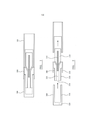
[0068] A Figura 2 mostra o sistema da Figura 1 em um estado desmontado;[0068] Figure 2 shows the system of Figure 1 in a disassembled state;
[0069] A Figura 3 é uma vista em perspectiva de um sistema do tipo ilustrado na Figura 1 com a tampa do bocal removida; e[0069] Figure 3 is a perspective view of a system of the type illustrated in Figure 1 with the nozzle cap removed; and
[0070] A Figura 4 é uma vista em perspectiva do sistema da Figura 3 com a tampa de bocal inserida.[0070] Figure 4 is a perspective view of the system of Figure 3 with the nozzle cap inserted.
[0071] A Figura 1 é uma secção transversal esquemática de um sistema gerador de aerossol de acordo com uma modalidade da invenção. O sistema compreende um corpo principal 100, um cartucho 200 e tampa de bocal 300.[0071] Figure 1 is a schematic cross-section of an aerosol generating system according to an embodiment of the invention. The system comprises a
[0072] A Figura 2 mostra o sistema da Figura 1 em um estado desmontado com os três componentes do corpo principal 100, do cartucho 200 e da tampa do bocal 300 mostrados separadamente um do outro.[0072] Figure 2 shows the system of Figure 1 in a disassembled state with the three components of the
[0073] O sistema mostrado nas Figuras 1 e 2 é do tipo descrito em WO2009/132793.[0073] The system shown in Figures 1 and 2 is of the type described in WO2009/132793.
[0074] O corpo principal 100 do sistema tem um fornecimento de energia elétrica, na forma de uma bateria e um circuito elétrico em forma de hardware. O cartucho 200 tem um substrato de formação de aerossol dentro de uma parte de armazenamento de líquido 210 e um aquecedor (não mostrado) que, quando em uso, vaporiza o substrato de formação de aerossol para formar um aerossol. Um pavio capilar 215 se estende desde dentro da parte de armazenamento de líquido 210 até uma posição dentro de uma câmara de formação de aerossol 225. O aquecedor está sob a forma de um elemento de aquecimento resistivo, como um aquecedor de bobina, em contato com o pavio capilar. A energia para o aquecedor elétrico é fornecida pela bateria dentro do corpo principal 100. O contato elétrico é feito entre o cartucho 200 e o corpo principal 100 quando eles estão em uma condição montada, conforme mostrado na Figura 1.[0074] The
[0075] Uma entrada de ar ou entradas (não mostradas), que podem ser formadas tanto no corpo principal 100 quanto no cartucho 200, ou entre o corpo principal e o cartucho, permitem que o ar entre no dispositivo e passe através da câmara de formação de aerossol 225 até uma saída 220. Em uso, o ar é tragado através da entrada de ar até a saída de ar pela ação de um usuário tragando ou inalando pela tampa do bocal 300. O ar ambiente entra pela entrada de ar ou entradas de ar e passa pelo elemento de aquecimento e pelo pavio capilar onde ele arrasta o substrato de formação de aerossol vaporizado. Então, substrato de formação de aerossol vaporizado esfria para formar um aerossol antes de sair pela saída 220.[0075] An air inlet or inlets (not shown), which can be formed in either the
[0076] Um sistema de detecção de sopro (não mostrado), fornecido no corpo principal ou no cartucho, percebe que o usuário tragou pela tampa do bocal. Em seguida, a bateria fornece energia para o elemento de aquecimento aquecer a extremidade do pavio cercada pelo elemento de aquecimento. O substrato líquido de formação de aerossol nessa extremidade do pavio é vaporizado pelo elemento de aquecimento para criar um vapor supersaturado. Ao mesmo tempo, o líquido que está sendo vaporizado é substituído por líquido adicional que é puxado pelo pavio através de ação capilar. O vapor supersaturado que foi criado é misturado com e transportado pelo fluxo de ar. Conforme descrito anteriormente, o vapor se condensa na câmara de formação de aerossol para formar um aerossol inalável, que é transportador através da saída 220 e para dentro da boca do usuário.[0076] A breath detection system (not shown), provided in the main body or cartridge, senses that the user has swallowed through the mouthpiece cap. The battery then supplies energy to the heating element to heat the end of the wick surrounded by the heating element. The liquid aerosol forming substrate at that end of the wick is vaporized by the heating element to create a supersaturated vapor. At the same time, the liquid being vaporized is replaced by additional liquid that is pulled by the wick through capillary action. The supersaturated vapor that has been created is mixed with and transported by the air flow. As described above, vapor condenses in the aerosol formation chamber to form an inhalable aerosol, which is transported through
[0077] Nesta modalidade, a tampa do bocal 300 se acopla ao cartucho 200. A tampa do bocal 300 é formada de acetato de celulose, coberta com uma camada externa de papel. A tampa do bocal é composta por uma parte tubular 310 e uma porção do filtro 320. A porção tubular da tampa do bocal desliza sobre uma primeira parede 230 do cartucho, mas dentro de uma segunda parede 235 do cartucho. A primeira e a segunda parede do cartucho definem um recesso anular 240, no qual uma parte da porção tubular da tampa do bocal é retida, como mostrado na Figura 1.[0077] In this modality, the
[0078] Nesta modalidade, a tampa do bocal, o cartucho e o corpo principal são todos de secção circular, como pode ser visto mais claramente nas Figuras 3 e 4. A Figura 3 mostra um dispositivo do tipo mostrado na Figura 1 e na Figura 2 com a tampa do bocal 300 separada do corpo principal 100 e do cartucho 200. A Figura 4 mostra o sistema com a tampa do bocal 300 acoplada pela reentrância 240 no cartucho 200. O sistema na configuração da Figura 4 está pronto para uso.[0078] In this embodiment, the mouthpiece cap, cartridge and main body are all circular in section, as can be seen more clearly in Figures 3 and 4. Figure 3 shows a device of the type shown in Figure 1 and Figure 2 with the
[0079] Para garantir que a tampa do bocal seja retida no recesso 240 durante o uso, o recesso 240 é dimensionado de foram a comprimir a porção tubular 310 da tampa do bocal 300. A porção tubular da tampa do bocal é formada de um material que é facilmente comprimido, mas é resiliente. A extremidade aberta do recesso 240 pode ser alargada para permitir uma inserção fácil da tampa do bocal 300 dentro do recesso 240. Uma extremidade de inserção da tampa do bocal 300 também pode ser afunilada para garantir uma inserção fácil da tampa do bocal dentro do recesso. A primeira parede 230 também pode ser afunilada para permitir a inserção fácil de uma tampa de bocal, mas aumentando a compressão do filtro do bocal, conforme ele é totalmente inserido no recesso.[0079] To ensure that the nozzle cap is retained in the
[0080] Uma pluralidade de tampas de bocal 300 pode ser fornecida em um único pacote, possivelmente com um cartucho 200. As tampas do bocal podem ser embaladas de forma que, quando o pacote for aberto, as extremidades abertas das porções tubulares 310 fiquem voltadas para o exterior do pacote. Um usuário precisaria então, simplesmente, introduzir o dispositivo (ou seja, o cartucho 200 montado ao corpo principal) em uma tampa de bocal selecionada, desse modo, inserindo a tampa do bocal no recesso sem ter que remover a tampa do bocal do pacote e inserir manualmente. Depois de uma sessão de fumar, a tampa do bocal usada pode ser retirada do recesso e descartada ou limpa.[0080] A plurality of nozzle caps 300 can be provided in a single pack, possibly with a
[0081] A tampa de bocal pode fornecer filtragem muito baixa do aerossol, se desejado. Alternativamente, a porção de filtro 320 pode ser mais espessa ou formada de forma diferente para fornecer filtragem significativa do aerossol, conforme desejado.[0081] The nozzle cap can provide very low aerosol filtration if desired. Alternatively,
[0082] A primeira e a segunda paredes desta modalidade são formadas a partir de polipropileno e são moldadas por injeção. No entanto, podem ser utilizados quaisquer materiais e processos de fabricação apropriados. Para melhorar a retenção da tampa de bocal 300 no recesso 240, elementos adicionais podem ser fornecidos. Por exemplo, pode-se prever uma pluralidade de travas ou farpas moldadas dentro do recesso, cada uma atuando para segurar as tampas de bocal. Alternativamente, uma ou mais estrias ou saliências podem ser fornecidas na primeira ou na segunda parede. As estrias ou saliências podem ser formadas a partir de um material maleável.[0082] The first and second walls of this modality are formed from polypropylene and are injection molded. However, any suitable materials and manufacturing processes can be used. To improve retention of the
[0083] Um mecanismo de aperto pode ser fornecido para permitir a fixação acionada manualmente da tampa do bocal após a inserção no recesso. Por exemplo, um anel de vedação em O resiliente ou uma mola helicoidal pode ser recebido em um sulco na segunda parede, o anel de vedação em O ou a mola sendo configurada para segurar uma tampa de bocal recebida no recesso. Pode ser fornecido um colar deslizável em torno do anel de vedação em O ou da mola, em que o colar deslizável é móvel entre uma primeira posição, na qual o colar não comprime o anel de vedação em O resiliente ou a mola, e uma segunda posição, na qual o colar comprime o anel de vedação em O resiliente ou a mola.[0083] A clamping mechanism may be provided to allow manually actuated clamping of the nozzle cap after insertion into the recess. For example, a resilient O-ring or coil spring may be received in a groove in the second wall, the O-ring or spring being configured to hold a nozzle cap received in the recess. A slip collar around the O-ring or spring may be provided, wherein the slip collar is movable between a first position in which the collar does not compress the resilient O‑ring or spring, and a second position in which the collar compresses the resilient O-ring or spring.
[0084] A tampa do bocal e o dispositivo gerador de aerossol, de acordo com a invenção, têm várias vantagens, especialmente para um sistema para fumar operado eletricamente. Um novo bocal pode ser utilizado para cada sessão de fumar. Isso melhora a higiene e permite que um sistema de fumar seja compartilhado entre os usuários mais prontamente. A tampa do bocal pode ser feita com as mesmas dimensões, aparência e sensação de um cigarro convencional, que é preferido por muitos usuários. As tampas do bocal podem ser fabricadas utilizando os mesmos materiais, processos e tecnologia que os filtros de cigarro convencional, que já são produzidos, baratos e em grandes volumes. O uso dos mesmos materiais que os filtros convencionais também tem a vantagem que estes filtros foram exaustivamente testados para o mercado de cigarros convencionais e são conhecidos por serem adequados para uso como uma tampa de bocal.[0084] The mouthpiece cover and the aerosol generating device according to the invention have several advantages, especially for an electrically operated smoking system. A new mouthpiece can be used for each smoking session. This improves hygiene and allows a smoking system to be shared among users more readily. The mouthpiece cap can be made with the same dimensions, look and feel as a conventional cigarette, which is preferred by many users. Nozzle caps can be manufactured using the same materials, processes and technology as conventional cigarette filters, which are already produced, inexpensive and in large volumes. Using the same materials as conventional filters also has the advantage that these filters have been extensively tested for the conventional cigarette market and are known to be suitable for use as a mouthpiece cap.
[0085] Deve ficar claro que muitas variações são possíveis para a modalidade descrita com referência ás Figuras de 1 a 4. Por exemplo, os comprimentos relativos da primeira e da segunda parede podem ser diferentes, e o comprimento da tampa do bocal pode ser alterado para atender a preferência do usuário ou estética.[0085] It should be clear that many variations are possible for the modality described with reference to Figures 1 to 4. For example, the relative lengths of the first and second wall may be different, and the length of the nozzle cap may be changed to suit user preference or aesthetics.
[0086] Além disso, a tampa do bocal e sua retenção em um recesso anular podem ser utilizadas com diferentes construções em sistema gerador de aerossol. Por exemplo, um dispositivo gerador de aerossol pode ser configurado para que o cartucho seja mantido inteiramente dentro de uma carcaça principal. Nesse caso, a segunda parede, e possivelmente também a primeira parede, seria parte da carcaça principal. Alternativamente, o cartucho pode incluir a primeira parede e a carcaça principal compreende a segunda parede. O cartucho pode até mesmo incluir somente uma parte da primeira ou da segunda parede ou uma parte de ambas primeira e segunda paredes.[0086] In addition, the nozzle cap and its retention in an annular recess can be used with different constructions in aerosol generating system. For example, an aerosol generating device can be configured so that the cartridge is kept entirely within a main housing. In that case, the second wall, and possibly also the first wall, would be part of the main housing. Alternatively, the cartridge may include the first wall and the main housing comprises the second wall. The cartridge can even include only a part of the first or second wall or a part of both the first and second walls.
[0087] O dispositivo gerador de aerossol pode não incluir um cartucho separado e a carcaça principal. Em vez disto, a carcaça principal pode conter o substrato de formação de aerossol. Neste caso, o dispositivo pode ser recarregável com o substrato ou pode ser descartado quando o substrato for consumido.[0087] The aerosol generating device may not include a separate cartridge and the main housing. Instead, the main housing may contain the aerosol forming substrate. In this case, the device can be rechargeable with the substrate or can be discarded when the substrate is consumed.
[0088] Os exemplos das modalidades descritas anteriormente ilustram, mas não limitam. Considerando os exemplos de formas de realização abordados acima, outras formas de realização consistentes com os exemplos de formas de realização mencionados anteriormente ficarão agora evidentes para um especialista normal da área.[0088] The examples of the modalities described above illustrate, but do not limit. Considering the examples of embodiments discussed above, other embodiments consistent with the examples of embodiments mentioned above will now be apparent to a person of ordinary skill in the art.
Claims (7)
Applications Claiming Priority (3)
| Application Number | Priority Date | Filing Date | Title |
|---|---|---|---|
| EP13159544.9 | 2013-03-15 | ||
| EP13159544 | 2013-03-15 | ||
| PCT/EP2013/077645 WO2014139609A2 (en) | 2013-03-15 | 2013-12-20 | An aerosol-generating system with a replacable mouthpiece cover |
Publications (3)
| Publication Number | Publication Date |
|---|---|
| BR112015020606A2 BR112015020606A2 (en) | 2017-07-18 |
| BR112015020606A8 BR112015020606A8 (en) | 2019-11-12 |
| BR112015020606B1 true BR112015020606B1 (en) | 2021-06-22 |
Family
ID=47900870
Family Applications (1)
| Application Number | Title | Priority Date | Filing Date |
|---|---|---|---|
| BR112015020606-9A BR112015020606B1 (en) | 2013-03-15 | 2013-12-20 | KIT FOR AN AEROSOL GENERATING SYSTEM |
Country Status (21)
| Country | Link |
|---|---|
| US (1) | US10206428B2 (en) |
| EP (1) | EP2967136B1 (en) |
| JP (2) | JP6649089B2 (en) |
| KR (1) | KR102240569B1 (en) |
| CN (1) | CN105050436B (en) |
| AR (1) | AR094334A1 (en) |
| AU (1) | AU2013382371B2 (en) |
| BR (1) | BR112015020606B1 (en) |
| CA (1) | CA2903178A1 (en) |
| HK (1) | HK1214926A1 (en) |
| IL (1) | IL240250B (en) |
| MX (1) | MX368237B (en) |
| MY (1) | MY175998A (en) |
| NZ (1) | NZ712327A (en) |
| PH (1) | PH12015501693A1 (en) |
| RU (1) | RU2661840C2 (en) |
| SG (1) | SG11201507442TA (en) |
| TW (1) | TWI623275B (en) |
| UA (1) | UA114953C2 (en) |
| WO (1) | WO2014139609A2 (en) |
| ZA (1) | ZA201505548B (en) |
Families Citing this family (103)
| Publication number | Priority date | Publication date | Assignee | Title |
|---|---|---|---|---|
| US10244793B2 (en) | 2005-07-19 | 2019-04-02 | Juul Labs, Inc. | Devices for vaporization of a substance |
| US10517530B2 (en) | 2012-08-28 | 2019-12-31 | Juul Labs, Inc. | Methods and devices for delivering and monitoring of tobacco, nicotine, or other substances |
| US10279934B2 (en) | 2013-03-15 | 2019-05-07 | Juul Labs, Inc. | Fillable vaporizer cartridge and method of filling |
| KR20230013165A (en) | 2013-05-06 | 2023-01-26 | 쥴 랩스, 인크. | Nicotine salt formulations for aerosol devices and methods thereof |
| CN111642812A (en) | 2013-06-14 | 2020-09-11 | 尤尔实验室有限公司 | Multiple heating elements with individual vaporizable materials in electronic vaporization devices |
| US10039321B2 (en) | 2013-11-12 | 2018-08-07 | Vmr Products Llc | Vaporizer |
| US10980273B2 (en) | 2013-11-12 | 2021-04-20 | VMR Products, LLC | Vaporizer, charger and methods of use |
| AU2014357622B2 (en) | 2013-12-05 | 2019-10-24 | Juul Labs, Inc. | Nicotine liquid formulations for aerosol devices and methods thereof |
| US10058129B2 (en) | 2013-12-23 | 2018-08-28 | Juul Labs, Inc. | Vaporization device systems and methods |
| US20160366947A1 (en) | 2013-12-23 | 2016-12-22 | James Monsees | Vaporizer apparatus |
| USD842536S1 (en) | 2016-07-28 | 2019-03-05 | Juul Labs, Inc. | Vaporizer cartridge |
| US10159282B2 (en) | 2013-12-23 | 2018-12-25 | Juul Labs, Inc. | Cartridge for use with a vaporizer device |
| KR102256889B1 (en) | 2013-12-23 | 2021-05-31 | 쥴 랩스, 인크. | Vaporization device systems and methods |
| USD825102S1 (en) | 2016-07-28 | 2018-08-07 | Juul Labs, Inc. | Vaporizer device with cartridge |
| US10076139B2 (en) | 2013-12-23 | 2018-09-18 | Juul Labs, Inc. | Vaporizer apparatus |
| US9549573B2 (en) * | 2013-12-23 | 2017-01-24 | Pax Labs, Inc. | Vaporization device systems and methods |
| US10709173B2 (en) | 2014-02-06 | 2020-07-14 | Juul Labs, Inc. | Vaporizer apparatus |
| TWI761216B (en) | 2014-02-06 | 2022-04-11 | 美商尤爾實驗室有限公司 | A device for generating an inhalable aerosol and a separable cartridge for use therewith |
| US11478021B2 (en) | 2014-05-16 | 2022-10-25 | Juul Labs, Inc. | Systems and methods for aerosolizing a vaporizable material |
| US10226076B2 (en) | 2014-11-17 | 2019-03-12 | Mcneil Ab | Disposable cartridge for use in an electronic nicotine delivery system |
| ES2738730T3 (en) | 2014-11-17 | 2020-01-24 | Mcneil Ab | Electronic nicotine administration system |
| KR102627987B1 (en) | 2014-12-05 | 2024-01-22 | 쥴 랩스, 인크. | Calibrated dose control |
| CN107072321B (en) | 2014-12-15 | 2021-05-14 | 菲利普莫里斯生产公司 | Electronic liquid collapsible tube |
| US10064432B2 (en) | 2015-04-22 | 2018-09-04 | Altria Client Services Llc | Pod assembly, dispensing body, and E-vapor apparatus including the same |
| USD980507S1 (en) | 2015-04-22 | 2023-03-07 | Altria Client Services Llc | Electronic vaping device |
| UA122407C2 (en) | 2015-04-22 | 2020-11-10 | Олтріа Клайєнт Сервісиз Ллк | Pod assembly, dispensing body, and e-vapor apparatus including the same |
| US10104913B2 (en) | 2015-04-22 | 2018-10-23 | Altria Client Services Llc | Pod assembly, dispensing body, and E-vapor apparatus including the same |
| GB201511359D0 (en) | 2015-06-29 | 2015-08-12 | Nicoventures Holdings Ltd | Electronic vapour provision system |
| GB201511358D0 (en) | 2015-06-29 | 2015-08-12 | Nicoventures Holdings Ltd | Electronic aerosol provision systems |
| GB201511349D0 (en) | 2015-06-29 | 2015-08-12 | Nicoventures Holdings Ltd | Electronic aerosol provision systems |
| EP3788892B1 (en) * | 2015-07-14 | 2024-03-27 | Dynavap, LLC | Exothermal vaporizer |
| EP3155909B1 (en) * | 2015-10-16 | 2018-03-21 | Fontem Holdings 1 B.V. | Slide-on attachment for electronic smoking devices |
| PL3167728T3 (en) * | 2015-11-12 | 2020-10-05 | Fontem Holdings 1 B.V. | Electronic smoking device with cavity for liquid reservoir |
| GB2544493B (en) | 2015-11-17 | 2020-06-17 | Nerudia Ltd | A dispenser for dispensing a liquid for a substitute smoking device |
| DE202017007467U1 (en) | 2016-02-11 | 2021-12-08 | Juul Labs, Inc. | Fillable vaporizer cartridge |
| EP3419443A4 (en) | 2016-02-11 | 2019-11-20 | Juul Labs, Inc. | Securely attaching cartridges for vaporizer devices |
| US9807851B2 (en) * | 2016-02-19 | 2017-10-31 | Vivint, Inc. | Identity-based environment adjusting techniques |
| WO2017147560A1 (en) | 2016-02-25 | 2017-08-31 | Pax Labs, Inc. | Vaporization device control systems and methods |
| US10405582B2 (en) | 2016-03-10 | 2019-09-10 | Pax Labs, Inc. | Vaporization device with lip sensing |
| WO2017182485A1 (en) * | 2016-04-20 | 2017-10-26 | Philip Morris Products S.A. | Hybrid aerosol-generating element and method for manufacturing a hybrid aerosol-generating element |
| CN113243567A (en) * | 2016-05-31 | 2021-08-13 | 菲利普莫里斯生产公司 | Electrically heated aerosol-generating system and kit |
| WO2017211600A1 (en) | 2016-06-08 | 2017-12-14 | Philip Morris Products S.A. | Electrically operated aerosol-generating system with multiple-component aerosol-generating article |
| GB201610220D0 (en) * | 2016-06-13 | 2016-07-27 | Nicoventures Holdings Ltd | Aerosol delivery device |
| USD849996S1 (en) | 2016-06-16 | 2019-05-28 | Pax Labs, Inc. | Vaporizer cartridge |
| USD836541S1 (en) | 2016-06-23 | 2018-12-25 | Pax Labs, Inc. | Charging device |
| USD851830S1 (en) | 2016-06-23 | 2019-06-18 | Pax Labs, Inc. | Combined vaporizer tamp and pick tool |
| USD848057S1 (en) | 2016-06-23 | 2019-05-07 | Pax Labs, Inc. | Lid for a vaporizer |
| US10231485B2 (en) * | 2016-07-08 | 2019-03-19 | Rai Strategic Holdings, Inc. | Radio frequency to direct current converter for an aerosol delivery device |
| US11660403B2 (en) | 2016-09-22 | 2023-05-30 | Juul Labs, Inc. | Leak-resistant vaporizer device |
| CN106343615B (en) * | 2016-11-09 | 2023-06-09 | 云南中烟工业有限责任公司 | Photon heating low-temperature smoking set |
| US10206431B2 (en) | 2016-11-18 | 2019-02-19 | Rai Strategic Holdings, Inc. | Charger for an aerosol delivery device |
| CA3037645A1 (en) * | 2016-11-29 | 2018-06-07 | Philip Morris Products S.A. | Vaporizer for an aerosol-generating system and vaporizing method |
| JP7121746B2 (en) | 2016-12-19 | 2022-08-18 | フィリップ・モーリス・プロダクツ・ソシエテ・アノニム | Aerosol generating system with external cartridge |
| US10863769B2 (en) * | 2017-03-28 | 2020-12-15 | National Concessions Group Inc. | Mouthpiece for smoking and vaporizing devices |
| KR102216139B1 (en) | 2017-04-28 | 2021-02-16 | 주식회사 케이티앤지 | Method and apparatus for generating aerosols |
| WO2018199504A1 (en) * | 2017-04-28 | 2018-11-01 | 주식회사 케이티앤지 | Aerosol generation method and apparatus |
| CN109419034A (en) * | 2017-08-21 | 2019-03-05 | 深圳麦克韦尔股份有限公司 | Electronic cigarette and its atomising device and pipe bowl |
| USD887632S1 (en) | 2017-09-14 | 2020-06-16 | Pax Labs, Inc. | Vaporizer cartridge |
| US10512286B2 (en) * | 2017-10-19 | 2019-12-24 | Rai Strategic Holdings, Inc. | Colorimetric aerosol and gas detection for aerosol delivery device |
| US20210000186A1 (en) * | 2018-03-13 | 2021-01-07 | Philip Morris Product S.A. | Cleaning tool for heating element |
| CN112312785A (en) | 2018-06-07 | 2021-02-02 | 尤尔实验室有限公司 | Cartridge for an evaporator device |
| EP3829360B1 (en) * | 2018-08-02 | 2023-11-01 | Philip Morris Products S.A. | System comprising aerosol-generating device and adapter element |
| FR3087093A1 (en) | 2018-10-15 | 2020-04-17 | Juul Labs, Inc. | HEATING ELEMENT |
| EP3876760A1 (en) | 2018-11-08 | 2021-09-15 | Juul Labs, Inc. | Cartridges for vaporizer devices |
| JP2020146313A (en) * | 2019-03-14 | 2020-09-17 | 株式会社三洋物産 | Game machine |
| JP2020146310A (en) * | 2019-03-14 | 2020-09-17 | 株式会社三洋物産 | Game machine |
| JP2020146312A (en) * | 2019-03-14 | 2020-09-17 | 株式会社三洋物産 | Game machine |
| JP2020146297A (en) * | 2019-03-14 | 2020-09-17 | 株式会社三洋物産 | Game machine |
| JP2020146317A (en) * | 2019-03-14 | 2020-09-17 | 株式会社三洋物産 | Game machine |
| JP2020146316A (en) * | 2019-03-14 | 2020-09-17 | 株式会社三洋物産 | Game machine |
| JP2020146311A (en) * | 2019-03-14 | 2020-09-17 | 株式会社三洋物産 | Game machine |
| JP2020146301A (en) * | 2019-03-14 | 2020-09-17 | 株式会社三洋物産 | Game machine |
| JP2020146314A (en) * | 2019-03-14 | 2020-09-17 | 株式会社三洋物産 | Game machine |
| JP2020146307A (en) * | 2019-03-14 | 2020-09-17 | 株式会社三洋物産 | Game machine |
| JP2020146305A (en) * | 2019-03-14 | 2020-09-17 | 株式会社三洋物産 | Game machine |
| JP2020146306A (en) * | 2019-03-14 | 2020-09-17 | 株式会社三洋物産 | Game machine |
| JP2020146303A (en) * | 2019-03-14 | 2020-09-17 | 株式会社三洋物産 | Game machine |
| JP2020146309A (en) * | 2019-03-14 | 2020-09-17 | 株式会社三洋物産 | Game machine |
| JP2020146308A (en) * | 2019-03-14 | 2020-09-17 | 株式会社三洋物産 | Game machine |
| JP2020146300A (en) * | 2019-03-14 | 2020-09-17 | 株式会社三洋物産 | Game machine |
| JP2020146304A (en) * | 2019-03-14 | 2020-09-17 | 株式会社三洋物産 | Game machine |
| JP2020146318A (en) * | 2019-03-14 | 2020-09-17 | 株式会社三洋物産 | Game machine |
| JP2020146299A (en) * | 2019-03-14 | 2020-09-17 | 株式会社三洋物産 | Game machine |
| JP2020146302A (en) * | 2019-03-14 | 2020-09-17 | 株式会社三洋物産 | Game machine |
| JP2020146315A (en) * | 2019-03-14 | 2020-09-17 | 株式会社三洋物産 | Game machine |
| GB201904846D0 (en) * | 2019-04-05 | 2019-05-22 | Nicoventures Trading Ltd | Aerosol provision system |
| US11647790B2 (en) * | 2019-04-17 | 2023-05-16 | Sv3, Llc | Vaporizer pod systems |
| CA3137374A1 (en) * | 2019-05-03 | 2020-11-12 | Jt International S.A. | Aerosol generation device with closure |
| EP3962300A1 (en) * | 2019-05-03 | 2022-03-09 | JT International SA | Aerosol generation device with closure |
| US11771850B2 (en) * | 2019-06-18 | 2023-10-03 | Sv3, Llc | Vaporizer pod filtration systems |
| US20200397042A1 (en) * | 2019-06-18 | 2020-12-24 | Michael Barenboym | Carrying case with an elastic implement for smoking tobacco or cannabis |
| CN110179168A (en) * | 2019-06-24 | 2019-08-30 | 陈玉水 | A kind of electronic cigarette with folding protective device |
| US11528937B2 (en) | 2019-11-26 | 2022-12-20 | Altria Client Services Llc | Nicotine pod assemblies and nicotine e-vaping devices |
| US11528938B2 (en) | 2019-11-26 | 2022-12-20 | Altria Client Services Llc | Non-nicotine pod assemblies and non-nicotine e-vaping devices |
| US11596172B2 (en) | 2019-11-26 | 2023-03-07 | Altria Client Services Llc | Non-nicotine pod assemblies and non-nicotine e-vaping devices |
| US11484062B2 (en) | 2019-11-26 | 2022-11-01 | Altria Client Services Llc | Nicotine pod assemblies and nicotine e-vaping devices |
| US11564416B2 (en) | 2019-11-26 | 2023-01-31 | Altria Client Services Llc | Non-nicotine pod assemblies and non-nicotine e-vaping devices |
| US11528939B2 (en) | 2019-11-26 | 2022-12-20 | Altria Client Services Llc | Non-nicotine pod assemblies and non-nicotine e-vaping devices |
| US11490656B2 (en) | 2019-11-26 | 2022-11-08 | Altria Client Services Llc | Nicotine pod assemblies and nicotine e-vaping devices |
| US11576432B2 (en) | 2019-11-26 | 2023-02-14 | Altria Client Services Llc | Nicotine pod assemblies and nicotine e-vaping devices |
| CN110973720A (en) * | 2019-12-13 | 2020-04-10 | 深圳麦克韦尔科技有限公司 | Electronic atomization device, atomizer thereof and manufacturing method of vent pipe |
| US11930862B2 (en) * | 2020-05-15 | 2024-03-19 | Simrell Collection, Llc | Mouthpiece with adjustment |
| WO2023174654A1 (en) * | 2022-03-14 | 2023-09-21 | Jt International Sa | A cartridge for a vapour generating device and a vapour generating device |
Family Cites Families (48)
| Publication number | Priority date | Publication date | Assignee | Title |
|---|---|---|---|---|
| US2624345A (en) * | 1948-11-13 | 1953-01-06 | Jacob R Rosenthal | Smoking pipe |
| US3200819A (en) * | 1963-04-17 | 1965-08-17 | Herbert A Gilbert | Smokeless non-tobacco cigarette |
| DE2442774C3 (en) * | 1974-09-06 | 1979-01-04 | Klaus Paul 8070 Ingolstadt Uhle | Smoking device for sucking in gas-containing mixtures |
| US4039213A (en) * | 1976-03-08 | 1977-08-02 | Tom Walters | Couplings |
| US4429703A (en) * | 1982-02-22 | 1984-02-07 | William Haber | Cigarette substitute |
| US4922901A (en) * | 1988-09-08 | 1990-05-08 | R. J. Reynolds Tobacco Company | Drug delivery articles utilizing electrical energy |
| US5269327A (en) * | 1989-12-01 | 1993-12-14 | Philip Morris Incorporated | Electrical smoking article |
| US5060671A (en) * | 1989-12-01 | 1991-10-29 | Philip Morris Incorporated | Flavor generating article |
| CN2125763U (en) * | 1992-04-13 | 1992-12-23 | 李岗 | V-shaped pipe joint |
| US5290046A (en) * | 1992-07-08 | 1994-03-01 | Houston James L | Internal live loading packing gland |
| KR100289448B1 (en) | 1997-07-23 | 2001-05-02 | 미즈노 마사루 | Flavor generator |
| US6164287A (en) * | 1998-06-10 | 2000-12-26 | R. J. Reynolds Tobacco Company | Smoking method |
| DE19854005C2 (en) | 1998-11-12 | 2001-05-17 | Reemtsma H F & Ph | Inhalable aerosol delivery system |
| SE9804525D0 (en) * | 1998-12-23 | 1998-12-23 | Itt Mfg Enterprises Inc | Locking |
| US6418937B1 (en) * | 1999-04-23 | 2002-07-16 | Cristom Import & Export, Inc. | Tobacco pipe assembly with filter adapter |
| US6662978B2 (en) * | 2002-05-13 | 2003-12-16 | Shin-Shuoh Lin | Stopper with interchangeable plug |
| DE102005016415A1 (en) * | 2005-04-08 | 2006-11-02 | Nicstic Ag | Filter connection for smokeless cigarette, has heating peg interlocked to filter mouthpiece and fitted into nicotine deposit and acetate-made filter |
| US20070215167A1 (en) * | 2006-03-16 | 2007-09-20 | Evon Llewellyn Crooks | Smoking article |
| CN201067079Y (en) * | 2006-05-16 | 2008-06-04 | 韩力 | Simulation aerosol inhaler |
| JP2008035742A (en) * | 2006-08-03 | 2008-02-21 | British American Tobacco Pacific Corporation | Evaporating apparatus |
| DE102006041042B4 (en) * | 2006-09-01 | 2009-06-25 | W + S Wagner + Söhne Mess- und Informationstechnik GmbH & Co.KG | Device for dispensing a nicotine-containing aerosol |
| US7726320B2 (en) * | 2006-10-18 | 2010-06-01 | R. J. Reynolds Tobacco Company | Tobacco-containing smoking article |
| CN201207922Y (en) | 2007-09-29 | 2009-03-18 | 伯纳德·马斯 | Simulation cigarette holder for replacing cigarette |
| EP2113178A1 (en) * | 2008-04-30 | 2009-11-04 | Philip Morris Products S.A. | An electrically heated smoking system having a liquid storage portion |
| GB0813686D0 (en) * | 2008-07-25 | 2008-09-03 | Gamucci Ltd | A method and apparatus relating to electronic smoking-substitute devices |
| GB0823491D0 (en) * | 2008-12-23 | 2009-01-28 | Kind Consumer Ltd | A simulated cigarette device |
| JP5510968B2 (en) | 2009-02-23 | 2014-06-04 | 日本たばこ産業株式会社 | Non-heated tobacco flavor inhaler |
| GB2473264A (en) * | 2009-09-08 | 2011-03-09 | British American Tobacco Co | Volatilization Device |
| WO2012117578A1 (en) * | 2011-03-02 | 2012-09-07 | Shimizu Kazuhiko | Mouthpiece |
| US9861772B2 (en) * | 2010-05-15 | 2018-01-09 | Rai Strategic Holdings, Inc. | Personal vaporizing inhaler cartridge |
| US8499766B1 (en) * | 2010-09-15 | 2013-08-06 | Kyle D. Newton | Electronic cigarette with function illuminator |
| CN201839801U (en) * | 2010-11-17 | 2011-05-25 | 刘秋明 | Electronic cigarette and cigarette cartridge thereof |
| US8978663B2 (en) * | 2010-12-06 | 2015-03-17 | Kyle D. Newton | Charger package for electronic cigarette components |
| EP2468117A1 (en) * | 2010-12-24 | 2012-06-27 | Philip Morris Products S.A. | An aerosol generating system having means for determining depletion of a liquid substrate |
| CN102106611B (en) | 2011-03-28 | 2013-01-16 | 深圳市康泰尔电子有限公司 | Electronic cigarette |
| US8528569B1 (en) * | 2011-06-28 | 2013-09-10 | Kyle D. Newton | Electronic cigarette with liquid reservoir |
| US9078473B2 (en) * | 2011-08-09 | 2015-07-14 | R.J. Reynolds Tobacco Company | Smoking articles and use thereof for yielding inhalation materials |
| US9498588B2 (en) * | 2011-12-14 | 2016-11-22 | Atmos Nation, LLC | Portable pen sized electric herb vaporizer with ceramic heating chamber |
| KR101184758B1 (en) | 2012-01-13 | 2012-09-19 | 이영인 | Cartridge of electric cigarette for preventing leakage |
| US9282772B2 (en) * | 2012-01-31 | 2016-03-15 | Altria Client Services Llc | Electronic vaping device |
| CN202664230U (en) * | 2012-05-31 | 2013-01-16 | 陈志平 | Electronic atomizing inhalation device and plug-in type connecting structure thereof |
| US9308336B2 (en) * | 2012-09-19 | 2016-04-12 | Kyle D. Newton | Refill diverter for electronic cigarette |
| US8794245B1 (en) * | 2013-01-17 | 2014-08-05 | Njoy, Inc. | Aroma pack for an electronic cigarette |
| US8910640B2 (en) * | 2013-01-30 | 2014-12-16 | R.J. Reynolds Tobacco Company | Wick suitable for use in an electronic smoking article |
| US9609893B2 (en) * | 2013-03-15 | 2017-04-04 | Rai Strategic Holdings, Inc. | Cartridge and control body of an aerosol delivery device including anti-rotation mechanism and related method |
| EP2779786A1 (en) * | 2013-03-15 | 2014-09-17 | Philip Morris Products S.A. | A method of manufacture for a heater assembly for use with a liquid filled cartridge |
| US9642397B2 (en) * | 2014-03-31 | 2017-05-09 | Westfield Limited (Ltd.) | Personal vaporizer with liquid supply by suction |
| US9010335B1 (en) * | 2014-05-13 | 2015-04-21 | Njoy, Inc. | Mechanisms for vaporizing devices |
-
2013
- 2013-12-20 MX MX2015013049A patent/MX368237B/en active IP Right Grant
- 2013-12-20 NZ NZ712327A patent/NZ712327A/en not_active IP Right Cessation
- 2013-12-20 MY MYPI2015702706A patent/MY175998A/en unknown
- 2013-12-20 UA UAA201508875A patent/UA114953C2/en unknown
- 2013-12-20 AU AU2013382371A patent/AU2013382371B2/en active Active
- 2013-12-20 WO PCT/EP2013/077645 patent/WO2014139609A2/en active Application Filing
- 2013-12-20 EP EP13821816.9A patent/EP2967136B1/en active Active
- 2013-12-20 BR BR112015020606-9A patent/BR112015020606B1/en active IP Right Grant
- 2013-12-20 US US14/776,167 patent/US10206428B2/en active Active
- 2013-12-20 JP JP2015561964A patent/JP6649089B2/en active Active
- 2013-12-20 CN CN201380074693.2A patent/CN105050436B/en active Active
- 2013-12-20 SG SG11201507442TA patent/SG11201507442TA/en unknown
- 2013-12-20 RU RU2015142843A patent/RU2661840C2/en active
- 2013-12-20 KR KR1020157024636A patent/KR102240569B1/en active IP Right Grant
- 2013-12-20 CA CA2903178A patent/CA2903178A1/en not_active Abandoned
- 2013-12-26 TW TW102148341A patent/TWI623275B/en active
- 2013-12-27 AR ARP130105091A patent/AR094334A1/en active IP Right Grant
-
2015
- 2015-07-30 IL IL240250A patent/IL240250B/en active IP Right Grant
- 2015-07-31 PH PH12015501693A patent/PH12015501693A1/en unknown
- 2015-07-31 ZA ZA2015/05548A patent/ZA201505548B/en unknown
-
2016
- 2016-03-11 HK HK16102856.1A patent/HK1214926A1/en unknown
-
2018
- 2018-10-17 JP JP2018196004A patent/JP2019047792A/en active Pending
Also Published As
Similar Documents
| Publication | Publication Date | Title |
|---|---|---|
| BR112015020606B1 (en) | KIT FOR AN AEROSOL GENERATING SYSTEM | |
| US11638793B2 (en) | Aerosol generating device having an internal heater | |
| US20220167466A1 (en) | Cartridge with a heater assembly for an aerosol-generating system | |
| KR102642833B1 (en) | An aerosol-generating system having a heater assembly and a cartridge for an aerosol-generating system having a fluid permeable heater assembly | |
| JP5889941B2 (en) | Electric heating smoking system with liquid storage part | |
| EP2645890B1 (en) | An aerosol generating system with leakage prevention | |
| KR20180134914A (en) | Aerosol generating device with fixing means | |
| BR112014013477B1 (en) | aerosol generation system and method for varying airflow velocity | |
| RU2805500C2 (en) | Aerosol generating device, cartridge and aerosol generating system | |
| BR112016019985B1 (en) | ELECTRICALLY HEATED AEROSOL GENERATOR SYSTEM | |
| NZ624111B2 (en) | An aerosol generating device having an internal heater |
Legal Events
| Date | Code | Title | Description |
|---|---|---|---|
| B06F | Objections, documents and/or translations needed after an examination request according [chapter 6.6 patent gazette] | ||
| B06U | Preliminary requirement: requests with searches performed by other patent offices: procedure suspended [chapter 6.21 patent gazette] | ||
| B07A | Application suspended after technical examination (opinion) [chapter 7.1 patent gazette] | ||
| B09A | Decision: intention to grant [chapter 9.1 patent gazette] | ||
| B16A | Patent or certificate of addition of invention granted [chapter 16.1 patent gazette] |
Free format text: PRAZO DE VALIDADE: 20 (VINTE) ANOS CONTADOS A PARTIR DE 20/12/2013, OBSERVADAS AS CONDICOES LEGAIS. |