BR112015020552B1 - STRUCTURE FOR FRONT PART OF VEHICLE WITH SADDLE - Google Patents
STRUCTURE FOR FRONT PART OF VEHICLE WITH SADDLE Download PDFInfo
- Publication number
- BR112015020552B1 BR112015020552B1 BR112015020552-6A BR112015020552A BR112015020552B1 BR 112015020552 B1 BR112015020552 B1 BR 112015020552B1 BR 112015020552 A BR112015020552 A BR 112015020552A BR 112015020552 B1 BR112015020552 B1 BR 112015020552B1
- Authority
- BR
- Brazil
- Prior art keywords
- vehicle
- front cover
- cover support
- cylindrical section
- tube
- Prior art date
Links
Images

Classifications
-
- B—PERFORMING OPERATIONS; TRANSPORTING
- B62—LAND VEHICLES FOR TRAVELLING OTHERWISE THAN ON RAILS
- B62K—CYCLES; CYCLE FRAMES; CYCLE STEERING DEVICES; RIDER-OPERATED TERMINAL CONTROLS SPECIALLY ADAPTED FOR CYCLES; CYCLE AXLE SUSPENSIONS; CYCLE SIDECARS, FORECARS, OR THE LIKE
- B62K19/00—Cycle frames
- B62K19/30—Frame parts shaped to receive other cycle parts or accessories
- B62K19/38—Frame parts shaped to receive other cycle parts or accessories for attaching brake members
-
- B—PERFORMING OPERATIONS; TRANSPORTING
- B62—LAND VEHICLES FOR TRAVELLING OTHERWISE THAN ON RAILS
- B62J—CYCLE SADDLES OR SEATS; AUXILIARY DEVICES OR ACCESSORIES SPECIALLY ADAPTED TO CYCLES AND NOT OTHERWISE PROVIDED FOR, e.g. ARTICLE CARRIERS OR CYCLE PROTECTORS
- B62J11/00—Supporting arrangements specially adapted for fastening specific devices to cycles, e.g. supports for attaching maps
- B62J11/10—Supporting arrangements specially adapted for fastening specific devices to cycles, e.g. supports for attaching maps for mechanical cables, hoses, pipes or electric wires, e.g. cable guides
- B62J11/13—Supporting arrangements specially adapted for fastening specific devices to cycles, e.g. supports for attaching maps for mechanical cables, hoses, pipes or electric wires, e.g. cable guides specially adapted for mechanical cables
-
- B—PERFORMING OPERATIONS; TRANSPORTING
- B62—LAND VEHICLES FOR TRAVELLING OTHERWISE THAN ON RAILS
- B62J—CYCLE SADDLES OR SEATS; AUXILIARY DEVICES OR ACCESSORIES SPECIALLY ADAPTED TO CYCLES AND NOT OTHERWISE PROVIDED FOR, e.g. ARTICLE CARRIERS OR CYCLE PROTECTORS
- B62J11/00—Supporting arrangements specially adapted for fastening specific devices to cycles, e.g. supports for attaching maps
- B62J11/10—Supporting arrangements specially adapted for fastening specific devices to cycles, e.g. supports for attaching maps for mechanical cables, hoses, pipes or electric wires, e.g. cable guides
- B62J11/19—Supporting arrangements specially adapted for fastening specific devices to cycles, e.g. supports for attaching maps for mechanical cables, hoses, pipes or electric wires, e.g. cable guides specially adapted for electric wires
-
- B—PERFORMING OPERATIONS; TRANSPORTING
- B62—LAND VEHICLES FOR TRAVELLING OTHERWISE THAN ON RAILS
- B62J—CYCLE SADDLES OR SEATS; AUXILIARY DEVICES OR ACCESSORIES SPECIALLY ADAPTED TO CYCLES AND NOT OTHERWISE PROVIDED FOR, e.g. ARTICLE CARRIERS OR CYCLE PROTECTORS
- B62J17/00—Weather guards for riders; Fairings or stream-lining parts not otherwise provided for
- B62J17/02—Weather guards for riders; Fairings or stream-lining parts not otherwise provided for shielding only the rider's front
-
- B—PERFORMING OPERATIONS; TRANSPORTING
- B62—LAND VEHICLES FOR TRAVELLING OTHERWISE THAN ON RAILS
- B62K—CYCLES; CYCLE FRAMES; CYCLE STEERING DEVICES; RIDER-OPERATED TERMINAL CONTROLS SPECIALLY ADAPTED FOR CYCLES; CYCLE AXLE SUSPENSIONS; CYCLE SIDECARS, FORECARS, OR THE LIKE
- B62K2202/00—Motorised scooters
Landscapes
- Engineering & Computer Science (AREA)
- Mechanical Engineering (AREA)
- Motorcycle And Bicycle Frame (AREA)
- Body Structure For Vehicles (AREA)
- Flexible Shafts (AREA)
Abstract
estrutura para parte frontal de veículo com selim. a presente invenção refere-se a uma estrutura para a parte frontal de um veículo com selim que possui: um tubo de cabeça (21) que é fornecido na frente de um chassi de corpo de veículo (20) e que suporta rotativamente uma roda frontal (14) de modo pivotável; um apoio de cobertura frontal (30) que é fornecido ao tubo de cabeça (21) e que se estende na frente do veículo; uma cobertura frontal (41) que é fornecida no apoio de cobertura frontal (30) e que cobre a frente do tubo de cabeça (21); um operador (18) que é fornecido acima do tubo de cabeça (2) e que opera o dispositivo de freio (15) da roda frontal; e um membro de transmissão de força operacional (54) que é disposto dentro da cobertura frontal (41) e que transmite a força operacional do operador (18) ao dispositivo de freio (15). o apoio de cobertura frontal (30) é fornecido com uma seção cilíndrica (34) que é formada em um formato cilíndrico de tal maneira que a parte superior e a parte inferior da mesma são abertas, e o membro de transmissão de força operacional (54) é dirigido de modo a passar através do interior da seção cilíndrica (34).structure for the front part of a vehicle with saddle. The present invention relates to a structure for the front part of a saddle vehicle having: a head tube (21) which is provided at the front of a vehicle body chassis (20) and which rotatably supports a front wheel (14) pivotable; a front cover support (30) which is provided to the head tube (21) and which extends at the front of the vehicle; a front cover (41) which is provided on the front cover support (30) and which covers the front of the head tube (21); an operator (18) which is provided above the head tube (2) and which operates the braking device (15) of the front wheel; and an operating force transmission member (54) which is disposed within the front cover (41) and which transmits the operator's operating force (18) to the braking device (15). The front cover support (30) is provided with a cylindrical section (34) which is formed into a cylindrical shape in such a way that the upper part and the lower part thereof are open, and the operating force transmission member (54 ) is directed so as to pass through the interior of the cylindrical section (34).
Description
[001] A presente invenção refere-se a um aperfeiçoamento em uma estrutura para uma parte frontal de um veículo com selim.[001] The present invention relates to an improvement in a structure for a front part of a vehicle with a saddle.
[002] Como veículos do tipo de montar no selim ou veículos com selim, os assim chamados veículos do tipo desprotegido sem cobertura frontal e veículos tendo uma cobertura frontal são praticamente usados. Quando um veículo tem uma cobertura frontal, o veículo deve ter uma estrutura de suporte para suportar a cobertura frontal. Tais tipos de estruturas de suporte são conhecidos, por exemplo, como descrito na Literatura de Patente 1.[002] As saddle-mounted vehicles or saddle-mounted vehicles, so-called unprotected type vehicles without a front cover and vehicles having a front cover are practically used. When a vehicle has a front cover, the vehicle must have a support structure to support the front cover. Such types of support structures are known, for example, as described in
[003] Um veículo com selim descrito na Literatura de Patente 1 inclui um apoio de fixação fornecido em um apoio de fixação fornecido em um tubo frontal através de uma peça de fixação, e uma cobertura frontal suportada pelo apoio de fixação.[003] A saddled vehicle described in
[004] O veículo com selim ainda inclui uma mangueira de freio ou um cabo de freio colocada dentro da cobertura frontal. Uma vez que a roda frontal é montada de modo orientável no veículo e a mangueira de freio ou o cabo de freio segue a roda frontal e um guidão, é necessário prender uma extensão flexível da mangueira de freio ou do cabo de freio.[004] The saddled vehicle still includes a brake hose or a brake cable placed inside the front cover. Since the front wheel is swivel mounted on the vehicle and the brake hose or brake cable follows the front wheel and a handlebar, it is necessary to attach a flexible extension of the brake hose or brake cable.
[005] No entanto, por causa do apoio de fixação disposto na frente do tubo frontal em um centro em uma direção de largura do veículo, a mangueira de freio ou o cabo de freio não pode ser dirigida na frente do tubo frontal no centro na direção de largura de veículo. Ou seja, a mangueira de freio ou o cabo de freio deve ser dirigida para longe do centro na direção de largura do veículo, e assim o comprimento da mangueira de freio ou do cabo de freio é aumentado. Além disso, é necessário fornecer um membro adicional para limitar a extensão flexível da mangueira de freio ou cabo de freio longo.[005] However, because of the fixing bracket arranged in front of the headtube at a center in a vehicle-wide direction, the brake hose or brake cable cannot be routed in front of the headtube at the center in the vehicle width direction. That is, the brake hose or brake cable must be directed away from the center in the width direction of the vehicle, and thus the length of the brake hose or brake cable is increased. In addition, it is necessary to provide an additional member to limit the flexible extension of the brake hose or long brake cable.
[006] Portanto, no veículo tendo a cobertura frontal, uma estrutura aperfeiçoada para uma parte frontal ou estrutura da parte frontal é desejada, a qual permite que a mangueira de freio ou o cabo de freio seja dirigido na frente do tubo frontal no centro na direção de largura de veículo, enquanto reduz o número de componentes. Literatura da Técnica Anterior Literatura de Patente Literatura de Patente 1: Publicação de Patente Japonesa N° 3457303[006] Therefore, in the vehicle having the front cover, an improved structure for a front end or front end structure is desired, which allows the brake hose or brake cable to be routed in front of the head tube in the center in the vehicle width steering, while reducing the number of components. Prior Art Literature Patent Literature Patent Literature 1: Japanese Patent Publication No. 3457303
[007] É um objetivo da presente invenção fornecer uma estrutura de parte frontal de um veículo com selim que permite que uma mangueira de freio ou um cabo de freio seja dirigido na frente de um tubo frontal em um centro em uma direção de largura de veículo, enquanto reduz o número de componentes.[007] It is an object of the present invention to provide a vehicle front end frame with a saddle that allows a brake hose or brake cable to be routed in front of a head tube at a center in a vehicle-wide direction. , while reducing the number of components.
[008] De acordo com uma forma preferida da presente invenção, é fornecida uma estrutura de parte frontal de um veículo com selim, o qual inclui um tubo frontal disposto para constituir uma parte frontal de uma armação de corpo de veículo e suportando de modo orientável uma roda frontal, um apoio de cobertura frontal fixado ao tubo frontal e se estendendo na direção da frente do veículo, uma cobertura frontal montada no apoio de cobertura frontal para cobrir uma parte frontal do tubo frontal, um operador fornecido acima do tubo frontal para operar um dispositivo de freio da roda frontal, e um membro de transmissão de força operacional na forma de uma mangueira de freio ou um cabo de freio disposto dentro da cobertura frontal para transmitir uma força operacional do operador ao dispositivo de freio, caracterizado pelo fato de que: o apoio de cobertura frontal possui uma seção cilíndrica formada em um formato cilíndrico tendo partes inferiores e superiores da mesma abertas; e a mangueira de freio ou o cabo de freio é disposto para passar através do interior da seção cilíndrica.[008] In accordance with a preferred form of the present invention, there is provided a vehicle front frame with saddle, which includes a front tube arranged to form a front part of a vehicle body frame and orientable supporting a front wheel, a front cover support attached to the front tube and extending towards the front of the vehicle, a front cover mounted on the front cover support to cover a front part of the front tube, an operator provided above the front tube to operate a front wheel brake device, and an operating force transmitting member in the form of a brake hose or a brake cable arranged inside the front cover to transmit an operating force from the operator to the brake device, characterized in that : the front cover support has a cylindrical section formed in a cylindrical shape having lower and upper parts thereof open; and the brake hose or brake cable is arranged to pass through the interior of the cylindrical section.
[009] Preferivelmente, o apoio de cobertura frontal é formado de resina.[009] Preferably, the front cover support is formed of resin.
[0010] É preferível que o apoio de cobertura frontal seja fornecido com um ilhó em uma parte frontal do mesmo, a cobertura frontal possui uma projeção formada em um lado interno da mesma, e a projeção é inserida dentro do ilhó para ser engatada em relação ao mesmo.[0010] It is preferable that the front cover support is provided with an eyelet on a front part of it, the front cover has a projection formed on an inner side of it, and the projection is inserted into the eyelet to be engaged in relation to at the same.
[0011] Preferivelmente, o apoio de cobertura frontal possui uma seção de retenção auxiliar formada integralmente em relação ao mesmo para reter componentes auxiliares.[0011] Preferably, the front cover support has an auxiliary retaining section integrally formed therewith to retain auxiliary components.
[0012] É também preferível que um dispositivo de detecção de velocidade de veículo para detectar a velocidade do veículo seja fornecido em uma posição na proximidade do dispositivo de freio e mais próximo a um centro de rotação da roda frontal do que do dispositivo de freio, um medidor para exibir informação de velocidade do veículo é fornecido acima do tubo frontal, e um cabo de medidor para transmitir um sinal a partir do dispositivo de detecção de velocidade de veículo para o medidor é guiado ao ser mantido entre o apoio de cobertura frontal e o tubo frontal.[0012] It is also preferable that a vehicle speed sensing device for detecting vehicle speed be provided in a position in close proximity to the braking device and closer to a center of rotation of the front wheel than the braking device, a gauge for displaying vehicle speed information is provided above the head tube, and a gauge cable for transmitting a signal from the vehicle speed sensing device to the gauge is guided by being held between the front cover support and the front tube.
[0013] Preferivelmente, a seção cilíndrica do apoio de cobertura frontal é formada para poder ser aberta e fechada.[0013] Preferably, the cylindrical section of the front cover support is formed to be open and closed.
[0014] É preferível que a cobertura frontal seja fornecida com uma lâmpada, e um conector de um chicote de fonte de alimentação do lado do veículo para conexão com um chicote que se estende a partir da lâmpada é fixado ao apoio de cobertura frontal.[0014] It is preferred that the front cover be provided with a lamp, and a connector from a vehicle side power supply harness for connection to a harness extending from the lamp is attached to the front cover support.
[0015] Preferivelmente, a cobertura frontal e o apoio de cobertura frontal têm meio-guia para guiar a projeção ao ilhó.[0015] Preferably, the front cover and the front cover support have a half guide to guide the projection to the eyelet.
[0016] Na invenção, o apoio de cobertura frontal possui a seção cilíndrica tendo as partes inferiores e superiores da mesma abertas. A mangueira de freio ou o cabo de freio é disposto para passar através do interior da seção cilíndrica. Com essa disposição, a mangueira de freio ou o cabo de freio pode ser facilmente encaminhado na frente do tubo frontal em um centro em uma direção de largura de veículo.[0016] In the invention, the front cover support has the cylindrical section having the lower and upper parts of it open. The brake hose or brake cable is arranged to pass through the inside of the cylindrical section. With this arrangement, the brake hose or brake cable can be easily routed in front of the headtube at a center in a vehicle-wide direction.
[0017] Adicionalmente, é possível limitar uma extensão flexível da mangueira de freio ou o cabo de freio pela seção cilíndrica. Ou seja, não há necessidade de fornecer um membro adicional para limitar a extensão flexível da mangueira de freio ou o cabo de freio, e o número de componentes pode, portanto, ser reduzido.[0017] Additionally, it is possible to limit a flexible extension of the brake hose or the brake cable by the cylindrical section. That is, there is no need to provide an additional member to limit the flexible length of the brake hose or brake cable, and the number of components can therefore be reduced.
[0018] Se a mangueira de freio ou o cabo de freio é disposto em um estado onde ele pode entrar em contato com o apoio de cobertura frontal, existe uma possibilidade de abrasão de cabo. Na invenção, no entanto, uma vez que o apoio de cobertura frontal é formado de material macio, resina, o apoio de cobertura frontal pode ter uma parte curvada com um grau de liberdade aperfeiçoado, e abrasão de cabo pode, desse modo, ser impedida.[0018] If the brake hose or brake cable is arranged in a state where it can come into contact with the front cover support, there is a possibility of cable abrasion. In the invention, however, since the front cover support is formed of soft material, resin, the front cover support can have a curved part with an improved degree of freedom, and cable abrasion can thereby be prevented. .
[0019] Além disso, na invenção, o apoio de cobertura frontal é fornecido com o ilhó em uma parte frontal da mesma, e a cobertura frontal possui a projeção formada no lado interno da mesma. Ao inserir a projeção dentro do ilhó, a cobertura frontal é fixada ao apoio de cobertura frontal. Assim, não há necessidade de fornecer outro membro de fixação separado da cobertura frontal e do apoio de cobertura frontal, e a capacidade de montagem da cobertura frontal pode ser, portanto, aperfeiçoada.[0019] Furthermore, in the invention, the front cover support is provided with the eyelet on a front part of it, and the front cover has the projection formed on the inner side of it. By inserting the projection inside the eyelet, the front cover is attached to the front cover support. Thus, there is no need to provide another attachment member separate from the front cover and the front cover support, and the mounting capability of the front cover can therefore be improved.
[0020] Na invenção, o apoio de cobertura frontal possui a seção de retenção auxiliar formada integralmente em relação ao mesmo para reter componentes auxiliares. O apoio de cobertura frontal possui a seção cilíndrica que permite que a mangueira de freio ou o cabo de freio passe através do mesmo, e a seção de retenção auxiliar é formada no exterior da seção cilíndrica. Assim, a mangueira de freio ou o cabo de freio e os componentes auxiliares podem ser mantidos juntos através do apoio de cobertura frontal, desse modo fazendo a parte frontal do veículo compacta.[0020] In the invention, the front cover support has the auxiliary retaining section formed integrally therewith to retain auxiliary components. The front cover support has the cylindrical section that allows the brake hose or brake cable to pass through it, and the auxiliary retaining section is formed on the outside of the cylindrical section. Thus, the brake hose or brake cable and auxiliary components can be held together through the front cover support, thereby making the front of the vehicle compact.
[0021] Além disso, na invenção, o dispositivo de detecção da velocidade de veículo é disposto na posição mais próxima ao centro de rotação da roda frontal do que ao dispositivo de freio para fins da redução da quantidade de flexão do cabo de medidor. Uma vez que o cabo de medidor para transmissão do sinal a partir do dispositivo de detecção de velocidade de veículo ao medidor é guiado ao ser mantido entre o apoio de cobertura frontal e o tubo frontal, o cabo de medidor pode ser dirigido adjacente ao tubo frontal que se estende ao centro de rotação, desse modo o comprimento do cabo de medidor pode ser reduzido.[0021] Furthermore, in the invention, the vehicle speed detection device is arranged in the position closer to the center of rotation of the front wheel than to the brake device for the purpose of reducing the amount of flex of the gauge cable. Since the meter cable for transmitting the signal from the vehicle speed detection device to the meter is guided by being held between the front cover support and the front tube, the meter cable can be routed adjacent to the front tube which extends to the center of rotation, thus the length of the meter cable can be reduced.
[0022] Na invenção, a seção cilíndrica do apoio de cobertura frontal é formada para poder ser aberta e fechada. Ao colocar a mangueira de freio ou o cabo de freio longo dentro da seção cilíndrica em um estado aberto e então fechar a seção cilíndrica, a mangueira de freio ou o cabo de freio pode ser facilmente adaptado na seção cilíndrica. Portanto, se o operador ou o dispositivo de freio são montados anteriormente na mangueira de freio ou no cabo de freio, a mangueira de freio ou o cabo de freio pode ser disposto para passar através da seção cilíndrica. Como resultado, uma área de abertura da seção cilíndrica pode ser minimizada para estar próxima à extensão flexível da mangueira de freio ou do cabo de freio, enquanto aperfeiçoa a capacidade de montagem.[0022] In the invention, the cylindrical section of the front cover support is formed to be open and closed. By placing the brake hose or long brake cable inside the cylindrical section in an open state and then closing the cylindrical section, the brake hose or brake cable can be easily adapted to the cylindrical section. Therefore, if the operator or brake device is previously mounted on the brake hose or brake cable, the brake hose or brake cable can be arranged to pass through the cylindrical section. As a result, an opening area of the cylindrical section can be minimized to be close to the flexible extension of the brake hose or brake cable, while improving mounting capability.
[0023] Na invenção, uma vez que o conector do chicote de fonte de alimentação do lado do veículo é fixado ao apoio de cobertura frontal, o chicote se estendendo a partir da lâmpada pode ser facilmente conectado ao conector do chicote de fonte de energia, desse modo aperfeiçoando a produtividade.[0023] In the invention, once the vehicle side power supply harness connector is fixed to the front cover support, the harness extending from the lamp can be easily connected to the power supply harness connector, thereby improving productivity.
[0024] Além disso, na invenção, a cobertura frontal e o apoio de cobertura frontal têm um meio-guia pelo qual a projeção é guiada ao ilhó. Assim, a cobertura frontal pode ser facilmente montada ao apoio de cobertura frontal, desse modo ainda aperfeiçoando a produtividade. Breve Descrição dos Desenhos[0024] Furthermore, in the invention, the front cover and the front cover support have a guide half by which the projection is guided to the eyelet. Thus, the front cover can be easily mounted to the front cover support, thereby further improving productivity. Brief Description of Drawings
[0025] A figura 1 é uma vista lateral esquerda de um veículo com selim de acordo com a presente invenção; A figura 2 é uma vista frontal do veículo com selim de acordo com a presente invenção; A figura 3 é uma vista em seção transversal tomada ao longo da linda 3 - 3 da figura 2; A figura 4 é uma vista de plano explodido das partes essenciais do veículo com selim de acordo com a presente invenção; A figura 5 é uma vista lateral esquerda das partes essenciais do veículo com selim de acordo com a presente invenção; A figura 6 é uma vista lateral direita das partes essenciais do veículo com selim de acordo com a presente invenção; e A figura 7 é uma vista tomada em uma direção da seta 7 da figura 5.[0025] Figure 1 is a left side view of a saddled vehicle according to the present invention; Figure 2 is a front view of the saddled vehicle according to the present invention; Figure 3 is a cross-sectional view taken along the edge 3-3 of Figure 2; Figure 4 is an exploded plan view of the essential parts of the saddled vehicle according to the present invention; Figure 5 is a left side view of essential parts of the saddled vehicle according to the present invention; Figure 6 is a right side view of essential parts of the saddled vehicle according to the present invention; and Figure 7 is a view taken in the direction of
[0026] Uma certa modalidade preferida da presente invenção será descrita em detalhes abaixo com referência aos desenhos anexos.[0026] A certain preferred embodiment of the present invention will be described in detail below with reference to the accompanying drawings.
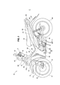
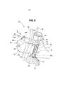
[0027] Como mostrado na figura 1, um veículo 10 é um veículo com selim. O veículo 10 inclui um tubo frontal 21 constituindo uma parte frontal de uma armação de corpo de veículo 20, uma ponte inferior 12 ligada a uma extremidade inferior do tubo frontal 21 e suportando extremidades superiores dos garfos frontais direito e esquerdo 11L, uma roda frontal 14 suportada pelos garfos frontais 11L e tendo uma parte superior da mesma coberta por um para-lama frontal 13, um dispositivo de freio 15 fornecido em um dos garfos frontais 11L para frear a roda frontal 14, e um dispositivo de detecção de velocidade de veículo 16 fornecido na proximidade do dispositivo de freio 15 para detectar a velocidade do veículo 10.[0027] As shown in figure 1, a
[0028] O veículo 10 ainda inclui um apoio de cobertura frontal 30 fixado ao tubo frontal 21 e se estendendo na direção da frente do veículo, uma cobertura frontal 41 montada no apoio da cobertura frontal 30 para cobrir uma parte frontal do tubo frontal 21, lâmpadas 51L encaixadas na cobertura frontal 41 para emitir luz em direção à frente do veículo, uma cobertura de guidão 42 para cobrir o guidão 17, e um medidor 52 disposto na cobertura de guidão 42 para exibir informação de velocidade de veículo transmitida a partir do dispositivo de detecção de velocidade do veículo 16.[0028] The
[0029] A armação de corpo de veículo 20 inclui uma armação principal 22 se estendendo de forma oblíqua para trás e para baixo a partir do tubo frontal 21, e um trilho de assento 23 se estendendo de forma oblíqua para trás e para cima a partir de uma extremidade traseira da armação principal 22 e suportando um assento 53 diretamente ou indiretamente.[0029]
[0030] Uma unidade de energia 60 é montada na armação principal 22. A unidade de energia 60 é composta por um motor 61 e uma transmissão 62. Um membro de suspensão 63 é conectado de modo balançante a uma parte traseira da unidade de energia 60, e uma roda traseira 64 é suportada de maneira rotativa através de uma extremidade traseira do membro de suspensão 63. A saída do motor 61 é transmitida para a roda traseira 64 através da transmissão 62. Ainda, uma unidade de amortecedor 65 é fornecida entre uma parte traseira do membro de suspensão 63 e o trilho de assento 23 para absorver um impacto aplicado à roda traseira 64.[0030] A
[0031] Uma unidade de farol traseiro 66 é fornecida em uma parte traseira do trilho de assento 23. Um para-lama traseiro 67 é disposto abaixo da unidade de farol traseiro 66 para cobrir partes traseiras e superiores da roda traseira 64. O veículo 10 ainda inclui uma cobertura de corpo de veículo 40 cobrindo a armação de corpo de veículo 20 etc.[0031] A
[0032] A cobertura de corpo de veículo 40 inclui a cobertura frontal 41 cobrindo pelo menos parte do tubo frontal 21, a cobertura de guidão 42 cobrindo o guidão 17, uma cobertura de armação principal 43 cobrindo uma parte superior da armação principal 22, uma cobertura lateral da armação principal 44 ligada à cobertura de armação principal 43 e cobrindo partes laterais do veículo 10, e uma cobertura traseira 45 ligada à cobertura de armação principal 43 e cobrindo as partes laterais e uma parte traseira do veículo.[0032] The
[0033] A seguir será descrita uma aparência externa do veículo na vista frontal.[0033] Next, an external appearance of the vehicle in the front view will be described.
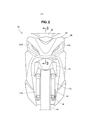
[0034] Como mostrado na figura 2, a cobertura frontal 41 é fornecida com as lâmpadas esquerda e direita 51L, 51R ("R" e "L" indicam respectivamente "direito" e "esquerdo", e o mesmo se aplica daqui em diante). O para-lama frontal 13 é localizado dentro de uma abertura formada em um lado inferior da cobertura frontal 41. O garfo frontal esquerdo e direito 11L, 11R se estende para baixo a partir do para-lama frontal 13, e a roda dianteira 14 é suportada pelas extremidades inferiores do garfo frontal esquerdo e direito 11L, 11R. O dispositivo de freio 15 é fornecido no garfo frontal 11L, e o dispositivo de detecção de velocidade do veículo 16 é disposto em uma posição na proximidade do dispositivo de freio 15 e mais próximo a um centro de rotação da roda frontal 14 do que o dispositivo de freio 15.[0034] As shown in figure 2, the
[0035] A seguir serão descritas partes essenciais do veículo de acordo com a presente invenção com referência a uma vista em seção transversal.[0035] In the following, essential parts of the vehicle according to the present invention will be described with reference to a cross-sectional view.
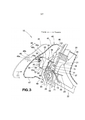
[0036] Como mostrado na figura 3, o tubo frontal 21 é fornecido com uma porção de montagem de apoio 24 na parte frontal do mesmo para montar sobre o mesmo o apoio de cobertura frontal 30. O apoio de cobertura frontal 30 é fixado à porção de montagem de apoio 24 com parafusos 71.[0036] As shown in Figure 3, the
[0037] O apoio de cobertura frontal 30 inclui uma seção de fixação 31 fixada à porção de montagem de apoio 24, uma seção cilíndrica 34 localizada na frente da seção de fixação 31 e formada em um formato cilíndrico tendo partes inferiores e superiores 32,33 da mesma abertas, uma parte frontal 35 localizada na frente da seção cilíndrica 34 e formada para suportar a cobertura frontal 41, uma seção de guia 36a formada para se estender substancialmente horizontalmente a partir de uma extremidade superior da parte frontal 35 à parte superior 32, e uma parede inferior 33a formada para se estender a partir de uma extremidade inferior da parte frontal 35 para uma seção cilíndrica 34. Com a seção de guia 36a localizada a frente de uma extremidade superior da seção cilíndrica e a parede inferior 33a localizada a frente de uma extremidade inferior da seção cilíndrica 34, um lado frontal da seção cilíndrica 34 é reforçado, pelo meio do qual a seção cilíndrica 34 pode ter uma rigidez aumentada. Ainda, a seção de fixação 31 é formada em um formato de placa e um formato retangular alongado em uma direção vertical ao longo do tubo frontal 21, e desempenha um papel como uma viga reforçando um lado traseiro da seção cilíndrica 34.[0037] The
[0038] Uma mangueira de freio 54 para transmitir uma força operacional do operador 18 ao dispositivo de freio 15 é disposta dentro da cobertura frontal 41. Mais especificamente, a mangueira de freio 54 é dirigida para entrar a partir de cima do tubo frontal 21 dentro de uma abertura superior 46 da cobertura frontal 41, passa através do interior da seção cilíndrica 34 do apoio de cobertura frontal 30, e emerge a partir de uma abertura inferior 48 formada em uma face inferior 47 da cobertura frontal 41 para se estender para baixo.[0038] A
[0039] Um cabo de medidor 55 para transmitir um sinal a partir do dispositivo de detecção de velocidade de veículo 16 para o medidor 52 é disposto dentro da cobertura frontal 41. O apoio de cobertura frontal 30 é fornecido com uma porção de retenção 37 para reter o cabo de medidor 55. Mais especificamente, o cabo de medidor 55 inserido a partir de cima do tubo frontal 21 para dentro da abertura superior 46 da cobertura frontal 41 é mantido pelo apoio de cobertura frontal 30 e pela porção de retenção 37. O cabo de medidor 55 então passa através de uma seção de gancho 25 fornecida em uma parte inferior do tubo frontal 21, e emerge a partir da abertura inferior 48 formada na face inferior 47 da cobertura frontal 41 para se estender para baixo. O cabo de medidor 55 é dirigido dessa maneira.[0039] A
[0040] O apoio de cobertura frontal 30 ainda inclui uma seção de retenção auxiliar 38 formada integralmente com a mesma para reter um conector 56 como um dos componentes auxiliares. O conector 56 é formado para conexão com um chicote 57 se estendendo a partir das lâmpadas 51L, 51R, e é fornecido a um chicote de fonte de energia 58 disposto no veículo 10. O chicote de fornecimento de energia 58 se estendendo para baixo a partir do conector 56 é mantido por um grampo 72 fornecido ao apoio de cobertura frontal 30, e passa através da seção de gancho 25.[0040] The
[0041] Uma buzina 73 é presa a uma parte inferior da porção de montagem de apoio 24. Um chicote 74 para a buzina 73 se estende a partir da buzina 73, e é também passado através da seção de gancho 25.[0041] A
[0042] O apoio de cobertura frontal 30 é fornecido com um ilhó 39 na parte frontal 35 do mesmo. A cobertura frontal 41 possui uma projeção 49 formada em um lado interno da mesma, e a projeção 49 é inserida dentro do ilhó 39.[0042] The
[0043] A cobertura frontal 41 ainda possui uma barra de guia 49b formada no lado interno da mesma e se projetando na direção do apoio de cobertura frontal 30. A barra de guia 49b e a seção de guia 36a do apoio de cobertura frontal 30 juntas constituem um meio-guia 36.[0043] The
[0044] A seguir será descrito como a cobertura frontal 41 é montada.[0044] The following describes how the
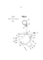
[0045] A cobertura frontal 41 mostrada por uma linha imaginária é movida como indicado pela seta (1). A barra de guia 49b mostrada pela linha imaginária é colada em contato com a seção de guia 36a do apoio de cobertura frontal 30, e a cobertura frontal 41 mostrada pela linha imaginária é desse modo guiada. A projeção 49 mostrada pela linha imaginária é inserida dentro do ilhó 39. A projeção 49 possui uma parte de assento 49a formada em uma extremidade de base da mesma, e a parte de assento 49a encosta no ilhó 39, desse modo a projeção 49 e a barra de guia 49b são paradas nas posições mostradas por uma linha sólida. Assim, com os meios de guia 36, a cobertura frontal 41 pode ser facilmente montada no apoio de cobertura frontal 30.[0045] The
[0046] Na presente modalidade, a mangueira de freio 54 é conectada ao dispositivo de freio 15, no entanto, ela não é tão limitada, e um cabo de freio 54 pode ser usado dependendo de um tipo do dispositivo de freio 15. Por conveniência, a modalidade é explicada daqui em diante no caso em que a mangueira de freio 54 é usada.[0046] In the present embodiment, the
[0047] A seguir será descrito como o apoio de cobertura frontal 30 é fixado e a mangueira de freio 54 é disposta, com referência a uma vista de plano.[0047] It will be described below how the
[0048] Como mostrado na figura 4, uma porca 26 é fornecida na porção de montagem de apoio 24 do tubo frontal 21. A seção de fixação 31 do apoio de cobertura frontal 30 é fixada à porca 26 com o parafuso 71, e o apoio de cobertura frontal 30 é desse modo fixado ao tubo frontal 21.[0048] As shown in Figure 4, a
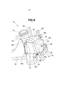
[0049] A seção cilíndrica 34 é composta de uma parte de base 34a no lado traseiro, e uma parte de abertura/fechamento 34b no lado frontal. O apoio de cobertura frontal 30 possui uma dobradiça em formato de flange 34c, e um flange 34d oposto à dobradiça 34c com a seção cilíndrica 34 entre os mesmos.[0049] The
[0050] Em um estado no qual a parte de abertura/fechamento 34b [e aberta, a mangueira de freio 54 é colocada dentro da seção cilíndrica 34 como indicado pela seta (2). Então, a parte de abertura/fechamento 34b é fechada, e a dobradiça 34c é fixada na parte de base 34a com o parafuso 75. A mangueira de freio 54 é, então, disposta para passar através da seção cilíndrica 34.[0050] In a state in which the opening/
[0051] O estado da mangueira de freio 54 passando através do apoio de cobertura frontal 30 será descrito em detalhes abaixo.[0051] The condition of the
[0052] Como mostrado na figura 5, a mangueira de freio é disposta para passar através da seção cilíndrica 34 do apoio de cobertura frontal 30 na direção vertical. Uma vez que o apoio de cobertura frontal 30 é disposto adjacente ao tubo frontal 21, a mangueira de freio 54 que passa através da seção cilíndrica 34 é dirigida adjacente ao tubo frontal 21. Como resultado, o comprimento da mangueira de freio 54 pode ser minimizado.[0052] As shown in Figure 5, the brake hose is arranged to pass through the
[0053] Quando a roda frontal 14 é dirigida, a mangueira de freio 54 é movida. No entanto, uma vez que a seção cilíndrica 34 é formada para ser maior do que uma extensão flexível da mangueira de freio 54, a mangueira de freio 54 pode ser contida apropriadamente.[0053] When the
[0054] Uma vez que o cabo de medidor 55 é retido entre o tubo frontal 21 e a porção de retenção 37, o cabo de medidor 55 é também dirigido adjacente ao tubo frontal 21, e o comprimento do cabo de medidor 55 pode também ser minimizado. Ainda, com a porção de retenção 37, não há necessidade de fornecer um membro adicional para reter o cabo de medidor 55, e assim o número de componentes pode ser reduzido.[0054] Since the
[0055] O apoio de cobertura frontal 30 inclui a seção de fixação 31 fixada na porção de montagem de apoio 24, a parte de base 34a localizada na frente da seção de fixação 31, um flange superior 34e formado em uma extremidade superior da parte de base 34a, a parte de abertura/fechamento localizada na frente da parte de base 34a e formada em formato curvado, a dobradiça em formato de flange 34c formada em uma extremidade em uma direção de largura de veículo da parte de abertura/fechamento 34b para ser alongada na direção vertical, o flange 34d formado na outra extremidade na direção da largura de veículo da parte de abertura/fechamento 34b para ser alongada na direção vertical, e a parte frontal em formato de caixa 35 localizada na frente da parte de abertura/fechamento 34b.[0055] The
[0056] A parte frontal em formato de caixa 35 inclui uma parede frontal 35a, a seção de guia 36a formada em uma extremidade superior da parede frontal 35a, uma parede lateral 35b formada em uma extremidade esquerda da parede frontal 35a, uma parede lateral 35c (figura 6) formada em uma extremidade direita da parede frontal 35a, e a parte inferior (figura 3) formada em uma extremidade inferior da parede frontal 35a. A parte frontal 35 é formada em um formato de caixa tendo cinco faces da parede frontal 35a, seção de guia 36a, parede lateral 35b parede lateral 35c, e uma parede inferior 33a fechada, e o lado traseiro da mesma aberto. Com a parte frontal em formato de caixa 35 localizada na frente da parte de abertura/fechamento 34b, a rigidez da seção cilíndrica 34 no lado frontal pode ser aumentada.[0056] The box-shaped
[0057] Ainda, com a dobradiça em formato de flange 34c formada no lado esquerdo da seção cilíndrica 34, o flange 34d formado no lado direito da seção cilíndrica 34, e o flange superior 34e formado na extremidade superior da seção cilíndrica 34, uma periferia da seção cilíndrica 34 pode ser reforçada. Uma vez que a seção cilíndrica 34 é localizada no meio de uma direção traseira-frontal do apoio de cobertura frontal 30, e a periferia da mesma é assim reforçada, a rigidez de todo apoio de cobertura frontal 30 pode ser aumentada, por meio do que a cobertura frontal 41 pode ser retida firmemente.[0057] Further, with the flange-shaped
[0058] Ao fixar a dobradiça em formato de flange 34c com um parafuso 76, a dobradiça 34c pode ser reforçada no estado em que a seção cilíndrica 34 é fechada.[0058] By fixing the flange-shaped
[0059] Como mostrado na figura 6, a mangueira de freio 54 é dirigida para passar através seção cilíndrica 34. O apoio de cobertura frontal 30 é formado de resina, de modo que a mangueira de freio 54 pode ser protegida mesmo quando a mangueira de freio 54 entra em contato com a seção cilíndrica 34. Ao fixar o flange 34d com dois parafusos 75, o flange 34d pode ser firmemente fixado mesmo sendo formado de resina.[0059] As shown in Figure 6, the
[0060] A porção de montagem de apoio 24 ainda possui em uma extremidade inferior da mesma uma parte em formato de L 24a formada em um formato de L, e a porção de montagem de apoio 24 pode ser desse modo soldada firmemente ao tubo frontal 21 na direção de largura de veículo.[0060] The
[0061] Como mostrado na figura 7, a porção de montagem de apoio 24 é formada alongada na direção vertical ao longo do tubo frontal 21, e soldada ao tubo frontal 21. A porção de montagem de apoio 24 pode ser, portanto, soldada firmemente ao tubo frontal 21 na direção vertical. Adicionalmente, a cobertura frontal 41 (figura 3) pode ser suportada firmemente na direção vertical através do apoio de cobertura frontal 30.[0061] As shown in Figure 7, the
[0062] Ao formar a parede frontal 35a em uma face substancialmente vertical, a quantidade de projeção da mesma em uma direção longitudinal do veículo pode ser suprimida. Ainda, ao dispor o apoio de cobertura frontal 30 tendo a seção cilíndrica 34 adjacente ao tubo frontal 21, é possível reter a mangueira de freio 54 na extensão flexível da mesma, enquanto suportando a cobertura frontal 41, desse modo a parte frontal do veículo 10 pode se tornar compacta.[0062] By forming the
[0063] Na estrutura de parte frontal do veículo com selim de acordo com a presente invenção, embora a modalidade tenha sido explicada no caso em que apenas a mangueira de freio é disposta para passar através da seção cilíndrica, não é assim limitada, e cabos tendo extensões flexíveis, tais como o cabo de medidor e o chicote, podem ser dispostos para passar através da seção cilíndrica.[0063] In the saddle-mounted vehicle front frame according to the present invention, although the embodiment has been explained in the case where only the brake hose is arranged to pass through the cylindrical section, it is not so limited, and cables having flexible extensions, such as the meter cable and harness, can be arranged to pass through the cylindrical section.
[0064] A estrutura de parte frontal da presente invenção é adequada para o uso em veículos com selim. Caracteres de Referência 10 ... veículo (veículo com selim), 14 ... roda frontal, 15 ... dispositivo de freio, 16 ... dispositivo de detecção de velocidade de veículo, 18 ... operador, 20 ... armação de corpo de veículo, 21 ... tubo frontal, 30 ... apoio de cobertura frontal, 34 ... seção cilíndrica, 36 ... meio-guia, 38 seção de retenção auxiliar, 39 ... ilhó, 41 ... cobertura frontal, 49 ... projeção, 51L, 51R ... lâmpadas, 52 ... medidor, 54 ... mangueira de freio (cabo de freio), 55 ... cabo de medidor, 56 ... componente auxiliar (conector), 57 ... chicote[0064] The front frame of the present invention is suitable for use in saddled vehicles.
Claims (9)
Applications Claiming Priority (3)
| Application Number | Priority Date | Filing Date | Title |
|---|---|---|---|
| JP2013-038992 | 2013-02-28 | ||
| JP2013038992 | 2013-02-28 | ||
| PCT/JP2014/054298 WO2014132913A1 (en) | 2013-02-28 | 2014-02-24 | Structure for front part of saddled vehicle |
Publications (2)
| Publication Number | Publication Date |
|---|---|
| BR112015020552A2 BR112015020552A2 (en) | 2017-07-18 |
| BR112015020552B1 true BR112015020552B1 (en) | 2021-12-07 |
Family
ID=51428178
Family Applications (1)
| Application Number | Title | Priority Date | Filing Date |
|---|---|---|---|
| BR112015020552-6A BR112015020552B1 (en) | 2013-02-28 | 2014-02-24 | STRUCTURE FOR FRONT PART OF VEHICLE WITH SADDLE |
Country Status (8)
| Country | Link |
|---|---|
| EP (1) | EP2962924A4 (en) |
| JP (1) | JP6043863B2 (en) |
| CN (1) | CN105026250B (en) |
| AR (1) | AR094889A1 (en) |
| BR (1) | BR112015020552B1 (en) |
| MY (1) | MY173021A (en) |
| PH (1) | PH12015501910A1 (en) |
| WO (1) | WO2014132913A1 (en) |
Families Citing this family (7)
| Publication number | Priority date | Publication date | Assignee | Title |
|---|---|---|---|---|
| JP2951697B2 (en) | 1990-07-05 | 1999-09-20 | 旭化成工業株式会社 | Polyamide resin composition for molding |
| JP6356358B2 (en) * | 2015-03-31 | 2018-07-11 | 本田技研工業株式会社 | Position light structure for motorcycles |
| CA2961468A1 (en) * | 2016-03-28 | 2017-09-28 | Honda Motor Co., Ltd. | Saddle-riding-type vehicle cable support structure |
| WO2018029734A1 (en) * | 2016-08-08 | 2018-02-15 | 本田技研工業株式会社 | Vehicle |
| EP3480099A4 (en) * | 2016-09-30 | 2019-08-28 | Honda Motor Co., Ltd. | Interlocking brake support structure for saddle-type vehicle |
| JP6708688B2 (en) * | 2018-04-02 | 2020-06-10 | 本田技研工業株式会社 | Harness guide structure for saddle type vehicles |
| JP7563094B2 (en) * | 2020-10-09 | 2024-10-08 | スズキ株式会社 | Rectifier Support Structure |
Family Cites Families (11)
| Publication number | Priority date | Publication date | Assignee | Title |
|---|---|---|---|---|
| JPS6131907Y2 (en) * | 1981-01-13 | 1986-09-17 | ||
| JPS59111785U (en) * | 1983-01-19 | 1984-07-27 | 本田技研工業株式会社 | Front visor device for motorcycles |
| JPS6339097U (en) * | 1986-08-30 | 1988-03-14 | ||
| JPH01103590A (en) * | 1987-10-19 | 1989-04-20 | Suzuki Motor Co Ltd | Battery storage device for scooter |
| JP3153044B2 (en) * | 1993-04-17 | 2001-04-03 | 本田技研工業株式会社 | Motorcycle headlight mounting structure |
| JPH1111369A (en) * | 1997-06-23 | 1999-01-19 | Suzuki Motor Corp | Headlamp support structure for motorcycles, etc. |
| JP3457303B2 (en) | 2002-08-23 | 2003-10-14 | 本田技研工業株式会社 | Mounting structure of front top cover for motorcycle |
| JP3813630B2 (en) * | 2003-02-21 | 2006-08-23 | ヤマハ発動機株式会社 | Saddle riding |
| JP4743535B2 (en) * | 2006-09-29 | 2011-08-10 | 本田技研工業株式会社 | Brake equipment for motorcycles |
| JP2009179260A (en) * | 2008-01-31 | 2009-08-13 | Honda Motor Co Ltd | Interlocking brake device for motorcycles |
| JP5171554B2 (en) * | 2008-10-31 | 2013-03-27 | 本田技研工業株式会社 | Motorcycle |
-
2014
- 2014-02-24 BR BR112015020552-6A patent/BR112015020552B1/en active IP Right Grant
- 2014-02-24 WO PCT/JP2014/054298 patent/WO2014132913A1/en not_active Ceased
- 2014-02-24 JP JP2015502905A patent/JP6043863B2/en not_active Expired - Fee Related
- 2014-02-24 CN CN201480010895.5A patent/CN105026250B/en active Active
- 2014-02-24 EP EP14757358.8A patent/EP2962924A4/en not_active Withdrawn
- 2014-02-24 MY MYPI2015702843A patent/MY173021A/en unknown
- 2014-02-26 AR ARP140100597A patent/AR094889A1/en active IP Right Grant
-
2015
- 2015-08-28 PH PH12015501910A patent/PH12015501910A1/en unknown
Also Published As
| Publication number | Publication date |
|---|---|
| WO2014132913A1 (en) | 2014-09-04 |
| JPWO2014132913A1 (en) | 2017-02-02 |
| EP2962924A1 (en) | 2016-01-06 |
| CN105026250A (en) | 2015-11-04 |
| PH12015501910B1 (en) | 2016-01-04 |
| BR112015020552A2 (en) | 2017-07-18 |
| EP2962924A4 (en) | 2016-11-23 |
| MY173021A (en) | 2019-12-19 |
| AR094889A1 (en) | 2015-09-02 |
| JP6043863B2 (en) | 2016-12-14 |
| PH12015501910A1 (en) | 2016-01-04 |
| CN105026250B (en) | 2018-02-16 |
Similar Documents
| Publication | Publication Date | Title |
|---|---|---|
| BR112015020552B1 (en) | STRUCTURE FOR FRONT PART OF VEHICLE WITH SADDLE | |
| CN104203737A (en) | Saddled vehicle | |
| BR112018069479B1 (en) | MOTORCYCLE | |
| BR102016003638B1 (en) | REAR STRUCTURE FOR MOUNT TYPE VEHICLE | |
| JP6540371B2 (en) | Front body structure of a motorcycle | |
| CN104870302B (en) | Straddle riding type vehicle | |
| BR102022005739A2 (en) | VEHICLE | |
| CN102120474A (en) | Turn signal device for saddle-ride type vehicle | |
| ITTO990123A1 (en) | SUPPORT STRUCTURE FOR A VEHICLE BODY COVER ELEMENT. | |
| US10850790B2 (en) | Straddle-type vehicle | |
| BR102012019905B1 (en) | body-back structure in mounted driving type vehicle | |
| BR102012022555B1 (en) | riding type vehicle | |
| BRPI1103034B1 (en) | SEAT-MOUNTED VEHICLE | |
| BRPI0905049B1 (en) | VEHICLE USE MEASURING DEVICE | |
| JP5566654B2 (en) | Motorcycle wiring system | |
| JP2010100102A (en) | Motorcycle | |
| JP2005119609A (en) | Scooter type motorcycle | |
| JP7352726B2 (en) | vehicle | |
| BR102024022094A2 (en) | SADDLE-MOUNTED DRIVING VEHICLE | |
| CN215285111U (en) | straddle vehicle | |
| BR102020021182B1 (en) | VEHICLE FOR DRIVING WHILE MOUNTING ON A SADDLE | |
| BR102023021157A2 (en) | PROTECTIVE FRAME FOR HANDLEBAR LOCKING PIN | |
| BR112019014573B1 (en) | FRONT/REAR INTERLOCK BRAKING DEVICE FOR SADDLE TYPE VEHICLES | |
| KR101014488B1 (en) | Automotive high mounted stop lamps mounted on roof panels | |
| BR102022008935B1 (en) | VEHICLE CABLE ROUTING STRUCTURE WITH SADDLE |
Legal Events
| Date | Code | Title | Description |
|---|---|---|---|
| B06F | Objections, documents and/or translations needed after an examination request according [chapter 6.6 patent gazette] | ||
| B06U | Preliminary requirement: requests with searches performed by other patent offices: procedure suspended [chapter 6.21 patent gazette] | ||
| B09A | Decision: intention to grant [chapter 9.1 patent gazette] | ||
| B16A | Patent or certificate of addition of invention granted [chapter 16.1 patent gazette] |
Free format text: PRAZO DE VALIDADE: 20 (VINTE) ANOS CONTADOS A PARTIR DE 24/02/2014, OBSERVADAS AS CONDICOES LEGAIS. |