BR112015011388B1 - OPTICAL EFFECT LAYER (OEL), USE AND PROCESS FOR THE PRODUCTION OF THE SAME, MAGNETIC FIELD GENERATOR DEVICE, USE OF THE SAME, PRINT SET, OPTICAL EFFECT COATED SUBSTRATE (OEC), USE OF THE SAME, AND SAFETY DOCUMENT - Google Patents
OPTICAL EFFECT LAYER (OEL), USE AND PROCESS FOR THE PRODUCTION OF THE SAME, MAGNETIC FIELD GENERATOR DEVICE, USE OF THE SAME, PRINT SET, OPTICAL EFFECT COATED SUBSTRATE (OEC), USE OF THE SAME, AND SAFETY DOCUMENT Download PDFInfo
- Publication number
- BR112015011388B1 BR112015011388B1 BR112015011388-5A BR112015011388A BR112015011388B1 BR 112015011388 B1 BR112015011388 B1 BR 112015011388B1 BR 112015011388 A BR112015011388 A BR 112015011388A BR 112015011388 B1 BR112015011388 B1 BR 112015011388B1
- Authority
- BR
- Brazil
- Prior art keywords
- oel
- loop
- magnetic
- axis
- optical effect
- Prior art date
Links
- 230000005291 magnetic effect Effects 0.000 title claims abstract description 383
- 239000000758 substrate Substances 0.000 title claims abstract description 137
- 230000003287 optical effect Effects 0.000 title claims abstract description 123
- 238000000034 method Methods 0.000 title claims abstract description 36
- 230000008569 process Effects 0.000 title claims abstract description 33
- 238000004519 manufacturing process Methods 0.000 title claims description 9
- 239000002245 particle Substances 0.000 claims abstract description 231
- 239000008199 coating composition Substances 0.000 claims abstract description 125
- 239000000463 material Substances 0.000 claims abstract description 69
- 239000011230 binding agent Substances 0.000 claims abstract description 21
- 239000000049 pigment Substances 0.000 claims description 64
- 239000000203 mixture Substances 0.000 claims description 40
- 230000005855 radiation Effects 0.000 claims description 19
- 239000006249 magnetic particle Substances 0.000 claims description 17
- 239000007787 solid Substances 0.000 claims description 17
- 239000010409 thin film Substances 0.000 claims description 10
- 239000004986 Cholesteric liquid crystals (ChLC) Substances 0.000 claims description 7
- 230000015572 biosynthetic process Effects 0.000 claims description 7
- 230000002093 peripheral effect Effects 0.000 claims description 4
- 230000036962 time dependent Effects 0.000 claims description 2
- 238000007639 printing Methods 0.000 abstract description 23
- 230000001419 dependent effect Effects 0.000 abstract description 10
- 239000010410 layer Substances 0.000 description 93
- XEEYBQQBJWHFJM-UHFFFAOYSA-N Iron Chemical compound [Fe] XEEYBQQBJWHFJM-UHFFFAOYSA-N 0.000 description 22
- PXHVJJICTQNCMI-UHFFFAOYSA-N Nickel Chemical compound [Ni] PXHVJJICTQNCMI-UHFFFAOYSA-N 0.000 description 21
- 230000000694 effects Effects 0.000 description 17
- 238000002310 reflectometry Methods 0.000 description 17
- 230000002745 absorbent Effects 0.000 description 12
- 239000002250 absorbent Substances 0.000 description 12
- 230000008859 change Effects 0.000 description 12
- 238000000576 coating method Methods 0.000 description 12
- 239000000976 ink Substances 0.000 description 12
- 150000001875 compounds Chemical class 0.000 description 11
- 229910052742 iron Inorganic materials 0.000 description 10
- 230000005670 electromagnetic radiation Effects 0.000 description 9
- -1 hematite (Fe2O3) Chemical class 0.000 description 9
- 239000011248 coating agent Substances 0.000 description 8
- 238000001723 curing Methods 0.000 description 8
- 229910052759 nickel Inorganic materials 0.000 description 8
- 239000012798 spherical particle Substances 0.000 description 8
- 239000000126 substance Substances 0.000 description 8
- 238000006243 chemical reaction Methods 0.000 description 7
- 239000011651 chromium Substances 0.000 description 7
- 239000011247 coating layer Substances 0.000 description 7
- 229910017052 cobalt Inorganic materials 0.000 description 7
- 239000010941 cobalt Substances 0.000 description 7
- GUTLYIVDDKVIGB-UHFFFAOYSA-N cobalt atom Chemical compound [Co] GUTLYIVDDKVIGB-UHFFFAOYSA-N 0.000 description 7
- 238000007650 screen-printing Methods 0.000 description 7
- 229910052751 metal Inorganic materials 0.000 description 6
- 239000002184 metal Substances 0.000 description 6
- 229910001172 neodymium magnet Inorganic materials 0.000 description 6
- 239000003973 paint Substances 0.000 description 6
- 239000004033 plastic Substances 0.000 description 6
- 229920003023 plastic Polymers 0.000 description 6
- 230000003068 static effect Effects 0.000 description 6
- 239000000654 additive Substances 0.000 description 5
- 238000004132 cross linking Methods 0.000 description 5
- 238000001035 drying Methods 0.000 description 5
- 230000005293 ferrimagnetic effect Effects 0.000 description 5
- 239000012530 fluid Substances 0.000 description 5
- 230000001788 irregular Effects 0.000 description 5
- 238000003847 radiation curing Methods 0.000 description 5
- VYPSYNLAJGMNEJ-UHFFFAOYSA-N Silicium dioxide Chemical compound O=[Si]=O VYPSYNLAJGMNEJ-UHFFFAOYSA-N 0.000 description 4
- 239000003795 chemical substances by application Substances 0.000 description 4
- 230000003098 cholesteric effect Effects 0.000 description 4
- 238000005516 engineering process Methods 0.000 description 4
- 230000001747 exhibiting effect Effects 0.000 description 4
- 230000005294 ferromagnetic effect Effects 0.000 description 4
- ORUIBWPALBXDOA-UHFFFAOYSA-L magnesium fluoride Chemical compound [F-].[F-].[Mg+2] ORUIBWPALBXDOA-UHFFFAOYSA-L 0.000 description 4
- 238000006116 polymerization reaction Methods 0.000 description 4
- 239000011241 protective layer Substances 0.000 description 4
- 239000002904 solvent Substances 0.000 description 4
- 230000000007 visual effect Effects 0.000 description 4
- VYZAMTAEIAYCRO-UHFFFAOYSA-N Chromium Chemical compound [Cr] VYZAMTAEIAYCRO-UHFFFAOYSA-N 0.000 description 3
- 229940126062 Compound A Drugs 0.000 description 3
- 229920000742 Cotton Polymers 0.000 description 3
- NLDMNSXOCDLTTB-UHFFFAOYSA-N Heterophylliin A Natural products O1C2COC(=O)C3=CC(O)=C(O)C(O)=C3C3=C(O)C(O)=C(O)C=C3C(=O)OC2C(OC(=O)C=2C=C(O)C(O)=C(O)C=2)C(O)C1OC(=O)C1=CC(O)=C(O)C(O)=C1 NLDMNSXOCDLTTB-UHFFFAOYSA-N 0.000 description 3
- 238000003848 UV Light-Curing Methods 0.000 description 3
- 239000012790 adhesive layer Substances 0.000 description 3
- 239000000956 alloy Substances 0.000 description 3
- 229910045601 alloy Inorganic materials 0.000 description 3
- 229910052782 aluminium Inorganic materials 0.000 description 3
- XAGFODPZIPBFFR-UHFFFAOYSA-N aluminium Chemical compound [Al] XAGFODPZIPBFFR-UHFFFAOYSA-N 0.000 description 3
- 229910052804 chromium Inorganic materials 0.000 description 3
- 239000002131 composite material Substances 0.000 description 3
- 239000010408 film Substances 0.000 description 3
- SZVJSHCCFOBDDC-UHFFFAOYSA-N iron(II,III) oxide Inorganic materials O=[Fe]O[Fe]O[Fe]=O SZVJSHCCFOBDDC-UHFFFAOYSA-N 0.000 description 3
- 239000007788 liquid Substances 0.000 description 3
- 239000000696 magnetic material Substances 0.000 description 3
- 230000005415 magnetization Effects 0.000 description 3
- WPBNNNQJVZRUHP-UHFFFAOYSA-L manganese(2+);methyl n-[[2-(methoxycarbonylcarbamothioylamino)phenyl]carbamothioyl]carbamate;n-[2-(sulfidocarbothioylamino)ethyl]carbamodithioate Chemical compound [Mn+2].[S-]C(=S)NCCNC([S-])=S.COC(=O)NC(=S)NC1=CC=CC=C1NC(=S)NC(=O)OC WPBNNNQJVZRUHP-UHFFFAOYSA-L 0.000 description 3
- 230000007246 mechanism Effects 0.000 description 3
- 229910001092 metal group alloy Inorganic materials 0.000 description 3
- 229920000642 polymer Polymers 0.000 description 3
- 238000002360 preparation method Methods 0.000 description 3
- 238000005096 rolling process Methods 0.000 description 3
- 238000001228 spectrum Methods 0.000 description 3
- 238000012546 transfer Methods 0.000 description 3
- RYGMFSIKBFXOCR-UHFFFAOYSA-N Copper Chemical compound [Cu] RYGMFSIKBFXOCR-UHFFFAOYSA-N 0.000 description 2
- 239000004696 Poly ether ether ketone Substances 0.000 description 2
- 239000004952 Polyamide Substances 0.000 description 2
- 239000004698 Polyethylene Substances 0.000 description 2
- 239000004743 Polypropylene Substances 0.000 description 2
- 229920001131 Pulp (paper) Polymers 0.000 description 2
- QJVKUMXDEUEQLH-UHFFFAOYSA-N [B].[Fe].[Nd] Chemical compound [B].[Fe].[Nd] QJVKUMXDEUEQLH-UHFFFAOYSA-N 0.000 description 2
- 230000004913 activation Effects 0.000 description 2
- 239000000853 adhesive Substances 0.000 description 2
- 230000001070 adhesive effect Effects 0.000 description 2
- 239000003054 catalyst Substances 0.000 description 2
- 125000002091 cationic group Chemical group 0.000 description 2
- 229940090961 chromium dioxide Drugs 0.000 description 2
- IAQWMWUKBQPOIY-UHFFFAOYSA-N chromium(4+);oxygen(2-) Chemical compound [O-2].[O-2].[Cr+4] IAQWMWUKBQPOIY-UHFFFAOYSA-N 0.000 description 2
- AYTAKQFHWFYBMA-UHFFFAOYSA-N chromium(IV) oxide Inorganic materials O=[Cr]=O AYTAKQFHWFYBMA-UHFFFAOYSA-N 0.000 description 2
- 238000001816 cooling Methods 0.000 description 2
- 229910052802 copper Inorganic materials 0.000 description 2
- 239000010949 copper Substances 0.000 description 2
- 230000007423 decrease Effects 0.000 description 2
- 238000001514 detection method Methods 0.000 description 2
- 238000001704 evaporation Methods 0.000 description 2
- 230000008020 evaporation Effects 0.000 description 2
- 239000000835 fiber Substances 0.000 description 2
- 239000002657 fibrous material Substances 0.000 description 2
- 238000007647 flexography Methods 0.000 description 2
- 230000006870 function Effects 0.000 description 2
- 239000011521 glass Substances 0.000 description 2
- 238000007646 gravure printing Methods 0.000 description 2
- 239000003999 initiator Substances 0.000 description 2
- 239000011229 interlayer Substances 0.000 description 2
- 229910001635 magnesium fluoride Inorganic materials 0.000 description 2
- 150000002739 metals Chemical class 0.000 description 2
- 230000004048 modification Effects 0.000 description 2
- 238000012986 modification Methods 0.000 description 2
- 230000001590 oxidative effect Effects 0.000 description 2
- 230000036961 partial effect Effects 0.000 description 2
- 230000035699 permeability Effects 0.000 description 2
- 229920001652 poly(etherketoneketone) Polymers 0.000 description 2
- 229920002647 polyamide Polymers 0.000 description 2
- 229920000728 polyester Polymers 0.000 description 2
- 229920002530 polyetherether ketone Polymers 0.000 description 2
- 229920000573 polyethylene Polymers 0.000 description 2
- 229920000139 polyethylene terephthalate Polymers 0.000 description 2
- 239000005020 polyethylene terephthalate Substances 0.000 description 2
- 229920000098 polyolefin Polymers 0.000 description 2
- 229920001155 polypropylene Polymers 0.000 description 2
- 229920000915 polyvinyl chloride Polymers 0.000 description 2
- 230000001681 protective effect Effects 0.000 description 2
- 150000003254 radicals Chemical class 0.000 description 2
- 239000000377 silicon dioxide Substances 0.000 description 2
- 235000012239 silicon dioxide Nutrition 0.000 description 2
- 239000011343 solid material Substances 0.000 description 2
- 229920001169 thermoplastic Polymers 0.000 description 2
- 229920005992 thermoplastic resin Polymers 0.000 description 2
- 229920001187 thermosetting polymer Polymers 0.000 description 2
- 239000002966 varnish Substances 0.000 description 2
- 238000001429 visible spectrum Methods 0.000 description 2
- ODPYDILFQYARBK-UHFFFAOYSA-N 7-thiabicyclo[4.1.0]hepta-1,3,5-triene Chemical class C1=CC=C2SC2=C1 ODPYDILFQYARBK-UHFFFAOYSA-N 0.000 description 1
- 229910000531 Co alloy Inorganic materials 0.000 description 1
- 229910001313 Cobalt-iron alloy Inorganic materials 0.000 description 1
- VGGSQFUCUMXWEO-UHFFFAOYSA-N Ethene Chemical compound C=C VGGSQFUCUMXWEO-UHFFFAOYSA-N 0.000 description 1
- 239000005977 Ethylene Substances 0.000 description 1
- 206010073306 Exposure to radiation Diseases 0.000 description 1
- 229910000640 Fe alloy Inorganic materials 0.000 description 1
- PWHULOQIROXLJO-UHFFFAOYSA-N Manganese Chemical compound [Mn] PWHULOQIROXLJO-UHFFFAOYSA-N 0.000 description 1
- 240000000907 Musa textilis Species 0.000 description 1
- 229920002544 Olefin fiber Polymers 0.000 description 1
- 239000004642 Polyimide Substances 0.000 description 1
- 229920000265 Polyparaphenylene Polymers 0.000 description 1
- 239000004721 Polyphenylene oxide Substances 0.000 description 1
- 239000004775 Tyvek Substances 0.000 description 1
- 229920000690 Tyvek Polymers 0.000 description 1
- 239000011358 absorbing material Substances 0.000 description 1
- 238000010521 absorption reaction Methods 0.000 description 1
- 239000002253 acid Substances 0.000 description 1
- 150000007513 acids Chemical class 0.000 description 1
- 230000002730 additional effect Effects 0.000 description 1
- 230000000996 additive effect Effects 0.000 description 1
- 239000002671 adjuvant Substances 0.000 description 1
- 229910000828 alnico Inorganic materials 0.000 description 1
- 239000004411 aluminium Substances 0.000 description 1
- 239000002518 antifoaming agent Substances 0.000 description 1
- 230000000712 assembly Effects 0.000 description 1
- 238000000429 assembly Methods 0.000 description 1
- QVGXLLKOCUKJST-UHFFFAOYSA-N atomic oxygen Chemical compound [O] QVGXLLKOCUKJST-UHFFFAOYSA-N 0.000 description 1
- 229910052788 barium Inorganic materials 0.000 description 1
- DSAJWYNOEDNPEQ-UHFFFAOYSA-N barium atom Chemical compound [Ba] DSAJWYNOEDNPEQ-UHFFFAOYSA-N 0.000 description 1
- 230000008901 benefit Effects 0.000 description 1
- 230000005540 biological transmission Effects 0.000 description 1
- 210000000988 bone and bone Anatomy 0.000 description 1
- 229920002678 cellulose Polymers 0.000 description 1
- 239000001913 cellulose Substances 0.000 description 1
- 239000000919 ceramic Substances 0.000 description 1
- 238000010382 chemical cross-linking Methods 0.000 description 1
- 238000004140 cleaning Methods 0.000 description 1
- 239000006103 coloring component Substances 0.000 description 1
- 239000004020 conductor Substances 0.000 description 1
- 239000002537 cosmetic Substances 0.000 description 1
- 239000003431 cross linking reagent Substances 0.000 description 1
- 238000005034 decoration Methods 0.000 description 1
- 230000007812 deficiency Effects 0.000 description 1
- 238000000151 deposition Methods 0.000 description 1
- 230000008021 deposition Effects 0.000 description 1
- QDOXWKRWXJOMAK-UHFFFAOYSA-N dichromium trioxide Chemical compound O=[Cr]O[Cr]=O QDOXWKRWXJOMAK-UHFFFAOYSA-N 0.000 description 1
- 239000003814 drug Substances 0.000 description 1
- 229940079593 drug Drugs 0.000 description 1
- 239000000975 dye Substances 0.000 description 1
- 238000010891 electric arc Methods 0.000 description 1
- 238000010894 electron beam technology Methods 0.000 description 1
- 239000000945 filler Substances 0.000 description 1
- 239000006260 foam Substances 0.000 description 1
- 238000009472 formulation Methods 0.000 description 1
- 238000000227 grinding Methods 0.000 description 1
- 238000010438 heat treatment Methods 0.000 description 1
- 239000004615 ingredient Substances 0.000 description 1
- 239000003112 inhibitor Substances 0.000 description 1
- 230000000977 initiatory effect Effects 0.000 description 1
- 239000001023 inorganic pigment Substances 0.000 description 1
- UQSXHKLRYXJYBZ-UHFFFAOYSA-N iron oxide Inorganic materials [Fe]=O UQSXHKLRYXJYBZ-UHFFFAOYSA-N 0.000 description 1
- 235000013980 iron oxide Nutrition 0.000 description 1
- VBMVTYDPPZVILR-UHFFFAOYSA-N iron(2+);oxygen(2-) Chemical class [O-2].[Fe+2] VBMVTYDPPZVILR-UHFFFAOYSA-N 0.000 description 1
- LIKBJVNGSGBSGK-UHFFFAOYSA-N iron(3+);oxygen(2-) Chemical compound [O-2].[O-2].[O-2].[Fe+3].[Fe+3] LIKBJVNGSGBSGK-UHFFFAOYSA-N 0.000 description 1
- 230000009916 joint effect Effects 0.000 description 1
- 230000000670 limiting effect Effects 0.000 description 1
- 230000001050 lubricating effect Effects 0.000 description 1
- 238000004020 luminiscence type Methods 0.000 description 1
- 239000012762 magnetic filler Substances 0.000 description 1
- 239000002122 magnetic nanoparticle Substances 0.000 description 1
- 229910052748 manganese Inorganic materials 0.000 description 1
- 239000011572 manganese Substances 0.000 description 1
- 239000003550 marker Substances 0.000 description 1
- 239000011159 matrix material Substances 0.000 description 1
- QSHDDOUJBYECFT-UHFFFAOYSA-N mercury Chemical compound [Hg] QSHDDOUJBYECFT-UHFFFAOYSA-N 0.000 description 1
- 229910052753 mercury Inorganic materials 0.000 description 1
- 229910021645 metal ion Inorganic materials 0.000 description 1
- 238000003801 milling Methods 0.000 description 1
- 239000000178 monomer Substances 0.000 description 1
- 239000002086 nanomaterial Substances 0.000 description 1
- 239000003921 oil Substances 0.000 description 1
- 239000004767 olefin fiber Substances 0.000 description 1
- 238000001579 optical reflectometry Methods 0.000 description 1
- 239000012860 organic pigment Substances 0.000 description 1
- 229910052760 oxygen Inorganic materials 0.000 description 1
- 239000001301 oxygen Substances 0.000 description 1
- 239000005022 packaging material Substances 0.000 description 1
- 238000004806 packaging method and process Methods 0.000 description 1
- 235000011837 pasties Nutrition 0.000 description 1
- 230000000149 penetrating effect Effects 0.000 description 1
- 239000003504 photosensitizing agent Substances 0.000 description 1
- 230000000704 physical effect Effects 0.000 description 1
- 238000005240 physical vapour deposition Methods 0.000 description 1
- 239000002985 plastic film Substances 0.000 description 1
- 229920006255 plastic film Polymers 0.000 description 1
- 239000004014 plasticizer Substances 0.000 description 1
- 229920002492 poly(sulfone) Polymers 0.000 description 1
- 229920001230 polyarylate Polymers 0.000 description 1
- 239000004417 polycarbonate Substances 0.000 description 1
- 229920000515 polycarbonate Polymers 0.000 description 1
- 229920001721 polyimide Polymers 0.000 description 1
- 229920005594 polymer fiber Polymers 0.000 description 1
- 239000002861 polymer material Substances 0.000 description 1
- 239000003505 polymerization initiator Substances 0.000 description 1
- 230000000379 polymerizing effect Effects 0.000 description 1
- 229920006324 polyoxymethylene Polymers 0.000 description 1
- 229920001955 polyphenylene ether Polymers 0.000 description 1
- 229920006380 polyphenylene oxide Polymers 0.000 description 1
- 239000000843 powder Substances 0.000 description 1
- 238000012545 processing Methods 0.000 description 1
- 229910052761 rare earth metal Inorganic materials 0.000 description 1
- 150000002910 rare earth metals Chemical class 0.000 description 1
- 229920005989 resin Polymers 0.000 description 1
- 239000011347 resin Substances 0.000 description 1
- 230000004044 response Effects 0.000 description 1
- 230000000284 resting effect Effects 0.000 description 1
- 238000007761 roller coating Methods 0.000 description 1
- 239000005060 rubber Substances 0.000 description 1
- 230000015541 sensory perception of touch Effects 0.000 description 1
- 239000002356 single layer Substances 0.000 description 1
- 238000004513 sizing Methods 0.000 description 1
- 230000003595 spectral effect Effects 0.000 description 1
- 239000011029 spinel Substances 0.000 description 1
- 229910052596 spinel Inorganic materials 0.000 description 1
- 238000003860 storage Methods 0.000 description 1
- 239000004094 surface-active agent Substances 0.000 description 1
- 238000010998 test method Methods 0.000 description 1
- 239000004416 thermosoftening plastic Substances 0.000 description 1
- 239000002562 thickening agent Substances 0.000 description 1
- 230000001131 transforming effect Effects 0.000 description 1
- 238000002834 transmittance Methods 0.000 description 1
- 238000002211 ultraviolet spectrum Methods 0.000 description 1
- 238000001771 vacuum deposition Methods 0.000 description 1
- XLYOFNOQVPJJNP-UHFFFAOYSA-N water Substances O XLYOFNOQVPJJNP-UHFFFAOYSA-N 0.000 description 1
- 239000001993 wax Substances 0.000 description 1
- 229910000859 α-Fe Inorganic materials 0.000 description 1
Images


Classifications
-
- B—PERFORMING OPERATIONS; TRANSPORTING
- B05—SPRAYING OR ATOMISING IN GENERAL; APPLYING FLUENT MATERIALS TO SURFACES, IN GENERAL
- B05D—PROCESSES FOR APPLYING FLUENT MATERIALS TO SURFACES, IN GENERAL
- B05D3/00—Pretreatment of surfaces to which liquids or other fluent materials are to be applied; After-treatment of applied coatings, e.g. intermediate treating of an applied coating preparatory to subsequent applications of liquids or other fluent materials
- B05D3/20—Pretreatment of surfaces to which liquids or other fluent materials are to be applied; After-treatment of applied coatings, e.g. intermediate treating of an applied coating preparatory to subsequent applications of liquids or other fluent materials by magnetic fields
-
- B—PERFORMING OPERATIONS; TRANSPORTING
- B42—BOOKBINDING; ALBUMS; FILES; SPECIAL PRINTED MATTER
- B42D—BOOKS; BOOK COVERS; LOOSE LEAVES; PRINTED MATTER CHARACTERISED BY IDENTIFICATION OR SECURITY FEATURES; PRINTED MATTER OF SPECIAL FORMAT OR STYLE NOT OTHERWISE PROVIDED FOR; DEVICES FOR USE THEREWITH AND NOT OTHERWISE PROVIDED FOR; MOVABLE-STRIP WRITING OR READING APPARATUS
- B42D25/00—Information-bearing cards or sheet-like structures characterised by identification or security features; Manufacture thereof
- B42D25/30—Identification or security features, e.g. for preventing forgery
- B42D25/36—Identification or security features, e.g. for preventing forgery comprising special materials
- B42D25/369—Magnetised or magnetisable materials
-
- B—PERFORMING OPERATIONS; TRANSPORTING
- B05—SPRAYING OR ATOMISING IN GENERAL; APPLYING FLUENT MATERIALS TO SURFACES, IN GENERAL
- B05D—PROCESSES FOR APPLYING FLUENT MATERIALS TO SURFACES, IN GENERAL
- B05D3/00—Pretreatment of surfaces to which liquids or other fluent materials are to be applied; After-treatment of applied coatings, e.g. intermediate treating of an applied coating preparatory to subsequent applications of liquids or other fluent materials
- B05D3/20—Pretreatment of surfaces to which liquids or other fluent materials are to be applied; After-treatment of applied coatings, e.g. intermediate treating of an applied coating preparatory to subsequent applications of liquids or other fluent materials by magnetic fields
- B05D3/207—Pretreatment of surfaces to which liquids or other fluent materials are to be applied; After-treatment of applied coatings, e.g. intermediate treating of an applied coating preparatory to subsequent applications of liquids or other fluent materials by magnetic fields post-treatment by magnetic fields
-
- B—PERFORMING OPERATIONS; TRANSPORTING
- B41—PRINTING; LINING MACHINES; TYPEWRITERS; STAMPS
- B41M—PRINTING, DUPLICATING, MARKING, OR COPYING PROCESSES; COLOUR PRINTING
- B41M3/00—Printing processes to produce particular kinds of printed work, e.g. patterns
- B41M3/14—Security printing
- B41M3/148—Transitory images, i.e. images only visible from certain viewing angles
-
- B—PERFORMING OPERATIONS; TRANSPORTING
- B42—BOOKBINDING; ALBUMS; FILES; SPECIAL PRINTED MATTER
- B42D—BOOKS; BOOK COVERS; LOOSE LEAVES; PRINTED MATTER CHARACTERISED BY IDENTIFICATION OR SECURITY FEATURES; PRINTED MATTER OF SPECIAL FORMAT OR STYLE NOT OTHERWISE PROVIDED FOR; DEVICES FOR USE THEREWITH AND NOT OTHERWISE PROVIDED FOR; MOVABLE-STRIP WRITING OR READING APPARATUS
- B42D25/00—Information-bearing cards or sheet-like structures characterised by identification or security features; Manufacture thereof
- B42D25/20—Information-bearing cards or sheet-like structures characterised by identification or security features; Manufacture thereof characterised by a particular use or purpose
- B42D25/29—Securities; Bank notes
-
- B—PERFORMING OPERATIONS; TRANSPORTING
- B44—DECORATIVE ARTS
- B44F—SPECIAL DESIGNS OR PICTURES
- B44F1/00—Designs or pictures characterised by special or unusual light effects
- B44F1/08—Designs or pictures characterised by special or unusual light effects characterised by colour effects
- B44F1/10—Changing, amusing, or secret pictures
-
- G—PHYSICS
- G07—CHECKING-DEVICES
- G07D—HANDLING OF COINS OR VALUABLE PAPERS, e.g. TESTING, SORTING BY DENOMINATIONS, COUNTING, DISPENSING, CHANGING OR DEPOSITING
- G07D7/00—Testing specially adapted to determine the identity or genuineness of valuable papers or for segregating those which are unacceptable, e.g. banknotes that are alien to a currency
- G07D7/003—Testing specially adapted to determine the identity or genuineness of valuable papers or for segregating those which are unacceptable, e.g. banknotes that are alien to a currency using security elements
-
- H—ELECTRICITY
- H01—ELECTRIC ELEMENTS
- H01F—MAGNETS; INDUCTANCES; TRANSFORMERS; SELECTION OF MATERIALS FOR THEIR MAGNETIC PROPERTIES
- H01F41/00—Apparatus or processes specially adapted for manufacturing or assembling magnets, inductances or transformers; Apparatus or processes specially adapted for manufacturing materials characterised by their magnetic properties
- H01F41/14—Apparatus or processes specially adapted for manufacturing or assembling magnets, inductances or transformers; Apparatus or processes specially adapted for manufacturing materials characterised by their magnetic properties for applying magnetic films to substrates
- H01F41/16—Apparatus or processes specially adapted for manufacturing or assembling magnets, inductances or transformers; Apparatus or processes specially adapted for manufacturing materials characterised by their magnetic properties for applying magnetic films to substrates the magnetic material being applied in the form of particles, e.g. by serigraphy, to form thick magnetic films or precursors therefor
-
- H—ELECTRICITY
- H01—ELECTRIC ELEMENTS
- H01F—MAGNETS; INDUCTANCES; TRANSFORMERS; SELECTION OF MATERIALS FOR THEIR MAGNETIC PROPERTIES
- H01F7/00—Magnets
- H01F7/02—Permanent magnets [PM]
- H01F7/0273—Magnetic circuits with PM for magnetic field generation
-
- B—PERFORMING OPERATIONS; TRANSPORTING
- B05—SPRAYING OR ATOMISING IN GENERAL; APPLYING FLUENT MATERIALS TO SURFACES, IN GENERAL
- B05D—PROCESSES FOR APPLYING FLUENT MATERIALS TO SURFACES, IN GENERAL
- B05D3/00—Pretreatment of surfaces to which liquids or other fluent materials are to be applied; After-treatment of applied coatings, e.g. intermediate treating of an applied coating preparatory to subsequent applications of liquids or other fluent materials
-
- B42D2033/16—
-
- B42D2033/20—
-
- B42D2035/20—
Abstract
camadas de efeito óptico, uso das mesmas, dispositivo gerador de campo magnético, uso do mesmo, conjunto de impressão, processo para produzir uma camada de efeito óptico, substrato revestido de efeito óptico e documento de segurança. a invenção se refere ao campo da proteção de documentos de segurança tais como, por exemplo, notas bancárias e documentos de identidade contra falsificação e reprodução ilegal. em particular, a invenção se refere a camadas de efeito óptico (oel) mostrando um ângulo de visão dependente de efeito óptico, dispositivos e processos para produzir dita oel e itens portando dita oel, bem como usos de ditas camadas de efeito óptico como um meio antifalsificação em documentos. a oel compreende uma pluralidade de partículas magnéticas ou magnetizáveis não esféricas, que estão dispersas em uma composição de revestimento compreendendo um material ligante, em que pelo menos em uma área em formato de loop da oel, pelo menos uma parte da pluralidade de partículas magnéticas ou magnetizáveis não esféricas são orientadas de maneira que seu eixo mais longo é substancialmente paralelo ao plano da oel, e em que, em uma seção transversal perpendicular à oel e estendendo-se desde o centro da área central, o eixo mais longo das partículas orientadas presentes na área em formato de loop formando a impressão de o corpo em forma de loop seguir uma tangente de uma parte negativamente curvada ou parte positivamente curvada de uma elipse ou círculo hipotético.optical effect layers, use thereof, magnetic field generating device, use thereof, printing assembly, process for producing an optical effect layer, optical effect coated substrate and security document. The invention relates to the field of protecting security documents such as, for example, bank notes and identity documents against forgery and illegal reproduction. In particular, the invention relates to optical effect layers (OEL) showing an optical effect dependent viewing angle, devices and processes for producing said OEL and items bearing said OEL, as well as uses of said optical effect layers as a medium anti-forgery in documents. the oel comprises a plurality of non-spherical magnetic or magnetizable particles, which are dispersed in a coating composition comprising a binder material, wherein at least in a loop-shaped area of the oel, at least a part of the plurality of magnetic or magnetizable particles. Non-spherical magnetizable particles are oriented so that their longest axis is substantially parallel to the plane of the oel, and in which, in a cross section perpendicular to the oel and extending from the center of the central area, the longest axis of the oriented particles present in the loop-shaped area forming the impression that the loop-shaped body follows a tangent of a negatively curved part or positively curved part of a hypothetical ellipse or circle.
Description
[0001] A presente invenção se refere ao campo de proteção dos documentos de valor e bens comerciais de valor contra a reprodução ilegal e contrafacção. Em particular, a presente invenção se refere a camadas de efeito óptico (OEL) mostrando um efeito óptico dependente de ângulo de visão, dispositivos e processos para produzir dita OEL e itens carregando dita OEL, bem como usos de ditas camadas de efeito óptico como um meio anticontrafacção em documentos.[0001] The present invention refers to the field of protection of documents of value and commercial goods of value against illegal reproduction and counterfeiting. In particular, the present invention relates to optical effect layers (OEL) showing an angle-of-view dependent optical effect, devices and processes for producing said OEL and items carrying said OEL, as well as uses of said optical effect layers as a anti-counterfeiting means in documents.
[0002] É conhecido na técnica de usar tintas, composições ou camadas contendo pigmentos, partículas magnetizáveis ou partículas magnéticas orientadas, particularmente, também pigmentos variáveis opticamente magnéticos para a produção de elementos de segurança, por exemplo, no campo de documentos de segurança. Revestimentos ou camadas compreendendo partículas magnetizáveis ou magnéticas orientadas são divulgadas por exemplo em US 2.570.856; US 3.676.273; US 3.791.864; US 5.630.877 e US 5.364.689. Revestimentos ou camadas compreendendo partículas de pigmento de desvio de cor magnética orientada, resultando em efeitos ópticos particularmente atraentes, úteis para a proteção de documentos de segurança, foram divulgados em WO 2002/090002 A2 e WO 2005/002866 A1.[0002] It is known in the art to use inks, compositions or layers containing pigments, magnetizable particles or oriented magnetic particles, particularly also magnetic optically variable pigments for the production of security elements, for example, in the field of security documents. Coatings or layers comprising magnetizable or oriented magnetic particles are disclosed for example in US 2,570,856; US 3,676,273; US 3,791,864; US 5,630,877 and US 5,364,689. Coatings or layers comprising oriented magnetic color deflection pigment particles, resulting in particularly attractive optical effects, useful for protecting security documents, have been disclosed in WO 2002/090002 A2 and WO 2005/002866 A1 .
[0003] Recursos de segurança, por exemplo, para documentos de segurança, geralmente podem ser classificados em recursos de segurança "ocultos" por um lado e, "visíveis" por outro lado. A proteção provida pelos recursos de segurança ocultos depende do conceito de que tais recursos são difíceis de detectar, normalmente exige equipamento e conhecimento especializado para detecção, recursos de segurança "visíveis" dependem do conceito de serem facilmente detectáveis com os sentidos humanos sem ajuda, por exemplo, tais recursos podem ser visíveis e/ou detectáveis por meio do sentido tátil, ao ainda serem difíceis de produzir e/ou copiar. No entanto, a eficácia de recursos de segurança visíveis depende em grande medida de seu fácil reconhecimento como um recurso de segurança, porque a maioria dos usuários e, particularmente, aqueles que não têm nenhum conhecimento prévio dos recursos de segurança de um item ou documento protegido com isto, na verdade, apenas executarão então uma verificação de segurança com base no dito recurso de segurança se eles tiverem o conhecimento real de sua existência e natureza.[0003] Security features, for example for security documents, can generally be classified into "hidden" security features on the one hand and "visible" on the other hand. The protection provided by hidden security features depends on the concept that such features are difficult to detect, usually requires equipment and specialized knowledge for detection, "visible" security features depend on the concept of being easily detectable with the unaided human senses, for For example, such features can be visible and/or detectable through the tactile sense, while still being difficult to produce and/or copy. However, the effectiveness of visible security features depends to a large extent on their easy recognition as a security feature, because most users and particularly those who have no prior knowledge of the security features of a protected item or document with this, in fact, they will then only perform a security check based on said security feature if they have real knowledge of its existence and nature.
[0004] Um efeito óptico particularmente marcante pode ser alcançado se um recurso de segurança muda sua aparência em vista de uma mudança nas condições de visão, tais como o ângulo de visão. Tal efeito pode, por exemplo, ser obtido por dispositivos ópticos de mudança de aparência dinâmicos (DACODs), como superfícies refletivas de tipo Fresnel convexas contado com partículas de pigmento orientadas em uma camada de revestimento enrijecida, conforme divulgado em EP-A 1 710 756. Este documento descreve uma maneira de obter uma imagem impressa que contém pigmentos ou flocos tendo propriedades magnéticas ao alinhar os pigmentos em um campo magnético. Os pigmentos ou flocos, após o seu alinhamento em um campo magnético, mostram um arranjo de estrutura de Fresnel, tais como um refletor Fresnel. Ao inclinar a imagem e, desse modo, alterar a direção de reflexão em direção a um espectador, a área mostrando a maior reflexão para o espectador se move de acordo com o alinhamento dos flocos ou pigmentos. Um exemplo dessa estrutura é o chamado efeito de "barra de rolamento". Este efeito é utilizado atualmente para um número de elementos de segurança em notas bancárias, tal como no "50" da nota de nota bancária de 50 Rand da África do Sul. No entanto, tais efeitos de barra de rolamento são geralmente observáveis se o documento de segurança é inclinado em uma certa direção, ou seja, acima e para baixo ou para os lados a partir da perspectiva do espectador.[0004] A particularly striking optical effect can be achieved if a security feature changes its appearance in view of a change in viewing conditions, such as the viewing angle. Such an effect can, for example, be achieved by dynamic appearance-changing optical devices (DACODs), such as convex Fresnel-type reflective surfaces counted with oriented pigment particles in a hardened coating layer, as disclosed in EP-A 1 710 756 This document describes a way to obtain a printed image that contains pigments or flakes having magnetic properties by aligning the pigments in a magnetic field. The pigments or flakes, after being aligned in a magnetic field, show a Fresnel structure arrangement, such as a Fresnel reflector. When tilting the image and thereby changing the reflection direction towards a viewer, the area showing the greatest reflection to the viewer moves according to the alignment of the flakes or pigments. An example of this structure is the so-called "scroll bar" effect. This effect is currently used for a number of security features in banknotes, such as in the "50" of the South African 50 Rand banknote. However, such scroll bar effects are generally observable if the document security is slanted in a certain direction, that is, up and down or sideways from the viewer's perspective.
[0005] Uma vez que as superfícies refletoras de tipo Fresnel são planas, elas provêm a aparência de um hemisfério refletivo côncavo ou convexo. Superfícies refletivas de tipo Fresnel podem ser produzidas ao expor uma camada de revestimento molhado compreendendo partículas magnetizáveis ou magnéticas refletivas não isotropicamente ao campo magnético de um ímã dipolo único, em que o último é disposto acima, respectivamente, abaixo do plano da camada de revestimento, tem seu eixo Norte-Sul paralelo ao dito plano, e é rotativo em torno do eixo perpendicular ao dito plano, como ilustrado nas figuras 37A- 37D de EP-A 1 710 756. As partículas assim orientadas, consequentemente, são fixadas em posição e orientação pelo enrijecimento da camada de revestimento.[0005] Since Fresnel-type reflective surfaces are flat, they provide the appearance of a concave or convex reflective hemisphere. Fresnel-type reflective surfaces can be produced by exposing a wet coating layer comprising non-isotropically reflective magnetizable or magnetic particles to the magnetic field of a single dipole magnet, the latter being disposed above, respectively, below the plane of the coating layer, it has its North-South axis parallel to said plane, and is rotatable about the axis perpendicular to said plane, as illustrated in Figures 37A-37D of EP-A 1 710 756. The particles thus oriented are consequently held in position and orientation by hardening the coating layer.
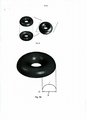
[0006] Imagens de anel se movendo exibindo um anel aparentemente se movendo com um ângulo de mudança de visão (efeito "anel rolando") são produzidas ao expor uma camada de revestimento molhada compreendendo partículas magnetizáveis ou magnéticas refletivas não isotropicamente ao campo magnético de um ímã dipolo. WO 2011/092502 divulga imagens de anéis se movendo que podem ser obtidas ou produzidas ao usar um dispositivo para orientar partículas em uma camada de revestimento. O dispositivo divulgado permite a orientação de partículas magnéticas ou magnetizáveis com a ajuda de um campo magnético produzido pela combinação de um uma folha suave magnetizável e um ímã esférico tendo seu eixo Norte-Sul perpendicular ao plano da camada de revestimento e disposto abaixo de dita folha suave magnetizável. Imagens de anel móveis da arte prévia são geralmente produzidas pelo alinhamento das partículas magnéticas ou magnetizáveis de acordo com o campo magnético de somente um ímã rotativo ou estático. Uma vez que as linhas de campo de apenas um ímã geralmente dobram de forma relativamente suave, ou seja, têm uma curvatura baixa, também a mudança na orientação das partículas magnéticas ou magnetizáveis é relativamente suave sobre a superfície da OEL. Adicionalmente, a intensidade do campo magnético diminui rapidamente com o aumento da distância a partir do ímã quando um único ímã é usado. Isto torna difícil obter um aspecto grandemente dinâmico e bem definido através de orientação das partículas magnéticas ou magnetizáveis, e pode resultar em efeitos de "anel rolando" que podem exibir bordas de anéis borradas. Este problema aumenta com o aumento de tamanho (diâmetro) da imagem de "anel rolando" quando somente um ímã rotativo ou estático é usado.[0006] Moving ring images showing an apparently moving ring at a shifting angle of view ("rolling ring" effect) are produced by exposing a wet coating layer comprising non-isotropically reflective magnetizable or magnetic particles to the magnetic field of a dipole magnet. WO 2011/092502 discloses images of moving rings that can be obtained or produced by using a device to orient particles in a coating layer. The disclosed device allows the orientation of magnetic or magnetizable particles with the help of a magnetic field produced by the combination of a soft magnetizable sheet and a spherical magnet having its North-South axis perpendicular to the plane of the coating layer and disposed below said sheet magnetizable smooth. Prior art moving ring images are generally produced by aligning magnetic or magnetizable particles according to the magnetic field of only a rotating or static magnet. Since the field lines of just one magnet generally bend relatively smoothly, ie have a low curvature, also the change in orientation of the magnetic or magnetizable particles is relatively smooth on the surface of the OEL. Additionally, the magnetic field strength rapidly decreases with increasing distance from the magnet when a single magnet is used. This makes it difficult to obtain a highly dynamic and well-defined aspect through magnetic or magnetizable particle orientation, and can result in "ring rolling" effects that can exhibit blurry ring edges. This problem increases with the increase in size (diameter) of the "rolling ring" image when only a rotating or static magnet is used.
[0007] Portanto, permanece uma necessidade de recursos de segurança, exibindo um efeito de formato em loop dinâmico visualmente atrativo cobrindo uma área estendida sobre um documento em boa qualidade, que pode ser facilmente verificado independentemente da orientação do documento de segurança, que é difícil produzir em escala de massa com o equipamento disponível para um falsário, e que podem ser providos em grande número de possíveis formatos e maneiras.[0007] Therefore, there remains a need for security features, exhibiting a visually attractive dynamic loop format effect covering an extended area over a document in good quality, which can be easily verified regardless of the orientation of the security document, which is difficult produce on a mass scale with the equipment available to a counterfeiter, and which can be provided in a large number of possible shapes and forms.
[0008] Consequentemente, é um objetivo da presente invenção superar as deficiências do estado da técnica, como discutido acima. Isto é atingido através do fornecimento de uma camada de efeito óptico, por exemplo, sobre um documento ou outro item, que apresenta um movimento aparente de dependente de ângulo de visão dos recursos de imagem sobre um comprimento estendido, tem boa nitidez e/ou contraste, e que pode ser facilmente detectado. A presente invenção provê tais camadas de efeito óptico como um recurso de segurança oculto fácil de detectar aprimorado, ou, em adição ou, de maneira alternativa, como um recurso de segurança oculto, por exemplo, no campo de segurança de documentos.[0008] Consequently, it is an object of the present invention to overcome the deficiencies of the prior art, as discussed above. This is achieved by providing an optical effect layer, for example, over a document or other item, which exhibits an apparent angle-of-view dependent movement of the image resources over an extended length, has good sharpness and/or contrast , and that it can be easily detected. The present invention provides such optical effect layers as an enhanced easy-to-detect hidden security feature, or, in addition or alternatively, as a hidden security feature, for example, in the field of document security.
[0009] São divulgadas e reivindicadas neste documento camadas de efeito óptico (OELs) compreendendo um elemento de segurança e documentos de segurança compreendendo ditas camadas de efeito óptico. Especificamente, uma camada de efeito óptico (OEL) é provida, compreendendo uma pluralidade de partículas magnéticas ou magnetizáveis não esféricas, que estão dispersas em uma composição de revestimento compreendendo um material ligante, em que pelo menos em uma área em formato de loop da OEL, pelo menos uma parte da pluralidade de partículas magnéticas ou magnetizáveis não esféricas são orientadas de maneira que seu eixo mais longo é substancialmente paralelo ao plano da OEL, dita área em formato de loop formando uma impressão óptica de um corpo em formato de loop circundando uma área central, em que, em uma seção transversal perpendicular à OEL e estendendo-se desde o centro da área central, o eixo mais longo das partículas orientadas presentes na área em formato de loop segue uma tangente de uma parte negativamente curvada ou parte positivamente curvada de uma elipse ou círculo hipotético. Pela orientação das partículas magnéticas ou magnetizáveis não esféricas desta forma, o efeito óptico de um corpo em forma de loop é gerado para um espectador.[0009] Disclosed and claimed in this document are optical effect layers (OELs) comprising a security element and security documents comprising said optical effect layers. Specifically, an optical effect layer (OEL) is provided, comprising a plurality of non-spherical magnetic or magnetizable particles, which are dispersed in a coating composition comprising a binder material, wherein at least one loop-shaped area of the OEL , at least a part of the plurality of non-spherical magnetic or magnetizable particles are oriented such that their longest axis is substantially parallel to the plane of the OEL, said loop-shaped area forming an optical impression of a loop-shaped body surrounding a central area, in which, in a cross section perpendicular to the OEL and extending from the center of the central area, the longest axis of the oriented particles present in the loop-shaped area follows a tangent of a negatively curved part or a positively curved part of an ellipse or hypothetical circle. By orienting the non-spherical magnetic or magnetizable particles in this way, the optical effect of a loop-shaped body is generated for a viewer.
[0010] Também descrito e reivindicado nele são dispositivos geradores de campo magnéticos que podem ser usados para produzir as camadas de efeito óptico descritas neste documento. Especificamente, um dispositivo geradores de campo magnético para a formação de uma camada de efeito óptico é provido, dito dispositivo sendo configurado para o recebimento de uma composição de revestimento compreendendo uma pluralidade de partículas magnéticas ou magnetizáveis não esféricas e um material ligante, e compreendendo um ou mais imãs configurados para orientar pelo menos uma parte da pluralidade de partículas magnéticas ou magnetizáveis não esféricas em paralelo ao plano da camada de efeito óptico em pelo menos uma área em formato de loop respectiva, a dita área em formato de loop formando a impressão óptica de um corpo em formato de loop fechado circundando uma área central, em que, em uma seção transversal perpendicular à OEL e estendendo-se desde o centro da área central, o eixo mais longo das partículas orientadas presentes na área em formato de loop formando a impressão do corpo em formato de loop segue uma tangente de uma parte negativamente curvada ou positivamente curvada parte de uma elipse ou círculo hipotético. A composição de revestimento pode ser aplicada diretamente a uma superfície de apoio que é parte do dispositivo e formada por um membro sólido (tal como uma placa) ou a um substrato provido em tal uma superfície de apoio, ou alternativamente, o substrato pode assumir o papel de uma superfície de apoio para a composição do revestimento.[0010] Also described and claimed therein are magnetic field generating devices that can be used to produce the optical effect layers described in this document. Specifically, a magnetic field generating device for forming an optical effect layer is provided, said device being configured for receiving a coating composition comprising a plurality of non-spherical magnetic or magnetizable particles and a binding material, and comprising a or more magnets configured to orient at least a portion of the plurality of non-spherical magnetic or magnetizable particles parallel to the plane of the optical effect layer in at least one respective loop-shaped area, said loop-shaped area forming the optical imprint of a closed-loop-shaped body surrounding a central area, where, in a cross section perpendicular to the OEL and extending from the center of the central area, the longest axis of the oriented particles present in the loop-shaped area forming the loop-shaped body print follows a tangent of a negatively curved part or positively c curved part of a hypothetical ellipse or circle. The coating composition can be applied directly to a support surface that is part of the device and formed by a solid member (such as a plate) or to a substrate provided on such a support surface, or alternatively, the substrate can assume the role of a support surface for coating composition.
[0011] Também descrito e reivindicado neste documento são processos para produzir o elemento de segurança, as camadas de efeito óptico compreendendo-a e usos das camadas efeito óptico para a proteção contra contrafacção de um documento de segurança ou para uma aplicação decorativa nas artes gráficas. Especificamente, a presente invenção se refere a um processo para produzir uma camada de efeito óptico (OEL), compreendendo as etapas de:a) aplicação, em uma superfície de substrato ou em uma superfície de apoio de um dispositivo gerador de campo magnético, de uma composição de revestimento compreendendo um ligante e uma pluralidade de partículas magnetizáveis ou magnéticas não esféricas, a dita composição de revestimento estando em um primeiro estado (fluido),b) exposição da composição de revestimento em um primeiro estado ao campo magnético de um dispositivo gerador de campo magnético, preferencialmente um como definido em qualquer uma das reivindicações 8-12, desse modo orientando pelo menos uma parte das partículas magnetizáveis ou magnéticas não esféricas em pelo menos uma área em formato de loop circundando uma área central de tal modo que, em uma seção transversal perpendicular à OEL e estendendo-se desde o centro da área central, o eixo mais longo das partículas presentes na área em formato de loop segue uma tangente de tanto uma parte curvada negativamente ou uma curvada positivamente de um círculo ou elipse hipotético, ec) endurecimento da composição de revestimento a um segundo estado de modo a fixar as partículas magnetizáveis ou magnéticas não esféricas em suas posições e orientações adotadas.[0011] Also described and claimed in this document are processes for producing the security element, the optical effect layers comprising it, and uses of the optical effect layers for counterfeiting protection of a security document or for a decorative application in the graphic arts . Specifically, the present invention relates to a process for producing an optical effect layer (OEL), comprising the steps of: a) applying, on a substrate surface or on a supporting surface of a magnetic field generating device, of a coating composition comprising a binder and a plurality of magnetizable or non-spherical magnetic particles, said coating composition being in a first state (fluid), b) exposing the coating composition in a first state to the magnetic field of a generating device of a magnetic field, preferably one as defined in any one of claims 8-12, thereby orienting at least a portion of the non-spherical magnetizable or magnetic particles in at least a loop-shaped area surrounding a central area such that, in a cross section perpendicular to the OEL and extending from the center of the central area, the longest axis of particles present in the area. and the loop-shaped one follows a tangent of either a negatively curved or a positively curved part of a hypothetical circle or ellipse, and c) hardening the coating composition to a second state in order to fix the non-spherical magnetizable or magnetic particles in their positions and adopted guidelines.
[0012] Modalidades adicionais preferenciais e aspectos da presente invenção vão se tornar aparentes, tendo em conta as reivindicações dependentes e a seguinte descrição.Vários aspectos da presente invenção podem ser resumidos como segue:[0012] Additional preferred embodiments and aspects of the present invention will become apparent in light of the dependent claims and the following description. Various aspects of the present invention may be summarized as follows:
1. Uma camada de efeito óptico (OEL) compreendendo uma pluralidade de partículas magnéticas ou magnetizáveis não esféricas, que são dispersas em uma composição de revestimento compreendendo um material ligante, em que em pelo menos uma área em formato de loop da OEL, pelo menos uma parte da pluralidade de partículas magnéticas ou magnetizáveis não esféricas são orientadas de maneira que seu eixo mais longo é substancialmente paralelo ao plano da OEL, dita área em formato de loop formando a impressão óptica de um corpo fechado em formato de loop circundando uma área central, em que, em uma seção transversal perpendicular à OEL e estendendo-se desde o centro da área central, o eixo mais longo das partículas orientadas presentes na área em formato de loop formando a impressão do corpo em formato de loop segue uma tangente de uma parte negativamente curvada ou parte positivamente curvada de uma elipse ou círculo hipotético.1. An optical effect layer (OEL) comprising a plurality of non-spherical magnetic or magnetizable particles, which are dispersed in a coating composition comprising a binder material, wherein in at least one loop-shaped area of the OEL, at least a part of the plurality of non-spherical magnetic or magnetizable particles are oriented such that their longest axis is substantially parallel to the plane of the OEL, said loop-shaped area forming the optical impression of a closed loop-shaped body surrounding a central area , in which, in a cross section perpendicular to the OEL and extending from the center of the central area, the longest axis of the oriented particles present in the loop-shaped area forming the loop-shaped body print follows a tangent of a negatively curved or positively curved part of an ellipse or hypothetical circle.
2. A camada de efeito óptico (OEL), de acordo com o item 1, em que a OEL adicionalmente compreende uma área externa fora da área em forma de loop fechada, e a área externa ao redor da área em forma de loop compreende uma pluralidade de partículas magnéticas ou magnetizáveis não-esféricas, em que pelo menos uma parte da pluralidade de partículas magnéticas ou magnetizáveis não esféricas dentro da área externa são orientadas tal que seu eixo mais longo seja substancialmente perpendicular ao plano da OEL ou orientado aleatoriamente.2. The optical effect layer (OEL) according to item 1, wherein the OEL additionally comprises an outer area outside the closed loop-shaped area, and the outer area around the loop-shaped area comprises a A plurality of non-spherical magnetic or magnetizable particles, wherein at least a portion of the plurality of non-spherical magnetic or magnetizable particles within the outer area are oriented such that their longest axis is substantially perpendicular to the plane of the OEL or randomly oriented.
3. A camada de efeito óptico (OEL), de acordo com o item 1 ou 2, caracterizada pelo fato de que a área central circundada pela área em formato de loop mais interna compreende uma pluralidade de partículas magnéticas ou magnetizáveis não esféricas, em que uma parte da pluralidade das partículas magnéticas ou magnetizáveis não esféricas dentro da área central são orientadas tal que seu eixo mais longo é substancialmente paralelo ao plano da OEL, formando o efeito óptico de uma saliência dentro da área central do corpo em formato de loop.3. The optical effect layer (OEL), according to item 1 or 2, characterized in that the central area surrounded by the innermost loop-shaped area comprises a plurality of non-spherical magnetic or magnetizable particles, in which a portion of the plurality of non-spherical magnetic or magnetizable particles within the central area are oriented such that their longest axis is substantially parallel to the plane of the OEL, forming the optical effect of a protrusion within the central area of the loop-shaped body.
4. A camada de efeito óptico (OEL), de acordo com o item 3, em que uma parte do formato periférico externo da saliência é semelhante ao formato do corpo em formato de loop.4. The optical effect layer (OEL) according to item 3, in which a part of the outer peripheral shape of the boss is similar to the shape of the body in loop shape.
5. A camada de efeito óptico (OEL), de acordo com o item 4, em que o corpo em formato de loop tem a forma de um anel e a saliência tem o formato de uma meia-esfera ou um círculo sólido.5. The optical effect layer (OEL) according to item 4, wherein the loop-shaped body is in the shape of a ring and the protrusion is in the shape of a half-sphere or a solid circle.
6. A camada de efeito óptico (OEL), de acordo com qualquer um dos itens anteriores 1,2, 3, 4 e 5, em que pelo menos uma parte da pluralidade de partículas magnéticas ou magnetizáveis não esféricas é constituída por compreende pigmentos magnéticos ou magnetizáveis variáveis opticamente não esféricos.6. The optical effect layer (OEL) according to any of the preceding
7. A camada de efeito óptico (OEL), de acordo com o item 6, em que os pigmentos magnéticos ou magnetizáveis variáveis opticamente não esféricos são selecionados a partir do grupo consistindo em pigmentos de interferência de película fina magnética, pigmentos de cristal líquido colestérico magnéticos e suas misturas.7. The optical effect layer (OEL) according to item 6, wherein non-spherical optically variable magnetic or magnetizable pigments are selected from the group consisting of magnetic thin-film interference pigments, cholesteric liquid crystal pigments magnetics and their mixtures.
8. Um dispositivo gerador de campo magnético para a formação de uma camada de efeito óptico, o dito dispositivo sendo configurado para o recebimento de uma composição de revestimento compreendendo uma pluralidade de partículas magnéticas ou magnetizáveis não esféricas e um material ligante, e compreendendo um ou mais imãs configurados para orientar pelo menos uma parte da pluralidade de partículas magnéticas ou magnetizáveis não esféricas paralela ao plano da camada de efeito óptico em pelo menos uma área em formato de loop respectiva, a dita área em formato de loop formando a impressão ótica de um corpo em formato de loop fechado circundando uma área central, em que, em uma seção transversal perpendicular à OEL e estendendo-se desde o centro da área central, o eixo mais longo das partículas orientadas presentes na área em formato de loop formando a impressão do corpo em formato de loop segue uma tangente de uma parte negativamente curvada ou positivamente curvada parte de uma elipse ou círculo hipotético.8. A magnetic field generating device for forming an optical effect layer, said device being configured for receiving a coating composition comprising a plurality of non-spherical magnetic or magnetizable particles and a binding material, and comprising one or plus magnets configured to orient at least a portion of the plurality of non-spherical magnetic or magnetizable particles parallel to the plane of the optical effect layer in at least a respective loop-shaped area, said loop-shaped area forming the optical impression of a closed-loop-shaped body surrounding a central area, in which, in a cross section perpendicular to the OEL and extending from the center of the central area, the longest axis of the oriented particles present in the loop-shaped area forming the impression of the loop-shaped body follows a tangent of a negatively curved part or a positively curved part of an ellipse o u hypothetical circle.
9. O dispositivo gerador de campo magnético, de acordo com o item 8, quea) compreende uma superfície de apoio para receber a composição de revestimento, e a superfície de apoio é formada pora1) um prato no qual a composição de revestimento pode ser aplicada diretamente,a2) um prato para o recebimento de um substrato no qual a composição de revestimento pode ser aplicada, oua3) uma superfície de um imã, na qual a composição de revestimento pode ser aplicada diretamente, ou acima, ou na qual um substrato no qual a composição de revestimento pode ser aplicada pode ser provido; ou b) está configurado para receber um substrato no qual a camada de efeito óptico é provida, o dito substrato substituindo a superfície de apoio.9. The magnetic field generating device according to item 8, which a) comprises a bearing surface for receiving the coating composition, and the bearing surface is formed by a1) a plate on which the coating composition can be applied directly, a2) a plate for receiving a substrate on which the coating composition can be applied, or a3) a surface of a magnet, on which the coating composition can be applied directly, or above, or on which a substrate does not which coating composition can be applied can be provided; or b) is configured to receive a substrate on which the optical effect layer is provided, said substrate replacing the supporting surface.
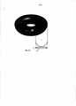
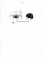
10. O dispositivo gerador de campo magnético, de acordo com o item 9, o dito dispositivo compreendendo uma superfície de apoio ou sendo configurado para receber um substrato substituindo a superfície de apoio, o dispositivo compreendendo, adicionalmente,a) um ímã dipolo em barra disposto abaixo da superfície de apoio ou o substrato substituindo a superfície de apoio e tendo seu eixo Norte- Sul perpendicular à superfície de apoio/superfície de substrato e uma peça de polo, na quala1) a peça de polo é disposta abaixo do ímã dipolo em barra e em contato com um dos polos do ímã, e/oua2) na qual a peça de polo é espaçada além de e lateralmente envolve o ímã dipolo em barra;b) um ou mais pares de ímãs de dipolo em barra abaixo da superfície de apoio e rotativo em torno de um eixo de rotação que é substancialmente perpendicular à superfície de apoio, os ditos ímãs tendo seu eixo Norte-Sul substancialmente paralelo à superfície de apoio e o seu eixo Norte-Sul magnético substancialmente radial em relação ao eixo de rotação eb1) direções Norte-Sul magnéticas opostas, oub2) a mesma direção Norte-Sul magnéticao um ou mais pares, sendo cada um formado por dois ímãs dipolos em barra que se localizam substancialmente simetricamente sobre o eixo de rotação;c) um ou mais pares de ímãs dipolos em barra abaixo da superfície de apoio e rotativo em torno de um eixo de rotação que é substancialmente perpendicular à superfície de apoio, os ditos ímãs tendo i) seu eixo Norte-Sul substancialmente perpendicular à superfície de apoio, ii) seu eixo Norte-Sul magnético substancialmente paralelo ao eixo de rotação e iii) direções Norte- Sul magnéticas opostas, o um ou mais pares, cada um consistindo em conjuntos de dois ímãs dipolos em barra sendo simetricamente dispostos sobre o eixo de rotação;d) três ímãs dipolos em barra abaixo da superfície de apoio e providos rotativos em torno de um eixo de rotação que é substancialmente perpendicular à superfície de apoio, em que dois dos três ímãs dipolos em barra estão localizados em lados opostos e sobre o eixo de rotação, e o terceiro ímã dipolo em barra é posicionado no eixo de rotação e no qual i) cada um dos ímãs tem seu eixo Norte-Sul substancialmente paralelo à superfície de apoio, ii) os dois ímãs espaçados para além do eixo de rotação têm o seu eixo Norte-Sul substancialmente radial em relação ao eixo de rotação, iii) os dois ímãs dipolos em barra espaçados para além do eixo de rotação têm as mesmas direções Norte-Sul, isto é, assimétricas em relação ao eixo de rotação e iv) o terceiro ímã dipolo em barra no eixo de rotação tem uma direção Norte-Sul oposta à direção Norte-Sul dos dois ímãs dipolos em barra espaçados;e) um ímã dipolo abaixo da superfície de apoio ou o substrato substituindo a superfície de apoio, o ímã dipolo consistindo em um corpo em formato de loop, o dito ímã tendo seu eixo Norte-Sul magnético, estendendo-se radialmente desde o centro do corpo em formato de loop até a periferia;f) um ou mais ímãs dipolos em barra abaixo da superfície de apoio ou o substrato substituindo a superfície de apoio e rotativo sobre um eixo de rotação que é substancialmente perpendicular à superfície de apoio/à superfície de substrato, cada um do um ou mais ímãs dipolos em barra tendo seu eixo Norte-Sul magnético substancialmente paralelo à superfície de apoio/superfície de substrato tendo seu eixo Norte-Sul magnético substancialmente radial em relação ao eixo de rotação e as direções Norte-Sul do dito um ou mais ímãs dipolos em barra apontando todo em direção ou muito longe do eixo de rotação; oug) três ou mais ímãs dipolos em barra abaixo da superfície de apoio, todos os três ou mais ímãs sendo localizados de maneira estática sobre um centro de simetria, cada um dos três ou mais ímãs dipolos em barra tendo i) seu eixo Norte-Sul magnético substancialmente paralelo à superfície de apoio, ii) seu eixo Norte-Sul magnético alinhado tal como para ser substancialmente radialmente estendido desde o centro da simetria e iii) as direções Norte-Sul do dito um ou mais imãs apontando todos no sentido ou todos longe do centro de simetria.10. The magnetic field generating device according to item 9, said device comprising a support surface or being configured to receive a substrate replacing the support surface, the device further comprising a) a bar dipole magnet disposed below the support surface or the substrate replacing the support surface and having its North-South axis perpendicular to the support surface/substrate surface and a pole piece, in which a1) the pole piece is disposed below the dipole magnet at bar and in contact with one of the poles of the magnet, and/or a2) in which the pole piece is spaced beyond and laterally surrounds the bar dipole magnet; b) one or more pairs of bar dipole magnets below the surface of bearing and rotatable about an axis of rotation which is substantially perpendicular to the bearing surface, said magnets having their North-South axis substantially parallel to the bearing surface and their North-South magnetic axis substantially radial with respect to the axis of rotation and b1) opposite magnetic North-South directions, or b2) the same magnetic North-South direction one or more pairs, each being formed by two bar-dipole magnets which are located substantially symmetrically about the axis of rotation; c) one or more pairs of bar dipole magnets below the bearing surface and rotating about an axis of rotation which is substantially perpendicular to the bearing surface, said magnets having i) their North-South axis substantially perpendicular to the surface of support, ii) its magnetic North-South axis substantially parallel to the axis of rotation and iii) opposing magnetic North-South directions, the one or more pairs, each consisting of sets of two bar dipole magnets being symmetrically disposed about the axis of rotation; d) three bar dipole magnets below the bearing surface and provided rotatable about an axis of rotation which is substantially perpendicular to the bearing surface, wherein two of the three dipole magnets the bar ones are located on opposite sides and about the axis of rotation, and the third bar dipole magnet is positioned on the axis of rotation and in which i) each of the magnets has its North-South axis substantially parallel to the bearing surface, ii) the two magnets spaced beyond the axis of rotation have their North-South axis substantially radial to the axis of rotation, iii) the two bar dipole magnets spaced beyond the axis of rotation have the same North-South directions , that is, asymmetric with respect to the axis of rotation and iv) the third bar dipole magnet on the axis of rotation has a North-South direction opposite the North-South direction of the two spaced apart bar dipole magnets; e) a dipole magnet below of the supporting surface or the substrate replacing the supporting surface, the dipole magnet consisting of a loop-shaped body, said magnet having its magnetic North-South axis, extending radially from the center of the loop-shaped body to the periphery; f) one or more dipole magnets below the bearing surface or the substrate replacing the bearing surface and rotating about an axis of rotation that is substantially perpendicular to the bearing surface/substrate surface, each of the one or more bar dipole magnets having its North axis -South magnetic substantially parallel to the support surface/substrate surface having its magnetic North-South axis substantially radial to the axis of rotation and the North-South directions of said one or more bar dipole magnets pointing all towards or very far away of the axis of rotation; or g) three or more bar dipole magnets below the supporting surface, all three or more magnets being statically located over a center of symmetry, each of the three or more bar dipole magnets having i) its North-South axis magnetic substantially parallel to the bearing surface, ii) its North-South magnetic axis aligned such as to be substantially radially extended from the center of symmetry and iii) the North-South directions of said one or more magnets pointing all towards or all away from the center of symmetry.
11. O dispositivo gerador de campo magnético para a formação de uma camada de efeito óptico de acordo com o item 10, modalidades b2, c), ou d) em que, mediante rotação dos ímãs em torno do eixo de rotação, linhas de campo magnético dependente do tempo que são substancialmente paralelas à superfície de apoio são geradas em uma área definindo uma em formato de loop e dentro de uma área central circundada pelo formato de loop e sendo espaçados além do formato de loop.11. The magnetic field generating device for the formation of an optical effect layer according to item 10, modes b2, c), or d) in which, upon rotation of the magnets around the axis of rotation, field lines Time-dependent magnetics that are substantially parallel to the support surface are generated in an area defining a loop shape and within a central area surrounded by the loop shape and being spaced beyond the loop shape.
12. O dispositivo gerador de campo magnético, de acordo com o item 12, no qual o corpo em formato de loop assume a forma de um anel e a área central circundada pelo corpo em formato de loop assume a forma de um círculo sólido ou meia-esfera.12. The magnetic field generating device according to item 12, in which the loop-shaped body takes the form of a ring and the central area surrounded by the loop-shaped body takes the form of a solid circle or half -ball.
13. Um conjunto de impressão compreendendo os dispositivos geradores de campo magnético recitados em qualquer um dos itens 8-12.13. A printing set comprising the magnetic field generating devices recited in any one of items 8-12.
14. Utilização dos dispositivos geradores de campo magnético recitados no item 8-12 para produzir a OEL recitada em qualquer um dos itens 1-7.14. Use of the magnetic field generating devices recited in item 8-12 to produce the OEL recited in any of items 1-7.
15. Um processo para produzir uma camada de efeito óptico (OEL), compreendendo as etapas de:a) aplicação, em uma superfície de substrato ou em uma superfície de apoio de um dispositivo gerador de campo magnético, de uma composição de revestimento compreendendo um ligante e uma pluralidade de partículas magnetizáveis ou magnéticas não esféricas, a dita composição de revestimento estando em um primeiro estado,b) exposição da composição de revestimento em um primeiro estado ao campo magnético de um dispositivo gerador de campo magnético, preferencialmente um como definido em qualquer um dos itens 8-12, desse modo orientando pelo menos uma parte das partículas magnetizáveis ou magnéticas não esféricas em pelo menos uma área em formato de loop circundando uma área central de tal modo que, em uma seção transversal perpendicular à OEL e estendendo-se desde o centro da área central, o eixo mais longo das partículas presentes na área em formato de loop segue uma tangente de tanto uma parte curvada negativamente ou uma curvada positivamente de um círculo hipotético, ec) enrijecimento da composição de revestimento a um segundo estado de modo a fixar as partículas magnetizáveis ou magnéticas não esféricas em suas posições e orientações adotadas.15. A process for producing an optical effect layer (OEL), comprising the steps of: a) applying, to a substrate surface or a support surface of a magnetic field generating device, a coating composition comprising a binder and a plurality of magnetizable or non-spherical magnetic particles, said coating composition being in a first state, b) exposing the coating composition in a first state to the magnetic field of a magnetic field generating device, preferably one as defined in any of items 8-12, thereby orienting at least a portion of the magnetizable or non-spherical magnetic particles in at least a loop-shaped area surrounding a central area such that, in a cross section perpendicular to the OEL and extending it if from the center of the central area, the longest axis of the particles present in the loop-shaped area follows a tangent of both a curved part. negatively curved or positively curved from a hypothetical circle, and c) stiffening the coating composition to a second state so as to fix the magnetizable or non-spherical magnetic particles in their adopted positions and orientations.
16. O processo de acordo com o item 15, onde a etapa de endurecimento c) é feita pela cura por radiação de luz UV-Vis.16. The process according to item 15, where the hardening step c) is done by curing by UV-Vis light radiation.
17. Uma camada de efeito óptico de acordo com qualquer um dos itens 1 a 7, a qual é obtida pelo processo de item 15 ou item 16.17. An optical effect layer according to any one of items 1 to 7, which is obtained by the process of item 15 or item 16.
18. Um substrato revestido de efeito óptico (OEC) compreendendo uma ou mais camadas de efeito óptico de acordo com qualquer um dos itens 1 a 7 ou 17 em um substrato.18. An optical effect coated (OEC) substrate comprising one or more optical effect layers according to any one of items 1 to 7 or 17 on a substrate.
19. Um documento de segurança, preferencialmente uma cédula ou um documento de identidade, compreendendo uma camada de efeito óptico recitado em qualquer um dos itens 1 a 7 ou 17.19. A security document, preferably a banknote or an identity document, comprising an optical effect layer recited in any one of items 1 to 7 or 17.
20. Utilização da camada de efeito óptico recitada em qualquer um dos itens 1 a 7 ou 18 ou do substrato revestido de efeito óptico recitado no item 18 para a proteção de um documento de segurança contra contrafacção ou fraude ou para uma aplicação decorativa.20. Use of the optical effect layer recited in any one of items 1 to 7 or 18 or the optical effect coated substrate recited in item 18 for the protection of a security document against counterfeiting or fraud or for a decorative application.
[001] A camada de efeito óptico (OEL) de acordo com a presente invenção e sua produção são agora descritas em mais detalhes, tendo como referência as figuras e a modalidades particulares, em queFig. 1 ilustra esquematicamente um corpo toroidal (Fig. 1A) e a variação da orientação de partículas magnéticas ou magnetizáveis não esféricas seguindo uma tangente a uma curva negativa (Fig. 1B) ou uma curva positiva (Fig. 1) de uma elipse hipotética em uma seção transversal estendendo-se desde o centro de uma área central circundada por uma área em formato de loop formando o efeito óptico de um corpo em formato de loop, em relação à superfície do substrato (não mostrada, abaixo da camada L na figura) na qual a OEL (L) é provida. Nas figuras 1B e 1C, a orientação do eixo mais longo das partículas segue uma tangente de uma parte negativamente curvada ou positivamente curvada de uma elipse hipotética na seção transversal. As Figuras 1B e 1C ilustram, assim, a orientação das partículas, em uma seção transversal perpendicular ao plano da OEL e estendendo-se desde o centro da área central de uma parte da área em formato de loop provendo o efeito óptico de um corpo em formato de loop de dentro (a lateral da área central) para fora.Fig. 2 Fig. 2A mostra uma fotografia de uma OEL provendo um efeito óptico dinâmico de um corpo em formato de loop conforme provido de acordo com uma modalidade da presente invenção. Fig. 2B mostra uma fotografia de uma OEL com uma saliência de acordo com uma modalidade da presente invenção.Fig. 3 ilustra esquematicamente a estrutura de um dispositivo gerador de campo magnético para produzir uma OEL de acordo com uma primeira modalidade exemplar.Fig. 4 ilustra esquematicamente a estrutura de um dispositivo gerador de campo magnético para produzir uma OEL de acordo com uma segunda modalidade exemplar.Fig. 5 ilustra esquematicamente a estrutura de um dispositivo gerador de campo magnético para produzir uma OEL de acordo com uma terceira modalidade exemplar. Fig. 6 ilustra esquematicamente a estrutura de um dispositivo gerador de campo magnético para produzir uma OEL de acordo com uma quinta modalidade exemplar.Fig. 7 lustra esquematicamente a estrutura de um dispositivo gerador de campo magnético para produzir uma OEL de acordo com uma sexta modalidade exemplar.Fig. 8 ilustra esquematicamente a estrutura de um dispositivo gerador de campo magnético para produzir uma OEL de acordo com uma sétima modalidade exemplar.Fig. 9 ilustra esquematicamente a estrutura de dispositivos para produção de uma OEL compreendendo adicionalmente uma saliência de acordo com uma primeira modalidade exemplar.Fig. 10 ilustra esquematicamente a estrutura de dispositivos para produção de uma OEL compreendendo adicionalmente uma saliência de acordo com uma segunda modalidade exemplar.Fig. 11 ilustra esquematicamente a estrutura de dispositivos para a produção de uma OEL compreendendo adicionalmente uma saliência de acordo com uma terceira modalidade exemplar.Fig. 12 ilustra esquematicamente um substrato revestido de efeito óptico (OEC) compreendendo dois componentes (A & B) de camada de efeito óptico (OEL) separada dispostos em um substrato. Fig. 13 mostra exemplos de formatos em loop circundando uma área central,Fig. 14A ilustra esquematicamente a orientação de partículas magnéticas ou magnetizáveis não esféricas no elemento de segurança em formato de loop da presente invenção; eFig.14B ilustra esquematicamente a orientação de partículas magnéticas ou magnetizáveis não esféricas em um elemento de segurança em formato de loop da presente invenção, em que a área central circundada por um formato de loop é preenchida com uma saliência.[001] The optical effect layer (OEL) according to the present invention and its production are now described in more detail, with reference to the figures and particular modalities, in whichFig. 1 schematically illustrates a toroidal body (Fig. 1A) and the variation of orientation of non-spherical magnetic or magnetizable particles following a tangent to a negative curve (Fig. 1B) or a positive curve (Fig. 1) of a hypothetical ellipse in a cross section extending from the center of a central area surrounded by a loop-shaped area forming the optical effect of a loop-shaped body, relative to the substrate surface (not shown, below layer L in the figure) in the which OEL (L) is provided. In figures 1B and 1C, the orientation of the longest axis of the particles follows a tangent of a negatively curved or positively curved part of a hypothetical ellipse in the cross section. Figures 1B and 1C thus illustrate the orientation of the particles, in a cross section perpendicular to the plane of the OEL and extending from the center of the central area of a part of the area in a loop format providing the optical effect of a body in loop shape from the inside (the side of the center area) to the outside.Fig. Fig. 2A shows a photograph of an OEL providing a dynamic optical effect of a loop-shaped body as provided in accordance with an embodiment of the present invention. Fig. 2B shows a photograph of an OEL with a protrusion in accordance with an embodiment of the present invention. Fig. 3 schematically illustrates the structure of a magnetic field generating device for producing an OEL in accordance with a first exemplary embodiment.Fig. 4 schematically illustrates the structure of a magnetic field generating device for producing an OEL in accordance with a second exemplary embodiment.Fig. 5 schematically illustrates the structure of a magnetic field generating device for producing an OEL in accordance with a third exemplary embodiment. Fig. 6 schematically illustrates the structure of a magnetic field generating device for producing an OEL in accordance with a fifth exemplary embodiment. Fig. 7 schematically illustrates the structure of a magnetic field generating device to produce an OEL in accordance with a sixth exemplary embodiment.Fig. 8 schematically illustrates the structure of a magnetic field generating device for producing an OEL in accordance with a seventh exemplary embodiment.Fig. 9 schematically illustrates the structure of devices for producing an OEL further comprising a protrusion according to a first exemplary embodiment.Fig. 10 schematically illustrates the structure of devices for producing an OEL further comprising a protrusion according to a second exemplary embodiment.Fig. 11 schematically illustrates the structure of devices for producing an OEL further comprising a protrusion according to a third exemplary embodiment.Fig. 12 schematically illustrates a coated optical effect (OEC) substrate comprising two separate optical effect layer (OEL) components (A & B) disposed on a substrate. Fig. 13 shows examples of looped shapes surrounding a central area,Fig. 14A schematically illustrates the orientation of non-spherical magnetic or magnetizable particles in the loop-shaped security element of the present invention; eFig.14B schematically illustrates the orientation of non-spherical magnetic or magnetizable particles in a loop-shaped security element of the present invention, wherein the central area surrounded by a loop-shaped is filled with a protrusion.
[013] As seguintes definições devem ser usadas para interpretar o significado dos termos discutidos na descrição e citados nas reivindicações.[013] The following definitions shall be used to interpret the meaning of terms discussed in the description and cited in the claims.
[014] Conforme usado neste documento, o artigo indefinido "um(a)" indica que um bem como mais de um e não necessariamente limita seu substantivo de referência ao singular.[014] As used in this document, the indefinite article "a" indicates a good as more than one and does not necessarily limit its noun of reference to the singular.
[015] Conforme usado neste documento, o termo "cerca de" significa que a quantia ou valor em questão pode ser o valor específico designado ou algum outro valor em suas proximidades. Geralmente, o termo "cerca de" denotando um certo valor destina-se a denotar um intervalo dentro de ± 5% do valor. Como um exemplo, a frase "cerca de 100" denota um intervalo de 100 + 5, ou seja, o intervalo de 95 a 105. Geralmente, quando o termo "cerca de" é usado, pode esperar-se que resultados ou efeitos semelhantes de acordo com a invenção podem ser obtidos dentro de um intervalo de ± 5% do valor indicado.[015] As used herein, the term "about" means that the amount or amount in question may be the specific designated amount or some other amount in its vicinity. Generally, the term "about" denoting a certain value is intended to denote a range within ±5% of the value. As an example, the phrase "about 100" denotes a range of 100 + 5, that is, the range from 95 to 105. Generally, when the term "about" is used, similar results or effects can be expected. according to the invention can be obtained within a range of ± 5% of the indicated value.
[016] Conforme usado neste documento, o termo "e/ou" significa que ou todos ou apenas um dos elementos do dito grupo pode estar presente. Por exemplo, entende-se "A e/ou B" como "somente A, ou somente B ou ambos A e B". No caso de "somente A", o termo também abrange a possibilidade de que B está ausente, ou seja, "somente A, mas não B".[016] As used in this document, the term "and/or" means that either all or only one of the elements of said group may be present. For example, "A and/or B" is understood to mean "only A, or only B, or both A and B". In the case of "only A", the term also encompasses the possibility that B is absent, ie "only A but not B".
[017] O termo "substancialmente paralelo" refere-se a desvio de menos de 20° do alinhamento paralelo e o termo "substancialmente perpendicular" refere-se a desvio de menos de 20° do alinhamento perpendicular. Preferencialmente, o termo "substancialmente paralelo" refere-se ao desvio de não mais de 10° do alinhamento paralelo e o termo "substancialmente perpendicular" refere-se ao desvio de não mais de 10° do alinhamento perpendicular.[017] The term "substantially parallel" refers to deviation of less than 20° from parallel alignment and the term "substantially perpendicular" refers to deviation of less than 20° from perpendicular alignment. Preferably, the term "substantially parallel" refers to deviation of not more than 10° from parallel alignment and the term "substantially perpendicular" refers to deviation of not more than 10° from perpendicular alignment.
[018] O termo "pelo menos parcialmente" destina-se a denotar que a seguinte propriedade é cumprida em certa medida ou completamente. Preferencialmente, o termo denota que a seguinte propriedade é cumprida pelo menos 50% ou mais, mais preferencialmente pelo menos 75%, ainda mais preferencialmente pelo menos 90%. Pode ser preferencial que o termo denote "completamente".[018] The term "at least partially" is intended to denote that the following property is fulfilled to some extent or completely. Preferably, the term denotes that the following property is fulfilled at least 50% or more, more preferably at least 75%, even more preferably at least 90%. It may be preferred that the term denote "completely".
[019] Os termos "substancialmente" e "essencialmente" são usados para denotar que o seguinte recurso, propriedade ou parâmetro é completamente (totalmente) realizado ou satisfeito ou para um grau maior que afeta negativamente o resultado pretendido. Assim, dependendo das circunstâncias, o termo "substancialmente" ou "essencialmente" significa, preferencialmente, por exemplo, pelo menos 80%, pelo menos 90%, pelo menos 95% ou 100%.[019] The terms "substantially" and "essentially" are used to denote that the following feature, property, or parameter is either completely (totally) realized or satisfied or to a greater degree that negatively affects the intended outcome. Thus, depending on the circumstances, the term "substantially" or "essentially" preferably means, for example, at least 80%, at least 90%, at least 95% or 100%.
[020] O termo "compreendendo" conforme usado neste documento destina-se a ser não exclusivo e em aberto. Assim, por exemplo uma composição de revestimento compreendendo um composto A pode incluir outros compostos além de A. No entanto, o termo "compreendendo" abrange também os significados mais restritivos de "consistindo essencialmente em" e "consistindo em", de modo que, por exemplo, "uma composição de revestimento compreendendo um composto A" também pode consistir (essencialmente) do composto A.[020] The term "comprising" as used in this document is intended to be non-exclusive and open ended. Thus, for example a coating composition comprising a compound A may include compounds other than A. However, the term "comprising" also encompasses the more restrictive meanings of "consisting essentially of" and "consisting of", so that, for example, "a coating composition comprising a compound A" may also (essentially) consist of compound A.
[021] O termo "composição de revestimento" refere-se a qualquer composição que é capaz de formar uma camada de efeito óptico (OEL) da presente invenção em um substrato sólido e que pode ser aplicada preferencialmente, mas não exclusivamente por um método de impressão. A composição de revestimento compreende pelo menos uma pluralidade de partículas magnéticas ou magnetizáveis não esféricas e um ligante. Devido a seu formato não esférico, as partículas têm refletividade não isotrópica.[021] The term "coating composition" refers to any composition that is capable of forming an optical effect layer (OEL) of the present invention on a solid substrate and that can be applied preferentially, but not exclusively by a method of print. The coating composition comprises at least a plurality of non-spherical magnetic or magnetizable particles and a binder. Due to their non-spherical shape, the particles have non-isotropic reflectivity.
[022] O termo "camada de efeito óptico (OEL)" conforme usado neste documento denota uma camada que compreende pelo menos uma pluralidade de partículas magnéticas ou magnetizáveis não esféricas orientadas e um ligante, em que a orientação das partículas magnéticas ou magnetizáveis não esféricas é fixa dentro do ligante.[022] The term "optical effect layer (OEL)" as used herein denotes a layer comprising at least a plurality of oriented non-spherical magnetic or magnetizable particles and a binder, wherein the orientation of the non-spherical magnetic or magnetizable particles is fixed inside the binder.
[023] Conforme usado neste documento, o termo "substrato revestido de efeito óptico (OEC)" é usado para denotar o produto resultante da provisão da OEL em um substrato. A OEC pode consistir do substrato e da OEL, mas também pode compreender outros materiais e/ou camadas que não sejam a OEL. O termo OEC também abrange, assim, documentos de segurança, tais como cédulas.[023] As used in this document, the term "coated optical effect substrate (OEC)" is used to denote the product resulting from the provision of OEL on a substrate. The OEC may consist of the substrate and the OEL, but may also comprise materials and/or layers other than the OEL. The term OEC thus also encompasses security documents such as banknotes.
[024] O termo "área em formato de loop" denota uma área dentro da OEL que se recombina e provê o efeito óptico ou impressão óptica de um corpo em formato de loop. A área assume a forma de um loop fechado circundando uma área central. O "formato de loop” pode ter um formato redondo, oval, elipsoide, quadrado, triangular, retangular ou qualquer formato poligonal. Exemplos de formatos em loop incluem um círculo, um retângulo ou quadrado (preferencialmente com cantos arredondados), um triângulo, um pentágono, um hexágono, um heptágono, um octógono, etc. Preferencial mente, a área formando um loop não se cruza. O termo "corpo em formato de loop" é usado para denotar o efeito óptico que é obtido pela orientação de partículas magnéticas ou magnetizáveis não esféricas na área em formato de loop, de tal modo que a impressão de um corpo tridimensional é provida para um espectador.[024] The term "loop-shaped area" denotes an area within the OEL that recombines and provides the optical effect or optical impression of a loop-shaped body. The area takes the form of a closed loop surrounding a central area. The "loop shape" can be a round, oval, ellipsoid, square, triangular, rectangular or any polygonal shape. Examples of loop shapes include a circle, a rectangle or square (preferably with rounded corners), a triangle, a pentagon, hexagon, heptagon, octagon, etc. Preferably, the area forming a loop does not intersect. The term "loop-shaped body" is used to denote the optical effect that is obtained by the orientation of magnetic particles or non-spherical magnetizables in the loop-shaped area, in such a way that the impression of a three-dimensional body is provided for a spectator.
[025] O termo "elemento de segurança" é usado para denotar uma imagem ou elemento gráfico que pode ser usado para fins de autenticação. O elemento de segurança pode ser um elemento de segurança evidente e/ou secreto.[025] The term "security element" is used to denote an image or graphic that can be used for authentication purposes. The security element can be an overt and/or secret security element.
[026] O termo "eixo magnético" ou "eixo Norte-Sul" denota uma linha teórica conectando e estendendo-se através do polo Norte e Sul de um ímã. A linha não tem uma certa direção. Por outro lado, o termo "direção Norte-Sul" denota a direção ao longo do eixo Norte-Sul ou eixo magnético do polo Norte ao polo Sul.[026] The term "magnetic axis" or "North-South axis" denotes a theoretical line connecting and extending through the North and South poles of a magnet. The line does not have a certain direction. On the other hand, the term "North-South direction" denotes the direction along the North-South axis or magnetic axis from the North pole to the South pole.
[027] Em um aspecto, a presente invenção refere-se a uma OEL que normalmente é provida em um substrato, formando um OEC. A OEL compreende uma pluralidade de partículas magnéticas ou magnetizáveis não esféricas que, devido a seu formato não esférico, têm uma refletividade não isotrópica. As partículas são dispersas em um material ligante e têm uma orientação específica para prover o efeito óptico. A orientação é conseguida orientando-se as partículas de acordo com um campo magnético externo, como será explicado em mais detalhes a seguir.[027] In one aspect, the present invention relates to an OEL that is normally provided in a substrate, forming an OEC. The OEL comprises a plurality of non-spherical magnetic or magnetizable particles which, due to their non-spherical shape, have a non-isotropic reflectivity. The particles are dispersed in a binding material and have a specific orientation to provide the optical effect. Orientation is achieved by orienting the particles according to an external magnetic field, as explained in more detail below.
[028] Na OEL, as partículas magnéticas ou magnetizáveis não esféricas são dispersas em uma composição de revestimento compreendendo um material ligante endurecido que corrige a orientação das partículas magnéticas ou magnetizáveis não esféricas. O material ligante endurecido é pelo menos parcialmente transparente à radiação eletromagnética de um ou mais comprimentos de onda no intervalo de 200 nm a 2500 nm. Preferencialmente, o material ligante endurecido é pelo menos parcialmente transparente à radiação eletromagnética de um ou mais comprimentos de onda no intervalo de 200 a 800 nm, mais preferencialmente no intervalo de 400 a 700 nm. Neste documento, o termo "um ou mais comprimentos de onda" denota que o material ligante pode ser transparente para somente um comprimento de onda em um intervalo de comprimento de onda determinado, ou pode ser transparente para vários comprimentos de onda em um intervalo determinado. Preferencialmente, o material ligante é transparente para mais de um comprimento de onda no intervalo determinado e mais preferencialmente a todos os comprimentos de onda no intervalo determinado. Assim, em uma modalidade mais preferencial, o material ligante endurecido é pelo menos parcialmente transparente para todos os comprimentos de onda no intervalo de cerca de 200 a cerca de 2500 nm (ou 200 a 800 nm ou 400 a 700 nm), e ainda mais preferencialmente o material ligante endurecido é totalmente transparente para todos os comprimentos de onda nesses intervalos.[028] In OEL, the non-spherical magnetic or magnetizable particles are dispersed in a coating composition comprising a hardened binder material that corrects the orientation of the non-spherical magnetic or magnetizable particles. The hardened binder material is at least partially transparent to electromagnetic radiation of one or more wavelengths in the range 200 nm to 2500 nm. Preferably, the hardened binder material is at least partially transparent to electromagnetic radiation of one or more wavelengths in the range 200 to 800 nm, more preferably in the range 400 to 700 nm. In this document, the term "one or more wavelengths" denotes that the binding material can be transparent to only one wavelength in a given wavelength range, or it can be transparent to several wavelengths in a given range. Preferably, the binder material is transparent to more than one wavelength in the given range, and most preferably to all wavelengths in the given range. Thus, in a more preferred embodiment, the hardened binder material is at least partially transparent to all wavelengths in the range of about 200 to about 2500 nm (or 200 to 800 nm or 400 to 700 nm), and even more preferably the hardened binder material is fully transparent to all wavelengths in these ranges.
[029] Neste documento, o termo "transparente" denota que a transmissão de radiação eletromagnética através de uma camada de 20 μm do material ligante endurecido como presente na OEL (não incluindo as partículas magnéticas ou magnetizáveis não esféricas, mas todos os outros componentes opcionais da OEL no caso de tais componentes estarem presentes) é pelo menos 80%, mais preferencialmente pelo menos 90%, ainda mais preferencialmente pelo menos 95%. Isto pode ser determinado por exemplo pela medição da transmitância de um provete do material ligante endurecido (não incluindo as partículas magnéticas ou magnetizáveis não esféricas) de acordo com os métodos de teste bem estabelecidos, por exemplo, DIN 5036-3 (1979-11).[029] In this document, the term "transparent" denotes the transmission of electromagnetic radiation through a 20 μm layer of the hardened binding material as present in the OEL (not including the non-spherical magnetic or magnetizable particles, but all other optional components of the OEL in case such components are present) is at least 80%, more preferably at least 90%, even more preferably at least 95%. This can be determined for example by measuring the transmittance of a specimen of hardened binding material (not including non-spherical magnetic or magnetizable particles) in accordance with well-established test methods, eg DIN 5036-3 (1979-11) .
[030] As partículas magnéticas ou magnetizáveis não esféricas descritas neste documento têm, devido a seu formato não esférico, refletividade não isotrópica em relação a uma radiação eletromagnética incidente para a qual o material ligante endurecido é pelo menos parcialmente transparente. Conforme usado neste documento, o termo "refletividade não isotrópica" denota que a proporção de radiação incidente de um primeiro ângulo que é refletido por uma partícula em uma direção (de visualização) determinada (um segundo ângulo) é uma função da orientação das partículas, ou seja, que uma mudança da orientação da partícula em relação ao primeiro ângulo pode levar a uma magnitude diferente da reflexão para a direção de visualização.[030] The non-spherical magnetic or magnetizable particles described in this document have, due to their non-spherical shape, non-isotropic reflectivity in relation to an incident electromagnetic radiation to which the hardened binding material is at least partially transparent. As used in this document, the term "non-isotropic reflectivity" denotes that the proportion of incident radiation from a first angle that is reflected by a particle in a given (viewing) direction (a second angle) is a function of the particles' orientation, that is, a change in the particle's orientation relative to the first angle can lead to a different magnitude of reflection for the viewing direction.
[031] Preferencialmente, cada uma da pluralidade de partículas magnéticas ou magnetizáveis não esféricas descritas neste documento tem uma refletividade não isotrópica em relação à radiação eletromagnética incidente em algumas partes ou no intervalo de comprimento de onda completo entre cerca de 200 e cerca de 2500 nm, mais preferencialmente entre cerca de 400 e cerca de 700 nm, tal que uma mudança de orientação da partícula resulta em uma mudança de reflexão por essa partícula em uma determinada direção.[031] Preferably, each of the plurality of non-spherical magnetic or magnetizable particles described in this document has a non-isotropic reflectivity with respect to incident electromagnetic radiation in some parts or in the full wavelength range between about 200 and about 2500 nm , more preferably between about 400 and about 700 nm, such that a change in particle orientation results in a change of reflection by that particle in a certain direction.
[032] Na OEL da presente invenção, as partículas magnéticas ou magnetizáveis não esféricas são providas de tal maneira a formar um elemento de segurança dinâmico em formato de loop.[032] In the OEL of the present invention, the non-spherical magnetic or magnetizable particles are provided in such a way as to form a dynamic security element in a loop format.
[033] Neste documento, o termo "dinâmico" denota que a aparência e a reflexão da luz do elemento de segurança muda dependendo do ângulo de visão. Em outras palavras, a aparência do elemento de segurança é diferente quando vista de diferentes ângulos, ou seja, o elemento de segurança apresenta uma aparência diferente (por exemplo, quando visto de um ângulo de visão de cerca de 22,5° em comparação com um ângulo de visão de cerca de 90°, ambos em relação ao plano da OEL). Este comportamento é causado pela orientação das partículas magnéticas ou magnetizáveis não esféricas com refletividade não isotrópica e/ou as propriedades das partículas magnéticas ou magnetizáveis não esféricas como tal tendo uma aparência dependente do ângulo de visão (tais como pigmentos opticamente variáveis descritos mais adiante).[033] In this document, the term "dynamic" denotes that the appearance and light reflection of the security element changes depending on the viewing angle. In other words, the appearance of the security element is different when viewed from different angles, that is, the security element has a different appearance (for example, when viewed from a viewing angle of about 22.5° compared to a viewing angle of about 90°, both in relation to the OEL plane). This behavior is caused by the orientation of the non-spherical magnetic or magnetizable particles with non-isotropic reflectivity and/or the properties of the non-spherical magnetic or magnetizable particles as such having an angle-of-view dependent appearance (such as optically variable pigments described later).
[034] O termo "corpo em formato de loop" denota que as partículas magnéticas ou magnetizáveis não esféricas são providas tal que a OEL confere ao espectador a impressão visual de um corpo fechado se recombinando, formando um corpo em formato de loop fechado circundando uma área central. O "corpo em formato de loop" pode ter um formato redondo, oval, elipsoide, quadrado, triangular, retangular ou qualquer formato poligonal. Exemplos de formatos em loop incluem um círculo, um retângulo ou quadrado (preferencialmente com cantos arredondados), um triângulo, um pentágono (regular ou irregular), um hexágono (regular ou irregular), um heptágono (regular ou irregular), um octógono (regular ou irregular), qualquer formato poligonal, etc. Preferencialmente, o corpo em formato de loop não se cruza (como, por exemplo, em um loop duplo ou em um formato em que múltiplos anéis se sobrepõem entre si, tais como os anéis Olímpicos). Exemplos de formatos em loop também são mostrados na Figura 13.[034] The term "loop-shaped body" denotes that non-spherical magnetic or magnetizable particles are provided such that the OEL gives the viewer the visual impression of a closed body recombining, forming a closed-loop-shaped body surrounding a central area. The "loop-shaped body" can be a round, oval, ellipsoid, square, triangular, rectangular, or any polygonal shape. Examples of looped shapes include a circle, a rectangle or square (preferably with rounded corners), a triangle, a pentagon (regular or irregular), a hexagon (regular or irregular), a heptagon (regular or irregular), an octagon ( regular or irregular), any polygonal shape, etc. Preferably, the loop-shaped body does not intersect (such as in a double loop or in a shape where multiple rings overlap each other, such as the Olympic rings). Examples of looped formats are also shown in Figure 13.
[035] Na presente invenção, a impressão ótica de um corpo em formato de loop é formada pela orientação das partículas magnéticas ou magnetizáveis não esféricas. Ou seja, o formato de loop do corpo em formato de loop não é alcançado através da aplicação, tal como, por exemplo, pela impressão, a composição de revestimento compreendendo o material ligante e as partículas magnéticas ou magnetizáveis não esféricas em formato de loop em um substrato, mas alinhando as partículas magnéticas ou magnetizáveis não esféricas de acordo com um campo magnético em uma área em formato de loop da OEL. A área em formato de loop representa, assim, uma porção da área total da OEL, a qual - além da área em formato de loop - também contém uma porção em que as partículas magnéticas ou magnetizáveis não esféricas ou não estão alinhadas de forma alguma (ou seja, têm uma orientação aleatória) ou estão alinhadas de tal forma que elas não contribuem para a impressão de um corpo em formato de loop. Nesta porção não contribuinte para a impressão de um corpo em formato de loop, tipicamente pelo menos uma parte das partículas são orientadas de modo que seu eixo mais longo seja substancialmente perpendicular ao plano da OEL.[035] In the present invention, the optical impression of a loop-shaped body is formed by the orientation of non-spherical magnetic or magnetizable particles. That is, the loop shape of the loop-shaped body is not achieved by applying, such as, for example, by printing, the coating composition comprising the binding material and the non-spherical magnetic or magnetizable particles in a loop shape on a substrate, but aligning the non-spherical magnetic or magnetizable particles according to a magnetic field in a loop-shaped area of the OEL. The loop-shaped area thus represents a portion of the total area of the OEL, which - in addition to the loop-shaped area - also contains a portion in which the magnetic or magnetizable particles are non-spherical or not aligned at all ( that is, they have a random orientation) or are aligned in such a way that they do not contribute to the impression of a loop-shaped body. In this non-contributing portion to the impression of a loop-shaped body, typically at least a portion of the particles are oriented so that their longest axis is substantially perpendicular to the plane of the OEL.
[036] Preferencialmente, as partículas magnéticas ou magnetizáveis não esféricas são partículas em formato de agulha, em formato de plaquetas, em formato de elipsóide prolatas ou oblatas, ou suas misturas. Assim, mesmo se a refletividade intrínseca por unidade de área de superfície (por exemplo, por μm2) for uniforme em toda a superfície de tal partícula devido ao seu formato não esférico, a refletividade da partícula é não isotrópica, uma vez que a área visível da partícula depende da direção a partir da qual ela é vista. Em uma modalidade, as partículas magnéticas ou magnetizáveis não esféricas tendo refletividade não isotrópica devido a seu formato não esférico podem ter, adicionalmente, uma refletividade não isotrópica intrínseca, tal como, por exemplo, em pigmentos magnéticos opticamente variáveis, devido à presença de camadas de índices de refração e refletividade diferentes. Nesta modalidade, as partículas magnéticas ou magnetizáveis não esféricas compreendem partículas magnéticas ou magnetizáveis não esféricas tendo refletividade não isotrópica intrínseca, tais como os pigmentos magnéticos ou magnetizáveis variáveis opticamente não esféricos.[036] Preferably, the non-spherical magnetic or magnetizable particles are needle-shaped particles, platelet-shaped, ellipsoid-shaped prolate or oblate, or mixtures thereof. Thus, even if the intrinsic reflectivity per unit surface area (eg, per μm2) is uniform across the surface of such a particle due to its non-spherical shape, the reflectivity of the particle is non-isotropic since the visible area of the particle depends on the direction from which it is viewed. In one embodiment, non-spherical magnetic or magnetizable particles having non-isotropic reflectivity due to their non-spherical shape may additionally have an intrinsic non-isotropic reflectivity, such as, for example, in optically variable magnetic pigments, due to the presence of layers of different refractive and reflectivity indices. In this embodiment, the non-spherical magnetic or magnetizable particles comprise non-spherical magnetic or magnetizable particles having intrinsic non-isotropic reflectivity, such as non-spherical optically variable magnetic or magnetizable pigments.
[037] Exemplos adequados de partículas magnéticas ou magnetizáveis não esféricas descritos neste documento incluem sem limitação partículas compreendendo um metal ferromagnético ou ferrimagnético tal como cobalto, ferro ou níquel; uma liga ferromagnética ou ferrimagnética de ferro, manganês, cobalto, ferro ou níquel; um óxido ferromagnético ou ferrimagnético de cromo, manganês, cobalto, ferro, níquel ou suas misturas; bem como as suas misturas. Óxidos ferromagnéticos ou ferrimagnéticos de cromo, manganês, cobalto, ferro, níquel ou suas misturas podem ser óxidos puros ou mistos. Exemplos de óxidos magnéticos incluem sem limitação óxidos de ferro tais como hematita (Fe2O3), magnetita (Fe3O4), dióxido de cromo (CrO2), ferritas magnéticas (MFe2O4), espinélio magnético (MR2O4), hexaferritas magnéticas (MFe12O19), ortoferritas magnéticas (RFeO3), granadas magnéticas M3R2 (AO4)3, em que M significa um íon metálico dois-valente e R para um três-valente e A para um quatro-valente e "magnético" para propriedades ferro- ou ferrimagnéticas.[037] Suitable examples of non-spherical magnetic or magnetizable particles described herein include without limitation particles comprising a ferromagnetic or ferrimagnetic metal such as cobalt, iron or nickel; a ferromagnetic or ferrimagnetic alloy of iron, manganese, cobalt, iron or nickel; a ferromagnetic or ferrimagnetic oxide of chromium, manganese, cobalt, iron, nickel or mixtures thereof; as well as their mixtures. Ferromagnetic or ferrimagnetic oxides of chromium, manganese, cobalt, iron, nickel or their mixtures may be pure or mixed oxides. Examples of magnetic oxides include without limitation iron oxides such as hematite (Fe2O3), magnetite (Fe3O4), chromium dioxide (CrO2), magnetic ferrites (MFe2O4), magnetic spinel (MR2O4), magnetic hexaferrites (MFe12O19), magnetic orthoferrites ( RFeO3), magnetic garnets M3R2 (AO4)3, where M stands for a two-valent metal ion and R for a three-valent and A for a four-valent and "magnetic" for iron- or ferrimagnetic properties.
[038] Elementos opticamente variáveis são conhecidos no campo de impressão de segurança. Elementos opticamente variáveis (também conhecidos na técnica como elementos goniocromáticos ou elementos de cor mutável) exibem uma cor dependente do ângulo de visão ou do ângulo de incidência e são usados para proteger as cédulas e outros documentos de segurança contra contrafacção e/ou reprodução ilegal por processos comumente disponíveis de impressão, cópia e escaneamento de cor de equipamento de escritório.[038] Optically variable elements are known in the field of security printing. Optically variable elements (also known in the art as goniochromatic elements or changeable color elements) exhibit a color dependent on the angle of view or angle of incidence and are used to protect banknotes and other security documents against counterfeiting and/or illegal reproduction by commonly available processes for printing, copying, and color scanning from office equipment.
[039] Preferencialmente, pelo menos uma parte da pluralidade de partículas magnéticas ou magnetizáveis não esféricas descrita neste documento é constituída por pigmentos magnéticos ou magnetizáveis variáveis opticamente não esféricos. Tais pigmentos magnéticos ou magnetizáveis variáveis opticamente não esféricos são preferencialmente partículas em formato de agulha ou em formato de plaquetas, em formato de elipsoide prolatas ou oblatas, ou suas misturas.[039] Preferably, at least a part of the plurality of non-spherical magnetic or magnetizable particles described in this document is constituted by non-spherical optically variable magnetic or magnetizable pigments. Such optically variable non-spherical magnetic or magnetizable pigments are preferably needle-shaped or platelet-shaped particles, ellipsoid-shaped prolate or oblate, or mixtures thereof.
[040] A pluralidade de partículas magnéticas ou magnetizáveis não esféricas pode compreender os pigmentos magnéticos ou magnetizáveis variáveis opticamente não esféricos e/ou partículas magnéticas ou magnetizáveis não esféricas sem propriedades opticamente variáveis.[040] The plurality of non-spherical magnetic or magnetizable particles may comprise non-spherical optically variable magnetic or magnetizable pigments and/or non-spherical magnetic or magnetizable particles without optically variable properties.
[041] Como será explicado mais tarde, a impressão ótica de um corpo em formato de loop é formada pela orientação (alinhamento) da pluralidade de partículas magnéticas ou magnetizáveis não esféricas de acordo com as linhas de campo de um campo magnético, levando à aparência de uma impressão dependente de ângulo de visão altamente dinâmica de um corpo em formato de loop. Se pelo menos uma parte da pluralidade de partículas magnéticas ou magnetizáveis não esféricas descritas neste documento é constituída por pigmentos magnéticos ou magnetizáveis variáveis opticamente não esféricos, um efeito adicional é obtido, uma vez que a cor de pigmentos magnéticos ou magnetizáveis variáveis opticamente não esféricos notável depende do ângulo de visão ou do ângulo de incidência em relação ao plano do pigmento, resultando, assim, em um efeito combinado com o efeito em formato de loop dinâmico dependente do ângulo de visão. Conforme mostrado nas figuras 2A e 2B, o uso de pigmentos opticamente variáveis não esféricos magneticamente orientados na área da OEL formando a impressão de um corpo em formato de loop dinâmico de acordo com a presente invenção aumenta o contraste visual das zonas brilhantes e melhora o impacto visual do corpo em formato de loop na segurança dos documentos e aplicações decorativas. A combinação do formato de loop dinâmico com a mudança de cor observada para pigmentos opticamente variáveis, obtida pelo uso de um pigmento opticamente variável de mudança de cor não esférico magneticamente orientado, resulta em uma margem de cor diferente no corpo em formato de loop, o qual é facilmente verificado a olho nu. Assim, em uma modalidade preferencial da presente invenção, a impressão óptica de um corpo em formato de loop é formada pelo menos em parte por pigmentos opticamente variáveis não esféricos magneticamente orientados.[041] As will be explained later, the optical impression of a loop-shaped body is formed by orienting (aligning) the plurality of non-spherical magnetic or magnetizable particles according to the field lines of a magnetic field, leading to the appearance of a highly dynamic viewing angle dependent impression of a loop-shaped body. If at least a part of the plurality of non-spherical magnetic or magnetizable particles described in this document is constituted by non-spherical optically variable magnetic or magnetizable pigments, an additional effect is obtained, since the color of non-spherical optically variable magnetic or magnetizable pigments is remarkable it depends on the angle of view or the angle of incidence in relation to the plane of the pigment, thus resulting in an effect combined with the viewing angle dependent dynamic loop format effect. As shown in Figures 2A and 2B, the use of optically variable non-spherical magnetically oriented pigments in the OEL area forming the impression of a dynamic loop-shaped body in accordance with the present invention increases the visual contrast of the bright areas and improves impact loop-shaped body look in document security and decorative applications. Combining the dynamic loop shape with the observed color shift for optically variable pigments, achieved by using a non-spherical magnetically oriented optically variable color shift pigment, results in a different color margin on the loop-shaped body, the which is easily verified with the naked eye. Thus, in a preferred embodiment of the present invention, the optical impression of a loop-shaped body is formed at least in part by magnetically oriented non-spherical optically variable pigments.
[042] Além da segurança ostensiva provida pela propriedade de mudança de cor dos pigmentos magnéticos ou magnetizáveis variáveis opticamente não esféricos, a qual permite fácil detecção, reconhecimento e/ou discriminação do OEC (tal como um documento de segurança), carregando a OEL de acordo com a presente invenção a partir de suas possíveis falsificações com os sentidos humanos por si só, por exemplo, porque tais recursos podem ser visíveis e/ou detectáveis e ainda sendo difícil de produzir e/ou copiar, a propriedade de mudança de cor dos pigmentos magnéticos ou magnetizáveis variáveis opticamente não esféricos pode ser utilizada como uma ferramenta de máquina legível para o reconhecimento da OEL. Assim, as propriedades opticamente variáveis dos pigmentos magnéticos ou magnetizáveis variáveis opticamente não esféricos podem ser simultaneamente usadas como um recurso de segurança secreta ou semi-secreta em um processo de autenticação no qual as propriedades ópticas (por exemplo, espectrais) das partículas são analisadas.[042] In addition to the ostensible security provided by the color-changing property of optically variable non-spherical magnetic or magnetizable pigments, which allows for easy detection, recognition and/or discrimination of the OEC (such as a security document), carrying the OEL of according to the present invention from its possible falsifications with the human senses per se, for example, because such features can be visible and/or detectable and still being difficult to produce and/or copy, the color change property of the Non-spherical optically variable magnetic or magnetizable pigments can be used as a machine readable tool for OEL recognition. Thus, the optically variable properties of optically variable non-spherical magnetic or magnetizable pigments can be simultaneously used as a secret or semi-secret security feature in an authentication process in which the optical (eg spectral) properties of the particles are analyzed.
[043] O uso de pigmentos magnéticos ou magnetizáveis variáveis opticamente não esféricos realça a importância da OEL como um recurso de segurança em aplicações de documento de segurança, porque tais materiais (ou seja, pigmentos magnéticos ou magnetizáveis opticamente variáveis) são reservados para a indústria de impressão de documentos de segurança e não estão disponíveis comercialmente para o público.[043] The use of non-spherical optically variable magnetic or magnetizable pigments highlights the importance of OEL as a security feature in security document applications, because such materials (ie, optically variable magnetizable or magnetic pigments) are reserved for industry security document printing and are not commercially available to the public.
[044] Conforme mencionado acima, preferencialmente pelo menos uma parte da pluralidade de partículas magnéticas ou magnetizáveis não esféricas é constituída por pigmentos magnéticos ou magnetizáveis variáveis opticamente não esféricos. Estas podem ser selecionadas mais preferencialmente a partir do grupo consistindo em pigmentos de interferência de película fina magnética, pigmentos de cristal de líquido colestéricos magnéticos e suas misturas.[044] As mentioned above, preferably at least a part of the plurality of non-spherical magnetic or magnetizable particles is constituted by non-spherical optically variable magnetic or magnetizable pigments. These can be selected most preferably from the group consisting of magnetic thin film interference pigments, magnetic cholesteric liquid crystal pigments and mixtures thereof.
[045] Pigmentos de interferência de película fina magnética são conhecidos por aqueles versados na técnica e são divulgados em US 4.838.648; WO 2002/073250 A2; EP-A 686 675; WO 2003/000801 A2; US 6.838.166; WO 2007/131833 A1 e nos documentos relacionados aos mesmos. Devido a suas características magnéticas, eles são legíveis por máquinas, e, portanto, composições de revestimento compreendendo pigmentos de interferência de película fina magnética podem ser detectados, por exemplo, com o uso de detectores magnéticos específicos. Portanto, composições de revestimento compreendendo pigmentos de interferência de película fina magnética podem ser usadas como um elemento de segurança secreta ou semi-secreta (ferramenta de autenticação) para documentos de segurança.[045] Magnetic thin film interference pigments are known to those skilled in the art and are disclosed in US 4,838,648; WO 2002/073250 A2; EP-A 686 675; WO 2003/000801 A2; US 6,838,166; WO 2007/131833 A1 and related documents. Due to their magnetic characteristics, they are machine readable, and therefore coating compositions comprising magnetic thin-film interference pigments can be detected, for example, with the use of specific magnetic detectors. Therefore, coating compositions comprising magnetic thin-film interference pigments can be used as a secret or semi-secret security element (authentication tool) for security documents.
[046] Preferencialmente, os pigmentos de interferência de película fina magnética compreendem pigmentos tendo uma estrutura multicamadas de Fabry-Perot de cinco camadas e/ou pigmentos tendo uma estrutura multicamadas de Fabry-Perot de seis camadas de e/ou pigmentos tendo uma estrutura multicamadas de Fabry-Perot de sete camadas. Estruturas multicamadas de Fabry-Perot de cinco camadas preferenciais consistem em estruturas multicamadasabsorventes/dielétricas/refletoras/dielétricas/absorventes, em que o refletor e/ou o absorvente é também uma camada magnética. Estruturas multicamadas de Fabry-Perot de seis camadas preferenciais consistem em estruturas multicamadasabsorventes/dielétricas/refletoras/magnéticas/dielétricas/absorventes. Estruturas multicamadas de Fabry-Perot de sete camadas preferenciais consistem em estruturas multicamadasabsorventes/dielétricas/refletoras/magnéticas/refletoras/dielétricas/absorven tes, tais como divulgadas em US 4.838.648; e mais preferencialmente uma estrutura multicamadasabsorvente/dielétrica/refletora/magnética/refletora/dielétrica/absorvente de Fabry-Perot de sete camadas. Preferencialmente, as camadas refletoras descritas neste documento são selecionadas a partir do grupo consistindo em metais, ligas metálicas e suas combinações, preferencialmente selecionadas a partir do grupo consistindo em metais reflexivos, ligas metálicas reflexivas e suas combinações, e mais preferencialmente selecionadas a partir do grupo consistindo em alumínio (Al), cromo (Cr), níquel (Ni) e suas misturas e ainda mais preferencialmente alumínio (Al). Preferencialmente, as camadas dielétricas são independentemente selecionadas a partir do grupo consistindo em fluoreto de magnésio (MgF2), dióxido de silício (SiO2) e suas misturas e mais preferencialmente fluoreto de magnésio (MgF2). Preferencialmente, as camadas absorventes são independentemente selecionadas a partir do grupo consistindo em cromo (Cr), níquel (Ni), ligas metálicas e suas misturas. Preferencialmente, a camada magnética é preferencialmente selecionada a partir do grupo consistindo em níquel (Ni), ferro (Fe) e cobalto (Co), ligas compreendendo níquel (Ni), ferro (Fe) e/ou cobalto (Co) e suas misturas. É particularmente preferencial que os pigmentos de interferência de película fina magnética compreendam uma estrutura multicamadasabsorvente/dielétrica/refletora/magnética/refletora/dielétrica/absorvente de Fabry-Perot de sete camadas consistindo em uma estrutura multicamadas Cr/MgF2/AI/Ni/AI/MgF2/Cr.[046] Preferably, the magnetic thin-film interference pigments comprise pigments having a five-layer Fabry-Perot multilayer structure and/or pigments having a six-layer Fabry-Perot multilayer structure of and/or pigments having a multilayer structure seven-layer Fabry-Perot. Preferred five-layer Fabry-Perot multilayer structures consist of absorbent/dielectric/reflective/dielectric/absorbent multilayer structures, wherein the reflector and/or the absorbent is also a magnetic layer. Preferred six-layer Fabry-Perot multilayer structures consist of absorbent/dielectric/reflective/magnetic/dielectric/absorbent multilayer structures. Preferred seven-layer Fabry-Perot multilayer structures consist of absorbent/dielectric/reflective/magnetic/reflective/dielectric/absorbent multilayer structures, such as disclosed in US 4,838,648; and more preferably a seven-layer Fabry-Perot absorbent/dielectric/reflective/magnetic/reflective/dielectric/absorbent multilayer structure. Preferably, the reflective layers described in this document are selected from the group consisting of metals, metallic alloys and combinations thereof, preferably selected from the group consisting of reflective metals, reflective metallic alloys and combinations thereof, and most preferably selected from the group consisting of aluminum (Al), chromium (Cr), nickel (Ni) and their mixtures and even more preferably aluminum (Al). Preferably, the dielectric layers are independently selected from the group consisting of magnesium fluoride (MgF2), silicon dioxide (SiO2) and their mixtures, and most preferably magnesium fluoride (MgF2). Preferably, the absorbent layers are independently selected from the group consisting of chromium (Cr), nickel (Ni), metal alloys and mixtures thereof. Preferably, the magnetic layer is preferably selected from the group consisting of nickel (Ni), iron (Fe) and cobalt (Co), alloys comprising nickel (Ni), iron (Fe) and/or cobalt (Co) and their mixtures . It is particularly preferred that the magnetic thin-film interference pigments comprise a seven-layer Fabry-Perot absorbent/dielectric/reflective/magnetic/reflective/dielectric/absorbent multilayer structure consisting of a multilayer structure Cr/MgF2/AI/Ni/AI/ MgF2/Cr.
[047] Pigmentos de interferência de película fina magnética descritos neste documento são tipicamente fabricados por deposição a vácuo das diferentes camadas necessárias em uma malha. Após a deposição do número desejado de camadas, por exemplo, por PVD, a pilha de camadas é removida da malha, ao dissolver uma camada de liberação em um solvente adequado, ou extrair o material da malha. O material assim obtido é então dividido em flocos que precisam ser adicionalmente processados por moagem, trituração ou qualquer método adequado. O produto resultante consiste em flocos achatados com bordas quebradas, formatos irregulares e razões de aspecto diferentes. Mais informações sobre a preparação de pigmentos de interferência de película fina magnética adequados podem ser encontradas, por exemplo, em EP-A 1 710 756, que é, por meio deste, incorporada por referência.[047] Magnetic thin film interference pigments described in this document are typically manufactured by vacuum deposition of the different layers required in a mesh. After deposition of the desired number of layers, eg by PVD, the layer stack is removed from the mesh, either by dissolving a release layer in a suitable solvent, or extracting the material from the mesh. The material thus obtained is then divided into flakes which need to be further processed by milling, grinding or any suitable method. The resulting product consists of flat flakes with broken edges, irregular shapes and different aspect ratios. More information on the preparation of suitable magnetic thin-film interference pigments can be found, for example, in EP-A 1 710 756, which is hereby incorporated by reference.
[048] Pigmentos de cristal líquido colestéricos magnéticos adequados exibindo características variáveis opticamente incluem sem limitação pigmentos de cristal líquido colestéricos de monocamadas e pigmentos de cristal líquido colestéricos de múltiplas camadas e são divulgados, por exemplo, em WO 2006/063926 A1, US 6.582.781 e US 6.531.221. WO 2006/063926 A1 divulga monocamadas e pigmentos obtidos a partir dos mesmos com propriedades de alto brilho e mudança de cor com propriedades particulares adicionais tais como magnetibilidade. Os pigmentos e monocamadas divulgados, os quais são obtidos a partir dos mesmos ao fragmentar as ditas monocamadas, compreendem uma mistura de cristal líquido colestérico tridimensionalmente reticulado e nanopartículas magnéticas. US 6.582.781 e US 6.410.130 divulga pigmentos de multicamadas colestéricos em formato de plaquetas, os quais compreendem a sequência A1/B/A2, em que A1 e A2 podem ser idênticas ou diferentes e cada um compreende pelo menos uma camada colestérica e B é uma intercamada absorvendo toda ou parte da luz transmitida pelas camadas A1 e A2 e proporcionando propriedades magnéticas para dita intercamada. US 6.531.221 divulga pigmentos de multicamadas colestéricos em formato de plaquetas, os quais compreendem a sequência A/B e se desejado C, em que A e C são camadas de absorção compreendendo pigmentos proporcionando propriedades magnéticas e B é uma camada colestérica.[048] Suitable magnetic cholesteric liquid crystal pigments exhibiting optically variable characteristics include without limitation monolayer cholesteric liquid crystal pigments and multilayer cholesteric liquid crystal pigments and are disclosed, for example, in WO 2006/063926 A1, US 6,582. 781 and US 6,531,221. WO 2006/063926 A1 discloses monolayers and pigments obtained therefrom with high gloss and color changing properties with additional particular properties such as magnetibility. The disclosed pigments and monolayers, which are obtained therefrom by fragmenting said monolayers, comprise a mixture of three-dimensionally crosslinked cholesteric liquid crystal and magnetic nanoparticles. US 6,582,781 and US 6,410,130 disclose platelet-shaped cholesteric multilayer pigments which comprise the sequence A1/B/A2, wherein A1 and A2 can be identical or different and each comprises at least one cholesteric layer and B is an interlayer absorbing all or part of the light transmitted by layers A1 and A2 and providing magnetic properties for said interlayer. US 6,531,221 discloses cholesteric multilayer pigments in platelet format, which comprise the sequence A/B and if desired C, wherein A and C are absorption layers comprising pigments providing magnetic properties and B is a cholesteric layer.
[049] Além das partículas magnéticas ou magnetizáveis não esféricas (que pode ou não compreender ou consistir nos pigmentos magnéticos ou magnetizáveis variáveis opticamente não esféricos), também partículas não magnéticas ou não magnetizáveis podem estar contidas no elemento de segurança em formato de loop e/ou a OEL fora e/ou dentro do elemento de segurança em formato de loop. Estas partículas podem ser pigmentos de cor conhecidos na técnica, tendo ou não tendo propriedades opticamente variáveis. Adicionalmente, as partículas podem ser esféricas ou não esféricas e podem ter refletividade óptica isotrópica ou não isotrópica.[049] In addition to non-spherical magnetic or magnetizable particles (which may or may not comprise or consist of non-spherical optically variable magnetic or magnetizable pigments), non-magnetic or non-magnetizable particles may also be contained in the loop-shaped security element and/ or the OEL outside and/or inside the loop-shaped security element. These particles can be color pigments known in the art, having or not having optically variable properties. Additionally, the particles can be spherical or non-spherical and can have isotropic or non-isotropic optical reflectivity.
[050] Na OEL, as partículas magnéticas ou magnetizáveis não esféricas descritas neste documento são dispersas em um material ligante. Preferencialmente, as partículas magnéticas ou magnetizáveis não esféricas estão presentes em uma quantidade de cerca de 5 a cerca de 40% do peso, mais preferencialmente cerca de 10 a cerca de 30% do peso, as percentagens em peso sendo baseadas no peso seco total da OEL, compreendendo o material ligante, as partículas magnéticas ou magnetizáveis não esféricas e outros componentes opcionais da OEL.[050] In OEL, the non-spherical magnetic or magnetizable particles described in this document are dispersed in a binding material. Preferably, the non-spherical magnetic or magnetizable particles are present in an amount of from about 5 to about 40% by weight, more preferably about 10 to about 30% by weight, the weight percentages being based on the total dry weight of the OEL, comprising the binding material, non-spherical magnetic or magnetizable particles and other optional components of the OEL.
[051] Conforme descrito anteriormente, o material ligante endurecido é pelo menos parcialmente transparente à radiação eletromagnética de um ou mais comprimentos de onda no intervalo de 200 a 2500 nm, mais preferencialmente no intervalo de 200 a 800 nm, ainda mais preferencialmente no intervalo de 400 a 700 nm. O material ligante é assim, pelo menos no seu estado sólido ou endurecido (também dito como segundo estado abaixo), pelo menos parcialmente transparente à radiação eletromagnética de um ou mais comprimentos de onda no intervalo de cerca de 200 nm a cerca de 2500 nm, ou seja, dentro do intervalo de comprimento de onda, o qual é normalmente dito como o "espectro óptico" e que compreende porções infravermelhas, visíveis e UV porções do espectro eletromagnético tal que as partículas contidas no material ligante em seu estado sólido ou endurecido e sua refletividade dependente de orientação podem ser percebidas através do material ligante.[051] As described above, the hardened binder material is at least partially transparent to electromagnetic radiation of one or more wavelengths in the range 200 to 2500 nm, more preferably in the range 200 to 800 nm, even more preferably in the range of 400 to 700 nm. The binding material is thus, at least in its solid or hardened state (also referred to as the second state below), at least partially transparent to electromagnetic radiation of one or more wavelengths in the range of about 200 nm to about 2500 nm, that is, within the wavelength range, which is commonly referred to as the "optical spectrum" and which comprises infrared, visible and UV portions of the electromagnetic spectrum such that the particles contained in the binding material in its solid or hardened state and its orientation-dependent reflectivity can be perceived through the binding material.
[052] Mais preferencialmente, o material ligante é pelo menos parcialmente transparente no intervalo do espectro visível entre cerca de 400 nm a cerca de 700 nm. Radiação eletromagnética incidente, por exemplo, luz visível, penetrando a OEL através de sua superfície pode atingir as partículas dispersadas dentro da OEL e lá ser refletida, e a luz refletida pode deixar a OEL novamente para produzir o efeito óptico desejado. Se o comprimento de onda da radiação incidente é selecionado fora do intervalo visível, por exemplo, no intervalo UV próximo, então a OEL também pode servir como um recurso de segurança secreto, como então meios normalmente técnicos serão necessários para detectar o efeito óptico (completo) gerado pela OEL sob condições de iluminação respectivas compreendendo o comprimento de onda não visível selecionado. Neste caso, é preferencial que a OEL e/ou a área em formato de loop neles contida compreenda pigmentos luminescentes que mostram luminescência em resposta ao comprimento de onda selecionado fora do espectro visível contido na radiação incidente. As porções de infravermelho, visíveis e de UV do espectro eletromagnético correspondem, aproximadamente, aos intervalos de comprimento de onda entre 700-2500 nm, 400-700 nm e 200400 nm respectivamente.[052] More preferably, the binding material is at least partially transparent in the visible spectrum range between about 400 nm to about 700 nm. Incident electromagnetic radiation, eg visible light, penetrating the OEL through its surface can strike the dispersed particles within the OEL and be reflected there, and the reflected light can leave the OEL again to produce the desired optical effect. If the wavelength of the incident radiation is selected outside the visible range, eg in the near UV range, then the OEL can also serve as a covert security feature, as then normally technical means will be needed to detect the optical effect (full ) generated by the OEL under respective lighting conditions comprising the selected non-visible wavelength. In this case, it is preferable that the OEL and/or the loop-shaped area contained therein comprise luminescent pigments which exhibit luminescence in response to the selected wavelength outside the visible spectrum contained in the incident radiation. The infrared, visible and UV portions of the electromagnetic spectrum approximately correspond to the wavelength ranges between 700-2500 nm, 400-700 nm and 200400 nm respectively.
[053] Se a OEL é para ser provida em um substrato, é necessário que a composição de revestimento compreendendo pelo menos o material ligante e as partículas magnéticas ou magnetizáveis não esféricas estejam na forma que permita o processamento da composição de revestimento, por exemplo, por impressão, em particular impressão em metal de chapa de cobre particular, serigrafia, impressão em gravura, impressão por flexografia ou revestimento por rolo, para, desse modo, aplicar a composição de revestimento ao substrato, tal como um substrato de papel ou aqueles descritos daqui em diante. Adicionalmente, após a aplicação da composição de revestimento em um substrato, as partículas magnéticas ou magnetizáveis não esféricas são orientadas pela aplicação de um campo magnético, alinhando as partículas ao longo das linhas de campo. Neste documento, as partículas magnéticas ou magnetizáveis não esféricas são orientadas em uma área em formato de loop da composição de revestimento no substrato tal que, para um espectador a respeito do substrato a partir de uma direção normal ao plano do substrato, a impressão óptica de um corpo em formato de loop é formada. Posteriormente ou simultaneamente com a etapa de orientação/alinhamento das partículas pela aplicação de um campo magnético, a orientação das partículas é fixa. A composição de revestimento deve, assim, notavelmente ter um primeiro estado, ou seja, um estado líquido ou pastoso, em que a composição de revestimento está molhada ou macia o suficiente, de modo que as partículas magnéticas ou magnetizáveis não esféricas dispersas na composição de revestimento são livremente móveis, rotativas e/ou orientáveis mediante a exposição a um campo magnético, e um segundo estado endurecido (por exemplo, sólido), no qual as partículas não esféricas são fixas ou congeladas em suas respectivas posições e orientações.[053] If the OEL is to be provided on a substrate, it is necessary that the coating composition comprising at least the binding material and the non-spherical magnetic or magnetizable particles be in a form that allows processing of the coating composition, for example, by printing, in particular printing on particular copper sheet metal, screen printing, gravure printing, flexographic printing or roller coating, to thereby apply the coating composition to the substrate, such as a paper substrate or those described from now on. Additionally, after applying the coating composition to a substrate, the non-spherical magnetic or magnetizable particles are oriented by applying a magnetic field, aligning the particles along the field lines. In this document, the non-spherical magnetic or magnetizable particles are oriented in a loop-shaped area of the coating composition on the substrate such that, to a viewer regarding the substrate from a direction normal to the plane of the substrate, the optical impression of a loop-shaped body is formed. Subsequently or simultaneously with the particle orientation/alignment step by applying a magnetic field, the particle orientation is fixed. The coating composition should thus notably have a first state, i.e. a liquid or pasty state, in which the coating composition is wet or soft enough so that the non-spherical magnetic or magnetizable particles dispersed in the composition. coating are freely movable, rotatable and/or orientable upon exposure to a magnetic field, and a second hardened state (eg solid), in which non-spherical particles are fixed or frozen in their respective positions and orientations.
[054] Tal primeiro e segundo estado é preferencialmente provido pelo uso de um certo tipo de composição de revestimento. Por exemplo, os componentes da composição de revestimento que não sejam as partículas magnéticas ou magnetizáveis não esféricas podem assumir a forma de uma tinta ou composição de revestimento, tais como aqueles que são usados em aplicações de segurança, por exemplo, para impressão de cédulas.[054] Such a first and second stage is preferably provided by the use of a certain type of coating composition. For example, components of the coating composition other than the non-spherical magnetic or magnetizable particles may take the form of an ink or coating composition, such as those used in security applications, for example, for printing banknotes.
[055] O primeiro e segundo estados acima mencionados podem ser providos por meio do uso de um material que mostra um grande aumento na viscosidade em reação a um estímulo, tal como, por exemplo, uma mudança de temperatura ou uma exposição a uma radiação eletromagnética. Isso é, quando o material ligante fluido é endurecido ou solidificado, o dito material ligante converte-se ao segundo estado, ou seja, um estado endurecido ou sólido, onde as partículas são fixas em suas posições e orientações atuais e já não podem mover ou girar dentro do material ligante.[055] The above-mentioned first and second states can be provided through the use of a material that shows a large increase in viscosity in reaction to a stimulus, such as, for example, a change in temperature or an exposure to electromagnetic radiation. . That is, when the fluid binding material is hardened or solidified, said binding material converts to the second state, that is, a hardened or solid state, where the particles are fixed in their current positions and orientations and can no longer move or rotate inside the binding material.
[056] Conforme conhecido por aqueles versados na técnica, ingredientes compreendidos em uma composição de tinta ou revestimento a ser aplicados em uma superfície tal como um substrato e as propriedades físicas de dita composição de tinta ou revestimento são determinadas pela natureza do processo usado para transferir a composição de tinta ou revestimento para a superfície. Consequentemente, o material ligante compreendido na composição de tinta ou revestimento neste documento normalmente é escolhido entre aqueles conhecidos na técnica e depende do processo de revestimento ou impressão usado para aplicar a composição de tinta ou revestimento e o processo de endurecimento escolhido.[056] As known to those skilled in the art, ingredients comprised in a paint or coating composition to be applied to a surface such as a substrate and the physical properties of said paint or coating composition are determined by the nature of the process used to transfer the paint composition or coating for the surface. Accordingly, the binding material comprised in the ink or coating composition herein is usually chosen from among those known in the art and depends on the coating or printing process used to apply the ink or coating composition and the curing process chosen.
[057] Em uma modalidade, um material ligante termoplástico polimérico ou um termofixo podem ser empregados. Ao contrário dos termofixos, resinas termoplásticas podem ser repetidamente derretidas e solidificadas por aquecimento e arrefecimento sem incorrer em quaisquer alterações importantes nas propriedades. Exemplos típicos de resina ou polímero termoplástico incluem sem limitação poliamidas, poliésteres, poliacetais, poliolefinas, polímeros estirênicos, policarbonatos, poliarilatos, poliimidas, cetonas éter de poliéter (PEEK), polietercetonacetonas (PEKK), resinas à base de polifenileno (por exemplo, polifenilenoeteres, óxido de polifenileno, sulfetos de fenileno), polissulfonas e misturas destes.[057] In one embodiment, a polymeric thermoplastic binder material or a thermoset may be employed. Unlike thermosets, thermoplastic resins can be repeatedly melted and solidified by heating and cooling without incurring any major changes in properties. Typical examples of thermoplastic resin or polymer include without limitation polyamides, polyesters, polyacetals, polyolefins, styrenic polymers, polycarbonates, polyarylates, polyimides, polyether ether ketones (PEEK), polyetherketone ketones (PEKK), polyphenylene-based resins (eg, polyphenylene ethers , polyphenylene oxide, phenylene sulfides), polysulfones and mixtures thereof.
[058] Após a aplicação da composição de revestimento em um substrato e orientação das partículas magnéticas ou magnetizáveis não esféricas, a composição de revestimento é endurecida (ou seja, virada para um estado sólido ou semelhante a sólido) a fim de corrigir a orientação das partículas.[058] After applying the coating composition to a substrate and orienting the non-spherical magnetic or magnetizable particles, the coating composition is hardened (ie turned to a solid or solid-like state) in order to correct the orientation of the particles.
[059] O endurecimento pode ser de natureza puramente física, por exemplo, em casos onde a composição de revestimento compreende um material ligante polimérico e um solvente e é aplicada em altas temperaturas. Então, as partículas são orientadas em alta temperatura pela aplicação de um campo magnético, e o solvente é evaporado, seguido de resfriamento da composição de revestimento. Desse modo, a composição de revestimento é endurecida e a orientação das partículas é fixa.[059] The hardening can be of a purely physical nature, for example, in cases where the coating composition comprises a polymeric binder material and a solvent and is applied at high temperatures. Then, the particles are oriented at high temperature by applying a magnetic field, and the solvent is evaporated, followed by cooling of the coating composition. Thereby, the coating composition is hardened and the orientation of the particles is fixed.
[060] Alternativamente e preferencialmente, o "endurecimento1’ da composição de revestimento envolve uma reação química, por exemplo, por cura, a qual não é revertida por um simples aumento de temperatura (por exemplo, até 80°C) que pode ocorrer durante um uso típico de um documento de segurança. O termo "cura" ou "curável" refere-se a processos incluindo a reação química, reticulação ou polimerização de pelo menos um componente na composição de revestimento aplicada de tal maneira que ele se transforma em um material polimérico tendo um peso molecular maior do que as substâncias iniciadoras. Preferencialmente, a cura provoca a formação de uma rede polimérica tridimensional.[060] Alternatively and preferably, the 'hardening' of the coating composition involves a chemical reaction, eg by curing, which is not reversed by a simple temperature increase (eg up to 80°C) that may occur during a typical use of a security document. The term "cure" or "curable" refers to processes including the chemical reaction, crosslinking or polymerization of at least one component in the coating composition applied in such a way that it transforms into a polymeric material having a higher molecular weight than the initiator substances Preferably, the cure causes the formation of a three-dimensional polymeric network.
[061] Tal cura geralmente é induzida pela aplicação de um estímulo externo para a composição de revestimento (i) após sua aplicação em uma superfície de substrato ou uma superfície de apoio de um dispositivo gerador de campo magnético e (ii) subsequentemente ou simultaneamente com a orientação das partículas magnéticas ou magnetizáveis. Portanto, preferencialmente, a composição de revestimento é uma composição de tinta ou revestimento selecionada a partir do grupo consistindo em composições curáveis por radiação, composições de secagem térmica, composições de secagem oxidativa e suas combinações. Particularmente, preferencialmente, a composição de revestimento é uma composição de tinta ou revestimento selecionada a partir do grupo consistindo em composições curáveis por radiação.[061] Such cure is generally induced by applying an external stimulus to the coating composition (i) after its application to a substrate surface or a bearing surface of a magnetic field generating device and (ii) subsequently or simultaneously with the orientation of magnetic or magnetizable particles. Therefore, preferably, the coating composition is a paint or coating composition selected from the group consisting of radiation curable compositions, thermal drying compositions, oxidative drying compositions and combinations thereof. Particularly preferably, the coating composition is a paint or coating composition selected from the group consisting of radiation curable compositions.
[062] Composições curáveis por radiação preferenciais incluem composições que podem ser curadas por radiação de luz UV-visível (doravante dita como UV-Vis-curável) ou por radiação de feixe de elétrons (E-beam) (doravante dita como EB). Composições curáveis por radiação são conhecidas na técnica e podem ser encontradas em livros-texto padrão, tal como a série "Chemistry & Technology of UV & EB Formulation for Coatings, Inks & Paints", publicada em 7 volumes em 1997-1998 por John Wiley & Sons em associação com SITA Technology Limited.[062] Preferred radiation-curable compositions include compositions that can be cured by UV-visible light radiation (hereinafter referred to as UV-Vis-curable) or by electron beam radiation (E-beam) (hereinafter referred to as EB). Radiation curable compositions are known in the art and can be found in standard textbooks such as the "Chemistry & Technology of UV & EB Formulation for Coatings, Inks & Paints" series, published in 7 volumes 1997-1998 by John Wiley & Sons in association with SITA Technology Limited.
[063] De acordo com uma modalidade particularmente preferencial da presente invenção, a composição de tinta ou revestimento descrita neste documento é uma composição UV-Vis-curável. Cura UV-Vis vantajosamente permite que processos de cura muito rápidos e por isso diminui drasticamente o tempo de preparação da OEL de acordo com a presente invenção e artigos e documentos compreendendo a dita OEL. Preferencialmente, a composição UV-Vis-curável compreende um ou mais compostos selecionados a partir do grupo consistindo em compostos radicalmente curáveis, compostos cationicamente curáveis e suas misturas. Compostos cationicamente curáveis são curados por mecanismos catiônicos normalmente incluindo a ativação por radiação de um ou mais fotoiniciadores que liberam a espécie catiônica, tais como ácidos, que, por sua vez, iniciam a cura, de modo a reagir e/ou reticular os monômeros e/ou oligômeros para, desse modo, endurecer a composição de revestimento. Compostos radicalmente curáveis são curados por mecanismos de radical livre normalmente incluindo a ativação por radiação de um ou mais fotoiniciadores, gerando, desse modo, radicais que, por sua vez, iniciam a polimerização de modo a endurecer a composição de revestimento.[063] According to a particularly preferred embodiment of the present invention, the ink or coating composition described in this document is a UV-Vis-curable composition. UV-Vis curing advantageously allows very fast curing processes and therefore drastically decreases the preparation time of the OEL in accordance with the present invention and articles and documents comprising said OEL. Preferably, the UV-Vis-curable composition comprises one or more compounds selected from the group consisting of radically curable compounds, cationically curable compounds and mixtures thereof. Cationically curable compounds are cured by cationic mechanisms typically including the radiation activation of one or more photoinitiators that release the cationic species, such as acids, which in turn initiate the cure in order to react and/or crosslink the monomers and /or oligomers to thereby harden the coating composition. Radically curable compounds are cured by free radical mechanisms typically including radiation activation of one or more photoinitiators, thereby generating radicals which, in turn, initiate polymerization to harden the coating composition.
[064] A composição de revestimento pode compreender, adicionalmente, um ou mais materiais legíveis por máquina selecionados a partir do grupo consistindo em materiais magnéticos, materiais luminescentes, materiais eletricamente condutores, materiais de absorção de infravermelho e suas misturas. Como usado neste documento, o termo "material legível por máquina" refere-se a um material que exibe pelo menos uma propriedade distinta que não é perceptível a olho nu, e que pode ser compreendida em uma camada a fim de conferir uma forma de autenticar dita camada ou artigo compreendendo dita camada através da utilização de um equipamento especial para sua autenticação.[064] The coating composition may further comprise one or more machine readable materials selected from the group consisting of magnetic materials, luminescent materials, electrically conductive materials, infrared absorbing materials and mixtures thereof. As used in this document, the term "machine-readable material" refers to a material that exhibits at least one distinct property that is not perceptible to the naked eye, and that can be understood in a layer in order to provide a way of authenticating. said layer or article comprising said layer through the use of special equipment for its authentication.
[065] A composição de revestimento pode incluir, adicionalmente, um ou mais componentes de coloração selecionados a partir do grupo consistindo em pigmentos orgânicos e inorgânicos e corantes orgânicos e/ou um ou mais aditivos. O último inclui sem limitação compostos e materiais que são usados para ajustar os parâmetros físicos, reológicos e químicos da composição de revestimento tal como a viscosidade (por exemplo, espessantes e surfactantes), a consistência (por exemplo, agentes anti-sedimentação, preenchedores e plastificantes), as propriedades de espuma (por exemplo, agentes antiespuma), as propriedades lubrificantes (ceras, óleos), estabilidade UV (fotossensibilizadores e fotoestabilizadores), as propriedades de adesão, as propriedades antiestáticas, a estabilidade de armazenamento (inibidores de polimerização), etc. Aditivos descritos neste documento podem estar presentes na composição de revestimento em quantidades e em formas conhecidas na técnica, incluindo na forma de chamados nano-materiais onde pelo menos uma das dimensões do aditivo está no intervalo de 1 a 1000 nm.[065] The coating composition may additionally include one or more coloring components selected from the group consisting of organic and inorganic pigments and organic dyes and/or one or more additives. The latter includes without limitation compounds and materials that are used to adjust the physical, rheological and chemical parameters of the coating composition such as viscosity (eg thickeners and surfactants), consistency (eg anti-settling agents, fillers and plasticizers), foam properties (eg antifoam agents), lubricating properties (waxes, oils), UV stability (photosensitizers and photostabilizers), adhesion properties, antistatic properties, storage stability (polymerization inhibitors) , etc. Additives described herein may be present in the coating composition in amounts and in forms known in the art, including in the form of so-called nano-materials where at least one of the dimensions of the additive is in the range of 1 to 1000 nm.
[066] Seguindo ou simultaneamente com a aplicação da composição de revestimento em uma superfície de substrato ou uma superfície de apoio do dispositivo gerador de campo magnético, as partículas magnéticas ou magnetizáveis não esféricas são orientadas pelo uso de um campo magnético externo para orientá-los de acordo com um padrão de orientação desejado. Desse modo, uma partícula magnética permanente é orientada de tal modo que seu eixo magnético esteja alinhado com a direção da linha de campo magnético externo na localização da partícula. Uma partícula magnetizável sem um campo magnético permanente intrínseco é orientada pelo campo magnético externo de tal modo que a direção de sua dimensão mais longa é alinhada com uma linha de campo magnético na localização da partícula. O acima exposto aplica-se analogamente no caso em que as partículas devem ter uma estrutura de camada incluindo uma camada com propriedades magnéticas ou magnetizáveis. Neste caso, o eixo mais longo da camada magnética ou o eixo mais longo da camada magnetizável está alinhado com a direção do campo magnético.[066] Following or concurrently with the application of the coating composition to a substrate surface or a supporting surface of the magnetic field generating device, the non-spherical magnetic or magnetizable particles are oriented by using an external magnetic field to guide them according to a desired orientation pattern. In this way, a permanent magnetic particle is oriented such that its magnetic axis is aligned with the direction of the external magnetic field line at the particle's location. A magnetizable particle without an intrinsic permanent magnetic field is oriented by the external magnetic field in such a way that the direction of its longest dimension is aligned with a magnetic field line at the particle's location. The above applies analogously in the case where the particles are to have a layer structure including a layer with magnetic or magnetizable properties. In this case, the longest axis of the magnetic layer or the longest axis of the magnetizable layer is aligned with the direction of the magnetic field.
[067] Mediante a aplicação de um campo magnético, as partículas magnéticas ou magnetizáveis não esféricas adotam uma orientação na camada da composição de revestimento tal que a aparência visual ou impressão óptica de um corpo em formato de loop dinâmico é produzido que é visível a partir de pelo menos uma superfície da OEL (vide, por exemplo, as Figuras 1 e 2). Consequentemente, o corpo em formato de loop dinâmico pode ser visto por um observador como uma zona de reflexão que exibe um efeito de movimento visual dinâmico mediante rotação ou inclinação da OEL, o dito corpo em formato de loop que parece mover-se em um plano diferente dos demais da OEL. Subsequentemente ou simultaneamente com a orientação das partículas magnéticas ou magnetizáveis não esféricas, a composição de revestimento é endurecida para corrigir a orientação, por exemplo, por irradiação com luz UV-Vis, no caso de uma composição de revestimento UV-Vis-curável.[067] Upon the application of a magnetic field, the non-spherical magnetic or magnetizable particles adopt an orientation in the coating composition layer such that the visual appearance or optical impression of a dynamic loop-shaped body is produced that is visible from of at least one surface of the OEL (see, for example, Figures 1 and 2). Consequently, the dynamic loop-shaped body can be seen by an observer as a reflection zone that exhibits a dynamic visual movement effect upon rotation or tilt of the OEL, said loop-shaped body that appears to move in a plane. different from the others at OEL. Subsequently or simultaneously with the orientation of the non-spherical magnetic or magnetizable particles, the coating composition is hardened to correct the orientation, for example, by irradiation with UV-Vis light, in the case of a UV-Vis-curable coating composition.
[068] Sob uma determinada direção da luz incidente, por exemplo, vertical, a zona de maior refletividade, ou seja, de reflexão especular em partículas magnéticas ou magnetizáveis não esféricas, de uma OEL (L) compreendendo as partículas com orientação fixa muda de local como função do ângulo (de inclinação) de visão: olhando para a OEL (L) a partir do lado esquerdo, uma zona brilhante em formato de loop é vista no local 1, olhando para a OEL de cima, uma zona brilhante em formato de loop é vista no local 2, e olhando para a camada a partir do lado direito, uma zona brilhante em formato de loop é vista no local 3. Ao mudar a direção de visão da esquerda para a direita, a zona brilhante em formato de loop parece, assim, mover-se também da esquerda para a direita. Também é possível obter o efeito oposto, que, após mudar a direção de visão da esquerda para a direita, a zona brilhante em formato de loop parece mover-se da direita para a esquerda. Dependendo do sinal da curvatura das partículas magnéticas ou magnetizáveis não esféricas presentes no corpo em formato de loop, que pode ser negativo (vide Figura 1B) ou positivo (vide Figura 1C), o elemento em formato de loop dinâmico é observável como se movendo em direção ao observador (no caso de uma curva positiva, Figura 1C) ou se afastando do observador (curva negativa, Figura 1B) em relação a um movimento realizado pelo observador em relação à OEL. Notadamente, a posição do observador é acima da OEL na Figura 1. Tal efeito óptico dinâmico ou impressão óptica é observada se a OEL for inclinada e, devido ao formato de loop, o efeito pode ser observado independentemente da direção de inclinação de, por exemplo, uma cédula na qual a OEL é provida. Por exemplo, o efeito pode ser observado quando uma cédula carregando a OEL é inclinada da esquerda para a direita e também para cima e para baixo.[068] Under a given direction of incident light, for example, vertical, the zone of greater reflectivity, that is, of specular reflection in non-spherical magnetic or magnetizable particles, of an OEL (L) comprising particles with fixed orientation changes from location as a function of angle (tilt) of view: looking at the OEL (L) from the left side, a loop-shaped bright zone is seen at location 1, looking at the OEL from above, a bright zone shaped loop shape is seen at location 2, and looking at the layer from the right side, a loop-shaped glowing zone is seen at location 3. When changing the viewing direction from left to right, the loop-shaped glowing zone loop thus appears to move from left to right as well. You can also get the opposite effect, that after changing the viewing direction from left to right, the loop-shaped glowing zone appears to move from right to left. Depending on the sign of curvature of the non-spherical magnetic or magnetizable particles present in the loop-shaped body, which can be negative (see Figure 1B) or positive (see Figure 1C), the dynamic loop-shaped element is observable as moving in towards the observer (in the case of a positive curve, Figure 1C) or away from the observer (negative curve, Figure 1B) in relation to a movement performed by the observer in relation to the OEL. Notably, the observer's position is above the OEL in Figure 1. Such a dynamic optical effect or optical impression is observed if the OEL is tilted and, due to the loop shape, the effect can be observed regardless of the tilt direction of, for example , a banknote on which the OEL is provided. For example, the effect can be seen when a banknote carrying the OEL is tilted from left to right as well as up and down.
[069] A área da OEL formando a impressão ótica de um corpo em formato de loop (ou seja, a área em formato de loop da OEL) compreende as partículas magnéticas ou magnetizáveis não esféricas orientadas e forma, desse modo, o efeito óptico de pelo menos um corpo em formato de loop circundando uma área central (um loop fechado). Nesta área, a orientação do eixo mais longo das partículas magnéticas ou magnetizáveis não esféricas segue a tangente ou da parte negativamente curvada ou positivamente curvada de uma elipse ou círculo hipotético quando visto em uma seção transversal na direção estendendo-se desde o centro da área central até o espaço fora da área em formato de loop, desde o limite da área em formato de loop com a área central até o limite da área em formato de loop com a área fora da área em formato de loop. Nesta vista transversal da área em formato de loop, a orientação das partículas é substancialmente paralela ao plano da OEL em cerca do centro da área em formato de loop e mudanças gradualmente em direção a uma orientação menos paralela - tipicamente uma substancialmente perpendicular - em direção aos limites da área em formato de loop em tal vista transversal. Isto é ilustrado na Figura 1 e adicionalmente ilustrado nas Figuras 14A e 14B.Nomeadamente, a taxa de mudança de orientação a partir de uma orientação substancialmente paralela até uma orientação maisperpendicular pode ser constante (a orientação das partículas não esféricas segue uma tangente de uma parte negativa ou positivamente curvada de um círculo) ou pode variar ao longo da largura da área em formato de loop (a orientação das partículas não esféricas segue uma tangente de uma parte negativa ou positivamente curvada de uma elipse).[069] The area of the OEL forming the optical impression of a loop-shaped body (ie, the loop-shaped area of the OEL) comprises the oriented non-spherical magnetic or magnetizable particles and thereby forms the optical effect of at least one loop-shaped body surrounding a central area (a closed loop). In this area, the orientation of the longest axis of non-spherical magnetic or magnetizable particles follows the tangent or negatively curved or positively curved portion of an ellipse or hypothetical circle when viewed in a cross-section in the direction extending from the center of the central area. to the space outside the loop-shaped area, from the boundary of the loop-shaped area with the center area to the boundary of the loop-shaped area with the area outside the loop-shaped area. In this cross-sectional view of the loop-shaped area, the orientation of the particles is substantially parallel to the plane of the OEL at about the center of the loop-shaped area and gradually changes towards a less parallel orientation - typically a substantially perpendicular - towards the loop-shaped area boundaries in such a cross-sectional view. This is illustrated in Figure 1 and further illustrated in Figures 14A and 14B. Namely, the rate of change of orientation from a substantially parallel orientation to a more perpendicular orientation can be constant (the orientation of the non-spherical particles follows a tangent of a part negatively or positively curved part of a circle) or can vary along the width of the loop-shaped area (the orientation of non-spherical particles follows a tangent of a negatively or positively curved part of an ellipse).
[070] Na Figura 14A, uma modalidade de uma OEL compreendendo uma área em formato de loop provida em um suporte (S) e a orientação das partículas magnéticas ou magnetizáveis não esféricas são nela ilustradas. No topo, a impressão óptica de um corpo em formato de loop é vista em uma vista plana da OEL. No fundo, é mostrado um corte transversal na direção estendendo-se desde o centro da área central até o espaço fora da área em formato de loop, formando a impressão óptica de um corpo em formato de loop. No detalhe, a área em formato de loop formando o efeito óptico de um corpo em formato de loop (1) circunda uma área central (2). Quando vistas em uma seção transversal (3) se estendendo do centro (4) da área central (2) até o espaço fora da área em formato de loop, ilustrado no fundo da figura, as partículas magnéticas ou magnetizáveis não esféricas (5) são, na área desde o limite da área em formato de loop com a área central até o limite da área em formato de loop com a área fora do corpo em formato de loop (indicada pela caixa cinzenta na qual as partículas (5) estão presentes), orientadas de tal modo que seu eixo mais longo segue a tangente da parte negativamente curvada uma elipse ou círculo (um círculo (6) na Figura 14A) hipotético. Naturalmente, também uma orientação que segue uma tangente de uma parte positivamente curvada da elipse ou círculo hipotético é possível.[070] In Figure 14A, an embodiment of an OEL comprising a loop-shaped area provided in a support (S) and the orientation of the non-spherical magnetic or magnetizable particles are illustrated therein. At the top, the optical impression of a loop-shaped body is seen in a flat view of the OEL. In the background, a cross-section in the direction extending from the center of the central area to the space outside the loop-shaped area is shown, forming the optical impression of a loop-shaped body. In detail, the loop-shaped area forming the optical effect of a loop-shaped body (1) surrounds a central area (2). When viewed in a cross section (3) extending from the center (4) of the central area (2) to the space outside the loop-shaped area, illustrated at the bottom of the figure, the non-spherical magnetic or magnetizable particles (5) are , in the area from the boundary of the loop-shaped area with the central area to the boundary of the loop-shaped area with the loop-shaped area outside the body (indicated by the gray box in which the particles (5) are present) , oriented such that its longest axis follows the tangent of the negatively curved part of a hypothetical ellipse or circle (a circle (6) in Figure 14A). Of course, an orientation that follows a tangent of a positively curved part of the hypothetical ellipse or circle is also possible.
[071] Na Figura 14A, somente as partículas magnéticas ou magnetizáveis não esféricas na área formando a impressão óptica de um corpo em formato de loop são mostradas. No entanto, tornar-se-á aparente a seguir que as tais partículas podem também estar presentes na área central (2) e fora da área em formato de loop formando a impressão óptica de um corpo em formato de loop.[071] In Figure 14A, only the non-spherical magnetic or magnetizable particles in the area forming the optical impression of a loop-shaped body are shown. However, it will become apparent below that such particles may also be present in the central area (2) and outside the loop-shaped area forming the optical impression of a loop-shaped body.
[072] Preferencialmente, em tal vista de seção transversal, o centro da elipse ou círculo hipotético (6) está localizado ao longo de uma linha perpendicular à OEL (ou seja, uma linha vertical na parte inferior da Figura 14A) e estendendo-se desde o centro da área definindo o corpo em formato de loop, ou seja, a área desde o limite da área em formato de loop com a área central até o limite da área em formato de loop com a área fora do corpo em formato de loop (representado pela caixa cinza na Figura 14a na qual são mostradas as partículas (5), também ditas como "largura" da área em formato de loop). Em uma modalidade mais preferencial, adicionalmente ou alternativamente, o diâmetro do círculo hipotético ou o eixo mais longo ou mais curto de uma elipse hipotética é cerca de o mesmo que a largura da área em formato de loop, de modo que no limite da área em formato de loop com a área central e no limite da área em formato de loop com a área fora do corpo em formato de loop uma orientação das partículas não esféricas substancialmente perpendiculares ao plano da OEL é realizada, o que muda gradualmente para uma orientação paralela em direção ao centro da largura da área em formato de loop (ou seja, no meio da caixa cinza na Figura 14A). A área central circundada por uma área em formato de loop pode ser livre das partículas magnéticas ou magnetizáveis, e neste caso, a área central não pode ser parte da OEL. Isto pode ser alcançado ao não se prover a composição de revestimento na área central na etapa de impressão.[072] Preferably, in such a cross-sectional view, the center of the hypothetical ellipse or circle (6) is located along a line perpendicular to the OEL (ie, a vertical line at the bottom of Figure 14A) and extending from the center of the area defining the loop-shaped body, that is, the area from the boundary of the loop-shaped area with the center area to the boundary of the loop-shaped area with the area outside the loop-shaped body (represented by the gray box in Figure 14a in which the particles (5), also referred to as the "width" of the loop-shaped area, are shown). In a more preferred embodiment, additionally or alternatively, the diameter of the hypothetical circle or the longer or shorter axis of a hypothetical ellipse is about the same as the width of the loop-shaped area, so that at the edge of the area in loop shape with the central area and at the edge of the area in loop shape with the area outside the body in loop shape an orientation of the non-spherical particles substantially perpendicular to the plane of the OEL is realized, which gradually changes to a parallel orientation in toward the center of the width of the loop-shaped area (ie, in the middle of the gray box in Figure 14A). The central area surrounded by a loop-shaped area may be free of magnetic or magnetizable particles, in which case the central area cannot be part of the OEL. This can be achieved by not providing the coating composition in the central area in the printing step.
[073] Alternativamente e preferencialmente, no entanto, a área central é parte da OEL e não é omitida ao prover a composição de revestimento ao substrato. Isto permite uma fabricação mais fácil da OEL, uma vez que a composição de revestimento pode ser aplicada a uma parte maior da superfície do substrato. Em tal caso, há também partículas magnéticas ou magnetizáveis não esféricas presentes na área central. Elas podem ter uma orientação aleatória, provendo nenhum efeito em particular além de uma pequena reflexão. No entanto, preferencialmente partículas magnéticas ou magnetizáveis não esféricas presentes na área central são substancialmente perpendiculares ao plano da camada de efeito óptico (OEL), proporcionando desse modo essencialmente nenhuma refletividade na direção perpendicular ao plano da OEL quando irradiadas a partir do mesmo lado da OEL.[073] Alternatively and preferably, however, the central area is part of the OEL and is not omitted when providing the coating composition to the substrate. This allows for easier fabrication of the OEL as the coating composition can be applied to a larger portion of the substrate surface. In such a case, there are also non-spherical magnetic or magnetizable particles present in the central area. They can have a random orientation, providing no particular effect other than a little reflection. However, preferably non-spherical magnetic or magnetizable particles present in the central area are substantially perpendicular to the plane of the optical effect layer (OEL), thereby providing essentially no reflectivity in the direction perpendicular to the OEL plane when radiated from the same side of the OEL .
[074] A orientação das partículas magnéticas ou magnetizáveis não esféricas fora da área em formato de loop formando a impressão óptica de um corpo em formato de loop pode ser substancialmente perpendicular ao plano da OEL, ou pode ser aleatória. Em uma modalidade, ambas as partículas na área central e fora da área em formato de loop (ou seja, as partículas dentro e fora da área em formato de loop) são orientadas de tal modo a ser substancialmente perpendiculares ao plano da OEL.[074] The orientation of non-spherical magnetic or magnetizable particles outside the loop-shaped area forming the optical impression of a loop-shaped body may be substantially perpendicular to the plane of the OEL, or it may be random. In one embodiment, both particles in the center area and outside the loop-shaped area (ie, the particles inside and outside the loop-shaped area) are oriented such that they are substantially perpendicular to the plane of the OEL.
[075] A Figura 1B retrata uma seção transversal de uma parte da área em formato de loop em uma direção estendendo-se desde o centro da área central até o limite externo da área em formato de loop (ou seja, a largura da área em formato de loop). Neste documento, as partículas magnéticas ou magnetizáveis não esféricas (P) em uma OEL (L) são corrigidas no material ligante, as ditas partículas seguindo a tangente de uma parte negativamente curvada da superfície de um círculo hipotético. A Figura 1C retrata uma seção transversal semelhante, na qual as partículas magnéticas ou magnetizáveis não esféricas em uma OEL seguem uma tangente da parte positivamente curvada da superfície de uma elipse hipotética (um círculo nas Figuras 1 e 14).[075] Figure 1B depicts a cross-section of a portion of the loop-shaped area in one direction extending from the center of the central area to the outer boundary of the loop-shaped area (ie, the width of the loop-shaped area loop format). In this document, non-spherical magnetic or magnetizable particles (P) in an OEL (L) are corrected in the binding material, said particles following the tangent of a negatively curved part of the surface of a hypothetical circle. Figure 1C depicts a similar cross-section, in which non-spherical magnetic or magnetizable particles in an OEL follow a tangent to the positively curved portion of the surface of a hypothetical ellipse (a circle in Figures 1 and 14).
[076] Nas Figuras 1, 14A e 14B, as partículas magnéticas ou magnetizáveis não esféricas (P) são preferencialmente dispersas ao longo de todo o volume da OEL, enquanto com a finalidade de discutir sua orientação dentro da OEL no que diz respeito à superfície de uma superfície de apoio, preferencialmente um substrato, presume-se que as partículas estejam todas localizadas dentro de uma mesma seção transversal planar da OEL. Estas partículas magnéticas ou magnetizáveis não esféricas são graficamente retratadas, cada uma por uma linha curta representando seu eixo mais longo. Na realidade e conforme mostrado na Figura 14A, naturalmente, algumas das partículas magnéticas ou magnetizáveis não esféricas podem parcialmente ou totalmente sobrepor- se entre si quando vistas na OEL.[076] In Figures 1, 14A and 14B, the non-spherical (P) magnetic or magnetizable particles are preferably dispersed throughout the entire volume of the OEL, while for the purpose of discussing their orientation within the OEL with respect to the surface of a support surface, preferably a substrate, it is assumed that the particles are all located within the same planar cross-section of the OEL. These non-spherical magnetic or magnetizable particles are graphically depicted, each by a short line representing its longest axis. In fact, as shown in Figure 14A, naturally, some of the non-spherical magnetic or magnetizable particles may partially or fully overlap each other when viewed in the OEL.
[077] O número total de partículas magnéticas ou magnetizáveis não esféricas na OEL pode ser apropriadamente escolhido em função da aplicação desejada; no entanto, para compor-se um padrão de cobertura de superfície gerando um efeito visível, milhares de partículas, tais como cerca de 1.000 - 10.000 partículas, são geralmente necessárias em um volume correspondente a um milímetro quadrado de superfície da OEL.[077] The total number of non-spherical magnetic or magnetizable particles in the OEL can be appropriately chosen depending on the desired application; however, to compose a surface coverage pattern generating a visible effect, thousands of particles, such as around 1,000 - 10,000 particles, are usually needed in a volume corresponding to one square millimeter of surface OEL.
[078] A pluralidade de partículas magnéticas ou magnetizáveis não esféricas, que juntas produzem o efeito óptico do elemento de segurança da presente invenção, podem corresponder a todos ou somente um subconjunto do número total de partículas na OEL. Por exemplo, as partículas produzindo o efeito óptico de um corpo em formato de loop podem ser combinadas com outras partículas contidas no material ligante, as quais podem ser partículas de pigmento de cor convencional ou especial.[078] The plurality of non-spherical magnetic or magnetizable particles, which together produce the optical effect of the safety element of the present invention, may correspond to all or only a subset of the total number of particles in the OEL. For example, particles producing the optical effect of a loop-shaped body can be combined with other particles contained in the binding material, which can be conventional or special color pigment particles.
[079] Conforme ilustrado na Figura 2B, de acordo com uma modalidade particularmente preferencial da presente invenção, a camada de efeito óptico (OEL) descrita neste documento pode prover, adicionalmente, o efeito óptico de uma chamada "saliência" causada por uma zona de reflexão na área central circundada pela área em formato de loop. Essa "saliência" preenche a área central parcialmente e preferencialmente há a impressão óptica de uma lacuna entre o limite interno do corpo em formato de loop e o limite externo da saliência. A impressão óptica de tal lacuna pode ser alcançada ao se orientar as partículas magnéticas ou magnetizáveis não esféricas na área entre o limite interno da área em formato de loop e o limite externo da saliência substancialmente perpendicular ao plano da OEL.[079] As illustrated in Figure 2B, according to a particularly preferred embodiment of the present invention, the optical effect layer (OEL) described in this document can additionally provide the optical effect of a so-called "bump" caused by an area of reflection in the central area surrounded by the loop-shaped area. This "bulge" partially fills the central area and preferably there is the optical impression of a gap between the inner edge of the loop-shaped body and the outer edge of the protrusion. The optical impression of such a gap can be achieved by orienting non-spherical magnetic or magnetizable particles in the area between the inner boundary of the loop-shaped area and the outer boundary of the protrusion substantially perpendicular to the plane of the OEL.
[080] A saliência provê a impressão de um objeto tridimensional, tal como uma meia esfera, presente na área central circundada pelos corpos em formato de loop. O objeto tridimensional aparentemente pode se estender a partir da superfície de OEL ao espectador (de maneira semelhante ao olhar estando de pé na vertical ou de tigela invertida, dependendo de se as partículas seguem uma curva negativa ou uma positiva), ou pode se estender a partir da superfície de OEL para longe do espectador. Nestes casos, a OEL compreende partículas magnéticas ou magnetizáveis não esféricas na área central que são orientadas substancialmente paralelas ao plano da OEL, provendo uma zona de reflexão.[080] The protrusion provides the impression of a three-dimensional object, such as a half-sphere, present in the central area surrounded by the bodies in a loop shape. The three-dimensional object can apparently extend from the surface of the OEL to the viewer (similar to looking while standing upright or from an inverted bowl, depending on whether the particles follow a negative or positive curve), or it may extend to from the OEL surface away from the viewer. In these cases, the OEL comprises non-spherical magnetic or magnetizable particles in the central area that are oriented substantially parallel to the plane of the OEL, providing a reflection zone.
[081] Uma modalidade de tal orientação é ilustrada na Figura 14B. Conforme mostrado no topo da Figura 14B, a área central (2) é preenchida com uma saliência. Em uma vista de seção transversal ao longo de uma linha (3) estendendo-se desde o centro (4) da área central (2) circundada pela área em formato de loop, provendo o efeito óptico de um corpo em formato de loop (1), a orientação na área em formato de loop é a mesma conforme descrita acima para a Figura 14A. Na área formando a saliência na área central, a orientação das partículas magnéticas ou magnetizáveis não esféricas (5) segue uma tangente da parte positivamente curvada ou a negativamente curvada de uma elipse ou círculo hipotético, a elipse ou círculo preferencialmente tendo seu centro ao longo de uma linha perpendicular à seção transversal (ou seja, vertical na Figura 14B) e localizada de modo a estender-se por cerca de o centro (4) da área central circundada por uma área em formato de loop (no fundo da Figura 14B, somente a parte da saliência desde o centro até a área fora da área em formato de loop é mostrada). Adicionalmente, o eixo mais longo ou mais curto da elipse hipotética ou o diâmetro do círculo hipotético é preferencialmente o mesmo que o diâmetro da saliência, de modo que a orientação do eixo mais longo das partículas não esféricas no centro da saliência seja substancialmente paralela ao plano da OEL e substancialmente perpendicular ao plano da OEL no limite da saliência. Novamente, a taxa de mudança da orientação pode ser constante em tal vista de seção transversal (a orientação das partículas segue uma tangente a um círculo) ou pode variar (a orientação das partículas segue uma elipse).[081] One modality of such an orientation is illustrated in Figure 14B. As shown at the top of Figure 14B, the central area (2) is filled with a boss. In a cross-sectional view along a line (3) extending from the center (4) of the central area (2) surrounded by the loop-shaped area, providing the optical effect of a loop-shaped body (1 ), the orientation in the loop-shaped area is the same as described above for Figure 14A. In the area forming the bulge in the central area, the orientation of the non-spherical magnetic or magnetizable particles (5) follows a tangent of the positively curved or negatively curved part of an ellipse or hypothetical circle, the ellipse or circle preferably having its center along a line perpendicular to the cross section (i.e. vertical in Figure 14B) and located so as to extend about the center (4) of the central area surrounded by a loop-shaped area (at the bottom of Figure 14B, only the part of the protrusion from the center to the area outside the loop-shaped area is shown). Additionally, the longest or shortest axis of the hypothetical ellipse or the diameter of the hypothetical circle is preferably the same as the diameter of the protrusion, so that the long axis orientation of the non-spherical particles at the center of the protrusion is substantially parallel to the plane. of the OEL and substantially perpendicular to the plane of the OEL at the boundary of the boss. Again, the rate of change of orientation can be constant in such a cross-sectional view (the orientation of the particles follows a tangent to a circle) or it can vary (the orientation of the particles follows an ellipse).
[082] O corpo em formato de loop dinâmico é, assim, preenchido com um elemento de imagem de efeito central (ou seja, uma "saliência") que pode ser um círculo sólido de uma meia-esfera, por exemplo, no caso de o corpo de formato em loop formar um círculo, ou que pode ter uma base triangular no caso de um loop triangular. Em tais modalidades, o formato periférico externo da saliência preferencialmente segue a forma do formato de loop (por exemplo, a saliência é um círculo sólido ou meia- esfera quando o corpo em formato de loop é um anel, e a saliência é um triângulo sólido ou uma pirâmide triangular no caso de o corpo em formato de loop ser um triângulo oco). De acordo com uma modalidade da presente invenção, pelo menos uma parte do formato periférico externo da saliência é semelhante ao formato do corpo em formato de loop e preferencialmente, o corpo em formato de loop tem a forma de um anel, e a saliência tem o formato de um círculo sólido ou meia-esfera. Adicionalmente, a saliência preferencial mente ocupa cerca de pelo menos 20% da área definida pelo limite interno do corpo em formato de loop, mais preferencialmente cerca de pelo menos 30% e mais preferencial mente cerca de pelo menos 50%.[082] The dynamic loop-shaped body is thus filled with a center effect picture element (ie a "bump") which can be a solid circle of a half-sphere, for example in the case of the loop-shaped body forms a circle, or it can have a triangular base in the case of a triangular loop. In such embodiments, the outer peripheral shape of the protrusion preferably follows the shape of the loop shape (for example, the protrusion is a solid circle or half-sphere when the loop-shaped body is a ring, and the protrusion is a solid triangle. or a triangular pyramid in case the loop-shaped body is a hollow triangle). According to an embodiment of the present invention, at least a part of the outer peripheral shape of the protrusion is similar to the shape of the loop-shaped body, and preferably, the loop-shaped body is in the shape of a ring, and the protrusion has the shaped like a solid circle or half-sphere. Additionally, the protrusion preferably occupies about at least 20% of the area defined by the inner boundary of the loop-shaped body, more preferably about at least 30% and most preferably about at least 50%.
[083] Preferencialmente, a orientação das partículas não esféricas na saliência e na área em formato de loop é a mesma. Ou seja, em uma vista de seção transversal, conforme explicado acima e mostrado na parte inferior da Figura 14B, em ambas as áreas formando a impressão óptica do corpo em formato de loop e a saliência, as partículas ou seguem em ambas as áreas uma tangente de uma parte negativamente curvada, ou em ambas as áreas seguem uma parte positivamente curvada, de círculos ou elipses hipotéticos tendo seu centro respectivo em uma linha vertical estendendo- se desde cerca de o centro da área respectiva (o centro da área central e o centro da largura da área em formato de loop), conforme mostrado na Figura 14B.[083] Preferably, the orientation of the non-spherical particles in the protrusion and in the loop-shaped area is the same. That is, in a cross-sectional view, as explained above and shown at the bottom of Figure 14B, in both areas forming the optical impression of the loop-shaped body and the protrusion, the particles or follow in both areas a tangent of a negatively curved part, or in both areas follow a positively curved part, of hypothetical circles or ellipses having their respective center in a vertical line extending from about the center of the respective area (the center of the central area and the center of the width of the area in a loop format), as shown in Figure 14B.
[084] Outro aspecto da invenção descrito neste documento refere-se aos dispositivos geradores de campo magnético para produzir uma camada de efeito óptico (OEL), conforme descrito neste documento, o dito dispositivo compreendendo um ou mais imãs e sendo configurado para receber uma composição de revestimento compreendendo as partículas magnéticas ou magnetizáveis não esféricas e o material ligante ou para receber um substrato no qual a composição de revestimento compreendendo as partículas magnéticas ou magnetizáveis não esféricas e o material ligante é provido, após o qual a dita orientação das partículas magnéticas ou magnetizáveis para a formação da camada de efeito óptico (OEL) deve ser efetuada. Porque as partículas magnéticas ou magnetizáveis não esféricas dentro da composição de revestimento, que está em um estado fluido e na qual as partículas são rotativas/orientáveis antes do endurecimento da composição de revestimento, alinham-se ao longo das linhas de campo, conforme descrito acima, a orientação respectiva alcançada das partículas (ou seja, seu eixo magnético, no caso de partículas magnéticas ou sua maior dimensão no caso de partículas magnetizáveis) coincide, pelo menos em média, com a direção local das linhas de campo magnético nas posições das partículas. Alternativamente, os dispositivos geradores de campo magnético descritos neste documento podem ser usados para prover uma OEL parcial, isto é, um recurso de segurança exibindo parte ou partes de um formato em loop tal como, por exemplo, um % círculo, um % de círculo, etc.[084] Another aspect of the invention described in this document relates to magnetic field generating devices to produce an optical effect layer (OEL), as described in this document, said device comprising one or more magnets and being configured to receive a composition coating composition comprising the non-spherical magnetic or magnetizable particles and the binding material or to receive a substrate on which the coating composition comprising the non-spherical magnetic or magnetizable particles and the binding material is provided, after which said orientation of the magnetic particles or magnetizable materials for the formation of the optical effect layer (OEL) must be carried out. Because non-spherical magnetic or magnetizable particles within the coating composition, which are in a fluid state and in which the particles are rotatable/orientable prior to hardening of the coating composition, line up along the field lines as described above , the achieved respective orientation of the particles (that is, their magnetic axis in the case of magnetic particles or their largest dimension in the case of magnetizable particles) coincides, at least on average, with the local direction of the magnetic field lines at the positions of the particles . Alternatively, the magnetic field generating devices described in this document can be used to provide a partial OEL, that is, a security feature by displaying part or parts of a looped format such as, for example, a % circle, a % circle , etc.
[085] Conforme ilustrado por exemplo na Figura 5, normalmente uma superfície de apoio (S), acima da qual uma camada (L) da composição de revestimento em um estado fluido (antes do endurecimento) e compreendendo a pluralidade de partículas magnéticas ou magnetizáveis não esféricas (P) é provida, é posicionada em uma determinada distância (d) dos polos do(s) ímã(s) (M) e é exposta ao campo magnético médio do dispositivo.[085] As illustrated for example in Figure 5, typically a support surface (S), above which a layer (L) of the coating composition in a fluid state (before hardening) and comprising the plurality of magnetic or magnetizable particles non-spherical (P) is provided, is positioned at a specified distance (d) from the poles of the magnet(s) (M) and is exposed to the medium magnetic field of the device.
[086] Tal superfície de apoio do dispositivo gerador de campo magnético pode ser parte de um ímã que é parte do dispositivo gerador de campo magnético. Em tal modalidade, a composição de revestimento pode ser diretamente aplicada à superfície de apoio (o ímã), na qual a orientação das partículas magnéticas ou magnetizáveis não esféricas ocorre. Depois de orientar ou simultaneamente à orientação, o material ligante é convertido a um segundo estado (por exemplo, por irradiação no caso de uma composição curável por radiação), formando uma película endurecida que pode ser removida da superfície de apoio do dispositivo gerador de campo magnético. Desse modo, uma OEL na forma de uma película ou folha pode ser produzida, na qual as partículas não esféricas orientadas/alinhadas são fixas em um material ligante (normalmente um material polimérico transparente neste caso).[086] Such a supporting surface of the magnetic field generating device may be part of a magnet that is part of the magnetic field generating device. In such an embodiment, the coating composition can be directly applied to the bearing surface (the magnet), on which the orientation of the non-spherical magnetic or magnetizable particles takes place. After orienting or simultaneously with orientation, the binding material is converted to a second state (for example, by irradiation in the case of a radiation-curable composition), forming a hardened film that can be removed from the bearing surface of the field generating device. magnetic. In this way, an OEL in the form of a film or sheet can be produced, in which the oriented/aligned non-spherical particles are fixed in a binder material (typically a transparent polymeric material in this case).
[087] Alternativamente, a superfície de apoio do dispositivo gerador de campo magnético da presente invenção é formada por uma placa fina (normalmente menor do que 0,5 mm de espessura, tal como 0,1 mm de espessura) feita de um material não magnético, tal como um material polimérico ou uma placa de metal feita de um material não magnético, tal como por exemplo alumínio. Tal placa formando a superfície de apoio é provida acima de um ou mais ímãs do dispositivo gerador de campo magnético, conforme ilustrado na Figura 5. Então, a composição de revestimento pode ser aplicada à placa (a superfície de apoio), seguido por orientação e endurecimento da composição de revestimento, formando uma OEL da mesma maneira como descrito acima.[087] Alternatively, the supporting surface of the magnetic field generating device of the present invention is formed by a thin plate (usually less than 0.5 mm thick, such as 0.1 mm thick) made of a non-material material. magnetic, such as a polymeric material or a metal plate made of a non-magnetic material, such as for example aluminium. Such plate forming the support surface is provided above one or more magnets of the magnetic field generating device, as illustrated in Figure 5. Then, the coating composition can be applied to the plate (the support surface), followed by orientation and hardening of the coating composition, forming an OEL in the same manner as described above.
[088] Naturalmente, em ambas as modalidades acima (em que a superfície de apoio é ou parte de um ímã ou é formada por uma placa acima de um ímã), também um substrato (feito, por exemplo, de papel ou de qualquer outro substrato descrito adiante) no qual a composição de revestimento é aplicada pode ser provida na superfície de apoio, seguida por orientação e endurecimento. Perceptivelmente, a composição de revestimento pode ser provida no substrato antes do substrato com a composição de revestimento aplicada ser colocado na superfície de apoio, ou a composição de revestimento pode ser aplicada no substrato em um ponto no tempo onde o substrato já está colocado na superfície de apoio. Em ambos os casos, a camada L (ou seja, a OEL) pode ser provida em um substrato, que não é mostrado na Figura 5.[088] Naturally, in both of the above embodiments (where the supporting surface is either part of a magnet or is formed by a plate above a magnet), also a substrate (made, for example, of paper or any other substrate described below) to which the coating composition is applied may be provided on the bearing surface, followed by orientation and setting. Perceptibly, the coating composition can be provided on the substrate before the substrate with the applied coating composition is placed on the bearing surface, or the coating composition can be applied to the substrate at a point in time where the substrate is already placed on the surface. of support. In both cases, the L-layer (ie the OEL) can be provided on a substrate, which is not shown in Figure 5.
[089] Entretanto, se a OEL deve ser provida em um substrato, o substrato também pode assumir o papel de uma superfície de apoio, substituindo a placa. Em particular, se o substrato for dimensionalmente estável, pode não ser necessário prover, por exemplo, uma placa para receber o substrato, mas o substrato pode ser provido no ou acima do ímã sem uma placa de apoio interposta entre eles. Na descrição a seguir, o termo "superfície de apoio", em particular com relação à orientação de ímãs em relação a esta, pode, em tais modalidades, portanto, referir-se a uma posição ou plano que é tomado pela superfície de substrato sem uma placa intermediária ser provida.[089] However, if the OEL is to be provided on a substrate, the substrate can also assume the role of a support surface, replacing the plate. In particular, if the substrate is dimensionally stable, it may not be necessary to provide, for example, a plate to receive the substrate, but the substrate can be provided on or above the magnet without a backing plate interposed between them. In the following description, the term "support surface", in particular with respect to the orientation of magnets relative thereto, may, in such embodiments, therefore, refer to a position or plane which is taken by the substrate surface without an intermediate plate must be provided.
[090] Após a composição de revestimento ser provida na superfície de apoio ou em um substrato (seja provido em uma superfície de apoio separada (placa ou ímã) ou assumindo o papel de superfície de apoio), as partículas (P) alinham-se com as linhas de campo magnético (F) do dispositivo gerador de campo magnético.[090] After the coating composition is provided on the support surface or on a substrate (either provided on a separate support surface (plate or magnet) or assuming the supporting surface role), the particles (P) line up with the magnetic field lines (F) of the magnetic field generating device.
[091] Se a superfície de apoio é formada por uma placa provida acima de um ímã do dispositivo gerador de campo magnético, a distância (d) entre a extremidade dos polos do ímã e a superfície da superfície de apoio (ou o substrato, se o substrato tomará o lugar de uma superfície de apoio) no lado onde a OEL será formada por orientação das partículas é tipicamente no intervalo entre 0 (ou seja, a superfície de apoio é uma superfície de um imã e nenhum substrato é usado) a cerca de 5 milímetros, preferencialmente entre cerca de 0,1 e cerca de 5 milímetros, e é selecionada tal como para produzir o elemento em formato de loop dinâmico apropriado, de acordo com as necessidades do projeto. A superfície de apoio pode ser uma placa de apoio que tem, preferencialmente, uma espessura igual à distância (d), que permite uma montagem mecanicamente sólida do dispositivo gerador de campo magnético.[091] If the support surface is formed by a plate provided above a magnet of the magnetic field generating device, the distance (d) between the end of the magnet poles and the surface of the support surface (or the substrate, if the substrate will take the place of a support surface) on the side where the OEL will be formed by particle orientation is typically in the range of 0 (ie the support surface is a surface of a magnet and no substrate is used) the
[092] Corpos em formato de loop dinâmicos com aparência diferente podem ser produzidos com um mesmo dispositivo gerador de campo magnético, dependendo da dita distância (d). Naturalmente, se a composição de revestimento for aplicada a um substrato antes da orientação das partículas em uma superfície de apoio e a OEL é para ser formada no lado oposto do substrato em relação à superfície de apoio, a espessura do substrato também contribui para a distância entre o ímã e a composição de revestimento, em particular se o substrato assume o papel da superfície de apoio. Ainda, normalmente o substrato é muito fino (tal como cerca de 0,1 mm no caso de um substrato de papel para uma cédula), de modo que esta contribuição pode na prática ser desconsiderada. No entanto, se a contribuição do substrato não pode ser desconsiderada, por exemplo, em casos onde a espessura do substrato é superior a 0,2 mm, a espessura do substrato pode ser considerada por contribuir para a distância d.[092] Dynamic loop-shaped bodies with different appearance can be produced with the same magnetic field generating device, depending on said distance (d). Naturally, if the coating composition is applied to a substrate prior to particle orientation on a bearing surface and the OEL is to be formed on the opposite side of the substrate from the bearing surface, the substrate thickness also contributes to the distance between the magnet and the coating composition, in particular if the substrate takes the role of the supporting surface. Furthermore, normally the substrate is very thin (such as about 0.1 mm in the case of a paper substrate for a banknote), so that this contribution can in practice be disregarded. However, if the contribution of the substrate cannot be disregarded, for example, in cases where the substrate thickness is greater than 0.2 mm, the substrate thickness can be considered as contributing to the distance d.
[093] De acordo com uma modalidade da presente invenção e conforme mostrado na Figura 3, os dispositivos geradores de campo magnético para produzir a OEL compreendem um ímã dipolo em barra M que é provido abaixo de uma superfície de apoio formada por uma placa ou um substrato assumindo o papel de uma superfície de apoio e tem seu eixo Norte-Sul perpendicular à superfície de apoio. O dispositivo compreende, adicionalmente, uma peça de polo Y que é disposta abaixo do ímã dipolo em barra e que está em contato com um dos polos do ímã. Uma peça de polo denota uma estrutura composta de um material tendo alta permeabilidade magnética, preferencial mente uma permeabilidade entre cerca de 2 e cerca de 1.000.000 N A'2 (Newton por Ampère quadrado), mais preferencialmente entre cerca de 5 e cerca de 50.000 NA’2 e ainda mais preferencialmente entre cerca de 10 e cerca de 10.000 N A'2. A peça de polo serve para dirigir o campo magnético produzido por um ímã, como também derivável da Figura 5. Preferencialmente, a peça de polo descrita neste documento compreende ou consiste em uma conexão de ferro (Y).[093] According to an embodiment of the present invention and as shown in Figure 3, the magnetic field generating devices to produce the OEL comprise an M-bar dipole magnet that is provided below a supporting surface formed by a plate or a substrate assuming the role of a support surface and has its North-South axis perpendicular to the support surface. The device further comprises a pole piece Y which is arranged below the bar dipole magnet and which is in contact with one of the poles of the magnet. A pole piece denotes a structure composed of a material having high magnetic permeability, preferably a permeability between about 2 and about 1,000,000 N A'2 (Newton per square Ampere), more preferably between about 5 and about 50,000 NA'2 and even more preferably between about 10 and about 10,000 N A'2. The pole piece serves to direct the magnetic field produced by a magnet, as well as derivable from Figure 5. Preferably, the pole piece described in this document comprises or consists of an iron (Y) connection.
[094] De acordo com um outra modalidade da presente invenção e como mostrado na Figura 4, o dispositivo gerador de campo magnético para produzir a OEL compreende um ímã dipolo em barra (M), o qual é magnetizado em direção axial (ou seja, tem seu eixo Norte-Sul perpendicular à superfície de apoio ou à superfície do substrato, se nenhuma superfície de apoio for usada na forma de um prato) e o qual é disposto abaixo da superfície de apoio e uma peça de polo (Y), preferencialmente um jugo de ferro, que é espaçado além de e lateralmente envolve o ímã dipolo em barra. Notavelmente, a peça de polo é nesta modalidade provida apenas lateralmente, ou seja, não está presente, acima ou abaixo do ímã.[094] According to another embodiment of the present invention and as shown in Figure 4, the magnetic field generating device to produce the OEL comprises a bar dipole magnet (M), which is magnetized in the axial direction (i.e., has its North-South axis perpendicular to the support surface or to the substrate surface, if no support surface is used in the form of a plate) and which is disposed below the support surface and a pole piece (Y), preferably an iron yoke, which is spaced apart from and laterally encloses the bar-dipole magnet. Notably, the pole piece is in this mode provided only laterally, that is, it is not present above or below the magnet.
[095] De acordo com um outra modalidade da presente invenção e como mostrado na Figura 4, o dispositivo gerador de campo magnético para produzir a OEL compreende um ímã dipolo em barra, o qual é magnetizado em direção axial (ou seja, tem seu eixo Norte-Sul perpendicular à superfície de apoio ou à superfície do substrato, se nenhuma superfície de apoio for usada na forma de um prato) e o qual é provido abaixo da superfície de apoio e uma peça de polo que é disposta abaixo do ímã dipolo em barra e que está também envolvendo o ímã dipolo em barra. Nesta modalidade, a peça de polo também está presente abaixo do ímã e em contato com a peça de polo. O dispositivo da Figura 5, portanto, combina as peças de polo de figuras 3 e 4.[095] According to another embodiment of the present invention and as shown in Figure 4, the magnetic field generating device to produce the OEL comprises a bar dipole magnet, which is magnetized in the axial direction (that is, it has its axis North-South perpendicular to the support surface or to the substrate surface, if no support surface is used in the form of a plate) and which is provided below the support surface and a pole piece which is disposed below the dipole magnet at bar and which is also surrounding the bar dipole magnet. In this mode, the pole piece is also present below the magnet and in contact with the pole piece. The device of Figure 5 therefore combines the pole pieces of figures 3 and 4.
[096] Figura 5 mostra a seção transversal de tal dispositivo gerador de campo magnético compreendendo um ímã dipolo em barra (M), o qual é magnetizado em direção axial (ou seja, tem seu eixo Norte-Sul perpendicular à superfície de apoio) e o qual está abaixo da superfície de apoio e uma peça de polo (Y), consistindo em um jugo de ferro circular em formato de U. As linhas de campo magnético (F) se dobram para baixo em cada lado do eixo Norte-Sul do ímã dipolo em barra (M), formando assim as seções de linha em de campo magnético em formato de arco. O dispositivo e o campo tridimensional do ímã (M) no espaço são rotacionalmente simétricos com relação a um eixo vertical central (z). Como pode ser deduzido a partir das linhas de campo, se a composição de revestimento compreendendo partículas magnéticas ou magnetizáveis não-esféricas é posicionada diretamente sobre a superfície de apoio (ou em um substrato fino) e a distância d é escolhida como na Figura 5, o dispositivo mostrado na Figura 5 conduzirá a uma orientação substancialmente paralela das partículas magnéticas ou magnetizáveis não esféricas, em relação à superfície da OEL (ou seja, a superfície de apoio do dispositivo), na área da OEL correspondente ao espaço entre as bordas do ímã e a peça do polo. Na área da OEL correspondente ao espaço diretamente acima do ímã e diretamente acima da peça de polo, as partículas não-esféricas magnéticas ou magnetizáveis adotarão uma orientação substancialmente perpendicular em relação à superfície da OEL. Portanto, o dispositivo da Figura 5 conduzirá à formação de um corpo em formato de loop (um anel) em torno de uma área central que não é preenchida com uma "saliência" e em será observada somente pouca ou nenhuma refletividade.[096] Figure 5 shows the cross section of such a magnetic field generating device comprising a bar dipole magnet (M), which is magnetized in the axial direction (that is, it has its North-South axis perpendicular to the supporting surface) and which is below the supporting surface and a pole piece (Y), consisting of a circular U-shaped iron yoke. The magnetic field lines (F) bend down on each side of the North-South axis of the bar dipole magnet (M), thus forming the line sections in arc-shaped magnetic field. The device and the three-dimensional field of the magnet (M) in space are rotationally symmetric with respect to a central vertical axis (z). As can be deduced from the field lines, if the coating composition comprising non-spherical magnetic or magnetizable particles is positioned directly on the supporting surface (or on a thin substrate) and the distance d is chosen as in Figure 5, the device shown in Figure 5 will lead to a substantially parallel orientation of the non-spherical magnetic or magnetizable particles with respect to the surface of the OEL (ie, the supporting surface of the device), in the area of the OEL corresponding to the space between the edges of the magnet. and the polo piece. In the area of the OEL corresponding to the space directly above the magnet and directly above the pole piece, the magnetic or magnetizable non-spherical particles will adopt an orientation substantially perpendicular to the surface of the OEL. Therefore, the device of Figure 5 will lead to the formation of a loop-shaped body (a ring) around a central area that is not filled with a "bump" and in which only little or no reflectivity will be observed.
[097] Conforme ilustrado por exemplo nas figuras 6, de acordo com outra modalidade da presente invenção, o dispositivo gerador de campo magnético para produzir a OEL descrita neste documento compreende um ímã dipolo abaixo da superfície de apoio, dito ímã dipolo sendo sob a forma de um corpo em formato de loop (um anel na figura 6A, um triângulo na figura 6B, um polígono n na Figura 6C e um Pentágono na Figura 6D) tendo seu eixo Norte-Sul dirigido a partir da área central do corpo em formato de loop para o periferia quando vistos de cima (do lado da superfície de apoio). A Figura 6 mostra uma vista superior de tais ímãs dipolo, sendo em corpos em formato de loop (corpos ocos) tendo seu eixo magnético Norte-Sul dirigido a partir do centro do corpo em formato de loop para a periferia, ou em outras palavras, ímãs dipolo, sendo corpos em formato de loop (corpos ocos) e sendo magnetizados no sentido radial.[097] As illustrated for example in Figures 6, according to another embodiment of the present invention, the magnetic field generator device to produce the OEL described in this document comprises a dipole magnet below the supporting surface, said dipole magnet being in the form of a loop-shaped body (a ring in Fig. 6A, a triangle in Fig. 6B, a polygon n in Fig. 6C, and a Pentagon in Fig. 6D) having its North-South axis directed from the central area of the shaped body. loop to the periphery when viewed from above (on the support surface side). Figure 6 shows a top view of such dipole magnets, being in loop-shaped bodies (hollow bodies) having their North-South magnetic axis directed from the center of the loop-shaped body to the periphery, or in other words, dipole magnets, being loop-shaped bodies (hollow bodies) and being magnetized in the radial direction.
[098] De acordo com outra modalidade da presente invenção, o dispositivo gerador de campo magnético para produzir a OEL descrito neste documento compreende três ou mais ímãs de dipolo em barra dispostos abaixo da superfície de apoio (ou a superfície do substrato, se nenhuma superfície de apoio na forma de um prato for usada), todos os três ou mais ímãs sendo localizados de forma estática sobre um centro de simetria, cada um de três ou mais ímãs dipolo em barra tendo i) seu eixo magnético Norte- Sul substancialmente paralelo ao substrato ou superfície de apoio, ii) eixo magnético Norte-Sul alinhado como para ser substancialmente radialmente se estendendo a partir do centro da simetria e iii) as direções Norte-Sul de ditos três ou mais ímãs apontando todos em direção ou muito longe do centro de simetria. A Figura 7 mostra uma vista superior de um dispositivo orientador magnético relacionado de acordo com uma modalidade, em que ímãs n (n = 8 na Figura 7) são dispostos em um plano com seu eixo magnético alinhado no sentido radial de um ponto central (o centro de simetria) do conjunto de ímãs (ou seja, tendo seu eixo Norte-Sul estendido, combinando essencialmente em um ponto central do conjunto de ímãs). Quando usado no dispositivo de acordo com a presente invenção, o eixo magnético é então paralelo à superfície de apoio. Os ímãs n dispostos desta forma podem ser usados para produzir um formato de loop sob a forma de um poliedro de n lados (por exemplo, um octógono regular na Figura 7).[098] According to another embodiment of the present invention, the magnetic field generating device to produce the OEL described in this document comprises three or more bar dipole magnets disposed below the bearing surface (or the substrate surface, if no surface plate-shaped support plate is used), all three or more magnets being statically located over a center of symmetry, each of three or more bar dipole magnets having i) its North-South magnetic axis substantially parallel to the substrate or support surface, ii) North-South magnetic axis aligned as to be substantially radially extending from the center of symmetry and iii) the North-South directions of said three or more magnets all pointing towards or very far from the center of symmetry. Figure 7 shows a top view of a related magnetic guiding device according to an embodiment, in which magnets n (n = 8 in Figure 7) are arranged in a plane with their magnetic axis aligned radially from a central point (the center of symmetry) of the set of magnets (that is, having its North-South axis extended, essentially combining at a center point of the set of magnets). When used in the device according to the present invention, the magnetic axis is then parallel to the bearing surface. The n magnets arranged in this way can be used to produce a loop shape in the form of an n-sided polyhedron (for example, a regular octagon in Figure 7).
[099] No dispositivo gerador de campo magnético para produzir a OEL como descrito de forma ilustrativa nas figuras 3 a 7, o corpo em formato de loop é formado orientando as partículas magnetizáveis ou magnéticas, de acordo com o campo magnético de um dispositivo gerador de campo magnético em formato de loop (estático) em uma área em formato de loop da OEL. Em outras palavras, o efeito óptico de um corpo em formato de loop no elemento de segurança é causado orientando as partículas essencialmente paralelas à superfície de apoio ou à superfície de substrato, se for usado um substrato e paralelo ao plano da OEL final, em conformidade com as linhas de campo de um dispositivo gerador de campo magnético que tem um campo magnético permanente (estático) , em que as linhas de campo correm paralelas à superfície de apoio na posição onde a impressão ótica de um corpo em formato de loop deve ser formado. Em uma seção transversal perpendicular à OEL e estendendo-se desde o centro da área central, a orientação das partículas magnéticas ou magnetizáveis não-esféricas é assim substancialmente paralela ao plano da OEL na porção central da "largura" da área em formato de loop, e o eixo mais longo das partículas orientadas presentes na área em formato de loop, formando a impressão ótica de um corpo em formato de loop siga uma tangente de uma parte curvada negativamente ou positivamente curvada de um elipse ou círculo hipotético, tal que uma orientação menos paralela (e normalmente substancialmente perpendicular) das partículas é obtida nos limites da largura da área em formato de loop em tal vista transversal. Assim, em vista da seção transversal, a orientação muda gradualmente ao longo da linha estendendo-se desde o centro da área central para a área fora da área em formato de loop. A taxa de mudança de orientação não precisa ser constante ao longo da largura da área em formato de loop, formando o efeito óptico de um corpo em formato de loop nesta vista transversal (como é o caso, se a orientação das partículas magnéticas ou magnetizáveis não esféricas segue uma tangente da parte curvada negativamente ou positivamente de um círculo hipotético), mas pode variar a largura da área, formando o efeito óptico de um corpo em formato de loop. No caso de uma taxa não constante de mudança da orientação das partículas, a orientação das partículas segue a parte curvada negativamente ou parte positivamente curvada de uma elipse hipotética.[099] In the magnetic field generating device to produce the OEL as described illustratively in figures 3 to 7, the loop-shaped body is formed by orienting the magnetizable or magnetic particles, according to the magnetic field of a generating device. loop-shaped (static) magnetic field in a loop-shaped area of the OEL. In other words, the optical effect of a loop-shaped body on the security element is caused by orienting the particles essentially parallel to the bearing surface or to the substrate surface, if a substrate is used and parallel to the plane of the final OEL, accordingly with the field lines of a magnetic field generating device having a permanent (static) magnetic field, in which the field lines run parallel to the supporting surface in the position where the optical impression of a loop-shaped body is to be formed . In a cross section perpendicular to the OEL and extending from the center of the central area, the orientation of the non-spherical magnetic or magnetizable particles is thus substantially parallel to the plane of the OEL in the central portion of the "width" of the loop-shaped area, and the longest axis of the oriented particles present in the loop-shaped area, forming the optical impression of a loop-shaped body, follow a tangent of a negatively or positively curved part of a hypothetical ellipse or circle, such that a lesser orientation Parallel (and usually substantially perpendicular) of the particles is obtained at the limits of the width of the loop-shaped area in such a cross-sectional view. Thus, in cross-sectional view, the orientation gradually changes along the line extending from the center of the center area to the area outside the loop-shaped area. The rate of change in orientation does not need to be constant across the width of the loop-shaped area, forming the optical effect of a loop-shaped body in this cross-sectional view (as is the case if the orientation of the magnetic or magnetizable particles does not spherical follows a tangent of the negatively or positively curved part of a hypothetical circle), but can vary the width of the area, forming the optical effect of a loop-shaped body. In the case of a non-constant rate of change in particle orientation, the particle orientation follows the negatively curved or positively curved part of a hypothetical ellipse.
[0100] Assim, em um dispositivo, como ilustrado na Figura 7, o formato de loop da área em formato de loop geralmente corresponde a um formato de loop na forma ou disposição de um ou mais imãs no dispositivo gerador de campo magnético. Por exemplo, na Figura 6, as linhas de campo magnético conectando os polos norte e sul do ímã corre paralelo em uma área acima e abaixo do ímã em formato de loop em forma de anel. Portanto, em tais casos, a orientação das partículas magnéticas ou magnetizáveis não-esféricas na área em formato de loop, formando o efeito óptico de um corpo em formato de loop pode ser conseguida simplesmente provendo a composição do revestimento em um primeiro estado diretamente na superfície de apoio ou um substrato provido, o qual é paralelo ao eixo magnético do ímã(s) do dispositivo gerador de campo magnético nestes casos , e um movimento relativo da composição do revestimento com relação aos ímãs do dispositivo gerador de campo magnético não é necessário para a orientação desejada das partículas.[0100] Thus, in a device, as illustrated in Figure 7, the loop shape of the loop-shaped area generally corresponds to a loop shape in the shape or arrangement of one or more magnets in the magnetic field generating device. For example, in Figure 6, the magnetic field lines connecting the north and south poles of the magnet run parallel in an area above and below the loop-shaped, ring-shaped magnet. Therefore, in such cases, the orientation of the non-spherical magnetic or magnetizable particles in the loop-shaped area, forming the optical effect of a loop-shaped body can be achieved simply by providing the coating composition in a first state directly on the surface of support or a substrate provided, which is parallel to the magnetic axis of the magnet(s) of the magnetic field generating device in these cases, and a relative movement of the coating composition with respect to the magnets of the magnetic field generating device is not necessary for the desired orientation of the particles.
[0101] No entanto, a orientação necessária das partículas magnéticas ou magnetizáveis não-esféricas em uma área em formato de loop da OEL só não pode ser realizada por um dispositivo gerador de campo magnético tendo um campo magnético estático. Em vez disso, também é possível empregar um movimento em formato de loop de um ou mais ímã(s) de um dispositivo gerador de campo magnético em relação à superfície de apoio ou a superfície de substrato (por exemplo, se nenhuma superfície de apoio na forma de um prato for usada) na qual a composição do revestimento em um primeiro estado é provida (diretamente ou em um substrato). Além disso, ao contrário dos dispositivos "estáticos" descritos acima, tais dispositivos geradores de campo magnético também podem ser construídos de tal forma que uma orientação das partículas dentro da área central, rodeadas por uma área em formato de loop levando à impressão de uma "saliência" é alcançada. Tais dispositivos para a formação de um corpo em formato de loop rodeando ou não rodeando uma protrusão serão descritos a seguir.[0101] However, the necessary orientation of non-spherical magnetic or magnetizable particles in a loop-shaped area of the OEL alone cannot be accomplished by a magnetic field generating device having a static magnetic field. Instead, it is also possible to employ a loop-shaped movement of one or more magnet(s) of a magnetic field generating device with respect to the bearing surface or substrate surface (for example, if no bearing surface in the form of a plate is used) in which the coating composition in a first state is provided (either directly or on a substrate). Furthermore, unlike the "static" devices described above, such magnetic field generating devices can also be constructed in such a way that an orientation of the particles within the central area, surrounded by a loop-shaped area leads to the impression of a " boss" is achieved. Such devices for forming a loop-shaped body surrounding or not surrounding a protrusion will be described below.
[0102] De acordo com uma modalidade da presente invenção, o dispositivo gerador de campo magnético para produzir a OEL descrita neste documento compreende um ou mais ímãs dipolo em barra abaixo da superfície de apoio (ou a superfície do substrato, se nenhuma superfície de apoio na forma de um prato for usada). O um ou mais ímãs é/são providos de forma a serem rotativos em torno de um eixo de rotação que é substancialmente perpendicular à superfície de apoio, os um ou mais ímãs dipolo em barra tendo seu eixo Norte-Sul substancialmente paralelo à superfície de substrato/superfície de apoio e tendo seu eixo Norte-Sul magnético substancialmente radial em relação ao eixo de rotação. No caso de que o dispositivo gerador de campo magnético compreende dois ou mais ímãs, suas direções Norte-Sul podem ter a mesma orientação em relação ao eixo rotacional (ou seja, a direção Norte-Sul de todos os pontos de ímãs para o eixo de rotação, como na Figura 8, ou longe dela), ou podem ter diferentes orientações em relação ao eixo de rotação, como na Figura 9. Aqui, a "mesma" orientação ou a direção em relação ao eixo rotacional significa que a orientação das direções Norte-Sul dos ímãs é simétrica em relação ao eixo de rotação.[0102] According to an embodiment of the present invention, the magnetic field generating device to produce the OEL described in this document comprises one or more bar dipole magnets below the bearing surface (or the substrate surface, if no bearing surface in the form of a dish is used). The one or more magnets is/are provided to be rotatable about an axis of rotation which is substantially perpendicular to the bearing surface, the one or more bar dipole magnets having their North-South axis substantially parallel to the substrate surface /support surface and having its magnetic North-South axis substantially radial to the axis of rotation. In the case that the magnetic field generating device comprises two or more magnets, their North-South directions may have the same orientation with respect to the rotational axis (ie the North-South direction of all magnet points to the axis of rotation, as in Figure 8, or away from it), or they may have different orientations with respect to the rotational axis, as in Figure 9. Here, the "same" orientation or direction with respect to the rotational axis means that the orientation of the directions North-South of the magnets is symmetric with respect to the axis of rotation.
[0103] Opcionalmente, por razões do equilíbrio mecânico, dois ou mais ímãs dipolo em barra que exercem um momento similar da inércia rotacional pode ser provido simetricamente (por exemplo oposto) com respeito ao eixo de rotação. Por exemplo, como mostrado na Figura 8, ímãs de um mesmo tamanho ou similar podem ser usados simetricamente em relação ao eixo rotacional (z). Quando a direção Norte-Sul do segundo ímã tem a mesma orientação em relação ao eixo de rotação (ou seja, ambos apontando para longe ou para o eixo de rotação) como a direção Norte-Sul do primeiro ímã dipolo em barra, os mesmos padrões de magnetização são produzidos na OEL (L) sobre a superfície de apoio pelos ímãs sobre rotação dos mesmos em torno do eixo de rotação.[0103] Optionally, for reasons of mechanical balance, two or more bar dipole magnets that exert a similar moment of rotational inertia can be provided symmetrically (for example opposite) with respect to the axis of rotation. For example, as shown in Figure 8, magnets of the same or similar size can be used symmetrically about the rotational axis (z). When the North-South direction of the second magnet has the same orientation with respect to the axis of rotation (that is, both pointing away or towards the axis of rotation) as the North-South direction of the first bar dipole magnet, the same patterns magnetization are produced in the OEL (L) on the supporting surface by the magnets on rotation around the axis of rotation.
[0104] Se o dispositivo gerador de campo magnético compreende mais de um ímã, é particularmente preferencial que os ímãs tenham aproximadamente o mesmo tamanho e sejam providos na mesma distância do eixo de rotação. Neste caso, uma vez que as vias dos ímãs abaixo da superfície de apoio são aproximadamente idênticas quando os ímãs giram em torno do eixo de rotação, a orientação desejada das partículas magnéticas ou magnetizáveis não esféricas em uma área em formato de loop da OEL pode ser alcançada, provendo a composição de revestimento em um primeiro estado na superfície de apoio do dispositivo gerador de campo magnético e girar os ímãs em torno do eixo de rotação.[0104] If the magnetic field generating device comprises more than one magnet, it is particularly preferred that the magnets have approximately the same size and are provided at the same distance from the axis of rotation. In this case, since the paths of the magnets below the bearing surface are approximately identical when the magnets rotate around the axis of rotation, the desired orientation of the non-spherical magnetic or magnetizable particles in a loop-shaped area of the OEL can be achieved by providing the coating composition in a first state on the supporting surface of the magnetic field generating device and rotating the magnets around the axis of rotation.
[0105] Figura 8 mostra um exemplo de tal dispositivo gerador de campo magnético compreendendo dois ímãs dipolo em barra (M) que são rotativos em um plano em torno de um eixo mecânico (z). Os ímãs dipolo em barra têm i) seu eixo Norte-Sul em dito plano, o qual é tipicamente ii) substancialmente paralelo à superfície de apoio do dispositivo gerador de campo magnético. Na Figura 8, os ímãs iii) têm seus eixos magnéticos substancialmente radiais em relação ao eixo de rotação (z), com iv) na direção Norte-Sul, apontando na mesma direção em relação ao eixo de rotação (ou seja, as direções Norte-Sul são simétricas em relação ao eixo de rotação, ambos apontando para dentro em direção ao eixo de rotação). Atém disso, v) os ímãs têm aproximadamente o mesmo tamanho e são providos substancialmente simetricamente sobre a mesma distância do eixo de rotação. O campo magnético médio produzido pelos ímãs dipolo em barra é rotacionalmente simétrico em relação ao dito eixo (z). Como pode ser visto a partir das linhas de campo na Figura 8, mediante rotação dos ímãs em torno do eixo de rotação, este dispositivo leva à formação de um elemento em formato de loop na forma um anel não incluindo uma protrusão ao formar dependentemente de tempo um campo magnético adequado.[0105] Figure 8 shows an example of such a magnetic field generating device comprising two bar dipole magnets (M) that are rotatable in a plane around a mechanical axis (z). Dipole bar magnets have i) their North-South axis in said plane, which is typically ii) substantially parallel to the support surface of the magnetic field generating device. In Figure 8, the magnets iii) have their magnetic axes substantially radial with respect to the axis of rotation (z), with iv) in the North-South direction, pointing in the same direction with respect to the axis of rotation (ie, the North directions -South are symmetric with respect to the axis of rotation, both pointing inwards towards the axis of rotation). Furthermore, v) the magnets are approximately the same size and are provided substantially symmetrically about the same distance from the axis of rotation. The average magnetic field produced by the bar dipole magnets is rotationally symmetric with respect to said axis (z). As can be seen from the field lines in Figure 8, upon rotation of the magnets around the axis of rotation, this device leads to the formation of a loop-shaped element in the form of a ring not including a protrusion by forming time-dependently a suitable magnetic field.
[0106] Perceptivelmente, a mesma orientação das partículas em uma área em formato de loop seria obtida no caso da direção de Norte-Sul de cada um dos dois ímãs na Figura 8 seria invertida (de modo que a direção norte-sul de cada ímã aponta para longe do eixo de rotação). Esta é, portanto, uma modalidade alternativa do dispositivo gerador de campo magnético da presente invenção.[0106] Perceptibly, the same orientation of particles in a loop-shaped area would be obtained in the case that the North-South direction of each of the two magnets in Figure 8 would be reversed (so that the north-south direction of each magnet points away from the axis of rotation). This is, therefore, an alternative embodiment of the magnetic field generating device of the present invention.
[0107] Se o dispositivo gerador de campo magnético é construído de tal forma que a distância dos um ou mais imãs do eixo de rotação é fixa (por exemplo, provendo uma barra simples entre os ímãs e a haste, formando o eixo de rotação), e além disso, no caso de dois ou mais ímãs, os ímãs têm aproximadamente o mesmo tamanho e provido na mesma distância do eixo de rotação , o corpo em formato de loop levaria necessariamente o formato de um anel (porque o caminho dos ímãs abaixo da superfície de apoio do dispositivo gerador de campo magnético segue um círculo, e, portanto, o formato da área em formato de loop é um círculo). Se, no entanto, se deseja formar corpos em formato de loop que não seja um anel, como uma forma oval, um retângulo tendo cantos arredondado, um formato de osso ou semelhante, isto pode ser conseguido ao construir o dispositivo de tal forma que o percurso dos ímãs abaixo da superfície de apoio assemelha-se ao formato desejado da área correspondente em formato de loop. Neste caso, pode ser desejável construir o dispositivo tal que a distância dos ímãs do eixo de mudanças de rotação mediante revolução em torno do eixo de rotação, por exemplo, provendo uma estrutura do tipo árvore de carnes em torno do qual a rotação acontece.[0107] If the magnetic field generating device is constructed in such a way that the distance of the one or more magnets from the axis of rotation is fixed (for example, providing a simple bar between the magnets and the rod, forming the axis of rotation) , and furthermore, in the case of two or more magnets, the magnets are approximately the same size and provided at the same distance from the axis of rotation, the loop-shaped body would necessarily take the shape of a ring (because the path of the magnets below of the support surface of the magnetic field generating device follows a circle, and therefore the shape of the loop-shaped area is a circle). If, however, one wishes to form bodies in a loop shape other than a ring, such as an oval shape, a rectangle having rounded corners, a bone shape or the like, this can be achieved by constructing the device in such a way that the The path of the magnets below the support surface resembles the desired shape of the corresponding loop-shaped area. In this case, it may be desirable to construct the device such that the distance of the magnets from the axis of rotation changes upon revolution about the axis of rotation, for example, providing a camshaft-like structure around which the rotation takes place.
[0108] Os dispositivos geradores de campo magnético descritos acima, tendo ímãs que são providos rotativos em torno de um eixo de rotação, são projetados como para produzir o efeito óptico de corpos em formato de loop, orientando as partículas magnéticas ou magnetizáveis em uma área em formato de loop de uma OEL, onde pelo menos uma parte das partículas são orientados essencialmente paralelas ao plano da OEL , proporcionando reflexão em uma direção perpendicular ao plano da OEL quando irradiados desta direção (ou sob luz difusa) e caso contrário siga uma tangente de uma parte curvada negativamente ou curvada positivamente de um círculo ou elipse hipotético, conforme explicado acima. As áreas em formato de loop, providas por estes dispositivos rodeiam uma área central, as quais podem ou não pode conter as partículas magnéticas ou magnetizáveis não esféricas. Se as partículas estão contidas na dita zona central, são normalmente orientadas tais como sendo perpendiculares ao plano da OEL (para que não somente ou muito pouca reflexão de luz aconteça na direção perpendicular ao plano da OEL quando irradiada desta direção), conforme descrito acima, não formando nenhuma "saliência".[0108] The magnetic field generating devices described above, having magnets that are provided rotating around an axis of rotation, are designed to produce the optical effect of loop-shaped bodies by orienting the magnetic or magnetizable particles in an area in the loop format of an OEL, where at least a portion of the particles are oriented essentially parallel to the OEL plane, providing reflection in a direction perpendicular to the OEL plane when radiated from this direction (or under diffused light) and otherwise follows a tangent of a negatively curved or positively curved part of a hypothetical circle or ellipse, as explained above. The loop-shaped areas provided by these devices surround a central area, which may or may not contain the non-spherical magnetic or magnetizable particles. If particles are contained in said central zone, they are normally oriented such as being perpendicular to the OEL plane (so that not only or very little light reflection occurs in the direction perpendicular to the OEL plane when radiated from this direction), as described above, not forming any "bulge".
[0109] No entanto, em um aspecto preferencial, a presente invenção também se relaciona com dispositivos geradores de campo magnético para a produção de OELs que adicionalmente compreendem uma "saliência" dentro da área central, rodeada por uma área em formato de loop. Tais dispositivos compreendem uma superfície de apoio para receber a composição de revestimento (diretamente ou em um substrato) num primeiro Estado, compreendendo partículas magnéticas ou magnetizáveis não esféricas e o material ligante, sobre o qual dita camada de efeito óptico deve ser produzida. Dispositivos geradores de campo magnético para produzir as OELs adicionalmente compreendendo uma saliência descrita neste documento compreendem mais de um ímã (por exemplo, 2, 3, 4 ou mais ímãs) abaixo da superfície de apoio. Estas são rotativas em torno de um eixo de rotação que é substancialmente perpendicular à superfície de apoio.[0109] However, in a preferred aspect, the present invention also relates to magnetic field generating devices for the production of OELs that additionally comprise a "protrusion" within the central area, surrounded by a loop-shaped area. Such devices comprise a support surface for receiving the coating composition (directly or on a substrate) in a first State, comprising non-spherical magnetic or magnetizable particles and the binding material, on which said optical effect layer is to be produced. Magnetic field generating devices for producing the OELs further comprising a protrusion described in this document comprise more than one magnet (eg 2, 3, 4 or more magnets) below the bearing surface. These are rotatable about an axis of rotation that is substantially perpendicular to the bearing surface.
[0110] De acordo com tal modalidade da presente invenção, o dispositivo gerador de campo magnético para produzir OELs adicionalmente compreendendo uma protrusão compreende um ou mais pares de ímãs dipolo em barra. Os ímãs formando os um ou mais pares de ímãs são providos abaixo da superfície de apoio e são providos rotativos em torno de um eixo de rotação que é substancialmente perpendicular à superfície de apoio. Cada um dos um ou mais pares de ímãs consiste em um conjunto de dois ímãs dipolo em barra que são separados localizado um eixo de rotação. Os ímãs dipolo em barra de um determinado par têm seu eixo Norte-Sul radial em relação ao eixo de rotação e adicionalmente têm sua direção Norte-Sul sendo assimétrico em relação ao eixo de rotação e apontando em diferentes direções em relação ao eixo de rotação (um apontando para o eixo de rotação, um apontando para fora). Preferencialmente, os ímãs formando um par de ímãs são providos na mesma distância do eixo de rotação. Como mostrado na Figura 9, os um ou mais pares de ímãs dipolo em barra (M) do dispositivo gerador de campo magnético têm i) seu eixo magnético substancialmente paralelo à superfície de apoio (formada por um prato na Figura 9), ii) seu eixo magnético radial substancialmente em relação ao eixo de rotação (z) e iii) diferentes direções de sua direção Norte-Sul em relação ao eixo de rotação (para o eixo de rotação no imã direito na Figura 9 e embora partir do eixo de rotação no imã esquerdo na Figura 9).[0110] According to such an embodiment of the present invention, the magnetic field generating device for producing OELs further comprising a protrusion comprises one or more pairs of bar dipole magnets. The magnets forming the one or more pairs of magnets are provided below the bearing surface and are provided rotatable about an axis of rotation which is substantially perpendicular to the bearing surface. Each of the one or more pairs of magnets consists of a set of two dipole bar magnets that are separated by an axis of rotation. Dipole bar magnets of a given pair have their North-South axis radial to the axis of rotation and additionally have their North-South direction being asymmetrical in relation to the axis of rotation and pointing in different directions in relation to the axis of rotation ( one pointing towards the axis of rotation, one pointing outwards). Preferably, the magnets forming a pair of magnets are provided at the same distance from the axis of rotation. As shown in Figure 9, the one or more pairs of bar dipole magnets (M) of the magnetic field generating device have i) their magnetic axis substantially parallel to the bearing surface (formed by a plate in Figure 9), ii) their radial magnetic axis substantially with respect to the axis of rotation (z) and iii) different directions of its North-South direction with respect to the axis of rotation (to the axis of rotation in the right magnet in Figure 9 and although departing from the axis of rotation in the left magnet in Figure 9).
[0111] De acordo com outra modalidade da presente invenção, o dispositivo gerador de campo magnético para produzir OELs adicionalmente compreendendo uma protrusão compreende um ou mais pares de ímãs dipolo em barra são providos abaixo de uma superfície de apoio formada por um prato ou um substrato assumindo o papel de uma superfície de apoio (ou seja, substituindo a superfície de apoio) e são rotativos em torno de um eixo de rotação que é substancialmente perpendicular à superfície de apoio. Cada um dos um ou mais pares consiste de um conjunto de dois ímãs dipolo em barra os quais são localizados distante do eixo de rotação, preferencialmente a cerca da mesma distância do eixo de rotação. Os ímãs dipolo são preferencialmente providos opostos uns aos outros com o eixo de rotação como um centro. Além disso, conforme ilustrado na Figura 10, ao contrário nas modalidades descritas acima para formar o efeito óptico de um corpo em formato de loop, não compreendendo uma saliência, na presente modalidade do dispositivo para a formação de um corpo em formato de loop em torno de uma saliência, o eixo magnético dos ímãs dipolo em barra não é substancialmente paralelo alinhado para a superfície de apoio ou substrato, mas substancialmente perpendicular à superfície de apoio ou substrato.[0111] According to another embodiment of the present invention, the magnetic field generating device for producing OELs further comprising a protrusion comprises one or more pairs of bar dipole magnets are provided below a supporting surface formed by a plate or a substrate assuming the role of a bearing surface (ie, replacing the bearing surface) and are rotatable about an axis of rotation that is substantially perpendicular to the bearing surface. Each of the one or more pairs consists of a set of two dipole bar magnets which are located away from the axis of rotation, preferably at about the same distance from the axis of rotation. The dipole magnets are preferably provided opposite each other with the axis of rotation as a center. Furthermore, as illustrated in Figure 10, unlike in the embodiments described above for forming the optical effect of a loop-shaped body, not comprising a protrusion, in the present embodiment of the device for forming a loop-shaped body around of a protrusion, the magnetic axis of the dipole bar magnets is not substantially parallel aligned to the bearing surface or substrate, but substantially perpendicular to the bearing surface or substrate.
[0112] Uma modalidade preferencial de tal dispositivo é mostrada na Figura 10. Como mostrado na Figura 10, os um ou mais pares de ímãs dipolo em barra (M) do dispositivo gerador de campo magnético têm i) seu eixo Norte-Sul substancialmente perpendicular à superfície de apoio ou substrato, ii) seu eixo Norte-Sul substancialmente paralelo ao eixo de rotação (z) e iii) direções Norte-Sul de ímã opostas (uma para cima, uma para baixo em Figura 10).[0112] A preferred embodiment of such a device is shown in Figure 10. As shown in Figure 10, the one or more pairs of bar dipole magnets (M) of the magnetic field generating device have i) their substantially perpendicular North-South axis to the support surface or substrate, ii) its North-South axis substantially parallel to the axis of rotation (z) and iii) opposing North-South magnet directions (one up, one down in Figure 10).
[0113] De acordo com outra modalidade do dispositivo gerador de campo magnético para formar OELs adicionalmente compreendendo uma protrusão da presente invenção como ilustrado em figura 11, o dispositivo compreende um conjunto dos três ímãs dipolo em barra providos abaixo de uma superfície de apoio formada por um prato ou um substrato assumindo o papel da mesma, os ímãs são rotativos em torno de um eixo de rotação que é substancialmente perpendicular à superfície de apoio. O eixo magnético de cada um dos três ímãs é substancialmente paralelo à superfície de apoio. Dois dos três ímãs dipolo em barra estão localizados em lados opostos e sobre o eixo de rotação, preferencialmente na mesma distância do eixo de rotação, têm seu eixo Norte-Sul substancialmente radial em relação ao eixo de rotação e têm idênticas direções Norte-Sul (ou seja, opostos ou assimétricos em relação ao eixo de rotação, um apontando para o eixo de rotação e um longe). O terceiro ímã dipolo em barra é provido entre os dois ímãs que são providos em uma distância do eixo de rotação, e preferencialmente o terceiro imã é provido sobre o eixo de rotação (ou seja, o eixo de rotação se estende até o terceiro imã, preferencialmente através de seu centro). Cada um dos três ímãs tem seu eixo Norte-Sul substancialmente paralelo à superfície de apoio, ii) os dois ímãs espaçados para além do eixo de rotação têm o seu eixo Norte-Sul substancialmente radial em relação ao eixo de rotação, iii) os dois ímãs dipolo em barra espaçados para além do eixo de rotação têm direções Norte-Sul assimétricas (ou seja, opostos em relação ao eixo de rotação) e iv) o terceiro ímã dipolo em barra no eixo de rotação tem uma direção Norte-Sul oposta a direção Norte-Sul dos dois ímãs dipolo em barra espaçados para longe (ver Figura 11).[0113] According to another embodiment of the magnetic field generating device to form OELs further comprising a protrusion of the present invention as illustrated in Figure 11, the device comprises a set of three bar dipole magnets provided below a supporting surface formed by a plate or substrate assuming the role thereof, the magnets are rotatable about an axis of rotation that is substantially perpendicular to the bearing surface. The magnetic axis of each of the three magnets is substantially parallel to the bearing surface. Two of the three bar dipole magnets are located on opposite sides and on the axis of rotation, preferably at the same distance from the axis of rotation, have their North-South axis substantially radial to the axis of rotation and have identical North-South directions ( that is, opposite or asymmetric with respect to the axis of rotation, one pointing to the axis of rotation and one far away). The third bar dipole magnet is provided between the two magnets that are provided at a distance from the axis of rotation, and preferably the third magnet is provided on the axis of rotation (ie, the axis of rotation extends to the third magnet, preferably through its center). Each of the three magnets has its North-South axis substantially parallel to the bearing surface, ii) the two magnets spaced beyond the axis of rotation have their North-South axis substantially radial to the axis of rotation, iii) the two bar dipole magnets spaced beyond the axis of rotation have asymmetric North-South directions (ie, opposite to the axis of rotation) and iv) the third bar dipole magnet on the axis of rotation has a North-South direction opposite to North-South direction of the two bar dipole magnets spaced apart (see Figure 11).
[0114] Como mostrado na Figura 11, os três ímãs dipolo em barra têm seu eixo magnético substancialmente paralelo à superfície de apoio, os três ímãs dipolo em barra têm seu eixo magnético substancialmente radial ao eixo de rotação e substancialmente paralela à superfície de apoio, os dois ímãs dipolo em barra providos além do eixo de rotação da barra têm sentidos Norte-Sul magnéticos opostos em relação ao eixo de rotação (ou seja, direções Norte-Sul assimétricas), e o terceiro ímã dipolo em barra é provido sobre o eixo de rotação e tem sua direção Norte- Sul, apontando na direção oposta à direção Norte-Sul do imã dipolo em barra cujo sentido Norte-Sul está apontando para o eixo de rotação.[0114] As shown in Figure 11, the three bar dipole magnets have their magnetic axis substantially parallel to the bearing surface, the three bar dipole magnets have their magnetic axis substantially radial to the axis of rotation and substantially parallel to the bearing surface, the two bar dipole magnets provided in addition to the axis of rotation of the bar have opposite North-South magnetic directions with respect to the axis of rotation (ie, asymmetrical North-South directions), and the third bar dipole magnet is provided on the axis of rotation and has its North-South direction, pointing in the opposite direction to the North-South direction of the bar dipole magnet whose North-South direction is pointing to the axis of rotation.
[0115] Em analogia com os dispositivos geradores de campo magnético descritos neste documento, os dispositivos geradores de campo magnético rotativos descritos neste documento adicionalmente podem compreender uma ou mais peças de polo adicionais.[0115] In analogy to the magnetic field generating devices described in this document, the rotating magnetic field generating devices described in this document may additionally comprise one or more additional pole pieces.
[0116] Como conhecido pelo versado na técnica, a velocidade e o número de rotações por minuto usado para os dispositivos geradores de campo magnético rotacionais descritos neste documento é ajustado de modo a orientar as partículas magnéticas ou magnetizáveis não esféricas como descrito neste documento, isto é, para seguir a tangente ou de uma parte curvada de forma negativa ou curvada de forma positiva de um círculo hipotético.[0116] As known to the person skilled in the art, the speed and number of revolutions per minute used for the rotational magnetic field generating devices described in this document is adjusted to orient the non-spherical magnetic or magnetizable particles as described in this document, that is. is, to follow the tangent of either a negatively curved or positively curved part of a hypothetical circle.
[0117] Os ímãs dos dispositivos magnéticos geradores de campo descritos neste documento podem compreendem ou consistir em qualquer material magnético permanente (magnético-rígido), por exemplo de liga de alnico, bário ou estrôncio-hexaferrite, ligas de cobalto ou ligas de ferro de terra raro como a liga de neodímio-ferro-boro. Particularmente preferenciais são, no entanto, materiais de compósitos magnéticos permanentes facilmente praticáveis que compreendem um preenchimento magnético permanente, tais como o estrôncio-hexaferrita (SrFe12Oi9) ou pó de neodímio-ferro-boro (Nd2Fe14B), em uma matriz do tipo plástico ou de borracha.[0117] The magnets of the field generating magnetic devices described in this document may comprise or consist of any permanent magnetic material (magnetic-rigid), for example, alnico, barium or strontium-hexaferrite alloy, cobalt alloy or iron alloy. rare earth such as neodymium-iron-boron alloy. Particularly preferred are, however, readily practicable permanent magnetic composite materials comprising a permanent magnetic filler, such as strontium-hexaferrite (SrFe12Oi9) or neodymium-iron-boron (Nd2Fe14B) powder, in a plastic or plastic-type matrix. rubber.
[0118] Também descritos neste documento estão conjuntos de impressão giratória compreendendo os dispositivos geradores de campo magnético para produzir a OEL descrita neste documento, ditos dispositivos geradores de campo magnético sendo montados e/ou inseridos no cilindro de impressão como uma parte da máquina de impressão rotativa. Nesse caso, os dispositivos geradores de campo magnético são correspondentemente projetados e adaptados à superfície cilíndrica da unidade rotativa para garantir um contato suave com a superfície a ser impressa.[0118] Also described in this document are rotary printing assemblies comprising magnetic field generating devices to produce the OEL described in this document, said magnetic field generating devices being mounted and/or inserted into the printing cylinder as a part of the printing machine rotating. In this case, the magnetic field generating devices are correspondingly designed and adapted to the cylindrical surface of the rotating unit to ensure a smooth contact with the surface to be printed.
[0119] Também descritos neste documento são processos para produzir a OEL descrita neste documento, ditos processos compreendendo as etapas de:a) aplicando-se sobre uma superfície de apoio ou preferencialmente um substrato provido em uma superfície de apoio ou assumindo o papel de uma superfície de apoio, uma composição de revestimento em um primeiro Estado (líquido), compreendendo um material ligante e uma pluralidade de partículas magnéticas ou magnetizáveis não esféricas descritos neste documento,b) expondo a composição de revestimento em um primeiro estado para o campo magnético do dispositivo gerador de campo magnético, orientando, assim, as partículas magnéticas ou magnetizáveis não esféricas dentro da composição de revestimento; ec) enrijecimento da composição de revestimento a um segundo estado de modo a fixar as partículas magnetizáveis ou magnéticas não esféricas em suas posições e orientações adotadas.[0119] Also described in this document are processes for producing the OEL described in this document, said processes comprising the steps of: a) applying on a support surface or preferably a substrate provided on a support surface or assuming the role of a bearing surface, a first-state (liquid) coating composition comprising a binding material and a plurality of non-spherical magnetic or magnetizable particles described herein, b) exposing the first-state coating composition to the magnetic field of the magnetic field generating device, thereby orienting the non-spherical magnetic or magnetizable particles within the coating composition; and c) hardening the coating composition to a second state so as to fix the magnetizable or non-spherical magnetic particles in their adopted positions and orientations.
[0120] A aplicação de etapa a) preferencialmente é um processo de impressão selecionado a partir do grupo consistindo em impressão em relevo de placa de cobre, serigrafía, impressão de gravura, impressão de Flexografia e revestimento de rolo e mais preferencialmente do grupo consistindo em serigrafía, impressão de rotogravura e impressão de flexografia. Estes processos são bem conhecidos para o homem versado e são descritos por exemplo em Printing Technology, J. M. Adams eP. A. Dolin, Delmar Thomson Learning, 5a Edição.[0120] The application of step a) is preferably a printing process selected from the group consisting of copper plate relief printing, screen printing, gravure printing, Flexography printing and roll coating and more preferably from the group consisting of screen printing, rotogravure printing and flexography printing. These processes are well known to the man of skill and are described for example in Printing Technology, J.M. Adams eP. A. Dolin, Delmar Thomson Learning, 5th Edition.
[0121] Enquanto a composição de revestimento compreendendo a pluralidade de partículas magnéticas ou magnetizáveis não esféricas descritos neste documento é ainda molhado ou macio o suficiente para que as partículas magnéticas ou magnetizáveis não esféricas nele possam ser movidas e giradas (ou seja, enquanto a composição de revestimento é um primeiro estado), a composição de revestimento é submetida a um campo magnético para obter orientação das partículas. A etapa de orientar magneticamente as partículas magnéticas ou magnetizáveis não esféricas compreende uma etapa de expor a composição de revestimento aplicada, enquanto é "molhada" (ou seja, ainda líquida e não muito viscosa, isto é, num primeiro estado), para um determinado campo magnético gerado em ou acima de uma superfície de apoio do dispositivo gerador de campo magnético descrito neste documento, assim orientando as partículas magnéticas ou magnetizáveis não esféricas ao longo das linhas de campo do campo magnético, tais como para formar um padrão de orientação em formato de loop. Nesta etapa, a composição de revestimento é trazida suficientemente perto de ou em contato com a superfície de apoio do dispositivo gerador de campo magnético.[0121] While the coating composition comprising the plurality of non-spherical magnetic or magnetizable particles described in this document is still wet or soft enough that the non-spherical magnetic or magnetizable particles therein can be moved and rotated (i.e., while the composition coating is a first state), the coating composition is subjected to a magnetic field to obtain particle orientation. The step of magnetically orienting the non-spherical magnetic or magnetizable particles comprises a step of exposing the applied coating composition while it is "wet" (i.e. still liquid and not too viscous, i.e., in a first state) to a given magnetic field generated on or above a supporting surface of the magnetic field generating device described in this document, thereby orienting non-spherical magnetic or magnetizable particles along the field lines of the magnetic field, such as to form a shaped orientation pattern loop. In this step, the coating composition is brought sufficiently close to or in contact with the supporting surface of the magnetic field generating device.
[0122] Ao trazer a composição de revestimento para perto da superfície de apoio do dispositivo gerador de campo magnético e a OEL deve ser formada em um lado de um substrato, o lado do substrato carregando a composição de revestimento pode se voltar para o lado do dispositivo onde são providos os um ou mais ímãs, ou o lado do substrato não carregando a composição de revestimento pode se voltar para o lado onde os ímãs são providos. No caso de a composição de revestimento ser aplicada em apenas uma superfície do substrato ou ser aplicada em ambos os lados, e um lado em que a composição de revestimento é aplicada é orientado de maneira a estar de frente para o lado onde os ímãs são providos, é preferencial que nenhum contato direto com a superfície de apoio seja estabelecido em caso da superfície de apoio ser parte de um ímã ou ser formada por uma placa (o substrato é trazido somente suficientemente perto de, mas não em contato com o ímã ou placa formando uma superfície de apoio do dispositivo). Se o substrato assume o papel de uma superfície de apoio, é preferencial que uma lacuna correspondente à distância d entre o substrato e os ímãs permaneça.[0122] When bringing the coating composition close to the supporting surface of the magnetic field generating device and the OEL must be formed on one side of a substrate, the side of the substrate carrying the coating composition may turn to the side of the device where the one or more magnets are provided, or the side of the substrate not carrying the coating composition may face the side where the magnets are provided. In case the coating composition is applied to only one surface of the substrate or is applied to both sides, and one side on which the coating composition is applied is oriented so as to face the side where the magnets are provided , it is preferred that no direct contact with the bearing surface is established in case the bearing surface is part of a magnet or is formed by a plate (the substrate is only brought close enough to, but not in contact with, the magnet or plate forming a support surface for the device). If the substrate assumes the role of a supporting surface, it is preferable that a gap corresponding to the distance d between the substrate and the magnets remains.
[0123] Notavelmente, a composição de revestimento pode praticamente ser colocada em contato com a superfície de apoio do dispositivo gerador de campo magnético. Alternativamente, uma abertura de ar pequena, ou uma camada de separação intermediária, pode ser provida. Em uma alternativa adicional e preferencial, o método pode ser realizado, tal que a superfície do substrato não portando a composição do revestimento pode ser trazida em contato direto com o um ou mais ímã (ou seja, o(s) imã(s) formam a superfície de apoio).[0123] Remarkably, the coating composition can practically be placed in contact with the supporting surface of the magnetic field generating device. Alternatively, a small air opening, or an intermediate separating layer, can be provided. In an additional and preferred alternative, the method can be carried out such that the surface of the substrate not carrying the coating composition can be brought into direct contact with the one or more magnets (ie the magnet(s) form the support surface).
[0124] Se desejado, uma camada de primer pode ser aplicada ao substrato antes da etapa a). Isso pode melhorar a qualidade de uma imagem de orientação de partículas magneticamente transferidas ou promover a adesão. Exemplos de tais camadas de primer podem ser encontrados em WO 2010/058026 A2.[0124] If desired, a layer of primer can be applied to the substrate before step a). This can improve the quality of a magnetically transferred particle orientation image or promote adhesion. Examples of such primer layers can be found in WO 2010/058026 A2.
[0125] A etapa de expor a composição de revestimento compreendendo o material ligante e a pluralidade de partículas magnéticas ou magnetizáveis não esféricas a um campo magnético (etapa b)) podem ser executadas simultaneamente com o passo a) ou posteriormente à etapa a). Ou seja, as etapas a) e b) podem ser executadas simultaneamente ou subsequentemente.[0125] The step of exposing the coating composition comprising the binding material and the plurality of non-spherical magnetic or magnetizable particles to a magnetic field (step b)) can be performed simultaneously with step a) or subsequent to step a). That is, steps a) and b) can be performed simultaneously or subsequently.
[0126] Os processos para a produção da OEL descritos neste documento compreendem, concomitantemente à etapa (b) ou, posteriormente, à etapa (b), uma etapa de endurecimento (etapa c)) da composição de revestimento a fim de fixar as partículas magnéticas ou magnetizáveis não esféricas em suas posições e orientações adotadas, transformando, assim, a composição de revestimento a um segundo estado. Por esta fixação, um revestimento sólido ou camada é formada. O termo "endurecimento" refere-se a processos, incluindo a secagem ou solidificação, reação, cura, reticulação ou polimerização dos componentes ligantes na composição de revestimento aplicada, incluindo um agente de reticulação opcionalmente presente, um iniciador de polimerização opcionalmente presente, e aditivos adicionais opcionalmente presentes, de tal forma que um material essencialmente sólido que adere fortemente à superfície do substrato é formado. Como mencionado acima, a etapa de endurecimento (etapa c)) pode ser realizada por meio de diferentes meios ou processos, dependendo do material ligante composto na composição de revestimento que compreende também a pluralidade de partículas magnéticas ou magnetizáveis não-esféricas.[0126] The processes for the production of OEL described in this document comprise, concurrently with step (b) or, subsequently, with step (b), a hardening step (step c)) of the coating composition in order to fix the particles magnetic or magnetizable non-spherical in their adopted positions and orientations, thus transforming the coating composition to a second state. By this fixation, a solid coating or layer is formed. The term "hardening" refers to processes, including drying or solidifying, reacting, curing, crosslinking or polymerizing the binding components in the applied coating composition, including an optionally present crosslinking agent, an optionally present polymerization initiator, and additives additional optionally present, such that an essentially solid material which strongly adheres to the substrate surface is formed. As mentioned above, the hardening step (step c)) can be carried out by different means or processes, depending on the binder material composed in the coating composition which also comprises the plurality of non-spherical magnetic or magnetizable particles.
[0127] A etapa de endurecimento geralmente pode ser qualquer etapa que aumenta a viscosidade da composição de revestimento tal que um material sólido substancialmente aderindo à superfície de apoio é formado. A etapa de endurecimento pode envolver um processo físico com base na evaporação de um componente volátil, como um solvente, e/ou a evaporação da água (ou seja, secagem física). Neste documento, ar quente, infravermelho ou uma combinação de ar quente e infravermelho podem ser usados. Alternativamente, o processo de endurecimento pode incluir uma reação química, tal como uma cura, polimerização ou reticulação do ligante e compostos de iniciador opcionais e/ou compostos opcionais de reticulação compreendidos na composição de revestimento. Uma reação química pode ser iniciada por calor ou radiação IR acima descritos para os processos de endurecimento físico, mas preferencial mente pode incluir o início de uma reação química por um mecanismo de radiação incluindo sem limitação cura por radiação de luz visível por ultravioleta (doravante dita como cura UV-Vis) e cura por radiação de feixe eletrônico (cura por Feixe-E ); oxipolimerização (reticulação oxidativa, normalmente induzida por uma ação conjunta de oxigênio e um ou mais catalizadores tais como catalisadores contendo cobalto e contendo manganês); reações de reticulação ou qualquer combinação destes.[0127] The hardening step generally can be any step that increases the viscosity of the coating composition such that a solid material substantially adhering to the bearing surface is formed. The hardening step can involve a physical process based on the evaporation of a volatile component, such as a solvent, and/or the evaporation of water (ie, physical drying). In this document, hot air, infrared, or a combination of hot air and infrared can be used. Alternatively, the curing process may include a chemical reaction, such as a cure, polymerization or crosslinking of the binder and optional initiator compounds and/or optional crosslinking compounds comprised in the coating composition. A chemical reaction may be initiated by heat or IR radiation described above for the physical hardening processes, but preferably may include the initiation of a chemical reaction by a radiation mechanism including without limitation ultraviolet visible light radiation cure (hereinafter referred to as such as UV-Vis cure) and electronic beam radiation cure (E-Beam cure); oxypolymerization (oxidative cross-linking, normally induced by the joint action of oxygen and one or more catalysts such as cobalt-containing and manganese-containing catalysts); crosslinking reactions or any combination thereof.
[0128] Cura por radiação é particularmente preferencial, e cura por radiação de luz UV-Vis é ainda mais preferencial, uma vez que estas tecnologias vantajosamente levam a processos de cura muito rápidos e por isso diminuem drasticamente o tempo de preparação de qualquer artigo compreendendo a OEL descrito neste documento. Além disso, cura por radiação tem a vantagem de produzir um aumento instantâneo na viscosidade da composição de revestimento após a exposição à cura por radiação, minimizando assim qualquer movimento adicional das partículas. Em consequência, qualquer perda de informações após a etapa de orientação magnética essencialmente pode ser evitada. Particularmente preferencial é a cura por radiação pela foto-polimerização, sob a influência de luz actínica, tendo um componente de comprimento de onda na parte azul do espectro eletromagnético ou UV (tipicamente 300 nm a 550 nm; mais preferencialmente 380 nm a 420 nm; "cura visível por UV"). Equipamento para cura visível por UV pode compreender uma de lâmpada de diodo emissor de luz (LED) de alta potência ou uma lâmpada de descarga de arco, como um arco de mercúrio de média pressão (MPMA) ou uma lâmpada de arco de vapor por metal, como a fonte da radiação actínica. A etapa de endurecimento (etapa c) pode ser realizada simultaneamente com a etapa b) ou subsequentemente à etapa b). No entanto, o tempo do fim da etapa b) para o início da etapa c) preferencialmente é relativamente curto, a fim de evitar qualquer de orientação e perda de informações. Normalmente, o tempo entre o final da etapa b) e o início da etapa c) é menos de 1 minuto, preferencialmente menos de 20 segundos, mais preferencialmente menos de 5 segundos, até mesmo mais preferencialmente menos de 1 segundo. É particularmente preferencial que não haja essencialmente nenhuma lacuna de tempo entre o final da etapa de orientação b) e o início da etapa de endurecimento c), ou seja, que etapa c) segue imediatamente após a etapa b) ou já começa durante a etapa b) ainda está em andamento.[0128] Radiation curing is particularly preferred, and UV-Vis light radiation curing is even more preferred, as these technologies advantageously lead to very fast curing processes and therefore drastically shorten the preparation time of any article comprising the OEL described in this document. Furthermore, radiation curing has the advantage of producing an instantaneous increase in the viscosity of the coating composition after exposure to radiation curing, thus minimizing any further movement of the particles. As a result, any loss of information after the magnetic orientation step can essentially be avoided. Particularly preferred is radiation curing by photopolymerization, under the influence of actinic light, having a wavelength component in the blue part of the electromagnetic or UV spectrum (typically 300 nm to 550 nm; more preferably 380 nm to 420 nm; "visible UV cure"). Equipment for visible UV curing may comprise a high power light emitting diode (LED) lamp or an arc discharge lamp such as a medium pressure mercury arc (MPMA) or a metal vapor arc lamp , as the source of actinic radiation. The hardening step (step c) can be carried out simultaneously with step b) or subsequent to step b). However, the time from the end of step b) to the beginning of step c) is preferably relatively short, in order to avoid any orientation and loss of information. Typically, the time between the end of step b) and the beginning of step c) is less than 1 minute, preferably less than 20 seconds, more preferably less than 5 seconds, even more preferably less than 1 second. It is particularly preferred that there is essentially no time gap between the end of the orientation step b) and the beginning of the hardening step c), i.e. which step c) follows immediately after step b) or already starts during step b) is still in progress.
[0129] Como destacado acima, etapa (a) (aplicação sobre a superfície de apoio, ou preferencialmente em uma superfície de substrato provida em ou assumindo o papel de uma superfície de apoio) podem ser executadas simultaneamente com a etapa b) ou previamente à etapa b) (orientação de partículas por um campo magnético), e também etapa c) (endurecimento) pode ser realizada simultaneamente com a etapa b) ou posteriormente à etapa b) (orientação de partículas por um campo magnético). Embora isso também possa ser possível para certos tipos de equipamento, normalmente, nem todos as três etapas a), b) e c) são executadas simultaneamente. Também, etapas a) e b), e etapas b) e c) podem ser executadas, de forma que eles são parcialmente executados simultaneamente (ou seja, os tempos de execução de cada uma das etapas parcialmente se sobrepõem, para que, por exemplo, a etapa de endurecimento c) é iniciada no final da etapa de orientação b).[0129] As highlighted above, step (a) (application onto the support surface, or preferably on a substrate surface provided in or assuming the role of a support surface) can be performed simultaneously with step b) or prior to step b) (particle orientation by a magnetic field), and also step c) (hardening) can be carried out simultaneously with step b) or after step b) (particle orientation by a magnetic field). While this may also be possible for certain types of equipment, normally not all three steps a), b) and c) are performed simultaneously. Also, steps a) and b), and steps b) and c) can be performed, in such a way that they are partially performed simultaneously (that is, the execution times of each of the steps partially overlap, so that, for example, the hardening step c) starts at the end of orientation step b).
[0130] Com o objetivo de aumentar a durabilidade pela resistência química ou à sujeira e limpeza e, portanto, o tempo de vida de circulação de documentos de segurança, ou com o objetivo de modificar sua aparência estética (por exemplo, brilho óptico), uma ou mais camadas protetoras podem ser aplicadas em cima de OEL. Quando presente, as uma ou mais camadas protetoras são normalmente feitas de vernizes protetores. Este pode ser transparente ou ligeiramente colorido ou tingido e pode ser mais ou menos brilhante. Vernizes protetores podem ser composições curáveis por radiação, composições de secagem térmica ou qualquer combinação das mesmas. Preferencialmente, as uma ou mais camadas protetoras são feitas de composições curáveis por radiação, mais preferencialmente composições curáveis por UV-Vis. As camadas protetoras podem ser aplicadas após a formação da OEL na etapa c).[0130] In order to increase durability by chemical or dirt and cleaning resistance and therefore the circulation lifetime of security documents, or in order to modify their aesthetic appearance (eg optical gloss), one or more protective layers can be applied on top of OEL. When present, the one or more protective layers are usually made of protective varnishes. This can be transparent or lightly colored or tinted and can be more or less shiny. Protective varnishes can be radiation curable compositions, thermal drying compositions or any combination thereof. Preferably, the one or more protective layers are made from radiation curable compositions, more preferably UV-Vis curable compositions. Protective layers can be applied after the formation of the OEL in step c).
[0131] Os processos acima permitem obter um substrato carregando uma OEL provendo o efeito óptico de um corpo em formato de loop fechado em torno de uma área central, em que as partículas magnéticas ou magnetizáveis não esféricas presentes na área em formato de loop formando o corpo em formato de loop fechado siga uma tangente da parte negativamente curvada (ver figura 1B) ou da parte positivamente curvada (ver Figura 1C) de uma elipse ou círculo hipotética, dependendo se o campo magnético do dispositivo gerador de campo magnético é aplicado abaixo ou acima em relação à camada de composição de revestimento, compreendendo a partícula magnética ou magnetizável não-esférica. Tal orientação também pode ser expressa, tal que a orientação do eixo maior das partículas magnéticas ou magnetizáveis não esféricas segue a superfície de um corpo semi toroidal hipotético repousando no plano da camada de efeito óptico, conforme ilustrado na Figura 1. Além disso, dependendo do tipo de equipamento utilizado, a área central rodeada pelo corpo em formato de loop pode compreender uma também chamada "saliência", ou seja, uma área que compreende as partículas magnéticas ou magnetizáveis em uma orientação que é substancialmente paralela à superfície do substrato. Em tais modalidades, a orientação muda para o corpo em formato de loop circundante, seguindo uma curva negativa ou positiva, quando visto em uma seção transversal estendendo-se desde o centro da área central para a área fora do corpo em formato de loop. Entre o corpo em formato de loop e a "saliência", preferencial mente há uma área na qual as partículas são orientadas substancialmente perpendiculares à superfície de substrato, mostrando nenhuma ou apenas pequena reflexão da luz.[0131] The above processes allow to obtain a substrate carrying an OEL providing the optical effect of a closed-loop-shaped body around a central area, in which the non-spherical magnetic or magnetizable particles present in the loop-shaped area forming the Closed-loop-shaped body follows a tangent of the negatively curved part (see Figure 1B) or the positively curved part (see Figure 1C) of an ellipse or hypothetical circle, depending on whether the magnetic field of the magnetic field generating device is applied below or above with respect to the coating composition layer comprising the non-spherical magnetic or magnetizable particle. Such orientation can also be expressed, such that the major axis orientation of non-spherical magnetic or magnetizable particles follows the surface of a hypothetical semi-toroidal body resting in the plane of the optical effect layer, as illustrated in Figure 1. Furthermore, depending on the In the type of equipment used, the central area surrounded by the loop-shaped body may comprise a so-called "protrusion", i.e. an area comprising the magnetic or magnetizable particles in an orientation that is substantially parallel to the surface of the substrate. In such modalities, the orientation changes to the surrounding loop-shaped body, following a negative or positive curve, when viewed in a cross section extending from the center of the center area to the area outside the loop-shaped body. Between the loop-shaped body and the "protrusion", there is preferably an area in which the particles are oriented substantially perpendicular to the substrate surface, showing little or no light reflection.
[0132] Isto é particularmente útil em aplicações onde a OEL é formada a partir de uma tinta, por exemplo, uma tinta de segurança, ou algum outro material de revestimento e permanentemente é disposta em um substrato como um documento de segurança, por exemplo, por meio de impressão como descrito acima.[0132] This is particularly useful in applications where the OEL is formed from an ink, for example, a security ink, or some other coating material and is permanently disposed on a substrate as a security document, for example, through printing as described above.
[0133] Nos processos descritos acima e quando a OEL deve ser provida em um substrato, a dita OEL pode ser provida diretamente em um substrato no qual permanecerá permanentemente (tal como aplicações de cédula). No entanto, em uma modalidade alternativa da presente invenção, a OEL pode ser provida em um substrato temporário para fins de produção, da qual a OEL é posteriormente removida. Isto pode, por exemplo, facilitar a produção da OEL, particularmente enquanto o material ligante está ainda em seu estado fluido. Posteriormente, após endurecimento da composição de revestimento para a produção da OEL, o substrato temporário pode ser retirado da OEL. Claro, nesses casos, a composição de revestimento deve ser em uma forma que é fisicamente integral após a etapa de endurecimento, tais como para instâncias em casos onde um material do tipo plástico ou folha é formado pelo endurecimento. Desse modo, um translúcido material e/ou do tipo filme transparente consistindo na OEL como tal (ou seja, essencialmente consistindo em orientar partículas magnéticas ou magnetizáveis tendo componentes ligantes endurecidos de refletividade não isotrópica para fixar as partículas em sua orientação e formar um material do tipo filme, como um filme plástico e componentes opcionais adicionais) podem ser providos.[0133] In the processes described above and when the OEL must be provided on a substrate, said OEL may be provided directly on a substrate on which it will remain permanently (such as banknote applications). However, in an alternative embodiment of the present invention, the OEL may be provided on a temporary substrate for production purposes, from which the OEL is later removed. This can, for example, facilitate the production of the OEL, particularly while the binding material is still in its fluid state. Afterwards, after hardening of the coating composition to produce the OEL, the temporary substrate can be removed from the OEL. Of course, in these cases, the coating composition must be in a form that is physically integral after the hardening step, such as for instances in cases where a plastic or sheet type material is formed by hardening. Thus, a translucent material and/or transparent film-like material consisting of the OEL as such (i.e., essentially consisting of orienting magnetic or magnetizable particles having hardened binding components of non-isotropic reflectivity to fix the particles in their orientation and form a material of the film type, such as a plastic film and additional optional components) can be provided.
[0134] Como alternativa, em outra modalidade o substrato pode compreender uma camada adesiva no lado oposto do lado onde a OEL é provida, ou uma camada adesiva pode ser provida no mesmo lado como a OEL e por cima da OEL, preferencialmente após a etapa de endurecimento ter sido concluída. Em tais casos, uma etiqueta adesiva compreendendo a camada adesiva e a OEL é formada. Tal rótulo pode ser fixado para todos os tipos de documentos ou outros artigos ou itens sem impressão ou outros processos que envolvem máquinas e esforço bastante elevado.[0134] Alternatively, in another embodiment the substrate may comprise an adhesive layer on the opposite side of the side where the OEL is provided, or an adhesive layer may be provided on the same side as the OEL and above the OEL, preferably after the step hardening has been completed. In such cases, an adhesive label comprising the adhesive layer and the OEL is formed. Such a label can be attached to all kinds of documents or other articles or items without printing or other processes that involve machinery and quite high effort.
[0135] De acordo com uma modalidade, o OEC é fabricado na forma de uma folha de transferência, a qual pode ser aplicada a um documento ou a um artigo em uma etapa de transferência separada. Para este objetivo, o substrato é provido com um revestimento de liberação, no qual uma OEL é produzida conforme descrito neste documento, Uma ou mais camadas de adesivo podem ser aplicadas sobre a OEL então produzida.[0135] According to an embodiment, the OEC is manufactured in the form of a transfer sheet, which can be applied to a document or article in a separate transfer step. For this purpose, the substrate is provided with a release coating, on which an OEL is produced as described in this document. One or more layers of adhesive can be applied over the OEL so produced.
[0136] O substrato descrito neste documento é preferencialmente selecionado a partir do grupo que consiste em papéis ou outros materiais fibrosos tais como celulose, materiais contendo papel, vidros, cerâmicas, plásticos e polímeros, vidros, materiais compósitos e misturas ou combinações dos mesmos. Materiais típicos de papel, semelhante a papel, ou outros materiais fibrosos são feitos a partir de uma variedade de fibras incluindo sem limitação abacá, algodão, linho, polpa de madeira, e suas misturas. Como é bem conhecido para aquelas pessoas versadas na técnica, algodão e misturas de algodão/linho são preferenciais para as cédulas, enquanto que a polpa de madeira é comumente utilizada em documentos de segurança que não cédulas. Exemplos típicos de plásticos e polímeros incluem poliolefinas tais como polietileno (PE) e polipropileno (PP), poliamidas, poliésteres tais como poli (tereftalato de etileno) (PET), poli (tereftalato de 1,4-butileno) (PBT), poli (etileno 2,6-naftoato) (PEN) e cloretos de polivinil (PVC). Fibras de olefina de tecido entrelaçado como aqueles vendidos sob a marca Tyvek® também pode ser utilizado como substrato. Exemplos típicos de materiais compostos incluem sem limitação estruturas multicamadas ou laminados de papel e pelo menos um plástico ou material de polímero, tais como aqueles descritos acima bem como plástico e/ou fibras de polímero incorporado em materiais fibrosos ou do tipo papel tal como aqueles descritos acima. Evidentemente, o substrato pode compreender aditivos adicionais que são conhecidos para a pessoa versado, tais como agentes de dimensionamento, branqueadores, adjuvantes, reforçadores ou agentes de resistência a umidade etc.[0136] The substrate described in this document is preferably selected from the group consisting of papers or other fibrous materials such as cellulose, paper-containing materials, glasses, ceramics, plastics and polymers, glasses, composite materials and mixtures or combinations thereof. Typical paper, paper-like, or other fibrous materials are made from a variety of fibers including without limitation abaca, cotton, linen, wood pulp, and mixtures thereof. As is well known to those of skill in the art, cotton and cotton/linen blends are preferred for banknotes, while wood pulp is commonly used in security documents other than banknotes. Typical examples of plastics and polymers include polyolefins such as polyethylene (PE) and polypropylene (PP), polyamides, polyesters such as poly(ethylene terephthalate) (PET), poly(1,4-butylene terephthalate) (PBT), poly (ethylene 2,6-naphthoate) (PEN) and polyvinyl chlorides (PVC). Woven olefin fibers such as those sold under the Tyvek® brand name can also be used as a substrate. Typical examples of composite materials include without limitation multilayer structures or laminates of paper and at least one plastic or polymer material such as those described above as well as plastic and/or polymer fibers incorporated in fibrous or paper-like materials such as those described above. Of course, the substrate may comprise additional additives which are known to the skilled person, such as sizing agents, bleaches, adjuvants, builders or moisture-resisting agents etc.
[0137] De acordo com uma modalidade da presente invenção, o substrato revestido de efeito óptico (OEC) compreende mais de uma OEL no substrato descrito neste documento, por exemplo, pode compreender duas, três, etc. OELs. Neste documento, uma, duas ou mais OELs podem ser formadas usando um único dispositivo gerador de campo magnético, vários mesmos dispositivos geradores de campo magnético, ou podem ser formadas usando vários dispositivos geradores de campo magnético diferentes. A Figura 12 ilustra uma seção transversal de um OEC exemplar tendo uma pluralidade de partículas magnéticas ou magnetizáveis não esféricas (P) dispersas, providas em um substrato. Em uma visão transversal, o OEC descrito neste documento compreende duas (A e B) OEL dispostas em um substrato. A OEL A e B podem ou não podem ser conectadas entre si na terceira dimensão perpendicular à seção transversal mostrada na Figura 12.[0137] According to an embodiment of the present invention, the optical effect coated substrate (OEC) comprises more than one OEL in the substrate described in this document, for example, it may comprise two, three, etc. OELs. In this document, one, two or more OELs can be formed using a single magnetic field generating device, several same magnetic field generating devices, or they can be formed using several different magnetic field generating devices. Figure 12 illustrates a cross-section of an exemplary OEC having a plurality of dispersed non-spherical (P) magnetic or magnetizable particles provided on a substrate. In a cross-sectional view, the OEC described in this document comprises two (A and B) OELs arranged on a substrate. OEL A and B may or may not be connected to each other in the third dimension perpendicular to the cross section shown in Figure 12.
[0138] O OEC pode incluir uma primeira OEL e uma segunda OEL, em que ambas estão presentes no mesmo lado do substrato ou em que uma estiver presente em um dos lados do substrato e a outra estiver presente do outro lado do substrato. Se provida do mesmo lado do substrato, a primeira e a segunda OEL podem ser adjacentes ou não adjacentes entre si. Além disso ou alternativamente, uma das OELs pode parcialmente ou totalmente se sobrepor a outra OEL.[0138] The OEC may include a first OEL and a second OEL, both of which are present on the same side of the substrate or where one is present on one side of the substrate and the other is present on the other side of the substrate. If provided on the same side of the substrate, the first and second OEL can be adjacent or non-adjacent to each other. Additionally or alternatively, one of the OELs may partially or fully overlap another OEL.
[0139] Se mais de um dispositivo gerador de campo magnético é usado para a produção de uma pluralidade de OELs, os dispositivos geradores de campo magnético para orientar a pluralidade de partículas magnéticas ou magnetizáveis não esféricas para produzir uma OEL e o dispositivo gerador de campo magnético para produzir outra OEL pode ser colocado i) do mesmo lado do substrato, assim como para produzir duas OELs exibindo qualquer parte negativamente curvada (vide figura 1B) ou uma parte curvada positivamente (vide Figura 1C) ou ii) em lados opostos do substrato, de modo a ter uma OEL exibindo uma parte curvada negativamente e a outra exibindo uma parte positivamente curvada. A orientação magnética das partículas magnéticas ou magnetizáveis não esféricas para produzir a primeira OEL e as partículas magnéticas ou magnetizáveis não esféricas para produzir a segunda OEL podem ser realizadas simultaneamente ou sequencialmente, com ou sem endurecimento intermediário ou endurecimento parcial do material ligante.[0139] If more than one magnetic field generating device is used to produce a plurality of OELs, the magnetic field generating devices to orient the plurality of non-spherical magnetic or magnetizable particles to produce an OEL and the field generating device Magnetic to produce another OEL can be placed i) on the same side of the substrate, as well as to produce two OELs displaying either a negatively curved part (see Figure 1B) or a positively curved part (see Figure 1C) or ii) on opposite sides of the substrate , in order to have one OEL exhibiting one negatively curved part and the other exhibiting a positively curved part. Magnetic orientation of the non-spherical magnetic or magnetizable particles to produce the first OEL and the non-spherical magnetic or magnetizable particles to produce the second OEL can be performed simultaneously or sequentially, with or without intermediate hardening or partial hardening of the binding material.
[0140] Com o objetivo de aumentar adicionalmente o nível de segurança e a resistência contra a falsificação e a reprodução ilegal de documentos de segurança, o substrato pode compreender indícios impressos, revestidos ou marcados por laser ou perfurados por laser, marcas d'água, tópicos de segurança, fibras, plaquetas, compostos luminescentes, janelas, folhas, decalques, revestimentos, primers e suas combinações. Com o mesmo objetivo de aumentar ainda mais o nível de segurança e a resistência contra a falsificação e a reprodução ilegal de documentos de segurança, o substrato pode compreender uma ou mais substâncias de marcador ou substâncias legíveis por máquina e/ou compostos de marcação (taggants) (por exemplo, substâncias luminescentes, substâncias absorventes UV/visível/IR, substâncias magnéticas e suas combinações).[0140] In order to further increase the level of security and resistance against forgery and illegal reproduction of security documents, the substrate may comprise printed, coated or laser-marked or laser-perforated indicia, watermarks, security topics, fibers, platelets, luminescent compounds, windows, sheets, decals, coatings, primers and combinations thereof. With the same aim of further increasing the level of security and resistance against forgery and illegal reproduction of security documents, the substrate may comprise one or more marker substances or machine-readable substances and/or marking compounds (taggants ) (eg luminescent substances, UV/visible/IR absorbing substances, magnetic substances and combinations thereof).
[0141] A OEL descrita neste documento pode ser usada para fins decorativos, bem como para proteger e autenticar um documento de segurança.[0141] The OEL described in this document can be used for decorative purposes as well as to protect and authenticate a security document.
[0142] A presente invenção também engloba artigos e objetos decorativos, compreendendo a OEL descrita neste documento. Os artigos e objeto de decoração podem compreender mais de uma camada de efeito óptico descritas neste documento. Exemplos típicos de artigos e objetos decorativos não incluem bens de luxo de limitação, embalagens de cosméticas, autopeças, eletrônico/eletrodomésticos, mobílias, etc.[0142] The present invention also encompasses articles and decorative objects, comprising the OEL described in this document. The articles and objects of decoration may comprise more than one optical effect layer described in this document. Typical examples of decorative items and objects do not include limiting luxury goods, cosmetic packaging, auto parts, electronics/appliances, furniture, etc.
[0143] Um aspecto importante da presente invenção refere-se aos documentos de segurança, compreendendo a OEL descrita neste documento. O documento de segurança pode compreender mais de uma camada de efeito óptico descrita neste documento. Documentos de segurança incluem, sem limitação, documentos de valor e bens de valor comercial. Exemplos típicos de documentos de valor incluem, sem limitação, cédulas, atos, bilhetes, cheques, vales, selos fiscais e rótulos de impostos, acordos e similares, documentos de identidade, tais como passaportes, documentos de identidade, vistos, cartas de condução, cartões bancários, cartões de crédito, cartões de transações, documentos ou cartões de acesso, bilhetes de entrada, bilhetes de transporte público e similares. O termo "bem de valor comercial" se refere a materiais de embalagem, em particular para a indústria farmacêutica, de cosméticos, eletrônica ou de alimentos que serão protegidos contra falsificação e/ou reprodução ilegal a fim de garantir o conteúdo da embalagem como, por exemplo, medicamentos genuínos. Exemplos destes materiais de embalagem incluem, sem limitação, rótulos, tais como rótulos de autenticação de marca, etiquetas e selos à prova de adulteração.[0143] An important aspect of the present invention refers to security documents, comprising the OEL described in this document. The security document may comprise more than one optical effect layer described in this document. Security documents include, without limitation, documents of value and assets of commercial value. Typical examples of documents of value include, without limitation, banknotes, deeds, tickets, checks, vouchers, tax stamps and tax labels, agreements and the like, identity documents such as passports, identity documents, visas, driver's licenses, bank cards, credit cards, transaction cards, documents or access cards, entrance tickets, public transport tickets and the like. By example, genuine medicines. Examples of these packaging materials include, without limitation, labels such as brand authentication labels, tamper proof labels and seals.
[0144] Preferencialmente, o documento de segurança descrito neste documento é selecionado do grupo constituído por cédulas, documentos de identidade, documentos conferindo direitos, licenças de condução, cartões de crédito, cartões de acesso, títulos de transporte, cheques de banco e rótulos de produtos com segurança. Alternativamente, a OEL pode ser produzida sobre um substrato auxiliar, tal como, por exemplo, um filete de segurança, faixa de segurança, uma folha, um decalque, uma janela ou um rótulo e consequentemente transferido para um documento de segurança em uma etapa separada.[0144] Preferably, the security document described in this document is selected from the group consisting of banknotes, identity documents, documents conferring rights, driving licenses, credit cards, access cards, transport tickets, bank checks and travel labels. products safely. Alternatively, the OEL can be produced on an auxiliary substrate, such as, for example, a security thread, security strip, a sheet, a decal, a window or a label and subsequently transferred to a security document in a separate step .
[0145] A pessoa versada na técnica pode prever várias modificações para as modalidades específicas descritas acima sem desviar do espírito da presente invenção. Tais modificações são englobadas pela presente invenção.[0145] The person skilled in the art can envisage various modifications to the specific embodiments described above without departing from the spirit of the present invention. Such modifications are encompassed by the present invention.
[0146] Além disso, todos os documentos referidos em toda esta especificação são, por este meio, incorporados por referência na sua totalidade, conforme definido na íntegra neste documento.[0146] In addition, all documents referenced throughout this specification are hereby incorporated by reference in their entirety, as defined in full in this document.
[0147] A presente invenção agora será descrita por meio de exemplos, os quais, no entanto, não se destinam a limitar o seu âmbito de qualquer maneira. EXEMPLOSExemplo 1Um dispositivo gerador de campo magnético de acordo com a Figura 5 foi usado para orientar pigmentos magnéticos opticamente variáveis não- esféricos em uma camada impressa de uma tinta de impressão de tela curável por UV em um papel preto como substrato.A tinta tinha a seguinte fórmula:
Claims (12)
Applications Claiming Priority (3)
| Application Number | Priority Date | Filing Date | Title |
|---|---|---|---|
| EP13150694 | 2013-01-09 | ||
| EP13150694.1 | 2013-01-09 | ||
| PCT/EP2014/050161 WO2014108404A2 (en) | 2013-01-09 | 2014-01-07 | Optical effect layers showing a viewing angle dependent optical effect; processes and devices for their production; items carrying an optical effect layer; and uses thereof |
Publications (2)
| Publication Number | Publication Date |
|---|---|
| BR112015011388A2 BR112015011388A2 (en) | 2017-07-11 |
| BR112015011388B1 true BR112015011388B1 (en) | 2021-11-23 |
Family
ID=47715836
Family Applications (1)
| Application Number | Title | Priority Date | Filing Date |
|---|---|---|---|
| BR112015011388-5A BR112015011388B1 (en) | 2013-01-09 | 2014-01-07 | OPTICAL EFFECT LAYER (OEL), USE AND PROCESS FOR THE PRODUCTION OF THE SAME, MAGNETIC FIELD GENERATOR DEVICE, USE OF THE SAME, PRINT SET, OPTICAL EFFECT COATED SUBSTRATE (OEC), USE OF THE SAME, AND SAFETY DOCUMENT |
Country Status (17)
| Country | Link |
|---|---|
| US (1) | US9724956B2 (en) |
| EP (1) | EP2943291B1 (en) |
| JP (1) | JP6209756B2 (en) |
| KR (1) | KR102189117B1 (en) |
| CN (1) | CN104903009B (en) |
| AR (1) | AR094362A1 (en) |
| AU (1) | AU2014204887B2 (en) |
| BR (1) | BR112015011388B1 (en) |
| CA (1) | CA2890165C (en) |
| ES (1) | ES2828182T3 (en) |
| HK (1) | HK1209685A1 (en) |
| IN (1) | IN2015DN03735A (en) |
| MX (1) | MX2015008871A (en) |
| PH (1) | PH12015501285A1 (en) |
| RU (1) | RU2645926C2 (en) |
| TW (1) | TW201431616A (en) |
| WO (1) | WO2014108404A2 (en) |
Families Citing this family (41)
| Publication number | Priority date | Publication date | Assignee | Title |
|---|---|---|---|---|
| ES2928495T3 (en) | 2013-01-09 | 2022-11-18 | Sicpa Holding Sa | Optical effect coatings showing an optical effect depending on the viewing angle, processes and devices for their production, articles provided with an optical effect coating, and uses thereof |
| EP3151042A4 (en) * | 2014-05-26 | 2018-01-17 | Toppan Printing Co., Ltd. | Counterfeit preventing structure and counterfeit preventing article |
| AU2015306179A1 (en) | 2014-08-22 | 2016-12-22 | Sicpa Holding Sa | Apparatus and method for producing optical effect layers |
| US9835769B2 (en) * | 2015-05-04 | 2017-12-05 | Microsoft Technology Licensing Llc | Optical effect coating |
| TW201703879A (en) | 2015-06-02 | 2017-02-01 | 西克帕控股有限公司 | Processes for producing optical effects layers |
| TWI709626B (en) * | 2015-10-15 | 2020-11-11 | 瑞士商西克帕控股有限公司 | Magnetic assemblies and processes for producing optical effect layers comprising oriented non-spherical magnetic or magnetizable pigment particles |
| RU2715166C2 (en) * | 2015-11-10 | 2020-02-25 | Сикпа Холдинг Са | Devices and methods for producing layers with optical effect, containing oriented non-spherical magnetic or magnetisable particles of pigment |
| CN106864014B (en) * | 2015-12-10 | 2020-02-28 | 惠州市华阳光学技术有限公司 | Magnet and magnetic orientation device |
| AR107681A1 (en) * | 2016-02-29 | 2018-05-23 | Sicpa Holding Sa | APPLIANCES AND PROCESSES TO PRODUCE LAYERS WITH OPTICAL EFFECT THAT INCLUDE MAGNETIC ORIENTED OR MAGNETIZABLE ORPHERIC PIGMENT PARTICLES |
| CN105966055A (en) * | 2016-06-13 | 2016-09-28 | 惠州市华阳光学技术有限公司 | Magnetic printing equipment, magnetic orientation device and magnetic printing method |
| EP3178569A1 (en) | 2016-06-29 | 2017-06-14 | Sicpa Holding Sa | Processes and devices for producing optical effect layers using a photomask |
| HUE055599T2 (en) * | 2016-08-16 | 2023-11-28 | Sicpa Holding Sa | Processes for producing effects layers |
| DK3515609T3 (en) | 2016-09-22 | 2021-01-11 | Sicpa Holding Sa | Apparatus and methods for producing optical power layers comprising oriented non-spherical magnetic or magnetizable pigment particles |
| TWI768096B (en) | 2017-08-25 | 2022-06-21 | 瑞士商西克帕控股有限公司 | Optical effect layer, apparatus and process for producing such optical effect layer, and use of the apparatus |
| TWI773805B (en) * | 2017-08-25 | 2022-08-11 | 瑞士商西克帕控股有限公司 | Assemblies and processes for producing optical effect layers comprising oriented non-spherical oblate magnetic or magnetizable pigment particles |
| TWI780201B (en) | 2017-08-25 | 2022-10-11 | 瑞士商西克帕控股有限公司 | Optical effect layer and its use, security document or decorative element comprising such optical effect layer, and apparatus and process for producing such optical effect layer |
| JP6690620B2 (en) | 2017-09-22 | 2020-04-28 | 株式会社村田製作所 | Composite magnetic material and coil component using the same |
| KR102542739B1 (en) | 2017-09-29 | 2023-06-13 | 나이키 이노베이트 씨.브이. | Articles having structural colors and methods for making and using articles having structural colors |
| TWI666501B (en) * | 2018-01-24 | 2019-07-21 | 友達光電股份有限公司 | Magnetochromatic display |
| CA3099609A1 (en) | 2018-05-08 | 2019-11-14 | Sicpa Holding Sa | Magnetic assemblies, apparatuses and processes for producing optical effect layers comprising oriented non-spherical magnetic or magnetizable pigment particles |
| DE102018004433A1 (en) | 2018-06-05 | 2019-12-05 | Giesecke+Devrient Currency Technology Gmbh | Method for producing a value document, value document and printing device |
| AU2019313421A1 (en) | 2018-07-30 | 2021-03-18 | Sicpa Holding Sa | Processes for producing optical effects layers |
| EP3829891A1 (en) * | 2018-07-30 | 2021-06-09 | Sicpa Holding SA | Assemblies and processes for producing optical effect layers comprising oriented magnetic or magnetizable pigment particles |
| US10642214B2 (en) * | 2018-08-13 | 2020-05-05 | Viavi Solutions Inc. | Optical security device based on a surface of revolution |
| TWI829734B (en) | 2018-09-10 | 2024-01-21 | 瑞士商西克帕控股有限公司 | Optical effect layers, processes for producing the same, and security documents, decorative elements, and objects comprising the same |
| US20220134794A1 (en) * | 2019-02-08 | 2022-05-05 | Sicpa Holding Sa | Magnetic assemblies and processes for producing optical effect layers comprising oriented non-spherical oblate magnetic or magnetizable pigment particles |
| JP7426002B2 (en) | 2019-02-28 | 2024-02-01 | シクパ ホルディング ソシエテ アノニム | Verifiable access credentials |
| CN114008493A (en) | 2019-06-26 | 2022-02-01 | 耐克创新有限合伙公司 | Structurally colored articles and methods for making and using same |
| CN114206149A (en) | 2019-07-26 | 2022-03-18 | 耐克创新有限合伙公司 | Structurally colored articles and methods for making and using same |
| ES2961414T3 (en) | 2019-10-28 | 2024-03-11 | Sicpa Holding Sa | Magnetic assemblies and processes for producing optical effect layers comprising oriented, non-spherical, magnetic or magnetizable pigment particles |
| KR20220088906A (en) | 2019-10-28 | 2022-06-28 | 시크파 홀딩 에스에이 | Magnetic assembly and process for making optical effect layers comprising oriented non-spherical magnetic or magnetisable pigment particles |
| MX2022014804A (en) | 2020-05-26 | 2023-01-18 | Sicpa Holding Sa | Magnetic assemblies and methods for producing optical effect layers comprising oriented platelet-shaped magnetic or magnetizable pigment particles. |
| JP2023530722A (en) | 2020-06-23 | 2023-07-19 | シクパ ホルディング ソシエテ アノニム | Method for making an optical effect layer containing magnetic or magnetisable pigment particles |
| US11129444B1 (en) | 2020-08-07 | 2021-09-28 | Nike, Inc. | Footwear article having repurposed material with concealing layer |
| US11889894B2 (en) | 2020-08-07 | 2024-02-06 | Nike, Inc. | Footwear article having concealing layer |
| US11241062B1 (en) | 2020-08-07 | 2022-02-08 | Nike, Inc. | Footwear article having repurposed material with structural-color concealing layer |
| TW202239482A (en) | 2021-03-31 | 2022-10-16 | 瑞士商西克帕控股有限公司 | Methods for producing optical effect layers comprising magnetic or magnetizable pigment particles and exhibiting one or more indicia |
| CN114149726A (en) * | 2021-08-25 | 2022-03-08 | 惠州市华阳光学技术有限公司 | Dynamic optical effect layer and preparation method thereof |
| WO2023161464A1 (en) | 2022-02-28 | 2023-08-31 | Sicpa Holding Sa | Methods for producing optical effect layers comprising magnetic or magnetizable pigment particles and exhibiting one or more indicia |
| WO2024028408A1 (en) | 2022-08-05 | 2024-02-08 | Sicpa Holding Sa | Methods for producing optical effect layers comprising magnetic or magnetizable pigment particles and exhibiting one or more indicia |
| EP4338854A2 (en) | 2023-12-20 | 2024-03-20 | Sicpa Holding SA | Processes for producing optical effects layers |
Family Cites Families (36)
| Publication number | Priority date | Publication date | Assignee | Title |
|---|---|---|---|---|
| US2570856A (en) | 1947-03-25 | 1951-10-09 | Du Pont | Process for obtaining pigmented films |
| FR1440147A (en) * | 1965-04-15 | 1966-05-27 | Tefal Sa | A method of decorating, in the mass, a translucent plastic material |
| US3676273A (en) | 1970-07-30 | 1972-07-11 | Du Pont | Films containing superimposed curved configurations of magnetically orientated pigment |
| IT938725B (en) | 1970-11-07 | 1973-02-10 | Magnetfab Bonn Gmbh | PROCEDURE AND DEVICE FOR EIGHT BLACK DRAWINGS IN SURFACE LAYERS BY MEANS OF MAGNETIC FIELDS |
| US5766738A (en) * | 1979-12-28 | 1998-06-16 | Flex Products, Inc. | Paired optically variable article with paired optically variable structures and ink, paint and foil incorporating the same and method |
| US4838648A (en) | 1988-05-03 | 1989-06-13 | Optical Coating Laboratory, Inc. | Thin film structure having magnetic and color shifting properties |
| EP0556449B1 (en) * | 1992-02-21 | 1997-03-26 | Hashimoto Forming Industry Co., Ltd. | Painting with magnetically formed pattern and painted product with magnetically formed pattern |
| DE4419173A1 (en) | 1994-06-01 | 1995-12-07 | Basf Ag | Magnetizable multi-coated metallic gloss pigments |
| EP1009776B1 (en) | 1997-09-02 | 2003-12-10 | Basf Aktiengesellschaft | Multilayer cholesteric pigments |
| US6410130B1 (en) | 1997-09-02 | 2002-06-25 | Basf Aktiengesellschaft | Coatings with a cholesteric effect and method for the production thereof |
| DE19820225A1 (en) | 1998-05-06 | 1999-11-11 | Basf Ag | Multi-layer cholesteric pigments |
| US7604855B2 (en) * | 2002-07-15 | 2009-10-20 | Jds Uniphase Corporation | Kinematic images formed by orienting alignable flakes |
| US7517578B2 (en) * | 2002-07-15 | 2009-04-14 | Jds Uniphase Corporation | Method and apparatus for orienting magnetic flakes |
| US7047883B2 (en) * | 2002-07-15 | 2006-05-23 | Jds Uniphase Corporation | Method and apparatus for orienting magnetic flakes |
| EP1239307A1 (en) | 2001-03-09 | 2002-09-11 | Sicpa Holding S.A. | Magnetic thin film interference device |
| US20020160194A1 (en) | 2001-04-27 | 2002-10-31 | Flex Products, Inc. | Multi-layered magnetic pigments and foils |
| US6808806B2 (en) | 2001-05-07 | 2004-10-26 | Flex Products, Inc. | Methods for producing imaged coated articles by using magnetic pigments |
| US7934451B2 (en) * | 2002-07-15 | 2011-05-03 | Jds Uniphase Corporation | Apparatus for orienting magnetic flakes |
| EP1493590A1 (en) | 2003-07-03 | 2005-01-05 | Sicpa Holding S.A. | Method and means for producing a magnetically induced design in a coating containing magnetic particles |
| BRPI0519529B1 (en) * | 2004-12-16 | 2016-09-13 | Sicpa Holding Sa | liquid crystal monolayer its uses and its production process, liquid crystal mixtures, liquid crystal monolayer pigments and its production process |
| CA2541568C (en) | 2005-04-06 | 2014-05-13 | Jds Uniphase Corporation | Dynamic appearance-changing optical devices (dacod) printed in a shaped magnetic field including printable fresnel structures |
| DE102005019919A1 (en) * | 2005-04-27 | 2006-11-16 | Leonhard Kurz Gmbh & Co. Kg | Method of producing color effect images |
| JP4339328B2 (en) | 2006-03-29 | 2009-10-07 | 日本ビー・ケミカル株式会社 | Pattern-forming paints and painted articles |
| AU2007201454A1 (en) | 2006-04-05 | 2007-10-25 | Inoac Corporation | Pattern forming apparatus and pattern forming method |
| JP4283817B2 (en) * | 2006-04-05 | 2009-06-24 | 日本ビー・ケミカル株式会社 | Method for manufacturing pattern forming apparatus |
| EP1854852A1 (en) | 2006-05-12 | 2007-11-14 | Sicpa Holding S.A. | Coating composition for producing magnetically induced images |
| EP1880866A1 (en) * | 2006-07-19 | 2008-01-23 | Sicpa Holding S.A. | Oriented image coating on transparent substrate |
| CA2666650C (en) * | 2006-10-17 | 2015-04-28 | Sicpa Holding S.A. | Method and means for producing a magnetically induced indicia in a coating containing magnetic particles |
| EP1990208A1 (en) * | 2007-05-10 | 2008-11-12 | Kba-Giori S.A. | Device and method for magnetically transferring indica to a coating composition applied to a substrate |
| EP2087943A1 (en) * | 2008-02-05 | 2009-08-12 | GM Global Technology Operations, Inc. | Method for providing a patterned coating |
| TWI487628B (en) | 2008-11-24 | 2015-06-11 | Sicpa Holding Sa | Magnetically oriented ink on primer layer |
| US8511712B2 (en) * | 2009-11-24 | 2013-08-20 | Jds Uniphase Corporation | Mixture of magnetically orientable color shifting flakes and non-magnetically orientable color shifting flakes exhibiting a common color |
| GB201001603D0 (en) * | 2010-02-01 | 2010-03-17 | Rue De Int Ltd | Security elements, and methods and apparatus for their manufacture |
| EP2484455B1 (en) * | 2011-02-07 | 2014-12-24 | Sicpa Holding Sa | Device displaying a dynamic visual motion effect and method for producing same |
| IN2014MN01816A (en) * | 2012-01-12 | 2015-06-12 | Jds Uniphase Corp | |
| ES2928495T3 (en) * | 2013-01-09 | 2022-11-18 | Sicpa Holding Sa | Optical effect coatings showing an optical effect depending on the viewing angle, processes and devices for their production, articles provided with an optical effect coating, and uses thereof |
-
2014
- 2014-01-03 TW TW103100182A patent/TW201431616A/en unknown
- 2014-01-03 AR ARP140100030A patent/AR094362A1/en unknown
- 2014-01-07 ES ES14700155T patent/ES2828182T3/en active Active
- 2014-01-07 KR KR1020157015971A patent/KR102189117B1/en active IP Right Grant
- 2014-01-07 IN IN3735DEN2015 patent/IN2015DN03735A/en unknown
- 2014-01-07 CN CN201480004159.9A patent/CN104903009B/en active Active
- 2014-01-07 BR BR112015011388-5A patent/BR112015011388B1/en active IP Right Grant
- 2014-01-07 WO PCT/EP2014/050161 patent/WO2014108404A2/en active Application Filing
- 2014-01-07 EP EP14700155.6A patent/EP2943291B1/en active Active
- 2014-01-07 AU AU2014204887A patent/AU2014204887B2/en active Active
- 2014-01-07 RU RU2015133269A patent/RU2645926C2/en active
- 2014-01-07 US US14/759,831 patent/US9724956B2/en active Active
- 2014-01-07 JP JP2015551198A patent/JP6209756B2/en active Active
- 2014-01-07 MX MX2015008871A patent/MX2015008871A/en unknown
- 2014-01-07 CA CA2890165A patent/CA2890165C/en active Active
-
2015
- 2015-06-05 PH PH12015501285A patent/PH12015501285A1/en unknown
- 2015-10-20 HK HK15110315.0A patent/HK1209685A1/en unknown
Also Published As
| Publication number | Publication date |
|---|---|
| HK1209685A1 (en) | 2016-04-08 |
| RU2015133269A (en) | 2017-02-20 |
| CA2890165A1 (en) | 2014-07-17 |
| JP2016513023A (en) | 2016-05-12 |
| BR112015011388A2 (en) | 2017-07-11 |
| KR102189117B1 (en) | 2020-12-14 |
| RU2645926C2 (en) | 2018-02-28 |
| AU2014204887A1 (en) | 2015-05-21 |
| EP2943291A2 (en) | 2015-11-18 |
| KR20150103670A (en) | 2015-09-11 |
| CN104903009A (en) | 2015-09-09 |
| CN104903009B (en) | 2017-09-08 |
| TW201431616A (en) | 2014-08-16 |
| US20150352888A1 (en) | 2015-12-10 |
| EP2943291B1 (en) | 2020-08-19 |
| WO2014108404A2 (en) | 2014-07-17 |
| MX2015008871A (en) | 2015-10-30 |
| AR094362A1 (en) | 2015-07-29 |
| JP6209756B2 (en) | 2017-10-11 |
| ES2828182T3 (en) | 2021-05-25 |
| US9724956B2 (en) | 2017-08-08 |
| WO2014108404A3 (en) | 2014-12-04 |
| IN2015DN03735A (en) | 2015-09-18 |
| CA2890165C (en) | 2021-07-27 |
| AU2014204887B2 (en) | 2017-08-24 |
| PH12015501285A1 (en) | 2015-08-17 |
Similar Documents
| Publication | Publication Date | Title |
|---|---|---|
| BR112015011388B1 (en) | OPTICAL EFFECT LAYER (OEL), USE AND PROCESS FOR THE PRODUCTION OF THE SAME, MAGNETIC FIELD GENERATOR DEVICE, USE OF THE SAME, PRINT SET, OPTICAL EFFECT COATED SUBSTRATE (OEC), USE OF THE SAME, AND SAFETY DOCUMENT | |
| US10682877B2 (en) | Optical effect layers showing a viewing angle dependent optical effect, processes and devices for their production, items carrying an optical effect layer, and uses thereof | |
| ES2772832T3 (en) | Magnetic assemblies and processes for producing optical effect layers comprising oriented non-spherical magnetic or magnetizable pigment particles | |
| ES2939138T3 (en) | Processes for producing optical effect layers comprising oriented non-spherical magnetic or magnetizable pigment particles | |
| ES2726190T3 (en) | Permanent magnet assemblies to generate concave field lines and method to create optical effect coating with them (reverse rolling bar) |
Legal Events
| Date | Code | Title | Description |
|---|---|---|---|
| B06F | Objections, documents and/or translations needed after an examination request according [chapter 6.6 patent gazette] | ||
| B06F | Objections, documents and/or translations needed after an examination request according [chapter 6.6 patent gazette] | ||
| B06I | Publication of requirement cancelled [chapter 6.9 patent gazette] |
Free format text: ANULADA A PUBLICACAO CODIGO 6.6.1 NA RPI NO 2462 DE 13/03/2018 POR TER SIDO INDEVIDA. |
|
| B06U | Preliminary requirement: requests with searches performed by other patent offices: procedure suspended [chapter 6.21 patent gazette] | ||
| B06A | Patent application procedure suspended [chapter 6.1 patent gazette] | ||
| B09A | Decision: intention to grant [chapter 9.1 patent gazette] | ||
| B16A | Patent or certificate of addition of invention granted [chapter 16.1 patent gazette] |
Free format text: PRAZO DE VALIDADE: 20 (VINTE) ANOS CONTADOS A PARTIR DE 07/01/2014, OBSERVADAS AS CONDICOES LEGAIS. |