BR112015000414B1 - NOZZLE APPLIANCE, USE OF THE APPLIANCE AND PIPING INTEGRITY MONITORING METHOD - Google Patents
NOZZLE APPLIANCE, USE OF THE APPLIANCE AND PIPING INTEGRITY MONITORING METHOD Download PDFInfo
- Publication number
- BR112015000414B1 BR112015000414B1 BR112015000414-8A BR112015000414A BR112015000414B1 BR 112015000414 B1 BR112015000414 B1 BR 112015000414B1 BR 112015000414 A BR112015000414 A BR 112015000414A BR 112015000414 B1 BR112015000414 B1 BR 112015000414B1
- Authority
- BR
- Brazil
- Prior art keywords
- nozzle apparatus
- fact
- container
- nozzle
- filter
- Prior art date
Links
Images


Classifications
-
- G—PHYSICS
- G01—MEASURING; TESTING
- G01N—INVESTIGATING OR ANALYSING MATERIALS BY DETERMINING THEIR CHEMICAL OR PHYSICAL PROPERTIES
- G01N5/00—Analysing materials by weighing, e.g. weighing small particles separated from a gas or liquid
- G01N5/04—Analysing materials by weighing, e.g. weighing small particles separated from a gas or liquid by removing a component, e.g. by evaporation, and weighing the remainder
-
- B—PERFORMING OPERATIONS; TRANSPORTING
- B05—SPRAYING OR ATOMISING IN GENERAL; APPLYING FLUENT MATERIALS TO SURFACES, IN GENERAL
- B05B—SPRAYING APPARATUS; ATOMISING APPARATUS; NOZZLES
- B05B13/00—Machines or plants for applying liquids or other fluent materials to surfaces of objects or other work by spraying, not covered by groups B05B1/00 - B05B11/00
- B05B13/02—Means for supporting work; Arrangement or mounting of spray heads; Adaptation or arrangement of means for feeding work
- B05B13/0278—Arrangement or mounting of spray heads
-
- B—PERFORMING OPERATIONS; TRANSPORTING
- B05—SPRAYING OR ATOMISING IN GENERAL; APPLYING FLUENT MATERIALS TO SURFACES, IN GENERAL
- B05B—SPRAYING APPARATUS; ATOMISING APPARATUS; NOZZLES
- B05B15/00—Details of spraying plant or spraying apparatus not otherwise provided for; Accessories
- B05B15/50—Arrangements for cleaning; Arrangements for preventing deposits, drying-out or blockage; Arrangements for detecting improper discharge caused by the presence of foreign matter
-
- A—HUMAN NECESSITIES
- A62—LIFE-SAVING; FIRE-FIGHTING
- A62C—FIRE-FIGHTING
- A62C31/00—Delivery of fire-extinguishing material
- A62C31/02—Nozzles specially adapted for fire-extinguishing
-
- B—PERFORMING OPERATIONS; TRANSPORTING
- B05—SPRAYING OR ATOMISING IN GENERAL; APPLYING FLUENT MATERIALS TO SURFACES, IN GENERAL
- B05B—SPRAYING APPARATUS; ATOMISING APPARATUS; NOZZLES
- B05B15/00—Details of spraying plant or spraying apparatus not otherwise provided for; Accessories
-
- B—PERFORMING OPERATIONS; TRANSPORTING
- B05—SPRAYING OR ATOMISING IN GENERAL; APPLYING FLUENT MATERIALS TO SURFACES, IN GENERAL
- B05B—SPRAYING APPARATUS; ATOMISING APPARATUS; NOZZLES
- B05B15/00—Details of spraying plant or spraying apparatus not otherwise provided for; Accessories
- B05B15/40—Filters located upstream of the spraying outlets
-
- B—PERFORMING OPERATIONS; TRANSPORTING
- B05—SPRAYING OR ATOMISING IN GENERAL; APPLYING FLUENT MATERIALS TO SURFACES, IN GENERAL
- B05B—SPRAYING APPARATUS; ATOMISING APPARATUS; NOZZLES
- B05B15/00—Details of spraying plant or spraying apparatus not otherwise provided for; Accessories
- B05B15/60—Arrangements for mounting, supporting or holding spraying apparatus
- B05B15/65—Mounting arrangements for fluid connection of the spraying apparatus or its outlets to flow conduits
-
- Y—GENERAL TAGGING OF NEW TECHNOLOGICAL DEVELOPMENTS; GENERAL TAGGING OF CROSS-SECTIONAL TECHNOLOGIES SPANNING OVER SEVERAL SECTIONS OF THE IPC; TECHNICAL SUBJECTS COVERED BY FORMER USPC CROSS-REFERENCE ART COLLECTIONS [XRACs] AND DIGESTS
- Y10—TECHNICAL SUBJECTS COVERED BY FORMER USPC
- Y10T—TECHNICAL SUBJECTS COVERED BY FORMER US CLASSIFICATION
- Y10T29/00—Metal working
- Y10T29/49—Method of mechanical manufacture
- Y10T29/49428—Gas and water specific plumbing component making
- Y10T29/49432—Nozzle making
Landscapes
- Health & Medical Sciences (AREA)
- Public Health (AREA)
- Emergency Management (AREA)
- Business, Economics & Management (AREA)
- Analytical Chemistry (AREA)
- Chemical & Material Sciences (AREA)
- General Health & Medical Sciences (AREA)
- General Physics & Mathematics (AREA)
- Immunology (AREA)
- Pathology (AREA)
- Physics & Mathematics (AREA)
- Biochemistry (AREA)
- Life Sciences & Earth Sciences (AREA)
- Nozzles (AREA)
- Filtration Of Liquid (AREA)
- Fire-Extinguishing By Fire Departments, And Fire-Extinguishing Equipment And Control Thereof (AREA)
- Details Or Accessories Of Spraying Plant Or Apparatus (AREA)
- Jet Pumps And Other Pumps (AREA)
Abstract
aparelho de bocal, uso do aparelho e método de monitoramento da integridade de tubulação um aparelho de bocal (10) compreendendo: uma entrada, uma saída, um filtro (20) disposto entre a entrada e a saída, e, um recipiente (40); em que o aparelho de bocal define um primeiro percurso de fluxo para partículas muito grandes para o dito filtro e um segundo percurso de fluxo na direção da saída para partículas pequenas o suficiente para o dito filtro; e em que o recipiente (40) é fornecido a jusante do primeiro percurso de fluxo. dessa forma, a pressão no recipiente a jusante do primeiro percurso de fluido faz com que os resíduos acumulem no mesmo e o bocal apresenta uma menor tendência a bloqueios. para facilitar isso, o tamanho da entrada pode ser o mesmo tamanho ou maior do que o tamanho do percurso de fluxo entre a tela e o recipiente. o recipiente é normalmente removível e reconectável, por exemplo, do filtro para remoção dos resíduos. o filtro também pode compreender aberturas e as mesmas podem ser de um tamanho igual a ou menor do que a saída do aparelho de bocal a jusante do segundo percurso de fluxo. dessa forma, a saída apresenta uma menor tendência a ser bloqueada pelos resíduos que podem passar através das aberturas no filtro. o aparelho é de uso particular como um sistema de pulverização.nozzle apparatus, use of apparatus and method of monitoring pipeline integrity a nozzle apparatus (10) comprising: an inlet, an outlet, a filter (20) disposed between the inlet and outlet, and, a container (40) ; wherein the mouthpiece apparatus defines a first flow path for very large particles for said filter and a second flow path towards the outlet for particles small enough for said filter; and wherein the container (40) is provided downstream of the first flow path. thus, pressure in the container downstream of the first fluid path causes debris to accumulate therein and the nozzle is less prone to blockage. to facilitate this, the size of the inlet can be the same size or larger than the size of the flow path between the screen and the container. the container is normally removable and reconnectable, for example, from the filter for waste removal. the filter may also comprise openings and they may be of a size equal to or smaller than the outlet of the mouthpiece apparatus downstream of the second flow path. in this way, the outlet is less likely to be blocked by debris that may pass through the openings in the filter. the apparatus is of particular use as a spray system.
Description
[001] Essa invenção refere-se a um aparelho de bocal para distribuição de um fluido e um sistema de bocal compreendendo o aparelho de bocal e uma tubulação.[001] This invention relates to a nozzle apparatus for dispensing a fluid and a nozzle system comprising the nozzle apparatus and a pipe.
[002] O aparelho de bocal ou pulverizadores são amplamente utilizados em edifícios e outras instalações, tal como plataformas de óleo e gás offshore. Quando da operação de um sistema de pulverizador aberto, resíduos estão inevitavelmente presentes - são acumulados pela oxidação do metal pelo ar e água. É uma ocorrência regular que os bocais de pulverizadores fiquem obstruídos e se tornem redundantes devido aos resíduos ou outros poluentes.[002] Nozzle apparatus or sprayers are widely used in buildings and other installations such as offshore oil and gas platforms. When operating an open spray system, residues are inevitably present - they are accumulated by the oxidation of metal by air and water. It is a regular occurrence that spray nozzles become clogged and become redundant due to waste or other pollutants.
[003] Queimadores de óleo e gás apresentam problemas similares. De fato, qualquer sistema de fluido que exija um percurso de fluido limpo de uma saída pode ser inibido com poluentes de vários tipos.[003] Oil and gas burners have similar problems. In fact, any fluid system that requires a clean fluid path from an outlet can be inhibited with pollutants of various types.
[004] Meios tradicionais de se perceber a presença dos resíduos ou outras partículas que podem potencialmente bloquear o bocal, incluem uma tela a montante onde as partículas maiores são bloqueadas. No entanto, o invento da presente invenção reconheceu que isso ainda é insatisfatório parcialmente porque as telas propriamente ditas se tornam bloqueadas e inibem ou impedem que o fluido atravesse o ponto de saída do sistema de fluido, tal como um pulverizador.[004] Traditional means of sensing the presence of debris or other particles that could potentially block the mouthpiece include an upstream screen where larger particles are blocked. However, the invention of the present invention has recognized that this is still unsatisfactory partially because the screens themselves become blocked and inhibit or prevent fluid from passing through the exit point of the fluid system, such as a sprayer.
[005] De acordo com a presente invenção é fornecido um aparelho de bocal compreendendo: uma entrada; uma saída; um filtro disposto entre a entrada e a saída; e um recipiente; onde o aparelho de bocal define um primeiro percurso de fluxo para partículas muito grandes para o dito filtro e um segundo percurso de fluxo na direção da saída para partículas pequenas o suficiente para o dito filtro; e onde o recipiente é fornecido a jusante do primeiro percurso de fluxo.[005] According to the present invention there is provided a mouthpiece apparatus comprising: an inlet; an outlet; a filter disposed between the input and the output; and a container; wherein the nozzle apparatus defines a first flow path for very large particles to said filter and a second flow path towards the outlet for particles small enough to said filter; and where the container is provided downstream of the first flow path.
[006] O filtro é normalmente uma tela compreendendo pelo menos uma abertura na mesma. Dessa forma, o primeiro percurso de fluxo é definido para partículas muito grandes para a dita abertura e o segundo percurso de fluxo é definido para partículas pequenas o suficiente para percorrer através da dita abertura.[006] The filter is normally a screen comprising at least one opening therein. In this way, the first flow path is defined for particles too large for said opening and the second flow path is defined for particles small enough to travel through said opening.
[007] Normalmente, o aparelho de bocal compreende uma parte removível para permitir acesso ao recipiente. Isso pode ser fornecido pelo recipiente propriamente dito, ou parte do mesmo, sendo removível.[007] Typically, the mouthpiece apparatus comprises a removable part to allow access to the container. This can be provided by the container itself, or part of it, being removable.
[008] O recipiente tem normalmente pelo menos 2 cm3, opcionalmente mais de 5 cm3, opcionalmente mais que 10 cm3. Normalmente, o recipiente é integral com o resto do aparelho de bocal.[008] The container is normally at least 2 cm3, optionally more than 5 cm3, optionally more than 10 cm3. Typically, the container is integral with the rest of the mouthpiece.
[009] Tipicamente, os primeiro e segundo percursos de fluxo começam no filtro.[009] Typically, the first and second flow paths start at the filter.
[010] O inventor da presente invenção notou que resíduos tendem a acumular em um ponto final em uma linha. Preferivelmente, portanto, o primeiro percurso de fluxo termina em (ou alternativamente acima) do recipiente.[010] The inventor of the present invention noticed that residues tend to accumulate at an endpoint in a line. Preferably, therefore, the first flow path ends in (or alternatively above) the container.
[011] Dessa forma, além de sua conexão de fluido direta com o primeiro percurso de fluxo, preferivelmente o recipiente não possui qualquer comunicação de fluido direta adicional (isso é, não através do primeiro percurso de fluxo) com qualquer outro percurso de fluxo do aparelho de bocal. Em uso, o primeiro percurso de fluxo entre o filtro e o recipiente é sob pressão e, dessa forma, tipicamente, o único fluxo no primeiro percurso de fluxo (depois do início do fluxo através do aparelho de bocal geral) é um fluxo de partículas suspensas muito grandes para o dito filtro.[011] Thus, in addition to its direct fluid connection with the first flow path, preferably the container does not have any additional direct fluid communication (that is, not through the first flow path) with any other flow path of the mouthpiece apparatus. In use, the first flow path between the filter and the container is under pressure and thus typically the only flow in the first flow path (after the start of flow through the general nozzle apparatus) is a particulate flow suspensions too large for said filter.
[012] O aparelho pode ser disposto de modo que em uso, o fluxo de fluido seja direcionado para uma face externa do recipiente. O recipiente pode ser forma- tado adequadamente, por exemplo, possuir fendas radialmente espaçadas em torno da borda do mesmo, se estendendo opcionalmente por cerca de 10 a 20 mm na direção do centro do recipiente. As fendas podem ser paralelas à direção do fluxo de fluido imediatamente antes de entrar em contato com o recipiente. Alternativamente ou adicionalmente podem ser geralmente verticais (+/- 20 graus) com base na orientação do aparelho em uso.[012] The apparatus can be arranged so that in use, the fluid flow is directed to an external face of the container. The container may be suitably shaped, for example, having radially spaced slits around the edge thereof, optionally extending about 10 to 20 mm towards the center of the container. The slits can be parallel to the direction of fluid flow just before contacting the container. Alternatively or additionally they can generally be vertical (+/- 20 degrees) based on the orientation of the device in use.
[013] A parte removível é mais normalmente uma parte que pode ser prontamente reconectada ao bocal. Dessa forma, a parte removível pode ser removível por meio de qualquer uma ou mais dentre uma conexão enroscada, uma conexão de encaixe por pressão, molas, prendedores, parafuso e cavilhas ou outros mecanismos similares.[013] The removable part is most typically a part that can be readily reconnected to the mouthpiece. Thus, the removable portion may be removable by any one or more of a threaded connection, a snap-fit connection, springs, fasteners, screw and bolts, or other similar mechanisms.
[014] A parte removível pode ser o recipiente, que pode ser conectado como descrito aqui (por exemplo, conectado de forma enroscada) com outra parte do aparelho de bocal, tal como o filtro.[014] The removable part can be the container, which can be connected as described here (for example, threadedly connected) with another part of the mouthpiece apparatus, such as the filter.
[015] Uma passagem definida entre o filtro e o recipiente é normalmente maior do que a dita pelo menos uma abertura de filtro.[015] A defined passage between the filter and the container is normally larger than said at least one filter opening.
[016] Ademais, o recipiente está normalmente em uma comunicação com fluido mais direta com o lado de entrada do filtro em comparação com o lado de saída do filtro.[016] Furthermore, the container is normally in more direct fluid communication with the inlet side of the filter compared to the outlet side of the filter.
[017] A abertura é preferivelmente linear em formato - uma dimensão é maior do que uma segunda dimensão, com a terceira dimensão sendo definida como a profundidade da abertura. Por exemplo, a primeira dimensão pode ser maior que 3, ou maior que 8 vezes o comprimento da segunda dimensão.[017] The opening is preferably linear in shape - one dimension is larger than a second dimension, with the third dimension being defined as the depth of the opening. For example, the first dimension can be greater than 3, or greater than 8 times the length of the second dimension.
[018] A dimensão mais longa pode ser paralela ao fluxo de fluido em uso, mas dependendo da posição de saída, determinadas modalidades podem não ser paralelas. Por exemplo, podem ser perpendiculares.[018] The longest dimension may be parallel to the fluid flow in use, but depending on the outlet position, certain modalities may not be parallel. For example, they can be perpendicular.
[019] A tela é normalmente uma tela tubular com uma passagem na mesma, e a dita pelo menos uma abertura na mesma está em uma face (ao invés de uma extremidade) da tela tubular. Dessa forma, o segundo percurso de fluxo pode ser de/para a passagem da tela tubular para/do exterior da tela tubular, preferivelmente da passagem da tela tubular, para o exterior da tela tubular.[019] The screen is normally a tubular screen with a passage in it, and said at least one opening therein is on one face (rather than one end) of the tubular screen. Thus, the second flow path can be from/to the passage of the tubular fabric to/from the outside of the tubular fabric, preferably from the passage of the tubular fabric, to the outside of the tubular fabric.
[020] Normalmente, existe uma pluralidade de aberturas na tela, tal como de 4 a 20, opcionalmente de 8 a 16, mas isso pode variar dependendo do tamanho do bocal. A parte do aparelho de bocal entre a entrada e a tela será referida como "percurso de fluxo de entrada" e a parte do aparelho de bocal entre a tela e a saída será referida como "percurso de fluxo de saída". A parte do aparelho de bocal entre a tela e o recipiente será referida como o "percurso de fluxo de recipiente".[020] Typically, there are a plurality of openings in the screen, such as 4 to 20, optionally 8 to 16, but this can vary depending on the size of the nozzle. The portion of the mouthpiece between the inlet and the screen will be referred to as the "inflow path" and the portion of the mouthpiece between the screen and the outlet will be referred to as the "outflow path". The portion of the nozzle apparatus between the screen and the container will be referred to as the "container flow path".
[021] O percurso de fluxo de entrada pode ser uma parte relativamente central do bocal em comparação com o percurso de fluxo de saída apesar de isso depender do padrão de água real necessário.[021] The inflow path may be a relatively central part of the nozzle compared to the outflow path although this depends on the actual water pattern required.
[022] O percurso de fluxo de entrada e o primeiro percurso de fluxo são pre-ferivelmente colineares e mais preferivelmente colineares com o percurso de fluxo de recipiente. O tamanho transversal do percurso de fluxo de entrada é preferivelmente do mesmo tamanho (opcionalmente maior) do que o tamanho transversal do primeiro percurso de fluxo e/ou percurso de fluxo de recipiente. Essas características permitem que determinadas modalidades criem uma pressão de fluxo para encorajar os resíduos a acumularem na extremidade do primeiro percurso de fluxo, que encerra no recipiente.[022] The inlet flow path and the first flow path are preferably collinear and more preferably collinear with the container flow path. The transverse size of the inlet flow path is preferably the same size (optionally larger) as the transverse size of the first flow path and/or container flow path. These features allow certain modalities to create a flow pressure to encourage waste to accumulate at the end of the first flow path, which encloses in the container.
[023] A saída pode ser um canal, disposto em um ângulo de até 179 graus, opcionalmente de 10 a 50 graus.[023] The output can be a channel, arranged at an angle of up to 179 degrees, optionally 10 to 50 degrees.
[024] Um corpo externo pode ser fornecido, opcionalmente para criar um terceiro percurso de fluxo, "o percurso de fluxo de saída"entre o filtro e a saída.[024] An outer body can be provided, optionally to create a third flow path, "the outflow path" between the filter and the outlet.
[025] Preferivelmente, o tamanho das aberturas na primeira tela é igual a ou menor do que o tamanho da saída.[025] Preferably, the size of the openings on the first screen is equal to or smaller than the size of the output.
[026] Dessa forma, qualquer partícula pequena o suficiente para percorrer através das aberturas não tenderá a bloquear a saída visto que a saída tem o mesmo tamanho ou é ainda maior.[026] Thus, any particle small enough to travel through the openings will not tend to block the exit since the exit is the same size or is even larger.
[027] Para determinadas modalidades, um flange angulado pode ser fornecido, se estendendo, preferivelmente, por pelo menos 300 graus em torno da circunferência do aparelho, e em um ângulo de 5 a 90 graus, frequentemente 60 a 85 graus com relação ao eixo geométrico longitudinal principal do filtro. O fluido pode, em uso, ser direcionado para o flange, e depois disso, para fora do aparelho. O flange pode ser fixado ao recipiente de resíduos e é preferivelmente moldado como uma única peça com o recipiente de resíduos.[027] For certain embodiments, an angled flange may be provided, preferably extending for at least 300 degrees around the circumference of the apparatus, and at an angle of 5 to 90 degrees, often 60 to 85 degrees with respect to the axis main longitudinal geometric of the filter. Fluid can, in use, be directed to the flange and thereafter out of the apparatus. The flange can be fixed to the waste container and is preferably molded as one piece with the waste container.
[028] O filtro será doravante referido como o primeiro filtro.[028] The filter will hereinafter be referred to as the first filter.
[029] O aparelho de bocal pode adicionalmente compreender um filtro de entrada, normalmente uma tela compreendendo pelo menos uma primeira abertura, para resistir ao fluxo de partículas de um tamanho predefinido. Normalmente, existe uma pluralidade de primeiras aberturas. O formato e as dimensões das primeiras aberturas podem incluir qualquer característica opcional descrita acima com relação à primeira tela descrita. Nas modalidades preferidas, o comprimento das aberturas lineares é inferior ao das aberturas descritas adicionalmente acima para a primeira tela.[029] The nozzle apparatus may additionally comprise an inlet filter, normally a screen comprising at least a first opening, to resist the flow of particles of a predefined size. Usually, there are a plurality of first openings. The shape and dimensions of the first openings may include any optional features described above with respect to the first screen described. In preferred embodiments, the length of the linear apertures is less than the apertures described further above for the first ply.
[030] No entanto, a tela de entrada pode compreender uma segunda abertura maior (normalmente em sua extremidade) que é dimensionada para permitir o fluxo de tais partículas. Essa característica contra intuitiva impede o bloqueio da tela de entrada no caso de partículas suficientes acumularem nas primeiras aberturas (normalmente no lado). Normalmente, a dita segunda abertura maior, portanto, é preferivelmente do mesmo tamanho (opcionalmente maior) do que o tamanho do percurso de fluxo de entrada e do percurso de fluxo de recipiente.[030] However, the inlet screen may comprise a second larger opening (usually at its end) that is sized to allow the flow of such particles. This counter-intuitive feature prevents the input screen from blocking in case enough particles accumulate in the first few openings (usually on the side). Typically, said second larger opening, therefore, is preferably the same size (optionally larger) as the size of the inlet flow path and the container flow path.
[031] Preferivelmente, o tamanho das primeiras aberturas na tela de entrada é igual a ou menor do que o tamanho da saída.[031] Preferably, the size of the first openings in the input screen is equal to or smaller than the size of the output.
[032] A distância entre o corpo externo e a tela normalmente afeta a velocidade de saída do fluido durante o uso. Normalmente, a dita distância está na faixa de 1 a 12 mm; portanto, existe um canal de 1 a 12 mm entre a tela e o corpo externo. Preferivelmente, para um aparelho de bocal de baixa velocidade, a distância (largura do canal) está na faixa de 7 a 12 mm. Para bocais de alta velocidade a distância (largura do canal) pode ser de 2 a 5 mm, ou de 2 a 3 mm.[032] The distance between the outer body and the screen typically affects the fluid exit velocity during use. Typically, said distance is in the range of 1 to 12 mm; therefore, there is a 1 to 12 mm channel between the screen and the outer body. Preferably, for a low speed nozzle apparatus, the distance (width of the channel) is in the range of 7 to 12 mm. For high speed nozzles the distance (channel width) can be from 2 to 5 mm, or from 2 to 3 mm.
[033] Para modalidades nas quais um alojamento ou corpo externo cerca o recipiente, esse fator determina normalmente de forma predominante a velocidade de saída do fluido em uso.[033] For modalities in which a housing or external body surrounds the container, this factor normally predominantly determines the exit velocity of the fluid in use.
[034] Para outras modalidades, o espaçamento do recipiente da saída também pode variar a fim de variar a velocidade de saída; especialmente para modalidades onde a face externa do recipiente distribui o fluido. Por exemplo, se o recipiente for espaçado adicionalmente da saída de fluido, então tal aparelho de bocal tenderá a funcionar como um aparelho de bocal de velocidade menor, por exemplo, visto que o fluido teve mais tempo para despressurizar antes de ser distribuído pela face externa do recipiente.[034] For other embodiments, the output container spacing may also be varied in order to vary the output speed; especially for modalities where the outer face of the container distributes the fluid. For example, if the container is further spaced from the fluid outlet, then such a nozzle apparatus will tend to function as a slower velocity nozzle apparatus, for example, as the fluid has had more time to depressurize before being dispensed to the outer face. of the container.
[035] Tipicamente, pode haver um espaço de 1 a 50 mm entre a saída e o recipiente. Para o aparelho de bocal que deve ser utilizado como um bocal de baixa velocidade, a distância é normalmente na faixa de 10 mm a 30 mm. Para o aparelho de bocal que deve ser utilizado como um bocal de alta velocidade, a distância é normalmente na faixa de 1 mm a 7 mm.[035] Typically, there may be a space of 1 to 50 mm between the outlet and the container. For the mouthpiece apparatus which is to be used as a low speed mouthpiece, the distance is normally in the range of 10mm to 30mm. For the mouthpiece device that is to be used as a high speed mouthpiece, the distance is normally in the range of 1mm to 7mm.
[036] Por exemplo em uma modalidade, a tela possui 24 partições de 1 mm e um espaço de canal de 2 a 3 mm entre a tela e o corpo externo, e um espaço de 2 mm entre a saída e o recipiente.[036] For example in one modality, the screen has 24 1 mm partitions and a 2-3 mm channel space between the screen and the outer body, and a 2 mm space between the outlet and the container.
[037] Os bocais descritos aqui podem ser fixados a uma tubulação de modo que exista uma comunicação de fluido entre os mesmos, e a entrada do bocal se estende para dentro da tubulação de modo que pelo menos uma parte da mesma esteja no centro da tubulação.[037] The nozzles described here can be attached to a pipe so that there is fluid communication between them, and the nozzle inlet extends into the pipe so that at least a part of it is in the center of the pipe .
[038] De acordo com um segundo aspecto da invenção, é fornecido um sistema de bocal compreendendo um aparelho de bocal e uma tubulação, o aparelho de bocal fixado à tubulação de modo que exista a comunicação por fluido entre os mesmos, o aparelho de bocal possuindo uma entrada e uma saída, onde o aparelho de bocal se estende para dentro da tubulação de modo que pelo menos uma parte da entrada esteja no centro da tubulação.[038] According to a second aspect of the invention, there is provided a nozzle system comprising a nozzle apparatus and a pipe, the nozzle apparatus fixed to the pipe so that there is fluid communication between them, the nozzle apparatus having an inlet and an outlet, where the nozzle apparatus extends into the piping so that at least a part of the inlet is in the center of the piping.
[039] O centro da tubulação está dentro de 15% do eixo geométrico central da tubulação, medido pelo diâmetro. Por exemplo, em uma tubulação de 10 cm de diâmetro que possui um eixo geométrico central no ponto intermediário do diâmetro, isso é, 5 cm, o centro é definido pelo diâmetro +/- 1,5 cm a partir do eixo geométrico central com um diâmetro total de 3 cm.[039] The center of the pipe is within 15% of the central geometric axis of the pipe, measured by diameter. For example, in a 10 cm diameter pipe that has a central axis at the midpoint of the diameter, ie 5 cm, the center is defined by the diameter +/- 1.5 cm from the central axis with a total diameter of 3 cm.
[040] Dessa forma, o inventor notou que a prática convencional de colocação de um aparelho de bocal na tubulação tem desvantagens visto que o tubo pode bloquear de tempos em tempos. No entanto, pela colocação da entrada do aparelho de bocal no centro da tubulação, os resíduos que acumulam durante o uso na borda interna da tubulação não bloquearão o aparelho de bocal, até que os resíduos sejam particularmente ruins, de modo que se estendam para dentro do centro da tubulação propriamente dita, o que provavelmente bloquearia a tubulação propriamente dita. De acordo, tais bocais são um aperfeiçoamento sobre os bocais existentes que apresentam uma tendência ao bloqueio quando alguns resíduos estão presentes na borda interna de uma tubulação.[040] Thus, the inventor noted that the conventional practice of placing a nozzle device in the pipe has disadvantages as the pipe can block from time to time. However, by placing the nozzle apparatus inlet in the center of the pipeline, debris that accumulates during use on the inner edge of the tubing will not block the nozzle device until the debris is particularly bad so that it extends inward from the center of the pipe itself, which would likely block the pipe itself. Accordingly, such nozzles are an improvement over existing nozzles that have a tendency to block when some debris is present on the inner edge of a pipe.
[041] Geralmente, a maior vantagem é obtida quanto mais perto a entrada do aparelho de bocal é fornecida do eixo geométrico central da tubulação. De acordo, a entrada pode estar dentro de 10%, opcionalmente 5%, do eixo geométrico central da tubulação.[041] Generally, the greatest advantage is gained the closer the nozzle apparatus inlet is provided to the central axis of the pipeline. Accordingly, the inlet can be within 10%, optionally 5%, of the central axis of the pipe.
[042] O aparelho de bocal é normalmente fixado à tubulação em ângulos retos, mas pode estar em um ângulo de 60 a 100 graus, ou ainda maior, tal como de 20 a 160 graus.[042] The nozzle apparatus is normally attached to the piping at right angles, but can be at an angle of 60 to 100 degrees, or even greater, such as 20 to 160 degrees.
[043] Uma parte do aparelho de bocal pode estar fora do centro. Por exemplo, uma primeira parte de entrada da entrada do bocal está no centro da tubulação como descrito aqui, e uma segunda parte de entrada, entre a primeira porta de entrada e o restante do aparelho de bocal, pode ser fornecida fora do centro e dentro da tubulação.[043] A portion of the mouthpiece apparatus may be off-center. For example, a first inlet part of the nozzle inlet is at the center of the pipe as described here, and a second inlet part, between the first inlet port and the rest of the nozzle apparatus, can be provided off-center and in. of the pipe.
[044] O restante do aparelho de bocal pode compreender um filtro.[044] The remainder of the nozzle apparatus may comprise a filter.
[045] O aparelho de bocal pode ser qualquer aparelho de bocal descrito aqui, opcionalmente, mas não essencialmente, um também de acordo com o primeiro aspecto da invenção. Outras características preferidas ou opcionais do aparelho de bocal do primeiro aspecto da invenção são preferidas e aspectos opcionais do aparelho de bocal de acordo com o segundo aspecto da invenção.[045] The mouthpiece apparatus may be any mouthpiece apparatus described herein, optionally but not essentially one also according to the first aspect of the invention. Other preferred or optional features of the mouthpiece apparatus of the first aspect of the invention are preferred and optional aspects of the mouthpiece apparatus in accordance with the second aspect of the invention.
[046] Em uma modalidade, bocais conhecidos são convertidos em um aparelho de bocal de acordo com o segundo aspecto da invenção pela adição de uma peça de extensão/adaptador de modo que a entrada do bocal estendida se estenda para dentro da tubulação de modo que pelo menos uma parte da entrada do bocal estendido esteja no centro da tubulação.[046] In one embodiment, known nozzles are converted into a nozzle apparatus in accordance with the second aspect of the invention by adding an extension piece/adapter so that the extended nozzle inlet extends into the tubing so that at least part of the inlet of the extended nozzle is in the center of the pipe.
[047] Dessa forma, a invenção fornece um método de modificação de um bocal, compreendendo a adição de uma peça de extensão a um bocal, de modo que a entrada do bocal com a peça de extensão se estenda para dentro do centro de uma tubulação. Tal método pode ser utilizado com o aparelho de bocal como descrito aqui ou bocais convencionais.[047] Thus, the invention provides a method of modifying a nozzle, comprising adding an extension piece to a nozzle, so that the nozzle inlet with the extension piece extends into the center of a pipe . Such a method can be used with the nozzle apparatus as described herein or conventional nozzles.
[048] A peça de extensão pode ter um filtro na mesma. O filtro da peça de extensão pode ter a mesma configuração que o filtro/primeiro filtro descrito aqui, e características opcionais do filtro/primeiro filtro são, independentemente, característi- cas opcionais do filtro da peça de extensão.[048] The extension piece may have a filter in it. The extension piece filter can have the same configuration as the filter/first filter described here, and optional features of the filter/first filter are independently optional features of the extension piece filter.
[049] A ordem de adição da peça de extensão a um aparelho de bocal pode variar. Por exemplo, em uma modalidade particular, a peça de extensão é localizada primeiramente em um furo no tubo, a peça de extensão se estendendo para dentro do centro do tubo em uma extremidade, e então o bocal é adicionado à peça de extensão em sua outra extremidade. Por exemplo, pode ser presa dentro por qualquer meio adequado tal como por uma rosca.[049] The order of adding the extension piece to a mouthpiece may vary. For example, in a particular embodiment, the extension piece is first located in a hole in the tube, the extension piece extending into the center of the tube at one end, and then the nozzle is added to the extension piece at its other end. far end. For example, it can be secured inside by any suitable means such as a thread.
[050] O aparelho pode ser adaptado para funcionar com um sistema de água, sistema de óleo (por exemplo, queimadores de óleo) ou qualquer outro fluido.[050] The apparatus can be adapted to work with a water system, oil system (eg oil burners) or any other fluid.
[051] O fluido compreende líquido com ou sem gás. Por exemplo, no caso de um queimador de óleo, uma mistura de óleo e ar pode ser utilizada.[051] The fluid comprises liquid with or without gas. For example, in the case of an oil burner, a mixture of oil and air can be used.
[052] A invenção também fornece um método de monitoramento da integridade da tubulação compreendendo a pesagem de resíduos recuperados da tubulação, e a determinação da integridade da tubulação com base no peso dos resíduos.[052] The invention also provides a method of monitoring the integrity of the pipeline comprising weighing waste recovered from the pipeline, and determining the integrity of the pipeline based on the weight of the waste.
[053] Esse método é preferivelmente realizado utilizando-se o aparelho descrito aqui. Pode ser repetido durante um período de tempo. Claramente os resíduos são indicadores de uma degradação da tubulação, e uma ação de remediação pode ser realizada quando da determinação da integridade da tubulação, tal como adição de mais inibidor químico, ou substituição da tubulação.[053] This method is preferably performed using the apparatus described here. It can be repeated over a period of time. Clearly residues are indicative of pipeline degradation, and remedial action can be taken when determining the integrity of the pipeline, such as adding more chemical inhibitor, or replacing the pipeline.
[054] As modalidades da presente invenção serão descritas agora, por meio de exemplo apenas, com referência às figuras em anexo, nas quais: A figura 1 é uma vista transversal de um aparelho de bocal de acordo com a presente invenção em uso; A figura 2 é uma vista em perspectiva explodida do aparelho de bocal de acordo com a presente invenção; A figura 3 é uma vista em perspectiva explodida recortada do aparelho de bocal da figura 1; A figura 4 é uma vista em perspectiva ampliada do aparelho de tela da figura 1; A figura 5 é uma vista em perspectiva recortada ampliada do aparelho de tela da figura 1; A figura 6 é uma vista em perspectiva ampliada do bocal da figura 1; A figura 7 é uma vista em perspectiva ampliada do recipiente de resíduos da figura 1; A figura 8 é uma vista em perspectiva recortada ampliada do bocal da figura 1; A figura 9 é uma vista em perspectiva explodida recortada de uma segunda modalidade de um aparelho de bocal de acordo com a presente invenção; A figura 10 é uma vista em perspectiva recortada da modalidade da figura 9 montada; A figura 11 é uma vista em perspectiva de uma modalidade de um aparelho de filtro da presente invenção; A figura 12 é uma vista em perspectiva de uma modalidade de um aparelho de filtro alternativo da presente invenção; A figura 13a é uma vista em perspectiva de uma modalidade adicional de um aparelho de bocal de acordo com a presente invenção; A figura 13b é uma vista lateral do aparelho de bocal da figura 13a; A figura 13c é uma vista em corte através de A-A do aparelho de bocal da figura 13b; A figura 14a é uma vista em perspectiva de uma modalidade adicional de um aparelho de bocal de acordo com a presente invenção; A figura 14b é uma vista lateral do aparelho de bocal da figura 14a; A figura 14c é uma vista em corte através de A-A do aparelho de bocal da figura 14b; A figura 15 é uma vista em perspectiva de uma outra modalidade adicional de um aparelho de bocal formando parte de um sistema de bocal de acordo com a presente invenção; A figura 16 é uma vista em perspectiva do sistema de bocal da figura 15 compreendendo o aparelho de bocal e uma tubulação; A figura 17 é uma vista plana da modalidade da figura 15 de um sistema de bocal; e A figura 18 é uma vista adicional do aparelho de bocal da figura 15 ilustrando os componentes internos.[054] The embodiments of the present invention will now be described, by way of example only, with reference to the attached figures, in which: Figure 1 is a cross-sectional view of a mouthpiece apparatus according to the present invention in use; Figure 2 is an exploded perspective view of the mouthpiece apparatus in accordance with the present invention; Figure 3 is an exploded perspective view cut away of the mouthpiece apparatus of Figure 1; Figure 4 is an enlarged perspective view of the screen apparatus of Figure 1; Figure 5 is an enlarged cut-away perspective view of the screen apparatus of Figure 1; Figure 6 is an enlarged perspective view of the mouthpiece of Figure 1; Figure 7 is an enlarged perspective view of the waste container of Figure 1; Figure 8 is an enlarged cut-away perspective view of the mouthpiece of Figure 1; Figure 9 is an exploded perspective view cut away of a second embodiment of a mouthpiece apparatus in accordance with the present invention; Figure 10 is a cutaway perspective view of the embodiment of Figure 9 assembled; Figure 11 is a perspective view of one embodiment of a filter apparatus of the present invention; Figure 12 is a perspective view of one embodiment of an alternative filter apparatus of the present invention; Figure 13a is a perspective view of a further embodiment of a mouthpiece apparatus in accordance with the present invention; Figure 13b is a side view of the mouthpiece apparatus of Figure 13a; Figure 13c is a sectional view through A-A of the nozzle apparatus of Figure 13b; Figure 14a is a perspective view of a further embodiment of a mouthpiece apparatus in accordance with the present invention; Figure 14b is a side view of the mouthpiece apparatus of Figure 14a; Figure 14c is a sectional view through A-A of the nozzle apparatus of Figure 14b; Figure 15 is a perspective view of yet another additional embodiment of a nozzle apparatus forming part of a nozzle system in accordance with the present invention; Figure 16 is a perspective view of the nozzle system of Figure 15 comprising the nozzle apparatus and a tubing; Figure 17 is a plan view of the embodiment of Figure 15 of a nozzle system; and Figure 18 is a further view of the mouthpiece apparatus of Figure 15 illustrating the internal components.
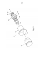
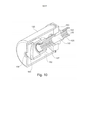
[055] As figuras 1 e 2 ilustram uma modalidade de um aparelho de bocal 10 da presente invenção compreendendo um aparelho de tela 20 (compreendendo um segregador de entrada 22 e uma tela principal 23), um corpo externo 30 e um recipiente de resíduos 40. Enquanto essa modalidade se refere ao fluxo de água para uso com um pulverizador, será apreciado que outros fluidos para finalidades diferentes também podem ser utilizados com tal aparelho de bocal 10 ou outro aparelho de bocal de acordo com a presente invenção.[055] Figures 1 and 2 illustrate an embodiment of a
[056] Os vários componentes 20, 30, 40, descritos em maiores detalhes abaixo, encaixam juntos ao longo de seu eixo geométrico central de modo que, como ilustrado na figura 1, o aparelho de bocal 10 possa ser fixado a uma peça em T 16 de um cano de água 14 ou qualquer saída de sistema de distribuição de fluido.[056] The
[057] Em uso, o cano de água 14 contém água poluída pelos resíduos parti- culados 18. Para a função básica, a água poluída flui através de uma passagem central 12 do aparelho de bocal 10 e a água continua através da tela principal 23 e através de uma saída ou canal de saída 36 que direciona a mesma para a área circundante. O resíduo particulado 18 que é muito grande para fluir através da tela principal 23, é direcionado para o recipiente referido como recipiente para resíduos 40. Dessa forma, o resíduo permanece fora do caminho da tela principal 23 o que evita o bloqueio da tela 23 ou bloqueio do canal de saída 36, permitindo, assim, que o aparelho de bocal 10 funcione adequadamente.[057] In use, the
[058] O recipiente para resíduos 40 pode ser removido e substituído periodicamente para remoção dos resíduos acumulados, que podem ser pesados para se calcular a taxa de corrosão como descrito abaixo.[058] The
[059] Os diferentes componentes do aparelho de bocal 10 serão agora descritos em maiores detalhes.[059] The different components of the
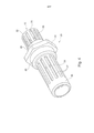
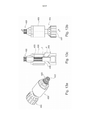
[060] O aparelho de tela 20, ilustrado em maiores detalhes nas figuras 4 e 5, compreendem um segregador de entrada 22 que compreende uma série de partições lineares 25, que permite que água e partículas menores percorram através da mesma, mas que bloqueia a passagem de partículas maiores. A tela principal 23 compreende uma série similar de partições 27 (apesar de tipicamente um pouco mais longas) que separa a água poluída em (i) uma corrente enriquecida com resíduos e (ii) uma corrente de água mais pura. O segregador de entrada 22 e a tela principal 23 são montados em alinhamento axial em cada lado de uma porca hexagonal 24. A passagem 12 se estende através do segregador de entrada 22, porca 24 e tela principal 23. Uma parte da porca 24 se estende radialmente para fora a partir do segregador de entrada 22 e tela principal 23, para fornecer um acessório para roscas 28, 29, acima e abaixo, como descrito aqui abaixo.[060] The
[061] O segregador de entrada 22 fornece capacidade adicional à capacidade de filtragem do aparelho de bocal 10, visto que os resíduos podem acumular entre a borda da peça em T 16 e o segregador de entrada 22. A passagem axial 12 (que é uma abertura maior do que as partições lineares 20) é fornecida no segrega- dor de entrada 22 através do qual a água além de as partículas de vários tamanhos podem fluir. Perceptivelmente, no entanto, a passagem 12 é grande o suficiente para receber as partículas maiores que não podem percorrer através das partições 25 no segregador de entrada 22. Dessa forma, se os resíduos 18 acumularem nessa posi- ção, os mesmos não bloquearão o fluxo de água de modo a não bloquear o aparelho de bocal geral 10. Dessa forma, quando os resíduos alcançam seu ponto de saturação, os mesmos começarão a fluir através do segregador de entrada 22 para dentro da passagem 12. O segregador de entrada 22 é particularmente adequado para bocais posicionados verticalmente.[061] The
[062] A corrente de água mais pura percorre através das partições 27 na tela principal 23 e para fora do canal de saída 36 e é direcionada pelo corpo externo 30 para a área circundante.[062] The purest water stream flows through the
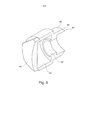
[063] Uma vista maior do corpo externo 30 é ilustrada na figura 6. A mesma compreende uma parte angulada 32, a parte interna 31 da qual, juntamente com uma parte combinada em um tubo 48, é formatada para direcionar o fluxo de água para a área desejada. A parte angulada 32 se estende radialmente para fora em comparação com o tubo oposto 48, mas isso não auxilia adicionalmente no direcionamento do fluxo de água. Ao invés disso, fornece uma maior superfície de agarre e possui um perfil sextavado para permitir o aperto da mesma à tela principal 23 para facilitar a montagem. O corpo 30 também inclui uma parte de cobertura 33 que define um percurso de fluxo entre seu orifício interno e a tela principal 23. O corpo externo 30 pode ser substituído por uma variedade de corpos diferentes de tamanhos variáveis e diferentes ângulos 31 a fim de ser dimensionado adequadamente para sua finalidade pretendida. Nessa modalidade, o corpo externo 30 fornece um jato cônico oco em um ângulo de 45 graus.[063] A larger view of the
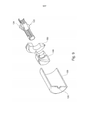
[064] O recipiente de resíduos 40 é ilustrado em maiores detalhes nas figuras 7 e 8 e compreende um recipiente 42 com uma placa de extremidade 44. Na extremidade aberta do recipiente de resíduos, um encaixe 46 é enroscado para receber uma rosca 26 na extremidade da tela principal 23 e uma parte de tubo de diâmetro maior (do que o encaixe) 48 se estende a partir do recipiente 42 adicionalmente na direção axial.[064] The
[065] Para se montar o aparelho de bocal 10 para a primeira utilização, o aparelho de tela 20 é afixado à peça em T 5 através de uma rosca 28 montada no flange de porca 24. O segregador de entrada 22, dessa forma, se estende ascendentemente para dentro da peça em T 5 ou outra tubulação à qual é encaixado e a tela principal 23 se estende a partir do lado oposto da porca 24 (normalmente em uma direção descendente). A parte de cobertura do corpo externo 30 é então colocada sobre e em torno da tela principal 23 e é afixada à rosca 29.[065] To assemble the
[066] A corrente de água mais pura percorre através das partições 27 na tela principal 23 e sai pelo canal de saída 36 e é direcionada pelo corpo externo 30 para a área circundante.[066] The purest water stream flows through the
[067] Uma vista maior do corpo externo 30 é ilustrada na figura 6. Compreende uma parte angulada 32, a parte interna 31 da qual, juntamente com uma parte combinada em um tubo 48, é formatada para direcionar o fluxo de água para a área desejada. A parte angulada 32 se estende radialmente para fora em comparação com o tubo oposto 48, mas isso não auxilia adicionalmente no direcionamento do fluxo de água. Ao invés disso, fornece uma superfície de agarre maior e possui um perfil sextavado para permitir o aperto do mesmo à tela principal 23 para facilitar a montagem. O corpo 30 também inclui uma parte de cobertura 33 que define um percurso de fluxo entre seu orifício interno e a tela principal 23. O corpo externo 30 pode ser substituído por uma variedade de corpos diferentes de tamanhos variáveis e ângulos diferentes 31 a fim de serem dimensionados adequadamente para seus fins pretendidos. Nessa modalidade, o corpo externo 30 fornece um jato cônico oco em um ângulo de 45 graus.[067] A larger view of the
[068] O recipiente de resíduos 40 é ilustrado em maiores detalhes nas figuras 7 e 8 e compreende um recipiente 42 com uma placa de extremidade 44. Em uma extremidade aberta do recipiente de resíduos, um encaixe 46 é enroscado para receber uma rosca 26 na extremidade da tela principal 23 e uma parte de tubo de diâmetro maior (do que o encaixe) 48 se estende a partir do recipiente 42 adicionalmente na direção axial.[068] The
[069] Para se montar o aparelho de bocal 10 para a primeira utilização, o aparelho de tela 20 é afixado à peça em T 5 através de uma rosca 28 montada no flange de porca 24. O segregador de entrada 22 se estende, dessa forma, ascendentemente para dentro da peça em T 5 ou outra tubulação à qual é encaixado e a tela principal 23 se estende a partir do lado oposto da porca 24 (normalmente em uma direção descendente). A parte de cobertura do corpo externo 30 é então localizadaatravés de e em torno da tela principal 23 e é afixada à rosca 29. Finalmente, o encaixe 46 no recipiente de resíduos 40 é fixado a uma rosca 26 na extremidade da tela principal 23. A borda 49 da parte de tubo 48 é então alinhada com e espaçada ligeiramente para longe da extremidade interna 31 do corpo externo 30 e o espaço resultante 18 (ilustrado na figura 1) entre os mesmos fornece o canal de saída 36 para a água. Perceptivelmente, a borda 49 é angulada para refletir o ângulo da extremidade de entrada 31 do corpo externo 30 (fornecendo, assim, um canal angulado), ambos os quais podem variar dependendo da cobertura desejada ou outros fatores.[069] To assemble the
[070] Para partículas de resíduos que são muito grandes para prosseguir através das partições 21, as mesmas prosseguem para o recipiente de resíduos 40. O recipiente 42 é dimensionado para permitir que um volume grande de resíduos seja aprisionado sob pressão.[070] For waste particles that are too large to proceed through the partitions 21, they proceed to the
[071] Dessa forma, as modalidades da presente invenção fornecem um ambiente livre de resíduos permitindo que a água passe através dos bocais, garantindo que alcance o Fator K necessário para seu desempenho ideal.[071] Thus, the modalities of the present invention provide a residue-free environment allowing water to pass through the nozzles, ensuring that it reaches the K Factor necessary for its optimal performance.
[072] As modalidades da presente invenção se beneficiam visto que para se bloquear completamente o bocal, serão necessárias quantidades muito grandes de resíduos sem manutenção para limpeza dos recipientes de resíduos, diferentemente de muitas soluções existentes que falharão quase que instantaneamente.[072] The embodiments of the present invention benefit since to completely block the nozzle, very large amounts of maintenance-free waste will be required for cleaning the waste containers, unlike many existing solutions that will fail almost instantly.
[073] Na verdade, para determinadas modalidades da invenção, existem doze partições na tela principal 23, mas o bocal ainda pode distribuir o volume e pressão de água necessários pelo bocal para seu desempenho ideal se apenas duas dessas partições estiverem livres de resíduos.[073] In fact, for certain embodiments of the invention, there are twelve partitions on the
[074] O canal de saída 36 pode ser determinado em qualquer ângulo. O ângulo nesse exemplo é de 45 graus, isso é específico para operações de resfriamento visto que envia água para frente em seu ângulo ideal para alcançar seu ponto mais distante da estrutura que está protegendo. Esse ângulo é combinado pelo tubo 48 do recipiente de resíduos 40 para formar o canal de saída 36. Preferivelmente, o recipiente de resíduos 40 não é maior do que o corpo externo 32.[074]
[075] A tela principal 23 e a cobertura 33 são dimensionadas para otimizar o volume de água correto e pressão para o canal de saída 36.[075]
[076] A primeira modalidade é ilustrada fixada a uma peça em T, mas o aparelho de bocal pode se fixar facilmente a qualquer saída de transferência de fluido - um ponto de saída vertical voltado para cima ou para baixo - horizontal, etc. também pode ser utilizado.[076] The first modality is illustrated attached to a T-piece, but the nozzle apparatus can easily attach to any fluid transfer outlet - a vertical outlet point facing up or down - horizontal, etc. can also be used.
[077] A figura 9 ilustra uma segunda modalidade de um aparelho de bocal 110 da presente invenção, partes similares compartilham a mesma referência numérica exceto pelo fato de serem precedidas por um "1". O aparelho de bocal 110 compreende um aparelho de tela 120, um corpo externo 130 e um recipiente de resíduos 140.[077] Figure 9 illustrates a second embodiment of a nozzle apparatus 110 of the present invention, similar parts share the same numerical reference except that they are preceded by a "1". The nozzle apparatus 110 comprises a
[078] O aparelho de tela 120 e o recipiente de resíduos 140 funcionam como descrito para a modalidade anterior, e não serão descritos adicionalmente.[078] The
[079] Nessa modalidade, no entanto, o corpo externo 130 é um formato cilíndrico com uma extremidade aberta e a extremidade oposta possuindo um canal de saída 136. O corpo externo 130 encerra a armadilha de resíduos 140, e é preso con- tra um elemento de suporte 150, que, por sua vez, é preso a uma porca de extensão circunferencial 124 no aparelho de tela 120.[079] In this modality, however, the
[080] O aparelho de bocal montado 110 é ilustrado na figura 10. Em uso, a água (ou outro fluido) entra no aparelho de bocal através de um segregador de entrada 122, que impede o fluxo de partículas de resíduo através de suas partições menores 125. O fluxo continua através da passagem central 112 do aparelho de tela 120, através das partições 127 na tela principal 123 e então para dentro de um espaço vazio 152 entre o corpo externo 130 e o recipiente de resíduos 140/tela principal 123. Os resíduos particulados muito grandes para prosseguir através das partições 127 residem no recipiente de resíduos 140. O fluxo de água continua para fora pelo canal de saída 136, que pode ser adequadamente dimensionado para aplicação desejada, por exemplo, criando uma névoa. Essa disposição permite um perfil de pulverização cônico completo.[080] The assembled nozzle apparatus 110 is illustrated in Figure 10. In use, water (or other fluid) enters the nozzle apparatus through an
[081] Uma vantagem de determinadas modalidades da invenção é que as telassão fornecidas no aparelho de bocal perto do canal de saída. Portanto, poluentes (tal como os resíduos que saem da tubulação) são apanhados na tubulação. Isso contrasta com outros modelos onde uma tela ou filtro é fornecido a montante na tubulação e qualquer resíduo liberado a jusante da tela não é peneirado e, dessa forma, pode bloquear os bocais.[081] An advantage of certain embodiments of the invention is that the screens are provided in the mouthpiece apparatus close to the outlet channel. Therefore, pollutants (such as waste coming out of the pipeline) are trapped in the pipeline. This contrasts with other models where a screen or filter is provided upstream in the pipeline and any residue released downstream of the screen is not sieved and thus can block the nozzles.
[082] Alguns aparelhos de tela alternativos 220, 320 são ilustrados nas figuras 11 e 12 e os mesmos funcionam de forma similar às modalidades anteriores. Na figura 12, pode ser observado que as partições 325, 327 são dispostas em uma direção perpendicular ao fluxo de fluido em contraste com as modalidades anteriores.[082] Some
[083] Em qualquer caso, a disposição das partições para modalidades preferidas da invenção, é configurada de modo que o comprimento do corpo externo e a passagem através da tela permitam um volume suficiente através da saída mesmo se 80% da tela estiver bloqueada. O fornecimento de partições ao invés de telas de furo circular pequenas, facilita tal efeito, que também minimiza o acúmulo de pressão na tela e pressão perdida a partir do fluido expelido.[083] In any case, the arrangement of partitions for preferred embodiments of the invention is configured so that the length of the outer body and the passage through the screen allow sufficient volume through the outlet even if 80% of the screen is blocked. Providing partitions instead of small circular hole screens facilitates this effect, which also minimizes pressure build-up on the screen and pressure lost from the expelled fluid.
[084] Não apenas as modalidades da presente invenção permitem o armazenamento de resíduos, mas também podem ser utilizadas para determinar a taxa de corrosão dentro da linha deluge. Depois que cada teste de função do sistema, todos os recipientes de resíduos podem ser removidos com os resíduos sendo armazenados para pesagem. O peso e volume dos resíduos podem ser calculados para mostrar a taxa de corrosão quando referidos com a frequência do teste. Essa característica permitirá que o operador avalie a vida útil de todo o sistema e determine quando precisa de uma reestruturação e substituição completa.[084] Not only do the modalities of the present invention allow for the storage of waste, but they can also be used to determine the rate of corrosion within the deluge line. After each system function test, all waste containers can be removed with the waste being stored for weighing. The weight and volume of residues can be calculated to show the corrosion rate when referenced with the test frequency. This feature will allow the operator to assess the life of the entire system and determine when it needs a complete overhaul and replacement.
[085] Uma modalidade adicional da invenção é ilustrada nas figuras 13a a 13c e partes similares utilizam os números de referência correspondentes de modalidades anteriores exceto pelo fato de serem precedidos por um "4". A modalidade da figura 13a compreende um segregador de entrada 422, um corpo principal 430 e um recipiente de resíduos 440 que funcionam como descrito para modalidades anteriores a menos que notado o contrário.[085] A further embodiment of the invention is illustrated in figures 13a to 13c and similar parts use the corresponding reference numbers of previous embodiments except that they are preceded by a "4". The embodiment of Figure 13a comprises an
[086] Perceptivelmente, um canal de saída 436 é fornecido entre a tela 423 e o alojamento 430, que é maior e direciona o fluido que passou através da tela 423 na direção do recipiente de resíduos 440.[086] Perceptibly, an
[087] O recipiente de resíduos 440 possui uma pluralidade de partições 447 no perímetro externo do mesmo. Cada partição 447 se estende verticalmente (como orientado durante o uso) e na direção do centro do recipiente de resíduos 430 tipicamente por 5 a 25 mm. Dessa forma, são radialmente espaçados um do outro.[087] The
[088] Em uso, o fluido relativamente puro é direcionado da saída 436 para o recipiente de resíduos 430, que distribui o fluido para dentro de um padrão necessário em determinadas situações. O fluido seguirá o percurso do modelo da face externa do recipiente de resíduos 440 onde pode fluir através do mesmo e atingir as se- ções direcionando o fluxo em várias direções. Isso determinará se o padrão é um padrão de cone oco ou cone cheio. A alta velocidade é normalmente um cone cheio a menos que o alojamento 430 circule a área de recipiente de resíduos total (de acordo com a modalidade da figura 10).[088] In use, relatively pure fluid is directed from
[089] As distâncias "c" e "d" podem variar dependendo das exigências de aplicação. Por exemplo, d pode ser inferior ao que é ilustrado nas figuras e é tipicamente de 1 a 20 mm.[089] Distances "c" and "d" may vary depending on application requirements. For example, d may be smaller than shown in the figures and is typically 1 to 20 mm.
[090] A velocidade pode ser reduzida pela extensão do comprimento "d"entre a saída 436 e o recipiente de resíduos 440. Para se reduzir o fluxo para reduzir o Fator K ou vice-versa, as partições na tela 423 podem ser em menor número: 12 partições de 1 mm de largura através da mesma área ao invés de 24 partições de 1 mm, por exemplo. Isso reduz o volume.[090] Speed can be reduced by extending length "d" between
[091] Uma modalidade adicional da invenção é ilustrada nas figuras 14a a 14c e partes similares utilizam as referências numéricas correspondentes de modalidades anteriores exceto pelo fato de serem precedidos por um "5". A modalidade da figura 14a compreende um segregador de entrada 522, um corpo principal 530 e um recipiente de resíduos 540 que funciona como descrito para modalidades anteriores a menos que notado o contrário.[091] A further embodiment of the invention is illustrated in figures 14a to 14c and similar parts use the corresponding reference numerals from previous embodiments except that they are preceded by a "5". The embodiment of Figure 14a comprises an
[092] Nessa modalidade, o aparelho de bocal é orientado em uma direção ascendente durante o uso e a pressão mantem os resíduos no recipiente de resíduos 540. O recipiente de resíduos 540 possui um flange angulado 545 que tem cerca de 80 graus para o alojamento 540.[092] In this embodiment, the nozzle apparatus is oriented in an upward direction during use and the pressure holds the waste in the
[093] Em uso, o fluido prossegue através do segregador de entrada 522, através da tela principal 523 e de entre o alojamento 530 e a tela principal 523 é então direcionado pela parte angulada 545 do recipiente de resíduos 540 para fora do aparelho através de uma saída 536.[093] In use, the fluid proceeds through the
[094] O aparelho de bocal ilustrado nas figuras 13a a c e 14a a c é frequen- temente mais adequado para aplicações de velocidades de médias à altas, ou aplicações de velocidades de médias à baixas, em comparação com o aparelho de bocal das modalidades anteriores que são mais adequados para aplicações em alta velocidade. Não obstante, qualquer modalidade pode ser utilizada para qualquer aplicação de velocidade.[094] The nozzle apparatus illustrated in Figures 13a ace 14a ac is often more suitable for medium to high speed applications, or medium to low speed applications, compared to the nozzle apparatus of the previous embodiments which are best suited for high speed applications. However, any mode can be used for any speed application.
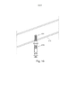
[095] A figura 15 ilustra uma modalidade adicional de um aparelho de bocal 610 possuindo uma entrada estendida 631. A entrada dessa modalidade se estende para dentro de uma tubulação 614, como ilustrado nas figuras 16 e 17, de modo que a entrada se estenda para o centro da tubulação. Dessa forma, mesmo com os resíduos acumulados no interior da tubulação 614, que tenderia a bloquear outros bocais,não bloqueará desde que o fluido esteja fluindo através do centro da tubulação 614. Tal configuração pode ser utilizada com qualquer um dos bocais descritos aqui. Nessa modalidade, a extremidade da entrada 631 está dentro de 5 mm do eixo geométrico central da tubulação 614 que possui um diâmetro de 1" a 8".[095] Figure 15 illustrates an additional embodiment of a
[096] A entrada 631 também possui uma parte secundária 622, que permite que o fluido flua, e também compreende uma série de partições de forro 625 para filtrar o fluido.[096]
[097] A figura 18 ilustra o aparelho de bocal da figura 15 com o alojamento externo removido, ilustrando alguns componentes internos, que geralmente funcionam como descrito para modalidades anteriores.[097] Figure 18 illustrates the nozzle apparatus of Figure 15 with the external housing removed, illustrating some internal components, which generally function as described for previous embodiments.
[098] Perceptivelmente, a entrada 631 é fornecida como uma peça separada, e durante a montagem é localizada dentro da tubulação. As partes restantes do aparelho de bocal são então conectadas à peça de entrada separada 631.[098] Perceptibly,
[099] A presente modalidade também inclui uma placa de dispersão 658 conectada ao recipiente por um elemento cilíndrico.[099] The present embodiment also includes a
[0100] As modalidades da invenção possuem múltiplos usos sendo capazes de alcançar o Fator K para o pulverizador.[0100] The embodiments of the invention have multiple uses being able to achieve the K Factor for the sprayer.
[0101] As modalidades da invenção também são mais seguras visto que menosresíduos são distribuídos para fora com o fluido. Tais resíduos podem causar danos ao pessoal, por exemplo, se tem conhecimento de ferimentos faciais e têm o potencial de causar sérios danos oculares.[0101] The embodiments of the invention are also safer since less waste is distributed out with the fluid. Such residues can cause harm to personnel, for example, if they are aware of facial injuries and have the potential to cause serious eye damage.
[0102] Aperfeiçoamentos e modificações podem ser feitos sem se distanciar do escopo da invenção.[0102] Improvements and modifications can be made without departing from the scope of the invention.
Claims (20)
Applications Claiming Priority (7)
| Application Number | Priority Date | Filing Date | Title |
|---|---|---|---|
| GB201212199A GB201212199D0 (en) | 2012-07-09 | 2012-07-09 | Nozzle apparatus |
| GB1212199.2 | 2012-07-09 | ||
| GB1218133.5 | 2012-10-10 | ||
| GB201218133A GB201218133D0 (en) | 2012-07-09 | 2012-10-10 | Improved nozzle apparatus |
| GB201308561A GB201308561D0 (en) | 2012-07-09 | 2013-05-13 | Nozzle apparatus and nozzle system |
| GB1308561.8 | 2013-05-13 | ||
| PCT/GB2013/051811 WO2014009713A1 (en) | 2012-07-09 | 2013-07-09 | Nozzle apparatus |
Publications (2)
| Publication Number | Publication Date |
|---|---|
| BR112015000414A2 BR112015000414A2 (en) | 2017-06-27 |
| BR112015000414B1 true BR112015000414B1 (en) | 2021-08-31 |
Family
ID=46766382
Family Applications (2)
| Application Number | Title | Priority Date | Filing Date |
|---|---|---|---|
| BR112015000414-8A BR112015000414B1 (en) | 2012-07-09 | 2013-07-09 | NOZZLE APPLIANCE, USE OF THE APPLIANCE AND PIPING INTEGRITY MONITORING METHOD |
| BR112015000415-6A BR112015000415B1 (en) | 2012-07-09 | 2013-07-09 | sprinkler system comprising a sprinkler and piping |
Family Applications After (1)
| Application Number | Title | Priority Date | Filing Date |
|---|---|---|---|
| BR112015000415-6A BR112015000415B1 (en) | 2012-07-09 | 2013-07-09 | sprinkler system comprising a sprinkler and piping |
Country Status (14)
| Country | Link |
|---|---|
| US (2) | US10690577B2 (en) |
| EP (2) | EP2869936B1 (en) |
| JP (2) | JP2015527191A (en) |
| CN (1) | CN104602822B (en) |
| AU (2) | AU2013288469B2 (en) |
| BR (2) | BR112015000414B1 (en) |
| CA (2) | CA2878723A1 (en) |
| DK (2) | DK2869935T3 (en) |
| EA (2) | EA201590181A1 (en) |
| GB (3) | GB201212199D0 (en) |
| MX (2) | MX2015000374A (en) |
| MY (1) | MY194235A (en) |
| SG (2) | SG11201500120YA (en) |
| WO (2) | WO2014009714A1 (en) |
Families Citing this family (7)
| Publication number | Priority date | Publication date | Assignee | Title |
|---|---|---|---|---|
| GB201212199D0 (en) | 2012-07-09 | 2012-08-22 | Rigdeluge Global Ltd | Nozzle apparatus |
| JP6081934B2 (en) * | 2014-01-24 | 2017-02-15 | 東京エレクトロン株式会社 | Treatment liquid nozzle and coating treatment apparatus |
| GB201406174D0 (en) * | 2014-04-04 | 2014-05-21 | Rigdeluge Global Ltd | Filter |
| DE102014004958A1 (en) | 2014-04-05 | 2015-10-08 | Martin Rebhan | Intake intermediate filter and header for extinguishing water purification |
| DE102015214123B3 (en) * | 2015-07-27 | 2016-07-14 | Lechler Gmbh | Filter for high-pressure nozzle, high-pressure nozzle and method for producing a filter for a high-pressure nozzle |
| GB201517760D0 (en) * | 2015-10-07 | 2015-11-18 | Rigdeluge Global Ltd | Nozzle apparatus |
| GB2549965B (en) * | 2016-05-04 | 2019-07-17 | Rigdeluge Global Ltd | Hybrid nozzle |
Family Cites Families (60)
| Publication number | Priority date | Publication date | Assignee | Title |
|---|---|---|---|---|
| CA492585A (en) | 1953-05-05 | E. Bartling Loren | Nozzle support for spray boom | |
| US1617858A (en) * | 1923-03-30 | 1927-02-15 | George E March | Screen for nozzles |
| US1508480A (en) | 1923-04-27 | 1924-09-16 | Charles W Skinner | Trap filter for irrigation |
| US1563490A (en) | 1924-10-03 | 1925-12-01 | Horton Spencer | Sprinkler installation |
| US2493982A (en) | 1948-03-26 | 1950-01-10 | Akron Brass Mfg Company Inc | Spray head for fire sprinkler systems |
| US2629632A (en) | 1948-10-28 | 1953-02-24 | H Munson Ralph | Spray nozzle |
| US3268176A (en) * | 1964-08-07 | 1966-08-23 | Spraying Systems Co | Spray nozzle having stabilizing tube and vane unit |
| US3273805A (en) | 1964-10-02 | 1966-09-20 | Ingersoll Rand Co | Pressurized fluid nozzle assembly |
| US3672578A (en) | 1970-08-20 | 1972-06-27 | Delavan Manufacturing Co | Nozzle |
| FR2229211A5 (en) | 1973-05-07 | 1974-12-06 | Desmarquest & Cec | Anti drip spray nozzle for agricultural use - flexible sleeve normally closed over supply holes is opened by press. |
| US4064046A (en) | 1976-06-02 | 1977-12-20 | Lloyd Dwight Gilger | Self-cleaning filter apparatus |
| US4331293A (en) * | 1979-11-23 | 1982-05-25 | Rangel Garza Javier | Emitters for drip irrigation systems, micro-sprinklers and similars, of the pressure compensating type and also those types whose flow varies in relation to the changes in pressure |
| GB2142105B (en) | 1983-06-25 | 1986-06-04 | Spraytec Engineering Limited | Water supply means |
| JPS6164732A (en) | 1984-09-06 | 1986-04-03 | Osaka Soda Co Ltd | Bonding of rubber |
| JPS62174652A (en) | 1986-01-28 | 1987-07-31 | Mitsubishi Metal Corp | Decrepitation measuring instrument by acoustic emission |
| JPH0344268Y2 (en) * | 1986-04-28 | 1991-09-18 | ||
| AU610098B2 (en) * | 1986-12-11 | 1991-05-16 | Spraying Systems Co. | Convertible spray nozzle |
| JPH0673697B2 (en) | 1987-10-24 | 1994-09-21 | 株式会社共立合金製作所 | Nozzle for scale removal |
| DE3741677A1 (en) * | 1987-10-24 | 1989-05-03 | Kyoritsu Gokin Mfg | Descaling jet pipe |
| JPH01125072A (en) | 1987-11-09 | 1989-05-17 | Matsushita Electric Ind Co Ltd | Solid-state image pickup device |
| JPH0367799U (en) * | 1989-10-27 | 1991-07-02 | ||
| US5269913A (en) * | 1991-10-02 | 1993-12-14 | Zarina Holding C.V. | Debris trap |
| JPH0852386A (en) * | 1994-08-10 | 1996-02-27 | Kyoritsu Gokin Seisakusho:Kk | Fluid jetting nozzle apparatus |
| US5762269A (en) | 1996-05-14 | 1998-06-09 | Nelson Irrigation Corporation | Nozzle clip |
| US5839667A (en) | 1997-03-12 | 1998-11-24 | Grinnell Corporation | Pendent-type diffuser impingement water mist nozzle |
| US5863443A (en) * | 1997-06-16 | 1999-01-26 | Mainwaring; Timothy | In-line agricultural water filter with diverter tube and flush valve |
| SE510679C2 (en) | 1997-08-29 | 1999-06-14 | Trelleborg Viking Asa | Pipe or hose that can withstand high heat flux density and use of the pipe or hose |
| JP2001113110A (en) * | 1999-10-20 | 2001-04-24 | Yamato Valve:Kk | Strainer |
| IT1318617B1 (en) * | 2000-07-10 | 2003-08-27 | Novara Technology Srl | SOL-GEL PROCESS FOR THE PRODUCTION OF LARGE DRIED GELS AND DERIVED GLASS. |
| US6575307B2 (en) | 2000-10-10 | 2003-06-10 | Rain Bird Corporation | Self-cleaning water filter |
| US6450266B1 (en) | 2001-01-24 | 2002-09-17 | The Reliable Automatic Sprinkler Co., Inc. | Sprinkler arrangement for document storage |
| DE20103812U1 (en) | 2001-03-06 | 2001-08-09 | Systemtechnik Herzog GmbH, 39387 Oschersleben | Swirl nozzle for generating spray mist |
| JP2003159549A (en) | 2001-09-12 | 2003-06-03 | Ikeuchi:Kk | Spray nozzle |
| CA2485118C (en) | 2002-12-25 | 2010-04-27 | Kyoritsu Gokin Co., Ltd. | Descaling nozzle |
| DE20301377U1 (en) * | 2003-01-30 | 2003-05-28 | Herzog, Hans-Joachim, 39387 Oschersleben | Connector for sprinkler system has lateral connections for flat profile misting jets |
| CN2613319Y (en) | 2003-03-31 | 2004-04-28 | 首安工业消防股份有限公司 | Thin spray nozzle |
| US7299999B2 (en) | 2003-04-02 | 2007-11-27 | Rain Bird Corporation | Rotating stream sprinkler with torque balanced reaction drive |
| US6951286B2 (en) | 2003-06-20 | 2005-10-04 | Mueller John R | Showerhead and filter assembly |
| US7000782B2 (en) * | 2003-12-05 | 2006-02-21 | Dosmatic Usa, Inc. | Backwash flushing filter |
| GB0405088D0 (en) | 2004-03-05 | 2004-04-07 | Optima Solutions Uk Ltd | Improved nozzle |
| GB2433710B (en) | 2004-03-05 | 2007-11-14 | Optima Solutions Uk Ltd | Nozzle having a fluid deflector |
| GB2441058B (en) | 2004-03-05 | 2008-08-27 | Optima Solutions Uk Ltd | Nozzle with fluid deflector arrangement |
| US7219684B2 (en) * | 2005-01-28 | 2007-05-22 | Rain Bird Corporation | Saddle tee and tool for irrigation lines |
| US8919678B2 (en) | 2006-04-18 | 2014-12-30 | American Agriculture Products, Llc | Filtration and cleaning system for sprinkler irrigation drop nozzles |
| US7900854B2 (en) * | 2006-04-18 | 2011-03-08 | American Agriculture Products, Llc | Filtration and cleaning system for sprinkler irrigation drop nozzles |
| DE102007024247B3 (en) | 2007-05-15 | 2008-11-06 | Lechler Gmbh | High pressure nozzle and method of making a high pressure nozzle |
| DE102007024245B3 (en) | 2007-05-15 | 2008-08-28 | Lechler Gmbh | Spray nozzle i.e. high pressure nozzle for descaling steel products, has outlet clamping curved surface, and another surface abutting against boundary of outlet in radial direction at specific angle to central longitudinal axis |
| GB0804432D0 (en) | 2008-03-11 | 2008-04-16 | Rigcool Ltd | Boom |
| US7913937B2 (en) * | 2008-05-02 | 2011-03-29 | Spraying Systems Co. | Descaling spray nozzle assembly |
| JP2010221257A (en) * | 2009-03-24 | 2010-10-07 | Kyoritsu Gokin Co Ltd | Spray nozzle and structure of its filter |
| CN201524483U (en) | 2009-09-15 | 2010-07-14 | 郭爱华 | Well head filter of pumping well |
| JP5663276B2 (en) * | 2010-11-18 | 2015-02-04 | ホーチキ株式会社 | Tunnel water spray equipment and strainer equipment |
| US20120125867A1 (en) | 2010-11-24 | 2012-05-24 | Delaware Capital Formation, Inc. | Flushable filter device |
| CN201949711U (en) * | 2011-02-17 | 2011-08-31 | 上海大屯能源股份有限公司 | Sundry filter of water spraying device |
| JP6102170B2 (en) * | 2011-12-22 | 2017-03-29 | Jfeスチール株式会社 | Nozzle filter and spray nozzle for spray nozzle |
| GB2501886B (en) | 2012-05-08 | 2015-12-02 | Techtronic Floor Care Tech Ltd | Steam cleaners |
| US9462994B2 (en) | 2012-05-11 | 2016-10-11 | 3M Innovative Properties Company | Bioacoustic sensor with active noise correction |
| GB201212199D0 (en) | 2012-07-09 | 2012-08-22 | Rigdeluge Global Ltd | Nozzle apparatus |
| CN202667021U (en) | 2012-07-11 | 2013-01-16 | 陈延芬 | Filtering device of micro-fog nozzle |
| GB201406174D0 (en) | 2014-04-04 | 2014-05-21 | Rigdeluge Global Ltd | Filter |
-
2012
- 2012-07-09 GB GB201212199A patent/GB201212199D0/en not_active Ceased
- 2012-10-10 GB GB201218133A patent/GB201218133D0/en not_active Ceased
-
2013
- 2013-05-13 GB GB201308561A patent/GB201308561D0/en not_active Ceased
- 2013-07-09 EA EA201590181A patent/EA201590181A1/en unknown
- 2013-07-09 MX MX2015000374A patent/MX2015000374A/en unknown
- 2013-07-09 WO PCT/GB2013/051812 patent/WO2014009714A1/en active Application Filing
- 2013-07-09 US US14/413,287 patent/US10690577B2/en active Active
- 2013-07-09 WO PCT/GB2013/051811 patent/WO2014009713A1/en active Application Filing
- 2013-07-09 BR BR112015000414-8A patent/BR112015000414B1/en active IP Right Grant
- 2013-07-09 CN CN201380046482.8A patent/CN104602822B/en active Active
- 2013-07-09 JP JP2015521061A patent/JP2015527191A/en active Pending
- 2013-07-09 EA EA201590182A patent/EA036454B1/en not_active IP Right Cessation
- 2013-07-09 AU AU2013288469A patent/AU2013288469B2/en active Active
- 2013-07-09 SG SG11201500120YA patent/SG11201500120YA/en unknown
- 2013-07-09 DK DK13750091.4T patent/DK2869935T3/en active
- 2013-07-09 AU AU2013288470A patent/AU2013288470B2/en active Active
- 2013-07-09 BR BR112015000415-6A patent/BR112015000415B1/en active IP Right Grant
- 2013-07-09 CA CA2878723A patent/CA2878723A1/en not_active Abandoned
- 2013-07-09 CA CA2878724A patent/CA2878724C/en active Active
- 2013-07-09 US US14/413,278 patent/US9833804B2/en active Active
- 2013-07-09 DK DK13750359.5T patent/DK2869936T3/en active
- 2013-07-09 EP EP13750359.5A patent/EP2869936B1/en active Active
- 2013-07-09 SG SG11201500121TA patent/SG11201500121TA/en unknown
- 2013-07-09 MX MX2015000372A patent/MX2015000372A/en unknown
- 2013-07-09 JP JP2015521062A patent/JP2015531670A/en active Pending
- 2013-07-09 EP EP13750091.4A patent/EP2869935B1/en active Active
- 2013-07-09 MY MYPI2015700089A patent/MY194235A/en unknown
Also Published As
Similar Documents
| Publication | Publication Date | Title |
|---|---|---|
| BR112015000414B1 (en) | NOZZLE APPLIANCE, USE OF THE APPLIANCE AND PIPING INTEGRITY MONITORING METHOD | |
| JP2015527191A5 (en) | ||
| EP2629873B1 (en) | Device including a compact spray nozzle for cleaning a filter cloth in a disc filter | |
| RU2672411C1 (en) | Two-step dust collector system with inertial dust separator | |
| ITUA20164226A1 (en) | WASHING OR FILTRATION SYSTEM OF A GAS CURRENT | |
| CN108351057B (en) | Pipe arrangement comprising a reducing bush | |
| RU2654734C1 (en) | Conical jet scrubber with vortex sprayer | |
| RU77172U1 (en) | FILTER | |
| CN104619428B (en) | Spray nozzle device | |
| RU2550831C1 (en) | Scrubber by kochetov | |
| GB2507728A (en) | A trap for collecting debris | |
| WO2018022812A1 (en) | Filter adapter | |
| BR102018011146A2 (en) | DEVICE FOR DRAINAGE AND SEALING OF MIST ELIMINATORS | |
| CN109562396A (en) | Sprinkler part and discharging device | |
| RU2512941C1 (en) | Scrubber with movable attachment | |
| GB2503885A (en) | Nozzle Apparatus for a deluge system on a flare boom | |
| RU2635155C1 (en) | Scrubber | |
| RU2490054C1 (en) | Scrubber with moving nozzle | |
| RU2019142351A (en) | VORTEX COLLECTOR DUST COLLECTOR | |
| BR112020004491B1 (en) | IRRIGATION SYSTEM, DEVICE FOR AN IRRIGATION SYSTEM, DISTRIBUTOR ARM AND PERFORATED PLATE | |
| CN110709140A (en) | Foam former and foam sprayer | |
| PL235974B1 (en) | Vortex liquid flow regulator |
Legal Events
| Date | Code | Title | Description |
|---|---|---|---|
| B06F | Objections, documents and/or translations needed after an examination request according [chapter 6.6 patent gazette] | ||
| B06U | Preliminary requirement: requests with searches performed by other patent offices: procedure suspended [chapter 6.21 patent gazette] | ||
| B09A | Decision: intention to grant [chapter 9.1 patent gazette] | ||
| B16A | Patent or certificate of addition of invention granted [chapter 16.1 patent gazette] |
Free format text: PRAZO DE VALIDADE: 20 (VINTE) ANOS CONTADOS A PARTIR DE 09/07/2013, OBSERVADAS AS CONDICOES LEGAIS. |