BR112014020854B1 - TRANSPORTATION APPLIANCE FOR TRANSPORTATION OF HEAVY OBJECTS - Google Patents
TRANSPORTATION APPLIANCE FOR TRANSPORTATION OF HEAVY OBJECTS Download PDFInfo
- Publication number
- BR112014020854B1 BR112014020854B1 BR112014020854-9A BR112014020854A BR112014020854B1 BR 112014020854 B1 BR112014020854 B1 BR 112014020854B1 BR 112014020854 A BR112014020854 A BR 112014020854A BR 112014020854 B1 BR112014020854 B1 BR 112014020854B1
- Authority
- BR
- Brazil
- Prior art keywords
- transport apparatus
- wheel
- chassis
- wheel axle
- transport
- Prior art date
Links
- 238000004642 transportation engineering Methods 0.000 title abstract 3
- 210000001503 Joints Anatomy 0.000 claims description 19
- 229910000831 Steel Inorganic materials 0.000 claims description 8
- 239000010959 steel Substances 0.000 claims description 8
- 230000005540 biological transmission Effects 0.000 claims 1
- 238000005303 weighing Methods 0.000 description 6
- 210000002105 Tongue Anatomy 0.000 description 5
- 238000010276 construction Methods 0.000 description 5
- 238000004519 manufacturing process Methods 0.000 description 4
- 239000000203 mixture Substances 0.000 description 3
- 230000035882 stress Effects 0.000 description 3
- 238000007906 compression Methods 0.000 description 2
- 238000009826 distribution Methods 0.000 description 2
- 239000007787 solid Substances 0.000 description 2
- 230000000712 assembly Effects 0.000 description 1
- 230000000903 blocking Effects 0.000 description 1
- 239000000969 carrier Substances 0.000 description 1
- JOYRKODLDBILNP-UHFFFAOYSA-N ethyl urethane Chemical compound CCOC(N)=O JOYRKODLDBILNP-UHFFFAOYSA-N 0.000 description 1
- 230000014759 maintenance of location Effects 0.000 description 1
- 239000000463 material Substances 0.000 description 1
- 238000000034 method Methods 0.000 description 1
- 230000004048 modification Effects 0.000 description 1
- 238000006011 modification reaction Methods 0.000 description 1
- 230000000284 resting Effects 0.000 description 1
- 230000000717 retained Effects 0.000 description 1
- 239000000725 suspension Substances 0.000 description 1
Images


Abstract
APARELHO DE TRANSPORTE PARA TRANSPORTAMENTO DE OBJETOS PESADOS. A presente invenção se refere a um aparelho de transporte para transportamento de objetos pesados, no qual aparelho de transporte (10) inclui: - um chassi (12), que inclui pelo menos duas partes laterais (16) e uma parte de plataforma (20) e parte traseira (14') dentre as mesmas; - um espaço de carga (21) disposto na metade do chassi (12) sobre o topo da parte de plataforma (20) para a superfície de suporte (106) do objeto (100) a ser transportado; e - pelo menos uma roda (22) montada sobre cada lateral do espaço de carga (21) do chassi (12), com o auxílio de um eixo de rodas. Em concordância com a presente invenção, o chassi (12) inclui em adição uma parte dianteira (14) e segundas partes laterais (18), do qual as segundas partes laterais (18), a parte dianteira (14), e a parte traseira (14') juntamente formam uma estrutura (27) englobada sobre o plano horizontal, estrutura (27) no interior da qual é localizada pelo menos em uma roda sobre cada lateral do espaço de carga (21), seu eixo de rodas (26) sendo suportado sobre pelo menos a segunda parte lateral (18).TRANSPORTATION APPLIANCE FOR TRANSPORTING HEAVY OBJECTS. The present invention relates to a transport apparatus for transporting heavy objects, in which transport apparatus (10) includes: - a chassis (12), which includes at least two side parts (16) and a platform part (20 ) and rear (14') between them; - a load space (21) arranged in the half of the chassis (12) over the top of the platform part (20) for the support surface (106) of the object (100) to be transported; and - at least one wheel (22) mounted on each side of the load space (21) of the chassis (12), with the aid of a wheel axle. In accordance with the present invention, the chassis (12) further includes a front (14) and second side portions (18), of which the second side portions (18), the front portion (14), and the rear portion (14') together form a frame (27) encompassed over the horizontal plane, frame (27) within which at least one wheel is located on each side of the cargo space (21) its wheel axle (26) being supported on at least the second side part (18).
Description
[001] A presente invenção se refere a um aparelho de transporte para transportamento de objetos pesados, particularmente uma máquina de trabalho, especialmente uma escavadeira, se movimentando sobre esteiras e equipado com um dispositivo de escavadeira ou outro elemento de elevação, aparelho de transporte que inclui:- um chassi, que inclui pelo menos duas partes laterais e uma parte de plataforma e parte traseira dentre as mesmas;- um espaço de carga disposto na metade do chassi sobre o topo da parte de plataforma para a superfície de suporte do objeto a ser transportado; e- pelo menos uma roda sobre cada lateral do espaço de carga do chassi, montada sobre o chassi com o auxilio de um eixo de rodas.[001] The present invention relates to a transport apparatus for transporting heavy objects, particularly a working machine, especially an excavator, moving on tracks and equipped with an excavator device or other lifting element, transport apparatus that includes: - a chassis, which includes at least two side parts and a platform part and a rear part thereof; - a cargo space arranged in the half of the chassis over the top of the platform part for the supporting surface of the object to be transported; and - at least one wheel on each side of the chassis load space, mounted on the chassis with the aid of a wheel axle.
[002] Tradicionalmente, escavadeiras e carregadores similares são movimentáveis com o auxilio de uma subestrutura (subtransportador) de esteira. Transportamento de longa distância é um problema com carregadores equipados com uma subestrutura de esteira. Tração em longas distâncias sobre uma subestrutura de esteira desgasta a subestrutura e é extremamente lenta. Transportamento, transportador. Entretanto, isto requer um transportador especial, sobre o qual o transportamento acontece.[002] Traditionally, excavators and similar loaders are movable with the aid of a sub-frame (sub-conveyor) of track. Long-distance transport is an issue with loaders equipped with a track sub-frame. Long-distance traction on a track sub-frame wears out the sub-frame and is extremely slow. Transport, conveyor. However, this requires a special transporter, over which the transport takes place.
[003] Conhecida a partir do estado da técnica existe a publicação de patente finlandesa número FI 101 779 B, que apresenta aparelhos de transporte separados, sobre o topo dos quais a subestrutura de esteira de um carregador é fracionada durante a duração do transportamento. Existe um aparelho de transporte para cada esteira da subestrutura de esteira. 0 carregador é suportado por sua lança (longarina) sobre uma máquina de trabalho, por exemplo, um caminhão de lixo, que reboca o carregador depois dele. O aparelho de transporte inclui um chassi formando um espaço de esteira e rodas montadas sobre ambas as laterais do chassi. Entretanto, uma tal solução apresenta uma desvantagem de uma capacidade de carregamento de carga limitada, que limita o peso dos carregadores sendo transportados para cerca de 400 toneladas. Com carregadores maiores do que estes, o suporte dos eixos de rodas das rodas de transporte tem que ser reforçado em uma extensão tal de maneira a aumentar a largura global das rodas de transporte. A distância entre as rodas de transporte de ambas as esteiras é excessivamente reduzida de modo que as rodas de transporte podem bater (se chocar) umas com as outras quando os eixos de rodas se inclinam de uma maneira não sincronizada devido para o fato de irregularidades de solo. Alternativamente, pode também acontecer que as rodas do aparelho de transporte não podem se encaixar (se ajustar) entre as esteiras do carregador. Em outras palavras, espaço na direção lateral sob o carregador se esgota. Em adição, com carregadores pesando mais do que 190 toneladas, as esteiras se tornam tão excessivamente grandes que não podem se encaixar para as soluções em concordância com o estado da técnica. 0 problema pode também aparecer até mesmo em carregadores pesando 190 toneladas, se as esteiras do carregador são maiores (mais amplas, mais largas) do que o normal, por exemplo, quando de operação em superficies suavizadas.[003] Known from the state of the art there is the Finnish patent publication number FI 101 779 B, which presents separate transport apparatus, on top of which the conveyor belt substructure of a loader is fractionated during the duration of transport. There is a conveyor apparatus for each belt of the belt sub-frame. The loader is supported by its jib (stringer) on a working machine, eg a garbage truck, which tows the loader after it. The transport apparatus includes a chassis forming a track space and wheels mounted on both sides of the chassis. However, such a solution has the disadvantage of a limited load carrying capacity, which limits the weight of loaders being transported to about 400 tons. With loaders larger than these, the support of the wheel axles of the transport wheels has to be reinforced to such an extent in order to increase the overall width of the transport wheels. The distance between the transport wheels of both tracks is excessively shortened so that the transport wheels can bump (bump) into each other when the wheel axles lean in an unsynchronized manner due to irregularities in ground. Alternatively, it may also happen that the wheels of the transport device cannot fit (fit) between the loader mats. In other words, space in the lateral direction under the loader runs out. In addition, with loaders weighing more than 190 tonnes, the conveyors become so excessively large that they cannot be fitted for solutions in accordance with the state of the art. The problem can also arise even on loaders weighing 190 tonnes if the loader tracks are larger (wider, wider) than normal, for example when operating on smooth surfaces.
[004] A presente invenção é intencionada para criar um aparelho de transporte, que é mais adequado do que as soluções em concordância com o estado da técnica e para o transportamento de objetos pesados, especialmente para transportamento de carregadores pesando mais do que 190 toneladas. Os aspectos característicos da presente invenção são estabelecidos na reivindicação de patente independente 1 acompanhante.[004] The present invention is intended to create a transport apparatus, which is more suitable than solutions in accordance with the state of the art and for transporting heavy objects, especially for transporting loaders weighing more than 190 tons. Characteristic features of the present invention are set out in the accompanying independent patent claim 1.
[005] A presente invenção pode ser concretizada por intermédio de um aparelho de transportamento em concordância com a presente invenção, que inclui um chassi, que inclui pelo menos duas partes laterais e uma parte de plataforma e parte traseira dentre as mesmas, um espaço de carga disposto na metade do chassi sobre o topo da parte de plataforma para a superfície de suporte do objeto a ser transportado, e pelo menos uma roda montada sobre cada lateral do espaço de carga do chassi com o auxilio de um eixo de rodas. Em adição, o chassi inclui uma parte dianteira e segundas partes laterais, do qual as segundas partes laterais, a parte dianteira, e a parte traseira juntamente formam uma estrutura fechada sobre o plano horizontal. Sobre o interior da estrutura é localizada pelo menos uma roda sobre cada lateral do espaço de carga, seu eixo de rodas sendo suportado sobre pelo menos uma das partes laterais. 0 aparelho de transporte em concordância com a presente invenção é intencionado para o transportamento de objetos pesados, particularmente uma máquina de trabalho, especialmente um escavadeira, se movimentando sobre esteiras e equipado com um dispositivo de escavadeira ou outro elemento de elevação.[005] The present invention can be embodied by means of a transport apparatus in accordance with the present invention, which includes a chassis, which includes at least two side parts and a platform part and rear part thereof, a space of load arranged in half of the chassis on top of the platform part for the supporting surface of the object to be transported, and at least one wheel mounted on each side of the chassis load space with the aid of a wheel axle. In addition, the chassis includes a front part and second side parts, of which the second side parts, the front part, and the rear part together form a closed structure on the horizontal plane. On the interior of the structure at least one wheel is located on each side of the cargo space, its wheel axle being supported on at least one of the sides. The transport apparatus in accordance with the present invention is intended for the transport of heavy objects, particularly a working machine, especially an excavator, moving on tracks and equipped with an excavator device or other lifting element.
[006] Utilizando a solução em concordância com a presente invenção, uma estrutura de chassi muito robusta é formada, que permite que grandes cargas venham a ser transportadas e extensibilidade em termos do número de rodas. Adicionalmente, a estrutura permite que o eixo de rodas venha a ser atado na metade de uma segunda parte lateral, por consequência, transmitindo a maior parte da carga para a segunda parte lateral. Por intermédio da solução em concordância com a presente invenção, a largura global do aparelho de transporte é mantida suficientemente estreita, até mesmo quando transportando objetos pesando mais do que 190 toneladas.[006] Using the solution in accordance with the present invention, a very robust chassis structure is formed, which allows large loads to be transported and extensibility in terms of the number of wheels. Additionally, the structure allows the wheel axle to be tied in the middle of a second side part, thereby transmitting most of the load to the second side part. By means of the solution in accordance with the present invention, the overall width of the transport apparatus is kept sufficiently narrow, even when transporting objects weighing more than 190 tons.
[007] Cada eixo de rodas é preferivelmente suportado sobre o chassi com o auxilio de uma superfície esférica. A superfície esférica permite a distribuição controlada das forças de carregamento ao longo do (sobre o) chassi do aparelho de transporte. Com o auxilio da superfície esférica, uma estrutura elástica é obtida a partir do suporte dos eixos de rodas.[007] Each wheel axle is preferably supported on the chassis with the aid of a spherical surface. The spherical surface allows for the controlled distribution of loading forces along (on) the chassis of the transport apparatus. With the help of the spherical surface, an elastic structure is obtained from the support of the wheel axles.
[008] Pelo menos entre a parte traseira e as partes laterais, podem existir recursos de junção de interbloqueio para transmitir as forças provocadas pelo objeto para as partes laterais. Com o auxilio dos recursos de interbloqueio, o atamento mútuo das partes do chassi pode ser implementado como uma estrutura leve, apropriada.[008] At least between the back and the sides, there may be interlocking joint features to transmit the forces caused by the object to the sides. With the aid of the interlocking features, the mutual tying of the chassis parts can be implemented as an appropriate lightweight structure.
[009] Em concordância com uma concretização da presente invenção, o aparelho de transporte inclui pelo menos duas rodas montadas sobre eixos de rodas sobre cada lateral do espaço de carga, de uma maneira tal que somente uma roda é montada sobre um eixo de rodas sobre cada intervalo de eixo de rodas suportado. Por consequência, uma carga consideravelmente menor do que em aparelhos em concordância com o estado da técnica é direcionada para cada intervalo de eixo de rodas, possibilitando que o eixo de rodas e sua suspensão venham a ser projetados para serem muito compactos. Isto torna a largura global do aparelho de transporte mais estreita, embora a capacidade de suporte de carga do aparelho de transporte venha a ser aumentada.[009] In accordance with an embodiment of the present invention, the transport apparatus includes at least two wheels mounted on wheel axles on each side of the cargo space, in such a way that only one wheel is mounted on a wheel axle on each wheel axle range supported. Consequently, a load considerably smaller than in apparatuses in accordance with the state of the art is directed to each wheel axle range, enabling the wheel axle and its suspension to be designed to be very compact. This makes the overall width of the transport apparatus narrower, although the load-bearing capacity of the transport apparatus will be increased.
[010] Em concordância com uma concretização da presente invenção, as rodas incluem aros e cubos de roda que são integrados uns com os outros. Os cubos de roda e aros podem, consequentemente, serem manufaturados como uma unidade unificada, facilitando sua manufaturação. Em adição, uma tal solução permite que a roda venha a ser atada sem o atamento laborioso (trabalhoso) de um aro incorporando muitas dezenas de parafusos para o cubo de roda da roda.[010] In accordance with an embodiment of the present invention, the wheels include rims and wheel hubs that are integrated with each other. Wheel hubs and rims can therefore be manufactured as a unified unit, facilitating their manufacture. In addition, such a solution allows the wheel to be secured without the laborious (labor) tying of a rim incorporating many tens of screws for the wheel hub of the wheel.
[011] As partes laterais, as segundas partes laterais, a parte dianteira, a parte traseira, e a parte de plataforma podem ser atadas umas para as outras por junções aparafusadas. Junções aparafusadas são mais fáceis para manufaturar e podem ser abertas se requerido for. A utilização de junções aparafusadas consideravelmente reduz o número de pontos a serem soldados, comparadas com soluções em concordância com o estado da técnica. Junções aparafusadas podem ser dispostas nas localizações dos recursos de interbloqueio. Compressão máxima irá, então, ser conseguida próxima para a parte de suporte de carga.[011] The sides, second sides, front, back, and platform part can be fastened together by bolted joints. Bolted joints are easier to manufacture and can be opened if required. The use of bolted joints considerably reduces the number of points to be welded, compared to solutions in accordance with the state of the art. Bolted joints can be arranged at the locations of the interlocking features. Maximum compression will then be achieved close to the load-bearing part.
[012] Em concordância com uma concretização da presente invenção, no aparelho de transporte cada eixo de rodas é suportado sobre o chassi a partir de pelo menos dois pontos de suporte no chassi. A distância entre os pontos de suporte do eixo de rodas irá permanecer de menos do que em uma solução com eixos de rodas externos.[012] In accordance with an embodiment of the present invention, in the transport apparatus each wheel axle is supported on the chassis from at least two support points on the chassis. The distance between the wheel axle support points will remain less than in a solution with external wheel axles.
[013] Cada eixo de rodas pode ser suportado por uma superfície esférica sobre uma parte lateral e atado permanentemente e de uma maneira percorrendo para a segunda parte lateral. Isto irá consideravelmente reduzir o momento de torsão atuando sobre o eixo de rodas e, consequentemente, permitir a utilização de um atamento de eixo de rodas mais leve.[013] Each wheel axle can be supported by a spherical surface on one side and tied permanently and in a way running to the second side. This will considerably reduce the torsional moment acting on the wheel axle and consequently allow the use of a lighter wheel axle lashing.
[014] Em concordância com uma concretização da presente invenção, as segundas partes laterais são suportadas sobre uma superfície esférica a partir da parte dianteira e da parte traseira. Isto faz do eixo de rodas um assim chamado eixo de rodas de flutuação, isto é, o mesmo pode se inclinar na direção lateral do aparelho de transporte. Isto por sua vez permite uma pressão de superfície igual entre as rodas sobre o mesmo eixo de rodas, quando de operação sobre uma base irregular (desnivelada). Aqui, a expressão superfície esférica também se refere a um ponto de articulação rotacionando em uma direção.[014] In accordance with an embodiment of the present invention, the second side parts are supported on a spherical surface from the front and rear. This makes the wheel axle a so-called floating wheel axle, i.e. it can lean in the lateral direction of the transport apparatus. This in turn allows for an equal surface pressure between the wheels on the same wheel axle when operating on an uneven (uneven) base. Here, the term spherical surface also refers to a pivot point rotating in one direction.
[015] Cada roda é preferivelmente montada independentemente em mancais (rolamentos, suportes) sobre o eixo de rodas. Por consequência, pode existir uma diferença de velocidade entre as rodas, o que irá tornar o aparelho mais fácil de virar (esterçar) em curvas e reduzir as tensões (esforços) sobre o eixo de rodas e pneus.[015] Each wheel is preferably independently mounted on bearings (bearings, supports) on the wheel axle. Consequently, there may be a difference in speed between the wheels, which will make the machine easier to turn (steer) in curves and reduce the stresses (strains) on the axle of wheels and tires.
[016] A massa do objeto transportado por intermédio do aparelho de transporte em concordância com a presente invenção é de mais do que 100 toneladas, preferivelmente de mais do que 400 toneladas. A vantagem a maior é, então, obtida a partir da estrutura de quadro (estrutura de armação), de outra forma, as dimensões da estrutura do chassi deveriam crescer para se tornarem extremamente grandes.[016] The mass of the object transported by means of the transport apparatus in accordance with the present invention is more than 100 tons, preferably more than 400 tons. The biggest advantage is then obtained from the frame structure (frame structure), otherwise the dimensions of the chassis frame should grow to become extremely large.
[017] As partes laterais e as segundas partes laterais são preferivelmente paralelas umas para as outras. A parte dianteira e a parte traseira são também paralelas umas para as outras.[017] The sides and the second sides are preferably parallel to each other. The front and back are also parallel to each other.
[018] Em concordância com uma concretização da presente invenção, o espaço de carga é um espaço de esteira para a esteira atuando como a superfície de suporte da máquina de trabalho a ser transportada. O aparelho de transporte em concordância com a presente invenção é particularmente vantajoso em transportamento de máquinas de trabalho desta espécie.[018] In accordance with an embodiment of the present invention, the cargo space is a mat space for the mat acting as the support surface of the working machine to be transported. The transport apparatus in accordance with the present invention is particularly advantageous in transporting working machines of this kind.
[019] 0 dispositivo de transporte é preferivelmente manufaturado a partir de aço com uma resistência final (força máxima) de mais do que 500 MPa, preferivelmente de 600 MPa - 1.200 MPa. Por utilização de um tipo (qualidade) de aço desta espécie, a estrutura do aparelho de transporte pode ser feita leve.[019] The conveyor device is preferably manufactured from steel with a final strength (maximum strength) of more than 500 MPa, preferably of 600 MPa - 1200 MPa. By using a type (quality) of steel of this kind, the structure of the transport apparatus can be made lightweight.
[020] 0 eixo de rodas é preferivelmente suportado pelo menos sobre a segunda parte lateral. Por consequência, as forças irão ser transferidas para a estrutura através da segunda parte lateral.[020] The wheel axle is preferably supported at least on the second side part. Consequently, forces will be transferred to the structure through the second side.
[021] Em outras palavras, no aparelho de transporte em concordância com a presente invenção, as segundas partes laterais do chassi, a parte dianteira e a parte traseira juntamente formam uma estrutura assemelhada a quadro (armação) fechada, na qual, quando o aparelho de transporte é observado em ângulos retos para a parte de plataforma, as segundas partes laterais, a parte dianteira e a parte traseira delimitam uma área fechada sobre ambas as laterais do espaço de carga para as rodas do aparelho de transporte.[021] In other words, in the transport apparatus in accordance with the present invention, the second sides of the chassis, the front and rear together form a closed frame-like structure, in which, when the apparatus of transport is observed at right angles to the platform part, the second sides, the front and the rear part delimit a closed area on both sides of the load space for the wheels of the transport apparatus.
[022] A seguir, a presente invenção irá ser descrita em maiores detalhes por intermédio de referência para os Desenhos das Figuras acompanhantes representando algumas concretizações da presente invenção. Nos Desenhos das Figuras acompanhantes:[022] Hereinafter, the present invention will be described in greater detail by reference to the accompanying Figure Drawings representing some embodiments of the present invention. In the Drawings of the accompanying Figures:
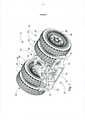
[023] Figura 1 mostra uma vista traseira axonométrica do aparelho de transporte em concordância com a presente invenção;[023] Figure 1 shows an axonometric rear view of the transport apparatus in accordance with the present invention;
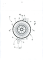
[024] Figura 2 mostra uma vista dianteira do aparelho de transporte em concordância com a presente invenção;[024] Figure 2 shows a front view of the transport apparatus in accordance with the present invention;
[025] Figura 3 mostra uma vista traseira do aparelho de transporte em concordância com a presente invenção;[025] Figure 3 shows a rear view of the transport apparatus in accordance with the present invention;
[026] Figura 4 mostra uma vista dianteira axonométrica do aparelho de transporte em concordância com a presente invenção;[026] Figure 4 shows an axonometric front view of the transport apparatus in accordance with the present invention;
[027] Figura 5 mostra uma vista lateral do aparelho de transporte em concordância com a presente invenção;[027] Figure 5 shows a side view of the transport apparatus in accordance with the present invention;
[028] Figura 6 mostra uma seção transversal do aparelho de transporte em concordância com a presente invenção, correndo verticalmente através do aparelho e longitudinalmente através do eixo de rodas;[028] Figure 6 shows a cross section of the transport apparatus in accordance with the present invention, running vertically through the apparatus and longitudinally through the wheel axle;
[029] Figura 7 mostra uma seção transversal do aparelho de transporte em concordância com a presente invenção, correndo horizontalmente através do aparelho e longitudinalmente através do eixo de rodas;[029] Figure 7 shows a cross section of the transport apparatus in accordance with the present invention, running horizontally through the apparatus and longitudinally through the wheel axle;
[030] Figura 8 mostra uma vista de fundo do aparelho de transporte em concordância com a presente invenção;[030] Figure 8 shows a bottom view of the transport apparatus in accordance with the present invention;
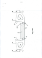
[031] Figura9a mostra uma vista lateral esquemática do aparelho de transporte em concordância com a presente invenção, quando transportando um carregador;[031] Figure 9a shows a schematic side view of the transport apparatus in accordance with the present invention, when carrying a loader;
[032] Figura9b mostra uma vista traseira esquemática do aparelho de transporte em concordância com a presente invenção, quando transportando um carregador;[032] Figure 9b shows a schematic rear view of the transport apparatus in accordance with the present invention, when carrying a loader;
[033]FiguralOa mostra o chassi do aparelho de transporte em concordância com a presente invenção em uma seção transversal parcial, sem as segundas partes laterais e as rodas observadas a partir de trás;[033]Figure 10a shows the chassis of the transport apparatus in accordance with the present invention in a partial cross section, without the second sides and wheels seen from the rear;
[034]FiguralOb mostra uma vista detalhada da junção aparafusada da Figura 10a; e[034]Figure 10b shows a detailed view of the bolted joint of Figure 10a; and
[035] Figura 11 mostra a construção de uma roda do aparelho de transporte em concordância com a presente invenção em maiores detalhes.[035] Figure 11 shows the construction of a wheel of the transport apparatus in accordance with the present invention in greater detail.
[036] Os Desenhos das Figuras acompanhantes são somente representações esquemáticas / diagramáticas e a presente invenção não está limitada para as concretizações neles representadas.[036] The accompanying Figure Drawings are only schematic / diagrammatic representations and the present invention is not limited to the embodiments represented therein.
[037] As Figuras 1-8 mostram uma concretização preferida do aparelho de transporte em concordância com a presente invenção. A Figura 9a e a Figura 9b mostram ilustrações esquemáticas da utilização do aparelho de transporte quando transportando um carregador. O aparelho de transporte (10) das Figuras 1-8 inclui um chassi (12), rodas (22), e um espaço de carga (21) para transportamento de um objeto (100) (na Figura 9a e na Figura 9b) . O chassi (12) do aparelho de transporte (10) é formado de uma parte traseira assemelhada à placa (14'), uma parte dianteira (14) (na Figura 2) , partes laterais (16), uma parte de plataforma (20) entre as partes laterais (16), e as segundas partes laterais (18). Aqui posteriormente, a expressão partes laterais internas (16) irá ser utilizada para as partes laterais (16) e a expressão partes laterais externas (18) para as segundas partes laterais (18).[037] Figures 1-8 show a preferred embodiment of the transport apparatus in accordance with the present invention. Figure 9a and Figure 9b show schematic illustrations of the use of the transport apparatus when transporting a loader. The transport apparatus (10) of Figures 1-8 includes a chassis (12), wheels (22), and a cargo space (21) for transporting an object (100) (in Figure 9a and Figure 9b). The chassis (12) of the transport apparatus (10) is formed of a plate-like rear part (14'), a front part (14) (in Figure 2), side parts (16), a platform part (20 ) between the sides (16), and the second sides (18). Here later, the expression inner sides (16) will be used for the sides (16) and the expression outer sides (18) for the second sides (18).
[038] As partes do chassi (12) formam, no plano horizontal, uma estrutura fechada (27), no interior da qual estão preferivelmente as rodas internas (23) e o espaço de carga (21) . Na estrutura fechada (27) , um espaço que se encaixa (ajusta) em uma ou mais rodas (24) é formado entre a parte lateral interna (16), e a parte lateral externa (18), a parte dianteira (14), e a parte traseira (14'). O espaço de carga (21) é formado entre as partes laterais internas (16), a parte dianteira (14) , e a parte traseira (14'), e bem como sobre o topo da parte de plataforma (20). As rodas (22) são, em concordância com uma concretização da presente invenção, montadas sobre eixos de rodas sobre as partes laterais externas (18) e eixos de rodas (26) correndo através delas, e a partir das extremidades dos eixos de rodas (26) para as partes laterais internas (16). Se desviando a partir das Figuras, o aparelho de transporte em concordância com a presente invenção pode também ser implementado de uma maneira tal que existe somente uma roda sobre cada lateral do espaço de carga (21). Caso em que, a roda tem que ser de uma grande largura, de maneira a conseguir uma suficiente capacidade de carregamento de carga.[038] The parts of the chassis (12) form, in the horizontal plane, a closed structure (27), inside which are preferably the internal wheels (23) and the cargo space (21). In the closed structure (27) , a space that fits (fits) on one or more wheels (24) is formed between the inner side (16), and the outer side (18), the front (14), and the back (14'). The cargo space (21) is formed between the inner side parts (16), the front part (14), and the rear part (14'), and as well as over the top of the platform part (20). The wheels (22) are, in accordance with an embodiment of the present invention, mounted on wheel axles on the outer sides (18) and wheel axles (26) running therethrough, and from the ends of the wheel axles ( 26) for the inner sides (16). Departing from the Figures, the transport apparatus in accordance with the present invention can also be implemented in such a way that there is only one wheel on each side of the cargo space (21). In which case, the wheel has to be of a large width in order to achieve a sufficient load carrying capacity.
[039] Aqui posteriormente, a expressão espaço de esteira (21') irá ser utilizada para o espaço de carga (21) , devido para o fato de que nas concretizações exemplificativas da presente invenção em concordância com as Figuras, o objeto a ser transportado é um carregador equipado com esteiras. Similarmente, a expressão carregador (100') irá ser utilizada aqui posteriormente para o objeto (100) a ser transportado.[039] Here later, the expression mat space (21') will be used for the cargo space (21) , due to the fact that in the exemplary embodiments of the present invention in accordance with the Figures, the object to be transported it is a loader equipped with tracks. Similarly, the expression carrier (100') will be used here later for the object (100) to be transported.
[040] Em concordância com a Figura 2 e com a Figura 3, cada roda (22) é preferivelmente montada em mancais (suportes) unicamente sobre o intervalo de eixo de rodas suportado (25) (na Figura 6) do eixo de rodas (26) . Em conexão com isto, a expressão intervalo de eixo de rodas se refere para a parte do eixo de rodas exterior ao ponto ou pontos de suporte. Por consequência, a estrutura do eixo de rodas (26) e seu suporte podem ser razoavelmente leves, devido para o fato de que as forças são transmitidas para o ponto ou pontos de suporte (62) do eixo de rodas (26) no chassi (12). Os pontos de suporte (62) são mostrados em maiores detalhes na Figura 6 e na Figura 7. Devido para o fato de que as rodas (22) são montadas em mancais sobre o eixo de rodas (26) próximas para o ponto de suporte (26) do eixo de rodas (26) nas partes laterais (16) e (18) , o momento de torsão transmitido para o eixo de rodas (26) através das rodas (22) permanece razoavelmente pequeno. Cada eixo de rodas (26) é preferivelmente suportado sobre o chassi (12) a partir de pelo menos dois pontos de suporte (62) .[040] In accordance with Figure 2 and Figure 3, each wheel (22) is preferably mounted on bearings (supports) solely on the range of supported wheel axle (25) (in Figure 6) of the wheel axle ( 26) . In connection with this, the term wheel axle range refers to the part of the wheel axle outside the support point or points. Consequently, the wheel axle frame (26) and its support can be reasonably light due to the fact that forces are transmitted to the support point or points (62) of the wheel axle (26) on the chassis ( 12). The support points (62) are shown in greater detail in Figure 6 and Figure 7. Due to the fact that the wheels (22) are mounted in bearings on the axle of wheels (26) close to the support point ( 26) of the wheel axle (26) at the sides (16) and (18), the torque transmitted to the wheel axle (26) through the wheels (22) remains reasonably small. Each wheel axle (26) is preferably supported on the chassis (12) from at least two support points (62).
[041] Na concretização das Figuras da presente invenção, o eixo de rodas unificado (26) corre através da parte lateral externa (18), tão distante quanto para a parte lateral interna (16). 0 eixo de rodas (26) é suportado na parte lateral interna (16) com o auxilio de uma superfície esférica (54), que é mostrada na Figura 6 e na Figura 7. Durante transportamento, o peso do carregador é transmitido através das esteiras do carregador para o espaço de esteira (21') e a partir de lá através da parte traseira (14' ) e da parte dianteira (14) primordialmente para a parte lateral externa (18). A partir da parte lateral externa (18) o peso é transmitido para o eixo de rodas (26) e, então, para as rodas (22). Em outras palavras, a parte lateral externa (18) transmite a maior parte das forças para o eixo de rodas (26) enquanto a tarefa da parte lateral interna (16) é a de transmitir o momento por intermédio da superfície esférica (54) segurando (suportando) o eixo de rodas (26) em linha reta. A superfície esférica (54) transmite a força para a parte lateral interna (16) com o auxilio de um colar (56) , independentemente de possível torsão que pode aparecer enquanto se movimentando. A utilização de uma superfície esférica (54) permite que o eixo de rodas (26) venha a flexionar no ponto correto. Em adição, a superfície esférica (54) facilita o dimensionamento do aparelho de transporte (10) . O eixo de rodas (26) é fixado na parte lateral externa (18) no ponto de suporte (62). A solução de atamento do eixo de rodas (26) é preferivelmente similar sobre ambas as laterais do aparelho de transporte (10).[041] In the embodiment of the Figures of the present invention, the unified wheel axle (26) runs through the outer side (18), as far as to the inner side (16). The wheel axle (26) is supported on the inner side (16) with the aid of a spherical surface (54), which is shown in Figure 6 and Figure 7. During transport, the weight of the loader is transmitted through the conveyors. from the loader to the mat space (21') and from there through the rear (14') and the front (14) primarily to the outer side (18). From the outer side (18) the weight is transmitted to the wheel axle (26) and then to the wheels (22). In other words, the outer side (18) transmits most of the forces to the wheel axle (26) while the task of the inner side (16) is to transmit the moment via the spherical surface (54) holding (supporting) the wheel axle (26) in a straight line. The spherical surface (54) transmits the force to the inner side (16) with the aid of a collar (56), regardless of possible torsion that may appear while moving. The use of a spherical surface (54) allows the wheel axle (26) to flex at the correct point. In addition, the spherical surface (54) facilitates the dimensioning of the transport apparatus (10). The wheel axle (26) is fixed on the outer side (18) at the support point (62). The wheel axle tying solution (26) is preferably similar on both sides of the transport apparatus (10).
[042] Em concordância com a Figura 4, as partes assemelhadas á placa do chassi (12) podem ser feitas mais leves, por exemplo, com o auxilio de cavidades de alivio de peso (34) . Isto irá trazer a vantagem de redução do peso total do aparelho de transporte. As partes do chassi (12) são preferivelmente atadas umas para as outras com o auxilio de junções aparafusadas (44), de maneira que o aparelho de transporte (10) irá ser mais fácil de manufaturar. Em adição, as junções aparafusadas (44) irão ser fáceis para abrir se requerido for. As partes laterais externas (18) podem ser atadas para a parte traseira (14') e a parte dianteira (14) com o auxilio de junções aparafusadas verticais (36) (mostradas na Figura 2). Por consequência, as partes laterais externas (18) podem ser facilmente destacadas, por exemplo, quando de troca de um pneu. Os parafusos (36) podem, então, ser abertos, a parte lateral externa (18) destacada, e as rodas gêmeas elevadas do eixo de rodas (26) .[042] In accordance with Figure 4, the parts similar to the chassis plate (12) can be made lighter, for example, with the aid of weight relief cavities (34) . This will bring the advantage of reducing the overall weight of the transport device. The chassis parts (12) are preferably tied together with the aid of bolted joints (44), so that the transport apparatus (10) will be easier to manufacture. In addition, the bolted joints (44) will be easy to open if required. The outer sides (18) can be tied to the rear (14') and the front (14) with the aid of vertical bolted joints (36) (shown in Figure 2). Consequently, the outer sides (18) can be easily detached, for example, when changing a tyre. The screws (36) can then be opened, the outer side (18) detached, and the twin wheels raised from the wheel axle (26) .
[043] Um ponto importante quando utilizando junções aparafusadas é o de que existem preferivelmente recursos de junção de interbloqueio (74) entre pelo menos a parte de plataforma (20) e as partes laterais (16) . Existem preferivelmente também recursos de junção de interbloqueio entre a parte de plataforma (20) e a parte dianteira (14) . A Figura 10b mostra uma imagem esquemática dos recursos de junção de interbloqueio (74). A lingüeta macho (72) dos recursos de junção de interbloqueio pode ser formada na parte de plataforma (20), enquanto as ranhuras fêmeas (70) podem ser formadas nas partes laterais (16) e na parte dianteira (14). A lingüeta macho (72) e a ranhura fêmea (70) podem também ser de outra forma do que arredondada. 0 interbloqueio torna possivel aumentar consideravelmente a área de superfície de suporte de carga horizontal entre as partes, que transporta uma grande porção da carga. Isto permite que as junções entre as partes venham a ser implementadas como junções aparafusadas, na medida em que, então, os parafusos unicamente reforçam a junção e seguram (suportam) as partes juntamente horizontalmente, enquanto que retenção vertical acontece primordialmente com o auxilio dos recursos de junção de interbloqueio. Sem os recursos de junção de interbloqueio, o número de parafusos requeridos deveria ser tão grande que a parte de plataforma (20) deveria ter que ser feita mais espessa, de maneira a criar uma área de superfície suficientemente grande para os parafusos. Em conexão com isto, deveria ser compreendido que a expressão recursos de junção de interbloqueio se refere mais genericamente para várias espécies de junções de lingüeta e ranhura, junções rebatidas, junções de rebaixo, e junções encravadas (em cunha), e bem como diferentes variações das mesmas. Por exemplo, ranhuras podem ser usinadas em ambas as peças a serem atadas, entre as quais uma cunha formando a peça macho é inserida.[043] An important point when using bolted joints is that there are preferably interlocking joint resources (74) between at least the platform part (20) and the side parts (16). There are preferably also interlocking joint features between the platform part (20) and the front part (14). Figure 10b shows a schematic image of the interlock junction features (74). The male tongue (72) of the interlocking joint features can be formed in the platform part (20), while the female grooves (70) can be formed in the sides (16) and in the front part (14). The male tongue (72) and the female groove (70) may also be of other shape than rounded. The interlocking makes it possible to considerably increase the horizontal load-bearing surface area between the parts, which carry a large portion of the load. This allows the joints between the parts to be implemented as bolted joints, as the screws then only reinforce the joint and hold (support) the parts together horizontally, while vertical retention occurs primarily with the aid of resources interlock junction. Without the interlocking joint features, the number of screws required would be so large that the platform part (20) would have to be made thicker in order to create a sufficiently large surface area for the screws. In connection with this, it should be understood that the term interlocking joint features refers more generally to various kinds of tongue-and-groove joints, recessed joints, recessed joints, and wedged joints, as well as different variations the same. For example, slots can be machined in both parts to be knotted, between which a wedge forming the male part is inserted.
[044] Em concordância com a Figura 5, o comprimento da parte de plataforma (21') entre a parte traseira (14') e a parte dianteira (14) deveria ser tal que o eixo de rodas da roda rotacionando a esteira do carregador irá tomar uma posição relativamente para os eixos de rodas (26) do aparelho de transporte (10) que está mais próximo para a parte traseira (14') do aparelho de transporte (10) do que para a parte dianteira (14) . 0 peso do carregador irá, então, ser seguramente retido no aparelho de transporte (10). Em adição, o comprimento do espaço de esteira (21') é também determinado pelo diâmetro das rodas (22), na medida em que deveria existir espaço para as rodas internas entre a parte dianteira (14) e a parte traseira (14' ) . 0 espaço de esteira (21') deveria ser suficientemente amplo lateralmente para a esteira do carregador para se encaixar (ajustar) no interior dele na direção de largura. A largura do espaço de esteira (21') deveria ser 800 mm - 2.000 mm. A parte traseira (14') pode incluir batentes verticais (46) para a movimentação longitudinal das esteiras, contra os quais as esteiras do carregador estão correndo. Em adição, o aparelho de transporte (10) pode incluir um circuito (loop) de içamento (32), que é utilizado quando de manipulação do aparelho de transporte (10) com um carregador.[044] In accordance with Figure 5, the length of the platform part (21') between the rear (14') and the front (14) should be such that the wheel axle rotating the loader track will take a position relative to the wheel axles (26) of the transport apparatus (10) which is closer to the rear (14') of the transport apparatus (10) than to the front (14). The weight of the magazine will then be securely retained in the transport apparatus (10). In addition, the length of the mat space (21') is also determined by the diameter of the wheels (22), as there should be space for the inner wheels between the front (14) and the rear (14') . The mat space (21') should be wide enough laterally for the loader mat to fit (adjust) inside it in the width direction. The width of the mat space (21') should be 800mm - 2000mm. The rear (14') may include vertical stops (46) for the longitudinal movement of the tracks, against which the loader tracks are running. In addition, the transport apparatus (10) may include a hoist loop (32) which is used when handling the transport apparatus (10) with a loader.
[045] A Figura 6 mostra uma seção transversal ao longo da linha A - A na Figura 5. Existem preferivelmente pelo menos duas rodas (22) sobre cada lateral do aparelho de transporte, de maneira que capacidade de suporte de carga adicional é obtida. Podem existir mais rodas, caso no qual irá existir uma parte lateral entre cada roda, sobre a qual o eixo de rodas é suportado. 0 pneu (24) de cada roda (22) é instalado sobre um aro (28) , aro (28) que pode, por sua parte, ser permanentemente atado para o cubo de roda (52) da roda (22) . A Figura 6 mostra como os aros (28) são montados em mancais (suportes) com o auxilio de mancais (suportes) (50) sobre o eixo de rodas fixado (26) pelos cubos de roda (52) . Em concordância com a Figura 6 e com a Figura 7, cada roda (22) é montada separadamente sobre mancais sobre o eixo de rodas (26) , que por sua vez é permanentemente atado no ponto de suporte (62) da placa lateral externa (18) . A montagem de mancai (rolamento, suporte) individual das rodas permite uma velocidade de rotação variável nas rodas, o que irá aperfeiçoar a habilidade de direção do aparelho de transporte nas curvas e reduzir a tensão (esforço) sobre o eixo de rodas.[045] Figure 6 shows a cross section along line A - A in Figure 5. There are preferably at least two wheels (22) on each side of the transport apparatus, so that additional load-bearing capacity is obtained. There may be more wheels, in which case there will be a side part between each wheel, on which the wheel axle is supported. The tire (24) of each wheel (22) is installed on a rim (28), rim (28) which can, in turn, be permanently attached to the wheel hub (52) of the wheel (22). Figure 6 shows how the rims (28) are mounted on bearings (supports) with the aid of bearings (supports) (50) on the wheel axle fixed (26) by the wheel hubs (52). In accordance with Figure 6 and Figure 7, each wheel (22) is mounted separately on bearings on the wheel axle (26) , which in turn is permanently attached to the support point (62) of the outer side plate ( 18) . The individual bearing (bearing, support) assembly of the wheels allows for a variable rotation speed on the wheels, which will improve the conveyor's ability to steer through curves and reduce the tension (strain) on the wheel axle.
[046] A Figura 7 mostra uma seção transversal dos pontos da Figura 5 sobre a linha B - B. Em concordância com a Figura 1, com a Figura 2 e com a Figura 7, o fundo do espaço de esteira (21') preferivelmente inclui trilhos (bandas de rodagem) não deslizantes (30). Os trilhos não deslizantes (30) podem ser formados de sulcos (arestas) (40) em concordância com as Figuras. Os sulcos irão repousar entre os sulcos das esteiras e, por consequência, prevenir que o aparelho de transporte venha a deslizamento (derrapagem) a partir de debaixo da esteira. Alternativamente, o trilho não deslizante (30) pode consistir de uma placa, na qual existem recessos, que são agarrados pelas saliências (projeções) da esteira do carregador.[046] Figure 7 shows a cross section of the points in Figure 5 on the line B - B. In accordance with Figure 1, Figure 2 and Figure 7, the mat space bottom (21') preferably includes non-sliding rails (treads) (30). The non-sliding rails (30) may be formed from grooves (edges) (40) in accordance with the Figures. The grooves will rest between the grooves of the mats and therefore prevent the conveyor apparatus from slipping (skid) from under the mat. Alternatively, the non-sliding rail (30) may consist of a plate, in which there are recesses, which are gripped by the protrusions (projections) of the conveyor belt.
[047] A Figura 8 mostra o aparelho de transporte (10) observado a partir de debaixo. Em concordância com a Figura 8, o espaço de esteira (21' ) está entre as rodas (22) . 0 espaço de esteira (21') está no centro relativamente para os eixos de rodas (26) , de maneira que o peso do carregador sendo transportado irá ser distribuído relativamente igualmente sobre ambos os eixos de rodas (26) . O carregamento do carregador em cima do aparelho de transporte (10) acontece pela parte dianteira (14) do chassi (12) do aparelho de transporte (10) repousando contra o solo, quando o carregador é revertido para o espaço de esteira (21'), até que a esteira do carregador vem a esbarrar contra a parte traseira (14') do chassi (12) . Depois disto, o aparelho de transporte (10) pode ser segurado para as esteiras do carregador com o auxilio de saliências (alças) (46) (mostradas na Figura 1 e na Figura 2). Ao mesmo tempo, os trilhos não deslizantes (30) previnem que o aparelho de transporte venha a deslizar a partir de debaixo das esteiras do carregador.[047] Figure 8 shows the transport apparatus (10) seen from below. In accordance with Figure 8, the mat space (21') is between the wheels (22). The mat space (21') is at the center relative to the wheel axles (26) so that the weight of the loader being transported will be distributed relatively evenly over both the wheel axles (26). The loading of the loader on top of the transport apparatus (10) takes place through the front (14) of the chassis (12) of the transport apparatus (10) resting against the ground, when the loader is reverted to the mat space (21' ), until the loader mat comes into contact with the rear (14') of the chassis (12) . Thereafter, the transport apparatus (10) can be secured to the conveyor belts with the aid of lugs (handles) (46) (shown in Figure 1 and Figure 2). At the same time, the non-sliding rails (30) prevent the transport apparatus from slipping from under the loader tracks.
[048] 0 transportamento de um carregador por intermédio do aparelho de transporte em concordância com a presente invenção pode ser implementado em concordância com as imagens esquemáticas da Figura 9a e da Figura 9b. Na situação inicial, o carregador ou máquina de trabalho similar é tracionado/a de modo suficiente em cima de um aparelho de transporte ou de dois aparelhos de transporte em que a esteira do carregador atinge a parte traseira do aparelho de transporte. 0 aparelho de transporte em concordância com a presente invenção é preferivelmente utilizado de uma maneira tal que existe um aparelho de transporte para cada uma das esteiras do carregador. Quando as esteiras estão rotacionando, os trilhos não deslizantes agarram as esteiras e o carregador é, então, prevenido de vir a se movimentar no espaço de esteira do aparelho de transporte. Em adição a isto, o carregador pode ser bloqueado por intermédio de várias espécies de recursos de bloqueio.[048] The transport of a loader through the transport apparatus in accordance with the present invention can be implemented in accordance with the schematic images of Figure 9a and Figure 9b. In the initial situation, the loader or similar working machine is sufficiently towed on top of a transport apparatus or two transport apparatus in which the loader belt reaches the rear of the transport apparatus. The transport apparatus in accordance with the present invention is preferably used in such a way that there is a transport apparatus for each of the conveyor belts. When the tracks are rotating, the non-skid rails grip the tracks and the loader is then prevented from moving into the conveyor's track space. In addition to this, the loader can be blocked through various kinds of blocking resources.
[049] Depois disto, a lança (longarina) de trabalho (104) do carregador (100') é rotacionada descendentemente relativamente para o eixo de rodas horizontal em cima da plataforma (108) do dispositivo de reboque (102), por exemplo, um caminhão de lixo, até que as esteiras (106) do carregador (100' ) venham a se elevar do solo para a situação em concordância com a Figura 9a e com a Figura 9b. 0 peso do carregador irá, então, repousar do aparelho de transporte em concordância com a presente invenção e da plataforma do dispositivo de reboque. A distribuição do peso entre a plataforma do dispositivo de reboque e o aparelho de transporte irá depender da estrutura do carregador. Depois disto, o carregador irá estar pronto para transportamento.[049] After this, the working boom (104) of the loader (100') is rotated downwardly relative to the horizontal wheel axle on top of the platform (108) of the towing device (102), e.g. a garbage truck, until the conveyor tracks (106) of the loader (100' ) come to rise from the ground to the situation in accordance with Figure 9a and Figure 9b. The weight of the loader will then rest on the transport apparatus in accordance with the present invention and the platform of the towing device. The weight distribution between the towing device platform and the transport device will depend on the loader structure. After that, the charger will be ready for transport.
[050] Em concordância com uma concretização da presente invenção, o aparelho de transporte é adequado para utilização para transportamento de grandes objetos pesando mais do que 100 toneladas, preferivelmente mais do que 400 toneladas. 0 aparelho de transporte é particularmente intencionado para transportamento de carregadores com uma subestrutura de esteira, particularmente de escavadeiras. A máquina de trabalho a ser transportada pode ser qualquer máquina de trabalho não importando se com uma subestrutura de esteira, que é equipada com um dispositivo de escavação, ou algum outro elemento de elevação. Por intermédio do aparelho de transporte em concordância com a presente invenção, é possivel transportar um carregador pesando mais do que 400 toneladas sem a largura global do aparelho de transporte aumentando consideravelmente. Dois aparelhos de transporte em concordância com a presente invenção são preferivelmente utilizados para transportar um carregador, quando deveria existir um aparelho de transporte para cada esteira. Os aparelhos de transporte são, então, preferivelmente aparelhos de transporte que são separados um a partir do outro, e em que o carregador sendo transportado em si mesmo se conecta um para o outro. Alternativamente, os aparelhos de transporte podem ser conectados um para o outro com o auxilio de um elemento intermediário, para formar uma totalidade única.[050] In accordance with an embodiment of the present invention, the transport apparatus is suitable for use for transporting large objects weighing more than 100 tons, preferably more than 400 tons. The transport apparatus is particularly intended for transporting loaders with a mat substructure, particularly excavators. The working machine to be transported can be any working machine regardless of whether it has a crawler sub-frame, which is equipped with an excavating device, or some other lifting element. By means of the transport apparatus in accordance with the present invention, it is possible to transport a loader weighing more than 400 tons without the overall width of the transport apparatus increasing considerably. Two transport apparatus in accordance with the present invention are preferably used to transport a loader, when there should be a transport apparatus for each mat. The transport apparatus are then preferably transport apparatus which are separated from one another, and in which the charger being transported itself connects to one another. Alternatively, the transport devices can be connected to one another with the aid of an intermediate element, to form a single whole.
[051] A construção de eixo de rodas do aparelho de transporte em concordância com a presente invenção possibilita que o atamento das rodas para o eixo de rodas venha a ser compacto e consideravelmente mais leve do que as soluções do estado da técnica. Por consequência, a distância entre a roda externa e a parte lateral interna pode ser mantida pequena até mesmo em aparelhos de transporte intencionados para grandes carregadores, por consequência, permitindo um espaço de esteira mais amplo. A construção do aparelho de transporte é também simplificada pelo fato de que o aro e cubo de roda das rodas são combinados para formar um componente único, que é fácil para manufaturar. Em adição, a construção pode ser simplificada por feitura das junções entre os componentes do chassi como junções aparafusadas.[051] The construction of the wheel axle of the transport apparatus in accordance with the present invention enables the tying of the wheels to the wheel axle to be compact and considerably lighter than the prior art solutions. As a result, the distance between the outer wheel and the inner side can be kept small even in transport devices intended for large loaders, thereby allowing a wider track space. The construction of the transport apparatus is also simplified by the fact that the rim and wheel hub of the wheels are combined to form a single component, which is easy to manufacture. In addition, the construction can be simplified by making the joints between the chassis components as bolted joints.
[052] 0 aparelho de transporte em concordância com a presente invenção pode ser equipado com freios de estacionamento (60) (mostrados na Figura 2), que bloqueiam imediatamente e automaticamente uma vez que o carregador seja desconectado (desligado) do aparelho de transporte. 0 aparelho de transporte pode também incluir freios para utilização enquanto funcionado (rodando), que podem restringir a movimentação do carregador, por exemplo, quando indo descida abaixo. Se necessário for, a velocidade do carregador durante transportamento pode ser freada por elevação da lança (longarina) de trabalho, quando a esteira do carregador irá fazer ligeiro contato com o solo.[052] The transport apparatus in accordance with the present invention may be equipped with parking brakes (60) (shown in Figure 2), which lock immediately and automatically once the charger is disconnected (switched off) from the transport apparatus. The transport apparatus may also include brakes for use while operating (running), which may restrict movement of the loader, for example, when going downhill. If necessary, the loader speed during transport can be braked by lifting the working boom (spar), when the loader track will make light contact with the ground.
[053] A Figura 9a mostra uma vista traseira do chassi (12) do carro de transporte em concordância com a presente invenção, mostrado sem rodas e partes laterais externas. Na Figura 9a, o chassi (12) é seccionado (cortado), de maneira que a placa traseira não é visivel. Em concordância com a Figura 9a, as partes laterais internas (16) do chassi (12) são preferivelmente atadas para a parte de plataforma (20) entre as mesmas com o auxilio de uma junção aparafusada (44) . A junção aparafusada (44) é mostrada na área marcada com a marcação "det A". A imagem de detalhe "det A" é mostrada em maiores detalhes na Figura 10b. A junção aparafusada (44) é formada a partir de diversos parafusos (80) em paralelo, que atam a parte de plataforma (20) e a parte lateral interna (16) uma para a outra. Abaixo da parte de plataforma (20) existe preferivelmente uma segunda parte de plataforma (29), que reforça a estrutura. A segunda parte de plataforma (29) é também atada por uma junção aparafusada (44) para a parte lateral interna (16). A segunda parte de plataforma (29) pode cobrir somente parte da distância abaixo da parte de plataforma (20), ou em alguns casos, pode não ser requerida absolutamente.[053] Figure 9a shows a rear view of the chassis (12) of the transport car in accordance with the present invention, shown without wheels and external sides. In Figure 9a, the chassis (12) is sectioned (cut) so that the back plate is not visible. In accordance with Figure 9a, the inner sides (16) of the chassis (12) are preferably tied to the platform part (20) therebetween with the aid of a bolted joint (44). The bolted joint (44) is shown in the area marked "det A". The detail image "det A" is shown in greater detail in Figure 10b. The bolted joint (44) is formed from several bolts (80) in parallel, which tie the platform part (20) and the inner side (16) together. Below the platform part (20) there is preferably a second platform part (29), which reinforces the structure. The second platform part (29) is also tied by a bolted joint (44) to the inner side (16). The second platform part (29) may only cover part of the distance below the platform part (20), or in some cases, it may not be required at all.
[054] Quando transportando um objeto utilizando o aparelho de transporte em concordância com a presente invenção, o peso do objeto é transmitido através da parte de plataforma (20) para as partes laterais (16), e bem como para as partes dianteira e traseira (14) e (14'), e através das mesmas para as segundas partes laterais. Ainda que as partes laterais externas venham a transportar (carregar) a maior parte da carga, a junção aparafusada (44) também entre a parte de plataforma (20) e a parte lateral interna (16) deveria ter capacidade de transportar cargas consideráveis. De maneira a transportar a carga, recursos de junção de interbloqueio (74), que consistem de lingüetas machos (72) e ranhuras fêmeas (70), são preferivelmente formados em conexão com a junção aparafusada (44). Os parafusos (80) da junção aparafusada (44) preferivelmente correm através dos recursos de junção de interbloqueio (74), mais especificamente no centro da lingüeta macho (72) e da ranhura fêmea (70). Compressão máxima irá, então, ser criada próxima para as partes de suporte de carga, isto é, os recursos de junção de interbloqueio (74). Os parafusos (80) podem também estar acima e/ou abaixo dos recursos de junção de interbloqueio (74).[054] When transporting an object using the transport apparatus in accordance with the present invention, the weight of the object is transmitted through the platform part (20) to the sides (16), as well as to the front and rear parts. (14) and (14'), and through them to the second side parts. Although the outer sides will carry (carry) most of the load, the bolted joint (44) also between the platform part (20) and the inner side (16) should be capable of carrying considerable loads. In order to carry the load, interlocking joint features (74), which consist of male tongues (72) and female grooves (70), are preferably formed in connection with the bolted joint (44). The bolts (80) of the bolted joint (44) preferably run through the interlocking joint features (74), more specifically in the center of the male tongue (72) and the female groove (70). Maximum compression will then be created close to the load-bearing parts, i.e. the interlocking join features (74). The screws (80) may also be above and/or below the interlocking joint features (74).
[055] 0 propósito dos recursos de junção de interbloqueio (74) é o de aumentar a área de superfície perpendicular para os parafusos, que transmitem as forças verticais a partir da parte de plataforma (20) para as partes laterais (16). Com o auxilio dos recursos de junção de interbloqueio (74), a área de superfície transmitindo a força vertical aumenta em muitas vezes, comparada com a utilização de parafusos unicamente. Por consequência, os parafusos utilizados podem ser mais leves em estrutura e, por consequência, requerem perfurações rebaixadas (76) na parte de plataforma (20) . Filamentos (fios, roscas) rebaixados para as roscas dos parafusos são preferivelmente feitos na parte de plataforma (20). A tarefa dos parafusos na junção aparafusada (44) permanece primordialmente a de transmitir forças paralelas para a parte de plataforma (20) . Recursos de junção de interbloqueio (74) podem ser dispostos pelo menos na parte de plataforma (20) e nas partes laterais (16) , mas preferivelmente também na parte traseira (14') e na parte dianteira (14).[055] The purpose of the interlocking joint features (74) is to increase the perpendicular surface area for the screws, which transmit the vertical forces from the platform part (20) to the sides (16). With the aid of the interlocking joint features (74), the surface area transmitting the vertical force is increased by many times compared to using screws alone. Consequently, the screws used can be lighter in structure and therefore require undercut perforations (76) in the platform part (20). Filaments (threads, threads) recessed into the screw threads are preferably made in the platform part (20). The task of the screws in the bolted joint (44) remains primarily that of transmitting parallel forces to the platform part (20). Interlocking joint features (74) can be arranged at least on the platform part (20) and on the sides (16), but preferably also on the rear (14') and on the front (14).
[056] A segunda parte de plataforma (29) pode ser atada com o auxilio de parafusos (78) , sem recursos de junção de interbloqueio. Perfurações (82), que incluem alargamentos (84) para as cabeças dos parafusos (78) e (80) , são preferivelmente feitas através das partes laterais (16). Isto protege as cabeças de parafusos a partir de impactos.[056] The second platform part (29) can be fastened with the aid of screws (78), without interlocking joint features. Perforations (82), which include flares (84) for the heads of screws (78) and (80), are preferably made through the sides (16). This protects the screw heads from impacts.
[057] 0 aparelho de transporte em concordância com a presente invenção pode ser manufaturado a partir, por exemplo, de aço com uma alta resistência, ou de um material similar, que irá suportar as (resistir às) tensões impostas (esforços impostos) sobre o aparelho de transporte. 0 tipo (qualidade) de aço utilizado deveria preferivelmente ser o assim chamado aço de dupla resistência, caso em que os componentes de chassi a serem manufaturados podem ser feitos com metade tão espessa quanto quando os mesmos são feitos a partir de aço normal. Em conexão com isto, a expressão dupla resistência se refere a um tipo (qualidade) de aço, com uma resistência final (força máxima) de mais do que 500 MPa, preferivelmente de 600 MPa - 1.200 Mpa.[057] The transport apparatus in accordance with the present invention may be manufactured from, for example, steel with a high strength, or a similar material, which will withstand the (resist the) stresses imposed (imposed stresses) on the transport apparatus. The type (quality) of steel used should preferably be so-called double strength steel, in which case the chassis components to be manufactured can be made half as thick as when they are made from normal steel. In connection with this, the term double strength refers to a type (quality) of steel, with an ultimate strength (maximum strength) of more than 500 MPa, preferably 600 MPa - 1,200 MPa.
[058] Em concordância com uma concretização da presente invenção, as rodas do aparelho de transporte podem ser suportadas sobre o chassi de uma assim chamada maneira de flutuação. Isto significa que as duas rodas sobre ambas as laterais do espaço de esteira são suportados com o auxilio de um eixo de rodas individual somente sobre a parte lateral externa. As partes laterais externas são, então, suportadas com o auxilio de uma superficie esférica, sobre a parte dianteira e a parte traseira do chassi, superficie esférica que permite que o eixo de rodas venha a se inclinar na direção transversal do aparelho de transporte. Isto possibilita que ambas as rodas venham a se mais bem adaptar para as formas de superficie da base e a pressão de superficie permanece igual entre as rodas. A aparência da solução pode corresponder aproximadamente para a concretização da presente invenção mostrada nas Figuras 1 - 9b.[058] In accordance with an embodiment of the present invention, the wheels of the transport apparatus can be supported on the chassis in a so-called floating manner. This means that the two wheels on both sides of the track space are supported with the aid of a single wheel axle on the outer side only. The outer sides are then supported with the aid of a spherical surface, on the front and rear of the chassis, a spherical surface that allows the wheel axle to lean in the transverse direction of the transport apparatus. This allows both wheels to better adapt to the base surface shapes and the surface pressure remains the same between the wheels. The appearance of the solution may roughly correspond to the embodiment of the present invention shown in Figures 1 - 9b.
[059] A combinação integrada de cubo de roda e aro pode também ser utilizada em aparelhos de transporte outros do que aqueles em concordância com as reivindicações de patente acompanhantes da presente invenção, em outras palavras, em qualquer aparelho de transporte não importando se intencionado para transportamento de objetos pesados. Mais especificamente, a combinação pode ser uma disposição como aquela da Figura 11 em conexão com a roda de um aparelho de transporte intencionado para o transportamento de objetos pesados, particularmente de máquinas de trabalho, tais como escavadeiras, se movimentando sobre esteiras, equipado com um dispositivo de escavadeira ou outro elemento de elevação, disposição na qual o aparelho de transporte inclui um chassi e rodas (22) atadas para o chassi com o auxilio de um eixo de rodas fixado, roda (22) cada uma da qual inclui um pneu (24) , um aro (28) para suporte do pneu (24) , e bem como um cubo de roda (52) para montagem do aro (28) em mancais (suportes) sobre um eixo de rodas (26). 0 aro (28) e o cubo de roda (52) são integrados para formar uma totalidade única, quando a construção irá ser consideravelmente mais simples do que em uma solução fundamentada sobre um cubo de roda e aro separados. Em outras palavras, recessos para os mancais (suportes) são usinados diretamente para o aro, de maneira que um cubo de roda separado não é requerido. Aqui, o pneu pode ser pressurizado por intermédio de um meio, ou pode ser um pneu de borracha sólida, um pneu de uretana, ou algum outro pneu "sólido" similar.[059] The integrated wheel hub and rim combination may also be used in transport apparatus other than those in accordance with the patent claims accompanying the present invention, in other words, in any transport apparatus no matter if intended for transporting heavy objects. More specifically, the combination may be an arrangement like that of Figure 11 in connection with the wheel of a transport apparatus intended for the transport of heavy objects, particularly of working machines, such as excavators, moving on tracks, equipped with a excavator device or other lifting element, arrangement in which the transport apparatus includes a chassis and wheels (22) fastened to the chassis with the aid of a fixed wheel axle, wheel (22) each of which includes a tire ( 24), a rim (28) for supporting the tire (24), as well as a wheel hub (52) for mounting the rim (28) on bearings (supports) on a wheel axle (26). The rim (28) and the wheel hub (52) are integrated to form a single whole, where construction will be considerably simpler than in a solution based on a separate wheel hub and rim. In other words, recesses for the bearings (brackets) are machined directly into the rim, so a separate wheel hub is not required. Here, the tire may be pressurized through a medium, or it may be a solid rubber tire, a urethane tire, or some other similar "solid" tire.
[060] Uma junção de interbloqueio entre componentes conectados por uma junção aparafusada pode também ser utilizada em aparelhos de transporte outros do que aqueles em concordância com as reivindicações de patente acompanhantes da presente invenção, em outras palavras, em qualquer aparelho de transporte não importando se intencionado para o transportamento de objetos pesados. Mais especificamente, a combinação pode ser uma disposição em conexão com o chassi de um aparelho de transporte intencionado para transportamento de objetos pesados, particularmente de máquinas de trabalho, tais como escavadeiras, se movimentando sobre esteiras, equipado com um dispositivo de escavadeira ou outro elemento de elevação, disposição na qual o chassi inclui pelo menos duas peças a serem atadas em ângulos essencialmente retos uma para a outra, que são dispostas para serem unidas uma para a outra com o auxilio de parafusos, em que pelo menos uma das peças inclui filamentos (fios, roscas) rebaixados para os parafusos. Na disposição, existem recursos de junção de interbloqueio entre as peças, que incluem uma lingüeta macho feita em uma peça e uma ranhura fêmea na outra peça. Com o auxilio dos recursos de interbloqueio, a área de superficie transmitindo força é aumentada em uma extensão muito maior do que por simplesmente adicionando mais junções aparafusadas.[060] An interlocking joint between components connected by a bolted joint may also be used in transport apparatus other than those in accordance with the patent claims accompanying the present invention, in other words, in any transport apparatus regardless of whether intended for the transport of heavy objects. More specifically, the combination may be an arrangement in connection with the chassis of a transport apparatus intended for transporting heavy objects, particularly working machines, such as excavators, moving on crawlers, equipped with an excavator device or other element lifting arrangement, arrangement in which the chassis includes at least two pieces to be fastened at essentially right angles to each other, which are arranged to be joined together with the aid of screws, at least one of the pieces including filaments. (wires, threads) recessed for screws. In the arrangement, there are interlocking joint features between the parts, which include a male tongue made in one part and a female groove in the other part. With the aid of the interlocking features, the surface area transmitting force is increased to a much greater extent than by simply adding more bolted joints.
[061] 0 aparelho de transporte em concordância com a presente invenção pode também ser utilizado para transportamento de objetos pesados outros do que máquinas de trabalho. Os objetos a serem transportados podem ser, por exemplo, partes de montagens parciais de navios, quando um aparelho de transporte ou mais aparelhos de transporte podem ser utilizados próximos uns para os outros ou em linha (alinhados). Tais objetos podem pesar milhares de toneladas. Os aparelhos de transporte podem suportar uns aos outros com o auxilio do objeto sendo transportado ou de um feixe intermediário separado.[061] The transport apparatus in accordance with the present invention can also be used for transporting heavy objects other than work machines. The objects to be transported can be, for example, parts of partial assemblies of ships, when one transport device or more transport devices can be used close to each other or in line (aligned). Such objects can weigh thousands of tons. The transport devices can support each other with the aid of the object being transported or a separate intermediate beam.
[062] Embora a presente invenção tenha sido descrita em concordância e com referência para concretizações exemplificativas especificas e preferidas, aqueles especializados no estado da técnica irão apreciar que a presente invenção pode ser concretizada de muitas outras diferentes formas com um número de modificações, variações e mudanças sendo conceptivel sem afastamento a partir do espirito inventivo e do escopo de proteção como estabelecido pelas reivindicações de patente acompanhantes.[062] Although the present invention has been described accordingly and with reference to specific and preferred exemplary embodiments, those skilled in the art will appreciate that the present invention may be embodied in many other different ways with a number of modifications, variations and changes being conceivable without departing from the inventive spirit and scope of protection as established by the accompanying patent claims.
Claims (13)
Applications Claiming Priority (1)
| Application Number | Priority Date | Filing Date | Title |
|---|---|---|---|
| FI20125214 | 2012-02-24 |
Publications (1)
| Publication Number | Publication Date |
|---|---|
| BR112014020854B1 true BR112014020854B1 (en) | 2021-11-16 |
Family
ID=
Similar Documents
| Publication | Publication Date | Title |
|---|---|---|
| US9663015B2 (en) | Transport apparatus for transporting heavy objects | |
| AU2014310492B2 (en) | Method and a transfer trailer for transferring a heavy transferable work machine | |
| RU2482992C2 (en) | Caterpillar track and forestry machine | |
| US7287947B2 (en) | Front loading trailer and method of use | |
| RU2765038C2 (en) | Support device in logging machine and logging machine | |
| US8414245B2 (en) | Container transfer system for uploading and downloading mating container relative to a transport vehicle | |
| US3000649A (en) | Couplings for sectional heavy duty apparatus | |
| BR112014020854B1 (en) | TRANSPORTATION APPLIANCE FOR TRANSPORTATION OF HEAVY OBJECTS | |
| CN107200073A (en) | Low flat bed semi trailer and its hitch structure, loading platform | |
| CN201494535U (en) | Land boat type transport machine | |
| US2649211A (en) | Horizontal boom swivel device for locomotive cranes | |
| CN215361326U (en) | Special transport vehicle for mine bridge type super-long rubber-tyred vehicle | |
| US1857784A (en) | Trailer | |
| US2091090A (en) | Transportation method and means | |
| RU24827U1 (en) | HEAVY Duty LOADED TRACK | |
| US2889060A (en) | Low bed trailer | |
| ITMN20000038A1 (en) | SNOW TRAILER | |
| PL66566Y1 (en) | Trailer, especially for a tractor | |
| BRMU8902958U2 (en) | automated motorcycle, quad and jet ski trailer |