BR112013008665B1 - Process for removing layers of workpieces - Google Patents
Process for removing layers of workpieces Download PDFInfo
- Publication number
- BR112013008665B1 BR112013008665B1 BR112013008665-3A BR112013008665A BR112013008665B1 BR 112013008665 B1 BR112013008665 B1 BR 112013008665B1 BR 112013008665 A BR112013008665 A BR 112013008665A BR 112013008665 B1 BR112013008665 B1 BR 112013008665B1
- Authority
- BR
- Brazil
- Prior art keywords
- voltage
- layer
- workpiece
- layers
- electrolyte
- Prior art date
Links
- 238000000034 method Methods 0.000 title claims abstract description 51
- 239000003792 electrolyte Substances 0.000 claims abstract description 24
- 238000000576 coating method Methods 0.000 claims description 13
- 230000001105 regulatory effect Effects 0.000 claims description 9
- 230000015572 biosynthetic process Effects 0.000 claims description 4
- 239000000758 substrate Substances 0.000 description 20
- 239000011248 coating agent Substances 0.000 description 11
- 230000007547 defect Effects 0.000 description 10
- 230000010287 polarization Effects 0.000 description 9
- 238000009434 installation Methods 0.000 description 4
- 229910000831 Steel Inorganic materials 0.000 description 3
- 229940043397 deconex Drugs 0.000 description 3
- 239000000463 material Substances 0.000 description 3
- 238000012163 sequencing technique Methods 0.000 description 3
- 239000010959 steel Substances 0.000 description 3
- QTBSBXVTEAMEQO-UHFFFAOYSA-N Acetic acid Chemical compound CC(O)=O QTBSBXVTEAMEQO-UHFFFAOYSA-N 0.000 description 2
- 230000007423 decrease Effects 0.000 description 2
- 238000010438 heat treatment Methods 0.000 description 2
- 239000011244 liquid electrolyte Substances 0.000 description 2
- 239000002184 metal Substances 0.000 description 2
- 239000012811 non-conductive material Substances 0.000 description 2
- 230000003647 oxidation Effects 0.000 description 2
- 238000007254 oxidation reaction Methods 0.000 description 2
- 239000000956 alloy Substances 0.000 description 1
- 229910045601 alloy Inorganic materials 0.000 description 1
- 230000000712 assembly Effects 0.000 description 1
- 238000000429 assembly Methods 0.000 description 1
- QVGXLLKOCUKJST-UHFFFAOYSA-N atomic oxygen Chemical compound [O] QVGXLLKOCUKJST-UHFFFAOYSA-N 0.000 description 1
- 230000033228 biological regulation Effects 0.000 description 1
- 238000006243 chemical reaction Methods 0.000 description 1
- 238000010276 construction Methods 0.000 description 1
- 238000001816 cooling Methods 0.000 description 1
- 230000007797 corrosion Effects 0.000 description 1
- 238000005260 corrosion Methods 0.000 description 1
- 238000004043 dyeing Methods 0.000 description 1
- 239000012799 electrically-conductive coating Substances 0.000 description 1
- 239000000696 magnetic material Substances 0.000 description 1
- 230000014759 maintenance of location Effects 0.000 description 1
- 238000003801 milling Methods 0.000 description 1
- 239000000203 mixture Substances 0.000 description 1
- 230000010355 oscillation Effects 0.000 description 1
- 229910052760 oxygen Inorganic materials 0.000 description 1
- 239000001301 oxygen Substances 0.000 description 1
- 239000002245 particle Substances 0.000 description 1
- 239000011148 porous material Substances 0.000 description 1
- 238000002360 preparation method Methods 0.000 description 1
- 238000009877 rendering Methods 0.000 description 1
- HEMHJVSKTPXQMS-UHFFFAOYSA-M sodium hydroxide Inorganic materials [OH-].[Na+] HEMHJVSKTPXQMS-UHFFFAOYSA-M 0.000 description 1
- 239000010935 stainless steel Substances 0.000 description 1
- 229910001220 stainless steel Inorganic materials 0.000 description 1
- 239000000126 substance Substances 0.000 description 1
- 238000002604 ultrasonography Methods 0.000 description 1
- XLYOFNOQVPJJNP-UHFFFAOYSA-N water Substances O XLYOFNOQVPJJNP-UHFFFAOYSA-N 0.000 description 1
Images

Classifications
-
- C—CHEMISTRY; METALLURGY
- C25—ELECTROLYTIC OR ELECTROPHORETIC PROCESSES; APPARATUS THEREFOR
- C25F—PROCESSES FOR THE ELECTROLYTIC REMOVAL OF MATERIALS FROM OBJECTS; APPARATUS THEREFOR
- C25F3/00—Electrolytic etching or polishing
- C25F3/02—Etching
-
- C—CHEMISTRY; METALLURGY
- C25—ELECTROLYTIC OR ELECTROPHORETIC PROCESSES; APPARATUS THEREFOR
- C25F—PROCESSES FOR THE ELECTROLYTIC REMOVAL OF MATERIALS FROM OBJECTS; APPARATUS THEREFOR
- C25F1/00—Electrolytic cleaning, degreasing, pickling or descaling
-
- C—CHEMISTRY; METALLURGY
- C25—ELECTROLYTIC OR ELECTROPHORETIC PROCESSES; APPARATUS THEREFOR
- C25F—PROCESSES FOR THE ELECTROLYTIC REMOVAL OF MATERIALS FROM OBJECTS; APPARATUS THEREFOR
- C25F5/00—Electrolytic stripping of metallic layers or coatings
-
- B—PERFORMING OPERATIONS; TRANSPORTING
- B23—MACHINE TOOLS; METAL-WORKING NOT OTHERWISE PROVIDED FOR
- B23H—WORKING OF METAL BY THE ACTION OF A HIGH CONCENTRATION OF ELECTRIC CURRENT ON A WORKPIECE USING AN ELECTRODE WHICH TAKES THE PLACE OF A TOOL; SUCH WORKING COMBINED WITH OTHER FORMS OF WORKING OF METAL
- B23H2300/00—Power source circuits or energization
Landscapes
- Chemical & Material Sciences (AREA)
- Engineering & Computer Science (AREA)
- Chemical Kinetics & Catalysis (AREA)
- Electrochemistry (AREA)
- Materials Engineering (AREA)
- Metallurgy (AREA)
- Organic Chemistry (AREA)
- Electrical Discharge Machining, Electrochemical Machining, And Combined Machining (AREA)
- Application Of Or Painting With Fluid Materials (AREA)
- Electroplating Methods And Accessories (AREA)
- Cleaning By Liquid Or Steam (AREA)
Abstract
PROCESSO PARA REMOÇÃO DE CAMADAS DE PEÇAS DE TRABALHO. A presente invenção refere-se a um processo para remoção eletroquímica de camadas de peças de trabalho revestidas por meio de uma tensão aplicada em um banho de eletrólito entre a peça de trabalho e um contra eletrodo de acordo com a invenção, durante a remoção da camada é selecionado um percurso de tensão crescente.Desta maneira consegue-se que a tensão inicialmente aplicada é reduzida de maneira que as peças de trabalho não são danificadas, porem pelo aumento da tensão mesmo assim é evitado que o processo de remoção de camadas exige um tempo longo de modo antieconômico.PROCESS FOR REMOVING WORKPARTS LAYERS. The present invention relates to a process for electrochemically removing layers from coated workpieces by means of a voltage applied in an electrolyte bath between the workpiece and a counter electrode according to the invention, during layer removal. a path of increasing tension is selected. In this way it is achieved that the tension initially applied is reduced so that the workpieces are not damaged, however by increasing the tension it is still avoided that the layer removal process requires a time long uneconomically.
Description
[001] A presente invenção refere-se a um processo para a re moção de camadas de peças de trabalho com um revestimento não condutor, especialmente de sistemas de duas ou de várias camadas e/ou suportes correspondentes de peças de trabalho. Processos para remoção de revestimentos são empregados para remover, por exemplo, suportes de peça de trabalho, empregados em conjuntos de revestimento e ali forçosamente também revestidos, do seu revestimento e tornando-os novamente aptos para emprego. Além disso, são usados processos de remoção de camadas para remoção de camadas de peças de trabalho gastas ou revestidas de forma fa-lha e preparando desta maneira um novo revestimento.[001] The present invention relates to a process for removing layers of workpieces with a non-conductive coating, especially from two- or multi-layer systems and/or corresponding workpiece supports. Coating removal processes are employed to remove, for example, workpiece supports, employed in coating sets and forcibly coated there too, from their coating and rendering them fit for use again. In addition, decoating processes are used to decoat worn or failed coated workpieces and thereby prepare a new coating.
[002] Para a remoção de camadas de peças de trabalho gastas e revestidas de uma maneira falha são empregados, entre outros, processos eletroquímicos como descrito, por exemplo, no documento WO 08/028 311. Para tanto são usados, por exemplo, instalação de remoção de camadas que abrangem um tanque para receber um eletrólito líquido sendo que no interior do tanque está previsto um contra eletrodo acoplável em um polo de um conjunto de abastecimento de corrente. A maioria das instalações para remoção de camadas apresentam meios para receber peças de trabalho das quais deve ser removido o revestimento. Geralmente as peças de trabalho são contatadas individualmente de tal maneira que estão acopladas em um conjunto de abastecimento de corrente como anodo e o contra eletrodo como ca- todo.[002] For the removal of layers of worn and faulty coated workpieces, among others, electrochemical processes are employed as described, for example, in WO 08/028 311. For this purpose, for example, installation removal of layers that cover a tank to receive a liquid electrolyte, with a counter electrode attachable to a pole of a current supply set provided inside the tank. Most decoating installations have means for receiving workpieces from which the coating is to be removed. Generally the workpieces are contacted individually in such a way that they are coupled in a current supply assembly as the anode and the counter electrode as the cathode.
[003] No emprego será cheio de eletrólito o referido tanque e a peça de trabalho será mergulhada no eletrólito. Entre a peça de trabalho e o contra eletrodo será aplicada uma tensão constante prede- terminada que terá por consequência a remoção de camada da peça de trabalho. A superfície do contra eletrodo terá de ser conformada e posicionada de tal maneira que o fluxo da corrente seja distribuído da maneira mais uniforme possível pelas áreas de superfície onde devem ser removidas as camadas nas peças de trabalho a fim de que seja lograda uma remoção uniforme dos revestimentos, sendo evitada a corrosão dos corpos básicos que portam o revestimento.[003] At the job, the aforementioned tank will be filled with electrolyte and the workpiece will be immersed in the electrolyte. A predetermined constant voltage will be applied between the workpiece and the counter electrode, which will result in the removal of a layer from the workpiece. The surface of the counter electrode must be shaped and positioned in such a way that the flow of current is distributed as evenly as possible over the surface areas where the layers on the workpieces must be removed in order to achieve uniform removal of the coatings, preventing corrosion of the basic bodies that carry the coating.
[004] Diferentes fatores influenciam o processo da remoção de revestimentos. Daí faz parte, entre outros aspectos, a temperatura, o eletrólito usado, a tensão, a corrente bem como a geometria, posição de distância da peça de trabalho em relação ao contra eletrodo. No caso deve ser observar que esses fatores também se influenciam reciprocamente. Por exemplo, um aumento da temperatura no banho resulta normalmente em uma capacidade condutora aumentada. Se o banho estiver sendo controlado pela tensão então aumentará nesta hipótese o fluxo da corrente. Se o banho estiver sendo controlado pela corrente então isto resulta em uma tensão menor. Também fica claro neste caso que eletrólitos diferentes resultam em um comportamento diferenciado de temperatura - condutibilidade.[004] Different factors influence the coating removal process. This includes, among other aspects, the temperature, the electrolyte used, the voltage, the current as well as the geometry, distance position of the workpiece in relation to the counter electrode. In this case, it should be noted that these factors also influence each other reciprocally. For example, an increase in bath temperature normally results in an increased conductive capacity. If the bath is being controlled by voltage then the current flow will increase in this case. If the bath is being controlled by current then this results in a lower voltage. It is also clear in this case that different electrolytes result in a different behavior of temperature - conductivity.
[005] Outro fator que influencia o processo da remoção de ca madas é a condutibilidade da camada ou camadas a serem removidas. Um problema que pode se apresentar na remoção de camadas especialmente de camadas não condutoras são danos na superfície do corpo básico de tal maneira que este, após a remoção da camada, de acordo com o estado da técnica, apresentará concavidades estatisticamente distribuídas. Estas concavidades serão em seguida designadas como orifícios.[005] Another factor that influences the layer removal process is the conductivity of the layer or layers to be removed. A problem that may arise in the removal of layers, especially non-conductive layers, is damage to the surface of the basic body in such a way that, according to the state of the art, after layer removal, it will present statistically distributed concavities. These concavities will hereinafter be referred to as holes.
[006] Pode se observar que o caso de uma maior tensão apli cada, o tamanho dos orifícios, isto é, os danos na superfície, au- mentam de modo inverso, uma tensão menor resulta em orifícios menores e, portanto, em menores danos na superfície do substrato. Isto representaria que a tensão teria de ser selecionada a menor possível a fim de que seja logrado o menor índice de danos possível na superfície do substrato. Não obstante, isto resulta em tempos muito longos para remoção de camadas que tornam caro o processo da remoção de camadas e eventualmente até antieconômico. Quando por exemplo uma tensão 16V resultar em um tempo de remoção de camada de cerca de 10 min porém em orifícios demasiados grande, então pode acontecer que com uma tensão de apenas 5V a superfície é muito menos danificada, porém o processo da remoção da camada dura mais de três horas. Isto é de acordo com o estado da técnica terá de ser encontrado um equilíbrio entre danos de superfície aceitáveis e tempo de remoção de camada aceitável.[006] It can be seen that in the case of a higher applied voltage, the size of the holes, i.e. surface damage, increase inversely, a lower voltage results in smaller holes and therefore less damage. on the substrate surface. This would mean that the tension would have to be selected as low as possible in order to achieve the lowest possible damage rate on the substrate surface. However, this results in very long decoating times which make the decoating process expensive and eventually even uneconomical. When, for example, a voltage of 16V results in a layer removal time of about 10 min but in very large holes, then it may happen that with a voltage of only 5V the surface is much less damaged, but the process of removing the layer is hard. more than three hours. This is according to the state of the art a balance has to be found between acceptable surface damage and acceptable layer removal time.
[007] A composição química que durante a remoção da camada se processa em um limite de fase de metal/eletrólito pode ser representado com o auxílio de correntes parciais l1 e l2. l1 representa no caso a corrente parcial anódica unida com a solução de metal, I2 representa a corrente parcial unida com a redução de oxigênio. Caso não for aplicada a tensão, então a corrente somatória resultante será IG = 0, d.h.ll = 12. Na influência de correntes externa altera-se a corrente somatória IG e de modo correspondente o potencial U (IG). Este processo se chama polarização às cotas diferenciais ΔU/Δl = Resistência de polarização e o seu valor recíproco se chama condu- tância de polarização. De acordo com o documento DE 102004002763 a corrente de polarização medida, ou seja, a condu- tância da polarização medida se modifica como função da tensão contínua aplicada. Desta maneira poderá assim ser determinada uma linha característica de corrente de polarização - potencial de comando, ou seja, uma linha característica de condutância de pola- rização - potencial de comando. No documento DE 102004002763 será fixado o ponto de trabalho ali onde a corrente de polarização como função do potencial de tensão contínua registro um máximo, isto é a condutância da polarização expressa o valor zero. Infelizmente essa base conduz apenas ao resultado para materiais de revestimento condutores elétricos. Caso a camada mais externa for um revestimento de uma camada não condutora, passivada apenas por oxidação ambiente, porém controladamente aplicada e não con-dutora de eletricidade, então também este processo resulta nos orifícios inaceitáveis acima descritos.[007] The chemical composition that during layer removal takes place in a metal/electrolyte phase boundary can be represented with the aid of partial currents l1 and l2. l1 represents in this case the anodic partial current connected with the metal solution, I2 represents the partial current connected with oxygen reduction. If voltage is not applied, then the resulting summing current will be IG = 0, d.h.ll = 12. Under the influence of external currents, the summing current IG changes and the potential U (IG) correspondingly changes. This process is called polarization to the differential dimensions ΔU/Δl = Polarization resistance and its reciprocal value is called polarization conductance. According to document DE 102004002763 the measured polarization current, ie the measured polarization conductance, changes as a function of the applied DC voltage. In this way, a characteristic line of polarization current - command potential, ie a characteristic line of polarization conductance - command potential, can be determined. In the document DE 102004002763, the working point will be set there where the polarization current as a function of the DC voltage potential registers a maximum, ie the polarization conductance expresses the zero value. Unfortunately this basis only leads to the result for electrically conductive coating materials. If the outermost layer is a coating of a non-conductive layer, passivated only by ambient oxidation, but controlledly applied and not electrically conductive, then this process also results in the above-described unacceptable holes.
[008] No documento DE 19840471 e também na WO_9954528 também são descritos processos eletrolíticos de remoção de camadas, os quais, todavia se referem também apenas a peças de trabalho revestidas e condutoras de eletricidade.[008] In the document DE 19840471 and also in WO_9954528 electrolytic processes for removing layers are also described, which, however, also refer only to coated and electrically conductive workpieces.
[009] Existe, portanto uma necessidade de um processo de re moção de camadas para camadas com superfícies não condutoras de eletricidade, os quais, com tempo de remoção de camada mais curto, resulte em uma superfície menos danificada.[009] There is therefore a need for a layer removal process for layers with electrically non-conductive surfaces, which, with shorter layer removal time, results in a less damaged surface.
[0010] Constitui, portanto objeto da presente invenção propor um processo na base de um processo de remoção de camadas eletro- químicas que resulta em períodos de duração de processo curtos, mas no qual é protegida a superfície da peça de trabalho da qual deve ser removida a camada.[0010] It is therefore the object of the present invention to propose a process based on a process for removing electrochemical layers that results in short process durations, but in which the surface of the workpiece from which it must be removed is protected. layer removed.
[0011] De acordo com a invenção esta tarefa será solucionada pelo fato de que a tensão aplicada na peça de trabalho será aumentada durante o processo da remoção de camada. De acordo com a invenção, durante o processo da remoção de camada pode ser selecionado tanto um aumento gradual como também um aumento contínuo. O percurso de tensão selecionado de acordo com a invenção não é necessariamente monótono. É importante, todavia que no início do processo de remoção de camadas existe uma fase de tensão comparadamente baixa que depois será aumentada ao menos na metade durante a sequência da remoção de camada.com um sequencialmente de tensão desta natureza ficou demonstrado surpreendentemente que os danos na superfície são muito menores do que com um processo, o qual, com tensão constante, resultam em tempos de remoção de camadas comparáveis.[0011] According to the invention this task will be solved by the fact that the stress applied to the workpiece will be increased during the layer removal process. According to the invention, during the layering process, either a gradual increase or a continuous increase can be selected. The voltage path selected according to the invention is not necessarily monotonous. It is important, however, that at the beginning of the layer removal process there is a comparatively low stress phase which will then be increased by at least half during the layer removal sequence. surface are much shorter than with a process, which, at constant stress, results in comparable layer removal times.
[0012] Os inventores não podem dizer com segurança por que a superfície do substrato é protegida contra um percurso crescente da tensão. Não obstante, pode ser especular amplamente que especialmente na remoção de camadas não condutoras são liberadas inicialmente regiões pequenas do substrato condutor. Nessas áreas localizadas verifica-se então de modo saltiforme um aumento da densidade da corrente. Todo o fluxo da corrente concentra-se nessas pequenas áreas. Desta maneira resulta presumivelmente um aquecimento local concentrado o que por um lado ali resulta em um aumento da força de oxidação. No caso não se poderá excluir que partículas sejam fragmentadas regularmente da camada arrastando partes do substrato. Isto poderá ser evitado por ser inicialmente aplicada uma tensão tão baixa que tais danos não se verificam.[0012] The inventors cannot say with certainty why the substrate surface is protected against an increasing stress path. Nevertheless, it can be widely speculated that especially in the removal of non-conductive layers, small regions of the conductive substrate are initially released. In these localized areas there is then a jump in the current density. All current flow is concentrated in these small areas. In this way, presumably, a concentrated local heating results, which on the one hand results in an increase in the oxidation force. In this case, it cannot be excluded that particles are regularly fragmented from the layer, dragging parts of the substrate. This can be avoided by initially applying such a low voltage that such damage does not occur.
[0013] Quando no decurso da remição do revestimento estive rem liberadas cada vez maiores áreas do substrato condutor, com fluxo global de corrente constante diminui consideravelmente a densidade da corrente. Agora a tensão poderá ser aumentada, com o que se obtém uma taxa de remoção maior.[0013] When larger and larger areas of the conductive substrate are released during the course of the coating removal, with the overall flow of constant current, the current density considerably decreases. Now the tension can be increased, resulting in a higher removal rate.
[0014] Além disso, os inventores verificaram que no emprego de um percurso de tensão de acordo com a invenção a estabilidade do processo é nitidamente aprimorada e os fatores acima descritos causados por oscilações influenciam o processo da remoção de camadas nitidamente em forma negativa reduzida. Isto se aplica espe- cialmente também para peças de trabalho bem contatadas de uma forma diversificada.[0014] Furthermore, the inventors have found that by employing a voltage path according to the invention the stability of the process is markedly improved and the above-described factors caused by oscillations influence the layer removal process clearly in reduced negative form. This also applies in particular to well-contacted workpieces in a variety of ways.
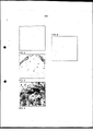
[0015] As figuras mostram: Figura 1 - dispositivo típico para remoção de camadas em processo eletrolítico de peças de trabalho. Figura 2 - superfície de uma peça de trabalho nova isto é ainda não revestida anteriormente. Figura 3 - superfície de uma peça de trabalho com camada removida com uma tensão constante de 8V Figura 4 - superfície de uma peça de taralho com camada removida com uma tensão constante de 16V. Figura 5 - sequenciamento da tensão de processo escalonado de acordo com a invenção. Figura 6 - apresenta superfície de uma peça de trabalho cuja remoção foi removida com a sequência do processo escalonado de acordo com a figura 5.[0015] The figures show: Figure 1 - typical device for removing layers in electrolytic process of work pieces. Figure 2 - surface of a new workpiece that is not previously coated. Figure 3 - Surface of a workpiece with layer removed with a constant voltage of 8V Figure 4 - Surface of a piece of workpiece with layer removed with a constant voltage of 16V. Figure 5 - stepping process voltage sequencing according to the invention. Figure 6 - shows the surface of a workpiece whose removal was removed with the sequence of the staggered process according to figure 5.
[0016] A invenção será agora descrita detalhadamente com relação as figuras e os exemplos[0016] The invention will now be described in detail with reference to the figures and examples
[0017] No exemplo devem ser liberados de camadas os chama dos tapetes de aço que estão revestidos com uma camada de CrN com espessura de 2 um e uma camada DLC com espessura de 2 um. Ou seja, trata-se no exemplo de um chamado sistema de duas camadas.[0017] In the example, the flame layers of the steel mats that are coated with a CrN layer with a thickness of 2 µm and a DLC layer with a thickness of 2 µm must be released from layers. That is, in the example, it is a so-called two-layer system.
[0018] A figura 1 apresenta uma instalação de remoção de camadas que contem um alojamento 1 em forma de paralelepípedo que contem um tanque 2 que consiste de material não condutor ou que no lado interno está revestido com um material não condutor de maneira que a parede interna não é condutora. Ela serve para receber um eletrólito. Além do tanque 1 está previsto uma saída de transbordamento 3 com uma peneira ou filtro.[0018] Figure 1 shows a layer removal installation that contains a
[0019] O eletrólito no exemplo é DECONEX HT1175 de cerca de 5% (% em vol.) em água de osmose.[0019] The electrolyte in the example is DECONEX HT1175 of about 5% (% by vol.) in osmosis water.
[0020] Em uma retenção 5, está acoplado um polo 72 de uma fonte de tensão 70 bipolar regulável. Na operação, a retenção 5 está ocupada com peças de trabalho 9 com camadas a serem removidas. Por motivo de melhor visibilidade a referencia mostra apenas três das peças trabalhadas. A fonte de tensão 70 é conformada como uma fonte de tensão regulável que permite uma regulagem contínua e/ou escalonado. Retenção 5 está de tal maneira unida com o alojamento 1 que pode ser removida sem grande esforço.[0020] In a
[0021] O outro polo da fonte de tensão 70 está unido com um contra eletrodo 12 conformado, por exemplo, como eletrodo de grade que está integrado no interior do tanque 2. O contra eletrodo 12 apresenta uma superfície voltada na direção do encaixe e que se estende essencialmente sobre toda a altura do tanque 2.[0021] The other pole of the
[0022] No tanque 2 estão dispostos além disso um dispositivo de aquecimento e de arrefecimento e um indicador de ultrassom bem como uma entrada para o eletrólito e conjuntos para a sua movimentação como bombas ou misturadores (todos não mostrados).[0022] In
[0023] Durante a operação o tanque 2 está cheio de um eletrólito liquido ate próxima da borda superior. A retenção 5 como também todos os demais componentes da instalação de remoção de camadas integrados no tanque 2 precisam consistir em um material que não seja atacado pelo eletrólito, geralmente de aço inoxidável ou, onde isto não for possível, como no caso de muitos materiais magnéticos, pode estar blindado em um laminado inoxidável.[0023] During operation,
[0024] A fonte de tensão 70 gera um diferencial de potencial entre a peça trabalhada e o contra eletrodo, cujo percurso corresponde aquele da figura 5.[0024] The
[0025] Para poder compreender a vantagem do presente pro- cesso será útil comparar a superfície de peças de trabalho com camadas removidas em um processo de remoção convencional e aquela de uma nova peça de trabalho não revestida com aquela superfície de uma peça de trabalho com a camada removida de acordo com a invenção.[0025] In order to understand the advantage of the present process it will be useful to compare the surface of workpieces with layers removed in a conventional removal process and that of a new uncoated workpiece with that surface of a workpiece with the layer removed according to the invention.
[0026] Neste sentido, a figura 2 apresenta uma nova peça de trabalho sem camadas. Apresenta apenas de forma muito reduzida e separada pequenos defeitos superficiais como, por exemplo, indicado com o número "1". Este defeito tem um diâmetro de apenas 3 um. Ao contrário a figura 3 apresenta superfície de uma peça de trabalho com camada removida com uma tensão constante de 8. Uma tensão desta intensidade resulta em um tempo de remoção de camada de cerca de duas horas. A peça de trabalho corresponde a peça de trabalho da figura 2. Podem se ver nitidamente defeitos na superfície. O número dos defeitos de superfície aumentou e também o seu diâmetro como mostra claramente a figura. Foram medidos três pontos de defeito "1, 2, 3" que produziram o diâmetro entre 13 μm e 18 μm. Também a figura 4 mostra uma peça de trabalho correspondente aquela da figura 1 cuja camada foi removida com tensão constante. A tensão aplicada durante a remoção da camada foi agora, todavia 16V. Desta maneira o tempo da remoção de camada pode ser reduzido a 10 min. Não obstante, comparado com a figura 3, verifica-se que o número dos defeitos e o seu tamanho novamente aumentou de forma dramática. Por exemplo, foram medidos três defeitos cujos diâmetros estavam situados entre 10 μm e 36 μm.[0026] In this sense, figure 2 presents a new workpiece without layers. It only presents very small and separate small surface defects as, for example, indicated with the number "1". This defect has a diameter of only 3 µm. In contrast, figure 3 shows the surface of a workpiece with a layer removed with a constant tension of 8. A tension of this intensity results in a layer removal time of about two hours. The workpiece corresponds to the workpiece in figure 2. Surface defects can be clearly seen. The number of surface defects has increased as well as their diameter as the figure clearly shows. Three defect points "1, 2, 3" were measured which produced the diameter between 13 μm and 18 μm. Also figure 4 shows a workpiece corresponding to that of figure 1 whose layer was removed with constant tension. The voltage applied during layer removal was now, however, 16V. In this way the layer removal time can be reduced to 10 min. Nevertheless, compared to Figure 3, it appears that the number of defects and their size again increased dramatically. For example, three defects were measured whose diameters were between 10 μm and 36 μm.
[0027] Contrário a este estado, a figura 6 mostra uma peça de trabalho com camada removida de acordo com o processo da invenção. A peça de trabalho correspondeu novamente àquela peça precedente. De modo correspondente a figura 5, durante os primeiros três minutos a tensão foi mantida em 3V. Este chamado estágio de segurança forma a primeira fase da remoção de camada. Neste supostamente será removido material de camada nos poros finos do substrato. Pelo fato de a tensão ser mantida reduzida, flui inicialmente, ao todo, corrente relativamente reduzido. A partir do terceiro minuto a tensão será ligeiramente aumentada para 3.5V. Já se formaram orifícios de camada na superfície do substrato cuja expansão aumenta continuamente. Supostamente o desbaste é feito princi-palmente na borda dos orifícios da camada. Com crescente expansão dos orifícios da camada também aumenta a borda ao todo existente de maneira que a quantidade global da corrente pode ser majorada sem danificar o substrato. Neste sentido, a partir do sexto minuto será feito um aumento para 4.5V. A partir do nono minuto será regulado uma tensão de 6V. A tensão será elevada a partir do décimo segundo minuto para 9V. A partir do décimo quinto minuto do processo a tensão será aumentada para 12V. Outro aumento da tensão agora para 16V será realizada a partir do décimo nono minuto. Se esta for a primeira remoção de camada após uma renovação do eletrólito, então a partir do vigésimo quarto minuto será regulada uma tensão de 17.5V. Ao todo, a remoção da camada durou, portanto apenas uma meia hora. Isto é nitidamente menos tempo do que em uma remoção de camada com o auxilio onde é necessário a tensão de 8V constante. Não obstante o menor tempo de remoção de camada, a superfície, como a figura 8 mostra nitidamente, será consideravelmente menos danificada do que no caso de aplicação de 8V constantes. Em comparação com a superfície de peça trabalhada não tratada de acordo com a figura 2, o número dos defeitos aumentou apenas de modo insignificante. O tamanho dos defeitos estava situado em 2 μm e 4 μm também na área da superfície não tradada. Desta maneira conseguiu-se, portanto que não obstante menor tempo de remoção de camadas é obtido uma superfície menos danifica- da.[0027] Contrary to this state, figure 6 shows a workpiece with layer removed according to the process of the invention. The workpiece matched that preceding piece again. Corresponding to figure 5, during the first three minutes the voltage was kept at 3V. This so-called security stage forms the first phase of layer removal. In this supposedly, layer material will be removed in the fine pores of the substrate. Because the voltage is kept low, relatively little current initially flows altogether. From the third minute the voltage will be slightly increased to 3.5V. Layer holes have already formed on the surface of the substrate whose expansion continuously increases. Supposedly, the thinning is done mainly on the edge of the holes in the layer. With increasing expansion of the holes in the layer, the overall existing edge also increases so that the overall amount of current can be increased without damaging the substrate. In this sense, from the sixth minute onwards, an increase will be made to 4.5V. From the ninth minute, a voltage of 6V will be regulated. The voltage will be raised from the twelfth minute to 9V. From the fifteenth minute of the process, the voltage will be increased to 12V. Another voltage increase now to 16V will be carried out from the nineteenth minute. If this is the first layer removal after an electrolyte renewal, then from the twenty-fourth minute a voltage of 17.5V will be regulated. All in all, the layer removal took, therefore, only half an hour. This is markedly less time than in an assisted layer removal where a constant 8V voltage is required. Despite the shorter layer removal time, the surface, as Figure 8 clearly shows, will be considerably less damaged than in the case of constant 8V application. Compared to the untreated workpiece surface according to figure 2, the number of defects has increased only insignificantly. The size of the defects was situated at 2 μm and 4 μm also in the untreated surface area. In this way, it was therefore achieved that despite a shorter layer removal time, a less damaged surface is obtained.
[0028] A sequência da tensão a ser selecionada será preferencialmente adequada a diferentes tipos de peças de trabalho e a diferentes tipos de camada a fim de aperfeiçoar o processo. É, todavia, importante que se inicie com uma tensão reduzida e visando evitar defeitos. De acordo com a invenção está tensão será depois aumentada para minimizar o tempo de remoção de camada necessário.[0028] The voltage sequence to be selected will preferably be suitable for different types of workpieces and different types of layer in order to optimize the process. It is, however, important to start with a low voltage and to avoid defects. In accordance with the invention this voltage will then be increased to minimize the required layer removal time.
[0029] Existem diferentes possibilidade como o especialista po de alcançar um sequenciamento de tensão otimizado, por exemplo, em uma primeira série de testes poderá realizar processos sequenciais de remoção de camadas com uma tensão constante porem variável e intensa, examinado desta maneira até qual tensão permanece intacta uma superfície ainda aceitável, isto é suficientemente intacta. Esta tensão será depois determinada como tensão de partida V1[0029] There are different possibilities how the specialist can achieve an optimized voltage sequencing, for example, in a first series of tests, he will be able to carry out sequential processes of layer removal with a constant but variable and intense voltage, examined in this way until which voltage a still acceptable surface remains intact, that is, sufficiently intact. This voltage will then be determined as the starting voltage V1
[0030] Em uma segunda série de testes, o especialista fará en tão através de um intervalo de partida de remoção de camada El1 a regulagem desta tensão de partida determinada V1, e após este intervalo do tempo de remoção de camadas El1 aumentará a tensão e a partir dali novamente com tensão agora constante mais diferenciado por cada teste continuará a remoção de camada. Desta maneira poderá testar em que intensidade ele poderá selecionar a tensão após o intervalo da partida sem danificar a superfície adicionalmente. A tensão V2 assim determinada e que na sua extensão é maior do que V1 será novamente em nível constante durante o segundo intervalo de remoção de camada El2.[0030] In a second series of tests, the specialist will then, through a starting interval of layer removal El1, the adjustment of this determined starting voltage V1, and after this interval the layer removal time El1 will increase the voltage and from there again with voltage now constant more differentiated by each test layer removal will continue. This way you can test at what intensity it can select the voltage after the start interval without further damaging the surface. The voltage V2 thus determined and which in its extent is greater than V1 will again be at constant level during the second layer removal interval E12.
[0031] Segue-se uma série de testes até o terceiro intervalo de remoção de camada El3 sendo inicialmente através de El1 com V1 e depois através de El2 é feita a remoção de camadas com V2 e depois com uma tensão variada porém constante será feita a remoção completa de camadas. Desta maneira alcança-se uma tensão V3 máxima na qual a superfície essencialmente não é atacada adicionalmente.[0031] A series of tests follows until the third layer removal interval El3 being initially through El1 with V1 and then through El2 the removal of layers with V2 is done and then with a varied but constant voltage the complete layer removal. In this way a maximum voltage V3 is reached at which the surface is essentially not attacked further.
[0032] Fica a cargo do especialista a escolha dos intervalos. Es tes podem ser todos de duração igual ou também podem ser selecionados de duração variada. Quanto menores forem os diferentes intervalos de remoção de camada tanto mais complexa será a realização das séries de testes e tanto melhor poderá ser feita, todavia uma próxima ao processo escalonado ótimo. Em caso extremo pode até mesmo ser logrado um percurso de tensão de aumento contínuo. A partir de um determinado período curto de intervalo este poderá também ser interpolado sem outras séries de testes.[0032] It is up to the specialist to choose the intervals. These can all be of equal duration or can also be selected of varying duration. The smaller the different layer removal intervals, the more complex the test series will be and the better it can be done, however close to the optimal staggered process. In extreme cases, a continuously increasing voltage path can even be achieved. After a short period of time, this can also be interpolated without further test series.
[0033] Preferencialmente, o sequenciamento da tensão aplicado de acordo com a invenção ficara monótono, e preferencialmente até mesmo aumentará de forma intensamente monótona. Não obstante a partir do acima exposto deve ficar claro que uma redução por curto espaço de tempo da tensão não danificará a superfície do substrato de maneira que também percursos de tensão devem ser considerados como inventivos que não aumentam de forma monótona, porém permitem uma tensão menor por uma determinada faixa. Isto vale especialmente também para tensões alternadas aplicadas que, por exemplo, na fase de partida são limitadas a amplitudes pequenas e durante o processo da remoção de camadas aumentam ate amplitude mais elevadas. Séries de testes análogos as acima descritas permitem ao especialista novamente aproximar-se do percurso de tensão ótimo.[0033] Preferably, the voltage sequencing applied in accordance with the invention will become monotonous, and preferably even increase in an intensely monotonous manner. Notwithstanding the foregoing, it should be clear that a short-term reduction of the tension will not damage the surface of the substrate, so that tension paths must also be considered as inventive paths that do not increase monotonously, but allow for a lower tension. by a certain range. This is especially true also for applied alternating voltages which, for example, in the starting phase are limited to small amplitudes and during the layering process increase to higher amplitudes. Analogous test series to those described above allow the specialist to again approach the optimal stress path.
[0034] De preferência, naquelas camadas que devem ser remo vidas de peças de trabalho trata-se de camadas porosas. Desta maneira é assegurado que na aplicação de uma tensão fraca já se verifica um fluxo de corrente e, portanto, uma reação eletrolítica.[0034] Preferably, those layers that are to be removed from workpieces are porous layers. In this way it is ensured that in the application of a weak voltage there is already a flow of current and, therefore, an electrolytic reaction.
[0035] Uma característica do processo discutido é que no caso de uma peça totalmente livre de camada e com a tensão elevada continuando aplicada (por exemplo, 16V) não se apresentou dano no substrato. Desta maneira um critério de desligamento para o processo de remoção de camadas não é crítico[0035] A characteristic of the process discussed is that in the case of a piece totally free of layer and with the high voltage still applied (for example, 16V) there was no damage to the substrate. In this way, a shutdown criterion for the layer removal process is not critical.
[0036] Nos exemplos seguintes o processo foi testado com base de camadas substratos e eletrólitos diferenciados e não metálicos e comparados com o processo de tensão constante de acordo com o estado da técnica:[0036] In the following examples the process was tested based on layers of differentiated and non-metallic substrates and electrolytes and compared with the constant voltage process according to the state of the art:
[0037] Substrato TIAL liga como, por exemplo, é emprego no es porte de corridas para componentes. Camada igual CRC entre 3 - 5um[0037] Substrate TIAL alloy as, for example, is used in racing sport for components. Equal layer CRC between 3 - 5um
[0038] Eletrólito: 5% Deconex HT1175[0038] Electrolyte: 5% Deconex HT1175
[0039] Percursos de tensão: a) Constante 10V durante 7 - 10 min b) Constante 8V durante 10 a 15 min c) 3V 3m, 5V 5 min, 6V 5 min[0039] Voltage paths: a) Constant 10V for 7 - 10 min b) Constant 8V for 10 to 15 min c) 3V 3m,
[0040] As peças tiveram as camadas removidas com o processo a) - c) a qualidade da remoção da camada de a) - c) foi realizada o que é mostrado em uma diminuição da coloração do substrato sem camadas de a) até c), de modo correspondente, o substrato com camada removida de acordo com a) apresenta um tingimento muito forte, o substrato com a camada removida de acordo com b) apresenta um tingimento parcial e o substrato com camada removida de acordo com a invenção c) não apresenta tingimento.[0040] The pieces had the layers removed with the process a) - c) the quality of the layer removal from a) - c) was performed which is shown in a decrease in the color of the substrate without layers from a) to c) , correspondingly, the peel-off substrate according to a) is very strongly dyed, the peel-off substrate according to b) is partially dyed, and the peel-off substrate according to the invention c) is not presents dyeing.
[0041] Substrato: aço 1.2379 como, por exemplo, empregado pa ra construção de formas.[0041] Substrate: 1.2379 steel as, for example, used for the construction of forms.
[0042] Camada: CrN entre 3 - 5 um[0042] Layer: CrN between 3 - 5 um
[0043] Eletrólito: 2% Na0H[0043] Electrolyte: 2% Na0H
[0044] Percursos de tensão a) Constante 12V durante 10 a 15 min. b) Constante 7,5v durante 10 a 25 min. c) 2.5V 3 min, 5V 5min, 8V 7min, 10V 7min.[0044] Voltage paths a) Constant 12V for 10 to 15 min. b) Constant 7.5v for 10 to 25 min. c) 2.5V 3min, 5V 5min, 8V 7min, 10V 7min.
[0045] As peças tiveram as camadas removidas como processo a) - c) e a qualidade da remoção de camada aumenta de a) - ate c)[0045] The parts had the layers removed as process a) - c) and the quality of the layer removal increases from a) - to c)
[0046] Substrato: aço HSS (fresa de cilindro) como, por exemplo, usado para ferramentas.[0046] Substrate: HSS steel (cylinder milling cutter) such as used for tools.
[0047] Camada: AlCrN entre 3 - 5um[0047] Layer: AlCrN between 3 - 5um
[0048] Eletrólito: 5% Deconex HT1175[0048] Electrolyte: 5% Deconex HT1175
[0049] Substrato: metal duro K - tipo (perfuratriz) como, por exemplo usado para ferramentas.[0049] Substrate: K-type carbide (drill) as eg used for tools.
[0050] Camada: AlCrN entre 3 - 5um[0050] Layer: AlCrN between 3 - 5um
[0051] Eletrólito: NH4/NO3/CH3COOH (ver EP 1080254)[0051] Electrolyte: NH4/NO3/CH3COOH (see EP 1080254)
[0052] Percursos de tensão: a) Constante 15V durante 3 - 60s b) 2.8V 10 s, 5V 10s, 8V 10s, 10V 10s,[0052] Voltage paths: a) Constant 15V for 3 - 60s b) 2.8V 10s, 5V 10s, 8V 10s, 10V 10s,
[0053] As peças tiveram a camada removida uma vez com o pro cesso a) e uma vez com o processo b), a qualidade da remoção de camadas em b) é melhor do que em a), para remoção das camadas foi usado um catodo cilíndrico.[0053] The pieces had the layer removed once with process a) and once with process b), the quality of layer removal in b) is better than in a), to remove the layers a cylindrical cathode.
[0054] Foi realizado um processo para remoção de camadas em peças de trabalho com revestimento de superfícies não condutoras elétricas, sendo que o processo foi realizado com eletrólito e abrange os seguintes passos: - preparação de um tanque sendo que no interior do tanque está previsto um eletrodo que pode ser acoplado em um conjunto de abastecimento de corrente, - enchimento de um eletrólito no tanque de maneira que o eletrodo entra em contado com o eletrólito, - submersão de uma ou varias peças trabalhadas no eletró- lito, - aplicação de uma tensão entre a peça de trabalho e o eletrodo para a remoção de camadas ao menos parcial na peça de trabalho, sendo que durante a remoção de camadas ao menos parcial a tensão será regulado de tal maneira que em um primeiro momento é aplicado uma primeira tensão e um momento posterior é aplicado uma segunda tensão mais elevada em comparação com a primeira tensão, a qual não conduz na formação de orifícios, sendo que a aplicação da segunda tensão mais elevada no primeiro momento teria resultado na formação de orifícios.[0054] A process was carried out to remove layers in workpieces with coating of electrically non-conductive surfaces, and the process was carried out with electrolyte and covers the following steps: - preparation of a tank, in which the interior of the tank is provided for an electrode which can be coupled to a current supply set, - filling an electrolyte into the tank so that the electrode comes into contact with the electrolyte, - submerging one or more workpieces in the electrolyte, - applying a voltage between the workpiece and the electrode for the removal of at least partial layers on the workpiece, whereby during the removal of at least partial layers the voltage will be regulated in such a way that at first a first voltage is applied and at a later moment a higher second stress is applied compared to the first stress, which does not lead to the formation of holes, whereby the application of the second stress higher at the first moment would have resulted in the formation of holes.
[0055] De preferência, durante ao menos a remoção de camada parcial a tensão será regulada de tal maneira que a extensão da diferença potencial entre o eletrodo e a peça de trabalho aumenta de forma contínua e/ou gradual.[0055] Preferably, during at least partial layer removal the voltage will be regulated in such a way that the extent of the potential difference between the electrode and the workpiece increases continuously and/or gradually.
[0056] Preferencialmente a tensão será especialmente regulada de tal maneira que a diferença potencial durante a remoção de camadas parcial aumenta de forma monótona, preferencialmente intensamente monótona.[0056] Preferably the voltage will be specially regulated in such a way that the potential difference during partial layer removal increases monotonously, preferably intensely monotonously.
[0057] A tensão também poderá ser regulada de tal maneira que no início da remoção de camadas, através de um primeiro intervalo de tempo El1 a diferença de potencial é essencialmente mantida constante em um primeiro valor U1 e a diferença potencial em um intervalo de tempo El2, sequencial ao primeiro intervalo de tempo, é mantida em nível constante em um segundo valor U2 sendo que é válido U1 < U2[0057] The voltage may also be regulated in such a way that at the beginning of layer removal, through a first time interval El1 the potential difference is essentially kept constant at a first value U1 and the potential difference at a time interval El2, sequential to the first time interval, is kept at a constant level in a second value U2, where U1 < U2 is valid
Claims (4)
Applications Claiming Priority (3)
| Application Number | Priority Date | Filing Date | Title |
|---|---|---|---|
| DE102010046372A DE102010046372A1 (en) | 2010-09-24 | 2010-09-24 | Method for stripping workpieces |
| DE102010046372.8 | 2010-09-24 | ||
| PCT/EP2011/004739 WO2012038083A1 (en) | 2010-09-24 | 2011-09-22 | Process for removing a coating from workpieces |
Publications (2)
| Publication Number | Publication Date |
|---|---|
| BR112013008665A2 BR112013008665A2 (en) | 2016-06-21 |
| BR112013008665B1 true BR112013008665B1 (en) | 2022-04-05 |
Family
ID=44735874
Family Applications (1)
| Application Number | Title | Priority Date | Filing Date |
|---|---|---|---|
| BR112013008665-3A BR112013008665B1 (en) | 2010-09-24 | 2011-09-22 | Process for removing layers of workpieces |
Country Status (13)
| Country | Link |
|---|---|
| US (1) | US9512539B2 (en) |
| EP (1) | EP2619354B1 (en) |
| JP (1) | JP6086866B2 (en) |
| KR (1) | KR101781244B1 (en) |
| CN (1) | CN103109000B (en) |
| BR (1) | BR112013008665B1 (en) |
| CA (1) | CA2811530C (en) |
| DE (1) | DE102010046372A1 (en) |
| MX (1) | MX336499B (en) |
| MY (1) | MY162839A (en) |
| RU (1) | RU2579717C2 (en) |
| SG (1) | SG189041A1 (en) |
| WO (1) | WO2012038083A1 (en) |
Families Citing this family (2)
| Publication number | Priority date | Publication date | Assignee | Title |
|---|---|---|---|---|
| KR20170004970A (en) * | 2014-03-18 | 2017-01-11 | 플라티트 아게 | Method for delamination of ceramic hard material layers from steel and cemented carbide substrates |
| WO2023217411A2 (en) | 2022-05-09 | 2023-11-16 | Oerlikon Surface Solutions Ag, Pfäffikon | Use of sulfonic acids in dry electrolytes to remove vapor deposited and/or thermally sprayed coatings on metal surfaces |
Family Cites Families (15)
| Publication number | Priority date | Publication date | Assignee | Title |
|---|---|---|---|---|
| GB1399710A (en) | 1972-11-08 | 1975-07-02 | Electricity Council | Electrolytic cleaning of metal surfaces |
| RU2034937C1 (en) * | 1991-05-22 | 1995-05-10 | Кабардино-Балкарский государственный университет | Method for electrochemical treatment of products |
| EP1080254B1 (en) | 1998-04-21 | 2003-07-02 | Unaxis Balzers Aktiengesellschaft | Method for removing a hard material layer deposited on a hard metal work piece |
| EP1362934B1 (en) * | 1998-04-21 | 2011-07-20 | Oerlikon Trading AG, Trübbach | Fixing device for at least one workpiece |
| WO1999064646A1 (en) * | 1998-06-11 | 1999-12-16 | Unaxis Trading Ag | Method for removing layers of hard material |
| DE19840471A1 (en) * | 1998-09-04 | 2000-03-09 | Schmid Gmbh & Co Geb | Apparatus for removal of coating from an article comprises devices which monitor voltage and/or current or potential variation, and are electrically connected to the control system of the apparatus |
| US6627064B1 (en) * | 2000-10-23 | 2003-09-30 | Unaxis Balzers Aktiengesellschaft | Method for removing the hard material coating applied on a hard metal workpiece and a holding device for at least one workpiece |
| US6969457B2 (en) * | 2002-10-21 | 2005-11-29 | General Electric Company | Method for partially stripping a coating from the surface of a substrate, and related articles and compositions |
| DE102004002763A1 (en) * | 2004-01-20 | 2005-08-04 | Mtu Aero Engines Gmbh | Method for electrochemical removal of layers from components with prior determination of a working point for their removal useful for stripping coated gas turbine blades |
| ATE389739T1 (en) * | 2004-06-30 | 2008-04-15 | Siemens Ag | METHOD AND DEVICE FOR SURFACE TREATMENT OF A COMPONENT |
| WO2007015454A1 (en) * | 2005-08-01 | 2007-02-08 | Hitachi Zosen Corporation | Method and device for removing conductive metal oxide thin film |
| US20070187258A1 (en) * | 2006-02-15 | 2007-08-16 | Tianbao Du | Method for electrochemically polishing a conductive material on a substrate |
| CN101058894B (en) * | 2006-04-19 | 2010-08-25 | 鸿富锦精密工业(深圳)有限公司 | Method of removing diamond-like carbon film |
| US8361290B2 (en) * | 2006-09-05 | 2013-01-29 | Oerlikon Trading, Ag, Trubbach | Coating removal installation and method of operating it |
| JP4435250B2 (en) * | 2008-08-12 | 2010-03-17 | エリコン・トレーディング・アクチェンゲゼルシャフト,トリュープバッハ | Fixing device for at least one workpiece |
-
2010
- 2010-09-24 DE DE102010046372A patent/DE102010046372A1/en not_active Withdrawn
-
2011
- 2011-09-22 EP EP11764105.0A patent/EP2619354B1/en not_active Not-in-force
- 2011-09-22 MX MX2013003347A patent/MX336499B/en unknown
- 2011-09-22 RU RU2013118686/02A patent/RU2579717C2/en active
- 2011-09-22 BR BR112013008665-3A patent/BR112013008665B1/en not_active IP Right Cessation
- 2011-09-22 WO PCT/EP2011/004739 patent/WO2012038083A1/en active Application Filing
- 2011-09-22 MY MYPI2013000989A patent/MY162839A/en unknown
- 2011-09-22 CN CN201180045840.4A patent/CN103109000B/en not_active Expired - Fee Related
- 2011-09-22 CA CA2811530A patent/CA2811530C/en not_active Expired - Fee Related
- 2011-09-22 KR KR1020137007490A patent/KR101781244B1/en active IP Right Grant
- 2011-09-22 JP JP2013529578A patent/JP6086866B2/en not_active Expired - Fee Related
- 2011-09-22 US US13/823,767 patent/US9512539B2/en active Active
- 2011-09-22 SG SG2013021019A patent/SG189041A1/en unknown
Also Published As
| Publication number | Publication date |
|---|---|
| WO2012038083A1 (en) | 2012-03-29 |
| MY162839A (en) | 2017-07-31 |
| MX336499B (en) | 2016-01-20 |
| CA2811530C (en) | 2018-07-03 |
| DE102010046372A1 (en) | 2012-03-29 |
| CN103109000A (en) | 2013-05-15 |
| JP2013544955A (en) | 2013-12-19 |
| SG189041A1 (en) | 2013-05-31 |
| EP2619354B1 (en) | 2019-01-09 |
| KR20130108313A (en) | 2013-10-02 |
| CA2811530A1 (en) | 2012-03-29 |
| CN103109000B (en) | 2018-06-26 |
| JP6086866B2 (en) | 2017-03-01 |
| RU2013118686A (en) | 2014-10-27 |
| BR112013008665A2 (en) | 2016-06-21 |
| EP2619354A1 (en) | 2013-07-31 |
| RU2579717C2 (en) | 2016-04-10 |
| KR101781244B1 (en) | 2017-09-26 |
| MX2013003347A (en) | 2013-06-24 |
| US9512539B2 (en) | 2016-12-06 |
| US20130240373A1 (en) | 2013-09-19 |
Similar Documents
| Publication | Publication Date | Title |
|---|---|---|
| Russell et al. | Anodic Dissolution of Iron in Acidic Sulfate Electrolytes: II. Mathematical Model of Current Oscillations Observed under Potentiostatic Conditions | |
| Datta et al. | On the role of mass transport in high rate dissolution of iron and nickel in ECM electrolytes—I. Chloride solutions | |
| Landolt | Fundamental aspects of electropolishing | |
| Rosenkranz et al. | The surface structure during pulsed ECM of iron in NaNO3 | |
| BRPI1010877B1 (en) | CORROSION RESISTANT MULTILAYER COATING AND ELECTRODEPOSITION METHOD | |
| US20160053398A1 (en) | Graphene Anti-Corrosion Coating and Method of Application Thereof | |
| US20120000784A1 (en) | Power supply for anodizing, anodizing method, and anodized film | |
| Naderi et al. | Effect of zinc-free phosphate-based anticorrosion pigment on the cathodic disbondment of epoxy-polyamide coating | |
| CN111593384A (en) | Helicopter main hub plating damage repairing method and device | |
| BR112013008665B1 (en) | Process for removing layers of workpieces | |
| Corcoran et al. | Chaos during the growth of an artificial pit | |
| Li et al. | Effects of polyvinylidene fluoride sealing on micro-arc oxidation coating of 7075 aluminum alloy | |
| US8425751B1 (en) | Systems and methods for the electrodeposition of a nickel-cobalt alloy | |
| Taylor et al. | A pulse/pulse reverse electrolytic approach to electropolishing and through-mask electroetching | |
| Hu et al. | Kinetics analysis of Ni-TiO 2 composite system during initial stages of electro-crystallization | |
| CN105780085B (en) | A kind of method of uranium surface differential arc oxidation | |
| Ghanbari et al. | Corrosion behavior of zirconium treated mild steel with and without organic coating: a comparative study | |
| Bhatnagar et al. | Selective electrodeposition of zinc–nickel alloy through porous medium | |
| JP6011559B2 (en) | Metal film deposition method | |
| EP3461933A1 (en) | Method for electrolytically depositing a zinc-nickel alloy layer on at least a substrate to be treated | |
| Domanski | The electrodeposition of metallic molybdenum thin-film coatings, from aqueous electrolytes containing molybdate ions | |
| Li et al. | Influence of fluoride and chromium (VI) ions on corrosion mechanisms of Pb-3wt% sn-0.5 wt% Ag anode | |
| JPH06100570B2 (en) | Life prediction method for coated metal | |
| RU2078856C1 (en) | Process of deposition of coat | |
| Ziomek-Moroz | Electropolishing |
Legal Events
| Date | Code | Title | Description |
|---|---|---|---|
| B06F | Objections, documents and/or translations needed after an examination request according [chapter 6.6 patent gazette] | ||
| B06T | Formal requirements before examination [chapter 6.20 patent gazette] | ||
| B09A | Decision: intention to grant [chapter 9.1 patent gazette] | ||
| B25D | Requested change of name of applicant approved |
Owner name: OERLIKON SURFACE SOLUTIONS AG, TRUEBBACH (CH) |
|
| B25D | Requested change of name of applicant approved |
Owner name: OERLIKON SURFACE SOLUTIONS AG, PFAEFFIKON (CH) |
|
| B25G | Requested change of headquarter approved |
Owner name: OERLIKON SURFACE SOLUTIONS AG, PFAEFFIKON (CH) |
|
| B16A | Patent or certificate of addition of invention granted [chapter 16.1 patent gazette] |
Free format text: PRAZO DE VALIDADE: 20 (VINTE) ANOS CONTADOS A PARTIR DE 22/09/2011, OBSERVADAS AS CONDICOES LEGAIS. PATENTE CONCEDIDA CONFORME ADI 5.529/DF, QUE DETERMINA A ALTERACAO DO PRAZO DE CONCESSAO. |
|
| B21F | Lapse acc. art. 78, item iv - on non-payment of the annual fees in time |
Free format text: REFERENTE A 12A ANUIDADE. |
|
| B24J | Lapse because of non-payment of annual fees (definitively: art 78 iv lpi, resolution 113/2013 art. 12) |
Free format text: EM VIRTUDE DA EXTINCAO PUBLICADA NA RPI 2741 DE 18-07-2023 E CONSIDERANDO AUSENCIA DE MANIFESTACAO DENTRO DOS PRAZOS LEGAIS, INFORMO QUE CABE SER MANTIDA A EXTINCAO DA PATENTE E SEUS CERTIFICADOS, CONFORME O DISPOSTO NO ARTIGO 12, DA RESOLUCAO 113/2013. |