BR112012017231B1 - VEHICLE RETENTION BED - Google Patents
VEHICLE RETENTION BED Download PDFInfo
- Publication number
- BR112012017231B1 BR112012017231B1 BR112012017231-0A BR112012017231A BR112012017231B1 BR 112012017231 B1 BR112012017231 B1 BR 112012017231B1 BR 112012017231 A BR112012017231 A BR 112012017231A BR 112012017231 B1 BR112012017231 B1 BR 112012017231B1
- Authority
- BR
- Brazil
- Prior art keywords
- bed
- aggregate
- size
- spongy
- weight
- Prior art date
Links
Images


Classifications
-
- E—FIXED CONSTRUCTIONS
- E01—CONSTRUCTION OF ROADS, RAILWAYS, OR BRIDGES
- E01C—CONSTRUCTION OF, OR SURFACES FOR, ROADS, SPORTS GROUNDS, OR THE LIKE; MACHINES OR AUXILIARY TOOLS FOR CONSTRUCTION OR REPAIR
- E01C9/00—Special pavings; Pavings for special parts of roads or airfields
- E01C9/007—Vehicle decelerating or arresting surfacings or surface arrangements, e.g. arrester beds ; Escape roads, e.g. for steep descents, for sharp bends
-
- B—PERFORMING OPERATIONS; TRANSPORTING
- B64—AIRCRAFT; AVIATION; COSMONAUTICS
- B64F—GROUND OR AIRCRAFT-CARRIER-DECK INSTALLATIONS SPECIALLY ADAPTED FOR USE IN CONNECTION WITH AIRCRAFT; DESIGNING, MANUFACTURING, ASSEMBLING, CLEANING, MAINTAINING OR REPAIRING AIRCRAFT, NOT OTHERWISE PROVIDED FOR; HANDLING, TRANSPORTING, TESTING OR INSPECTING AIRCRAFT COMPONENTS, NOT OTHERWISE PROVIDED FOR
- B64F1/00—Ground or aircraft-carrier-deck installations
- B64F1/02—Arresting gear; Liquid barriers
- B64F1/025—Arresting gear; Liquid barriers using decelerating or arresting beds
-
- B—PERFORMING OPERATIONS; TRANSPORTING
- B64—AIRCRAFT; AVIATION; COSMONAUTICS
- B64F—GROUND OR AIRCRAFT-CARRIER-DECK INSTALLATIONS SPECIALLY ADAPTED FOR USE IN CONNECTION WITH AIRCRAFT; DESIGNING, MANUFACTURING, ASSEMBLING, CLEANING, MAINTAINING OR REPAIRING AIRCRAFT, NOT OTHERWISE PROVIDED FOR; HANDLING, TRANSPORTING, TESTING OR INSPECTING AIRCRAFT COMPONENTS, NOT OTHERWISE PROVIDED FOR
- B64F1/00—Ground or aircraft-carrier-deck installations
- B64F1/02—Arresting gear; Liquid barriers
-
- C—CHEMISTRY; METALLURGY
- C04—CEMENTS; CONCRETE; ARTIFICIAL STONE; CERAMICS; REFRACTORIES
- C04B—LIME, MAGNESIA; SLAG; CEMENTS; COMPOSITIONS THEREOF, e.g. MORTARS, CONCRETE OR LIKE BUILDING MATERIALS; ARTIFICIAL STONE; CERAMICS; REFRACTORIES; TREATMENT OF NATURAL STONE
- C04B14/00—Use of inorganic materials as fillers, e.g. pigments, for mortars, concrete or artificial stone; Treatment of inorganic materials specially adapted to enhance their filling properties in mortars, concrete or artificial stone
- C04B14/02—Granular materials, e.g. microballoons
- C04B14/04—Silica-rich materials; Silicates
- C04B14/22—Glass ; Devitrified glass
- C04B14/24—Glass ; Devitrified glass porous, e.g. foamed glass
-
- C—CHEMISTRY; METALLURGY
- C04—CEMENTS; CONCRETE; ARTIFICIAL STONE; CERAMICS; REFRACTORIES
- C04B—LIME, MAGNESIA; SLAG; CEMENTS; COMPOSITIONS THEREOF, e.g. MORTARS, CONCRETE OR LIKE BUILDING MATERIALS; ARTIFICIAL STONE; CERAMICS; REFRACTORIES; TREATMENT OF NATURAL STONE
- C04B2111/00—Mortars, concrete or artificial stone or mixtures to prepare them, characterised by specific function, property or use
- C04B2111/00474—Uses not provided for elsewhere in C04B2111/00
- C04B2111/0075—Uses not provided for elsewhere in C04B2111/00 for road construction
Landscapes
- Engineering & Computer Science (AREA)
- Chemical & Material Sciences (AREA)
- Ceramic Engineering (AREA)
- Mechanical Engineering (AREA)
- Aviation & Aerospace Engineering (AREA)
- Structural Engineering (AREA)
- Civil Engineering (AREA)
- Organic Chemistry (AREA)
- Materials Engineering (AREA)
- Architecture (AREA)
- Road Paving Structures (AREA)
- Seats For Vehicles (AREA)
- Paints Or Removers (AREA)
- Refuge Islands, Traffic Blockers, Or Guard Fence (AREA)
- Porous Artificial Stone Or Porous Ceramic Products (AREA)
- Emergency Lowering Means (AREA)
Abstract
leito de retenção de veículos a presente invenção está correlacionada a leitos de retenção para desaceleração de veículos, especialmente de aeronave de passageiros incapazes de parar em pistas de pouso disponíveis, em que o sistema compreende uma área de retenção de veículo (a), compreendendo um leito cheio de agregado de vidro esponjoso (1), com tamanhos de partículas variando de 0,25 cm a 15 cm, e frações de vazios nominais de cerca de 70 a 98%, e uma cobertura de topo (4) cobrindo a superfície superior do leito de agregado de vidro esponjoso.vehicle restraint bed the present invention is related to vehicle restraint beds, especially of passenger aircraft unable to stop on available airstrips, in which the system comprises a vehicle restraint area (a), comprising a bed filled with spongy glass aggregate (1), with particle sizes ranging from 0.25 cm to 15 cm, and nominal void fractions of about 70 to 98%, and a top cover (4) covering the upper surface the bed of spongy glass aggregate.
Description
A presente invenção está correlacionada a leitos de retenção para desacelerar veículos, tais como, aeronaves, incapazes de parar em pistas de pouso disponíveis.The present invention is related to detention beds to slow vehicles, such as aircraft, unable to stop on available airstrips.
Um dos problemas de segurança na aviação é o das aeronaves durante a decolagem ou aterrissagem, ocasionalmente com invasões das pistas de pouso disponíveis e que terminam em terrenos atrás da pista de pouso. Existem diversos exemplos de tais acidentes com resultados catastróficos, tanto em termos de danos materiais, como em perdas de vida ou graves danos à saúde de pessoas envolvidas. Isso é identificado em uma faixa de possíveis causas desses tipos de acidentes, tais como, descoberta nos últimos instantes de falhas mecânicas da aeronave que tornam necessário abortar a decolagem, falhas de frenagem da aeronave, inesperados incidentes de condições do tempo, Eros do piloto, etc. A grande variedade de causas que provocam essas invasões torna improvável a possibilidade de introduzir medidas para totalmente evitar essas situações na aviação.One of the safety problems in aviation is that of aircraft during takeoff or landing, occasionally with invasions of available airstrips that end up on terrain behind the airstrip. There are several examples of such accidents with catastrophic results, both in terms of material damage, loss of life or serious damage to the health of the people involved. This is identified in a range of possible causes of these types of accidents, such as, discovered in the last moments of mechanical failures of the aircraft that make it necessary to abort the takeoff, aircraft braking failures, unexpected incidents of weather conditions, Eros of the pilot, etc. The wide variety of causes that cause these invasions makes it unlikely that measures will be introduced to totally prevent these situations in aviation.
Assim, para aliviar e evitar as graves consequências de situações de invasão é necessário a provisão de pistas de pouso com meios de captura e/ou retardamento de aeronaves que invadem a pista de pouso, de uma maneira segura. Para aeródromos com amplo espaço disponível por trás da pista de pouso, uma solução óbvia seria simplesmente prolongar a pista de pouso para permitir às aeronaves um amplo espaço para parar, através do uso de freios ou da força de reversão do motor.Thus, in order to alleviate and avoid the serious consequences of invasion situations, it is necessary to provide airstrips with means of capturing and / or delaying aircraft that invade the airstrip in a safe manner. For airfields with ample space available behind the airstrip, an obvious solution would be to simply extend the airstrip to allow aircraft ample space to stop, either by using brakes or by reversing the engine.
Entretanto, diversos aeródromos não possuem espaço disponível para prover um suficiente prolongamento da pista de pouso e também existem incidentes onde uma invasão é causada por mau funcionamento dos sistemas de freios das aeronaves. Portanto, é vantajosa a provisão de aeródromos com um ou mais dispositivos para exercer uma força de desaceleração externa nas aeronaves que invadem a extremidade da pista de pouso e que são capazes de forçar a aeronave a parar em uma velocidade de desaceleração que é tolerável para a construção mecânica da aeronave, especialmente, do trem de pouso, e das pessoas a bordo da aeronave.However, several aerodromes do not have space available to provide sufficient length of the airstrip and there are also incidents where an invasion is caused by malfunction of the aircraft's brake systems. Therefore, it is advantageous to provide aerodromes with one or more devices to exert an external deceleration force on aircraft that invade the end of the landing strip and which are able to force the aircraft to stop at a deceleration speed that is tolerable for the mechanical construction of the aircraft, especially the landing gear, and the people on board the aircraft.
Uma solução conhecida para fazer parar aeronaves (ou outros veículos de rodas) é proporcionar uma zona retentora. Uma zona retentora é uma zona feita de um leito raso de um material relativamente maleável por cima de um material duro, capaz de suportar as rodas do veículo. Quando um veículo entra na zona retentora, suas rodas irão afundar um pouco dentro do material macio e, desse modo, obter um significativo aumento de arraste da carga. A massa maleável da zona retentora, desse modo, absorve a energia cinética do veículo e proporciona ao mesmo uma parada segura. As zonas retentoras são vantajosas para uso em aeródromos pelo fato de serem de natureza passiva e não possuírem partes móveis, de modo que estão sempre prontas para uso.A known solution for stopping aircraft (or other wheeled vehicles) is to provide a restraint zone. A retaining zone is a zone made up of a shallow bed of relatively malleable material on top of a hard material, capable of supporting the vehicle's wheels. When a vehicle enters the retaining zone, its wheels will sink a little into the soft material and thus obtain a significant increase in the drag of the load. The malleable mass of the retaining zone thus absorbs the vehicle's kinetic energy and provides it with a safe stop. The retaining zones are advantageous for use at aerodromes because they are passive in nature and have no moving parts, so they are always ready for use.
Um exemplo de zonas retentoras é divulgado na Patente U.S. No. 3.066.896, onde a zona retentora consiste de uma disposição de bacia rasa cheia de líquido, de extensão de cerca de 300 m, colocada na extremidade da pista de pouso, e que é coberta com uma forte, mas, flexível, cobertura de topo. A bacia cheia de líquido com a cobertura de topo irá formar uma zona maleável na extremidade da pista de pouso, que será rebaixada pelas rodas de uma aeronave que circula na cobertura de topo.Devido à necessidade de impulsionar para fora o líquido subjacente quando as rodas se deslocam sobre a cobertura de topo, a zona rebaixada cria um considerável aumento da resistência ao rolamento das rodas e, assim, funciona como uma zona retentora que induz uma força de desaceleração na aeronave.An example of retaining zones is disclosed in US Patent No. 3,066,896, where the retaining zone consists of a shallow, liquid-filled basin arrangement, about 300 m long, placed at the end of the landing strip, and which is covered with a strong, but flexible, top cover. The liquid-filled bowl with the top cover will form a malleable zone at the end of the airstrip, which will be lowered by the wheels of an aircraft circulating on the top cover.Due to the need to push out the underlying liquid when the wheels moving over the top cover, the lowered zone creates a considerable increase in the rolling resistance of the wheels and thus acts as a retaining zone that induces a deceleration force on the aircraft.
A Patente U.S. No. 3.967.704 divulga o uso de um material triturável como leito de material retentor, adjacente a uma trilha de veículo. Um veículo que circula fora de sua trilha irá entrar em uma zona com uma camada desse material triturável; as rodas do veículo irão penetrar dentro do material triturável e, desse modo, induzir urna significativa resistência ao rolamento, a qual irá desacelerar o veículo. O material triturável é uma espuma curada de resistência à compressão, variando de cerca de 100 a 350 kPa (15 a 50 psi), para prover um retardamento de uma aeronave da ordem de 0,7 - 0,9 g. Resinas de uréia/formaldeído são mencionadas como adequadas espumas curáveis.U.S. Patent No. 3,967,704 discloses the use of a shredded material as a bed of retainer material, adjacent to a vehicle track. A vehicle traveling off its trail will enter an area with a layer of this shredded material; the vehicle's wheels will penetrate into the shredded material and thereby induce significant rolling resistance, which will slow the vehicle down. The crushable material is a cured foam of compressive strength, ranging from about 100 to 350 kPa (15 to 50 psi), to provide an aircraft delay of 0.7 - 0.9 g. Urea / formaldehyde resins are mentioned as suitable curable foams.
A Patente U.S. No. 5.193.764 divulga um leito de retenção feito de placas de espuma rígida, quebradiça, resistente ao fogo, conectadas de modo a formar um painel. As placas de espuma devem, preferivelmente, ser feitas de espuma fenólica, tendo uma espessura na faixa de 2,5 a 15,2 cm e uma resistência à compressão na faixa de 137 a 552 kPa (20 a 80 psi).U.S. Patent No. 5,193,764 discloses a retention bed made of rigid, brittle, fire resistant foam sheets, connected to form a panel. The foam boards should preferably be made of phenolic foam, having a thickness in the range of 2.5 to 15.2 cm and a compressive strength in the range of 137 to 552 kPa (20 to 80 psi).
A Administração Federal de Aviação dos Estados Unidos pesquisou o uso de diferentes materiais para a produção de zonas de retenção para aeronaves. Em estudos feitos por Robert Cook e outros, "Soft Ground Aircraft Arrestor Systems: Final Report", Washington DC, Federal Aviation Administration, 1987, FAA/PM-87-27, e "Evaluation of a Foam Arrestor Bed for Aircraft Safety Overrun Areas", Dayton: University of Dayton Research Institute, 1988, UDR-TR-88-07,é discutida a necessidade de se dispor de materiais maleáveis, com comportamento mecânico confiável e consistente, diante de mudanças de condições climáticas. O comportamento mecânico de materiais maleáveis, tais como, argila ou areia, depende do teor de umidade, isto é, a argila seca é dura e proporciona um pequeno efeito de arraste, enquanto a argila úmida é bastante maleável, de modo que as rodas podem se afundar e obter um arraste que provoca o rompimento do trem de pouso. As disposições de bacias de água rasa são encontradas para funcionar satisfatoriamente como leitos de retenção para aeronaves, em velocidades de 90 km/h (50 nós) ou menos, irão também atrair pássaros e ainda ter problemas com congelamento em climas frios. Outro possível problema com os leitos de retenção é que as rodas das aeronaves podem criar um choque com material particulado, o qual pode ser ingerido pelas turbinas das aeronaves, quando as ditas aeronaves passam em alta velocidade sobre o leito de retenção. Os estudos de Cook e outros também pesquisaram a adequação de diversos materiais retentores de espuma e descobriu nesse contexto que as espumas cimentícias apresentam vantagens em relação às espumas poliméricas.The United States Federal Aviation Administration has researched the use of different materials for the production of aircraft detention zones. In studies by Robert Cook and others, "Soft Ground Aircraft Arrestor Systems: Final Report", Washington DC, Federal Aviation Administration, 1987, FAA / PM-87-27, and "Evaluation of a Foam Arrestor Bed for Aircraft Safety Overrun Areas ", Dayton: University of Dayton Research Institute, 1988, UDR-TR-88-07, discusses the need to have flexible materials, with reliable and consistent mechanical behavior, in the face of changing climatic conditions. The mechanical behavior of malleable materials, such as clay or sand, depends on the moisture content, that is, the dry clay is hard and provides a small drag effect, while the wet clay is very malleable, so that the wheels can sink and get a drag that causes the landing gear to break. Shallow water basin arrangements are found to work satisfactorily as aircraft restraint beds, at speeds of 90 km / h (50 knots) or less, they will also attract birds and still have problems with freezing in cold climates. Another possible problem with the retention beds is that the wheels of the aircraft can create a shock with particulate material, which can be ingested by the turbines of the aircraft, when said aircraft pass at high speed on the retention bed. The studies by Cook and others also researched the suitability of several foam retaining materials and found in this context that cement foams have advantages over polymeric foams.
Em posteriores estudos feitos por White e Agrawal, "Soft Ground Arresting Systems for Airports: Final Report", Washington DC, Federal Aviation Administration, 1993, CT-93-80, foi descoberto que materiais trituráveis, tais como, resina fenólica e cimento celular apresentam vantagens na provisão de uma previsível carga de arraste conferida ao trem de pouso e propriedades mecânicas constantes em uma ampla faixa de temperatura. O cimento celular foi o material escolhido devido à sua reação próxima de zero após moagem, e ainda devido à composição quimicamente inerte.In subsequent studies by White and Agrawal, "Soft Ground Arresting Systems for Airports: Final Report", Washington DC, Federal Aviation Administration, 1993, CT-93-80, it was found that crushable materials, such as phenolic resin and cellular cement present advantages in providing a predictable drag load given to the landing gear and constant mechanical properties over a wide temperature range. Cellular cement was the material chosen due to its reaction close to zero after grinding, and also due to the chemically inert composition.
A Patente U.S. No. 6.726.400 divulga um leito de retenção de concreto celular, tendo extensão, largura e espessura que incluem primeira e segunda filas laterais de blocos de concreto celular compressível, cada bloco tendo uma característica de gradiente de resistência compressiva (CGS), representando um selecionado gradiente de resistência com profundidade compressiva, sobre urna profundidade de penetração de pelo menos 10 a 60% da espessura do bloco, a característica de resistência de gradiente compressiva sendo selecionada para prover uma gradual desaceleração de um veículo que entra no dito, leito. Os blocos de concreto são descritos como tendo uma densidade seca na faixa de 192 a 352 kg/m . A primeira fila de blocos deve ter uma característica de CGS de 60/80, nominalmente igual a 482,6 MPa (70 psi), e a segunda fila de blocos ter uma característica de CGS de 80/100, nominalmente igual a 620,5 MPa (90 psi), quando aferidas sobre a dita profundidade de penetração dos respectivos blocos.US Patent No. 6,726,400 discloses a cellular concrete retention bed, having length, width and thickness that include first and second lateral rows of compressible cellular concrete blocks, each block having a compressive strength gradient (CGS) characteristic. , representing a selected resistance gradient with compressive depth, over a penetration depth of at least 10 to 60% of the thickness of the block, the characteristic of compressive gradient resistance being selected to provide a gradual deceleration of a vehicle that enters the said, bed. Concrete blocks are described as having a dry density in the range of 192 to 352 kg / m. The first row of blocks must have a CGS characteristic of 60/80, nominally equal to 482.6 MPa (70 psi), and the second row of blocks must have a CGS characteristic of 80/100, nominally equal to 620.5 MPa (90 psi), when measured on the said depth of penetration of the respective blocks.
Um estudo feito por Stehly, "Report of Concrete Testing, Project: Engineered Material Arresting System Minneapolis/Sl. Paul Airport", American Engineering Testing Inc, 2007, 05-03306, descobriu que o desempenho do leito de retenção à base de concreto se deteriorou após a instalação em 1999.A study by Stehly, "Report of Concrete Testing, Project: Engineered Material Arresting System Minneapolis / Sl. Paul Airport", American Engineering Testing Inc, 2007, 05-03306, found that the performance of the concrete bed deteriorated after installation in 1999.
O principal objetivo da invenção é proporcionar um sistema de retenção, capaz de desacelerar veículos de forma segura.The main objective of the invention is to provide a restraint system, capable of safely decelerating vehicles.
Outro objetivo da invenção é proporcionar um sistema de retenção, com superior desempenho para múltiplas aeronaves.Another objective of the invention is to provide a restraint system, with superior performance for multiple aircraft.
A invenção é baseada na verificação de que agregados brutos esponjosos quebrados feitos de vidro podem ser usados para formação de leitos de retenção de baixo custo de investimento e baixo custo de manutenção para retenção de veículos, e na descoberta de que os agregados esponjosos de vidro exibem um exponencial aumento de absorção de energia, com aumento da taxa de compressão. Essa última descoberta proporciona uma vantagem de que a taxa de compressão do material em um leito de retenção é uma função da profundidade de penetração das rodas do veículo que está sendo retido, de modo que o aumento exponencial de absorção de energia, com aumento de profundidade de penetração da roda, torna o agregado de vidro esponjoso bastante adequado para uso como leito de retenção de múltiplos propósitos, idealizado para uso em veículos de grandes variações de peso.The invention is based on the verification that broken broken spongy aggregates made of glass can be used to form low investment and low maintenance cost retention beds for vehicle retention, and the discovery that spongy glass aggregates exhibit an exponential increase in energy absorption, with an increase in the compression rate. This latest discovery provides an advantage that the rate of compression of the material in a holding bed is a function of the depth of penetration of the wheels of the vehicle being held, so that the exponential increase in energy absorption, with increased depth of wheel penetration, makes the spongy glass aggregate quite suitable for use as a multi-purpose retention bed, ideal for use in vehicles of large weight variations.
O termo “vidro”, conforme aqui usado, significa um sólido amorfo, normalmente chamado de vidro de cal de soda ou vidro de soda, mas, também, pode incluir outros tipos de vidro, como, por exemplo, vidro de borossilicato. O vidro de cal de soda é tipicamente feito mediante fusão de matérias-primas, incluindo uma ou mais 5 matérias-primas de carbonato de sódio (soda), calcário, dolomita, dióxido de silício, óxido de alumínio, e pequenas quantidades de aditivos. Os vidros de borossilicato são feitos mediante fusão de óxido de boro, dióxido de silício e pequenas quantidades de aditivos. O termo “agregado de vidro esponjoso”, conforme aqui usado, significa um vidro que c fundido, aerado, solidificado, e depois moído em partículas com tamanhos variando de 0,25 cm a 15 cm (cerca de 0,1 a 5,9 polegadas). O vidro aerado pode apresentar frações de vazios nominais de cerca de 70 a 98%.The term "glass", as used herein, means an amorphous solid, usually called soda lime glass or soda glass, but it can also include other types of glass, such as borosilicate glass. Soda lime glass is typically made by melting raw materials, including one or more 5 raw materials of sodium carbonate (soda), limestone, dolomite, silicon dioxide, aluminum oxide, and small amounts of additives. Borosilicate glasses are made by melting boron oxide, silicon dioxide and small amounts of additives. The term "spongy glass aggregate", as used herein, means glass that is melted, aerated, solidified, and then ground into particles with sizes ranging from 0.25 cm to 15 cm (about 0.1 to 5.9 inches). Aerated glass can have fractions of nominal voids of about 70 to 98%.
Assim, em um primeiro aspecto, a presente invenção se refere a um sistema de retenção de veículos, em que o sistema compreende: - uma área de retenção de veículos compreendendo um leito cheio com agregado de 15 vidro esponjoso, com tamanho de partículas variando de 0,25 cm a 15 cm, e frações de vazios nominais de cerca de 70 a 98%; e - uma cobertura de topo cobrindo a superfície superior do leito de agregado de vidro esponjoso.Thus, in a first aspect, the present invention relates to a vehicle retention system, in which the system comprises: - a vehicle retention area comprising a bed filled with spongy glass aggregate, with particle sizes varying from 0.25 cm to 15 cm, and nominal void fractions of about 70 to 98%; and - a top cover covering the upper surface of the bed of spongy glass aggregate.
Em um segundo aspecto, a presente invenção se refere a um método para 20 retenção de veículos, em que o método compreende: - produzir um leito no solo onde os veículos deverão ser retidos; - encher o leito com agregado de vidro esponjoso, com tamanho de partículas variando de 0,25 cm a 15 cm, e frações de vazios nominais de cerca de 70 a cerca de 98%: e - cobrir a superfície de topo do leito com uma cobertura superior. Em um terceiro aspecto, a presente invenção se refere ao uso de umagregado de vidro esponjoso em sistemas de retenção de veículos.In a second aspect, the present invention relates to a method for retaining vehicles, in which the method comprises: - producing a bed on the ground where the vehicles are to be retained; - fill the bed with spongy glass aggregate, with particle sizes ranging from 0.25 cm to 15 cm, and nominal void fractions of about 70 to about 98%: and - cover the top surface of the bed with a top cover. In a third aspect, the present invention relates to the use of a spongy glass aggregate in vehicle restraint systems.
Em um quarto aspecto, a presente invenção se refere ao uso de um agregado de vidro esponjoso, com tamanho de partículas variando de 0,25 cm a 15 cm, e frações de vazios nominais de cerca de 70 a 98% em sistemas de retenção de veículos.In a fourth aspect, the present invention relates to the use of a spongy glass aggregate, with particle sizes ranging from 0.25 cm to 15 cm, and nominal void fractions of about 70 to 98% in retention systems. vehicles.
O termo “veículo”, conforme aqui usado, significa qualquer estruturamecânica automotiva que se movimenta sobre a terra mediante uso de rodas e/ou esteiras. O termo também inclui aeronaves que se movimentam em solos/aeroportos. Também, o termo pode incluir veículos não-automotivos, como, por exemplo, bicicletas.The term “vehicle”, as used here, means any automotive mechanical structure that moves on the ground using wheels and / or tracks. The term also includes aircraft that move on ground / airports. Also, the term can include non-automotive vehicles, such as bicycles.
O termo “cobertura de topo”, conforme aqui usado, significa qualquer cobertura de massa do agregado que irá impedir a massa de agregado ser contaminada ou cheia de partículas transportadas pelo ar, ou submetida ao crescimento de plantas ou de outros impactos ambientais, que venham a interferir com o desempenho da massa de agregado de vidro esponjoso. A cobertura de topo deve ser suficientemente mecanicamente forte, de modo a manter a parte volumosa da massa de agregado limpa, mas, não tão forte que venha a impedir- que as rodas de um veículo sejam retidas da penetração através da cobertura e que entrem na massa de agregado. Exemplos de adequadas coberturas de topo são as lonas poliméricas, folhas de plástico, turfa artificial, etc. Entretanto, qualquer cobertura capaz de proteger a massa de agregado, mas, incapaz de suportai- as rodas do veículo, pode ser empregada. Vantajosamente, a cobertura de topo pode receber um aspecto decorativo, mediante aplicação de materiais com apelo estético ou que aparecem em harmonia com o ambiente. Uma turfa artificial imitando a aparência de um gramado pode ser um exemplo de uma cobertura de topo estética.The term “top cover”, as used herein, means any cover of the aggregate mass that will prevent the aggregate mass from being contaminated or filled with airborne particles, or subjected to plant growth or other environmental impacts, which may interfering with the performance of the spongy glass aggregate mass. The top cover must be mechanically strong enough to keep the bulk of the aggregate mass clean, but not so strong that it will prevent a vehicle's wheels from being retained from penetration through the cover and from entering the vehicle. aggregate mass. Examples of suitable top covers are polymer tarps, plastic sheets, artificial peat, etc. However, any cover capable of protecting the aggregate mass, but unable to support the vehicle's wheels, can be used. Advantageously, the top cover can receive a decorative aspect, through the application of materials with aesthetic appeal or that appear in harmony with the environment. An artificial peat mimicking the appearance of a lawn can be an example of a top aesthetic cover.
O termo “fração de vazio nominal”, conforme aqui usado, inclui frações de vazios que surgem dos poros micro-estruturais do vidro esponjoso e frações entre pedaços de agregados - a fração de vazios nominal global devendo ser assim entendida como o efeito líquido dessas duas frações tomadas em conjunto. Assim, a fração de vazio nominal corresponde à densidade global do agregado de vidro esponjoso. Em caso de, por exemplo, utilizar um vidro de silicato, que possui uma densidade na fração de vazio nominal zero de cerca de 2500 kg/mJ, uma fração de vazio nominal de 98% irá significai- então que 1 m3 de agregado de vidro esponjoso irá pesar cerca de 50 kg, enquanto uma fração de vazio nominal de 70% corresponde a um peso de cerca de 750 kg/m3.The term “nominal void fraction”, as used herein, includes fractions of voids that arise from the microstructural pores of the spongy glass and fractions between pieces of aggregates - the fraction of the nominal global voids should therefore be understood as the net effect of these two fractions taken together. Thus, the nominal vacuum fraction corresponds to the overall density of the spongy glass aggregate. If, for example, you use silicate glass, which has a density at the zero nominal vacuum fraction of about 2500 kg / mJ, a nominal vacuum fraction of 98% will mean that 1 m3 of glass aggregate spongy will weigh about 50 kg, while a nominal void fraction of 70% corresponds to a weight of about 750 kg / m3.
O termo “leito”, conforme aqui usado, deve ser entendido como um termo genérico que cobre qualquer forma de depressão/cavidade formada no solo. A depressão/cavidade pode ser simplesmente formada mediante remoção do volume de massa/aterro com posterior enchimento da depressão/cavidade com o agregado de vidro esponjoso para formação de um leito de material agregado, a partir do qual o plano da superfície superior é alinhado com o plano da superfície do solo envolvente. Alternativamente, o leito do agregado de vidro esponjoso pode ser mantido no local mediante uso de taludes ou outra forma de estrutura mecânica, isto é, paredes, em volta do perímetro do leito, nos casos em que é necessária uma maior resiliência mecânica. O leito pode também ser disposto sobre o solo, sem formar uma depressão/cavidade ou, alternativamente, mediante formação de uma estreita depressão/cavidade, de modo que o leito de agregado de vidro esponjoso se saliente de uma distância acima do nível de superfície do solo. Nesses casos, a massa de agregado precisa ser contida através do uso de taludes ou outra forma de estrutura mecânica ao longo do perímetro do leito. Se os taludes/estrutura mecânica se salientarem de uma distância acima do nível do solo, a última modalidade pode precisar de meios para fazer com que o veículo entre no leito de agregado de uma maneira suave, tal como, por exemplo, uma rampa, etc., que encaminha o veículo para dentro do leito. O fundo do leito pode ser provido de, por exemplo, um piso na depressão/cavidade, para mecanicamente reforçar o fundo do leito, quando necessário.The term “bed”, as used here, should be understood as a generic term that covers any form of depression / cavity formed in the soil. The depression / cavity can simply be formed by removing the volume of mass / landfill with subsequent filling of the depression / cavity with the spongy glass aggregate to form a bed of aggregate material, from which the plane of the upper surface is aligned with the plane of the surrounding soil surface. Alternatively, the bed of the spongy glass aggregate can be kept in place using slopes or another form of mechanical structure, that is, walls, around the perimeter of the bed, in cases where greater mechanical resilience is required. The bed can also be laid on the ground, without forming a depression / cavity or, alternatively, by forming a narrow depression / cavity, so that the bed of spongy glass aggregate protrudes from a distance above the surface level of the ground. In such cases, the aggregate mass needs to be contained through the use of embankments or another form of mechanical structure along the perimeter of the bed. If the slopes / mechanical structure protrude from a distance above ground level, the latter modality may need means to make the vehicle enter the aggregate bed in a smooth manner, such as, for example, a ramp, etc. ., which directs the vehicle into the bed. The bottom of the bed can be provided, for example, with a floor in the depression / cavity, to mechanically reinforce the bottom of the bed, when necessary.
As dimensões e localização do leito de retenção são dependentes do uso pretendido, ou seja, da massa do veículo, de sua velocidade e pressão de compressão das rodas do veículo sobre o material de agregado de vidro esponjoso. O material de agregado induz uma força de arraste sobre as rodas do veículo, por ser incapaz de suportai- a força de compressão induzida pelas rodas, de modo que elas afundam numa determinada distância dentro do material de agregado e, desse modo, marcam uma trilha/fenda/sulco no material de agregado quando passam sobre o leito de retenção. Assim, a funcionalidade do leito de retenção é amarrada à resistência à compressão do agregado de vidro esponjoso, que é uma função da fração de vazio nominal do vidro esponjoso, da extensão da zona retentora e da profundidade do leito cheio do agregado de vidro esponjoso.The dimensions and location of the retention bed are dependent on the intended use, that is, the mass of the vehicle, its speed and the pressure of compression of the vehicle wheels on the spongy glass aggregate material. The aggregate material induces a drag force on the vehicle's wheels, as it is unable to withstand the compression force induced by the wheels, so that they sink a certain distance into the aggregate material and thus mark a path / crack / groove in the aggregate material when they pass over the retention bed. Thus, the functionality of the retention bed is tied to the compressive strength of the spongy glass aggregate, which is a function of the nominal void fraction of the spongy glass, the extent of the retaining zone and the depth of the full bed of the spongy glass aggregate.
Em princípio, a invenção pode funcionar com vidro esponjoso, com qualquer conhecida fração de vazio nominal, mas, na prática, haverá um limite decidido pela pressão do solo induzida pelas rodas dos veículos que deverão ser retidos. As rodas devem ser capazes de afundar numa determinada distância dentro da massa de agregado, a fim de receber uma efetiva força de arraste, e vice-versa, as rodas não devera penetrar demasiadamente profundo, uma vez que isso irá resultar em uma foca de arraste demasiadamente alta e em velocidades de desaceleração que poderão ser prejudiciais ao veículo ou às pessoas a bordo. Assim, é acreditado na prática, que a fração de vazio nominal do vidro esponjoso que é empregada no agregado pode variar de uma aeração relativamente baixa, com uma fração de vazio nominal de 70%, para vidros altamente aerados com fração de vazio nominal de 98%. Qualquer fração de vazio nominal entre esses dois valores pode se empregada, e também pode ser empregada qualquer mistura de agregados de vidro esponjoso com diferentes frações de vazios nominais dentro desses limites. Também, pode ser objetivado empregar vidro esponjoso com frações de vazios nominais exteriores a essa faixa.In principle, the invention can work with spongy glass, with any known fraction of nominal void, but, in practice, there will be a limit decided by the ground pressure induced by the wheels of the vehicles that must be retained. The wheels must be able to sink a certain distance into the aggregate mass, in order to receive an effective drag force, and vice versa, the wheels must not penetrate too deep, as this will result in a drag seal. too high and at deceleration speeds that could be harmful to the vehicle or people on board. Thus, it is believed in practice, that the nominal void fraction of the spongy glass that is employed in the aggregate can vary from a relatively low aeration, with a nominal void fraction of 70%, for highly aerated glasses with a nominal void fraction of 98 %. Any fraction of nominal void between these two values can be used, and any mixture of spongy glass aggregates with different fractions of nominal voids within these limits can also be used. Also, it can be objectified to employ spongy glass with fractions of nominal voids outside this range.
Pesquisas sobre o agregado de vidro esponjoso para uso nos sistemas de retenção idealizados para reter aeronaves, executadas por Matthew Barsotti e outros [1], encontraram que o agregado de vidro esponjoso com uma densidade de 154 kg/m , correspondente a uma fração de vazio nominal de 93,8% e com uma graduação, isto é, tamanhos de partículas do agregado na faixa de 0,4 - 6,3 cm (0,2 - 2,4 polegadas), e com um tamanho médio de partícula do agregado de 4,8 cm (1,9 polegadas) é bem adequado para uso em sistemas de retenção de aeronaves de múltiplas finalidades, A distribuição do tamanho de partículas do agregado é de 0,88% em peso de partículas com tamanho de 4 a 8 mm, 0,29% em peso com tamanho de 8 a 12,5 mm, 1,03% em peso com tamanho de 12,5 a 14 mm, 1,91% em peso com tamanho de 14 a 16 mm, 4,21% em peso com tamanho de 16 a 20 mm, 33,45% em peso com tamanho de 20 a 31,5 mm, 35,30% em peso com tamanho de 31,5 a 40 mm, 15,13% em peso com tamanho de 40 a 50 mm, 5,74% em peso com tamanho de 50 a 63 mm, e 0,31% em peso com tamanho acima de 63 mm. Esses testes foram realizados com o objetivo de definir um ótimo retentor de aeronave de múltiplas finalidades, capazes de reter aeronaves variando de 50 assentos de passageiros (Bombardier CRJ-100/200) a 500 assentos de passageiros (Boeing B747-400).Research on the spongy glass aggregate for use in retention systems designed to retain aircraft, carried out by Matthew Barsotti et al [1], found that the spongy glass aggregate with a density of 154 kg / m, corresponding to a fraction of void 93.8% nominal and with a graduation, that is, aggregate particle sizes in the range of 0.4 - 6.3 cm (0.2 - 2.4 inches), and with an average aggregate particle size 4.8 cm (1.9 inches) is well suited for use in multi-purpose aircraft restraint systems. The particle size distribution of the aggregate is 0.88% by weight of particles ranging from 4 to 8 mm, 0.29% by weight with size from 8 to 12.5 mm, 1.03% by weight with size from 12.5 to 14 mm, 1.91% by weight with size from 14 to 16 mm, 4, 21% by weight with size from 16 to 20 mm, 33.45% by weight with size from 20 to 31.5 mm, 35.30% by weight with size from 31.5 to 40 mm, 15.13% by
Uma graduação de 0,4-6,3 cm, conforme aqui usada, é correlacionada ao tamanho da malha, isto é, de peneiras que são usadas para classificar as partículas, de modo que a graduação de 0,4 - 6,3 cm significa partículas de vidro esponjoso de grande tamanho, suficiente para não passar através de uma peneira com tamanho de malha de 0,4 cm, mas, suficiente para passar através de uma peneira com tamanho de malha de 6,3 cm.A graduation of 0.4-6.3 cm, as used here, is correlated to the size of the mesh, that is, of sieves that are used to classify the particles, so that the graduation of 0.4 - 6.3 cm means spongy glass particles of large size, sufficient not to pass through a 0.4 cm mesh sieve, but sufficient to pass through a 6.3 cm mesh sieve.
Os testes realizados por Barsotti e outros mostra também que o agregado de vidro esponjoso apresenta uma vantajosa propriedade, em que a absorção de energia mecânica do material de agregado de vidro esponjoso aumenta exponencialmente com a força de compressão. Essa descoberta foi inesperada, uma vez que cada pedaço de vidro esponjoso do agregado é composto de vidro triturável e é mecanicamente esperado exibir similares propriedades dos materiais trituráveis convencionais empregados nos atuais retentores de veículos do tipo de bloco de espuma, conforme divulgado na Patente U.S. No. 6.726.400 indicada acima. Sem que seja ligado por qualquer teoria, é acreditado que o agregado de vidro esponjoso irá também exibir propriedades mecânicas contínuas, uma vez que os pedaços soltos de encaixe do agregado irão circular mais ou menos livres, quando expostos às forças de cisalhamento. O processo de compressão para a espuma do agregado consiste da compressão dos vazios micro-estruturais de espuma, assim corno, dos vazios intersticiais entre os pedaços do agregado. Esse modo de dupla compressão pode ser a razão pelo que o agregado de vidro esponjoso é encontrado como tendo um aumento exponencial na absorção de energia mecânica, com aumento da força de compressão. Esse comportamento é visto na figura 1 que mostra graficamente a história da carga dos testes de compressão realizados nas duas graduações do agregado de vidro esponjoso.The tests carried out by Barsotti and others also show that the spongy glass aggregate has an advantageous property, in which the mechanical energy absorption of the spongy glass aggregate material increases exponentially with the compression force. This discovery was unexpected, since each piece of spongy glass in the aggregate is composed of crushed glass and is mechanically expected to exhibit similar properties of conventional crushable materials used in current foam block type vehicle retainers, as disclosed in US Patent No. 6,726,400 indicated above. Without being bound by any theory, it is believed that the spongy glass aggregate will also exhibit continuous mechanical properties, since the loose bits of the aggregate will circulate more or less free when exposed to shear forces. The compression process for the foam of the aggregate consists of the compression of the microstructural voids of foam, as well as of the interstitial voids between the pieces of the aggregate. This double compression mode may be the reason why the spongy glass aggregate is found to have an exponential increase in the absorption of mechanical energy, with an increase in the compression force. This behavior is seen in Figure 1, which graphically shows the load history of the compression tests performed on the two grades of the spongy glass aggregate.
Os testes foram realizados mediante enchimento de um cilindro fechado, com diâmetro interno de 31,433 cm (12,375 polegadas), com agregado de vidro esponjoso de uma graduação, e prensagem de uma placa de diâmetro de 30,48 cm (12,00 polegadas) dentro do cilindro, a uma velocidade fixa de 7,62 cm/min (3 polegadas/min). A placa apresenta um diâmetro que é pelo menos seis vezes o tamanho característico das partículas do agregado, de modo a garantir um comportamento contínuo de material. O material foi colocado de modo frouxo dentro do cilindro, sem empacotamento.The tests were performed by filling a closed cylinder, with an internal diameter of 31.433 cm (12.375 inches), with spongy glass aggregate of a graduation, and pressing a plate with a diameter of 30.48 cm (12.00 inches) inside cylinder at a fixed speed of 7.62 cm / min (3 inches / min). The plate has a diameter that is at least six times the characteristic size of the aggregate particles, in order to guarantee a continuous material behavior. The material was loosely placed inside the cylinder, without packaging.
Conforme mostrado no gráfico da figura I, é observado que o esforço ou tensão induzida, necessário para comprimir o material e, assim, a energia absorvida pelo material, aumenta exponencialmente com um aumento linear em grau de compressão do material. Além disso, foi encontrado nos testes que os dados da carga para os testes de duplicação foram acentuadamente consistentes, apesar da natureza aleatória dos pedaços de agregado para cada teste.As shown in the graph of figure I, it is observed that the induced stress or stress, necessary to compress the material and, thus, the energy absorbed by the material, increases exponentially with a linear increase in the degree of compression of the material. In addition, it was found in the tests that the load data for the duplication tests were markedly consistent, despite the random nature of the aggregate pieces for each test.
Entretanto, foi também encontrado que o tamanho de graduação do agregado apresenta um substancial efeito sobre a carga e absorção de energia. Assim, é necessário escolher cuidadosamente a graduação do agregado de vidro esponjoso para uso nos leitos de retenção. Outra importante observação desses testes é que o material de agregado de vidro esponjoso irá funcionar como um material compressive! de profundidade variável, em que as penetrações de roda mais profundas irão proporcionar um aumento na carga vertical, não apenas pelo fato de uma maior área superficial entrar em contato com o material do agregado, mas, também, pelo fato de que o material continuamente se endurece quando a compressão aumenta. É essa propriedade que torna o agregado de vidro esponjoso adequado para sistemas de retenção de múltiplas finalidades, capazes de manipular aeronaves de tamanhos acentuadamente diferentes, como, por exemplo, de pequenas aeronaves com pesos máximos de decolagem de cerca 5 de 24 toneladas métricas de uma aeronave a jato de 50 passageiros, tal como, umBombardier CRJ-100, a cerca de 590 toneladas métricas de uma aeronave de 500 passageiros, tal como, um Airbus A380.However, it was also found that the aggregate's graduation size has a substantial effect on energy loading and absorption. Thus, it is necessary to carefully choose the grade of the spongy glass aggregate for use in the retention beds. Another important observation from these tests is that the spongy glass aggregate material will work as a compressive material! of variable depth, where deeper wheel penetrations will provide an increase in vertical load, not only because a larger surface area comes in contact with the aggregate material, but also because the material continuously it hardens when the compression increases. It is this property that makes the spongy glass aggregate suitable for multi-purpose restraint systems, capable of handling aircraft of markedly different sizes, such as, for example, small aircraft with maximum takeoff weights of about 5 to 24 metric tons of a 50-passenger jet aircraft, such as a Bombardier CRJ-100, at about 590 metric tons of a 500-passenger aircraft, such as an Airbus A380.
Outro uso do sistema de retenção de agregado de vidro esponjoso é em zonas de segurança para carros de passageiros e/ou ônibus/caminhões que circulam emrodovias públicas. O sistema de retenção pode ser colocado adjacente à rodovia em curvas fechadas, em inclinações acentuadas, etc., a fim de reter os veículos que perderam a aderência à rodovia e que estão incontrolavelmente de deslocando para fora da mesma. Usos similares podem também incluir a retenção de bicicletas que perderam o controle quando da circulação em ciclovias. Uma zona de retenção adjacente com pequeno efeito de retenção pode proporcionar a necessária ajuda de frenagem para que o ciclista volte a ter o controle. Um adicional uso do sistema de retenção é como protetor físico para evitar o ataque de veículos de rodas. Qualquer área ou construção que precisa de proteção contra esses ataques realizados por veículos, pode ser protegida através da formação de zonas de retenção em torno das mesmas, o que garante que qualquerveículo que tenta penetrar na área/construção será retido. Esse uso de sistema de retenção pode ser vantajoso para bases das Nações Unidas em países onde existe o risco de ataques de caminhões/carros carregados com explosivos e dirigidos por motorista suicida. O sistema de retenção pode ser também usado em instalações militares onde existe a necessidade de fisicamente evitar que veículos entrem na área. Para esses usos, é objetivado empregar agregados de vidro esponjoso com altas frações de vazios nominais e, assim, baixa resistência à compressão, para garantir que os veículos que entram na área de retenção se tornem firmemente atolados.Another use of the spongy glass aggregate retention system is in safety zones for passenger cars and / or buses / trucks that circulate on public roads. The restraint system can be placed adjacent to the highway in sharp turns, on steep inclines, etc., in order to retain vehicles that have lost their grip on the highway and are uncontrollably moving out of it. Similar uses may also include holding bikes that have lost control when cycling on cycle paths. An adjacent restraint zone with a small restraint effect can provide the necessary braking aid for the rider to regain control. An additional use of the restraint system is as a physical protector to prevent attack by wheeled vehicles. Any area or construction that needs protection against these attacks carried out by vehicles, can be protected by forming retention zones around them, which ensures that any vehicle that tries to penetrate the area / construction will be retained. This use of a restraint system can be advantageous for United Nations bases in countries where there is a risk of attacks by trucks / cars loaded with explosives and driven by a suicide driver. The restraint system can also be used in military installations where there is a need to physically prevent vehicles from entering the area. For these uses, it is aimed to employ spongy glass aggregates with high nominal void fractions and, thus, low resistance to compression, to ensure that vehicles entering the holding area become firmly jammed.
Conforme já mencionado, a funcionalidade da invenção é dependente da fração de vazio nominal do agregado de vidro esponjoso e da graduação das partículas.Assim, o efeito da invenção é obtido quando a resistência à trituração do agregado de vidro esponjoso é correlacionada com a pressão das rodas no solo do veículo que está sendo retido.As already mentioned, the functionality of the invention is dependent on the nominal vacuum fraction of the spongy glass aggregate and the particle graduation. Thus, the effect of the invention is obtained when the crushing resistance of the spongy glass aggregate is correlated with the pressure of the wheels on the ground of the vehicle being held.
Testes foram realizados em partículas de vidro esponjoso com graduação de 0,4 a 6,3 cm, tamanho médio de partícula de 4,8 cm e fração de vazio nominal de 86%, e os cálculos com base nesses testes mostraram que esse agregado é adequado para uso como sistema de retenção de múltiplas finalidades, inclusive aeronaves, quando as dimensões do leito são de 200 m de comprimento e 90 cm de profundidade. Para outras aplicações, pode ser necessário utilizar outras graduações e/ou frações de vazios nominais, para levar em consideração diferentes restrições correlacionadas às dimensões permitidas e/ou outros veículos que deverão ser retidos. Essas graduações e/ou frações de vazios nominais serão encontradas pelos especialistas versados na técnica, quando da realização de pesquisas comuns de tentativa e erro.Tests were performed on spongy glass particles with 0.4 to 6.3 cm graduation, average particle size of 4.8 cm and nominal void fraction of 86%, and calculations based on these tests showed that this aggregate is suitable for use as a multi-purpose restraint system, including aircraft, when the bed dimensions are 200 m long and 90 cm deep. For other applications, it may be necessary to use other grades and / or fractions of nominal voids, to take into account different restrictions related to the permitted dimensions and / or other vehicles that must be retained. These graduations and / or fractions of nominal voids will be found by experts versed in the technique, when conducting common trials of trial and error.
A ampla faixa de possíveis usos do sistema de retenção exige o uso de agregados de vidro esponjoso com uma grande variação de frações de vazios nominais e graduações. A presente invenção deve ser entendida como uma exploração geral de um novo material de retenção. É a exploração da descoberta do aumento exponencial de absorção de energia mediante taxas de compressão, combinado com o impacto ambiental bastante baixo e baixo custo de vidro aerado que é a essência da presente invenção. Assim, a invenção abrange qualquer possível desse material como retentor de veículos. Na prática, as frações de vazios nominais podem se dispor na faixa de 70 a 98% e a graduação na faixa de 0,25 cm a 15 cm. Qualquer fração de vazio nominal e graduação dentro desses limites pode ser empregada. Assim, o agregado de vidro esponjoso pode ter uma graduação com tamanhos de partículas de qualquer faixa, começando cora uma faixa de valores de 0,25, 0,30, 0,40, 0,50, 0,60, 0,70, 0,80, 0,90, 1,00, 1,1, 1,2, 1,3, 1,4, 1,5, 1,6, 1,7, 1,8, 1,9, 2,0, 2,2, 2,4, 2,6, 2,8, 3,0, 3,5, 4,0, 4,5, e 5,0 cm, e terminando em uma faixa de valores de 5,5, 6,0, 6,5, 7,0, 8,5, 9,0, 9,5, 10, 11, 12, 13, 14, e 15 cm. Faixas preferidas incluem graduações de 0,25 a 10 cm; de 0,5 a 8 cm; de 0,7 a 7 cm; e de 1 a 6 cm.The wide range of possible uses of the retention system requires the use of spongy glass aggregates with a wide range of nominal void fractions and grades. The present invention is to be understood as a general exploration of a new retention material. It is the exploration of the discovery of the exponential increase in energy absorption through compression rates, combined with the very low environmental impact and low cost of aerated glass that is the essence of the present invention. Thus, the invention covers any possible of this material as a vehicle retainer. In practice, fractions of nominal voids can be available in the range of 70 to 98% and graduation in the range of 0.25 cm to 15 cm. Any fraction of nominal void and graduation within these limits can be used. Thus, the spongy glass aggregate can be graded with particle sizes of any range, starting with a range of values of 0.25, 0.30, 0.40, 0.50, 0.60, 0.70, 0.80, 0.90, 1.00, 1.1, 1.2, 1.3, 1.4, 1.5, 1.6, 1.7, 1.8, 1.9, 2, 0, 2.2, 2.4, 2.6, 2.8, 3.0, 3.5, 4.0, 4.5, and 5.0 cm, and ending in a range of values of 5, 5, 6.0, 6.5, 7.0, 8.5, 9.0, 9.5, 10, 11, 12, 13, 14, and 15 cm. Preferred ranges include gradations from 0.25 to 10 cm; from 0.5 to 8 cm; from 0.7 to 7 cm; and from 1 to 6 cm.
O agregado de vidro esponjoso pode também empregar partículas de vidro esponjoso com diferenças nas frações de vazios nominais. Assim, além de ter massas de agregados com uma fração de vazio nominal das partículas de vidro esponjoso, também, altemativamente, é possível utilizar massas de agregados cora misturas de frações de vazios nominais nas faixas que começam com um valor de 75, 76, 77, 78, 79, 80, 81, 82, 83, 84, 85, 86, 87, 88, 89, 90, 91, 92, 93 e 94%, e terminam com um valor de 76, 77, 78, 79, 80, 81, 82, 83, 84, 85, 86, 87, 88, 89, 90, 91, 92, 93, 94 e 95%. Faixas preferidas incluem as frações de vazios nominais de 80 a 98%; de 70 a 95%; e de 90 a 94%.The spongy glass aggregate can also employ spongy glass particles with differences in nominal void fractions. Thus, in addition to having aggregate masses with a nominal void fraction of the spongy glass particles, it is also, alternatively, possible to use aggregate masses with mixtures of nominal void fractions in the ranges that start with a value of 75, 76, 77 , 78, 79, 80, 81, 82, 83, 84, 85, 86, 87, 88, 89, 90, 91, 92, 93 and 94%, and end with a value of 76, 77, 78, 79, 80, 81, 82, 83, 84, 85, 86, 87, 88, 89, 90, 91, 92, 93, 94 and 95%. Preferred ranges include fractions of nominal voids of 80 to 98%; from 70 to 95%; and from 90 to 94%.
As partículas de vidro esponjoso apresentam uma microestrutura de célula fechada que limita a absorção de água, de modo que a água somente pode penetrar nos poros abertos mais externos das partículas. O agregado de vidro esponjoso foi utilizado em aplicações de engenharia civil, como, por exemplo, material de construção de enchimento leve, isolamento e proteção de congelamento de fundações de rodovias e terraços. Essas aplicações mostram que as propriedades mecânicas do agregado de vidro esponjoso são estáveis, quando de variações cíclicas de temperatura e umidade. Entretanto, a água estagnada que emerge das partículas de vidro esponjoso pode ser um problema em climas com ciclo de congelamento e descongelamento, uma vez que os poros externos mais abertos cheios de água podem encontrar erosão do congelamento. Isso pode ocasionar uma redução da graduação do material agregado no curso do tempo. Testes realizados no material mostraram que após 50 ciclos de congelamento/descongelamento em completa imersão em água, o material obteve uma diminuição de 47% da capacidade de absorção de energia.The spongy glass particles have a closed cell microstructure that limits the absorption of water, so that water can only penetrate into the outermost open pores of the particles. The spongy glass aggregate was used in civil engineering applications, such as, for example, lightly filled construction material, insulation and freezing protection of road and terrace foundations. These applications show that the mechanical properties of the spongy glass aggregate are stable, when cyclical variations in temperature and humidity. However, the stagnant water that emerges from the spongy glass particles can be a problem in climates with a freeze-thaw cycle, as the more open outer pores filled with water can encounter freezing erosion. This can cause a reduction in the grading of the aggregate material over time. Tests carried out on the material showed that after 50 freeze / thaw cycles in complete immersion in water, the material obtained a 47% decrease in the energy absorption capacity.
Portanto, pode ser vantajoso dotar o leito de retenção com meios de drenagem para evitar que a água se torne estagnada na massa de agregado. Os meios de drenagem podem ser quaisquer meios atualmente conhecidos ou futuros projetos de engenharia civil para drenagem de um leito.Therefore, it may be advantageous to provide the retention bed with drainage means to prevent water from becoming stagnant in the aggregate mass. Drainage means can be any currently known means or future civil engineering projects for draining a bed.
Alternativamente,a massa de agregado de vidro esponjoso no leito de retenção pode ser feita à prova de água, mediante cobertura com materiais geo-plásticos ou geo-têxteis, de modo a formar uma vedação contra a penetração de água. Esse procedimento é bem conhecido para os especialistas versados na técnica de aterramentos.Alternatively, the spongy glass aggregate mass in the retention bed can be made waterproof, by covering with geo-plastic or geo-textile materials, in order to form a seal against water penetration. This procedure is well known to experts skilled in the technique of grounding.
As dimensões da disposição de bacia não são características críticas da presente invenção, e serão projetadas com base em um pré-leito, dependendo do tipo de aeronave ou outro veículo a ser retido. Qualquer tamanho e projeto concebível da disposição de bacia de retenção irá se enquadrar dentro do escopo da invenção. Na prática, as dimensões da disposição de bacia terão profundidades variando de cerca de 10 cm a 200 cm e comprimentos de 1 m a 400 m. O projeto da disposição de bacia pode ser de qualquer forma geométrica adequada para a atual aplicação. Exemplos de possíveis configurações de projeto da disposição de bacia incluem, sem que seja a isso limitado, as formas triangulares, retangulares, circulares, elípticas, poligonais, trapezoidais ou qualquer combinação destas.The dimensions of the pelvis layout are not critical features of the present invention, and will be designed based on a pre-bed, depending on the type of aircraft or other vehicle to be retained. Any conceivable size and design of the holding basin arrangement will fall within the scope of the invention. In practice, the dimensions of the basin layout will have depths ranging from about 10 cm to 200 cm and lengths from 1 m to 400 m. The design of the basin layout can be of any geometric shape suitable for the current application. Examples of possible design configurations of the basin layout include, but are not limited to, triangular, rectangular, circular, elliptical, polygonal, trapezoidal shapes or any combination thereof.
O leito de retenção pode, vantajosamente, ser dotado de zonas de transição nas partes periféricas adjacentes ao terreno/solo circundante. A funcionalidade das zonas de transição é prover um aumento gradual na carga arrastada do veículo que está sendo retido, quando da entrada no leito de retenção, ao ter um aumento gradual da profundidade do leito, quando circula a partir das bordas na direção da parte mais volumosa. A zona de transição pode ser formada ao apresentar um aumento gradual no leito ou ao apresentar paredes inclinadas do leito.The retention bed can advantageously be provided with transition zones in the peripheral parts adjacent to the surrounding terrain / soil. The functionality of the transition zones is to provide a gradual increase in the dragged load of the vehicle that is being retained, when entering the retention bed, by having a gradual increase in the depth of the bed, when it circulates from the edges towards the most bulky. The transition zone can be formed by presenting a gradual increase in the bed or by presenting inclined walls of the bed.
A figura 1 é uma reprodução da figura 11-8 de [1], mostrando esforços de compressão medidos e absorção de energia para o agregado de vidro esponjoso com graduação de 0,4-6,3 cm, tamanho médio de partícula de 4,8 cm e fração de vazio nominal de 93,8%.Figure 1 is a reproduction of Figure 11-8 from [1], showing measured compression efforts and energy absorption for the spongy glass aggregate with 0.4-6.3 cm graduation, average particle size of 4, 8 cm and nominal void fraction of 93.8%.
A figura 2 é um desenho esquemático de uma modalidade exemplificative da invenção, vista lateralmente.Figure 2 is a schematic drawing of an exemplary embodiment of the invention, seen from the side.
A figura 3 é um desenho esquemático de outra modalidade exemplificative da invenção, vista lateralmente.Figure 3 is a schematic drawing of another exemplary embodiment of the invention, seen from the side.
A figura 4 é uma reprodução da figura 11-22 de [1], mostrando a velocidade calculada da aeronave, a desaceleração e forças do trem de pouso de escoramento do nariz.Figure 4 is a reproduction of figure 11-22 of [1], showing the calculated aircraft speed, the deceleration and forces of the nose shoring landing gear.
A figura 5 é um diagrama de barras mostrando a distribuição de tamanho de partículas de um agregado de vidro esponjoso, de acordo com uma modalidade exemplificativa da invenção.Figure 5 is a bar diagram showing the particle size distribution of a spongy glass aggregate, according to an exemplary embodiment of the invention.
A figura 6 mostra uma representação gráfica de testes de compressão no agregado de três frações de vazios nominais, cada uma com distribuição de tamanho de partícula conforme mostrado na figura 4.Figure 6 shows a graphical representation of compression tests in the aggregate of three fractions of nominal voids, each with particle size distribution as shown in figure 4.
A invenção será descrita em maiores detalhes por meio de duas modalidades exemplificativas, idealizadas para uso como sistemas de retenção de aeronaves. Essas modalidades não devem ser consideradas como uma limitação da idéia inventiva geral de utilização de agregados de vidro esponjoso para retenção de veículos de quaisquer tipos.The invention will be described in greater detail by means of two exemplary modalities, idealized for use as aircraft restraint systems. These modalities should not be considered as a limitation of the general inventive idea of using spongy glass aggregates to retain vehicles of any kind.
Uma primeira modalidade exemplifícativa do sistema de retenção de veículos é produzida dentro do solo, sendo esquematicamente mostrada lateralmente na figura 2. A seção transversal vertical longitudinal do leito recebe a forma trapezoidal de altura (B) e comprimento (A), que se dispõe dentro do solo (2), de modo que a superfície superior (4) da zona de retenção é alinhada e se dispõe no mesmo nível do plano formado pelo solo circundante (2). Mediante uso de um modelo com uma seção transversal trapezoidal vertical do leito, é obtido que ambas as extremidades do leito sejam providas de suaves zonas de transição (3). O ângulo de inclinação (o.) pode, tipicamente, se dispor na faixa de 20-30°. O fundo (2) do leito pode ser provido de meios de drenagem (não mostrado), para evitar a formação de água estagnada no dito leito.A first exemplary modality of the vehicle restraint system is produced inside the ground, being schematically shown laterally in figure 2. The longitudinal vertical cross section of the bed takes on the trapezoidal shape of height (B) and length (A), which is available inside of the ground (2), so that the upper surface (4) of the retention zone is aligned and disposes at the same level as the plane formed by the surrounding soil (2). Using a model with a vertical trapezoidal cross section of the bed, it is obtained that both ends of the bed are provided with smooth transition zones (3). The inclination angle (o.) Can typically be in the range of 20-30 °. The bottom (2) of the bed can be provided with drainage means (not shown), to prevent the formation of stagnant water in said bed.
O leito é cheio com agregado de vidro esponjoso (1). A profundidade máxima do agregado de vidro esponjoso na presente modalidade é a altura (B) do trapézio, e o comprimento da zona de retenção é o comprimento (A) do lado superior do trapézio. A superfície superior do leito de agregado é coberta com uma camada de cobertura (4) de turfa artificial. Uma roda (5) de uma aeronave que entra no sistema de retenção é esquematicamente mostrada. As rodas circulam na direção mostrada pela seta, e irão penetrar através da cobertura superior (4) e afundar gr adual mente dentro do vidro esponjoso, quando as mesmas passarem sobre a zona suave de transição (2) e entrarem na parte volumosa do leito.The bed is filled with spongy glass aggregate (1). The maximum depth of the spongy glass aggregate in the present embodiment is the height (B) of the trapezoid, and the length of the retention zone is the length (A) of the upper side of the trapezoid. The upper surface of the aggregate bed is covered with a covering layer (4) of artificial peat. An aircraft wheel (5) that enters the restraint system is shown schematically. The wheels circulate in the direction shown by the arrow, and will penetrate through the top cover (4) and gradually sink into the spongy glass when they pass over the smooth transition zone (2) and enter the bulky part of the bed.
O agregado de vidro esponjoso apresenta uma fração de vazio nominal de 93,8% e as partículas do agregado (1) possuem uma agregação de 0.4-6,3 cm e tamanho médio de partícula de 4,8 cm. A distribuição do tamanho de partícula do agregado (1) é de 0,88% em peso de partículas com tamanho de 4 a 8 mm, 0,29% em peso com tamanho de 8 a 12,5 mm, 1,03% em peso com tamanho de 12,5 a 14 mm, 1,91% em peso com tamanho de 14 a 16 mm, 4,21% em peso com tamanho de 16 a 20 mm, 33,45% em peso com tamanho de 20 a 31,5 mm, 35,30% em peso com tamanho de 31,5 a 40 mm, 15,13% em peso com tamanho de 40 a 50 mm, 5,74% em peso com tamanho de 50 a 63 mm, e 0,31% em peso com tamanho acima de 63 mm. A distribuição de tamanho é mostrada graficamente na figura 4. A profundidade (B) do leito é de 91 cm eThe spongy glass aggregate has a nominal void fraction of 93.8% and the aggregate particles (1) have an aggregation of 0.4-6.3 cm and an average particle size of 4.8 cm. The particle size distribution of the aggregate (1) is 0.88% by weight of particles with size from 4 to 8 mm, 0.29% by weight with size from 8 to 12.5 mm, 1.03% in weight with size from 12.5 to 14 mm, 1.91% by weight with size from 14 to 16 mm, 4.21% by weight with size from 16 to 20 mm, 33.45% by weight with size from 20 to 31.5 mm, 35.30% by weight with a size of 31.5 to 40 mm, 15.13% by weight with a size of 40 to 50 mm, 5.74% by weight with a size of 50 to 63 mm, and 0.31% by weight with size over 63 mm. The size distribution is shown graphically in figure 4. The depth (B) of the bed is 91 cm and
O comprimento (A) da zona de retenção de 200 m. A seção transversal horizontal do leito (não mostrado) é retangular ou triangular. No caso de uma seção transversal retangular, a largura do leito é constante e deve ser pelo menos tão ampla quanto a pista na qual o sistema de retenção é colocado, mas, vantajosamente, pode ser mais larga, a fim de permitir algum desvio de curso da aeronave quando de sua entrada no leito de retenção. A capacidade de capturar aeronaves com desvios de curso quando da entrada no leito de retenção pode ser aumentada, mediante fonnação do leito de retenção com uma seção transversal triangular horizontal.The length (A) of the 200 m retention zone. The horizontal cross section of the bed (not shown) is rectangular or triangular. In the case of a rectangular cross section, the width of the bed is constant and must be at least as wide as the track on which the restraint system is placed, but, advantageously, it can be wider, in order to allow some deviation of course aircraft when it enters the holding bed. The ability to capture aircraft with deviations in travel when entering the retention bed can be increased by providing the retention bed with a horizontal triangular cross section.
O presente inventor realizou medições da resistência à compressão do agregado (1), pressionando um pistão circular de diâmetro de 29,99 cm dentro de um barril cheio de agregado, e que apresenta um diâmetro interno de 30,0 cm. Os experimentos foram feitos para a mesma graduação do agregado (1), mas, com três diferentes frações de vazios nominais. Os resultados são apresentados na Tabela 1, e mostrados graficamente na figura 5. Todos os três agregados apresentam a agregação indicada acima, o que é mostrado na figura 4.The present inventor carried out measurements of the compressive strength of the aggregate (1), pressing a circular piston with a diameter of 29.99 cm inside a barrel full of aggregate, which has an internal diameter of 30.0 cm. The experiments were made for the same grade of the aggregate (1), but with three different fractions of nominal voids. The results are shown in Table 1, and shown graphically in figure 5. All three aggregates show the aggregation indicated above, which is shown in figure 4.
Os cálculos executados por [1] previram que a modalidade exemplifícativa da invenção será capaz de reter aeronaves que entram com uma velocidade de 130 km/h (70 nós), para que sejam paradas em 110 m (360 pés) quando a aeronave for um Bombardier CRJ-200; em 95 m (310 pés) no caso de a aeronave ser um Boeing 737-800, e de 180 m (590 pés) no caso de ser um Boeing 747-400. A reprodução da figura 11-22 de [1] mostra a velocidade calculada da aeronave, desaceleração e forças de trem de pouso de escoramento do nariz induzidas pelo agregado de vidro esponjoso em um Boeing 737-800, que entra na modalidade exemplifícativa com uma velocidade de 130 km/h.The calculations performed by [1] predicted that the exemplary modality of the invention will be able to hold aircraft entering at a speed of 130 km / h (70 knots), so that they are stopped at 110 m (360 feet) when the aircraft is a Bombardier CRJ-200; 95 m (310 feet) in case the aircraft is a Boeing 737-800, and 180 m (590 feet) in the case of a Boeing 747-400. The reproduction of figure 11-22 of [1] shows the calculated aircraft speed, deceleration and nose-shifting landing gear forces induced by spongy glass aggregate in a Boeing 737-800, which enters the exemplary mode at a speed 130 km / h.
Os cálculos providos em [1] para o Bombardier CRJ-200 e Boeing 747400 mostram resultados similares e concluem que o agregado de vidro esponjoso da modalidade exemplifícativa irá proporcionar um sistema de retenção de aeronaves de múltiplas finalidades, em que as aeronaves estão sendo retidas de uma maneira segura, com velocidades de desaceleração de 0,7 — 1,0 g e extensões de obtenção da parada na faixa de 90 a 200 m.The calculations provided in [1] for the Bombardier CRJ-200 and Boeing 747400 show similar results and conclude that the spongy glass aggregate of the exemplary modality will provide a multi-purpose aircraft retention system, in which the aircraft are being retained from in a safe way, with deceleration speeds of 0.7 - 1.0 g and extensions to obtain the stop in the range of 90 to 200 m.
A segunda modalidade exemplifícativa é feita com base no mesmo princípio de solução da primeira modalidade exemplifícativa, pelo que o sistema de retenção é feito do mesmo agregado de vidro esponjoso, com similares frações de vazio nominal e distribuição de tamanho de partículas da primeira modalidade exemplifícativa, 5 e ainda apresenta aproximadamente o mesmo comprimento (A) e profundidade (B) do leito. Esse exemplo de modalidade é mostrado lateralmente na figura 3. Deve ser observado que o comprimento do leito tem o formato truncado na dita figura.The second exemplary modality is based on the same solution principle as the first exemplary modality, so the retention system is made of the same aggregate of spongy glass, with similar fractions of nominal void and particle size distribution of the first exemplary modality, 5 and still has approximately the same length (A) and depth (B) as the bed. This example of modality is shown laterally in figure 3. It should be noted that the length of the bed has a truncated shape in said figure.
A principal diferença é que o leito (1) de agregado de vidro esponjoso na segunda modalidade exemplifícativa é disposto diretamente sobre o solo (2), sem 10 formação de uma cova/depressão (ver a figura 3). Nesse caso, o leito de vidro esponjoso precisa ser contido mediante uso de uma estrutura mecânica (6) ao longo da periferia do leito. A estrutura mecânica, vantajosamente, deve ser projetada para funcionar como uma rampa, para entrar e sair do leito de agregado (1). Isso pode ser conseguido mediante formação da estrutura mecânica (6) com uma seção transversal triangular, de 15 modo que uma aeronave que se dirige na direção do leito (1), irá correr suavemente subindo a rampa, entrando no leito (1) e se afundando no mesmo mediante rolamento ao longo da base interna inclinada (3) do leito, até que a roda (5) se mostre suspensa no agregado de vidro esponjoso. O ângulo de inclinação pode ser o mesmo indicado no primeiro exemplo de modalidade, mas, outros ângulos de inclinação podem também ser 20 empregados. O leito é coberto por uma camada artificial de turfa (4). Tabela 1 - Testes de compressão no agregado de três frações de vazios nominais, cada teste com a distribuição de tamanho de partículas conforme mostrado na figura 4. - Agregado com fração de vazio nominal de 94,6% (correspondente a uma densidade de 135 kg/m3).
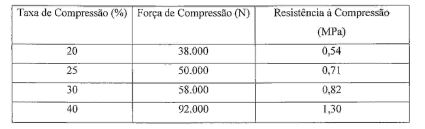
Agregado com fração de vazio nominal de 92.8% (correspondente a uma densidade de180 kg/m3).
Referência Bibliográfica: Matthew Barsotti e outros, relatório publicado em 21 de Janeiro de 2010, intitulado“Developing Improved Civil Aircraft Arresting Systems", no Programa de Pesquisa Cooperativa de Aeroportos, administrado pela Transportation Research Boardda National Academies.,USA.Bibliographic Reference: Matthew Barsotti et al., Report published on January 21, 2010, entitled “Developing Improved Civil Aircraft Arresting Systems", in the Cooperative Airports Research Program, administered by the Transportation Research Board of the National Academies., USA.
Claims (11)
Applications Claiming Priority (5)
| Application Number | Priority Date | Filing Date | Title |
|---|---|---|---|
| US29450410P | 2010-01-13 | 2010-01-13 | |
| GB1000544.5A GB2476944B (en) | 2010-01-13 | 2010-01-13 | Vehicle arresting bed |
| US61/294,504 | 2010-01-13 | ||
| GB1000544.5 | 2010-01-13 | ||
| PCT/NO2011/000015 WO2011087375A1 (en) | 2010-01-13 | 2011-01-13 | Vehicle arresting bed |
Publications (2)
| Publication Number | Publication Date |
|---|---|
| BR112012017231A2 BR112012017231A2 (en) | 2019-12-10 |
| BR112012017231B1 true BR112012017231B1 (en) | 2020-12-15 |
Family
ID=42028322
Family Applications (1)
| Application Number | Title | Priority Date | Filing Date |
|---|---|---|---|
| BR112012017231-0A BR112012017231B1 (en) | 2010-01-13 | 2011-01-13 | VEHICLE RETENTION BED |
Country Status (23)
| Country | Link |
|---|---|
| US (1) | US8579542B2 (en) |
| EP (1) | EP2523857B1 (en) |
| JP (1) | JP6022942B2 (en) |
| KR (1) | KR101866379B1 (en) |
| CN (1) | CN102822057B (en) |
| AU (1) | AU2011205869B2 (en) |
| BR (1) | BR112012017231B1 (en) |
| CA (1) | CA2786477C (en) |
| CY (1) | CY1117807T1 (en) |
| DK (1) | DK2523857T3 (en) |
| EA (1) | EA023395B1 (en) |
| ES (1) | ES2581853T3 (en) |
| GB (1) | GB2476944B (en) |
| HR (1) | HRP20160844T1 (en) |
| HU (1) | HUE028791T2 (en) |
| IN (1) | IN2012DN06458A (en) |
| MX (1) | MX338142B (en) |
| PL (1) | PL2523857T3 (en) |
| PT (1) | PT2523857T (en) |
| RS (1) | RS55041B1 (en) |
| SI (1) | SI2523857T1 (en) |
| SM (1) | SMT201600241B (en) |
| WO (1) | WO2011087375A1 (en) |
Families Citing this family (15)
| Publication number | Priority date | Publication date | Assignee | Title |
|---|---|---|---|---|
| US9376344B2 (en) | 2006-02-17 | 2016-06-28 | Earthstone International, Llc | Foamed glass ceramic composite materials and a method for producing the same |
| US9382671B2 (en) * | 2006-02-17 | 2016-07-05 | Andrew Ungerleider | Foamed glass composite material and a method for using the same |
| US10435177B2 (en) | 2006-02-17 | 2019-10-08 | Earthstone International Llc | Foamed glass composite arrestor beds having predetermined failure modes |
| US9637246B2 (en) | 2006-02-17 | 2017-05-02 | Earthstone International Llc | Foamed glass composite arrestor beds and methods for making and using the same |
| WO2015191162A1 (en) | 2014-06-11 | 2015-12-17 | Earthstone Inernational, Llc | Foamed glass composite material and a method for using the same |
| US8797191B2 (en) * | 2012-07-13 | 2014-08-05 | Honeywell International Inc. | Systems and methods for displaying runway information |
| US9802717B2 (en) * | 2012-09-06 | 2017-10-31 | Engineered Arresting Systems Corporation | Stabilized aggregates and other materials and structures for energy absorption |
| CN103488841B (en) * | 2013-09-27 | 2016-05-04 | 中国民航科学技术研究院 | A kind of method for designing of airfield runway end characteristic material arresting system |
| ES2734297T3 (en) * | 2015-05-18 | 2019-12-05 | Eng Arresting Sys Corp | Suspended layered energy absorbing material for vehicle arrest systems |
| EP3178740B1 (en) * | 2015-12-07 | 2018-07-11 | Airbus Defence and Space GmbH | Landing device for landing a span-wise loaded aircraft |
| CN105503107B (en) * | 2015-12-10 | 2017-11-10 | 朱晓燕 | A kind of calcium carbonate aircraft crosses the border capture material and its preparation technology |
| CN105625126A (en) * | 2016-03-15 | 2016-06-01 | 中国民航科学技术研究院 | Vehicle blocking system based on buffering and energy absorption material |
| US10711407B2 (en) | 2016-06-10 | 2020-07-14 | The Port Authority Of New York And New Jersey | Engineered material arrestor system |
| CN106364690A (en) * | 2016-10-21 | 2017-02-01 | 曾义 | Novel application of rice husk ash to manufacturing of runway arresting system for airplane or high-speed train |
| JP6902805B2 (en) * | 2017-03-03 | 2021-07-14 | ランウェイ セーフ アイピーアール エイビー | Artificial material restraint system and its formation method |
Family Cites Families (15)
| Publication number | Priority date | Publication date | Assignee | Title |
|---|---|---|---|---|
| US3066896A (en) * | 1959-04-27 | 1962-12-04 | Air Logistics Corp | Method and means for decelerating aircraft on runways |
| GB1169415A (en) * | 1967-05-22 | 1969-11-05 | Mini Of Technology | Arresting Means for Vehicles. |
| US3967704A (en) * | 1968-10-07 | 1976-07-06 | British Industrial Plastics Limited | Vehicle decelerating means |
| US4836856A (en) | 1988-02-12 | 1989-06-06 | Domtar, Inc. | Stabilizing road base composition and method for preparing same |
| US5193764A (en) | 1991-10-01 | 1993-03-16 | Manville Corporation | Aircraft arresting system |
| US5902068A (en) * | 1997-02-07 | 1999-05-11 | Datron, Inc. | Vehicle arresting unit fabrication methods |
| US6726400B1 (en) | 1997-02-07 | 2004-04-27 | Engineered Arresting Systems Corporation | Vehicle arresting bed systems |
| US5885025A (en) * | 1997-02-07 | 1999-03-23 | Datron Inc. | Vehicle arresting bed systems |
| AU2006299419B2 (en) * | 2005-10-03 | 2012-03-08 | Engineered Arresting Systems Corporation | Vehicle incursion inhibitors |
| US7695560B1 (en) * | 2005-12-01 | 2010-04-13 | Buarque De Macedo Pedro M | Strong, lower density composite concrete building material with foam glass aggregate |
| CN101016203A (en) * | 2007-01-22 | 2007-08-15 | 桂永全 | Aviation runway bruising type safety barrage block and manufacturing method thereof |
| US8021075B2 (en) * | 2007-04-06 | 2011-09-20 | Engineered Arresting Systems Corporation | Capped and/or beveled jet blast resistant vehicle arresting units, bed and methods |
| CA2593600C (en) * | 2007-07-13 | 2009-10-06 | Anthony G. Warren | Multi-purpose panels with a modular edge |
| US8021174B1 (en) * | 2009-10-05 | 2011-09-20 | StayConnect, LLC | Cord securing cover for an electrical outlet |
| US9802717B2 (en) * | 2012-09-06 | 2017-10-31 | Engineered Arresting Systems Corporation | Stabilized aggregates and other materials and structures for energy absorption |
-
2010
- 2010-01-13 GB GB1000544.5A patent/GB2476944B/en active Active
-
2011
- 2011-01-13 MX MX2012008127A patent/MX338142B/en active IP Right Grant
- 2011-01-13 ES ES11703509.7T patent/ES2581853T3/en active Active
- 2011-01-13 SI SI201130878A patent/SI2523857T1/en unknown
- 2011-01-13 BR BR112012017231-0A patent/BR112012017231B1/en active IP Right Grant
- 2011-01-13 WO PCT/NO2011/000015 patent/WO2011087375A1/en active Application Filing
- 2011-01-13 JP JP2012548910A patent/JP6022942B2/en active Active
- 2011-01-13 PL PL11703509.7T patent/PL2523857T3/en unknown
- 2011-01-13 RS RS20160544A patent/RS55041B1/en unknown
- 2011-01-13 PT PT117035097T patent/PT2523857T/en unknown
- 2011-01-13 CA CA2786477A patent/CA2786477C/en active Active
- 2011-01-13 CN CN201180005963.5A patent/CN102822057B/en active Active
- 2011-01-13 DK DK11703509.7T patent/DK2523857T3/en active
- 2011-01-13 US US13/142,985 patent/US8579542B2/en active Active
- 2011-01-13 AU AU2011205869A patent/AU2011205869B2/en not_active Ceased
- 2011-01-13 EP EP11703509.7A patent/EP2523857B1/en active Active
- 2011-01-13 EA EA201290613A patent/EA023395B1/en not_active IP Right Cessation
- 2011-01-13 HU HUE11703509A patent/HUE028791T2/en unknown
- 2011-01-13 KR KR1020127020223A patent/KR101866379B1/en active IP Right Grant
-
2012
- 2012-07-20 IN IN6458DEN2012 patent/IN2012DN06458A/en unknown
-
2016
- 2016-07-12 CY CY20161100669T patent/CY1117807T1/en unknown
- 2016-07-12 HR HRP20160844TT patent/HRP20160844T1/en unknown
- 2016-07-21 SM SM201600241T patent/SMT201600241B/en unknown
Also Published As
Similar Documents
| Publication | Publication Date | Title |
|---|---|---|
| BR112012017231B1 (en) | VEHICLE RETENTION BED | |
| JP3929077B2 (en) | Airframe restraint unit and manufacturing method thereof | |
| AU2013313272B2 (en) | Stabilized aggregates and other materials and structures for purposes including, but not limited to, energy absorption | |
| ES2734297T3 (en) | Suspended layered energy absorbing material for vehicle arrest systems | |
| NO340074B1 (en) | Locks for vehicle attacks | |
| RU2449084C1 (en) | Drainage system | |
| CN209292872U (en) | A kind of highway bridge pier anti-collision structure | |
| WO2023001431A1 (en) | Engineered material arresting system | |
| Santagata et al. | Performance of new materials for aircraft arrestor beds | |
| CN106381877A (en) | Method for transferring dangerous rock body cut stone on high and steep slope and structure of method | |
| EP3098352A1 (en) | Internal structure of a deformation block, deformation block and deformation system | |
| Amin et al. | Phenolic foams: The insulating materials to reduce the frost penetration, skidding, and flooding risk of road and airfield pavements | |
| San Filippo et al. | Engineered materials arresting system (EMAS): An alternative solution to runway overruns | |
| NO20210933A1 (en) | Engineered Material Arresting System | |
| KR20100122166A (en) | Soft-ground arresting system for aircraft and simulation method for testing of such soft-ground arresting system | |
| Balbo | Feasibility of pervious concrete as engineered material arresting system for airport runway safety areas | |
| CN203742224U (en) | Anti-tilting curbstone for parking space | |
| CZ28616U1 (en) | Deformation block internal structure, deformation block and deformation system |
Legal Events
| Date | Code | Title | Description |
|---|---|---|---|
| B06F | Objections, documents and/or translations needed after an examination request according [chapter 6.6 patent gazette] | ||
| B25A | Requested transfer of rights approved |
Owner name: RUNWAY SAFE IPR AB (SE) |
|
| B06U | Preliminary requirement: requests with searches performed by other patent offices: procedure suspended [chapter 6.21 patent gazette] | ||
| B09A | Decision: intention to grant [chapter 9.1 patent gazette] | ||
| B16A | Patent or certificate of addition of invention granted [chapter 16.1 patent gazette] |
Free format text: PRAZO DE VALIDADE: 20 (VINTE) ANOS CONTADOS A PARTIR DE 13/01/2011, OBSERVADAS AS CONDICOES LEGAIS. |