BR112012015190B1 - apparatus to produce a non-uniform coating on a substrate - Google Patents
apparatus to produce a non-uniform coating on a substrate Download PDFInfo
- Publication number
- BR112012015190B1 BR112012015190B1 BR112012015190-8A BR112012015190A BR112012015190B1 BR 112012015190 B1 BR112012015190 B1 BR 112012015190B1 BR 112012015190 A BR112012015190 A BR 112012015190A BR 112012015190 B1 BR112012015190 B1 BR 112012015190B1
- Authority
- BR
- Brazil
- Prior art keywords
- coating
- cylinder
- fact
- substrate
- needle tubes
- Prior art date
Links
Images
Classifications
-
- B—PERFORMING OPERATIONS; TRANSPORTING
- B05—SPRAYING OR ATOMISING IN GENERAL; APPLYING FLUENT MATERIALS TO SURFACES, IN GENERAL
- B05D—PROCESSES FOR APPLYING FLUENT MATERIALS TO SURFACES, IN GENERAL
- B05D1/00—Processes for applying liquids or other fluent materials
- B05D1/28—Processes for applying liquids or other fluent materials performed by transfer from the surfaces of elements carrying the liquid or other fluent material, e.g. brushes, pads, rollers
-
- B—PERFORMING OPERATIONS; TRANSPORTING
- B05—SPRAYING OR ATOMISING IN GENERAL; APPLYING FLUENT MATERIALS TO SURFACES, IN GENERAL
- B05C—APPARATUS FOR APPLYING FLUENT MATERIALS TO SURFACES, IN GENERAL
- B05C1/00—Apparatus in which liquid or other fluent material is applied to the surface of the work by contact with a member carrying the liquid or other fluent material, e.g. a porous member loaded with a liquid to be applied as a coating
- B05C1/04—Apparatus in which liquid or other fluent material is applied to the surface of the work by contact with a member carrying the liquid or other fluent material, e.g. a porous member loaded with a liquid to be applied as a coating for applying liquid or other fluent material to work of indefinite length
- B05C1/08—Apparatus in which liquid or other fluent material is applied to the surface of the work by contact with a member carrying the liquid or other fluent material, e.g. a porous member loaded with a liquid to be applied as a coating for applying liquid or other fluent material to work of indefinite length using a roller or other rotating member which contacts the work along a generating line
- B05C1/0813—Apparatus in which liquid or other fluent material is applied to the surface of the work by contact with a member carrying the liquid or other fluent material, e.g. a porous member loaded with a liquid to be applied as a coating for applying liquid or other fluent material to work of indefinite length using a roller or other rotating member which contacts the work along a generating line characterised by means for supplying liquid or other fluent material to the roller
-
- B—PERFORMING OPERATIONS; TRANSPORTING
- B05—SPRAYING OR ATOMISING IN GENERAL; APPLYING FLUENT MATERIALS TO SURFACES, IN GENERAL
- B05C—APPARATUS FOR APPLYING FLUENT MATERIALS TO SURFACES, IN GENERAL
- B05C1/00—Apparatus in which liquid or other fluent material is applied to the surface of the work by contact with a member carrying the liquid or other fluent material, e.g. a porous member loaded with a liquid to be applied as a coating
- B05C1/04—Apparatus in which liquid or other fluent material is applied to the surface of the work by contact with a member carrying the liquid or other fluent material, e.g. a porous member loaded with a liquid to be applied as a coating for applying liquid or other fluent material to work of indefinite length
- B05C1/08—Apparatus in which liquid or other fluent material is applied to the surface of the work by contact with a member carrying the liquid or other fluent material, e.g. a porous member loaded with a liquid to be applied as a coating for applying liquid or other fluent material to work of indefinite length using a roller or other rotating member which contacts the work along a generating line
- B05C1/10—Apparatus in which liquid or other fluent material is applied to the surface of the work by contact with a member carrying the liquid or other fluent material, e.g. a porous member loaded with a liquid to be applied as a coating for applying liquid or other fluent material to work of indefinite length using a roller or other rotating member which contacts the work along a generating line the liquid or other fluent material being supplied from inside the roller
-
- B—PERFORMING OPERATIONS; TRANSPORTING
- B05—SPRAYING OR ATOMISING IN GENERAL; APPLYING FLUENT MATERIALS TO SURFACES, IN GENERAL
- B05C—APPARATUS FOR APPLYING FLUENT MATERIALS TO SURFACES, IN GENERAL
- B05C1/00—Apparatus in which liquid or other fluent material is applied to the surface of the work by contact with a member carrying the liquid or other fluent material, e.g. a porous member loaded with a liquid to be applied as a coating
- B05C1/04—Apparatus in which liquid or other fluent material is applied to the surface of the work by contact with a member carrying the liquid or other fluent material, e.g. a porous member loaded with a liquid to be applied as a coating for applying liquid or other fluent material to work of indefinite length
- B05C1/14—Apparatus in which liquid or other fluent material is applied to the surface of the work by contact with a member carrying the liquid or other fluent material, e.g. a porous member loaded with a liquid to be applied as a coating for applying liquid or other fluent material to work of indefinite length using a travelling band
-
- B—PERFORMING OPERATIONS; TRANSPORTING
- B05—SPRAYING OR ATOMISING IN GENERAL; APPLYING FLUENT MATERIALS TO SURFACES, IN GENERAL
- B05C—APPARATUS FOR APPLYING FLUENT MATERIALS TO SURFACES, IN GENERAL
- B05C1/00—Apparatus in which liquid or other fluent material is applied to the surface of the work by contact with a member carrying the liquid or other fluent material, e.g. a porous member loaded with a liquid to be applied as a coating
- B05C1/04—Apparatus in which liquid or other fluent material is applied to the surface of the work by contact with a member carrying the liquid or other fluent material, e.g. a porous member loaded with a liquid to be applied as a coating for applying liquid or other fluent material to work of indefinite length
- B05C1/16—Apparatus in which liquid or other fluent material is applied to the surface of the work by contact with a member carrying the liquid or other fluent material, e.g. a porous member loaded with a liquid to be applied as a coating for applying liquid or other fluent material to work of indefinite length only at particular parts of the work
- B05C1/165—Apparatus in which liquid or other fluent material is applied to the surface of the work by contact with a member carrying the liquid or other fluent material, e.g. a porous member loaded with a liquid to be applied as a coating for applying liquid or other fluent material to work of indefinite length only at particular parts of the work using a roller or other rotating member which contacts the work along a generating line
-
- B—PERFORMING OPERATIONS; TRANSPORTING
- B05—SPRAYING OR ATOMISING IN GENERAL; APPLYING FLUENT MATERIALS TO SURFACES, IN GENERAL
- B05C—APPARATUS FOR APPLYING FLUENT MATERIALS TO SURFACES, IN GENERAL
- B05C9/00—Apparatus or plant for applying liquid or other fluent material to surfaces by means not covered by any preceding group, or in which the means of applying the liquid or other fluent material is not important
- B05C9/06—Apparatus or plant for applying liquid or other fluent material to surfaces by means not covered by any preceding group, or in which the means of applying the liquid or other fluent material is not important for applying two different liquids or other fluent materials, or the same liquid or other fluent material twice, to the same side of the work
-
- B—PERFORMING OPERATIONS; TRANSPORTING
- B05—SPRAYING OR ATOMISING IN GENERAL; APPLYING FLUENT MATERIALS TO SURFACES, IN GENERAL
- B05D—PROCESSES FOR APPLYING FLUENT MATERIALS TO SURFACES, IN GENERAL
- B05D5/00—Processes for applying liquids or other fluent materials to surfaces to obtain special surface effects, finishes or structures
-
- B—PERFORMING OPERATIONS; TRANSPORTING
- B05—SPRAYING OR ATOMISING IN GENERAL; APPLYING FLUENT MATERIALS TO SURFACES, IN GENERAL
- B05D—PROCESSES FOR APPLYING FLUENT MATERIALS TO SURFACES, IN GENERAL
- B05D7/00—Processes, other than flocking, specially adapted for applying liquids or other fluent materials to particular surfaces or for applying particular liquids or other fluent materials
- B05D7/50—Multilayers
- B05D7/52—Two layers
- B05D7/53—Base coat plus clear coat type
- B05D7/538—No curing step for the last layer
- B05D7/5383—No curing step for any layer
- B05D7/5385—No curing step for any layer the two layers being applied simultaneously
-
- C—CHEMISTRY; METALLURGY
- C09—DYES; PAINTS; POLISHES; NATURAL RESINS; ADHESIVES; COMPOSITIONS NOT OTHERWISE PROVIDED FOR; APPLICATIONS OF MATERIALS NOT OTHERWISE PROVIDED FOR
- C09J—ADHESIVES; NON-MECHANICAL ASPECTS OF ADHESIVE PROCESSES IN GENERAL; ADHESIVE PROCESSES NOT PROVIDED FOR ELSEWHERE; USE OF MATERIALS AS ADHESIVES
- C09J7/00—Adhesives in the form of films or foils
- C09J7/40—Adhesives in the form of films or foils characterised by release liners
- C09J7/403—Adhesives in the form of films or foils characterised by release liners characterised by the structure of the release feature
-
- D—TEXTILES; PAPER
- D21—PAPER-MAKING; PRODUCTION OF CELLULOSE
- D21H—PULP COMPOSITIONS; PREPARATION THEREOF NOT COVERED BY SUBCLASSES D21C OR D21D; IMPREGNATING OR COATING OF PAPER; TREATMENT OF FINISHED PAPER NOT COVERED BY CLASS B31 OR SUBCLASS D21G; PAPER NOT OTHERWISE PROVIDED FOR
- D21H23/00—Processes or apparatus for adding material to the pulp or to the paper
- D21H23/02—Processes or apparatus for adding material to the pulp or to the paper characterised by the manner in which substances are added
- D21H23/22—Addition to the formed paper
- D21H23/52—Addition to the formed paper by contacting paper with a device carrying the material
- D21H23/56—Rolls
- D21H23/58—Details thereof, e.g. surface characteristics, peripheral speed
-
- B—PERFORMING OPERATIONS; TRANSPORTING
- B05—SPRAYING OR ATOMISING IN GENERAL; APPLYING FLUENT MATERIALS TO SURFACES, IN GENERAL
- B05C—APPARATUS FOR APPLYING FLUENT MATERIALS TO SURFACES, IN GENERAL
- B05C1/00—Apparatus in which liquid or other fluent material is applied to the surface of the work by contact with a member carrying the liquid or other fluent material, e.g. a porous member loaded with a liquid to be applied as a coating
- B05C1/04—Apparatus in which liquid or other fluent material is applied to the surface of the work by contact with a member carrying the liquid or other fluent material, e.g. a porous member loaded with a liquid to be applied as a coating for applying liquid or other fluent material to work of indefinite length
- B05C1/08—Apparatus in which liquid or other fluent material is applied to the surface of the work by contact with a member carrying the liquid or other fluent material, e.g. a porous member loaded with a liquid to be applied as a coating for applying liquid or other fluent material to work of indefinite length using a roller or other rotating member which contacts the work along a generating line
- B05C1/0826—Apparatus in which liquid or other fluent material is applied to the surface of the work by contact with a member carrying the liquid or other fluent material, e.g. a porous member loaded with a liquid to be applied as a coating for applying liquid or other fluent material to work of indefinite length using a roller or other rotating member which contacts the work along a generating line the work being a web or sheets
- B05C1/0834—Apparatus in which liquid or other fluent material is applied to the surface of the work by contact with a member carrying the liquid or other fluent material, e.g. a porous member loaded with a liquid to be applied as a coating for applying liquid or other fluent material to work of indefinite length using a roller or other rotating member which contacts the work along a generating line the work being a web or sheets the coating roller co-operating with other rollers, e.g. dosing, transfer rollers
-
- B—PERFORMING OPERATIONS; TRANSPORTING
- B05—SPRAYING OR ATOMISING IN GENERAL; APPLYING FLUENT MATERIALS TO SURFACES, IN GENERAL
- B05D—PROCESSES FOR APPLYING FLUENT MATERIALS TO SURFACES, IN GENERAL
- B05D2252/00—Sheets
- B05D2252/02—Sheets of indefinite length
Abstract
MÉTODO E APARELHO PARA PRODUZIR UM REVESTIMENTO NÃO UNIFORME EM UM SUBSTRATO A presente invenção refere-se a um dispositivo de aplicação de revestimento de cilindro que pode ser modificado mediante a adição de um ou mais tubos de agulha que suprem o fluido de revestimento para o dispositivo de aplicação de revestimento de cilindro em locais distintos por toda a face do cilindro de revestimento. Os tubos de agulha suprem uma faixa localizada de material de revestimento sobre o cilindro de revestimento sobreposto na camada de revestimento uniforme já presente sobre a superfície do cilindro de revestimento a partir de um reservatório de revestimento a montante criando um padrão de listras sobre a camada de revestimento uniforme. Mediante a variação das velocidades relativas dos cilindros de revestimento no dispositivo de aplicação de revestimento, a largura da lista pode também ser ajustada.METHOD AND APPARATUS TO PRODUCE A NON-UNIFORM COATING IN A SUBSTRATE The present invention relates to a cylinder coating application device that can be modified by adding one or more needle tubes that supply the coating fluid to the device application of cylinder liner in distinct locations across the face of the liner cylinder. The needle tubes supply a localized strip of coating material over the coating cylinder superimposed on the uniform coating layer already present on the surface of the coating cylinder from an upstream coating reservoir creating a pattern of stripes over the coating layer. uniform coating. By varying the relative speeds of the coating rollers in the coating application device, the width of the list can also be adjusted.
Description
[001]Os dispositivos de aplicação de revestimento de cilindro são comumente usados para revestir substratos com vários compostos de revestimento. Os dispositivos de aplicação de revestimento de cilindro podem aplicar um revestimento total muito uniforme através do uso de um cilindro de revestimento sólido ou um revestimento listrado descontínuo através do uso de um cilindro de revestimento sulcado.[001] The cylinder coating application devices are commonly used to coat substrates with various coating compounds. The cylinder coating application devices can apply a very uniform total coating through the use of a solid coating cylinder or a discontinuous striped coating through the use of a grooved coating cylinder.
[002]O inventor determinou que para algumas aplicações é desejável ter um revestimento uniforme total em um substrato e sobreposto no revestimento uniforme um revestimento não uniforme como uma pluralidade de listras. Tais perfis de revestimento podem ser úteis quando se aplica revestimentos posteriores de baixa adesão à base de água durante a fabricação de notas escritas reposicionáveis adesivamente fixáveis. Posto que as notas reposicionáveis individuais possuem somente uma porção adesiva no topo da nota, um revestimento de baixa adesão ou liberação é somente necessário nessa área distinta. Isso implica no fato de que um método de aplicação de revestimento de listra seria adequada para economizar em custo e em material de revestimento.[002] The inventor determined that for some applications it is desirable to have a full uniform coating on a substrate and a non-uniform coating like a plurality of stripes is superimposed on the uniform coating. Such coating profiles can be useful when applying low-adhesion water-based back coatings during the manufacture of adhesive, repositionable, sticky notes. Since individual repositionable banknotes have only one adhesive portion on top of the banknote, a low-adhesion or release coating is only necessary in that distinct area. This implies that a stripe coating application method would be suitable to save on cost and coating material.
[003]Entretanto, o revestimento de baixa adesão é assentado na superfície de escrita da nota reposicionável. Um revestimento de listra pode ser visualmente detectável, dependendo da cor das notas reposicionáveis, uma vez que somente uma porção da superfície de escrita é revestida. Alternativamente, uma superfície de escrita não uniforme pode ser criadas pelo revestimento de listra. O recebimento de tinta no papel pode ser afetado pela presença ou ausência do revestimento de baixa adesão. Dessa forma, um revestimento de listra pode ser inaceitável para consumidores quando se usa a nota reposicionável. Isso implica no fato de ser requerido um revestimento total de espessura suficiente para atuar como um revestimento de baixa adesão.[003] Meanwhile, the low-adhesion coating is seated on the writing surface of the repositionable banknote. A stripe coating can be visually detectable, depending on the color of the repositionable notes, since only a portion of the writing surface is coated. Alternatively, a non-uniform writing surface can be created by stripe coating. The receipt of ink on the paper can be affected by the presence or absence of the low adhesion coating. Thus, a stripe coating may be unacceptable to consumers when using the repositionable banknote. This implies that a total coating of sufficient thickness is required to act as a low adhesion coating.
[004]A fim de economizar em custos de material de revestimento, seria desejável revestir uma superfície das notas reposicionáveis com um revestimento de baixa adesão total para assegurar que as variações escritas e visuais não sejam evidentes, e com um revestimento de listra em áreas em que um revestimento de liberação adequado é necessário para assegurar a removabilidade de cada nota reposicionável da pilha de notas. Dessa forma, um revestimento não uniforme que tem um peso de primeiro revestimento uniforme mais fino e um segundo revestimento de listras sobre o revestimento fino é desejável. Isso reduz os custos de material em comparação à aplicação de um revestimento mais espesso uniforme sobre toda a superfície.[004] In order to save on coating material costs, it would be desirable to coat a repositionable banknote surface with a low total adhesion coating to ensure that written and visual variations are not evident, and with a stripe coating on areas in that a suitable release liner is required to ensure the removability of each repositionable banknote from the banknote stack. Thus, a non-uniform coating having a thinner uniform first coating weight and a second strip coating on the thin coating is desirable. This reduces material costs compared to applying a thicker uniform coating over the entire surface.
[005]O inventor determinou que tal revestimento pode ser aplicado em uma etapa através da modificação de um dispositivo de aplicação de revestimento de cilindro convencional. Anteriormente, um revestimento não uniforme conforme descrito acima iria requer um processo em duas etapas em um dispositivo de aplicação de revestimento de cilindro: primeiro, aplicação de uma camada de revestimento uniforme com um cilindro sólido no dispositivo de aplicação de revestimento, e em segundo lugar, aplicação do revestimento com padrão de listras sobre a camada uniforme através da substituição do cilindro sólido com um cilindro sulcado e do avanço do substrato através do dispositivo de aplicação de revestimento uma segunda vez. A substituição do processo em duas etapas por um processo em uma etapa reduz significativamente os custos operacionais para produzir as notas reposicionáveis.[005] The inventor has determined that such a coating can be applied in one step by modifying a conventional cylinder coating application device. Previously, a non-uniform coating as described above would require a two-step process on a cylinder coating application device: first, applying a uniform coating layer with a solid cylinder on the coating application device, and secondly , application of the striped pattern coating on the uniform layer by replacing the solid cylinder with a grooved cylinder and by advancing the substrate through the coating application device a second time. Replacing the two-step process with a one-step process significantly reduces operating costs to produce repositionable banknotes.
[006]O inventor determinou que um dispositivo de aplicação de revestimento de cilindro convencional pode ser modificado mediante a adição de um ou mais tubos de agulha que suprem fluido de revestimento para o dispositivo de aplicação de revestimento de cilindro em locais distintos por toda a face do cilindro de revestimento. Os tubos de agulha suprem uma faixa localizada de material de revestimento sobre o cilindro de revestimento sobreposto na camada de revestimento uniforme já presente sobre a superfície do cilindro de revestimento a partir de um reservatório de revestimento a montante criando um padrão de listras sobre a camada de revestimento uniforme. Mediante a variação da velocidade relativa dos cilindros de revestimento no dispositivo de aplicação de revestimento, a largura da listra pode também ser controlada, variando, por meio disso, sua largura com aquela necessária com base na largura da faixa adesiva presente nas notas reposicionáveis. Alternativamente ou em combinação com a variação das velocidades de cilindro, a largura da listra pode também ser variada mediante a variação do fluxo de material de revestimento para os tubos de agulha.[006] The inventor has determined that a conventional cylinder liner can be modified by adding one or more needle tubes that supply liner fluid to the cylinder liner at different locations across the face the coating cylinder. The needle tubes supply a localized strip of coating material over the coating cylinder superimposed on the uniform coating layer already present on the surface of the coating cylinder from an upstream coating reservoir creating a pattern of stripes over the coating layer. uniform coating. By varying the relative speed of the coating rollers in the coating application device, the width of the stripe can also be controlled, thereby varying its width with that required based on the width of the adhesive strip present in the repositionable notes. Alternatively or in combination with varying cylinder speeds, the stripe width can also be varied by varying the flow of coating material into the needle tubes.
[007]Por conseguinte, em uma modalidade, a invenção reside em um método de revestimento de um substrato com um dispositivo de aplicação de revestimento de cilindro que compreende: aplicar um primeiro revestimento uniformemente sobre a face de um cilindro de revestimento; aplicar um segundo revestimento em uma ou mais listras distintas sobre o primeiro revestimento; e transferir os primeiro e segundo revestimentos sobre o substrato.[007] Therefore, in one embodiment, the invention resides in a method of coating a substrate with a cylinder coating application device which comprises: applying a first coating evenly over the face of a coating cylinder; applying a second coat on one or more distinct stripes on the first coat; and transfer the first and second coatings onto the substrate.
[008]Em outra modalidade, a invenção reside em um aparelho de revestimento compreendendo um cilindro de revestimento, um primeiro aplicador de revestimento para aplicar um primeiro revestimento sobre o cilindro de revestimento e um segundo aplicador de revestimento que compreende pelo menos um tubo de agulha para aplicar um segundo revestimento sobre o primeiro revestimento.[008] In another embodiment, the invention resides in a coating apparatus comprising a coating cylinder, a first coating applicator for applying a first coating on the coating cylinder and a second coating applicator comprising at least one needle tube to apply a second coat over the first coat.
[009]Deve ser compreendido pelo versado na técnica que a presente discussão é uma descrição de modalidades exemplificadoras apenas, e não pretende limitar os aspectos mais amplos da presente descrição, cujos aspectos amplos são incorporados na construção exemplificadora.[009] It should be understood by the person skilled in the art that the present discussion is a description of exemplary modalities only, and is not intended to limit the broader aspects of the present description, whose broad aspects are incorporated into the exemplary construction.
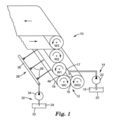
[010]A figura 1 é uma vista em perspectiva de um aparelho para revestimento de um substrato.[010] Figure 1 is a perspective view of an apparatus for coating a substrate.
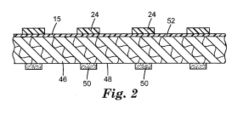
[011]A figura 2 é uma vista de extremidade de direção da máquina de um substrato revestido com listras adesivas em um lado e um revestimento não uniforme de baixa adesão no lado oposto pelo aparelho da figura 1.[011] Figure 2 is an end view of the machine of a substrate coated with adhesive stripes on one side and a non-uniform, low-adhesion coating on the opposite side by the apparatus of figure 1.
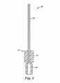
[012]A figura 3 é uma vista em seção transversal de um conjunto de tubo de agulha.[012] Figure 3 is a cross-sectional view of a needle tube assembly.
[013]O uso repetido de caracteres de referência no relatório descritivo e nos desenhos destina-se a representar as características ou elementos iguais ou análogos da revelação.[013] The repeated use of reference characters in the specification and drawings is intended to represent the same or analogous characteristics or elements of the disclosure.
[014]Para uso na presente invenção, as formas das palavras “compreender”, “ter” e “incluir” são legalmente equivalentes e não são limitadoras. Portanto, os elementos, funções, etapas ou limitações adicionais não citados podem estar presentes em adição aos elementos, funções, etapas, ou limitações citados.[014] For use in the present invention, the forms of the words "understand", "have" and "include" are legally equivalent and are not limiting. Therefore, the additional elements, functions, steps or limitations not mentioned may be present in addition to the elements, functions, steps, or limitations mentioned.
[015]Com referência à figura 1, é mostrado um dispositivo de aplicação de revestimento de cilindro 10. O dispositivo de aplicação de revestimento de cilindro ilustrado compreende um dispositivo de aplicação de revestimento de cinco cilindros, mas o método de aplicação de faixas distintas de solução de revestimento à face de um cilindro aplicador em um dispositivo de aplicação de revestimento de cilindro é aplicável a outros dispositivos de aplicação de revestimento de cilindro como dispositivos de aplicação de revestimento de cilindro reversos, dois dispositivos de aplicação de revestimento de cilindro, três dispositivos de aplicação de revestimento de cilindro e quatro dispositivos de aplicação de revestimento de cilindro.[015] With reference to figure 1, a cylinder
[016]O dispositivo de aplicação de revestimento de cilindro ilustrado compreende um primeiro aplicador de revestimento 12 que tem um primeiro suprimento de revestimento 14. O primeiro aplicador de revestimento 12 aplica um primeiro revestimento substancialmente uniforme 15 sobre a face 16 do cilindro W0 e compreende um reservatório de revestimento 17 disposto em uma linha de contato 18 entre o cilindro W0 e o cilindro W00 no dispositivo de aplicação de revestimento de cinco cilindros. O primeiro suprimento de revestimento 14 compreende um primeiro tanque de revestimento 20, uma primeira bomba de revestimento 22 e encanamento para suprir o primeiro revestimento para o reservatório de revestimento. Outros primeiros aplicadores de revestimento 12 para aplicar um primeiro revestimento substancialmente uniforme 15 sobre a face 16 de um cilindro de revestimento podem ser usados como, aplicadores de lâmina raspadora de câmara ou alimentação fechada, uma lâmina raspadora e um reservatório de revestimento atrás da lâmina raspadora, um bocal com fenda longo, imersão do cilindro de revestimento em uma panela de revestimento e um dispositivo de aplicação de revestimento de fonte.[016] The illustrated cylinder coating application device comprises a
[017]Após a aplicação do primeiro revestimento uniforme 15 sobre a face 16 do cilindro W0, um segundo revestimento 24 é aplicado em uma ou mais faixas distintas sobre um cilindro de revestimento por um segundo aplicador de revestimento 26. O segundo aplicador de revestimento 26 compreende um ou mais tubos de agulha 28 localizados em posições transversais à máquina prédeterminadas ao longo da face do cilindro W0 fluidamente conectados a um segundo suprimento de revestimento 30. O segundo suprimento de revestimento 30 pode compreender um segundo tanque de revestimento 32, uma segunda bomba de revestimento 34 e um encanamento que puxa o segundo revestimento 24 a partir do segundo tanque de revestimento 32 e que alimenta uma tubulação 36 à qual os tubos de agulha 28 são fluidamente conectados. Outros segundos aplicadores de revestimento 26 para aplicar faixas distintas de segundo revestimento 24 sobre a face de um cilindro após a aplicação do primeiro revestimento 15 como um cilindro de revestimento sulcado em linha de contato com o cilindro W0 oposto ao cilindro W00 podem ser usados.[017] After the application of the first
[018]Agora com referência à figura 3, um conjunto de tubo de agulha 38 que compreende um tubo de agulha 28 encaixado por pressão em um acoplador 40 é mostrado em seção transversal. O acoplador 40 é tipicamente produzido a partir de náilon ou metais como aço inoxidável ou latão. O acoplador 40 tem uma cabeça hexagonal 42 com um corpo cilíndrico rosqueado 44 e um orifício de folga perfurado através do corpo cilíndrico 44. Um orifício encaixado por pressão é perfurado na cabeça hexagonal 42 e o tubo de agulha 28 do diâmetro apropriado e o comprimento é então encaixado por pressão na cabeça hexagonal 42. O acoplador 40 com o tubo de agulha 28 fixo pode, então, ser rosqueado em um orifício rosqueado na tubulação 36. Tendo em vista que o acoplador 40 pode ser produzido a partir de plástico e pressões operacionais inferiores são usadas na tubulação 36, tipicamente nenhuma gaxeta ou vedante é necessário para impedir vazamentos uma vez que o conjunto de tubo de agulha 38 é apertado sobre a tubulação 36. Os tubos de agulha podem ser usados com outros tipos de acopladores como acopladores de desconexão rápida, acopladores de travamento de torção e acopladores do tipo baioneta se for desejado. Tais acopladores são conhecidos pelo uso quando se supre linhas pneumáticas ou linhas hidráulicas para o maquinário.[018] Now with reference to figure 3, a
[019]Desejavelmente, os tubos de agulha 28 são produzidos a partir de tubo de agulha hipodérmica de aço inoxidável que é fabricado para produzir seringas médicas. Outros materiais de tubo podem ser usados e a seção transversal dos tubos de agulha pode ser circular, quadrada, triangular ou de outro formato geométrico. Em uma modalidade, a seção transversal dos tubos de agulha é circular. O diâmetro interno dos tubos de agulha e o comprimento dos tubos de agulha podem ser selecionados com base na vazão do segundo revestimento 24 que é aplicado, a viscosidade do segundo revestimento, e a pressão operacional desejada do segundo suprimento de revestimento 30. Tipicamente, o diâmetro interno dos tubos de agulha situa-se entre cerca de 0,25 e 2,54 mm (10 mils e cerca de 100 mils), como entre cerca de 1,02 e 1,78 mm (40 mils e cerca de 70 mils). A seleção do diâmetro interno dos tubos de agulha é mais um fator da quantidade do segundo revestimento a ser aplicado e sua viscosidade. Nem todos os tubos de agulha conectado à tubulação precisam ter o mesmo diâmetro interno, então, é possível adicionar mais ou menos segundo revestimento em vários locais de direção transversal à máquina.[019] Desirably,
[020]O comprimento dos tubos de agulha 28 pode ser ajustado para variar a pressão de tubulação necessária para suprir a quantidade desejada do segundo revestimento. Tipicamente, o comprimento dos tubos de agulha situa-se entre cerca de 5,1 e 20,3 cm (2” e cerca de 8”), como entre cerca de 7,6 e 17,8 cm (3” e cerca de 7”). O comprimento suficiente é desejada para produzir um fluxo laminar do segundo revestimento 24 nos tubos de agulha e para produzir uma corrente minimamente divergente do segundo revestimento a partir da saída dos tubos de agulha em oposição a uma aspersão ou gotículas como seria produzido por um cabeçote de aspersão. A corrente pode ser contínua ou intermitente (pulsada) conforme necessário para a aplicação do revestimento.[020] The length of the
[021]Tubos de agulha mais longos podem ser necessários para direcionar o segundo revestimento para uma linha de contato entre dois cilindros de revestimento em oposição à aplicação do segundo revestimento sobre a face de um cilindro de revestimento. Em geral, os tubos de agulha são dimensionados para fornecer um segundo fluxo de revestimento a partir dos tubos de agulha em pressões entre cerca de 34,5 e 137,9 quilopascal (5 psi a cerca de 20 psi); embora, outras pressões possam ser usadas. A uniformidade transversal à máquina intensificada na quantidade do segundo revestimento dispensado por cada tubo de agulha ocorre conforme o comprimento dos tubos de agulha é aumentado e a segunda pressão de suprimento de revestimento é aumentada.[021] Longer needle tubes may be needed to direct the second liner to a contact line between two liners as opposed to applying the second liner to the face of a liner. In general, needle tubes are sized to provide a second coating flow from needle tubes at pressures between about 34.5 and 137.9 kilopascals (5 psi to about 20 psi); although, other pressures can be used. Cross-machine uniformity enhanced in the amount of second coating dispensed by each needle tube occurs as the length of the needle tubes is increased and the second coating supply pressure is increased.
[022]Os tubos de agulha podem ser colocados para impactar o segundo fluxo de revestimento sobre a face do cilindro de revestimento. Tipicamente, tal impacto ocorreria a um ângulo menor que 90 graus em relação a uma tangente extraída da linha para a superfície do cilindro no ponto de impacto do segundo fluxo de revestimento. Em geral, o ângulo de impacto entre o eixo longitudinal dos tubos de agulha e uma tangente extraída da linha para a superfície do cilindro no ponto de impacto situa-se entre cerca de 0 graus a cerca de 60 graus.[022] Needle tubes can be placed to impact the second coating flow on the face of the coating cylinder. Typically, such an impact would occur at an angle less than 90 degrees with respect to a tangent drawn from the line to the surface of the cylinder at the point of impact of the second coating flow. In general, the angle of impact between the longitudinal axis of the needle tubes and a tangent drawn from the line to the surface of the cylinder at the point of impact is between about 0 degrees to about 60 degrees.
[023]Alternativamente, os tubos de agulha podem ser colocados para impactar o segundo fluxo de revestimento em uma linha de contato entre o cilindro de revestimento e um outro cilindro de revestimento como a linha de contato de avanço 46 entre o cilindro W0 e o cilindro W1 conforme mostrado na figura 1 ou a linha de contato de avanço entre o cilindro W1 e o cilindro W2 acima do reservatório de revestimento 17. Através do direcionamento do segundo fluxo de revestimento a partir dos tubos de agulha em uma linha de contato de avanço, a retenção aprimorada do segundo revestimento sobre a face do cilindro de revestimento ocorre.[023] Alternatively, the needle tubes can be placed to impact the second coating flow on a contact line between the coating cylinder and another coating cylinder such as the
[024]Adicionalmente, é possível variar a largura do segundo revestimento que é aplicado ao substrato mediante a variação das velocidades relativas dos cilindros de revestimento que formam a linha de contato de avanço. Em geral, para aumentar a largura do segundo revestimento, a velocidade do cilindro W1 deveria ser diminuída em relação à velocidade do cilindro WO. Para diminuir a largura do segundo revestimento, a velocidade do cilindro W1 deve ser aumentada em relação à velocidade do cilindro WO. O retardamento da velocidade do cilindro a jusante no dispositivo de aplicação de revestimento de cilindro tende a reduzir a taxa de retirada do segundo revestimento e espalhar o segundo revestimento na linha de contato de avanço. Adversamente, o aumento da velocidade do cilindro a jusante no dispositivo de aplicação de revestimento de cilindro tende a aumentar a taxa de retirada do segundo revestimento que reduz seu espalhamento na linha de contato de avanço. É possível desacelerar o cilindro W0 a tal ponto em que as tiras individuais aplicadas ao substrato a partir dos tubos de agulha se consolidem umas com as outras fornecendo um segundo revestimento contínuo no substrato.[024] Additionally, it is possible to vary the width of the second coating that is applied to the substrate by varying the relative speeds of the coating cylinders that form the forward contact line. In general, to increase the width of the second coating, the speed of the cylinder W1 should be decreased in relation to the speed of the WO cylinder. To decrease the width of the second coating, the speed of the cylinder W1 must be increased in relation to the speed of the WO cylinder. The retardation of the speed of the cylinder downstream in the cylinder coating application device tends to reduce the removal rate of the second coating and spread the second coating on the forward contact line. Adversely, increasing the speed of the downstream cylinder in the cylinder coating application device tends to increase the removal rate of the second coating which reduces its spreading in the forward contact line. It is possible to slow down the cylinder W0 to the point where the individual strips applied to the substrate from the needle tubes consolidate with each other providing a second continuous coating on the substrate.
[025]Alternativamente ou em combinação com a variação das velocidades de cilindro de revestimento, a largura do segundo revestimento pode também ser variada mediante a variação da quantidade de segunda solução de revestimento suprida para os tubos de agulha. O suprimento de mais segunda solução de revestimento para os tubos de agulhas irá aumentar a largura do segundo revestimento, enquanto o suprimento de menos segunda solução de revestimento para os tubos de agulha irá diminuir a largura do segundo revestimento.[025] Alternatively or in combination with varying coating cylinder speeds, the width of the second coating can also be varied by varying the amount of second coating solution supplied to the needle tubes. The supply of more second coating solution to the needle tubes will increase the width of the second coating, while the supply of less second coating solution to the needle tubes will decrease the width of the second coating.
[026]O primeiro aplicador de revestimento 12 e o segundo aplicador de revestimento 26 podem aplicar a mesma solução de revestimento ou diferentes soluções de revestimento aos cilindros no dispositivo de aplicação de revestimento de cilindro. Para algumas modalidades, o material de revestimento idêntico pode ser aplicado e a quantidade do primeiro revestimento 15 colocada sobre o substrato pode ser ajustada de uma maneira convencional para o dispositivo de aplicação de revestimento de cilindro e a quantidade de segundo revestimento 24 colocado sobre o substrato pode ser alterada mediante a variação da pressão na tubulação 36 e o tamanho dos tubos de agulha 28. Alternativamente, um material de revestimento similar que tem os mesmos ingredientes ativos, mas um percentual diferente de sólidos pode ser aplicado pelos primeiro e segundo aplicadores de revestimento (12, 26). Por exemplo, um primeiro revestimento com percentual de sólidos baixo pode ser suprido pelo primeiro suprimento de revestimento 14 para fornecer um primeiro revestimento de peso base baixo 15 sobre todo o substrato e um segundo revestimento com percentual de sólidos alto pode ser suprido pelo segundo suprimento de revestimento 30 para fornecer um segundo revestimento de peso base alto 24 no padrão de listra.[026] The
[027]Agora com referência à figura 2, é ilustrado um substrato 46 que tem revestimentos aplicados a ambas as superfícies principais do substrato. Na primeira superfície principal 48 do substrato, uma pluralidade de listras adesivas 50 está presente. As listras adesivas podem ser localizadas em posições ao longo da largura do substrato onde a borda de topo da nota reposicionável finalizada é cortada do substrato. Na segunda superfície principal 52, um revestimento não uniforme está presente, tipicamente, um revestimento de baixa adesão como silicone funcional de mercapto. O revestimento não uniforme que compreende um primeiro revestimento 15 uniformemente aplicado a substancialmente toda a segunda superfície principal 52 e um segundo revestimento não uniforme 24 aplicado em listras sobre o primeiro revestimento. O segundo revestimento é aplicado ao substrato 46 em listras geralmente opostas às listras adesivas 50 na primeira superfície principal 48 pelos tubos de agulha 28. Em geral, a largura do segundo revestimento 24 que é levemente maior que a largura das listras adesivas 50 pode ser controlada pelas velocidades relativas dos cilindros de revestimento em uma linha de contato de avanço conforme anteriormente discutido.[027] Now with reference to figure 2, a
[028]Os objetivos e vantagens dessa descrição são adicionalmente ilustrados pelos exemplos não limitadores a seguir. Os materiais específicos e quantidades dos mesmos recitados nesses exemplos bem como outras condições e detalhes, não devem ser interpretados como limitantes indevidos dessa descrição. Exceto onde especificado em contrário, todas as partes, porcentagens, razões, etc., nos exemplos e no restante do relatório descritivo são expressas em peso.[028] The objectives and advantages of this description are further illustrated by the following non-limiting examples. The specific materials and quantities of them recited in these examples, as well as other conditions and details, should not be interpreted as undue limiting of this description. Unless otherwise specified, all parts, percentages, ratios, etc., in the examples and the rest of the specification are expressed in weight.
[029]O revestimento de substrato foi executado em um dispositivo de aplicação de revestimento de cinco cilindros similar à figura 1 para demonstrar um método de revestimento de cilindro em uma etapa para produzir um substrato revestido que tem um revestimento posterior de baixa adesão (LAB) não uniforme na segunda superfície principal de um substrato de papel conforme ilustrado na figura 3. Um substrato de papel de cor uva foi revestido com o revestimento LAB não uniforme uma vez que as listras desse material de revestimento são frequentemente visíveis em papéis de cor mais escura. À primeira superfície principal do papel um peso de revestimento adesivo de cerca de 7,4 mN (0,75 gsf) foi aplicado em um padrão de listras. O adesivo compreendeu um adesivo compósito de microesfera sensível à pressão que compreende dois ou mais polímeros insolúveis em água que são misturados inteiramente dentro dos limites de microesferas poliméricas conforme descrito na patente U.S. n° 5.824.748 intitulada “Composite Pressure Sensitive Adhesive Microspheres,” de Kesti, et al.[029] The substrate coating was performed on a five-cylinder coating application device similar to figure 1 to demonstrate a one-step cylinder coating method to produce a coated substrate that has a low adhesion back coat (LAB) non-uniform on the second main surface of a paper substrate as shown in figure 3. A grape-colored paper substrate was coated with the non-uniform LAB coating since the streaks of this coating material are often visible on darker colored papers . To the first main surface of the paper an adhesive coating weight of about 7.4 mN (0.75 gsf) was applied in a stripe pattern. The adhesive comprised a pressure sensitive microsphere composite adhesive comprising two or more water-insoluble polymers which are mixed entirely within the limits of polymeric microspheres as described in US Patent No. 5,824,748 entitled “Composite Pressure Sensitive Adhesive Microspheres,” of Kesti, et al.
[030]O revestimento LAB compreendeu 20% de sólidos em solução líquida de um produto de silicone funcional de mercapto número KF2001 disponível comercialmente junto à Shin-Etsu Corporation, Japão. Na segunda superfície principal, aproximadamente 0,20 mN (0,020 gsf) do revestimento LAB foi aplicado nas áreas listradas e aproximadamente 0,10 mN (0,010 gsf) foi revestido em áreas sem as listras. Para alcançar esse perfil de revestimento, o dispositivo de aplicação de revestimento de 5 cilindros foi operado com W0 em aproximadamente 5% da velocidade de manta e com W1 em aproximadamente 70 a 80% da velocidade de manta. A variação da velocidade do cilindro W0 permite que o primeiro revestimento de peso de revestimento de LAB seja ajustado, enquanto o peso de revestimento de LAB dentro da segunda listra de revestimento é ajustado pela vazão de LAB (velocidade da bomba que alimenta os tubos de agulha) e pela largura da listra LAB. O ajuste da velocidade do cilindro W1 permite o espalhamento apropriado do revestimento LAB aplicado pelos tubos de agulha a fim de alcançar uma largura de listra de revestimento LAB levemente maior que a largura da listra adesiva conforme mostrado na figura 2.[030] The LAB coating comprised 20% solids in liquid solution of a mercapto functional silicone product number KF2001 commercially available from Shin-Etsu Corporation, Japan. On the second main surface, approximately 0.20 mN (0.020 gsf) of LAB coating was applied to the striped areas and approximately 0.10 mN (0.010 gsf) was coated on areas without the stripes. To achieve this coating profile, the 5 cylinder coating application device was operated with W0 at approximately 5% of the mat speed and with W1 at approximately 70 to 80% of the mat speed. Variation in cylinder speed W0 allows the first LAB coating weight coating to be adjusted, while the LAB coating weight within the second coating stripe is adjusted by the flow rate of LAB (speed of the pump feeding the needle tubes ) and the width of the LAB stripe. Adjusting the speed of cylinder W1 allows for proper spreading of the LAB coating applied by the needle tubes in order to achieve a LAB coating stripe width slightly greater than the width of the adhesive stripe as shown in figure 2.
[031]O substrato de papel revestido foi convertido em notas reposicionáveis com o uso de métodos de conversão convencionais. Foi observado que o padrão de revestimento LAB não uniforme não produziu listras visíveis na superfície de escrita das notas reposicionáveis uma vez que um revestimento LAB cobriu toda a superfície de escrita da nota reposicionável. Também foi observado que as notas reposicionáveis foram separáveis da pilha de notas e úteis para o propósito ao qual se destina sem aglomeração indevida. A capacidade de escrita das notas reposicionáveis com várias canetas também foi examinada para assegurar que a escrita não pareceu estar diferente entre as áreas sobre a superfície de escrita que tem os pesos de revestimento LAB baixos e altos. Nenhum diferença em capacidade de escrita foi observada. Informações adicionais em substratos revestidos produzidos pelo método e pelo aparelho da invenção são contidas no Pedido de Patente Provisório US N° de Série 61/289186 intitulado “Adhesive Sheet with Differentially Thick Release Coating” depositado em 22 de dezembro de 2009 e com número da Súmula do Advogado 65793US002.[031] The coated paper substrate was converted into repositionable notes using conventional conversion methods. It was observed that the non-uniform LAB coating pattern did not produce visible stripes on the writing surface of the repositionable banknotes since a LAB coating covered the entire writing surface of the repositionable banknote. It was also observed that the repositionable banknotes were separable from the pile of banknotes and useful for the purpose for which it was intended without undue agglomeration. The writing ability of repositionable notes with multiple pens was also examined to ensure that writing did not appear to be different between the areas on the writing surface that have low and high LAB coating weights. No difference in writing ability was observed. Additional information on coated substrates produced by the method and apparatus of the invention is contained in US Provisional Patent Application Serial No. 61/289186 entitled “Adhesive Sheet with Differentially Thick Release Coating” filed on December 22, 2009 and with the Summary Number Attorney 65793US002.
[032]Outras modificações e variações da descrição presente podem ser praticadas por aqueles versados na técnica sem que se desvie do espírito e escopo da presente descrição, que é mais particularmente apresentada nas reivindicações em anexo. Compreende-se que aspectos das várias modalidades podem ser alterados totalmente ou em parte ou podem ser combinados com outros aspectos das várias modalidades. Todas as referências, patentes ou pedidos de patente citados no pedido acima para autorização de patente estão aqui incorporados, a título de referência em sua totalidade de uma maneira consistente. No caso de inconsistências ou contradições entre as porções das referências incorporadas a esse pedido, a informação na descrição precedente deverá controlá-las. A descrição precedente, dada com a finalidade de permitir àquele de habilidade comum na técnica praticar a descrição reivindicada, não deve ser interpretada como limitadora do escopo da descrição, que é definida pelas reivindicações e todos os equivalentes a elas.[032] Other modifications and variations of the present description can be practiced by those skilled in the art without departing from the spirit and scope of the present description, which is more particularly presented in the appended claims. It is understood that aspects of the various modalities can be changed in whole or in part or can be combined with other aspects of the various modalities. All references, patents or patent applications cited in the above application for patent authorization are hereby incorporated by reference in their entirety in a consistent manner. In the event of inconsistencies or contradictions between the portions of the references incorporated in that order, the information in the preceding description should control them. The foregoing description, given for the purpose of allowing one of ordinary skill in the art to practice the claimed description, should not be construed as limiting the scope of the description, which is defined by the claims and all equivalents thereto.
Claims (10)
Applications Claiming Priority (3)
| Application Number | Priority Date | Filing Date | Title |
|---|---|---|---|
| US28917409P | 2009-12-22 | 2009-12-22 | |
| US61/289,174 | 2009-12-22 | ||
| PCT/US2010/060071 WO2011087657A2 (en) | 2009-12-22 | 2010-12-13 | Method and apparatus for producing a non-uniform coating on a substrate |
Publications (2)
| Publication Number | Publication Date |
|---|---|
| BR112012015190A2 BR112012015190A2 (en) | 2016-03-29 |
| BR112012015190B1 true BR112012015190B1 (en) | 2021-01-26 |
Family
ID=44304871
Family Applications (1)
| Application Number | Title | Priority Date | Filing Date |
|---|---|---|---|
| BR112012015190-8A BR112012015190B1 (en) | 2009-12-22 | 2010-12-13 | apparatus to produce a non-uniform coating on a substrate |
Country Status (7)
| Country | Link |
|---|---|
| US (2) | US9266144B2 (en) |
| EP (1) | EP2516070B1 (en) |
| JP (1) | JP5795596B2 (en) |
| KR (1) | KR101779232B1 (en) |
| CN (1) | CN102665935B (en) |
| BR (1) | BR112012015190B1 (en) |
| WO (1) | WO2011087657A2 (en) |
Families Citing this family (14)
| Publication number | Priority date | Publication date | Assignee | Title |
|---|---|---|---|---|
| US9950452B1 (en) | 2002-06-05 | 2018-04-24 | Benjamin V. Booher | Composite friction elements and pultrusion method of making same |
| KR101737159B1 (en) | 2010-06-15 | 2017-05-17 | 쓰리엠 이노베이티브 프로퍼티즈 컴파니 | Distribution manifold with multiple dispensing needles |
| US9884457B1 (en) * | 2010-07-22 | 2018-02-06 | Benjamin V. Booher | Composite friction elements and pultrusion method of making same |
| CA2939923C (en) | 2014-02-18 | 2022-07-05 | 3M Innovative Properties Company | Easy to apply air and water barrier articles |
| CN106029240B (en) | 2014-02-18 | 2020-08-21 | 3M创新有限公司 | Method and apparatus for making articles with non-uniform coatings |
| DE102014207141A1 (en) * | 2014-04-14 | 2015-10-15 | Tesa Se | Coating method with lateral feed |
| KR20170098269A (en) | 2014-12-22 | 2017-08-29 | 쓰리엠 이노베이티브 프로퍼티즈 컴파니 | Air and water barrier goods |
| CN107108140B (en) * | 2014-12-30 | 2020-02-18 | 3M创新有限公司 | Roll formed from microsphere-treated web and method of making same |
| WO2017031359A1 (en) | 2015-08-18 | 2017-02-23 | 3M Innovative Properties Company | Air and water barrier article with porous layer and liner |
| KR20180044950A (en) | 2015-08-26 | 2018-05-03 | 쓰리엠 이노베이티브 프로퍼티즈 캄파니 | Method and apparatus for forming an article having a non-uniformly patterned coating |
| WO2017034879A1 (en) | 2015-08-26 | 2017-03-02 | 3M Innovative Properties Company | Method and apparatus for forming articles with non-uniform discontinuous patterned coatings |
| WO2018156631A1 (en) | 2017-02-23 | 2018-08-30 | 3M Innovative Properties Company | Air and water barrier article including inelastic porous layer |
| EP3917685A4 (en) * | 2019-01-31 | 2023-01-04 | Dow Global Technologies LLC | Paint roller cover for multicolor paint, method of uniformly applying multicolor paint and method of quantifying uniformity of paint application |
| CN115652646B (en) * | 2022-09-26 | 2024-03-29 | 海宁杰盛新材料有限公司 | Polyurethane clothing fabric coating mechanism |
Family Cites Families (52)
| Publication number | Priority date | Publication date | Assignee | Title |
|---|---|---|---|---|
| US3312005A (en) | 1962-10-04 | 1967-04-04 | Dennison Mfg Co | Linerless pressure-sensitive labels |
| US3503782A (en) | 1967-05-29 | 1970-03-31 | Phillips Petroleum Co | Differential release paper |
| US3756195A (en) | 1970-07-16 | 1973-09-04 | Eastman Kodak Co | Apparatus for coating a continuous web |
| US3741786A (en) | 1971-05-28 | 1973-06-26 | Avery Products Corp | Transfer tape having non-contiguous pressure sensitive adhesive patterns |
| DE2253966A1 (en) | 1972-09-27 | 1974-04-11 | Ciba Geigy Ag | DEVICE FOR IMPRAEGNING A TEXTILE TRACK |
| SE430609B (en) * | 1976-12-21 | 1983-11-28 | Sca Development Ab | SET TO CELLULOUS DERIVATIVES MAKE ABSORBING MATERIAL |
| GB1604620A (en) | 1977-11-10 | 1981-12-09 | Britton A | Application of liquid material to webs |
| JPS54143450A (en) | 1978-04-28 | 1979-11-08 | Matsushita Electric Works Ltd | Roll coater |
| US4172655A (en) | 1978-06-26 | 1979-10-30 | Xerox Corporation | Shingle sheet stacking for duplex copying |
| US4273325B1 (en) | 1979-03-08 | 1993-09-07 | Marquip, Inc. | Shingled sheet alignment |
| US4357373A (en) | 1981-04-15 | 1982-11-02 | Armstrong World Industries, Inc. | Apparatus for applying latex coating to moving fabric |
| US4724764B1 (en) * | 1983-05-11 | 1994-09-20 | Baldwin Technology Corp | Dampening system |
| US4768810A (en) | 1986-06-23 | 1988-09-06 | Minnesota Mining And Manufacturing Company | Fanfolded tablet of a web which is separable into sheets each bearing a pressure-sensitive adhesive pattern |
| US5026591A (en) * | 1987-04-21 | 1991-06-25 | W. L. Gore & Associates, Inc. | Coated products and methods for making |
| DE3872920T2 (en) * | 1987-04-21 | 1996-02-08 | Gore & Ass | Coated products. |
| US4814204A (en) | 1987-11-02 | 1989-03-21 | Scott Paper Company | Notched doctored single kiss roll applicator |
| US5154962A (en) | 1988-11-30 | 1992-10-13 | Minnesota Mining And Manufacturing Company | Indicia-receptive low adhesion backsize |
| JPH02174961A (en) | 1988-12-28 | 1990-07-06 | Kawasaki Steel Corp | Roll coater device for steel strip |
| JPH0745023B2 (en) | 1988-12-29 | 1995-05-17 | 石川島播磨重工業株式会社 | Roll coater |
| US4895746A (en) | 1989-03-01 | 1990-01-23 | Minnesota Mining And Manufacturing Company | Stack of pressure sensitive adhesive coated sheets |
| JPH02241575A (en) | 1989-03-15 | 1990-09-26 | Dainippon Screen Mfg Co Ltd | Feeding of coating liquid by roll coater to substrate surface |
| US5032460A (en) | 1989-08-14 | 1991-07-16 | Minnesota Mining And Manufacturing Company | Method of making vinyl-silicone copolymers using mercapto functional silicone chain-transfer agents and release coatings made therewith |
| US5202190A (en) | 1989-08-14 | 1993-04-13 | Minnesota Mining And Manufacturing Company | Method of making vinyl-silicone copolymers using mercapto functional silicone chain-transfer agents and release coatings made therewith |
| US5015500A (en) | 1989-11-16 | 1991-05-14 | Beloit Corporation | Roll coater with perforated deckles |
| JPH0427462A (en) | 1990-05-22 | 1992-01-30 | Kanzaki Paper Mfg Co Ltd | Coating method and applicator |
| FI913739A (en) | 1991-05-09 | 1992-11-10 | Ko Pack Kk | MED LIMFOERSEGLING FOERSETT MAERKNINGSMEDEL |
| JPH0724384A (en) | 1993-07-06 | 1995-01-27 | Sumitomo Metal Ind Ltd | Coating application method and roll coater used in the method |
| JPH07100416A (en) | 1993-10-04 | 1995-04-18 | Hirano Tecseed Co Ltd | Reverse roll coater |
| JPH07156525A (en) * | 1993-12-07 | 1995-06-20 | Dainippon Printing Co Ltd | Pattern forming method |
| JPH086420A (en) | 1994-06-15 | 1996-01-12 | Canon Inc | Fixing device for image forming device |
| US5770267A (en) | 1996-04-05 | 1998-06-23 | J. M. Huber Corporation | Method and apparatus for smoothing substrate surfaces |
| US5824748A (en) | 1996-06-03 | 1998-10-20 | Minnesota Mining And Manufacturing Company | Composite pressure sensitive adhesive microspheres |
| DE29610395U1 (en) * | 1996-06-13 | 1996-08-22 | Voith Sulzer Papiermasch Gmbh | Device for the sequential application of two layers of liquid or pasty media on one side of a running material web |
| US5874144A (en) | 1996-10-23 | 1999-02-23 | Minnesota Mining And Manufacturing Company | Silicon-free copolymer and bleed-through resistant, ink receptive, and adhesive receptive coatings and coated substrates prepared therefrom |
| JPH10128204A (en) | 1996-11-02 | 1998-05-19 | Ricoh Co Ltd | Roll coater |
| FI110274B (en) * | 1996-11-04 | 2002-12-31 | Metso Paper Inc | Method and apparatus for coating a moving cardboard web |
| JP3356262B2 (en) * | 1997-04-09 | 2002-12-16 | ノードソン株式会社 | Adhesive application method and device |
| DE19724648C2 (en) | 1997-06-11 | 1999-06-24 | Zweckform Buero Prod Gmbh | Grid-coated, interlayer-free, self-adhesive fabric |
| AU9372998A (en) | 1997-09-04 | 1999-03-22 | Minnesota Mining And Manufacturing Company | Low adhesion backsize coating compositions |
| US6022050A (en) | 1998-09-02 | 2000-02-08 | Monarch Marking Systems, Inc. | Silicone release coating composition |
| JP2002263540A (en) | 2001-03-14 | 2002-09-17 | Ishikawajima Harima Heavy Ind Co Ltd | Roll coater |
| JP4953182B2 (en) | 2001-08-27 | 2012-06-13 | 大王製紙株式会社 | SAP dispersion slurry coating apparatus and sheet absorbent manufacturing method |
| US7622174B2 (en) | 2001-10-26 | 2009-11-24 | 3M Innovative Properties Company | Tape sheet pads and dispenser and method of dispensing individual tape sheets from such pads |
| US6890112B2 (en) | 2002-10-07 | 2005-05-10 | Paxar Americas, Inc. | Method and system for handling a linerless label web |
| EP1410849A1 (en) * | 2002-10-18 | 2004-04-21 | Solipat Ag | Treatment installation for webs comprising a modular device for applying fluids to webs |
| JP2004167355A (en) | 2002-11-19 | 2004-06-17 | Nec Plasma Display Corp | Roll coater |
| JP2004188331A (en) | 2002-12-12 | 2004-07-08 | Yokoyama Seisakusho:Kk | Kiss type reverse roll coater |
| US7704544B2 (en) * | 2003-10-07 | 2010-04-27 | Advanced Cardiovascular Systems, Inc. | System and method for coating a tubular implantable medical device |
| JP2005195988A (en) * | 2004-01-09 | 2005-07-21 | Mitsui Chemicals Inc | Method and apparatus for manufacturing lithographic printing plate original |
| WO2006008868A1 (en) | 2004-07-22 | 2006-01-26 | Yanmar Co., Ltd. | Engine |
| US8683940B2 (en) | 2006-10-13 | 2014-04-01 | Lg Chem, Ltd. | Apparatus for coating a profile surface, and coating method thereof |
| WO2011087828A1 (en) | 2009-12-22 | 2011-07-21 | 3M Innovative Properties Company | Adhesive sheet with differentially thick release coating |
-
2010
- 2010-12-13 JP JP2012546022A patent/JP5795596B2/en not_active Expired - Fee Related
- 2010-12-13 KR KR1020127019115A patent/KR101779232B1/en active IP Right Grant
- 2010-12-13 BR BR112012015190-8A patent/BR112012015190B1/en not_active IP Right Cessation
- 2010-12-13 US US13/518,747 patent/US9266144B2/en active Active
- 2010-12-13 CN CN201080059239.6A patent/CN102665935B/en not_active Expired - Fee Related
- 2010-12-13 EP EP10843471.3A patent/EP2516070B1/en not_active Not-in-force
- 2010-12-13 WO PCT/US2010/060071 patent/WO2011087657A2/en active Application Filing
-
2016
- 2016-01-12 US US14/993,216 patent/US9950339B2/en active Active
Also Published As
| Publication number | Publication date |
|---|---|
| CN102665935A (en) | 2012-09-12 |
| JP2013514884A (en) | 2013-05-02 |
| KR20120115332A (en) | 2012-10-17 |
| WO2011087657A3 (en) | 2011-11-17 |
| EP2516070B1 (en) | 2018-12-12 |
| EP2516070A2 (en) | 2012-10-31 |
| CN102665935B (en) | 2016-03-30 |
| WO2011087657A2 (en) | 2011-07-21 |
| EP2516070A4 (en) | 2016-11-16 |
| BR112012015190A2 (en) | 2016-03-29 |
| US9266144B2 (en) | 2016-02-23 |
| US20160121362A1 (en) | 2016-05-05 |
| JP5795596B2 (en) | 2015-10-14 |
| KR101779232B1 (en) | 2017-09-18 |
| US20130142953A1 (en) | 2013-06-06 |
| US9950339B2 (en) | 2018-04-24 |
Similar Documents
| Publication | Publication Date | Title |
|---|---|---|
| BR112012015190B1 (en) | apparatus to produce a non-uniform coating on a substrate | |
| US9731314B2 (en) | Coating system with multiple dispensing needles | |
| US20110151169A1 (en) | Adhesive sheet with differentially thick release coating | |
| WO2015177943A1 (en) | Roller transfer application method and application device for hot-melt adhesive | |
| EP2777665A1 (en) | Method of manufacturing a personal hygiene product | |
| AU2011203175B2 (en) | Multi-slot applicator with automatic closing function | |
| JP2010005508A (en) | Slot coating gun | |
| EP2105210A2 (en) | Coating method and coating device | |
| JP3615637B2 (en) | Coating device | |
| JPH0389969A (en) | Coating apparatus | |
| TW200404616A (en) | Die lip for strip coating | |
| EP4212253A1 (en) | Coating device | |
| JP4451028B2 (en) | Coating method and solution casting method | |
| JP2011177688A (en) | Coating system and coating method | |
| HUE029180T2 (en) | Metering coater for highly viscous coating compositions | |
| JP2017104793A (en) | Coating applicator and coating method | |
| JP4314790B2 (en) | Application method | |
| JP2002224606A (en) | Coating apparatus | |
| JP2004216228A (en) | Application tool and applicator | |
| JP2002248402A (en) | Coating apparatus | |
| TW201226513A (en) | Adhesive sheet with differentially thick release coating |
Legal Events
| Date | Code | Title | Description |
|---|---|---|---|
| B06F | Objections, documents and/or translations needed after an examination request according [chapter 6.6 patent gazette] | ||
| B06U | Preliminary requirement: requests with searches performed by other patent offices: procedure suspended [chapter 6.21 patent gazette] | ||
| B06A | Patent application procedure suspended [chapter 6.1 patent gazette] | ||
| B09A | Decision: intention to grant [chapter 9.1 patent gazette] | ||
| B16A | Patent or certificate of addition of invention granted [chapter 16.1 patent gazette] |
Free format text: PRAZO DE VALIDADE: 10 (DEZ) ANOS CONTADOS A PARTIR DE 26/01/2021, OBSERVADAS AS CONDICOES LEGAIS. |
|
| B21F | Lapse acc. art. 78, item iv - on non-payment of the annual fees in time |
Free format text: REFERENTE A 12A ANUIDADE. |
|
| B24J | Lapse because of non-payment of annual fees (definitively: art 78 iv lpi, resolution 113/2013 art. 12) |
Free format text: EM VIRTUDE DA EXTINCAO PUBLICADA NA RPI 2700 DE 04-10-2022 E CONSIDERANDO AUSENCIA DE MANIFESTACAO DENTRO DOS PRAZOS LEGAIS, INFORMO QUE CABE SER MANTIDA A EXTINCAO DA PATENTE E SEUS CERTIFICADOS, CONFORME O DISPOSTO NO ARTIGO 12, DA RESOLUCAO 113/2013. |