BR112012011918B1 - filter cartridge - Google Patents
filter cartridge Download PDFInfo
- Publication number
- BR112012011918B1 BR112012011918B1 BR112012011918-4A BR112012011918A BR112012011918B1 BR 112012011918 B1 BR112012011918 B1 BR 112012011918B1 BR 112012011918 A BR112012011918 A BR 112012011918A BR 112012011918 B1 BR112012011918 B1 BR 112012011918B1
- Authority
- BR
- Brazil
- Prior art keywords
- capillary channels
- filter cartridge
- drip capillary
- drip
- dimension
- Prior art date
Links
- 239000012530 fluid Substances 0.000 claims abstract description 70
- 238000001914 filtration Methods 0.000 claims abstract description 4
- 238000004891 communication Methods 0.000 claims description 5
- XLYOFNOQVPJJNP-UHFFFAOYSA-N water Substances O XLYOFNOQVPJJNP-UHFFFAOYSA-N 0.000 description 28
- 230000003746 surface roughness Effects 0.000 description 8
- 239000002351 wastewater Substances 0.000 description 6
- 230000009471 action Effects 0.000 description 5
- 230000000717 retained effect Effects 0.000 description 5
- 230000003993 interaction Effects 0.000 description 4
- 238000002347 injection Methods 0.000 description 3
- 239000007924 injection Substances 0.000 description 3
- 239000010902 straw Substances 0.000 description 3
- 210000003813 thumb Anatomy 0.000 description 3
- 239000011521 glass Substances 0.000 description 2
- 230000008595 infiltration Effects 0.000 description 2
- 238000001764 infiltration Methods 0.000 description 2
- 239000000463 material Substances 0.000 description 2
- QSHDDOUJBYECFT-UHFFFAOYSA-N mercury Chemical compound [Hg] QSHDDOUJBYECFT-UHFFFAOYSA-N 0.000 description 2
- 229910052753 mercury Inorganic materials 0.000 description 2
- OKTJSMMVPCPJKN-UHFFFAOYSA-N Carbon Chemical compound [C] OKTJSMMVPCPJKN-UHFFFAOYSA-N 0.000 description 1
- 230000004075 alteration Effects 0.000 description 1
- 230000003466 anti-cipated effect Effects 0.000 description 1
- 230000008901 benefit Effects 0.000 description 1
- 229910052799 carbon Inorganic materials 0.000 description 1
- 239000002131 composite material Substances 0.000 description 1
- 238000010276 construction Methods 0.000 description 1
- 230000035622 drinking Effects 0.000 description 1
- 210000003811 finger Anatomy 0.000 description 1
- 239000000796 flavoring agent Substances 0.000 description 1
- 235000019634 flavors Nutrition 0.000 description 1
- 239000012510 hollow fiber Substances 0.000 description 1
- 239000012535 impurity Substances 0.000 description 1
- 238000001746 injection moulding Methods 0.000 description 1
- 230000002452 interceptive effect Effects 0.000 description 1
- 238000003754 machining Methods 0.000 description 1
- 238000004519 manufacturing process Methods 0.000 description 1
- 239000012528 membrane Substances 0.000 description 1
- 238000000034 method Methods 0.000 description 1
- 238000012986 modification Methods 0.000 description 1
- 230000004048 modification Effects 0.000 description 1
- 238000000465 moulding Methods 0.000 description 1
- 230000000149 penetrating effect Effects 0.000 description 1
- 238000001223 reverse osmosis Methods 0.000 description 1
- 238000006467 substitution reaction Methods 0.000 description 1
- 239000008399 tap water Substances 0.000 description 1
- 235000020679 tap water Nutrition 0.000 description 1
Images


Classifications
-
- B—PERFORMING OPERATIONS; TRANSPORTING
- B01—PHYSICAL OR CHEMICAL PROCESSES OR APPARATUS IN GENERAL
- B01D—SEPARATION
- B01D27/00—Cartridge filters of the throw-away type
- B01D27/10—Safety devices, e.g. by-passes
-
- B—PERFORMING OPERATIONS; TRANSPORTING
- B01—PHYSICAL OR CHEMICAL PROCESSES OR APPARATUS IN GENERAL
- B01D—SEPARATION
- B01D2201/00—Details relating to filtering apparatus
- B01D2201/30—Filter housing constructions
- B01D2201/301—Details of removable closures, lids, caps, filter heads
- B01D2201/302—Details of removable closures, lids, caps, filter heads having inlet or outlet ports
-
- B—PERFORMING OPERATIONS; TRANSPORTING
- B01—PHYSICAL OR CHEMICAL PROCESSES OR APPARATUS IN GENERAL
- B01D—SEPARATION
- B01D35/00—Filtering devices having features not specifically covered by groups B01D24/00 - B01D33/00, or for applications not specifically covered by groups B01D24/00 - B01D33/00; Auxiliary devices for filtration; Filter housing constructions
- B01D35/14—Safety devices specially adapted for filtration; Devices for indicating clogging
- B01D35/153—Anti-leakage or anti-return valves
-
- B—PERFORMING OPERATIONS; TRANSPORTING
- B01—PHYSICAL OR CHEMICAL PROCESSES OR APPARATUS IN GENERAL
- B01D—SEPARATION
- B01D35/00—Filtering devices having features not specifically covered by groups B01D24/00 - B01D33/00, or for applications not specifically covered by groups B01D24/00 - B01D33/00; Auxiliary devices for filtration; Filter housing constructions
- B01D35/30—Filter housing constructions
Abstract
CARTUCHO DE FILTRO. A presente invenção refere-se a um cartucho de filtro que compreende um alojamento que compreende uma extremidade terminal, uma extremidade conectiva, e um eixo longitudinal, em que a extremidade conectiva compreende uma entrada de fluido e uma saída de fluido. O cartucho de filtro compreende adicionalmente um meio filtrante disposto dentro do alojamento entre a extremidade terminal e a extremidade conectiva e conecta de modo fluido a entrada de fluido à saída de fluido. Uma da entrada de fluido ou da saída de fluido compreende um ou mais canais capilares antigotejamento, sendo a seção em corte transversal dos canais capilares antigotejamento alongados em pelo menos uma direção.FILTER CARTRIDGE. The present invention relates to a filter cartridge comprising a housing comprising an end end, a connective end, and a longitudinal axis, wherein the connective end comprises a fluid inlet and a fluid outlet. The filter cartridge further comprises filtering means disposed within the housing between the terminal end and the connector end and fluidly connects the fluid inlet to the fluid outlet. One of the fluid inlet or fluid outlet comprises one or more non-drip capillary channels, the cross-section of the non-drip capillary channels being elongated in at least one direction.
Description
[001] Eletrodomésticos como refrigeradores incluem, com frequência, meios para liberar gelo e água gelada para um consumidor. A água liberada, assim como a água usada para fazer o gelo, é, de preferência, filtrada para remover impurezas e aprimorar o sabor. Desse modo, muitos refrigeradores incluem cartuchos de filtro de água descartáveis em uma placa para filtrar água de torneira residual antes da liberação para o consumidor.[001] Appliances such as refrigerators often include means to release ice and chilled water to a consumer. The released water, like the water used to make ice, is preferably filtered to remove impurities and improve flavor. As such, many refrigerators include disposable water filter cartridges on a plate to filter residual tap water prior to consumer release.
[002] Como o espaço é precioso na maioria das residências, é com frequência desejável projetar tais refrigeradores de tal maneira que o espaço consumido como um todo pelo sistema para filtração de água seja minimizado e o cartucho de filtro seja facilmente acessível pelo consumidor para remoção e reposição conveniente. Um projeto que utiliza esses critérios pode resultar no cartucho de filtro sendo posicionado de modo ótimo em diferentes orientações. Por exemplo, o cartucho de filtro pode ser instalado e removido em uma orientação horizontal - isto é, inclinado para um lado.[002] As space is at a premium in most homes, it is often desirable to design such refrigerators in such a way that the space consumed as a whole by the water filtration system is minimized and the filter cartridge is easily accessible by the consumer for removal and convenient replacement. A design that uses these criteria can result in the filter cartridge being optimally positioned in different orientations. For example, the filter cartridge can be installed and removed in a horizontal orientation - that is, tilted to one side.
[003] Quando um cartucho de filtro usado é removido de um refrigerador, o cartucho contém, tipicamente, água residual que pode gotejar ou derramar indesejavelmente a partir do cartucho. Isso é particularmente provável quando o cartucho de filtro é orientado horizontalmente, em que a água residual tende a correr das portas de entrada ou saída no cartucho. Mesmo em refrigeradores em que cartuchos de filtro não são instalados e removidos horizontalmente, o consumidor pode derramar água residual se o cartucho de filtro for acidentalmente inclinado horizontalmente ou mantido de cabeça para baixo.[003] When a used filter cartridge is removed from a cooler, the cartridge typically contains residual water that may drip or spill undesirably from the cartridge. This is particularly likely when the filter cartridge is oriented horizontally, where waste water tends to run out of the inlet or outlet ports on the cartridge. Even in refrigerators where filter cartridges are not installed and removed horizontally, the consumer can spill residual water if the filter cartridge is accidentally tilted horizontally or held upside down.
[004] Existe uma necessidade contínua por cartuchos de filtro que possam reduzir ou evitar o gotejamento ou derramamento quando removido de um eletrodoméstico. Há também uma necessidade por cartuchos de filtro que possam reduzir ou evitar o gotejamento ou derramamento quando removidos de um eletrodoméstico enquanto não aumentam a queda de pressão ao longo do cartucho de filtro. Há também uma necessidade por cartuchos de filtro que possam reduzir ou evitar o gotejamento ou derramamento quando removidos de um eletrodoméstico sem o uso de válvulas ou outras peças móveis. Há também uma necessidade por cartuchos de filtro que possam reduzir ou evitar o gotejamento ou derramamento quando removidos de um eletrodoméstico enquanto são relativamente fáceis de produzir.[004] There is a continuing need for filter cartridges that can reduce or prevent dripping or spillage when removed from an appliance. There is also a need for filter cartridges that can reduce or prevent dripping or spillage when removed from an appliance while not increasing the pressure drop across the filter cartridge. There is also a need for filter cartridges that can reduce or prevent dripping or spillage when removed from an appliance without the use of valves or other moving parts. There is also a need for filter cartridges that can reduce or prevent dripping or spillage when removed from an appliance while being relatively easy to produce.
[005] A presente invenção refere-se em geral a sistemas para filtração de água que compreendem cartuchos de filtro descartáveis. A presente invenção refere-se adicionalmente a cartuchos de filtro que compreendem um recurso antigotejamento. Tais sistemas podem evitar o gotejamento enquanto fornecem uma proporção relativamente maior de área aberta para que a água flua através em comparação a cartuchos de filtro conhecidos. Devido à área relativamente maior aberta para o fluxo de água, cartuchos de filtro de acordo com a presente invenção podem ser fabricados para ter resistência ao fluxo reduzida em comparação a filtros conhecidos. Recursos de antigotejamento de acordo com a presente invenção podem ser mais facilmente fabricados do que recursos de antigotejamento conhecidos.[005] The present invention generally relates to water filtration systems comprising disposable filter cartridges. The present invention further relates to filter cartridges which comprise a non-drip feature. Such systems can prevent dripping while providing a relatively greater proportion of open area for water to flow through compared to known filter cartridges. Due to the relatively larger open area for water flow, filter cartridges in accordance with the present invention can be manufactured to have reduced flow resistance compared to known filters. Non-drip facilities according to the present invention can be manufactured more easily than known anti-drip facilities.
[006] Em uma realização, a presente invenção apresenta um cartucho de filtro que compreende um alojamento que compreende uma extremidade terminal, uma extremidade conectiva, e um eixo longitudinal. Tipicamente, a extremidade conectiva compreende uma entrada de fluido e uma saída de fluido. Um meio filtrante está disposto dentro do alojamento entre a extremidade terminal e a extremidade conectiva. O meio filtrante conecta de modo fluido a entrada de fluido até a saída de fluido, e uma da entrada de fluido ou da saída de fluido compreende um ou mais canais capilares antigotejamento, sendo a seção em corte transversal dos canais capilares antigotejamento alongada em pelo menos uma direção.[006] In one embodiment, the present invention features a filter cartridge comprising a housing comprising an end end, a connective end, and a longitudinal axis. Typically, the connective end comprises a fluid inlet and a fluid outlet. A filter medium is disposed within the housing between the terminal end and the connecting end. The filter media fluidly connects the fluid inlet to the fluid outlet, and one of the fluid inlet or fluid outlet comprises one or more non-drip capillary channels, the cross-section of the non-drip capillary channels being elongated by at least one direction.
[007] Em algumasrealizações, a seção em corte transversal do canal capilar antigotejamento compreende uma dimensão alongada e uma dimensão menor, sendo que a dimensão menor está em uma faixa de cerca de 0,0508 centímetro (cerca de 0,020 polegadas) a cerca de 0,1524 centímetro (cerca de 0,060 polegadas) e a dimensão alongada é maior que cerca de 0,2032 centímetro (cerca de 0,080 polegadas). Em uma realização, a dimensão menor está em uma faixa de cerca de 0,0635 centímetro (cerca de 0,025 polegadas) a cerca de 0,1016 centímetro (cerca de 0,040 polegadas). Em uma realização, a dimensão menor é cerca de 0,0762 centímetro (cerca de 0,030 polegadas).[007] In some embodiments, the cross-section of the non-drip capillary channel comprises an elongated dimension and a smaller dimension, the smaller dimension being in a range from about 0.0508 centimeters (about 0.020 inches) to about 0 .1524 centimeters (about 0.060 inches) and the elongated dimension is greater than about 0.2032 centimeters (about 0.080 inches). In one embodiment, the smallest dimension is in a range from about 0.0635 centimeters (about 0.025 inches) to about 0.1016 centimeters (about 0.040 inches). In one embodiment, the smallest dimension is about 0.0762 centimeters (about 0.030 inches).
[008] Em algumas realizações, a dimensão alongada de um ou mais dos canais capilares antigotejamento compreende uma porção curva. Em algumas realizações, a dimensão alongada de um ou mais dos canais capilares antigotejamento compreende uma linha substancialmente reta. Em algumas realizações, a dimensão alongada de um ou mais dos canais capilares antigotejamento compreende um vértice. Em uma realização, a dimensão menor de um ou mais dos canais capilares antigotejamento é substancialmente constante ao longo da dimensão alongada.[008] In some embodiments, the elongated dimension of one or more of the non-drip capillary channels comprises a curved portion. In some embodiments, the elongated dimension of one or more of the non-drip capillary channels comprises a substantially straight line. In some embodiments, the elongated dimension of one or more of the non-drip capillary channels comprises an apex. In one embodiment, the minor dimension of one or more of the non-drip capillary channels is substantially constant along the elongated dimension.
[009] Em algumas realizações, os canais capilares antigotejamento radiam para fora a partir do eixo longitudinal. Em algumas realizações, os canais capilares antigotejamento são orientados paralelos entre si. Em algumas realizações, os canais capilares antigotejamento são orientados circunferencialmente em torno do eixo longitudinal.[009] In some embodiments, the non-drip capillary channels radiate outward from the longitudinal axis. In some embodiments, the non-drip capillary channels are oriented parallel to each other. In some embodiments, the non-drip capillary channels are oriented circumferentially about the longitudinal axis.
[0010] Em uma realização, a extremidade conectiva compreende um interno coluna vedada ao meio filtrante e um conduto central em comunicação fluida com um núcleo interno aberto do meio filtrante. Em algumas tais realizações, uma luva é formada na extremidade conectiva do alojamento e circunda radialmente a coluna interna. Em algumas realizações, os um ou mais canais capilares antigotejamento são dispostos sobre um flange que se estende em uma região anular entre a coluna interna e a luva, estando os canais capilares antigotejamento em comunicação fluida com uma superfície externa do meio filtrante.[0010] In one embodiment, the connective end comprises an inner column sealed to the filter medium and a central conduit in fluid communication with an open inner core of the filter medium. In some such embodiments, a sleeve is formed on the connecting end of the housing and radially encircles the inner column. In some embodiments, the one or more non-drip capillary channels are disposed over a flange extending in an annular region between the inner column and the sleeve, the non-drip capillary channels being in fluid communication with an outer surface of the filter media.
[0011] Em uma realização, a coluna interna compreende o flange. Em algumas tais realizações, o flange não é afixado à luva. Em algumas realizações, um ou mais dos canais capilares antigotejamento interrompe uma borda externa radial do flange.[0011] In one embodiment, the inner column comprises the flange. In some such embodiments, the flange is not affixed to the sleeve. In some embodiments, one or more of the non-drip capillary channels interrupt a radially outer edge of the flange.
[0012] Em outra realização, a luva compreende o flange. Em algumas tais realizações, o flange não é afixado à coluna interna. Em algumas realizações, um ou mais dos canais capilares antigotejamento interrompe uma borda interna radial do flange.[0012] In another embodiment, the sleeve comprises the flange. In some such embodiments, the flange is not affixed to the inner column. In some embodiments, one or more of the non-drip capillary channels interrupts a radial inner edge of the flange.
[0013] Em algumas realizações, o conduto central forma a saída de fluido e o um ou mais canais capilares antigotejamento formam a entrada de fluido.[0013] In some embodiments, the central conduit forms the fluid outlet and the one or more non-drip capillary channels form the fluid inlet.
[0014] Em uma realização, cada canal capilar antigotejamento compreende pelo menos uma parede lateral de canal, sendo que a altura da aspereza de superfície Ra da pelo menos uma parede lateral de canal é maior que cerca de 1,626 micrômetros (cerca de 64 micropolegadas).[0014] In one embodiment, each non-drip capillary channel comprises at least one channel sidewall, wherein the height of the surface roughness Ra of the at least one channel sidewall is greater than about 1.626 micrometers (about 64 microinches) .
[0015] Em algumas realizações, cada canal capilar antigotejamento compreende adicionalmente uma dimensão de profundidade medida ao longo do eixo longitudinal, sendo que a dimensão de profundidade está em uma faixa de cerca de 0,762 centímetro (cerca de 0,30 polegadas) a cerca de 2,54 centímetros (cerca de 1,0 polegadas). Em uma realização, a dimensão menor está em uma faixa de cerca de 1,016 centímetros (cerca de 0,40 polegadas) a cerca de 1,778 centímetros (cerca de 0,70 polegadas).[0015] In some embodiments, each non-drip capillary channel additionally comprises a depth dimension measured along the longitudinal axis, the depth dimension being in a range from about 0.762 centimeters (about 0.30 inches) to about 2.54 centimeters (about 1.0 inches). In one embodiment, the smallest dimension is in a range from about 1.016 centimeters (about 0.40 inches) to about 1.778 centimeters (about 0.70 inches).
[0016] A presente invenção também fornece um método de formação de um canal capilar antigotejamento que compreende projetar um molde para formar um canal capilar antigotejamento que tem uma parede lateral de canal, especificar uma texturização do molde para conferir uma altura de aspereza de superfície Ra de pelo menos 1,626 micrômetros (64 micropolegadas) para a parede lateral de canal, e injetar um plástico fundido no molde texturizado para formar um canal capilar antigotejamento que tem uma parede lateral de canal com uma altura de aspereza de superfície Ra de pelo menos 1,626 micrômetros (64 micropolegadas).[0016] The present invention also provides a method of forming a non-drip capillary channel comprising designing a mold to form a non-drip capillary channel having a channel sidewall, specifying a texturing of the mold to impart a surface roughness height Ra of at least 1.626 micrometers (64 microinches) for the channel sidewall, and injecting a molten plastic into the textured mold to form a non-drip capillary channel having a channel sidewall with a surface roughness height Ra of at least 1.626 micrometers (64 microinches).
[0017] Estes e outros aspectos da invenção serão aparentes a partir da descrição detalhada abaixo. Entretanto, sob nenhuma hipótese, os sumários acima deverão ser interpretados como limitações do assunto, pois tal assunto é definido única e exclusivamente nas reivindicações em anexo e nas alterações que porventura ocorram durante um eventual litígio.[0017] These and other aspects of the invention will be apparent from the detailed description below. However, under no circumstances shall the above summaries be interpreted as limitations of the matter, as such matter is defined solely and exclusively in the attached claims and in any changes that may occur during any litigation.
[0018] Ao longo do relatório descritivo, é feita referência aos desenhos em anexo, onde a referência numérica igual designa elementos iguais, sendo que:[0018] Throughout the descriptive report, reference is made to the attached drawings, where the equal numerical reference designates like elements, as follows:
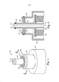
[0019] A figura 1 é uma vista em perspectiva de um cartucho de filtro de acordo com a presente invenção;[0019] Figure 1 is a perspective view of a filter cartridge according to the present invention;
[0020] A figura 2 é uma vista em seção transversal tomada em 2-2 da figura 1 de um cartucho de filtro de acordo com a presente invenção;[0020] Figure 2 is a cross-sectional view taken at 2-2 of Figure 1 of a filter cartridge according to the present invention;
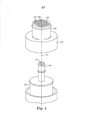
[0021] A figura 3 é uma vista em perspectiva explodida de um cartucho de filtro de acordo com a presente invenção;[0021] Figure 3 is an exploded perspective view of a filter cartridge according to the present invention;
[0022] A figura 4 é uma vista em perspectiva explodida de um cartucho de filtro de acordo com a presente invenção;[0022] Figure 4 is an exploded perspective view of a filter cartridge according to the present invention;
[0023] As figuras 5 a 10 são vistas superiores conforme vistas em 10-10 da figura 2 de cartuchos de filtro de acordo com a presente invenção mostrando várias realizações de canais capilares antigotejamento;[0023] Figures 5 to 10 are top views as seen at 10-10 of Figure 2 of filter cartridges according to the present invention showing various embodiments of non-drip capillary channels;
[0024] A figura 11 é uma vista em seção transversal tomada em 2-2 da figura 1 de um cartucho de filtro de acordo com a presente invenção em uma orientação inclinada com fluido residual dentro;[0024] Figure 11 is a cross-sectional view taken at 2-2 of Figure 1 of a filter cartridge according to the present invention in an inclined orientation with residual fluid inside;
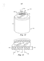
[0025] A figura 12 é uma vista em perspectiva de um cartucho de filtro de acordo com a presente invenção;[0025] Figure 12 is a perspective view of a filter cartridge according to the present invention;
[0026] A figura 13 é uma vista em seção transversal perspectiva tomada em 13-13 da figura 5 de canais capilares antigotejamento exemplificativos de acordo com a presente invenção;[0026] Figure 13 is a perspective cross-sectional view taken at 13-13 of Figure 5 of exemplary non-drip capillary channels according to the present invention;
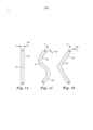
[0027] As figuras 14 a 16 são vistas em planta de seções em corte transversal de canais capilares antigotejamento exemplificativos de acordo com a presente invenção.[0027] Figures 14 to 16 are plan views of cross-sections of exemplary non-drip capillary channels according to the present invention.
[0028] As figuras 1 e 2 retratam um cartucho de filtro exemplificativo 100 de acordo com a presente invenção. Conforme mostrado, o cartucho de filtro 100 compreende um alojamento 102 que compreende uma extremidade terminal 104 (figura 11 ou 12), uma extremidade conectiva 106, e um eixo longitudinal 103. Tipicamente, a extremidade conectiva 106 compreende uma entrada de fluido 110 e uma saída de fluido 112. Um meio filtrante 120 está disposto dentro do alojamento 102 entre a extremidade terminal 104 e a extremidade conectiva 106. O meio filtrante 120 conecta de modo fluido a entrada de fluido 110 até a saída de fluido 112, e uma da entrada de fluido 110 ou da saída de fluido 112 compreende um ou mais canais capilares antigotejamento 130, sendo a seção em corte transversal dos canais capilares antigotejamento 130 alongados em pelo menos uma direção. Embora as figuras 1 e 2 retratem a entrada de fluido 110 como compreendendo um ou mais canais capilares antigotejamento 130, antevê-se que os canais capilares antigotejamento 130 retratados poderiam também formar a saída de fluido 112. Antevê-se também que tanto a entrada de fluido 110 quanto a saída de fluido 112 poderiam compreender um ou mais canais capilares antigotejamento 130.[0028] Figures 1 and 2 depict an
[0029] Os canais capilares antigotejamento 130 podem reduzir ou evitar o gotejamento de fluido residual arrastado dentro de um cartucho de filtro 100 em pelo menos duas formas.The non-drip
[0030] Primeiro, conforme retratado nas figuras 11 e 13, água residual é retirada através de ação capilar nos canais capilares antigotejamento 130. Uma vez que a água residual seja retirada para os canais capilares antigotejamento 130, a mesma é retida através de interação de força entre a água e a parede lateral de canal 132. As forças de atração resultantes dessa ação capilar são fortes o suficiente que, mesmo quando o cartucho de filtro 100 é inclinado para um lado, a força gravitacional sozinha será tipicamente insuficiente para fazer com que a água residual flua por completo através dos canais capilares antigotejamento 130 e causa um gotejamento ou derramamento.[0030] First, as depicted in figures 11 and 13, waste water is removed through capillary action in the non-drip
[0031] A seguir, o fluido é retido na outra porta de fluido (tipicamente, embora nem sempre, a saída de fluido 112, através do conduto central 144) por virtude de um vácuo criado pela água residual que é retida nos canais capilares antigotejamento 130. Essa situação é análoga a um polegar que tampa uma extremidade de um canudo para bebida preenchido com fluido, sendo que o fluido não irá escoar a partir da extremidade livre do canudo visto que a vedação a vácuo criada pelo polegar sobre a extremidade oposta evita a infiltração de ar. Aqui, a água residual retida nos canais capilares antigotejamento 130 tem um papel similar ao polegar no canudo, evitando infiltração de ar que poderia romper o vácuo e liberar o fluido a partir de outra porta de fluido.[0031] The fluid is then retained in the other fluid port (typically, though not always,
[0032] Um fenômeno antigotejamento similar foi anteriormente descrito na patente de propriedade comum n° U.S. 6.632.355 de Fritze ("Fritze ‘355"), estando o teor integral de sua descrição aqui incorporado a título de referência. Fritze ‘355, entretanto, não apresenta o uso de canais capilares antigotejamento, mas, ao invés, relata o uso de orifícios de diâmetro pequeno (isto é, orifícios que têm uma seção circular em corte transversal). De acordo com Fritze ‘355.[0032] A similar anti-drip phenomenon was previously described in commonly owned U.S. Patent No. 6,632,355 to Fritze ("Fritze ‘355"), the entire contents of its description being incorporated herein by reference. Fritze ‘355, however, does not show the use of non-drip capillary channels, but instead reports the use of small diameter holes (ie holes that have a circular cross-section). According to Fritze ‘355.
[0033] Os orifícios de diâmetro pequeno na tampa de extremidade do filtro são dimensionados de modo que a tensão superficial da água evite o transbordamento dos orifícios de diâmetro pequeno quando o conjunto de filtro de água é removido. Isso, por sua vez, cria um vácuo que evita que a água transborde do orifício atravessante na tampa de extremidade de filtro também.[0033] The small diameter holes in the filter end cap are sized so that the surface tension of the water prevents the small diameter holes from overflowing when the water filter assembly is removed. This, in turn, creates a vacuum that prevents water from overflowing from the through hole in the filter end cap as well.
[0034] Entretanto, os orifícios de diâmetro pequeno de Fritze ‘355 podem ter algumas desvantagens em uso. Por exemplo, os orifícios de diâmetro pequeno, tipicamente de cerca de 0,127 cm (0,050 pol) de diâmetro, precisam em geral ser ou usinados (isto é, perfurados) ou moldados com o uso de pinos minúsculos. A usinagem é tipicamente mais custosa e demorada do que uma operação de moldagem, e os pinos minúsculos usados para moldar os orifícios de diâmetro pequeno são muito frágeis e propensos ao dano. Desse modo, ambos os métodos de manufatura podem ser desvantajosos.[0034] However, Fritze ‘355 small diameter holes may have some disadvantages in use. For example, small diameter holes, typically about 0.127 cm (0.050 in) in diameter, usually need to be either machined (ie drilled) or molded using tiny pins. Machining is typically more costly and time-consuming than a molding operation, and the tiny pins used to shape the small diameter holes are very fragile and prone to damage. As such, both manufacturing methods can be disadvantageous.
[0035] Ademais, mesmo se uma pluralidade de orifícios do tipo de Fritze ‘355 sejam formados em uma única peça, a quantidade relativa de área aberta criada para o fluxo de fluidos (área aberta da seção em corte transversal) é significativamente menor do que pode ser criada quando um ou mais canais capilares antigotejamento 130 são empregados.[0035] Furthermore, even if a plurality of Fritze '355 type orifices are formed in a single piece, the relative amount of open area created for fluid flow (cross-sectional open area) is significantly less than it can be created when one or more non-drip
[0036] Por exemplo, presumindo que orifícios de diâmetro pequeno de acordo com Fritze ‘355 que tem um diâmetro D sejam dispostos ao longo de um trajeto de comprimento L com centros espaçados a uma distância de x, a área aberta total para Aorifícios de fluxo de água pode ser calculada como:
[0037] Por outro lado, para um canal capilar antigotejamento 130 que tem uma largura W (isto é, uma dimensão menor 136) e um comprimento de trajeto L (isto é, uma dimensão alongada 134), a área aberta total para o Acanal de fluxo de água pode ser calculado como:

[0038] Deve-se compreender que, na prática, a distância, x, entre os centros dos orifícios de diâmetro pequeno deve ser maior do que D, visto que qualquer valor de x menor resultaria em orifícios adjacentes que interferem um ao outro. Desse modo, embora não prático na realidade, o número de orifícios de diâmetro pequeno em um dado comprimento de trajeto L é teoricamente maximizado quando x = D. Desse modo, a razão entre Acanal e Aorifícios quando Aorifícios é teoricamente maximizada pode ser calculada mediante a substituição de D por x na Eq. 3, resultando em:
[0039] Desse modo, se a largura W do canal capilar antigotejamento 130 é selecionada para ser igual ao diâmetro D de cada orifício, a razão entre Acanal e Aorifícios deve ser sempre maior do que:
[0040] Em conformidade, quando disposto conforme descrito acima, um canal capilar antigotejamento 130 deve ser sempre capaz de criar pelo menos 27% mais área aberta para o fluxo de água do que uma fileira de orifícios de diâmetro pequeno cujo diâmetro é o mesmo que a largura do canal capilar antigotejamento 130. Evidentemente, em aplicação prática, essa razão será tipicamente muito maior pois orifícios de diâmetro pequeno precisarão ser espaçados em intervalos muito maiores, resultando em menos orifícios de diâmetro pequeno por comprimento de unidade. Uma comparação prática é ilustrada abaixo.[0040] Accordingly, when arranged as described above, a non-drip
[0041] Presumindo que orifícios de diâmetro pequeno conforme ensinado por Fritze ‘355 que têm um diâmetro de 0,127 cm (0,050”) cujos centros sejam espaçados a uma distância de dois diâmetros (0,254 cm (0,100”)) por um comprimento de trajeto de 5,08 cm (2”), a área aberta total para Aorifícios de fluxo de água é calculada como:
[0042] Então, presumindo que um canal capilar antigotejamento 130 tenha uma largura de 0,0762 cm (0,030”) e um comprimento de trajeto de 5,08 cm (2”), a área aberta total para Acanal de fluxo de água pode ser calculada como:
[0043] Desse modo, para os exemplos indicados acima, a razão entre Acanal e Aorifícios é:
[0044] Em conformidade, na aplicação prática típica acima, um único canal capilar antigotejamento 130 pode criar cerca de 53% mais área aberta para fluxo de água do que uma típica fileira de orifícios de diâmetro pequeno colocada ao longo do mesmo comprimento, enquanto ainda fornece uma função antigotejamento para um cartucho de filtro 100. Desse modo, como canais capilares antigotejamento 130 podem fornecer uma área aberta relativamente maior para fluxo de água do que uma típica fileira de orifícios de diâmetro pequeno, e como os canais capilares antigotejamento 130 fornecem a entrada de fluido 110 ou saída de fluido 112 de um cartucho de filtro 100, cartuchos de filtro 100 de acordo com a presente invenção podem ser projetados para ter uma queda de pressão como um todo relativamente mais baixa.[0044] Accordingly, in the typical practical application above, a single
[0045] Conforme discutido nos exemplos acima, a largura W pode ser equacionada para a dimensão menor 136 dos um ou mais canais capilares antigotejamento 130, enquanto o comprimento de trajeto L pode ser equacionado para a dimensão alongada 134.[0045] As discussed in the examples above, the width W can be equated to the
[0046] Conforme mostrado nas figuras 2 e 3, a extremidade conectiva 106 pode ser construída a partir de múltiplas peças. Conforme retratado, a extremidade conectiva 106 compreende uma coluna interna 140 colocada ao longo do eixo longitudinal 103 dentro de uma luva 150. Tipicamente, embora não necessariamente, a luva 150 é integralmente formada no alojamento 102. Em algumas realizações, a coluna interna 140 compreende um conduto central 144 em comunicação fluida com um núcleo interno aberto 124 do meio filtrante 120. Conforme mostrado, o conduto central 144 termina na saída de fluido 112. A luva 150 pode compreender uma protuberância cilíndrica a partir do alojamento 102. Em algumas realizações, uma região anular 170 abrange o espaço entre a coluna interna 140 e a luva 150. Em algumas realizações, um ou mais canais capilares antigotejamento 130 são dispostos sobre um flange 160 que abrange a região anular 170.[0046] As shown in figures 2 and 3, the
[0047] O flange 160 pode radiar para dentro a partir da luva 150, conforme mostrado na figura 4, ou pode radiar para fora a partir da coluna interna 140, conforme mostrado na figura 3.[0047]
[0048] A seção em corte transversal de um canal capilar antigotejamento 130 pode ser fechada, conforme mostrado nas figuras 5 a 10, ou um ou mais canais capilares antigotejamento 130 pode interromper uma borda radialmente externa 164 ou borda radialmente interna 168 do flange 160, conforme mostrado nas figuras 3 e 4, respectivamente. Quando um ou mais canais capilares antigotejamento 130 interrompem uma borda radialmente externa ou interna 164 ou 168, a borda radial interrompida pode ou não ser afixada a uma superfície adjacente. Conforme mostrado na figura 2, um flange 160 radia para fora a partir da coluna interna 140 e se ajusta próximo em relação a, mas não é afixado à luva 150. Em tais realizações, pode haver um pequeno vão entre o flange 160 e a luva 150. O pequeno vão pode criar um desvio de fluido, mas é tolerável desde que o vão seja mais restritivo em relação ao fluido do que o um ou mais canais capilares antigotejamento 130. Tal construção pode preservar a funcionalidade antigotejamento do cartucho de filtro 100, tornando ao mesmo tempo a montagem da coluna interna 140 dentro da luva 150 mais rápida e fácil.[0048] The cross-section of a non-drip
[0049] Em realizações em que o flange 160 radia para fora a partir da coluna interna 140, pode ser vantajoso construir os canais capilares antigotejamento 130 de tal maneira que os mesmos interrompam a borda externa radial 164 do flange 160. Por exemplo, quando a coluna interna 140 é moldada por injeção, um molde que divide paralelamente ao eixo longitudinal 103 do cartucho de filtro 100 pode ser mais fácil e menos caro de projetar e construir do que um molde que divide ortogonalmente ao eixo longitudinal 103. Quando o molde se divide paralelamente ao eixo longitudinal 103, "dedos" ou "aletas" que se projetam a partir de cada metade do molde pode formar o um ou mais canais capilares antigotejamento 130 no plástico fundido, enquanto deixa o flange 160 com uma borda externa radial interrompida 164 quando as metades do molde se afastam.[0049] In embodiments where the
[0050] Em algumas realizações, o meio filtrante 120 é afixado na coluna interna 140. Em algumas tais realizações, o conduto central 144 se projeta para dentro do núcleo interno aberto 124 do meio filtrante 120. O meio filtrante 120 pode compreender, por exemplo, um bloco de carbono, um compósito pregueado, um feixe de fibra oca, uma membrana de osmose reversa, ou combinações dos mesmos. Tipicamente, a coluna interna 140 é afixada ao meio filtrante 120 de tal modo a evitar o desvio de fluido entre a coluna interna 140 e o meio filtrante 120. Em tais realizações, um fluido a ser filtrado precisa fluir dentro da entrada de fluido 110, penetrar a superfície externa 128 do meio filtrante 120, fluir através do meio filtrante 120 para dentro do núcleo interno aberto 124, então através do conduto central 144 da coluna interna 140 e, finalmente, para fora da saída de fluido 112.[0050] In some embodiments, the
[0051] Tipicamente, conforme retratado na figura 11, a extremidade terminal 104 é afixada de modo vedável ao alojamento 102 após a coluna interna 140 e o meio filtrante 120 terem sido dispostos dentro do alojamento 102.[0051] Typically, as depicted in Figure 11, the
[0052] As figuras 5 a 10 retratam várias realizações de canais capilares antigotejamento 130 de acordo com a presente invenção, conforme visualizado ao longo do eixo longitudinal 103 de tal maneira que uma vista em planta de cada canal capilar antigotejamento 130 possa ser vista. As setas em seção transversal 10-10 na figura 2 indicam a direção de visualização para as figuras 5 a 10.[0052] Figures 5 to 10 depict various embodiments of non-drip
[0053] As figuras 5 e 10 retratam cartuchos de filtro 100 sendo que canais capilares antigotejamento 130 são orientados paralelos uns aos outros.[0053] Figures 5 and 10 depict
[0054] As figuras 5, 9, e 10 retratam cartuchos de filtro 100 sendo que a dimensão alongada 134 de um ou mais dos canais capilares antigotejamento compreendem uma linha substancialmente reta.[0054] Figures 5, 9, and 10 depict
[0055] As figuras 6 e 7 retratam cartuchos de filtro 100 sendo que a dimensão alongada 134 de um ou mais canais capilares antigotejamento 130 compreendem uma porção curva.[0055] Figures 6 and 7 depict
[0056] A figura 7 retrata um cartucho de filtro 100 sendo que um ou mais canais capilares antigotejamento 130 são orientados circunferencialmente em torno do eixo longitudinal 103.[0056] Figure 7 depicts a
[0057] A figura 8 retrata um cartucho de filtro 100 sendo que a dimensão alongada 134 de um ou mais canais capilares antigotejamento 130 compreendem um vértice.[0057] Figure 8 depicts a
[0058] As figuras 6, 8, e 9 retratam cartuchos de filtro 100 sendo que um ou mais canais capilares antigotejamento 130 radiam para fora a partir do eixo longitudinal 103.[0058] Figures 6, 8, and 9 depict
[0059] Vistas em planta de canais capilares antigotejamento exemplificativos 130, de acordo com a presente invenção, são mostrados em maiores detalhes nas figuras 14 a 16. Em cada uma dessas figuras, a dimensão menor 136 e a dimensão alongada 134 podem ser prontamente vistas. A figura 14 retrata um canal capilar antigotejamento 130 sendo que a dimensão alongada 134 compreende uma linha substancialmente reta. A figura 15 retrata um canal capilar antigotejamento 130 sendo que a dimensão alongada 134 compreende uma porção curva. A figura 16 retrata um canal capilar antigotejamento 130 sendo que a dimensão alongada 134 compreende um vértice. Cada uma das figuras 14 a 16 retrata um canal capilar antigotejamento 130 cuja dimensão menor 136 é substancialmente constante ao longo da dimensão alongada 134. Antevê-se também que a dimensão menor 136 pode aumentar ou diminuir em um ou mais locais ao longo da dimensão alongada 134, desde que a funcionalidade antigotejamento seja mantida. Em algumas realizações, a dimensão menor 136 está na faixa de cerca de 0,0254 cm (0,010”) a cerca de 0,1524 cm (0,060”), incluindo 0,0508 cm (0,020”), 0,0635 cm (0,025”), 0,0762 cm (0,030”), 0,0889 cm (0,035”), 0,1016 cm (0,040”), 0,1143 cm (0,045”), 0,127 cm (0,050”), e 0,1397 cm (0,055”). Em uma realização, a dimensão menor 136 está na faixa de cerca de 0,0635 cm (0,025”) a cerca de 0,1016 cm (0,040”). Deve-se compreender que uma dimensão menor relativamente menor 136 pode tender a aumentar a restrição de fluxo, uma dimensão menor grande demais 136 pode resultar na falha da ação capilar em puxar o fluido na abertura, desse modo fazendo com que a abertura não mais seja um canal capilar antigotejamento 130.[0059] Plan views of exemplary non-drip
[0060] Tipicamente, a dimensão alongada 134 será pelo menos cerca de duas vezes a magnitude da dimensão menor 136, embora um canal capilar antigotejamento 130 possa se beneficiar sempre que a dimensão alongada 134 for maior que a dimensão menor 136. Em algumas realizações, a dimensão alongada 134 é maior que cerca de 0,2032 cm (0,080”). Antevê- se que, para uma dada dimensão menor 136, a dimensão alongada pode ser escolhida para ser tão longa quanto desejada para uma dada aplicação, desde que a abertura continue a funcionar como um canal capilar antigotejamento 130. Deve-se compreender que a dimensão alongada 134 é uma dimensão que é medida ao longo de um trajeto ou trajetória alongada de um canal capilar antigotejamento 130, e não é necessariamente uma linha reta. Por exemplo, na figura 15, a dimensão alongada 134 é medida ao longo de um trajeto alongado que compreende uma porção curva. De modo similar, na figura 16, a dimensão alongada 134 é medida ao longo de um trajeto alongado que compreende uma flexão aguda. Em algumas realizações, como aquelas retratadas nas figuras 2, 3, 4, 5, 7, 10 e 12, a dimensão alongada 134 pode ser diferente para um ou mais canais capilares antigotejamento 130 em um dado cartucho de filtro 100.Typically, the
[0061] A figura 11 retrata uma seção transversal de um cartucho de filtro exemplificador 100, de acordo com a presente invenção, sendo que o cartucho de filtro 100 contém água residual e é inclinado para um lado. Conforme mostrado, água foi puxada através de ação capilar em canais capilares antigotejamento 130 e permanece capturada devido à tensão superficial da água de tal maneira que não seja permitido que o ar infiltre os canais capilares antigotejamento 130. Desse modo, evita-se que água residual flua através de canais capilares antigotejamento 130 e ocasione gotejamento a partir do cartucho de filtro 100. Ao mesmo tempo, evita-se que a água residual no conduto central 144 venha a vazar através da saída de fluido 112 devido à vedação a vácuo criada pela água capturada nos canais capilares antigotejamento 130.[0061] Figure 11 depicts a cross section of an
[0062] A figura 13 é uma vista em seção transversal detalhada tomada em 13-13 da figura 5 que mostra o fluido puxado por ação capilar em canais capilares antigotejamento 130 formado em um flange 160. Conforme retratado, cada canal capilar antigotejamento 130 compreende uma dimensão de profundidade 138, uma dimensão menor 136, uma dimensão alongada 134 (não mostrado), e uma parede lateral de canal 132. Conforme mostrado, o ângulo de contato Φ do fluido em relação à parede lateral de canal 132 é menor que 90 graus (isto é, um ângulo de contato negativo), e o fluido forma, assim, um perfil côncavo em seção transversal. A natureza de interação entre o material da parede lateral de canal 132, o fluido empregado e a atmosfera (tipicamente ar) determina o ângulo de contato e o grau de adesão entre o fluido e a parede lateral de canal 132. Para fins de comparação, em um típico termômetro de tubo de vidro preenchido com mercúrio, o mercúrio e vidro interagem para formar um perfil convexo. Dependendo do fluido de trabalho, o material escolhido para construir os canais capilares antigotejamento 130 devem ser escolhidos para facilitar interações de força apropriadas entre o fluido de trabalho, a parede lateral de canal 132, e o ar de tal maneira que a funcionalidade antigotejamento seja mantida. Tipicamente, embora não necessariamente, o fluido de trabalho é água.[0062] Figure 13 is a detailed cross-sectional view taken at 13-13 of Figure 5 showing the fluid drawn by capillary action in non-drip
[0063] Observou-se que, quando a seção em corte transversal de cada canal capilar antigotejamento 130 é alongada em pelo menos uma direção (em oposição a uma seção transversal circular), a dimensão de profundidade 138 deve ser tipicamente maior que quando um orifício de diâmetro pequeno do tipo Fritze ‘355 é empregado. Como uma dimensão de profundidade maior 138 fornece proporcionalmente mais área superficial de parede lateral de canal 132 para interação com um fluido, o fluido pode ser capilar antigotejamento 130 conforme a dimensão aumentada. Entretanto, tornar a dimensão de demais pode resultar em restrição de fluxo de fluidos e, portanto, maior queda de pressão através de um cartucho de filtro 100. Nesse sentido, a dimensão de profundidade 138 pode ser vantajosamente escolhida numa faixa de cerca de 0,762 centímetro (cerca de 0,30 polegada) a cerca de 2,54 centímetros (cerca de 1,0 polegada), incluindo 2,286 centímetros (0,90 polegada).[0063] It has been observed that when the cross-section of each non-drip
[0064] Observou-se também que uma superfície relativamente mais áspera da parede lateral de canal 132 pode fornecer retenção surpreendentemente melhor de fluido dentro dos canais capilares antigotejamento 130. Por exemplo, flanges de protótipo 160 que compreendem canais capilares antigotejamento 130 produzidos através de estereolitografia (SLA) tiveram superfícies mais ásperas do que aqueles produzidos através de modelagem por injeção com acabamento da superfície de molde típico. Inesperadamente, os protótipos de SLA áspero retiveram fluido melhor do que as peças moldadas por injeção mais polidas. Acredita-se que, como um acabamento de superfície de parede lateral de canal mais áspera 132 pode fornecer mais área superficial de parede lateral de canal 132 para interação com um fluido, o fluido pode ser melhor retido no canal capilar antigotejamento 130 à medida que a aspereza de superfície é aumentada. Uma altura de aspereza de superfície Ra típica para uma peça moldada por injeção pode ser na faixa de cerca de 0,254 micrômetro (cerca de 10 micropolegadas) a cerca de 0,8128 micrômetro (cerca de 32 micropolegadas), conforme determinado de acordo com ASME B46.1. Nesse sentido, a altura de aspereza de superfície Ra da parede lateral de canal 132 pode ser vantajosamente projetada para ser maior que cerca de 1,626 micrômetros (cerca de 64 micropolegadas), incluindo (1.250 micropolegadas), 38,1 micrômetros (1.500 micropolegadas), ou mesmo 50,8 micrômetros (2.000 micropolegadas). Em uma realização, a altura de aspereza de superfície Ra da parede lateral de canal 132 está na faixa de cerca de 22,86 micrômetros (cerca de 900 micropolegadas) a cerca de 40,64 micrômetros (cerca de 1.600 micropolegadas). Valores diferentes de altura de aspereza de superfície Ra foram obtidos ao especificar diferentes acabamentos de superfície ou texturas na peça do molde usado para formar o um ou mais canais capilares antigotejamento 130.It has also been observed that a relatively rougher surface of
[0065] Conforme mostrado na figura 12, antevê-se também que canais capilares antigotejamento 130 podem ser dispostos sobre uma extremidade conectiva 106 de um cartucho de filtro 100 construído conforme mostrado nas figuras 3, 9, e 10 de Fritze ‘355, ou conforme mostrado e descritos nas patentes n° U.S. 7.481.928 de Fritze ("Fritze ‘928"), estando sua descrição aqui incorporada em teor integral a título de referência. Previu-se também que canais capilares antigotejamento 130 podem ser empregados em cartuchos de filtro conforme mostrado e descritos nas patentes n° U.S. 6.949.189 e 7.135.113 de Bassett et al., cujas descrições estão aqui incorporadas em seu teor integral a título de referência.[0065] As shown in figure 12, it is also envisioned that non-drip
[0066] Várias modificações e alterações da invenção serão evidentes aos técnicos no assunto sem que se desvie do escopo e âmbito da invenção. Deve-se compreender que a invenção não se limita às realizações ilustrativas aqui apresentadas.[0066] Various modifications and alterations of the invention will be evident to those skilled in the art without departing from the scope and scope of the invention. It should be understood that the invention is not limited to the illustrative embodiments presented herein.
Claims (11)
Applications Claiming Priority (3)
| Application Number | Priority Date | Filing Date | Title |
|---|---|---|---|
| US26318209P | 2009-11-20 | 2009-11-20 | |
| US61/263,182 | 2009-11-20 | ||
| PCT/US2010/057197 WO2011063100A2 (en) | 2009-11-20 | 2010-11-18 | Filter cartridge with anti-drip feature |
Publications (2)
| Publication Number | Publication Date |
|---|---|
| BR112012011918A2 BR112012011918A2 (en) | 2020-09-08 |
| BR112012011918B1 true BR112012011918B1 (en) | 2021-04-20 |
Family
ID=44060333
Family Applications (1)
| Application Number | Title | Priority Date | Filing Date |
|---|---|---|---|
| BR112012011918-4A BR112012011918B1 (en) | 2009-11-20 | 2010-11-18 | filter cartridge |
Country Status (7)
| Country | Link |
|---|---|
| US (1) | US9011686B2 (en) |
| EP (1) | EP2501455B1 (en) |
| JP (1) | JP5775091B2 (en) |
| KR (1) | KR101746248B1 (en) |
| CN (1) | CN102596356B (en) |
| BR (1) | BR112012011918B1 (en) |
| WO (1) | WO2011063100A2 (en) |
Families Citing this family (13)
| Publication number | Priority date | Publication date | Assignee | Title |
|---|---|---|---|---|
| KR101591007B1 (en) * | 2015-07-29 | 2016-02-02 | 주식회사 마이크로필터 | Filter Cartridge with Parallel Water Path |
| USD792943S1 (en) * | 2016-04-26 | 2017-07-25 | Hong Kong Ecoaqua Co., Limited | Filter unit |
| USD803980S1 (en) * | 2016-05-09 | 2017-11-28 | Hong Kong Ecoaqua Co., Limited | Water filter |
| USD794750S1 (en) * | 2016-05-09 | 2017-08-15 | Hong Kong Ecoaqua Co., Limited | Water filter |
| USD794751S1 (en) * | 2016-05-09 | 2017-08-15 | Hong Kong Ecoaqua Co., Limited | Water filter |
| USD794749S1 (en) * | 2016-05-09 | 2017-08-15 | Hong Kong Ecoaqua Co., Limited | Water filter |
| US10099162B2 (en) * | 2016-08-31 | 2018-10-16 | Haier Us Appliance Solutions, Inc. | Filter cartridge |
| US10272370B2 (en) | 2017-04-21 | 2019-04-30 | Haier Us Appliance Solutions, Inc. | Anti-drip filter assembly |
| US10913020B2 (en) | 2018-05-16 | 2021-02-09 | Haier Us Appliance Solutions, Inc. | Magnetic interface for a water filter assembly |
| US10905989B2 (en) | 2018-05-16 | 2021-02-02 | Haier Us Appliance Solutions, Inc. | Electromagnet interface for a water filter assembly |
| US10603612B2 (en) | 2018-05-16 | 2020-03-31 | Haier US Applicance Solutions, Inc. | Electromagnet interface for a water filter assembly |
| US10946319B2 (en) | 2019-03-27 | 2021-03-16 | Haier Us Appliance Solutions, Inc. | Filter assembly for improved filter cartridge placement and detection in a refrigerator appliance |
| US11504657B2 (en) | 2019-03-27 | 2022-11-22 | Haier Us Appliance Solutions, Inc. | Leak detection assembly for use with a filter assembly for a refrigerator appliance |
Family Cites Families (11)
| Publication number | Priority date | Publication date | Assignee | Title |
|---|---|---|---|---|
| US5681461A (en) | 1996-01-31 | 1997-10-28 | Caterpillar Inc. | Fluid filter having a reusable filter housing and central core and a replaceable coreless filter element |
| US5753117A (en) | 1996-06-05 | 1998-05-19 | Fleetguard, Inc. | Replaceable filter element and snap-on filter lid assembly |
| US6458269B1 (en) | 2000-04-20 | 2002-10-01 | Cuno Incorporated | Keyed filter assembly |
| US6949189B2 (en) | 2000-04-20 | 2005-09-27 | Cuno Incorporated | Keyed filter assembly |
| US6632355B2 (en) * | 2001-07-30 | 2003-10-14 | Pentapure Incorporated | Low spillage replaceable water filter assembly |
| US20030019819A1 (en) | 2001-07-30 | 2003-01-30 | Karl Fritze | Hot disconnect replaceable water filter assembly |
| DE602004023304D1 (en) * | 2003-08-25 | 2009-11-05 | Pall Corp | FILTER DEVICE |
| CN1950137B (en) * | 2004-04-05 | 2013-07-24 | 3M创新有限公司 | Hot disconnect replaceable water filter assembly |
| US7506666B2 (en) * | 2005-04-29 | 2009-03-24 | 3M Innovative Properties Company | Anti-drip ring and drip seal |
| EP1888200A1 (en) | 2005-05-08 | 2008-02-20 | 3M Innovative Properties Company | Filter cartridge and method of construction thereof |
| DE202008004289U1 (en) | 2008-03-27 | 2010-04-08 | Mann+Hummel Gmbh | Filter lock system with bayonet |
-
2010
- 2010-11-18 JP JP2012540051A patent/JP5775091B2/en not_active Expired - Fee Related
- 2010-11-18 BR BR112012011918-4A patent/BR112012011918B1/en active IP Right Grant
- 2010-11-18 EP EP20100784386 patent/EP2501455B1/en active Active
- 2010-11-18 WO PCT/US2010/057197 patent/WO2011063100A2/en active Application Filing
- 2010-11-18 KR KR1020127015851A patent/KR101746248B1/en active IP Right Grant
- 2010-11-18 US US13/510,170 patent/US9011686B2/en active Active
- 2010-11-18 CN CN201080049548.5A patent/CN102596356B/en active Active
Also Published As
| Publication number | Publication date |
|---|---|
| CN102596356B (en) | 2015-01-14 |
| US9011686B2 (en) | 2015-04-21 |
| US20120279916A1 (en) | 2012-11-08 |
| KR101746248B1 (en) | 2017-06-12 |
| WO2011063100A2 (en) | 2011-05-26 |
| WO2011063100A3 (en) | 2011-11-03 |
| JP5775091B2 (en) | 2015-09-09 |
| BR112012011918A2 (en) | 2020-09-08 |
| EP2501455A2 (en) | 2012-09-26 |
| KR20120096006A (en) | 2012-08-29 |
| CN102596356A (en) | 2012-07-18 |
| EP2501455B1 (en) | 2013-11-06 |
| JP2013511388A (en) | 2013-04-04 |
Similar Documents
| Publication | Publication Date | Title |
|---|---|---|
| BR112012011918B1 (en) | filter cartridge | |
| US4201673A (en) | Apparatus for dialysis of solution | |
| BR102013004607A2 (en) | Liquid Fuel Filter Set | |
| JP5327767B2 (en) | Filtration irrigation method, filtration irrigation apparatus and method for manufacturing the same | |
| CN104394966A (en) | Hollow fiber membrane module | |
| CN104203363B (en) | Static filtering sieves | |
| BR112014022656B1 (en) | CARTRIDGE OCA FIBER MEMBRANE MODULE | |
| WO2006072642A1 (en) | Improved self-cleaning filter for agricultural irrigation water | |
| WO2009121306A1 (en) | A drip-irrigation method, a drip-irrigation head, a drip-irrigation device and a making method thereof | |
| CN102164654B (en) | Membrane cartridge | |
| PT1689516E (en) | The separation of solid particles from the liquid in which they are dispersed | |
| KR101287153B1 (en) | Centrifugal oil cleaner | |
| JP2015120149A5 (en) | ||
| KR20180124144A (en) | Use of a filter element for filtering fluid passing through a filter element, a coalescing filter, a compressed air filter system, a filter element and a method for manufacturing a coalescing filter | |
| US20150336811A1 (en) | Particle Separator | |
| JP2002191905A5 (en) | ||
| CN212439555U (en) | Medical suction filter | |
| JP4362432B2 (en) | Hollow fiber type module | |
| JP2015029946A (en) | Filter unit | |
| CN205867846U (en) | Hollow fiber membrane component for air purification | |
| JP2006255261A (en) | Blood treatment equipment | |
| BR102014011983B1 (en) | pressure measuring cell for use in an infusion or injection system | |
| KR101140129B1 (en) | Filter for compressed air | |
| BR102012031135A2 (en) | FILTER CARTRIDGES | |
| WO2016193511A1 (en) | Granular matrix filter |
Legal Events
| Date | Code | Title | Description |
|---|---|---|---|
| B06U | Preliminary requirement: requests with searches performed by other patent offices: procedure suspended [chapter 6.21 patent gazette] | ||
| B06F | Objections, documents and/or translations needed after an examination request according [chapter 6.6 patent gazette] | ||
| B09A | Decision: intention to grant [chapter 9.1 patent gazette] | ||
| B15K | Others concerning applications: alteration of classification |
Free format text: A CLASSIFICACAO ANTERIOR ERA: B01D 35/153 Ipc: B01D 35/153 (2006.01), B01D 35/30 (2006.01) |
|
| B16A | Patent or certificate of addition of invention granted |
Free format text: PRAZO DE VALIDADE: 10 (DEZ) ANOS CONTADOS A PARTIR DE 20/04/2021, OBSERVADAS AS CONDICOES LEGAIS. |