BR102022011880A2 - DISPLAY DEVICE FOR GLASSES FOR DISPLAYING A VIRTUAL IMAGE IN A USER'S FIELD OF VIEW, DISPLAY DEVICE FOR GLASSES OF AUGMENTED REALITY - Google Patents
DISPLAY DEVICE FOR GLASSES FOR DISPLAYING A VIRTUAL IMAGE IN A USER'S FIELD OF VIEW, DISPLAY DEVICE FOR GLASSES OF AUGMENTED REALITY Download PDFInfo
- Publication number
- BR102022011880A2 BR102022011880A2 BR102022011880-9A BR102022011880A BR102022011880A2 BR 102022011880 A2 BR102022011880 A2 BR 102022011880A2 BR 102022011880 A BR102022011880 A BR 102022011880A BR 102022011880 A2 BR102022011880 A2 BR 102022011880A2
- Authority
- BR
- Brazil
- Prior art keywords
- units
- display device
- line
- unit
- glasses
- Prior art date
Links
- 239000011521 glass Substances 0.000 title claims abstract description 49
- 230000003190 augmentative effect Effects 0.000 title description 4
- 230000004438 eyesight Effects 0.000 claims abstract description 6
- 210000001508 eye Anatomy 0.000 description 35
- 230000003287 optical effect Effects 0.000 description 15
- 230000008901 benefit Effects 0.000 description 14
- 210000001747 pupil Anatomy 0.000 description 14
- 230000000694 effects Effects 0.000 description 8
- 230000010363 phase shift Effects 0.000 description 6
- 238000013459 approach Methods 0.000 description 5
- 230000008878 coupling Effects 0.000 description 5
- 238000010168 coupling process Methods 0.000 description 5
- 238000005859 coupling reaction Methods 0.000 description 5
- 238000005516 engineering process Methods 0.000 description 4
- 230000006870 function Effects 0.000 description 4
- 238000000034 method Methods 0.000 description 4
- 230000010355 oscillation Effects 0.000 description 4
- 230000008569 process Effects 0.000 description 4
- 230000001360 synchronised effect Effects 0.000 description 4
- 239000011248 coating agent Substances 0.000 description 3
- 238000000576 coating method Methods 0.000 description 3
- 239000003086 colorant Substances 0.000 description 3
- 238000013461 design Methods 0.000 description 3
- 210000005069 ears Anatomy 0.000 description 3
- 230000003203 everyday effect Effects 0.000 description 3
- 230000008921 facial expression Effects 0.000 description 3
- 210000003128 head Anatomy 0.000 description 3
- 239000000463 material Substances 0.000 description 3
- 230000008447 perception Effects 0.000 description 3
- 230000004913 activation Effects 0.000 description 2
- 230000005540 biological transmission Effects 0.000 description 2
- 238000012937 correction Methods 0.000 description 2
- 230000001419 dependent effect Effects 0.000 description 2
- 238000009826 distribution Methods 0.000 description 2
- 238000003384 imaging method Methods 0.000 description 2
- 238000004519 manufacturing process Methods 0.000 description 2
- 230000007246 mechanism Effects 0.000 description 2
- 235000012771 pancakes Nutrition 0.000 description 2
- 230000003068 static effect Effects 0.000 description 2
- 108010001267 Protein Subunits Proteins 0.000 description 1
- 230000004308 accommodation Effects 0.000 description 1
- 230000015572 biosynthetic process Effects 0.000 description 1
- 210000005252 bulbus oculi Anatomy 0.000 description 1
- 238000004040 coloring Methods 0.000 description 1
- 238000013016 damping Methods 0.000 description 1
- 230000002542 deteriorative effect Effects 0.000 description 1
- 238000011161 development Methods 0.000 description 1
- 239000000203 mixture Substances 0.000 description 1
- 230000007935 neutral effect Effects 0.000 description 1
- 239000008188 pellet Substances 0.000 description 1
- 230000001012 protector Effects 0.000 description 1
- 230000009467 reduction Effects 0.000 description 1
- 230000001105 regulatory effect Effects 0.000 description 1
- 230000000284 resting effect Effects 0.000 description 1
- 238000000926 separation method Methods 0.000 description 1
- 230000003595 spectral effect Effects 0.000 description 1
- 230000002123 temporal effect Effects 0.000 description 1
- 239000012780 transparent material Substances 0.000 description 1
- 230000001960 triggered effect Effects 0.000 description 1
- 238000012795 verification Methods 0.000 description 1
- 230000004584 weight gain Effects 0.000 description 1
- 235000019786 weight gain Nutrition 0.000 description 1
Images


Classifications
-
- G—PHYSICS
- G02—OPTICS
- G02C—SPECTACLES; SUNGLASSES OR GOGGLES INSOFAR AS THEY HAVE THE SAME FEATURES AS SPECTACLES; CONTACT LENSES
- G02C7/00—Optical parts
- G02C7/02—Lenses; Lens systems ; Methods of designing lenses
- G02C7/08—Auxiliary lenses; Arrangements for varying focal length
- G02C7/086—Auxiliary lenses located directly on a main spectacle lens or in the immediate vicinity of main spectacles
-
- H—ELECTRICITY
- H04—ELECTRIC COMMUNICATION TECHNIQUE
- H04N—PICTORIAL COMMUNICATION, e.g. TELEVISION
- H04N13/00—Stereoscopic video systems; Multi-view video systems; Details thereof
- H04N13/30—Image reproducers
- H04N13/346—Image reproducers using prisms or semi-transparent mirrors
-
- G—PHYSICS
- G02—OPTICS
- G02B—OPTICAL ELEMENTS, SYSTEMS OR APPARATUS
- G02B26/00—Optical devices or arrangements for the control of light using movable or deformable optical elements
- G02B26/08—Optical devices or arrangements for the control of light using movable or deformable optical elements for controlling the direction of light
- G02B26/0816—Optical devices or arrangements for the control of light using movable or deformable optical elements for controlling the direction of light by means of one or more reflecting elements
-
- G—PHYSICS
- G02—OPTICS
- G02B—OPTICAL ELEMENTS, SYSTEMS OR APPARATUS
- G02B27/00—Optical systems or apparatus not provided for by any of the groups G02B1/00 - G02B26/00, G02B30/00
- G02B27/0081—Optical systems or apparatus not provided for by any of the groups G02B1/00 - G02B26/00, G02B30/00 with means for altering, e.g. enlarging, the entrance or exit pupil
-
- G—PHYSICS
- G02—OPTICS
- G02B—OPTICAL ELEMENTS, SYSTEMS OR APPARATUS
- G02B27/00—Optical systems or apparatus not provided for by any of the groups G02B1/00 - G02B26/00, G02B30/00
- G02B27/0093—Optical systems or apparatus not provided for by any of the groups G02B1/00 - G02B26/00, G02B30/00 with means for monitoring data relating to the user, e.g. head-tracking, eye-tracking
-
- G—PHYSICS
- G02—OPTICS
- G02B—OPTICAL ELEMENTS, SYSTEMS OR APPARATUS
- G02B27/00—Optical systems or apparatus not provided for by any of the groups G02B1/00 - G02B26/00, G02B30/00
- G02B27/01—Head-up displays
- G02B27/017—Head mounted
- G02B27/0172—Head mounted characterised by optical features
-
- G—PHYSICS
- G02—OPTICS
- G02B—OPTICAL ELEMENTS, SYSTEMS OR APPARATUS
- G02B27/00—Optical systems or apparatus not provided for by any of the groups G02B1/00 - G02B26/00, G02B30/00
- G02B27/02—Viewing or reading apparatus
- G02B27/022—Viewing apparatus
-
- G—PHYSICS
- G02—OPTICS
- G02B—OPTICAL ELEMENTS, SYSTEMS OR APPARATUS
- G02B27/00—Optical systems or apparatus not provided for by any of the groups G02B1/00 - G02B26/00, G02B30/00
- G02B27/10—Beam splitting or combining systems
- G02B27/1073—Beam splitting or combining systems characterized by manufacturing or alignment methods
-
- G—PHYSICS
- G02—OPTICS
- G02B—OPTICAL ELEMENTS, SYSTEMS OR APPARATUS
- G02B27/00—Optical systems or apparatus not provided for by any of the groups G02B1/00 - G02B26/00, G02B30/00
- G02B27/10—Beam splitting or combining systems
- G02B27/108—Beam splitting or combining systems for sampling a portion of a beam or combining a small beam in a larger one, e.g. wherein the area ratio or power ratio of the divided beams significantly differs from unity, without spectral selectivity
-
- G—PHYSICS
- G02—OPTICS
- G02B—OPTICAL ELEMENTS, SYSTEMS OR APPARATUS
- G02B27/00—Optical systems or apparatus not provided for by any of the groups G02B1/00 - G02B26/00, G02B30/00
- G02B27/10—Beam splitting or combining systems
- G02B27/14—Beam splitting or combining systems operating by reflection only
- G02B27/145—Beam splitting or combining systems operating by reflection only having sequential partially reflecting surfaces
-
- G—PHYSICS
- G02—OPTICS
- G02B—OPTICAL ELEMENTS, SYSTEMS OR APPARATUS
- G02B27/00—Optical systems or apparatus not provided for by any of the groups G02B1/00 - G02B26/00, G02B30/00
- G02B27/10—Beam splitting or combining systems
- G02B27/14—Beam splitting or combining systems operating by reflection only
- G02B27/148—Beam splitting or combining systems operating by reflection only including stacked surfaces having at least one double-pass partially reflecting surface
-
- G—PHYSICS
- G02—OPTICS
- G02B—OPTICAL ELEMENTS, SYSTEMS OR APPARATUS
- G02B27/00—Optical systems or apparatus not provided for by any of the groups G02B1/00 - G02B26/00, G02B30/00
- G02B27/28—Optical systems or apparatus not provided for by any of the groups G02B1/00 - G02B26/00, G02B30/00 for polarising
- G02B27/286—Optical systems or apparatus not provided for by any of the groups G02B1/00 - G02B26/00, G02B30/00 for polarising for controlling or changing the state of polarisation, e.g. transforming one polarisation state into another
-
- G—PHYSICS
- G02—OPTICS
- G02B—OPTICAL ELEMENTS, SYSTEMS OR APPARATUS
- G02B30/00—Optical systems or apparatus for producing three-dimensional [3D] effects, e.g. stereoscopic images
- G02B30/20—Optical systems or apparatus for producing three-dimensional [3D] effects, e.g. stereoscopic images by providing first and second parallax images to an observer's left and right eyes
- G02B30/26—Optical systems or apparatus for producing three-dimensional [3D] effects, e.g. stereoscopic images by providing first and second parallax images to an observer's left and right eyes of the autostereoscopic type
-
- G—PHYSICS
- G02—OPTICS
- G02B—OPTICAL ELEMENTS, SYSTEMS OR APPARATUS
- G02B6/00—Light guides; Structural details of arrangements comprising light guides and other optical elements, e.g. couplings
- G02B6/0001—Light guides; Structural details of arrangements comprising light guides and other optical elements, e.g. couplings specially adapted for lighting devices or systems
- G02B6/0011—Light guides; Structural details of arrangements comprising light guides and other optical elements, e.g. couplings specially adapted for lighting devices or systems the light guides being planar or of plate-like form
- G02B6/0013—Means for improving the coupling-in of light from the light source into the light guide
- G02B6/0015—Means for improving the coupling-in of light from the light source into the light guide provided on the surface of the light guide or in the bulk of it
- G02B6/0018—Redirecting means on the surface of the light guide
-
- G—PHYSICS
- G02—OPTICS
- G02B—OPTICAL ELEMENTS, SYSTEMS OR APPARATUS
- G02B6/00—Light guides; Structural details of arrangements comprising light guides and other optical elements, e.g. couplings
- G02B6/0001—Light guides; Structural details of arrangements comprising light guides and other optical elements, e.g. couplings specially adapted for lighting devices or systems
- G02B6/0011—Light guides; Structural details of arrangements comprising light guides and other optical elements, e.g. couplings specially adapted for lighting devices or systems the light guides being planar or of plate-like form
- G02B6/0013—Means for improving the coupling-in of light from the light source into the light guide
- G02B6/0023—Means for improving the coupling-in of light from the light source into the light guide provided by one optical element, or plurality thereof, placed between the light guide and the light source, or around the light source
- G02B6/0028—Light guide, e.g. taper
-
- G—PHYSICS
- G02—OPTICS
- G02B—OPTICAL ELEMENTS, SYSTEMS OR APPARATUS
- G02B6/00—Light guides; Structural details of arrangements comprising light guides and other optical elements, e.g. couplings
- G02B6/0001—Light guides; Structural details of arrangements comprising light guides and other optical elements, e.g. couplings specially adapted for lighting devices or systems
- G02B6/0011—Light guides; Structural details of arrangements comprising light guides and other optical elements, e.g. couplings specially adapted for lighting devices or systems the light guides being planar or of plate-like form
- G02B6/0013—Means for improving the coupling-in of light from the light source into the light guide
- G02B6/0023—Means for improving the coupling-in of light from the light source into the light guide provided by one optical element, or plurality thereof, placed between the light guide and the light source, or around the light source
- G02B6/003—Lens or lenticular sheet or layer
-
- G—PHYSICS
- G02—OPTICS
- G02B—OPTICAL ELEMENTS, SYSTEMS OR APPARATUS
- G02B6/00—Light guides; Structural details of arrangements comprising light guides and other optical elements, e.g. couplings
- G02B6/0001—Light guides; Structural details of arrangements comprising light guides and other optical elements, e.g. couplings specially adapted for lighting devices or systems
- G02B6/0011—Light guides; Structural details of arrangements comprising light guides and other optical elements, e.g. couplings specially adapted for lighting devices or systems the light guides being planar or of plate-like form
- G02B6/0033—Means for improving the coupling-out of light from the light guide
- G02B6/005—Means for improving the coupling-out of light from the light guide provided by one optical element, or plurality thereof, placed on the light output side of the light guide
- G02B6/0055—Reflecting element, sheet or layer
-
- G—PHYSICS
- G02—OPTICS
- G02B—OPTICAL ELEMENTS, SYSTEMS OR APPARATUS
- G02B6/00—Light guides; Structural details of arrangements comprising light guides and other optical elements, e.g. couplings
- G02B6/0001—Light guides; Structural details of arrangements comprising light guides and other optical elements, e.g. couplings specially adapted for lighting devices or systems
- G02B6/0011—Light guides; Structural details of arrangements comprising light guides and other optical elements, e.g. couplings specially adapted for lighting devices or systems the light guides being planar or of plate-like form
- G02B6/0033—Means for improving the coupling-out of light from the light guide
- G02B6/0056—Means for improving the coupling-out of light from the light guide for producing polarisation effects, e.g. by a surface with polarizing properties or by an additional polarizing elements
-
- H—ELECTRICITY
- H04—ELECTRIC COMMUNICATION TECHNIQUE
- H04N—PICTORIAL COMMUNICATION, e.g. TELEVISION
- H04N13/00—Stereoscopic video systems; Multi-view video systems; Details thereof
- H04N13/30—Image reproducers
- H04N13/332—Displays for viewing with the aid of special glasses or head-mounted displays [HMD]
- H04N13/344—Displays for viewing with the aid of special glasses or head-mounted displays [HMD] with head-mounted left-right displays
-
- H—ELECTRICITY
- H04—ELECTRIC COMMUNICATION TECHNIQUE
- H04N—PICTORIAL COMMUNICATION, e.g. TELEVISION
- H04N13/00—Stereoscopic video systems; Multi-view video systems; Details thereof
- H04N13/30—Image reproducers
- H04N13/366—Image reproducers using viewer tracking
- H04N13/371—Image reproducers using viewer tracking for tracking viewers with different interocular distances; for tracking rotational head movements around the vertical axis
-
- G—PHYSICS
- G02—OPTICS
- G02B—OPTICAL ELEMENTS, SYSTEMS OR APPARATUS
- G02B27/00—Optical systems or apparatus not provided for by any of the groups G02B1/00 - G02B26/00, G02B30/00
- G02B27/01—Head-up displays
- G02B27/0101—Head-up displays characterised by optical features
- G02B2027/011—Head-up displays characterised by optical features comprising device for correcting geometrical aberrations, distortion
-
- G—PHYSICS
- G02—OPTICS
- G02B—OPTICAL ELEMENTS, SYSTEMS OR APPARATUS
- G02B27/00—Optical systems or apparatus not provided for by any of the groups G02B1/00 - G02B26/00, G02B30/00
- G02B27/01—Head-up displays
- G02B27/0101—Head-up displays characterised by optical features
- G02B2027/0112—Head-up displays characterised by optical features comprising device for genereting colour display
- G02B2027/0116—Head-up displays characterised by optical features comprising device for genereting colour display comprising devices for correcting chromatic aberration
-
- G—PHYSICS
- G02—OPTICS
- G02B—OPTICAL ELEMENTS, SYSTEMS OR APPARATUS
- G02B27/00—Optical systems or apparatus not provided for by any of the groups G02B1/00 - G02B26/00, G02B30/00
- G02B27/01—Head-up displays
- G02B27/0101—Head-up displays characterised by optical features
- G02B2027/0123—Head-up displays characterised by optical features comprising devices increasing the field of view
- G02B2027/0125—Field-of-view increase by wavefront division
-
- G—PHYSICS
- G02—OPTICS
- G02B—OPTICAL ELEMENTS, SYSTEMS OR APPARATUS
- G02B27/00—Optical systems or apparatus not provided for by any of the groups G02B1/00 - G02B26/00, G02B30/00
- G02B27/01—Head-up displays
- G02B27/0101—Head-up displays characterised by optical features
- G02B2027/013—Head-up displays characterised by optical features comprising a combiner of particular shape, e.g. curvature
-
- G—PHYSICS
- G02—OPTICS
- G02B—OPTICAL ELEMENTS, SYSTEMS OR APPARATUS
- G02B27/00—Optical systems or apparatus not provided for by any of the groups G02B1/00 - G02B26/00, G02B30/00
- G02B27/01—Head-up displays
- G02B27/017—Head mounted
- G02B27/0172—Head mounted characterised by optical features
- G02B2027/0174—Head mounted characterised by optical features holographic
-
- G—PHYSICS
- G02—OPTICS
- G02B—OPTICAL ELEMENTS, SYSTEMS OR APPARATUS
- G02B27/00—Optical systems or apparatus not provided for by any of the groups G02B1/00 - G02B26/00, G02B30/00
- G02B27/01—Head-up displays
- G02B27/017—Head mounted
- G02B2027/0178—Eyeglass type
-
- G—PHYSICS
- G02—OPTICS
- G02B—OPTICAL ELEMENTS, SYSTEMS OR APPARATUS
- G02B27/00—Optical systems or apparatus not provided for by any of the groups G02B1/00 - G02B26/00, G02B30/00
- G02B27/01—Head-up displays
- G02B27/0179—Display position adjusting means not related to the information to be displayed
- G02B2027/0187—Display position adjusting means not related to the information to be displayed slaved to motion of at least a part of the body of the user, e.g. head, eye
-
- G—PHYSICS
- G02—OPTICS
- G02B—OPTICAL ELEMENTS, SYSTEMS OR APPARATUS
- G02B27/00—Optical systems or apparatus not provided for by any of the groups G02B1/00 - G02B26/00, G02B30/00
- G02B27/01—Head-up displays
- G02B27/0101—Head-up displays characterised by optical features
-
- G—PHYSICS
- G02—OPTICS
- G02B—OPTICAL ELEMENTS, SYSTEMS OR APPARATUS
- G02B27/00—Optical systems or apparatus not provided for by any of the groups G02B1/00 - G02B26/00, G02B30/00
- G02B27/10—Beam splitting or combining systems
-
- G—PHYSICS
- G02—OPTICS
- G02C—SPECTACLES; SUNGLASSES OR GOGGLES INSOFAR AS THEY HAVE THE SAME FEATURES AS SPECTACLES; CONTACT LENSES
- G02C7/00—Optical parts
- G02C7/14—Mirrors; Prisms
-
- H—ELECTRICITY
- H04—ELECTRIC COMMUNICATION TECHNIQUE
- H04N—PICTORIAL COMMUNICATION, e.g. TELEVISION
- H04N13/00—Stereoscopic video systems; Multi-view video systems; Details thereof
- H04N13/30—Image reproducers
- H04N13/365—Image reproducers using digital micromirror devices [DMD]
Abstract
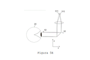
A invenção se refere a um dispositivo de exibição para óculos (0) para exibição de uma imagem virtual no campo de visão de um usuário, com uma unidade de armação (17) ;uma unidade de tela linha por linha (29) fixada à unidade de armação (17) para irradiar uma luz como informação de imagem gerada por computador em uma primeira direção (-z); pelo menos duas unidades divisoras de feixe parcialmente transparentes (10) fixadas à unidade de armação (17), que são projetadas para serem operadas como unidades de varredura com uma frequência de varredura uniformemente fixa, para desviar a luz irradiada pela unidade de tela (29) na primeira direção (-z) para uma segunda faixa direcional (-x), que corresponde ao campo de visão do usuário quando o dispositivo de exibição de óculos (0) é usado de acordo com as especificações; para fornecer um dispositivo de exibição para óculos para exibição (0), uns óculos AR, por meio do qual a imagem virtual pode ser exibida em uma subárea tão grande quanto possível do campo de visão e cujo fator de forma corresponda o mais próximo possível ao de uns óculos comuns.
Description
[0001] A invenção se refere a um dispositivo de exibição para óculos para exibir uma imagem virtual no campo de visão de um usuário, um dispositivo de exibição para óculos de realidade aumentada ou abreviadamente óculos de realidade aumentada (AR). Este tem uma unidade de armação, uma unidade de tela fixada à unidade de armação para irradiar luz como informações de imagem geradas por computador em uma primeira direção e unidades divisoras de feixe parcialmente transparentes fixadas à unidade de armação para desviar a luz irradiada na primeira direção pelo unidade de tela em uma segunda direção, correspondendo a um campo de visão do usuário.[0001] The invention relates to a display device for glasses for displaying a virtual image in a user's field of view, a display device for augmented reality glasses or augmented reality (AR) glasses for short. This has a frame unit, a screen unit attached to the frame unit for radiating light as computer generated image information in a first direction, and partially transparent beam splitter units attached to the frame unit for deflecting the radiated light in the first direction. across the screen unit in a second direction, corresponding to a user's field of view.
[0002] Por meio de óculos de realidade aumentada (AR), a luz do ambiente natural, ou seja, uma imagem virtual é sobreposta à luz de um campo de visão de um usuário dos óculos AR. Assim, existe a possibilidade de enganar a percepção humana ao incorporar, "refletindo" objetos virtuais no mundo real. Tecnicamente, a luz de uma tela é refletida como uma imagem virtual para cada olho usando a tecnologia de divisor de feixe permeável. Seria desejável aqui poder refletir objetos virtuais em todo o campo de visão humano natural do usuário. De acordo com o estado atual de desenvolvimento, no entanto, ainda não foi possível projetar um divisor de feixe semitransparente que possa atender a esses requisitos. Isso se aplica em particular aos óculos AR, que devem ter um formato correspondente aos óculos comuns adequados para uso diário.[0002] Through augmented reality (AR) glasses, the light of the natural environment, that is, a virtual image is superimposed on the light of a field of view of a user of the AR glasses. Thus, there is the possibility of deceiving human perception by incorporating, "reflecting" virtual objects in the real world. Technically, light from a screen is reflected as a virtual image to each eye using permeable beam splitter technology. It would be desirable here to be able to reflect virtual objects across the user's natural human field of view. According to the current state of development, however, it has not yet been possible to design a semi-transparent beam splitter that can meet these requirements. This applies in particular to AR glasses, which must have a shape corresponding to ordinary glasses suitable for everyday use.
[0003] Um resumo abrangente sobre óculos AR e tecnologias de divisor de feixe reto pode ser encontrado no livro "Optical Architectures for AR, VR, and Mixed Reality Headsets", publicado pela Kress em 2020. Duas abordagens exemplificativas estão resumidas abaixo.[0003] A comprehensive summary of AR glasses and straight beam splitter technologies can be found in the book "Optical Architectures for AR, VR, and Mixed Reality Headsets", published by Kress in 2020. Two exemplary approaches are summarized below.
[0004] Assim, no documento US 2020/183 169 Al, uma matriz de divisor de feixe refrativo e estático é combinada com uma exibição de linha e um espelho de varredura. O espelho de varredura, que também pode ser uma matriz de espelhos, tem a função de gerar uma imagem bidimensional a partir do visor de linha unidimensional. Assim, a luz do visor de linha é escaneada e então acoplada em uma matriz de divisor de feixe estático em diferentes locais ou em diferentes ângulos. Devido ao ângulo critico para a reflexão interna total e a ocorrência de luz difusa, objetos virtuais só podem ser refletidos nesta abordagem em uma subárea muito reduzida do campo de visão humano natural.[0004] Thus, in document US 2020/183 169 A1, a refractive and static beam splitter array is combined with a line display and a scanning mirror. The scanning mirror, which can also be an array of mirrors, has the function of generating a two-dimensional image from the one-dimensional line viewer. Thus, the light from the line display is scanned and then coupled into a static beam splitter array at different locations or at different angles. Due to the critical angle for total internal reflection and the occurrence of scattered light, virtual objects can only be reflected in this approach in a very small sub-area of the natural human field of view.
[0005] A patente US 7.457.040 B2 divulga um divisor de feixe com base na reflexão interna total. A luz de uma imagem focada ao infinito é acoplada nesta parte do feixe e a abertura de entrada do sistema óptico é acoplada várias vezes por meio de um grande número de espelhos semitransparentes. Isso resulta em uma grande abertura de saída, como é necessário para um campo de visão utilizável maior para os objetos virtuais. Assim, o visor pode ser usado com uma óptica e abertura de entrada comparativamente pequenas. A desvantagem aqui, no entanto, é que a intensidade da luz é significativamente reduzida devido ás múltiplas reflexões. Semelhante á solução descrita no último parágrafo, a faixa de ângulo útil também é claramente limitada aqui pelo ângulo critico para a reflexão interna total.[0005] US patent 7,457,040 B2 discloses a beam splitter based on total internal reflection. Light from an image focused at infinity is coupled into this part of the beam and the input aperture of the optical system is coupled several times through a large number of semitransparent mirrors. This results in a large output aperture, as is required for a larger usable field of view for virtual objects. Thus, the viewfinder can be used with a comparatively small optics and input aperture. The downside here, however, is that the light intensity is significantly reduced due to multiple reflections. Similar to the solution described in the last paragraph, the useful angle range is also clearly limited here by the critical angle for total internal reflection.
[0006] Basicamente, pode-se afirmar que divisores de feixe de guia de onda refletivos e divisores de feixe de guia de onda difrativo, que são baseados no principio da reflexão interna total, geralmente têm a desvantagem de que o percurso óptico é alongado devido ao espelhamento para frente e para trás. Como resultado, os feixes de luz que não percorrem exatamente um eixo central do sistema óptico migram para o lado do sistema óptico. Como resultado, para manter a qualidade da imagem, os respectivos componentes ópticos devem ser maiores. Portanto, o sistema como um todo se torna maior e mais pesado. Além disso, um material óptico com um índice de refração particularmente alto é preferivelmente usado em tais sistemas. No entanto, eles são geralmente comparativamente pesados, o que resulta em um peso maior para os óculos AR devido à tecnologia. Além disso, as superfícies de contorno paralelas, que são usadas para a reflexão interna total, devem ser fabricadas com muita precisão, o que dificulta a fabricação. Além disso, as abordagens descritas, que se baseiam no princípio da reflexão interna total, requerem um prisma de acoplamento para evitar a separação cromática devido ao seu princípio de funcionamento. No entanto, esse prisma de acoplamento como elemento óptico obrigatório é muito difícil de integrar na configuração de óculos comuns. Em termos de fator de forma, as soluções conhecidas divergem consideravelmente dos óculos usuais que são conhecidos na vida cotidiana.[0006] Basically, it can be stated that reflective waveguide beam splitters and diffractive waveguide beam splitters, which are based on the principle of total internal reflection, generally have the disadvantage that the optical path is lengthened due to forward and backward mirroring. As a result, light beams that do not travel exactly along a central axis of the optical system migrate to the side of the optical system. As a result, to maintain image quality, the respective optical components must be larger. Therefore, the system as a whole becomes larger and heavier. Furthermore, an optical material with a particularly high refractive index is preferably used in such systems. However, they are usually comparatively heavy which results in a higher weight for AR glasses due to the technology. In addition, the parallel contour surfaces, which are used for total internal reflection, must be manufactured very precisely, which makes fabrication difficult. Furthermore, the described approaches, which are based on the principle of total internal reflection, require a coupling prism to avoid chromatic separation due to their operating principle. However, this coupling prism as a mandatory optical element is very difficult to integrate into the common glasses configuration. In terms of form factor, known solutions differ considerably from the usual glasses that are known in everyday life.
[0007] Assim, o objetivo é fornecer um dispositivo de exibição para óculos para exibir uma imagem virtual no campo de visão de um usuário, óculos AR, por meio do qual a imagem virtual é exibida na maior subárea possível do campo de visão, se possível todo o campo de visão do usuário, e cujo fator de forma corresponda o mais próximo possível ao dos óculos comuns.[0007] Thus, the aim is to provide a display device for glasses to display a virtual image in the field of view of a user, AR glasses, whereby the virtual image is displayed in the largest possible subarea of the field of view, if the entire field of view of the user as possible, and whose form factor corresponds as closely as possible to that of ordinary glasses.
[0008] Este objetivo é resolvido pelo objeto da reivindicação de patente independente. As formas de realização vantajosas resultam das reivindicações de patente dependentes, da descrição e das Figuras.[0008] This objective is resolved by the object of the independent patent claim. Advantageous embodiments result from the dependent patent claims, the description and the Figures.
[0009] Um aspecto se refere a um dispositivo de exibição para óculos para exibir uma imagem virtual no campo de visão de um usuário, óculos AR para abreviar, com uma unidade de moldura, pelo menos uma unidade de tela linha por linha fixada ã unidade de armação para irradiar uma luz como informação de imagem gerada por computador em uma primeira direção, e pelo menos duas, preferivelmente pelo menos três, particularmente preferivelmente pelo menos quatro, unidades divisoras de feixe parcialmente transparentes fixadas à unidade de armação, que são projetadas para serem operadas como unidades de varredura com uma frequência de varredura uniformemente especificada e que são usadas para desviar a luz irradiada na primeira direção da unidade de tela para uma segunda faixa direcional, em que a segunda faixa direcional corresponde pelo menos parcialmente, ou seja, parcialmente ou completamente, ao campo de visão do usuário quando o dispositivo de exibição para óculos é usado de acordo com as especificações. 0 campo de visão do usuário pode se referir em particular ao campo de visão humano natural do usuário. Por exemplo, pode-se supor que tenha uma extensão horizontal de 220° e uma extensão vertical de 150°. As unidades divisoras de feixe são parcialmente transparentes, pelo menos em certas áreas, mas podem ser não transparentes, particularmente em áreas opticamente não eficazes, por exemplo, em áreas de um mecanismo ou eletrônica para mover as unidades divisoras de feixe. A unidade de armação pode ter subunidades correspondentes, por exemplo, duas unidades de suporte para segurar a unidade de armação nas respectivas orelhas do usuário, uma unidade de armação disposta nas duas unidades de suporte, na qual as unidades divisoras de feixe parcialmente transparentes podem ser fixadas e que serve para colocação no nariz de um usuário, e uma unidade de armação adicional na qual a unidade de tela pode ser fixada.[0009] An aspect refers to a display device for glasses to display a virtual image in a user's field of view, AR glasses for short, with a frame unit, at least one screen unit line-by-line attached to the unit frame unit for radiating a light as computer generated image information in a first direction, and at least two, preferably at least three, particularly preferably at least four, partially transparent beam-splitter units attached to the frame unit, which are designed to be operated as scanning units having a uniformly specified scanning frequency and which are used to divert light radiated in the first direction from the screen unit into a second directional band, where the second directional band corresponds at least partially, i.e. partially or completely, to the wearer's field of vision when the eyeglass display device is used in accordance with and specifications. The user's field of view may refer in particular to the user's natural human field of view. For example, it can be assumed to have a horizontal span of 220° and a vertical span of 150°. Beam splitter units are partially transparent, at least in certain areas, but may be non-transparent, particularly in optically ineffective areas, for example in areas of a mechanism or electronics for moving the beam splitter units. The frame unit may have corresponding sub-units, for example two support units for holding the frame unit to the wearer's respective ears, a frame unit disposed on the two support units, on which the partially transparent beam splitter units can be attached and for placement on a wearer's nose, and an additional frame unit to which the screen unit can be attached.
[0010] A primeira direção e a segunda faixa direcional podem ser ou compreender uma faixa direcional com uma pluralidade de direções semelhantes, ou seja, direções que se desviam uma da outra por menos de uma faixa direcional especifica. Por exemplo, as respectivas direções individuais podem se desviar de uma direção principal central em menos de ±90°, menos de ±60°, menos de ±45°, menos de ±20° ou menos de ±5°. Os desvios também podem ser especificados dependendo da direção, por exemplo, com um desvio maior no campo de visão horizontal do usuário e um desvio menor no campo de visão vertical do usuário, em particular ± 90° no campo de visão horizontal e/ou em particular ±25° no campo de visão vertical. As relações especificadas para a primeira faixa direcional ou a segunda faixa direcional, ou seja, por exemplo, a primeira direção sendo perpendicular ã segunda faixa direcional, podem então se referir às direções principais centrais correspondentes. As respectivas direções ou conjunto de direções são preferivelmente disjuntas, ou seja, uma única direção que pertence à primeira direção não pode pertencer à segunda faixa direcional e vice-versa. Em particular, a primeira direção é ou cobre uma direção vertical no campo gravitacional, uma direção vertical e/ou a segunda faixa direcional é uma direção horizontal no campo gravitacional da Terra como a direção principal. A direção vertical é preferivelmente também a direção principal da primeira direção ou primeira quantidade de direções.[0010] The first direction and the second directional range may be or comprise a directional range with a plurality of similar directions, i.e. directions that deviate from each other by less than a specified directional range. For example, the respective individual directions can deviate from a central main direction by less than ±90°, less than ±60°, less than ±45°, less than ±20°, or less than ±5°. Deviations can also be specified depending on the direction, for example with a greater deviation in the user's horizontal field of view and a smaller deviation in the user's vertical field of view, in particular ± 90° in the horizontal field of view and/or in particular ±25° in the vertical field of view. The relationships specified for the first directional band or the second directional band, that is, for example, the first direction being perpendicular to the second directional band, can then refer to the corresponding central principal directions. The respective directions or set of directions are preferably disjoint, i.e. a single direction belonging to the first direction cannot belong to the second directional range and vice versa. In particular, the first direction is either a vertical direction in the gravitational field, a vertical direction, and/or the second directional range is a horizontal direction in the Earth's gravitational field as the main direction. The vertical direction is preferably also the main direction of the first direction or first amount of directions.
[0011] Correspondentemente, a primeira direção e a segunda faixa direcional são basicamente transversais uma à outra, em particular pelo menos essencialmente perpendiculares uma à outra. Aqui e a seguir, "substancialmente" é entendido como "até um desvio predeterminado", por exemplo, um desvio de ±35°, ±15° ou ±5°. A primeira direção é, portanto, diferente da segunda faixa direcional. A definição descrita de "através" é geralmente aplicável aqui e, mutatis mutandis, também se aplica a "ao longo" como essencialmente paralela.[0011] Correspondingly, the first direction and the second directional range are basically transverse to each other, in particular at least essentially perpendicular to each other. Here and below, "substantially" is understood to mean "up to a predetermined deviation", for example, a deviation of ±35°, ±15° or ±5°. The first direction is therefore different from the second directional range. The described definition of "across" is generally applicable here, and mutatis mutandis also applies to "across" as essentially parallel.
[0012] As unidades divisoras de feixe podem ser implementadas como unidades de varredura, por exemplo, na medida em que o dispositivo de exibição para óculos também possui uma unidade de controle, que é acoplada eletronicamente à unidade de exibição e às unidades divisoras de feixe e controla as diferentes unidades acopladas de forma correspondente. Neste caso, o acoplamento ocorre preferivelmente por meio de uma conexão com fio, mas também pode ocorrer sem fio. A sincronização pode ser implementada usando software ou um acoplamento elétrico dos atuadores das unidades individuais divisoras de feixe. Um único atuador ou dois atuadores dispostos simetricamente podem ser fornecidos para cada unidade divisora de feixe. Alternativamente, o acoplamento mecânico também é possível, especialmente com as unidades de varredura rotativas apresentadas abaixo.[0012] The beam splitter units can be implemented as scanning units, for example, insofar as the display device for glasses also has a control unit, which is electronically coupled to the display unit and the beam splitter units and controls the different coupled units accordingly. In this case, coupling preferably takes place via a wired connection, but it can also take place wirelessly. Synchronization can be implemented using software or an electrical coupling of the actuators of the individual beam splitter units. A single actuator or two symmetrically arranged actuators can be provided for each beam splitter unit. Alternatively, mechanical coupling is also possible, especially with the rotary sweep units shown below.
[0013] 0 fato de que o percurso do feixe para a imagem virtual, a partir do olho do usuário, atinge primeiramente uma unidade de varredura e divisora de feixe parcialmente transparente e, em seguida, é direcionado para uma unidade de tela linha por linha, resulta em uma série de vantagens na combinação apresentada. Desta forma, um grande campo de visão pode ser realizado principalmente, mantendo o fator de forma dos óculos comuns. A pluralidade de unidades de varredura com uma frequência de varredura uniformemente fixa, ou seja, varredura de forma síncrona, tem o efeito de reduzir uma dimensão espacial da imagem no percurso do feixe. Como resultado, a unidade de tela linha por linha, por exemplo, um visor do tipo linha, é suficiente e um visor bidimensional não precisa ser visualizado. Devido às condições limite fisiológicas humanas e devido ao projeto do dispositivo de exibição para óculos como um dispositivo de exibição para óculos para uso na cabeça, um visor pode ser maior na direção transversal horizontal, ou seja, da direita para a esquerda ou da esquerda para a direita, do que em uma direção x horizontal, ou seja, longo do usuário ou perto do usuário, sem ter que se desviar do formato dos óculos comuns.[0013] The fact that the beam path for the virtual image, from the user's eye, first hits a partially transparent beam splitter and scan unit and then is directed to a screen unit line by line , results in a series of advantages in the presented combination. In this way, a large field of view can be realized mainly while maintaining the form factor of ordinary eyeglasses. The plurality of scanning units with a uniformly fixed scanning frequency, i.e. synchronous scanning, has the effect of reducing a spatial dimension of the image in the beam path. As a result, the line-by-line display unit, for example a line-type display, is sufficient and a two-dimensional display need not be viewed. Due to human physiological boundary conditions and due to the design of the eyeglass display device as a head-wearing eyeglass display device, a viewfinder may be larger in the horizontal transverse direction, i.e. right to left or left to left. to the right than in a horizontal x direction, i.e. across from the wearer or close to the wearer, without having to deviate from the shape of regular eyewear.
[0014] É também vantajoso que um elemento de lente com uma ou mais lentes ópticas, uma óptica, possa ser integrado entre a unidade de tela e as unidades divisoras de feixe parcialmente transparentes, que aparece transparente na direção x, uma vez que pode ser projetado como vidro plano-paralelo na direção x e é realizado um efeito óptico do elemento da lente devido à forma curva selecionada nas direções vertical e transversal, nas direções z e y e o uso de um material com índice de refração (apenas ou principalmente) na direção vertical, direção z perpendicular ã direção x e y. Isso, por sua vez, tem a vantagem de que podem ser usados elementos de lente comparativamente grandes, o que abre um campo de visão ampliado para os objetos virtuais que podem ser exibidos e, ao mesmo tempo, o rosto do usuário pode ser visto por trás da ótica, ou seja, o elemento da lente permanece identificável. Este último aspecto é de particular relevância, uma vez que uma aplicação importante do dispositivo de exibição para óculos apresentado são as telecomunicações, nas quais as expressões faciais do usuário devem permanecer o mais desobstruídas e reconhecíveis possível. Além disso, é vantajoso que um alto nível de transparência possa ser alcançado com os óculos AR descritos pela seleção específica do revestimento espelhado parcial das unidades divisoras de feixe. Em particular, na estrutura descrita pode ser conseguido que nenhuma luz da unidade de tela linha por linha seja direcionada para longe do olho para uma área que circunda o usuário. Algumas ópticas AR do estado da técnica têm esta desvantagem, em que um percurso de feixe parcial que se afasta do olho leva ao efeito indesejado de olhos percebidos como brilhantes pelos observadores nas proximidades do usuário. Outra consequência disso é que os olhos naturais do usuário não podem mais ser vistos pelo lado de fora, o que é indesejável no campo das telecomunicações.[0014] It is also advantageous that a lens element with one or more optical lenses, an optic, can be integrated between the screen unit and the partially transparent beam splitter units, which appears transparent in the x-direction, since it can be designed as plane-parallel glass in the x direction and an optical effect of the lens element is realized due to the selected curved shape in the vertical and transverse directions, in the z and y directions and the use of a material with refractive index (only or mainly) in the vertical direction, direction z perpendicular to the x and y direction. This in turn has the advantage that comparatively large lens elements can be used, which opens up an expanded field of view for the virtual objects that can be displayed and at the same time the user's face can be seen by behind the optics, i.e. the lens element remains identifiable. This last aspect is of particular relevance, since an important application of the presented spectacle display device is telecommunications, in which the user's facial expressions must remain as unobstructed and recognizable as possible. Furthermore, it is advantageous that a high level of transparency can be achieved with the AR glasses described by the specific selection of the partial mirror coating of the beam splitter units. In particular, in the described structure it can be achieved that no light from the line-by-line screen unit is directed away from the eye to an area surrounding the user. Some prior art AR optics have this drawback, where a partial beam path away from the eye leads to the unwanted effect of eyes perceived as bright by viewers in close proximity to the user. Another consequence of this is that the user's natural eyes can no longer be seen from the outside, which is undesirable in the field of telecommunications.
[0015] A unidade de tela linha por linha e, portanto, a forma alongada selecionada dos componentes associados na direção y e a forma pequena na direção x também permitem outras vantagens em termos de peso e distribuição de peso, em particular o centro de massa, do dispositivo de exibição para óculos. Para poder usar e sentir os óculos AR como óculos comuns, o peso não deve ser muito alto. 80 gramas é geralmente considerado como o limite aproximado, com pesos típicos para óculos de uso diário sendo mais na faixa de < 40 gramas. O aumento de peso leva a pontos de pressão no nariz e nas orelhas, que podem se tornar dolorosos depois de um tempo. Por outro lado, a realização técnica de um centro de massa entre a orelha e o nariz é importante, pois esta é a única maneira de distribuir o peso uniformemente entre as orelhas e o nariz. É, portanto, vantajoso que o dispositivo de exibição para óculos se estenda o menos possível na direção x. Isso é possível com o dispositivo de exibição para óculos descrito, uma vez que a direção de extensão principal da unidade de tela linha por linha se estende ao longo da direção y próxima à cabeça do usuário. Como as unidades divisoras de feixe parcialmente transparentes também possuem uma direção de extensão principal ao longo da direção y próxima à cabeça do usuário, o princípio funcional óptico corresponde às condições fisiológicas e comunicativas ou vão de encontro a elas.[0015] The line-by-line screen unit and therefore the selected elongated shape of the associated components in the y direction and the small shape in the x direction also allow other advantages in terms of weight and weight distribution, in particular the center of mass, of the display device for glasses. In order to be able to wear and feel the AR glasses like ordinary glasses, the weight should not be too high. 80 grams is generally considered to be the approximate limit, with typical weights for everyday eyewear being more in the < 40 grams range. Weight gain leads to pressure points in the nose and ears, which can become painful after a while. On the other hand, the technical realization of a center of mass between the ear and the nose is important, as this is the only way to distribute the weight evenly between the ears and the nose. It is therefore advantageous for the spectacle display device to extend as little as possible in the x-direction. This is possible with the eyeglass display device described since the main extension direction of the screen unit line-by-line extends along the y-direction close to the wearer's head. As the partially transparent beamsplitter units also have a main extension direction along the y direction close to the user's head, the optical functional principle corresponds to or meets the physiological and communicative conditions.
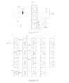
[0016] Em uma forma de realização vantajosa está previsto que as unidades divisoras de feixe sejam projetadas com uma superfície de reflexão para a luz irradiada pela unidade de tela por uma transversal, ou seja, girar ou oscilar pelo menos substancialmente perpendicularmente ao eixo de rotação que corre na primeira direção. O eixo de rotação pode, por exemplo, correr paralelo à direção y. Consequentemente, a unidade divisora de feixe e/ou superfície de reflexão tem preferivelmente uma direção de extensão principal que corre paralela ao eixo de rotação.[0016] In an advantageous embodiment, provision is made for the beam-splitter units to be designed with a reflection surface for the light radiated by the screen unit by a transversal, i.e. rotate or oscillate at least substantially perpendicularly to the axis of rotation running in the first direction. The axis of rotation can, for example, run parallel to the y direction. Accordingly, the beam-splitter unit and/or reflection surface preferably has a principal extension direction that runs parallel to the axis of rotation.
[0017] Neste caso, as unidades divisoras de feixe podem ser projetadas, por exemplo, como unidades de varredura oscilantes com espelhos oscilantes ressonantes como superficies de reflexão parcialmente transparentes. Cada espelho pode ser equipado com seu próprio elemento de mola. A superfície de reflexão pertencente a uma respectiva unidade divisora de feixe oscila então em torno do eixo de rotação quando usada de acordo com as especificações, de modo que a segunda faixa direcional seja especificada pelas faixas direcionais entre as respectivas posições finais das superficies de reflexão das unidades divisoras de feixe. Neste caso, a velocidade de rotação das superficies de reflexão é zero nas posições finais. A transparência parcial pode, por exemplo, ser tecnicamente implementada desta forma, em que é usado um material transparente para as unidades divisoras de feixe, material esse que pode ser fornecido com um revestimento, por exemplo, vidro com um revestimento dielétrico. Alternativamente, uma abordagem de bolinhas também pode ser escolhida, na qual os orifícios são introduzidos em uma superfície refletora em uma razão de divisão predeterminada. Isto tem a vantagem adicional de que o amortecimento do ar durante oscilação é reduzido. No entanto, é possível um grande número de espelhos oscilantes conhecidos, espelhos parcialmente transparentes e respectivos conceitos de acionamento, como é conhecido no estado da técnica. Por exemplo, as unidades divisoras de feixe também podem ser projetadas como unidades de varredura rotativas cujas respectivas superficies de reflexão giram em torno do eixo de rotação. Neste caso, a segunda faixa direcional é então especificada pelas larguras das respectivas superficies de reflexão em um plano perpendicular ao eixo de rotação. A luz difusa nas bordas das superficies refletoras pode ser evitada escurecendo as bordas e/ou esmerilhando as bordas de tal forma que nenhuma borda seja visível devido ã perspectiva. As desvantagens do projeto das unidades divisoras de feixe como unidades de varredura rotativas em comparação com o projeto como unidades de varredura oscilantes são o momento angular resultante e o mecanismo que pode produzir ruido. O controle simplificado e a velocidade angular constante são vantajosos.[0017] In this case, the beam-splitter units can be designed, for example, as oscillating scan units with resonant oscillating mirrors as partially transparent reflection surfaces. Each mirror can be equipped with its own spring element. The reflection surface belonging to a respective beam-splitter unit then oscillates about the axis of rotation when used according to specifications, so that the second directional range is specified by the directional ranges between the respective end positions of the reflection surfaces of the beam splitter units. In this case, the rotation speed of the reflection surfaces is zero at the final positions. Partial transparency can, for example, be technically implemented in this way, where a transparent material is used for the beamsplitter units, which material can be provided with a coating, for example glass with a dielectric coating. Alternatively, a polka dot approach can also be chosen, in which holes are introduced into a reflective surface at a predetermined split ratio. This has the added advantage that damping of the air during swing is reduced. However, a large number of known oscillating mirrors, partially transparent mirrors and related drive concepts are possible, as is known in the prior art. For example, beam splitter units can also be designed as rotary scan units whose respective reflection surfaces rotate around the axis of rotation. In this case, the second directional range is then specified by the widths of the respective reflection surfaces in a plane perpendicular to the axis of rotation. Scattered light at the edges of reflective surfaces can be avoided by darkening the edges and/or grinding the edges such that no edges are visible due to perspective. The disadvantages of designing beamsplitter units as rotating scan units compared to designing as oscillating scan units are the resulting angular momentum and mechanism that can produce noise. Simplified control and constant angular velocity are advantageous.
[0018] Em uma outra forma de realização vantajosa está previsto que as unidades divisoras de feixe sejam projetadas para estarem em uma relação de fase predeterminada (fixa) entre si durante o funcionamento com a frequência de varredura uniforme. Neste caso, em particular para dois ou mais grupos de unidades divisoras de feixe, que preferivelmente consistem em unidades divisoras de feixe que não são imediatamente adjacentes, são especificadas fases que se desviam umas das outras. Um deslocamento de fase para as unidades divisoras de feixe é assim fixado entre os respectivos grupos de modo que as unidades divisoras de feixe de cada grupo tenham superficies de reflexão que correm permanente ou constantemente paralelas umas às outras devido a fases idênticas, mas as superficies de reflexão das unidades divisoras de feixes de grupos diferentes não correm paralelas umas às outras permanente ou constantemente. As unidades divisoras de feixe de um grupo estão, portanto, na mesma fase durante a operação. Esse grupo também pode incluir todas as unidades divisoras de feixe, de modo que todas as superficies de reflexão fiquem paralelas umas às outras permanentemente. Se, por exemplo, quando divididas em dois grupos, as unidades divisoras de feixe são controladas de tal forma que todas as unidades divisoras de feixe oscilam na mesma frequência de varredura, mas as unidades divisoras de feixe de um grupo têm uma mudança de fase em relação aos elementos divisores de feixe dos outros grupos.[0018] In another advantageous embodiment, it is envisaged that the beam-splitter units are designed to be in a predetermined (fixed) phase relationship with each other during operation at uniform sweep frequency. In this case, in particular for two or more groups of beamsplitter units, which preferably consist of beamsplitter units that are not immediately adjacent, phases are specified that deviate from each other. A phase shift for the beam-splitter units is thus fixed between the respective groups so that the beam-splitter units of each group have reflection surfaces that run permanently or constantly parallel to each other due to identical phases, but the reflection surfaces reflection from beamsplitter units of different groups do not run parallel to each other permanently or constantly. The beamsplitter units in a group are therefore in the same phase during operation. This group can also include all beamsplitter units, so that all reflecting surfaces are permanently parallel to each other. If, for example, when divided into two groups, the beamsplitter units are controlled in such a way that all beamsplitter units oscillate at the same scanning frequency, but the beamsplitter units in one group have a phase shift in relative to the beam-splitting elements of the other groups.
[0019] Isso tem o efeito de que a unidade de tela linha por linha nunca pode ser observada simultaneamente pelo usuário através de duas unidades divisoras de feixe adjacentes. A imagem virtual, ou seja, as informações de imagem geradas por computador, podem ser alteradas por meio de software de forma que uma imagem virtual livre de artefatos seja criada. Surgem os artefatos assim evitáveis, se a unidade de tela linha por linha não for fotografada ao infinito, por exemplo, com o elemento de lente acima mencionado entre a unidade de tela e as unidades divisoras de feixe. Neste caso, um deslocamento vertical das unidades divisoras de feixe tem o efeito de que a imagem virtual seja exibida com um deslocamento vertical. Correspondentemente, se todas as unidades divisoras de feixe forem operadas com a mesma fase, áreas parciais da imagem vertical irão se sobrepor. Como resultado, surgem imagens duplas, os artefatos mencionados e evitáveis com o agrupamento das unidades divisoras de feixe. A divisão em dois (ou mais) grupos de unidades divisoras de feixe em combinação com um deslocamento vertical dependente do ângulo nas informações 13/41 de imagem geradas por computador, da correção de artefato, evita assim a formação de imagens duplas. 0 artefato de uma ampliação também pode ser corrigido de forma análoga.[0019] This has the effect that the line-by-line screen unit can never be viewed simultaneously by the user through two adjacent beamsplitter units. The virtual image, that is, the computer-generated image information, can be altered through software so that an artifact-free virtual image is created. Artifacts thus avoidable arise if the screen unit is not photographed line-by-line at infinity, for example with the aforementioned lens element between the screen unit and the beam-splitter units. In this case, a vertical shift of the beamsplitter units has the effect that the virtual image is displayed with a vertical shift. Correspondingly, if all beamsplitter units are operated with the same phase, partial areas of the vertical image will overlap. As a result, double images arise, the artifacts mentioned and avoidable with the grouping of the beam splitter units. The division into two (or more) groups of beam-splitter units in combination with an angle-dependent vertical shift in the computer-generated
[0020] Em uma outra forma de realização vantajosa está previsto que as unidades divisoras de feixe estejam dispostas uma atrás da outra quando vistas em uma direção vertical, em particular na primeira direção, de modo que a luz irradiada pela unidade de tela atinja uma respectiva unidade divisora de feixe e tenha passado anteriormente (transmitida) pelas outras unidades divisoras de feixe, que estão dispostos entre a respectiva unidade divisora de feixe e a unidade de tela. Neste caso, a distância entre as unidades divisoras de feixe adjacentes, preferivelmente, aumenta de cima para baixo, ou seja, com o aumento da distância da unidade de tela.[0020] In another advantageous embodiment, provision is made for the beam-splitter units to be arranged one behind the other when viewed in a vertical direction, in particular in the first direction, so that the light radiated by the screen unit strikes a respective beam-splitter unit and has previously passed (transmitted) the other beam-splitter units, which are disposed between the respective beam-splitter unit and the screen unit. In this case, the distance between adjacent beamsplitter units preferably increases from top to bottom, i.e. with increasing distance from the screen unit.
[0021] Isto não só é vantajoso para o fator de forma do dispositivo de exibição para óculos, mas também pode ser feita de maneira simples a escolha da transparência ou refletância das unidades divisoras de feixe semitransparentes, que leva a uma intensidade homogênea da imagem virtual na direção vertical. Neste caso, uma intensidade Iar da imagem virtual é composta pelas intensidades dos espelhos parciais individuais I1 a Ii, que têm uma refletância R e, portanto, uma transmissão de (1-R). Com uma intensidade Id constante da unidade de tela, resultam assim diferentes superficies laterais de reflectância parcial para o número exemplificativo de unidades divisoras de feixe i=6 com uma intensidade constante da imagem virtual Iar = I1 = I2 = . . = I6 = const, e I1 = R1 * Id, I2 = (1-R1) * R2 * Id, ... I6 = (1-R1) * (1-R2) * (1-R3) * (1-R4) * (1-R5) * R6 * Id, e portanto por exemplo R6 = 30%, R5 = 23%, R4 = 19%, R3 = 16%, R2 = 14% e R1 = 12%. Neste caso, a mesma quantidade de luz por divisor de feixe parcialmente transparente é refletida para o olho do usuário. No entanto, há uma redução na transmissão para verificação e, portanto, percepção do ambiente real pelo usuário, o que alquns usuários podem achar desconfortável em determinadas circunstâncias. Alternativamente, você também pode trabalhar com uma reflectância constante de R=20%, por exemplo, e ajustar adicionalmente a intensidade do visor em função da luz vertical, ou seja, uma posição angular das unidades divisoras de feixe, pode ser variada de tal forma que a imagem virtual seja percebida com uma intensidade constante em todo o campo de visão vertical.[0021] This is not only advantageous for the form factor of the display device for glasses, but also the choice of transparency or reflectance of the semitransparent beamsplitter units can be made in a simple way, which leads to a homogeneous intensity of the virtual image in the vertical direction. In this case, an intensity Iar of the virtual image is composed of the intensities of the individual partial mirrors I1 to Ii, which have a reflectance R and therefore a transmission of (1-R). With a constant intensity Id of the screen unit, different lateral surfaces of partial reflectance thus result for the exemplary number of beamsplitter units i=6 with a constant intensity of the virtual image Iar = I1 = I2 = . . = I6 = const, and I1 = R1 * Id, I2 = (1-R1) * R2 * Id, ... I6 = (1-R1) * (1-R2) * (1-R3) * (1- R4) * (1-R5) * R6 * Id, and therefore for example R6 = 30%, R5 = 23%, R4 = 19%, R3 = 16%, R2 = 14% and R1 = 12%. In this case, the same amount of light per partially transparent beamsplitter is reflected to the user's eye. However, there is a reduction in the transmission for verification and therefore the user's perception of the real environment, which some users may find uncomfortable in certain circumstances. Alternatively, you can also work with a constant reflectance of R=20%, for example, and additionally adjust the intensity of the display as a function of vertical light, i.e. an angular position of the beamsplitter units, can be varied in such a way that the virtual image is perceived with a constant intensity throughout the vertical field of vision.
[0022] Em uma outra forma de realização vantajosa está previsto que a primeira direção, quando o dispositivo de exibição para óculos é usado de acordo com as especificações, seja a direção vertical e a unidade de tela linha por linha esteja disposta na direção vertical acima das unidades divisoras de feixe. Isso realiza particularmente bem as vantagens descritas acima de fator de forma, peso e a maior abertura possível do campo de visão para a imagem virtual.[0022] In another advantageous embodiment it is provided that the first direction, when the display device for glasses is used in accordance with the specifications, is the vertical direction and the line-by-line screen unit is arranged in the vertical direction above beam splitter units. This realizes particularly well the advantages described above of form factor, weight and the widest possible opening of the field of view for the virtual image.
[0023] Em uma outra forma de realização vantajosa, está previsto que o comprimento como a direção de extensão principal da unidade de tela linha por linha seja de pelo menos uma ordem de grandeza, ou seja, é maior por um fator de 10, em particular por pelo menos 1,5 ordens de grandeza, ou seja, por um fator de 50, do que uma largura da unidade de tela linha por linha que corre transversalmente ao comprimento. Em particular, a largura e o comprimento da unidade de tela aqui correm transversalmente à primeira direção. Este projeto também tem a vantagem de que as vantagens descritas em relação ao fator de forma, distribuição de peso e campo de visão aberto para a imagem virtual podem ser alcançadas de uma maneira particularmente conveniente.[0023] In another advantageous embodiment, it is provided that the length as the main extension direction of the screen unit line by line is at least one order of magnitude, i.e. it is greater by a factor of 10, in particular by at least 1.5 orders of magnitude, i.e. by a factor of 50, than a line-by-line screen unit width running across the length. In particular, the width and length of the screen unit here run transversely to the first direction. This design also has the advantage that the advantages described regarding form factor, weight distribution and open field of view for the virtual image can be achieved in a particularly convenient way.
[0024] Em outra forma de realização vantajosa, está previsto que a unidade de tela linha por linha apresente uma linha de pixel, em particular exatamente uma linha de pixel, de pontos de imagem (pixels) , que são cada um formado por diferentes subpontos de imagem de cor dispostos alternadamente ao longo da linha. Os subpontos de imagem de cor (subpixels) podem ser ou incluir subpontos de imagem vermelhos, verdes ou azuis, por exemplo. Por exemplo, os subpontos de imagem de cor estão dispostos em um esquema R-G-B-R-G-B. Uma unidade de peneira linear particularmente estreita pode assim ser implementada. A unidade de tela também pode ter várias linhas de pixels.[0024] In another advantageous embodiment, it is provided that the display unit line by line displays a pixel line, in particular exactly one pixel line, of image points (pixels), which are each formed by different sub-points of color image arranged alternately along the line. Color image subpoints (subpixels) can be or include red, green, or blue image subpoints, for example. For example, the color image subpoints are arranged in an R-G-B-R-G-B scheme. A particularly narrow linear sieve unit can thus be implemented. The screen unit can also have multiple rows of pixels.
[0025] Em outra forma de realização vantajosa, pode estar previsto que a unidade de tela linha por linha apresente uma pluralidade de linhas de subpixels (em particular paralelas) dos respectivos subpixels de cores. Uma cor especifica, por exemplo, vermelho, verde ou azul, é atribuída a cada uma das linhas de subpixels. Os pontos de imagem de uma linha de subpixel, portanto, têm uma cor (única), por exemplo, dispostos em um esquema R-R-R-... para uma linha de subpixels vermelha.[0025] In another advantageous embodiment, provision can be made for the line-by-line screen unit to display a plurality of (in particular parallel) subpixel lines of the respective color subpixels. A specific color, for example red, green or blue, is assigned to each of the subpixel rows. The image points of a subpixel line therefore have a (unique) color, for example arranged in an R-R-R-... scheme for a red subpixel line.
[0026] Em particular, a unidade de tela linha por linha pode ter exatamente uma dessas linhas de subpixels com subpontos de imagem de uma cor ou de pelo menos uma dessas linhas de subpixels mais ou menos do que as outras linhas de subpixels. Assim, as respectivas bandas de subpixels de cor podem ser organizadas como linhas de subpixels monocromáticas ao longo da direção de extensão principal da unidade de tela. Com diferentes números de linhas de subpixels para as respectivas cores específicas, as diferenças tecnológicas na luminosidade dos respectivos subpixels de cor das linhas de subpixels podem ser compensadas, por exemplo, para que, por exemplo, subpixels azuis menos eficientes da linha de subpixels azul possam assim ser compensado, de modo que haja outra linha de subpixels azul na unidade de tela linha por linha. No geral, maiores intensidades da luz irradiada pela unidade de tela linha por linha podem ser realizadas com uma pluralidade de linhas de pixels ou subpixels.[0026] In particular, the line-by-line display unit can have exactly one such subpixel lines having image subdots of one color or at least one such subpixel line more or less than the other subpixel lines. Thus, the respective bands of color subpixels can be arranged as rows of monochromatic subpixels along the main span direction of the screen unit. With different numbers of subpixel lines for the respective specific colors, technological differences in the brightness of the respective color subpixels of the subpixel lines can be compensated for, for example, so that, for example, less efficient blue subpixels of the blue subpixel line can be thus be compensated, so that there is another line of blue subpixels on the screen unit line by line. In general, greater intensities of light radiated by the line-by-line screen unit can be realized with a plurality of rows of pixels or subpixels.
[0027] Várias linhas de pixels deslocadas localmente ou linhas de subpixels são escaneadas pelas unidades divisoras de feixe com um deslocamento de tempo que, no entanto, é muito pequeno para um usuário humano perceber. Se o deslocamento de tempo correspondente ao deslocamento local das diferentes linhas determinadas pela frequência de varredura for levado em consideração em um controle de deslocamento de tempo das linhas da unidade de tela, é possível exibir informações de cor para cada pixel resultante na imagem virtual como uma sobreposição das informações de cor das diferentes linhas.[0027] Several locally shifted rows of pixels or rows of subpixels are scanned by the beam splitter units with a time offset which, however, is too small for a human user to perceive. If the time shift corresponding to the local shift of the different lines determined by the scanning frequency is taken into account in a screen unit line time shift control, it is possible to display color information for each resulting pixel in the virtual image as a overlapping the color information of the different lines.
[0028] Em outra forma de realização vantajosa, está previsto que a pelo menos uma linha ou as linhas de subpixels (de um tipo) da unidade de tela linha por linha sejam implementadas na forma de respectivas instâncias várias vezes, em particular 8 vezes. Cada instância da linha de pixels ou linha de subpixels é projetada para operar com um brilho máximo que é especificado de forma diferente especificamente para cada instância. Assim, quando usado de acordo com as especificações, o dispositivo de exibição para óculos de cada pixel ou subpixel de uma instância só pode ser alternado entre dois modos de operação, a saber, um modo de operação desconectado "Desligado" e um modo de operação conectado "Ligado" com o brilho máximo especificado. Neste caso, o brilho máximo pode ser fixo, ou seja, imutável, ou variável em um esquema, por exemplo, predeterminado dinamicamente em um chamado Bit-PlaneSchema. O brilho de todos os pixels de uma instância (linha) pode assim ser comutado globalmente, por exemplo, por meio de uma corrente, de modo que o controle de brilho não precise ser controlado por meio da regulação da largura de pulso, o que seria uma alternativa. Assim, apenas um modo ligado ou desligado deve ser implementado por pixels e o brilho pode ser definido globalmente para toda a respectiva linha de instanciação. O brilho de um pixel virtual corresponde então ao brilho total dos pixels atribuídos ao pixel virtual nas diferentes instâncias. Isso simplifica consideravelmente o controle nas altas frequências de comutação que ocorrem de qualquer maneira na unidade de tela na abordagem descrita aqui. Uma vantagem adicional é que, se forem usados LEDs na unidade de tela, eles só são acionados na potência máxima por um curto período de tempo, de modo que uma intensidade máxima mais alta pode ser alcançada por um curto período de tempo. Isso pode ser implementado com o esquema de brilho máximo especificado com flexibilidade descrito, por exemplo, implementando sucessivamente uma sequência de brilho com 1, 128, 2, 64, 4, 32, 8, 16 como os respectivos valores máximos de brilho para as diferentes instâncias. Cada instância tem então um brilho máximo individualmente predeterminado pelo esquema para cada processo de varredura, cujo brilho máximo é predeterminado no próximo processo de varredura pelo próximo valor de brilho máximo no esquema de plano de bits.[0028] In another advantageous embodiment, provision is made for the at least one line or lines of subpixels (of a type) of the screen unit line by line to be implemented in the form of respective instances several times, in particular 8 times. Each instance of the row of pixels or row of subpixels is designed to operate at a maximum brightness that is specified differently specifically for each instance. Thus, when used in accordance with specifications, the eyeglass display device for each pixel or subpixel of an instance can only be switched between two modes of operation, namely, a disconnected "Off" mode of operation and an "Off" mode of operation. connected "On" at the specified maximum brightness. In this case, the maximum brightness can be fixed, ie immutable, or variable in a scheme, for example dynamically predetermined in a so-called Bit-PlaneSchema. The brightness of all pixels of an instance (line) can thus be switched globally, for example by means of a current, so that the brightness control does not need to be controlled via pulse width regulation, which would be An alternative. Thus, only one mode on or off must be implemented per pixel and brightness can be set globally for all respective instantiation line. The brightness of a virtual pixel then corresponds to the total brightness of the pixels assigned to the virtual pixel in the different instances. This considerably simplifies control at the high switching frequencies that occur in the screen unit anyway in the approach described here. An added advantage is that if LEDs are used in the display unit, they are only driven at full power for a short period of time, so that a higher maximum intensity can be achieved for a short period of time. This can be implemented with the flexibly specified maximum brightness scheme described, for example by successively implementing a brightness sequence with 1, 128, 2, 64, 4, 32, 8, 16 as the respective maximum brightness values for the different instances. Each instance then has an individually predetermined maximum brightness by the scheme for each scan process, which maximum brightness is predetermined in the next scan process by the next maximum brightness value in the bitplane scheme.
[0029] Em uma outra forma de realização vantajosa está previsto que uma pluralidade de unidades de tela linha por linha que correm pelo menos substancialmente paralelas na sua respectiva direção de extensão principal sejam fixadas ã unidade de armação, que estão cada um dispostos a uma distância diferente na direção vertical das unidades divisoras de feixe e/ou o elemento de lente disposto entre as unidades divisoras de feixe e a unidade de tela, que é introduzida mais abaixo. As unidades de tela linha por linha podem ser posicionadas por um deslocamento respectivo nas direções x e z sem ocorrer cobertura mútua. Isso tem a vantagem de que o chamado problema Vergence-Accommodation dos óculos AR pode ser eliminado. O problema de Vergence-Accommodation resulta do fato de que os óculos AR são projetados como óculos 3D e podem exibir objetos virtuais posicionados a qualquer distância. No entanto, a unidade de tela sempre tem uma posição focal a uma distância definida.[0029] In another advantageous embodiment it is provided that a plurality of line-by-line screen units running at least substantially parallel in their respective main extension direction are attached to the frame unit, which are each arranged at a distance different in the vertical direction of the beam-splitter units and/or the lens element disposed between the beam-splitter units and the screen unit, which is inserted lower down. The row-by-row screen units can be positioned by a respective offset in the x and z directions without mutual coverage occurring. This has the advantage that the so-called Vergence-Accommodation problem of AR glasses can be eliminated. The Vergence-Accommodation problem results from the fact that AR glasses are designed like 3D glasses and can display virtual objects positioned at any distance. However, the screen unit always has a focal position at a defined distance.
[0030] Como resultado, existe apenas exatamente uma distância na qual os objetos virtuais podem ser exibidos, na qual o olho também está focado nesta distância natural. Especialmente com óculos AR, que também permitem uma visão sem perturbações do ambiente natural, os usuários percebem quando objetos reais e virtuais estão posicionados ã mesma distância em relação às suas informações 3D, mas precisam ser focados em uma distância diferente em torno do objeto virtual para ser capaz de ver um objeto nitidamente a esta distância. Com o uso de duas ou mais unidades de tela linha por linha correndo uma ao lado da outra, uma exibição diferente pode ser usada dependendo da distância do objeto virtual. Artefatos podem ocorrer se várias unidades de tela linha por linha forem usadas em distâncias diferentes, que, no entanto, são resolvidos especificando dois ou mais grupos de unidades divisoras de feixe que, como descrito acima, estão em uma relação de fase fixa predeterminada respectiva entre si. Devido à profundidade de campo limitada do olho humano, apenas algumas unidades de tela são suficientes para eliminar o problema de acomodação de vergência.[0030] As a result, there is only exactly one distance at which virtual objects can be displayed, at which the eye is also focused at this natural distance. Especially with AR glasses, which also allow an undisturbed view of the natural environment, users perceive when real and virtual objects are positioned at the same distance in relation to their 3D information, but need to be focused at a different distance around the virtual object to be able to see an object clearly at this distance. With the use of two or more line-by-line screen units running next to each other, a different display can be used depending on the distance from the virtual object. Artifacts can occur if multiple line-by-line screen units are used at different distances, which, however, are resolved by specifying two or more groups of beamsplitter units which, as described above, are in a respective predetermined fixed phase relationship between each other. yes. Due to the limited depth of field of the human eye, only a few screen units are enough to eliminate the vergence accommodation problem.
[0031] Em uma outra forma de realização vantajosa está previsto que entre as unidades divisoras de feixe e uma posição de olho, que é ocupada por um olho do usuário quando o dispositivo de exibição para óculos é usado de acordo com as especificações, esteja disposto um elemento de lente, em particular com ou composto por uma lente de dispersão e/ou entre as unidades divisoras de feixe e um ambiente, que pode ser visto pelo usuário através das unidades divisoras de feixe quando o dispositivo de exibição de óculos é usado de acordo com as especificações, esteja disposto um elemento de lente, em particular com ou composto por uma lente de focagem. Uma lente de dispersão pode, portanto, ser disposta no interior do dispositivo de exibição para óculos e uma lente de focagem pode ser disposta na parte externa do dispositivo de exibição para óculos. O elemento da lente no lado interno, ou seja, entre as unidades divisoras de feixe e a posição do olho, pode garantir que a imagem virtual seja aproximada do usuário. A lente de focagem instalada no lado parte externo pode compensar esse efeito para objetos reais com uma distância focal inversa correspondente, de modo que a visão através do divisor de feixe para o ambiente natural não seja distorcida pelos elementos da lente fixados no lado interno. O elemento de lente fixado no lado interno permite, assim, percursos ópticos dentro dos óculos AR que são fotografados até o infinito e, portanto, não levam a nenhum artefato quando o percurso do feixe é visto através de dois divisores de feixe adjacentes ao mesmo tempo, enquanto todos os divisores de feixe oscilam em paralelo e ao mesmo tempo a imagem virtual é percebida a uma distância finita devido ao elemento da lente. Alternativamente, a varredura com deslocamento de fase pelas unidades divisoras de feixe também é possível, ou seja, ao especificar dois ou mais grupos de unidades divisoras de feixe de unidades divisoras de feixe não vizinhas com fases diferentes que são especificadas de forma fixa para esses grupos conforme descrito acima, distâncias diferentes também podem ser especificadas para objetos virtuais sem os elementos de lente descritos.[0031] In another advantageous embodiment it is provided that between the beam-splitter units and an eye position, which is occupied by a user's eye when the display device for eyeglasses is used in accordance with the specifications, is arranged a lens element, in particular with or composed of a scattering lens and/or between the beam-splitter units and an environment, which can be seen by the user through the beam-splitter units when the eyewear display device is used in such a way according to the specifications, a lens element, in particular with or consisting of a focusing lens, is arranged. A scattering lens may therefore be disposed on the inside of the spectacle display and a focusing lens may be disposed on the outside of the spectacle display. The lens element on the inner side, that is, between the beam splitter units and the eye position, can ensure that the virtual image is close to the user. The focusing lens installed on the outer side can compensate for this effect for real objects with a corresponding inverse focal length, so that the view through the beam splitter to the natural environment is not distorted by the lens elements fixed on the inner side. The lens element fixed on the inner side thus allows for optical paths inside the AR glasses that are photographed to infinity and therefore do not lead to any artifacts when the beam path is viewed through two adjacent beam splitters at the same time. , while all beam splitters oscillate in parallel and at the same time the virtual image is perceived at a finite distance due to the lens element. Alternatively, phase-shifted scanning across the beamsplitter units is also possible, i.e. by specifying two or more groups of beamsplitter units from non-neighboring beamsplitter units with different phases that are fixedly specified for these groups. as described above, different distances can also be specified for virtual objects without the described lens elements.
[0032] Em uma outra forma de realização vantajosa, é previsto que um outro elemento de lente, em particular com ou feito de uma lente de focagem, seja disposto entre as unidades divisoras de feixe e a unidade de tela. Em particular, o elemento de lente tem duas superficies de limite paralelas ao plano que se estendem ao longo da primeira direção, preferivelmente ao longo da direção y e z. O outro elemento de lente é, portanto, opticamente ativo em relação ã luz irradiada pela unidade de tela, mas opticamente neutro em relação ã luz proveniente ou para o ambiente de acordo com a segunda faixa direcional, de modo que o outro elemento de lente seja transparente para uma pessoa em frente ao usuário, como conhecido pelas vidraças, sem distorção. Isso significa que as expressões faciais humanas por trás da ótica são mais fáceis de reconhecer, o que é particularmente vantajoso para as telecomunicações, como já descrito.[0032] In another advantageous embodiment, provision is made for another lens element, in particular with or made up of a focusing lens, to be arranged between the beam-splitter units and the screen unit. In particular, the lens element has two plane-parallel boundary surfaces that extend along the first direction, preferably along the y and z direction. The other lens element is therefore optically active with respect to light radiated by the screen unit, but optically neutral with respect to incoming light or the environment in accordance with the second directional range, so that the other lens element is transparent to a person in front of the user, as known from the glazing, without distortion. This means that human facial expressions behind the optics are easier to recognize, which is particularly advantageous for telecommunications, as already described.
[0033] Em uma outra forma de realização vantajosa, é proporcionada uma unidade de diafragma fixada à unidade de armação. A unidade de diafragma tem um diafragma que corre transversalmente à primeira direção e/ou um diafragma paralelo a um plano estendido pelas unidades divisoras de feixe, o plano y-z, para proteger a luz da unidade de tela defletida pelas unidades divisoras de feixe contra a luz incidente de direções adjacentes à primeira direção. Ou seja, essa luz, como luz dispersa, tem o potencial de deteriorar a imagem virtual. Dependendo da orientação do olho do usuário, em frente, acima ou abaixo, as luzes de diferentes direções adjacentes ã primeira direção são particularmente prejudiciais. Estas luzes podem ser protegidas de forma particularmente eficaz com as duas telas descritas.[0033] In another advantageous embodiment, a diaphragm unit fixed to the frame unit is provided. The diaphragm unit has a diaphragm running transversely to the first direction and/or a diaphragm parallel to a plane extended by the beam splitter units, the y-z plane, to shield light from the screen unit deflected by the beam splitter units from light. incident from directions adjacent to the first direction. That is, this light, like scattered light, has the potential to deteriorate the virtual image. Depending on the user's eye orientation, forward, above or below, lights from different directions adjacent to the first direction are particularly harmful. These lights can be protected particularly effectively with the two screens described.
[0034] Os recursos e combinações de recursos mencionados acima na descrição, inclusive na parte introdutória, e os recursos e combinações de recursos mencionados abaixo na descrição das Figuras e/ou mostrados isoladamente nas Figuras não estão apenas na combinação especificada em cada caso, mas também em outras combinações podem ser usadas sem sair do escopo da invenção. A invenção também deve, portanto, ser considerada para incluir e divulgar formas de realização que não são explicitamente mostrados e explicados nas Figuras, mas resultam das versões explicadas e podem ser gerados por combinações separadas de características. Versões e combinações de características também devem ser consideradas como divulgadas que, portanto, não possuem todas as características de uma reivindicação independente originalmente formulada. Além disso, as formas de realização e combinações de características, em particular através das formas de realização apresentadas acima, devem ser consideradas como divulgadas que vão além ou se desviam das combinações de características apresentadas nas referências posteriores das reivindicações.[0034] The features and combinations of features mentioned above in the description, including in the introductory part, and the features and combinations of features mentioned below in the description of the Figures and/or shown separately in the Figures are not only in the combination specified in each case, but also in other combinations they can be used without departing from the scope of the invention. The invention must therefore also be considered to include and disclose embodiments that are not explicitly shown and explained in the Figures, but result from the explained versions and can be generated by separate combinations of features. Versions and combinations of features should also be considered as disclosed which therefore do not have all the features of an originally formulated independent claim. Furthermore, the embodiments and combinations of features, in particular through the embodiments presented above, are to be considered as disclosed that go beyond or deviate from the combinations of features presented in later references of the claims.
[0035] O objeto de acordo com a invenção deve ser explicado em mais detalhes com referência aos desenhos esquemáticos mostrados nas Figuras seguintes, sem desejar restringi-lo às formas de realização específicas mostradas aqui. Em que:[0035] The object according to the invention should be explained in more detail with reference to the schematic drawings shown in the following Figures, without wishing to restrict it to the specific embodiments shown here. On what:
[0036] A Figura 1 mostra uma forma de realização exemplificativa de um dispositivo de exibição para óculos para exibir uma imagem virtual no campo de visão de um usuário em uma vista em perspectiva frontal;[0036] Figure 1 shows an exemplary embodiment of a display device for eyewear for displaying a virtual image in a user's field of vision in a front perspective view;
[0037] A Figura 2 mostra a forma de realização exemplificativa da Figura 1 em uma vista em corte lateral esquemática;[0037] Figure 2 shows the exemplary embodiment of Figure 1 in a schematic side sectional view;
[0038] A Figura 3 mostra situações exemplificativas para luz dispersa deteriorando a imagem virtual;[0038] Figure 3 shows exemplary situations for scattered light deteriorating the virtual image;
[0039] A Figura 4 mostra diferentes detalhes de uma outra forma de realização exemplificativa de um dispositivo de exibição para óculos;[0039] Figure 4 shows different details of another exemplary embodiment of a display device for glasses;
[0040] A Figura 5 mostra diferentes formas de realização exemplificativas de unidades de tela linha por linha;[0040] Figure 5 shows different exemplary embodiments of line-by-line screen units;
[0041] A Figura 6 mostra uma visão geral de outro dispositivo de exibição para óculos exemplificativo;[0041] Figure 6 shows an overview of another exemplary eyewear display device;
[0042] A Figura 7 mostra uma ilustração de uma forma de realização exemplificativa de um dispositivo de exibição para óculos com unidades de varredura rotativas.[0042] Figure 7 shows an illustration of an exemplary embodiment of a display device for eyewear with rotatable scanning units.
[0043] Nas Figuras, os elementos que são iguais e têm a mesma função são dotados dos mesmos símbolos de referência.[0043] In the Figures, elements that are the same and have the same function are provided with the same reference symbols.
[0044] A Figura 1 mostra uma forma de realização exemplificativa de um dispositivo de exibição para óculos para exibir uma imagem virtual no campo de visão de um usuário. 0 dispositivo de exibição para óculos 0 tem uma unidade de armação 17 com uma unidade de sustentação 16 e uma unidade de sustentação adicional 15. Na forma de realização mostrada, uma unidade de tela linha por linha 29 está disposta na unidade de armação 17, aqui a unidade de sustentação 15, da qual duas áreas parciais 141, 142 são atribuídas ao olho direito e esquerdo 20 (Figura 2) do usuário. A unidade de tela linha por linha 29 serve para irradiar luz ao longo de um percurso de feixe 226 (Figura 2) como informação de imagem gerada por computador em uma primeira direção, aqui a direção z negativa. O dispositivo de exibição para óculos 0 também tem várias unidades divisoras de feixe parcialmente transparentes 10 fixadas à unidade de armação 17, aqui a unidade de sustentação 16, que são projetadas para serem operadas como unidades de varredura com uma frequência de varredura definida uniformemente, para desviar a luz irradiada pela unidade de tela 29 na primeira direção, a direção z negativa, para uma segunda faixa direcional, que corresponde ao campo de visão do usuário quando o dispositivo de exibição para óculos 0 é usado de acordo com as especificações. No presente caso, a segunda faixa direcional corre essencialmente ao longo da direção x negativa.[0044] Figure 1 shows an exemplary embodiment of a display device for eyewear for displaying a virtual image in a user's field of view. The
[0045] No presente caso, um outro elemento de lente 13, aqui uma chamada óptica Pancake com duas lentes 11, 12, está disposta entre as unidades divisoras de feixe 10 e a unidade de tela 29. No plano do desenho, isto é, no plano y-z, o elemento de lente 13 no presente caso tem duas superficies de fronteira planas paralelas (consequentemente correndo ao longo da primeira direção), de modo que não haja reprodução distorcida das expressões faciais do usuário para um terceiro visualizador. As unidades divisoras de feixe 10 são dispostas uma atrás da outra na direção vertical, vistas aqui na direção z positiva, ou seja, uma acima da outra na direção z, de modo que a luz irradiada pela unidade de tela 29 incida sobre uma respectiva unidade divisora de feixe 10 e tenha passado anteriormente através daquelas outras unidades divisoras de feixe 10, que estão dispostos entre a respectiva unidade divisora de feixe 10 e a unidade de tela 29. À medida que a distância da unidade de tela 29 aumenta, a distância entre as unidades divisoras de feixe 10 também aumenta no exemplo mostrado.[0045] In the present case, another
[0046] No exemplo acima, seis unidades divisoras de feixe parcialmente transparentes 10 projetadas como unidades de varredura são mostradas para cada olho, que têm um respectivo eixo de rotação ou eixo de rotação 24 (Figura 2) ao longo do eixo y. Como as unidades divisoras de feixe 10 são projetadas, por exemplo, com uma unidade de controle correspondente, para serem operadas com uma frequência de varredura uniformemente fixa, consegue-se que as unidades de varredura individuais com superficies de reflexão parcialmente transparentes associadas oscilem de forma síncrona umas com as outras. Neste caso, síncrono significa que a fase das unidades divisoras de feixe em relação uma à outra é constante. 0 outro elemento de lente 13 fotografa a unidade de tela linha por linha 29 de tal forma que pode ser vista pelo olho do usuário 20 (Figura 2) através das unidades divisoras de feixe parcialmente transparentes 10 em uma grande parte do campo de visão humano natural. O campo de visão que pode ser usado para a imagem virtual é determinado horizontalmente pela extensão das unidades divisoras de feixe 10, a óptica 13 e a unidade de tela linha por linha 29 na direção y. Na direção vertical, o campo de visão que pode ser usado para a imagem virtual é determinado pela deflexão mecânica das unidades de varredura 10, cuja largura é transversal à sua direção de extensão principal e pelo número de unidades de varredura 10 usadas, uma vez que cada unidade de varredura individual pode cobrir apenas uma parte do campo de visão vertical.[0046] In the example above, six partially
[0047] No exemplo mostrado, o outro elemento de lente 13 é tão pronunciado que através das lentes 11, 12 a partir da direção frontal, ou seja, é possível uma visualização sem distorção na direção x negativa. Isto é possível porque as lentes 11, 12 são cortadas como tiras na direção x, ou seja, têm uma característica significativamente mais longa na direção y do que na direção x. "Significativo" pode ser entendido aqui, por exemplo, como uma diferença de pelo menos uma ordem de grandeza, por exemplo, uma extensão de 6 mm na direção x e 70 mm na direção y. No presente exemplo, a óptica Pancake para o outro elemento de lente 13 é selecionada como um exemplo e também pode ser substituída por outras ópticas.[0047] In the example shown, the
[0048] A Figura 2 mostra uma vista esquemática em corte lateral do dispositivo de exibição para óculos da Figura 1. 0 olho 20 do usuário olha através de uma pupila 21 para o arranjo das unidades divisoras de feixe 10 projetadas como unidades de varredura e, portanto para varredura, cada uma girando em torno do seu eixo de rotação 24. As unidades divisoras de feixe 10 têm uma faixa angular mecânica 243 entre duas posições finais 241, 242. Esta faixa angular mecânica 243 requer uma faixa angular óptica 231, 232 que, como uma segunda faixa direcional, corresponde ao campo de visão do usuário utilizável através da imagem virtual. Em principio, a faixa angular mecânica 243 também pode ser selecionada para ser maior aqui, caso em que a unidade de tela linha por linha 29 é usada apenas se um percurso de feixe passar dentro dos limites 221, 222. No presente caso, as delimitações 221, 222 correspondem ao campo de visão humano natural do usuário. Esta área de visualização é disposta simetricamente em torno de uma direção principal central 225, que deve ser preferivelmente também o centro da área de varredura mecânica ou área angular 243. Idealmente, o alinhamento das unidades divisoras de feixe parcialmente transparentes 10 na posição de repouso é escolhido de modo que a luz paralela seja desviada ao longo do percurso de feixe 226 para fora da unidade de tela 29 na direção 225. As unidades divisoras de feixe 10 são síncronas, ou seja, todos operados com a mesma frequência de varredura. Conforme explicado mais abaixo na Figura 4, uma forma com uma mudança de fase relativa entre unidades divisoras de feixe individuais 10 pode ser selecionada, ou, como mostrado na presente Figura, sem deslocamento de fase entre diferentes unidades divisoras de feixe 10. Neste último caso, as superficies de reflexão de todas as unidades divisoras de feixe parcialmente transparentes 10 estão dispostas em paralelo.[0048] Figure 2 shows a schematic view in side section of the eyeglass display device of Figure 1. The user's
[0049] Neste exemplo, as unidades divisoras de feixe 10 são posicionadas uma acima da outra na direção z a uma distância vertical 251, 252, que difere dependendo da altura na direção z, dependendo da posição vertical no campo de visão. Por exemplo, as unidades divisoras de feixe 10 podem ser posicionadas tão próximas umas das outras que um percurso de feixe de visualização 224 a partir do centro de rotação do olho 20 ou globo ocular intercepta a borda inferior 261 de uma unidade divisora de feixe superior 10 e ao mesmo tempo cruza a borda superior 262 de uma unidade divisora de feixe inferior 10. No entanto, distâncias mais estreitas e também distâncias maiores também são concebíveis. No caso de arranjos mais próximos, um percurso de feixe de visualização pode ser desviado por duas unidades divisoras de feixe 10 ao mesmo tempo. Para que isso não leve a artefatos de imagem, o elemento de lente adicional 13 deve ser projetado no presente caso de tal forma que os raios de luz sejam visualizados até o infinito, ou seja, um feixe de luz paralelo a ser desviado esteja presente. A imagem virtual pode então ser movida de volta para uma distância virtual finita por um elemento de lente côncava 283 entre o usuário e as unidades divisoras de feixe 10. Para que a visão através do divisor de feixe 10 para os objetos reais no ambiente natural não seja distorcida pelo elemento de lente 283, isso pode ser corrigido novamente por um elemento de lente 282 com uma distância focal inversa em uma parte externa do dispositivo de exibição para óculos 0. Os elementos de lente 283 e 284 não são mais necessários se a varredura defasada for usada, como será explicado em mais detalhes na Figura 4.[0049] In this example, the
[0050] Na Figura 3, são considerados os percursos de feixe que, como luz dispersa, têm o potencial de degradar a imagem virtual.[0050] In Figure 3, beam paths are considered that, as scattered light, have the potential to degrade the virtual image.
[0051] A Figura 3a mostra uma situação com uma visão horizontal em linha reta, como resultado da qual o olho 20 focaliza um pixel da imagem virtual que é visível na direção horizontal, direção x. Uma vez que as unidades divisoras de feixe 10 varrem a unidade de tela linha por linha com uma frequência de varredura de, por exemplo, 50 Hertz, outras fontes de luz 311, 312 e 313 do ambiente natural também são sobrepostas no pixel virtual em consideração por um curto período de tempo de acordo com o percurso do feixe 30 em um ciclo de varredura. Essas fontes de luz 311, 312 e 313 do ambiente natural podem ser divididas em três faixas angulares 321, 322 e 323.[0051] Figure 3a shows a situation with a straight horizontal view, as a result of which the
[0052] As fontes de luz 313, que estão ã esquerda da vertical na faixa angular 323 na ilustração mostrada e, portanto, estão mais próximas do olho 20 do que a unidade de tela 29 vista na direção x, são de fato sobrepostas na imagem virtual, no entanto, devido à proximidade do dispositivo de exibição para óculos 0 ao usuário, o rosto é mostrado aqui. Uma vez que isso é iluminado apenas externamente, é uma área comparativamente escura que contribui apenas com uma pequena quantidade de luz difusa, conforme ilustrado pelo percurso do feixe de limite 302. Isto deve ser avaliado em relação à unidade de tela linha por linha comparativamente brilhante 29 no percurso de feixe 301. No presente caso, o percurso de feixe de limite 302 corresponde à posição final 242 da unidade divisora de feixe associada 10.[0052] The
[0053] Além disso, há uma faixa angular 322 de fontes de luz 312 que estão suficientemente distantes do dispositivo de exibição para óculos 0 na direção x, que não pode mais ser percebida como luz difusa através das unidades divisoras de feixe de varredura 10. A faixa angular 321 permanece assim entre as outras duas faixas angulares 323, 322, nas quais as fontes de luz 311, como lâmpadas externas ou um céu claro, podem ser localizadas, o que pode potencialmente fazer uma grande contribuição para a luz difusa. A fim de não ter que contar com um boné como protetor de cabeça ou semelhante, as telas 33, 34 podem ser usadas para bloquear esta faixa angular 321, na qual o percurso de feixe limite 303 correspondente à posição final 241 conduz no presente caso. Os diafragmas 33, 34 podem ser projetados tanto como um diafragma horizontal 33 (diafragma 33 com um plano de diafragma correndo horizontalmente no plano x-y) e/ou como um diafragma vertical 34 (diafragma 34 com um plano de diafragma correndo verticalmente no plano z-y), por exemplo, como uma tonalidade de lente gradiente diretamente no óculos do dispositivo de exibição para óculos 0.[0053] Furthermore, there is an
[0054] Na Figura 3b é mostrado que o problema da luz difusa é menos relevante para as direções de visualização para baixo, na direção z negativa, uma vez que a luz difusa chega a uma proporção aumentada da área do rosto do usuário e, portanto, tipicamente em comparação com o ambiente é comparativamente escuro. Além disso, fica claro aqui que é vantajoso dispor a faixa angular usada para a imagem virtual inclinada para baixo em relação ã horizontal, por exemplo, +20° para cima a partir da horizontal e -40° para baixo a partir da horizontal.[0054] In Figure 3b it is shown that the problem of stray light is less relevant for downward viewing directions, in the negative z direction, since the stray light reaches an increased proportion of the user's face area and therefore , typically compared to the environment is comparatively dark. Furthermore, it is clear here that it is advantageous to have the angular range used for the virtual image tilted downwards with respect to the horizontal, for example +20° upwards from the horizontal and -40° downwards from the horizontal.
[0055] Na Figura 3c é visualizado que a abertura 33, 34 é particularmente relevante quando o olho 20 é direcionado para cima, uma vez que os percursos do feixe 302, 303 levam ambos para a faixa angular 321. Aqui, uma abertura comparativamente pequena 33, 34 é suficiente para reduzir efetivamente a luz difusa.[0055] In Figure 3c it is seen that the
[0056] A consideração da luz difusa também mostra que é vantajoso escolher uma refletância relativamente baixa para as unidades divisoras de feixe 10 e aumentar a luminosidade da unidade de tela linha por linha 29 em vez de, inversamente, escolher uma unidade de tela de baixa luminosidade 29 em combinação com alta refletância das unidades divisoras de feixe 10. Isso resulta em um maior contraste em relação à luz difusa e, além disso, maior transparência ao olhar através de objetos reais no ambiente natural do usuário.[0056] Consideration of stray light also shows that it is advantageous to choose a relatively low reflectance for the
[0057] A Figura 4 mostra uma variante na qual as unidades divisoras de feixe 10 foram divididas em dois grupos diferentes 411, 412, que todos oscilam na mesma frequência de varredura, mas as unidades divisoras de feixe 10 de um grupo 411 têm um deslocamento de fase em relação às unidades divisoras de feixe 10 do outro grupo 412. Assim, a unidade de tela linha por linha 29 nunca é vista através de duas unidades divisoras de feixe adjacentes 10 ao mesmo tempo. A informação de imagem gerada por computador da unidade de tela linha por linha 29 pode assim ser gerada individualmente para cada unidade divisora de feixe 10. Isso resulta nas vantagens de que tolerâncias de fabricação, desvios cinemáticos e outros erros podem ser corrigidos por software. Assim, por exemplo, percursos de feixe 22 6 que não são focados ao infinito também podem ser realizados e assim, por exemplo, os elementos de lente 283, 284 acima podem ser dispensados. Isso também resulta na possibilidade de dispor várias unidades de tela linha por linha 291, 292, 293 (Figura 4b) a diferentes distâncias para resolver o chamado problema de Vergence-Accommodation.[0057] Figure 4 shows a variant in which the
[0058] A Figura 4a mostra como as unidades divisoras de feixe 10 podem ser divididas em dois grupos alternados 411, 412, ou seja, em dois grupos 411, 412, que consistem cada um em unidades divisoras de feixe não adjacentes 10 e juntas contêm todas as unidades divisoras de feixe 10. Dentro do respectivo grupo 411, 412, as unidades divisoras de feixe 10 estão em fase e, portanto, alinhadas paralelamente uma ã outra com suas superficies de reflexão parcialmente transparentes. Ambos os grupos 411, 412 também têm a mesma frequência de varredura, mas suas unidades divisoras de feixe 10 são desfasadas uma em relação ã outra. No exemplo mostrado aqui, a mudança de fase é de 90°, em que uma oscilação sinusoidal por oscilação completa abrange 360°. A Figura 4c mostra que neste exemplo é assumida uma deflexão mecânica máxima dos espelhos de ±30°.[0058] Figure 4a shows how the
[0059] Com os dois grupos 411, 412, a imagem virtual pode efetivamente ser gerada individualmente para cada unidade divisora de feixe 10, conforme explicado abaixo. Por uma questão de clareza, apenas uma única unidade divisora de feixe 10 é mostrada como uma unidade de varredura na Figura 4b. A partir da unidade de tela 29, a luz é desviada em um ângulo máximo com caminho de feixe 425 até um ângulo mínimo com percurso de feixe resultante 424. Uma vez que a pupila 21 tem apenas uma abertura comparativamente pequena, os percursos de feixe 424 e 425 das situações limítrofes já não são visíveis ao olho humano 20. Apenas percursos de feixes nos quais pelo menos um pequeno feixe de raios atinge a pupila são efetivamente visíveis, por exemplo, os feixes de raios 422 e 423. Isso resulta em uma área de varredura efetiva por unidade divisora de feixe 10, que é relevante para a formação real da imagem e que é menor do que a área de varredura tecnicamente implementada. No exemplo mostrado aqui, a faixa de varredura efetiva é de ±7° em torno de uma posição de repouso da unidade divisora de feixe 10. Este faixa angular eficaz por unidade divisora de feixe 10 pode ser projetada para um tamanho físico de pupila ou aumentada para levar em consideração o movimento do olho 20. Como o olho 20 está sempre se realinhando, o desenho pode ser feito de acordo por meio de uma pupila imaginária resultante 21 que é aumentada em relação á pupila real. Uma outra alternativa é, portanto, o uso de um sensor de rastreamento ocular 49 (rastreamento ocular). A faixa angular pode assim ser medida continuamente e as correções na unidade de exibição 29 podem ser ajustadas continuamente por software. Uma mistura é preferivelmente usada, resultando na vantagem de a pupila 21 do olho 20 não precisar ser medida com uma precisão muito alta. Além disso, um alinhamento das unidades divisoras de feixe 10 também pode ser reajustado continuamente para diferentes usuários do dispositivo de exibição para óculos 0 dessa maneira. Ao dividir as unidades divisoras de feixe 10 nos dois grupos 411, 412, pode-se garantir que os percursos de feixe de diferentes unidades divisoras de feixe 10 não se sobreponham na pupila 21, de modo que apenas a luz de uma única unidade divisora de feixe 10 seja percebida. Neste caso, no entanto, as unidades divisoras de feixe 10 podem ser dispostas a uma distância tão pequena umas das outras na direção z que uma exibição ininterrupta da imagem virtual na direção z é, no entanto, possível.[0059] With the two
[0060] A Figura 4c mostra os ciclos de oscilação dos dois grupos 411, 412 como gráficos 451 e 452 da deflexão angular mecânica S (eixo y) sobre as fases da oscilação P como (eixo x) . A área com altura 44 (direção do eixo y) e largura 43 (direção do eixo x) marca os (idealmente apenas) vezes em que a unidade de tela 29 é ligada, ou seja, a luz é irradiada. Devido ã mudança de fase, o gráfico 452 do segundo grupo 412 tem nestes momentos deflexões angulares mecânicas na área 47. Estas são tão grandes que nenhum percurso de feixe conduz da unidade de tela 29 ao olho 20 ou ã pupila 21. A mudança de fase entre os dois grupos 411 e 412, bem como a deflexão mecânica (angular) máxima é selecionada de tal forma que há um período em que nenhum percurso do feixe pode ser visto, ou seja, a faixa angular 46 e a faixa de fase 48. Este período de tempo pode ser estruturalmente reduzido a zero pelo fato de que os percursos de feixe do segundo grupo 412 se tornam visíveis no momento em que os percursos de feixe do primeiro grupo 411 não são mais visíveis, em que os percursos ópticos do segundo grupo 412 se tornam visíveis minimizando a região de fase 48.[0060] Figure 4c shows the oscillation cycles of the two
[0061] No presente caso, na Figura 4a, uma área de varredura mecânica maior, uma deflexão angular maior, é usada do que seria necessário para desviar a luz da unidade de tela 29 para a pupila 21. Isto tem a vantagem de ser alcançada uma relação aproximadamente linear entre a deflexão angular S e a fase P na área efetiva 43, 44, ou seja, uma velocidade de varredura aproximadamente constante. Assim, a unidade de tela 29 pode ser operada com brilho aproximadamente constante. Alternativamente, uma intensidade constante para a imagem virtual pode ser alcançada, em que os desvios resultantes da velocidade de varredura de variação senoidal são corrigidos, ajustando dinamicamente o brilho na unidade de exibição 29.[0061] In the present case, in Figure 4a, a larger mechanical scan area, a larger angular deflection, is used than would be necessary to divert light from the
[0062] Na Figura 5 são mostradas diferentes formas de realização exemplificativas de uma unidade de exibição linha por linha. A unidade de tela linha por linha é caracterizada em todas as Figuras parciais com a direção de extensão principal na direção y, por exemplo, organizando 4000 ou outro número de pixels 51 um ao lado do outro. Para permitir a coloração, são usados os pixels R, G, B vermelhos, verdes e azuis, preferivelmente na forma de LEDs, por exemplo, os chamados microLEDs. Neste caso, é necessário que os pixels individuais 51 sejam comutáveis muito rapidamente. Especificamente, se 2000 pixels (virtuais) devem ser gerados como uma imagem virtual com a varredura na direção de varredura 52 - por exemplo, verticalmente, ou seja, correspondendo à direção x nas Figuras, e as unidades divisoras de feixe 10 têm uma frequência de varredura de 45 Hz, ou seja, se houver duas varreduras em 90 Hz para cada pixel virtual, os LEDs devem ser alternados em 2000*90 Hz = 180 kHz. Além disso, pode ser necessário regular o brilho, normalmente com uma resolução de 8 bits, por exemplo, não acendendo o respectivo LED durante todo o tempo de varredura, mas apenas por um tempo menor. A largura de pulso mais curta para acender o LED é então correspondentemente menor por um fator de 256, o que corresponde a uma frequência de comutação de 46 MHz. Alternativamente, no entanto, a intensidade também pode ser controlada por meio de uma corrente absoluta em vez da largura de pulso da atividade do LED. Tecnologias alternativas de exibição que podem ser trocadas com rapidez suficiente também podem ser usadas. Estes incluem, por exemplo, lasers, que são projetados em uma linha da unidade de tela 29 através de um espelho MEMS.[0062] In Figure 5 different exemplary embodiments of a line-by-line display unit are shown. The line-by-line screen unit is characterized in all partial Figures with the main extension direction in the y direction, for example, arranging 4000 or another number of
[0063] A Figura 5a mostra correspondentemente uma disposição de uma linha na qual os pixels 51 das respectivas cores R, G, B estão dispostos próximos um do outro na direção y e, assim, formam a unidade de tela 29. Na Figura 5b, os pixels individuais de uma cor são dispostos na forma das respectivas linhas de subpixels 511, 512, 513 com os respectivos subpontos de imagem de cor R, G, B a uma distância um do outro que difere de zero. Isso é possível porque a direção de varredura 52 das unidades divisoras de feixe 10 varre as linhas de subpixels 511, 512, 513 de cores diferentes com um deslocamento de tempo. Se o deslocamento local na ativação for considerado de acordo com uma ativação de deslocamento temporal, surge a possibilidade de cada pixel resultante na imagem virtual exibir informações de cor como uma sobreposição.[0063] Figure 5a correspondingly shows an arrangement of a line in which
[0064] A Figura 5c expande as aplicações possíveis para que sejam exibidas várias linhas de subpixels de uma cor respectiva R, G, B. Uma cor pode ser exibida várias vezes com o objetivo de torná-la mais clara em comparação. Isso é vantajoso, por exemplo, porque as intensidades de LEDs de cores diferentes são percebidas pelo olho humano como tendo brilho espectral diferente. Na forma de realização mostrada, o número de linhas de subpixels 511, 511', 511'', 512, 513, 513' é selecionado de forma diferente com o objetivo de poder representar bem o ponto branco D65.[0064] Figure 5c expands the possible applications for displaying several rows of subpixels of a respective color R, G, B. A color can be displayed several times in order to make it lighter in comparison. This is advantageous, for example, because the intensities of different colored LEDs are perceived by the human eye as having different spectral brightness. In the shown embodiment, the number of
[0065] Outra possibilidade para controle de brilho é mostrada na Figura 5d. 0 brilho de um pixel a ser exibido é dividido nos chamados planos de bits, instâncias 18, como também é conhecido pelo controle de chips de microespelho a partir dos projetores. As informações de brilho de 8 bits também podem ser compostas por 8 imagens individuais binárias com o brilho 128, 64, 32, 16, 8, 4, 2, 1. Devido ao processo de digitalização, esses brilhos podem ser exibidos um após o outro, porque devido ã velocidade do processo de digitalização em comparação com a percepção humana, apenas a integral do brilho é reconhecida. Da mesma forma, deve ser feita apenas uma distinção entre um estado ligado e desligado por pixel, e o brilho pode ser definido globalmente para toda a linha, por exemplo, através de uma corrente adequadamente regulada. Isso simplifica significativamente o controle em altas frequências.[0065] Another possibility for brightness control is shown in Figure 5d. The brightness of a pixel to be displayed is divided into so-called bit planes, instances 18, as is also known from micromirror chip control from projectors. The 8-bit brightness information can also be composed of 8 individual binary images with the
[0066] No caso de um esquema Bit-Plane flexivelmente comutado, no qual a diferentes instâncias são atribuídos alternadamente diferentes brilhos, também existe a vantagem, que os LEDs comutados são acionados apenas brevemente com potência máxima e, portanto, uma intensidade máxima mais alta pode ser alcançada por um curto período de tempo. Para este propósito, os planos de bits são tipicamente misturados, por exemplo, implementando uma sequência de brilho como 1, 128, 2, 64, 4, 8, 16 para cada instância e, portanto, para cada linha sucessivamente. A especificação flexível da intensidade máxima para as respectivas fileiras também traz vantagens para o gerenciamento de temperatura.[0066] In the case of a flexibly switched Bit-Plane scheme, in which different instances are alternately assigned different brightnesses, there is also the advantage, that the switched LEDs are triggered only briefly at full power and therefore a higher maximum intensity can be achieved for a short period of time. For this purpose, the bit planes are typically mixed, for example by implementing a brightness sequence like 1, 128, 2, 64, 4, 8, 16 for each instance and hence for each line in succession. The flexible specification of the maximum intensity for the respective rows also brings advantages for temperature management.
[0067] A Figura 5e mostra, a titulo de exemplo, a relação entre a direção de varredura 52 e a varredura de duas linhas de subpixels 511, 512 dispostas uma ao lado da outra na direção x por meio das unidades divisoras de feixe 10.[0067] Figure 5e shows, by way of example, the relationship between the
[0068] A Figura 6 mostra agora a formação de imagem da imagem virtual em outra forma de realização exemplificativa. Neste exemplo, a luz da unidade de tela linha por linha 29 é visualizada ao infinito pelo elemento de lente 13, ou seja, paralelizada. A luz atinge assim as unidades divisoras de feixe de varredura 10 de acordo com o percurso de feixe 226 e é em cada caso parcialmente refletida e parcialmente transmitida por elas. No exemplo mostrado, a porção de luz que é sempre transmitida finalmente colide com uma superfície absorvente 61 do dispositivo de exibição para óculos 0 para evitar reflexões traseiras. A luz refletida é desviada para o olho de acordo com o percurso do feixe 621. Uma vez que cada unidade divisora de feixe de varredura 10 contribui com seu próprio feixe de raios e as unidades divisoras de feixe de varredura 10 são posicionadas aqui em uma distância divisora de feixe uma da outra que varia na direção z, os feixes individuais de raios se sobrepõem parcialmente (por exemplo, sobreposição 631) e se forma parcialmente uma lacuna não iluminada (por exemplo, lacuna 633). No entanto, apenas os raios que são dirigidos para a pupila 21, isto é, que atingem o olho 20 dentro da pupila de entrada 632, são relevantes e eficazes. Uma vez que o percurso de feixe 226 é focado ao infinito e este percurso de feixe ainda passa através da lente côncava 283 após sua reflexão nas unidades divisoras de feixe 10 no exemplo mostrado, uma imagem virtual aparece, como se tivesse surgido a uma certa distância de acordo com o caminho do feixe 622 ou 623. Para um ponto de imagem 51 que é exibido por unidade de tempo na unidade de tela linha por linha 29, o olho humano 20 vê um ponto de imagem virtual 651 como se um ponto de imagem real correspondente estivesse presente no campo de visão do usuário.[0068] Figure 6 now shows the imaging of the virtual image in another exemplary embodiment. In this example, the light from the line-by-
[0069] Uma vez que as unidades divisoras de feixe parcialmente transparentes 10 são montadas de forma móvel como unidades de varredura, uma imagem virtual bidimensional pode ser construída a partir de uma unidade de tela linha por linha 29. Se a unidade divisora de feixe 10 se move na direção 52, o percurso do feixe também muda de ângulo na direção 52. Isso tem o efeito de que a unidade de tela linha por linha 29 pode agora exibir novas informações de cor e brilho da imagem e isso pode ser percebido pelo olho humano 20 como um ponto de imagem virtual 651' em uma nova posição, ou seja, o restante da imagem pode ser construído na direção do scanner 52. Para isso é necessário que a unidade de tela em forma de linha 29 seja acionada de maneira síncrona em função da posição da unidade divisora de feixe de varredura 10. Por conseguinte, existe um sistema de sensor que pode determinar a posição das unidades divisoras de feixe 10 com precisão suficiente. Este sistema de sensores pode ser integrado nas unidades divisoras de feixe 10 ou em outra unidade de controle. A unidade de tela linha por linha 29 pode ser acionada em conformidade por uma unidade de controle 68 que está disposta externamente no dispositivo de exibição para óculos 0 ou por cabo ou por rádio ou é acoplada ao dispositivo de exibição para óculos 0.[0069] Since the partially
[0070] Se a ilusão de um objeto virtual estacionário surgir em um ambiente real, a posição do dispositivo de exibição para óculos 0 no espaço também deve ser determinada. Uma unidade de rastreamento correspondente 67 (sistema de sensor de rastreamento) pode ser usada para tal finalidade. Isso pode ter uma câmera permanentemente conectada ao dispositivo de exibição para óculos 0, por exemplo, que, em cooperação com a unidade de computação 68, permite calcular a imagem virtual de tal forma que ela aparece estaticamente ancorada no espaço.[0070] If the illusion of a stationary virtual object arises in a real environment, the position of the display device for
[0071] 0 outro elemento de lente 13 é atualmente realizado como uma seção através de uma lente. Isto resulta em duas superficies de fronteira planas paralelas 66, que permitem que outra pessoa 200 olhe através do outro elemento de lente 13 sem que ocorram distorções significativas do que está por trás delas. Assim, o outro elemento de lente 13 tem apenas uma pequena influência na aparência estética do dispositivo de exibição para óculos 0 e permite uma configuração que pelo menos se aproxima dos óculos comuns.[0071] The
[0072] A Figura 7 mostra uma ilustração de uma forma de realização exemplificativa de um dispositivo de exibição para óculos com unidades de varredura rotativa. Lá, as unidades divisoras de feixe 10 são projetadas como unidades de varredura rotativa e não como unidades de varredura oscilantes como nos exemplos acima. Os recursos não explicados podem corresponder aos recursos explicados para os outros exemplos.[0072] Figure 7 shows an illustration of an exemplary embodiment of a display device for eyewear with rotary scanning units. There, the
[0073] Na forma de realização mostrada na Figura 7a, as unidades divisoras de feixe 10 giram em torno do eixo de rotação 24 a uma velocidade angular constante e, portanto, uma frequência de varredura ou frequência de rotação uniformemente definida. Devido às condições de limite óptico em relação à disposição relativa das unidades divisoras de feixe 10 entre si e à unidade de tela 29, as unidades de varredura rotativas não podem girar na mesma direção e de forma sincronizada, uma vez que as unidades divisoras de feixe 10 se tocariam. Portanto, as unidades divisoras de feixe 10 são divididas em dois grupos 411, 412, cada um com direções de rotação opostas. Como nos exemplos com unidades de varredura oscilantes, as superficies de reflexão das unidades divisoras de feixe 10 se movem em fase dentro dos grupos 411, 412, ou seja, são paralelas umas ás outras por toda parte.[0073] In the embodiment shown in Figure 7a, the
[0074] A Figura 7b mostra o detalhe 73 da Figura 7a ao longo de um período de movimento de 180° em incrementos de 10°. De cima, ou seja, na direção z negativa, apenas uma unidade divisora de feixe 10 sempre reflete em direção ao olho 20 ou na pupila 21. Nas etapas 741, a unidade divisora de feixe 10 usada para desviar a luz da unidade de tela 29 é a unidade divisora de feixe superior 10 na Figura. Nas etapas 742, a unidade divisora de feixe 10 usada para desviar a luz da unidade de tela 29 é a unidade divisora de feixe inferior 10' na Figura. Nas etapas restantes não especificadas, a unidade de tela 29 pode permanecer desligada, por exemplo, uma vez que a luz da unidade de tela 29 não atinge a pupila de qualquer maneira nas respectivas configurações das unidades divisoras de feixe 10, 10'. O efeito dos "olhos brilhantes" também pode ser evitado desta forma, em que a luz da unidade de tela 29 é direcionada para alguém em frente ou para um parceiro de conversa.[0074] Figure 7b shows
[0075] Ao projetar, deve-se notar que a distância 76 entre as próximas unidades divisoras de feixe adjacentes 10, 10' é selecionada para ser suficientemente grande para que não haja contato durante uma rotação completa. Por exemplo, as unidades divisoras de feixe 10 se aproximam muito no detalhe 75, mas não se tocam. Por razões aerodinâmicas, faz sentido evitar aproximar os espelhos, como mostrado no detalhe 75, e fornecer uma folga residual suficientemente grande.[0075] When designing, it should be noted that the
[0076] Alternativamente, uma unidade divisora de feixe parcialmente transparente 10 é mostrada na Figura 7c, que tem uma geometria tipo pente em seção transversal em relação ao eixo de rotação 24. Em vez de um formato retangular 77, são permitidos espaços intermediários 76. Neste caso, as unidades divisoras de feixe 10 podem se entrelaçar sem danificar umas às outras, se a estrutura em forma de pente das unidades divisoras de feixe adjacentes 10 estiver deslocada uma da outra. A possibilidade de estruturar geometricamente as unidades divisoras de feixe 10 é análoga a um divisor de feixe de bolinhas que não é revestido em toda a sua superfície, uma vez que refletãncias de cerca de 30% ou menos já são suficientes para um dispositivo de exibição para óculos em funcionamento. Se as unidades divisoras de feixe 10 tiverem estruturas semelhantes a pentes, como mostrado na Figura 7c, a superfície de reflexão deve ter uma refletância constante em média. Por exemplo, se as estruturas em forma de pente se tornarem mais finas em direção às bordas 261, 262, a refletância nas pontas do pente deverá ser aumentada de forma correspondente.[0076] Alternatively, a partially transparent
Claims (15)
- - uma unidade de armação (17);
- - uma unidade de tela linha por linha (29) fixada à unidade de armação (17) para irradiar uma luz como informação de imagem gerada por computador em uma primeira direção (-z);
- - pelo menos duas unidades divisoras de feixe parcialmente transparentes (10) fixadas à unidade de armação (17), que são projetadas para serem operadas como unidades de varredura com uma frequência de varredura uniformemente fixa, para desviar a luz da unidade de tela (29) irradiada na primeira direção (-z) para uma segunda faixa direcional (-x), que corresponde ao campo de visão do usuário quando o dispositivo de exibição para óculos (0) é usado de acordo com as especificações.
- - a frame unit (17);
- - a line-by-line display unit (29) attached to the frame unit (17) for radiating a light as computer generated image information in a first (-z) direction;
- - at least two partially transparent beam-splitter units (10) fixed to the frame unit (17), which are designed to be operated as scanning units with a uniformly fixed scanning frequency, to deflect light from the screen unit (29 ) radiated in the first direction (-z) to a second directional range (-x), which corresponds to the user's field of view when the eyeglass display device (0) is used according to specifications.
- - um elemento de lente (283), em particular com ou composto por uma lente de dispersão, é disposto entre as unidades divisoras de feixe (10) e uma posição do olho que é ocupada por um olho do usuário quando o dispositivo de exibição para óculos (0) é usado de acordo com as especificações; e ou
- - um elemento de lente (284), em particular com ou composto por uma lente de focagem, é disposto entre as unidades divisoras de feixe (10) e um ambiente que pode ser visto pelo usuário através das unidades divisoras de feixe (10) quando o dispositivo de exibição para óculos (0) é usado de acordo com as especificações.
- - a lens element (283), in particular with or consisting of a scattering lens, is arranged between the beam splitter units (10) and an eye position which is occupied by a user's eye when the display device stops glasses (0) is used according to specifications; and or
- - a lens element (284), in particular with or consisting of a focusing lens, is arranged between the beam-splitter units (10) and an environment that can be seen by the user through the beam-splitter units (10) when the display device for glasses (0) is used according to the specifications.
Applications Claiming Priority (2)
| Application Number | Priority Date | Filing Date | Title |
|---|---|---|---|
| DE102021206209.1A DE102021206209B3 (en) | 2021-06-17 | 2021-06-17 | Eyewear display device for displaying a virtual image in a user's field of view, augmented reality eyewear display device |
| DEDE102021206209.1 | 2021-06-17 |
Publications (1)
| Publication Number | Publication Date |
|---|---|
| BR102022011880A2 true BR102022011880A2 (en) | 2022-12-27 |
Family
ID=82020521
Family Applications (1)
| Application Number | Title | Priority Date | Filing Date |
|---|---|---|---|
| BR102022011880-9A BR102022011880A2 (en) | 2021-06-17 | 2022-06-15 | DISPLAY DEVICE FOR GLASSES FOR DISPLAYING A VIRTUAL IMAGE IN A USER'S FIELD OF VIEW, DISPLAY DEVICE FOR GLASSES OF AUGMENTED REALITY |
Country Status (8)
| Country | Link |
|---|---|
| US (1) | US20220408075A1 (en) |
| EP (1) | EP4105712B1 (en) |
| KR (1) | KR20220168982A (en) |
| CN (1) | CN115494642A (en) |
| AU (1) | AU2022204138A1 (en) |
| BR (1) | BR102022011880A2 (en) |
| CA (1) | CA3163839A1 (en) |
| DE (1) | DE102021206209B3 (en) |
Families Citing this family (6)
| Publication number | Priority date | Publication date | Assignee | Title |
|---|---|---|---|---|
| DE102021214545B3 (en) | 2021-12-16 | 2023-03-02 | Gixel GmbH | Screen unit and goggle display system for displaying a virtual image with improved efficiency |
| DE102021006654B3 (en) | 2021-12-16 | 2023-05-04 | Gixel GmbH | Screen unit and goggle display system for displaying a virtual image with improved efficiency |
| DE102022005036B3 (en) | 2022-07-13 | 2023-10-26 | VIAHOLO GmbH | Glasses display device for displaying a virtual image in a downwardly tapering, virtually expandable field of view of the glasses display device |
| DE102022207139B3 (en) * | 2022-07-13 | 2023-10-26 | VIAHOLO GmbH | Glasses display device for displaying a virtual image in a downwardly tapering, virtually expandable field of view of the glasses display device |
| DE102022212256B3 (en) | 2022-11-17 | 2023-12-28 | VIAHOLO GmbH | Glasses display system with thread kinematics suitable for displaying a virtual image in a user's field of vision and method for producing and/or calibrating such a system |
| DE102022005092B3 (en) | 2022-11-17 | 2024-01-11 | VIAHOLO GmbH | Glasses display system with thread kinematics suitable for displaying a virtual image in a user's field of vision and method for producing and/or calibrating such a system |
Family Cites Families (8)
| Publication number | Priority date | Publication date | Assignee | Title |
|---|---|---|---|---|
| JPH06313858A (en) * | 1993-04-28 | 1994-11-08 | Olympus Optical Co Ltd | Scanning image display device |
| JP2000111827A (en) * | 1998-09-30 | 2000-04-21 | Omron Corp | Image display device/method |
| IL148804A (en) | 2002-03-21 | 2007-02-11 | Yaacov Amitai | Optical device |
| US9699433B2 (en) * | 2013-01-24 | 2017-07-04 | Yuchen Zhou | Method and apparatus to produce re-focusable vision with detecting re-focusing event from human eye |
| CN108196369B (en) * | 2015-01-06 | 2020-12-04 | 华为技术有限公司 | Near-eye display |
| KR20180057413A (en) | 2016-11-22 | 2018-05-30 | 삼성전자주식회사 | Displaying device and method thereof |
| KR20240008419A (en) | 2017-08-23 | 2024-01-18 | 인터디지털 매디슨 페턴트 홀딩스 에스에이에스 | Light field image engine method and apparatus for generating projected 3d light fields |
| US11221486B2 (en) | 2018-12-10 | 2022-01-11 | Auroratech Company | AR headsets with improved pinhole mirror arrays |
-
2021
- 2021-06-17 DE DE102021206209.1A patent/DE102021206209B3/en active Active
-
2022
- 2022-06-13 KR KR1020220071394A patent/KR20220168982A/en unknown
- 2022-06-14 US US17/840,274 patent/US20220408075A1/en active Pending
- 2022-06-14 AU AU2022204138A patent/AU2022204138A1/en active Pending
- 2022-06-15 EP EP22179254.2A patent/EP4105712B1/en active Active
- 2022-06-15 BR BR102022011880-9A patent/BR102022011880A2/en unknown
- 2022-06-16 CA CA3163839A patent/CA3163839A1/en active Pending
- 2022-06-17 CN CN202210693137.4A patent/CN115494642A/en active Pending
Also Published As
| Publication number | Publication date |
|---|---|
| US20220408075A1 (en) | 2022-12-22 |
| EP4105712B1 (en) | 2024-01-31 |
| AU2022204138A1 (en) | 2023-01-19 |
| KR20220168982A (en) | 2022-12-26 |
| DE102021206209B3 (en) | 2022-07-07 |
| EP4105712A1 (en) | 2022-12-21 |
| CA3163839A1 (en) | 2022-12-17 |
| EP4105712C0 (en) | 2024-01-31 |
| CN115494642A (en) | 2022-12-20 |
Similar Documents
| Publication | Publication Date | Title |
|---|---|---|
| BR102022011880A2 (en) | DISPLAY DEVICE FOR GLASSES FOR DISPLAYING A VIRTUAL IMAGE IN A USER'S FIELD OF VIEW, DISPLAY DEVICE FOR GLASSES OF AUGMENTED REALITY | |
| KR102139268B1 (en) | Eye projection system | |
| JP6821574B2 (en) | Display device with total internal reflection | |
| JP5290091B2 (en) | Eyeglass-type image display device | |
| US20170188021A1 (en) | Optical engine for creating wide-field of view fovea-based display | |
| CN106605172B (en) | Display device, the method for driving display device and electronic equipment | |
| US6813085B2 (en) | Virtual reality display device | |
| CN110446965A (en) | For combining the method and system of optical scanning projector tracking eye motion | |
| WO2009101952A1 (en) | Image display device | |
| JP2011145607A (en) | Head mount display | |
| CN114365027A (en) | System and method for displaying object with depth of field | |
| US11867916B2 (en) | Device apparatus for projecting a laser beam for generating an image on the retina of an eye | |
| TWI832308B (en) | Optic system for head wearable devices | |
| JP2009192561A (en) | Image display apparatus | |
| JP6832318B2 (en) | Eye projection system | |
| JP2016071374A (en) | Picture display device | |
| JP3141835B2 (en) | Display device | |
| JP6675387B2 (en) | A spectacle lens for a display device that can be placed on a user's head and generates an image, and a display device including such a spectacle lens | |
| KR20140020338A (en) | Compound eye display | |
| TWI838651B (en) | Virtual image display system for virtual reality and augmented reality devices | |
| WO2021256313A1 (en) | Display device | |
| JPH0918896A (en) | Stereoscopic image display device | |
| US20180234670A1 (en) | Display device | |
| JP2024052098A (en) | Retinal projection display device, head-mounted display device and ophthalmology device | |
| TW202332965A (en) | System for displaying an object with depths |
Legal Events
| Date | Code | Title | Description |
|---|---|---|---|
| B03A | Publication of a patent application or of a certificate of addition of invention [chapter 3.1 patent gazette] |