BR102014025552B1 - elevating conveyor belt with adjustable tilt and tilt adjustment method - Google Patents
elevating conveyor belt with adjustable tilt and tilt adjustment method Download PDFInfo
- Publication number
- BR102014025552B1 BR102014025552B1 BR102014025552-4A BR102014025552A BR102014025552B1 BR 102014025552 B1 BR102014025552 B1 BR 102014025552B1 BR 102014025552 A BR102014025552 A BR 102014025552A BR 102014025552 B1 BR102014025552 B1 BR 102014025552B1
- Authority
- BR
- Brazil
- Prior art keywords
- section
- lifting
- opposite
- horizontal
- plates
- Prior art date
Links
- 238000000034 method Methods 0.000 title claims description 4
- 230000003028 elevating effect Effects 0.000 title description 9
- 230000008859 change Effects 0.000 claims abstract description 8
- 238000004519 manufacturing process Methods 0.000 claims abstract description 7
- 239000011265 semifinished product Substances 0.000 claims abstract description 4
- 238000011161 development Methods 0.000 claims description 7
- 239000000047 product Substances 0.000 description 7
- 238000010276 construction Methods 0.000 description 6
- 230000008901 benefit Effects 0.000 description 4
- 239000000463 material Substances 0.000 description 4
- 230000015572 biosynthetic process Effects 0.000 description 2
- 230000000875 corresponding effect Effects 0.000 description 2
- 238000013461 design Methods 0.000 description 2
- 238000012986 modification Methods 0.000 description 2
- 230000004048 modification Effects 0.000 description 2
- 238000012546 transfer Methods 0.000 description 2
- 229910000831 Steel Inorganic materials 0.000 description 1
- 230000001174 ascending effect Effects 0.000 description 1
- 230000005540 biological transmission Effects 0.000 description 1
- 230000002596 correlated effect Effects 0.000 description 1
- 230000001419 dependent effect Effects 0.000 description 1
- 230000007246 mechanism Effects 0.000 description 1
- 239000002184 metal Substances 0.000 description 1
- 230000009467 reduction Effects 0.000 description 1
- 230000003068 static effect Effects 0.000 description 1
- 239000010959 steel Substances 0.000 description 1
Images


Classifications
-
- B—PERFORMING OPERATIONS; TRANSPORTING
- B65—CONVEYING; PACKING; STORING; HANDLING THIN OR FILAMENTARY MATERIAL
- B65G—TRANSPORT OR STORAGE DEVICES, e.g. CONVEYORS FOR LOADING OR TIPPING, SHOP CONVEYOR SYSTEMS OR PNEUMATIC TUBE CONVEYORS
- B65G15/00—Conveyors having endless load-conveying surfaces, i.e. belts and like continuous members, to which tractive effort is transmitted by means other than endless driving elements of similar configuration
- B65G15/22—Conveyors having endless load-conveying surfaces, i.e. belts and like continuous members, to which tractive effort is transmitted by means other than endless driving elements of similar configuration comprising a series of co-operating units
- B65G15/26—Conveyors having endless load-conveying surfaces, i.e. belts and like continuous members, to which tractive effort is transmitted by means other than endless driving elements of similar configuration comprising a series of co-operating units extensible, e.g. telescopic
-
- B—PERFORMING OPERATIONS; TRANSPORTING
- B65—CONVEYING; PACKING; STORING; HANDLING THIN OR FILAMENTARY MATERIAL
- B65G—TRANSPORT OR STORAGE DEVICES, e.g. CONVEYORS FOR LOADING OR TIPPING, SHOP CONVEYOR SYSTEMS OR PNEUMATIC TUBE CONVEYORS
- B65G21/00—Supporting or protective framework or housings for endless load-carriers or traction elements of belt or chain conveyors
- B65G21/10—Supporting or protective framework or housings for endless load-carriers or traction elements of belt or chain conveyors movable, or having interchangeable or relatively movable parts; Devices for moving framework or parts thereof
-
- B—PERFORMING OPERATIONS; TRANSPORTING
- B65—CONVEYING; PACKING; STORING; HANDLING THIN OR FILAMENTARY MATERIAL
- B65G—TRANSPORT OR STORAGE DEVICES, e.g. CONVEYORS FOR LOADING OR TIPPING, SHOP CONVEYOR SYSTEMS OR PNEUMATIC TUBE CONVEYORS
- B65G23/00—Driving gear for endless conveyors; Belt- or chain-tensioning arrangements
- B65G23/44—Belt or chain tensioning arrangements
-
- B—PERFORMING OPERATIONS; TRANSPORTING
- B65—CONVEYING; PACKING; STORING; HANDLING THIN OR FILAMENTARY MATERIAL
- B65G—TRANSPORT OR STORAGE DEVICES, e.g. CONVEYORS FOR LOADING OR TIPPING, SHOP CONVEYOR SYSTEMS OR PNEUMATIC TUBE CONVEYORS
- B65G41/00—Supporting frames or bases for conveyors as a whole, e.g. transportable conveyor frames
- B65G41/001—Supporting frames or bases for conveyors as a whole, e.g. transportable conveyor frames with the conveyor adjustably mounted on the supporting frame or base
Landscapes
- Engineering & Computer Science (AREA)
- Mechanical Engineering (AREA)
- Structure Of Belt Conveyors (AREA)
- Framework For Endless Conveyors (AREA)
- Belt Conveyors (AREA)
- Fish Paste Products (AREA)
Abstract
Correia transportadora de elevação com inclinação ajustável. Correia transportadora de elevação (10) com inclinação ajustável, adequada para movimentar produtos finalizados ou semiacabados em níveis diferentes ao longo de linhas de produção, que compreende uma armação de apoio e rigidez (12) dividida em pelo menos duas seções adjacentes definidas por uma seção horizontal (14) ou seção de carga disposta de acordo com um plano horizontal e por uma seção de elevação (16) disposta de acordo com um plano inclinado e uma correia (28) tensionada entre uma extremidade frontal oposta da seção horizontal (14) e uma extremidade posterior da seção de elevação (16) e acionada de forma deslizante por meio de um motor elétrico (25), em que a seção horizontal ou de carga (14) e a seção de elevação (16) são articuladas reciprocamente por meio de uma conexão articulada (13) que compreende um meio móvel adequado para assegurar tensão constante da correia (28) com a mudança da inclinação recíproca entre as mencionadas seções.Lifting conveyor with adjustable tilt. Lifting conveyor belt (10) with adjustable inclination, suitable for moving finished or semi-finished products at different levels along production lines, comprising a support and rigidity frame (12) divided into at least two adjacent sections defined by a section horizontal (14) or loading section arranged according to a horizontal plane and by a lifting section (16) arranged according to an inclined plane and a belt (28) tensioned between an opposite front end of the horizontal section (14) and a rear end of the lifting section (16) and driven in a sliding way by means of an electric motor (25), in which the horizontal or loading section (14) and the lifting section (16) are reciprocally articulated by means of an articulated connection (13) which comprises a mobile means suitable to ensure constant tension of the belt (28) with the change of reciprocal inclination between the mentioned sections.
Description
[001] A presente invenção refere-se a uma correia transportadora de elevação com inclinação ajustável.[001] The present invention relates to a lifting conveyor belt with adjustable inclination.
[002] Mais particularmente, a presente invenção refere-se a uma correia transportadora de elevação em que é possível ajustar a inclinação ou declive de um comprimento ou uma parte da correia com relação a outro comprimento ou parte.[002] More particularly, the present invention relates to a lifting conveyor belt in which it is possible to adjust the inclination or slope of one length or part of the belt with respect to another length or part.
[003] Como é conhecido, correias transportadoras são dispositivos mecânicos que têm a função de mover, continuamente ou de um ponto a outro, mercadorias finalizadas ou semiacabadas (dispostas a granel ou de maneira ordenada) ao longo de linhas de produção, por exemplo, para fornecer/carregar produtos em uma linha de produção, transferi-los de uma estação de trabalho para a próxima ou para descarregar/armazenar produtos finalizados.[003] As is known, conveyor belts are mechanical devices that have the function of moving, continuously or from one point to another, finished or semi-finished goods (arranged in bulk or in an orderly manner) along production lines, for example, to supply / load products on a production line, transfer them from one workstation to the next or to unload / store finished products.
[004] Correias transportadoras geralmente consistem de uma armação ou estrutura metálica que compreende o apoio da correia (a superfície deslizante dos rolamentos de apoio), uma polia ou rolamento de acionamento (geralmente a polia principal) e uma polia ou rolamento guia (geralmente a polia posterior) com rotação inativa e uma correia feita de lona, lona impregnada, borracha, lona emborrachada ou uma malha feita de plástico, aço ou de outro material conhecido e adequado sobre a qual os produtos ou mercadorias semiacabados são posicionados e transportados, de maneira mais ou menos ordenada, durante o ciclo de produção, armazenagem ou similar.[004] Conveyor belts generally consist of a metal frame or structure comprising the belt support (the sliding surface of the support bearings), a drive pulley or bearing (usually the main pulley) and a guide pulley or bearing (usually the rear pulley) with inactive rotation and a belt made of canvas, impregnated canvas, rubber, rubberized canvas or a mesh made of plastic, steel or other known and suitable material on which semi-finished products or goods are positioned and transported, in a more or less orderly, during the production, storage or similar cycle.
[005] Correias transportadoras podem ter, de acordo com requisitos específicos para o movimento dos produtos, com o tipo de produto que será movido ou o layout do sistema em que a correia transportadora está instalada, um desenvolvimento retilíneo plano, podem seguir caminhos curvilíneos ou ainda ter desenvolvimento inclinado.[005] Conveyor belts may have, according to specific requirements for the movement of products, with the type of product that will be moved or the layout of the system in which the conveyor belt is installed, a flat rectilinear development, may follow curvy paths or still have inclined development.
[006] Particularmente, a correia de transmissão com desenvolvimento inclinado ou em inclinação é utilizada no caso do transporte de material de um nível mais baixo para um nível mais alto ou vice-versa.[006] Particularly, the transmission belt with inclined or inclined development is used in the case of transporting material from a lower level to a higher level or vice versa.
[007] Uma correia transportadora com estrutura desse tipo pode consistir de uma estrutura rígida e integrada que compreende, por exemplo, duas porções horizontais dispostas sobre níveis diferentes, rígida e estavelmente conectadas entre si por meio de uma porção intermediária inclinada com a inclinação da porção inclinada calculada na etapa de projeto em função dos requisitos.[007] A conveyor belt with such a structure may consist of a rigid and integrated structure comprising, for example, two horizontal portions arranged on different levels, rigid and stably connected to each other by means of an inclined intermediate portion with the inclination of the portion slope calculated in the design stage according to the requirements.
[008] Entretanto, esta solução tem alguns problemas ligados ao fato de ter que calcular precisamente a inclinação da correia na etapa de projeto e, além disso, não permite a reutilização da correia transportadora se inclinações diferentes forem necessárias: na verdade, esta correia transportadora é feita sob medida para um sistema específico.[008] However, this solution has some problems related to the fact that it has to calculate precisely the inclination of the belt at the design stage and, in addition, it does not allow the reuse of the conveyor belt if different inclinations are necessary: in fact, this conveyor belt is tailored to a specific system.
[009] De acordo com outras realizações convencionais, a estrutura da correia transportadora inclinada pode ser do tipo modular com um módulo inclinado disposto entre módulos da correia posicionados de acordo com superfícies horizontais em níveis diferentes; por exemplo, por meio da variação do tipo de módulo intermediário inclinado ou da diferença de nível entre os módulos planos, é possível reconfigurar o sistema.[009] According to other conventional embodiments, the structure of the inclined conveyor belt can be of the modular type with an inclined module disposed between belt modules positioned according to horizontal surfaces at different levels; for example, by varying the type of inclined intermediate module or by the level difference between the flat modules, it is possible to reconfigure the system.
[0010] Embora essas soluções sejam convenientes com relação àquelas com inclinação fixa descritas anteriormente, elas ainda apresentam alguns problemas consideráveis ligados ao fato de que cada um dos módulos únicos deve ser equipado com um motor adequado, com complicações consequentes com relação ao controle dos módulos (em termos de velocidade da correia transportadora) acoplados deste modo e à correta sincronização entre eles.[0010] Although these solutions are convenient in relation to those with fixed inclination described previously, they still present some considerable problems related to the fact that each of the unique modules must be equipped with an adequate motor, with consequent complications regarding the control of the modules (in terms of conveyor belt speed) coupled in this way and the correct synchronization between them.
[0011] Para solucionar esses problemas, foram desenvolvidas correias transportadoras de elevação, nas quais a inclinação da porção intermediária para as duas porções horizontais pode ser modificada utilizando mecanismos de alavanca, dispositivos do tipo prateleira e pinhão, rolamentos de retorno e inativos para o movimento deslizante recíproco das placas.[0011] To solve these problems, elevating conveyor belts were developed, in which the inclination of the intermediate portion for the two horizontal portions can be modified using lever mechanisms, rack and pinion type devices, return and inactive bearings for movement reciprocal sliding of the plates.
[0012] Uma solução que soluciona o problema acima é descrita, por exemplo, em EP0731040, em que a correia transportadora compreende uma estrutura de apoio sobre a qual é enrolada uma correia deslizante, em que a mencionada estrutura compreende pelo menos duas partes articuladas entre si para ajuste da posição angular recíproca de uma configuração inclinada (com uma porção ascendente ou uma porção descendente) para uma configuração na qual as mencionadas duas porções repousam sobre um mesmo plano horizontal e em que, para manter a tensão da correia transportadora constante quando a configuração é alterada, uma das porções da estrutura compreende, com relação às extremidades não restritas, uma flange que desliza longitudinalmente dentro da estrutura adequada para altera a distância longitudinal entre as extremidades da correia transportadora e opcionalmente equipada com uma mola pré-tensionada para retorno elástico.[0012] A solution that solves the above problem is described, for example, in EP0731040, in which the conveyor belt comprises a support structure on which a sliding belt is wound, in which said structure comprises at least two articulated parts between itself for adjusting the reciprocal angular position of an inclined configuration (with an ascending or descending portion) for a configuration in which the aforementioned two portions rest on the same horizontal plane and in which, to maintain the tension of the conveyor belt constant when the configuration is changed, one of the portions of the structure comprises, with respect to the unrestricted ends, a flange that slides longitudinally within the suitable structure to change the longitudinal distance between the ends of the conveyor belt and optionally equipped with a pre-tensioned spring for elastic return .
[0013] Outra solução é descrita no documento FR2956103, em que o ajuste da posição angular é implementado por meio de uma rampa equipada com rolamentos ou meios de deslizamento similares e disposta de forma correspondente com a conexão de dobradiça entre as porções da estrutura, com uma extremidade articulada com relação a uma parte da estrutura e com a outra extremidade oposta deslizando em uma ranhura da porção adjacente da estrutura, embora o ajuste da tensão da correia transportadora quando a posição angular relativa entre as mencionadas porções for alterada seja obtido por meio de rolamentos de guia sobre os quais a correia transportadora é tensionada e que se movem com relação à direção longitudinal do avanço da mesma correia.[0013] Another solution is described in document FR2956103, in which the adjustment of the angular position is implemented by means of a ramp equipped with bearings or similar sliding means and arranged correspondingly with the hinge connection between the portions of the structure, with one end articulated with respect to a part of the structure and with the other opposite end sliding in a groove of the adjacent portion of the structure, although the adjustment of the tension of the conveyor belt when the relative angular position between the mentioned portions is altered is obtained by means of guide bearings on which the conveyor belt is tensioned and which move in relation to the longitudinal direction of the advancement of the same belt.
[0014] Entretanto, embora essas soluções de construção resolvam eficientemente o problema ligado à alteração da inclinação da porção intermediária do elevador e do controle do movimento, elas apresentam alguns problemas consideráveis ligados à complexidade de sua construção (por exemplo, grande número de componentes) e projeto e, consequentemente, aos custos correlacionados resultantes.[0014] However, although these construction solutions efficiently solve the problem related to changing the inclination of the intermediate portion of the elevator and the movement control, they present some considerable problems related to the complexity of their construction (for example, large number of components) and project and, consequently, the resulting correlated costs.
[0015] Uma desvantagem adicional está ligada ao fato de que, nessas correias transportadoras com inclinação ajustável, embora elas deslizem ao longo de partes com diferentes inclinações, a correia tende a formar "saliências", ou seja, deformações locais da correia, que podem impedir o deslizamento correto e uniforme da correia e, consequentemente, o movimento correto do material sobre a mesma correia.[0015] An additional disadvantage is linked to the fact that, in these conveyor belts with adjustable inclination, although they slide along parts with different inclinations, the belt tends to form "protrusions", that is, local deformations of the belt, which can prevent correct and uniform sliding of the belt and, consequently, the correct movement of the material on the same belt.
[0016] O objeto da presente invenção é solucionar os problemas indicados acima.[0016] The object of the present invention is to solve the problems indicated above.
[0017] Mais especifica mente, o objeto da presente invenção é o fornecimento de uma correia transportadora de elevação com inclinação ajustável, que seja flexível e que se adapte facilmente a diferentes configurações de uso.[0017] More specifically, the object of the present invention is the provision of an elevating conveyor belt with adjustable inclination, which is flexible and which easily adapts to different usage configurations.
[0018] Um objeto adicional da presente invenção é o fornecimento de uma correia transportadora de elevação na qual o ajuste da inclinação de uma porção de elevador pode ser implementado de forma simples e direta e sem a formação de "saliências" indesejáveis.[0018] An additional object of the present invention is the provision of a lifting conveyor belt in which the adjustment of the inclination of a lift portion can be implemented simply and directly and without the formation of undesirable "protrusions".
[0019] Outro objeto da presente invenção é o fornecimento de uma correia transportadora de elevação que possua construção e estrutura simples.[0019] Another object of the present invention is the provision of a lifting conveyor belt that has simple construction and structure.
[0020] Um objeto adicional da presente invenção é o fornecimento aos usuários de uma correia transportadora com inclinação ajustável apropriada para assegurar nível alto de resistência e confiabilidade com o tempo e também de forma que seja produzida de maneira fácil e barata.[0020] An additional object of the present invention is to provide users with a conveyor belt with an adjustable tilt appropriate to ensure a high level of resistance and reliability over time and also in a way that it is produced easily and cheaply.
[0021] Estes e outros objetos são alcançados pelo dispositivo de acordo com a presente invenção que possui as características reivindicadas na reivindicação 1.[0021] These and other objects are achieved by the device according to the present invention which has the characteristics claimed in claim 1.
[0022] De acordo com a presente invenção, é fornecida uma correia transportadora de elevação com inclinação ajustável, adequada para mover produtos finalizados ou semiacabados sobre diferentes níveis ao longo de linhas de produção, que compreende uma estrutura de apoio e rigidez dividida em pelo menos duas seções adjacentes definidas por uma seção horizontal ou seção de carga disposta de acordo com um plano horizontal e por meio de uma seção de elevação disposta de acordo com um plano inclinado e uma correia tensionada entre uma extremidade frontal oposta da seção horizontal e uma extremidade posterior da seção de elevação e acionada de forma que deslize por meio de um motor elétrico, a seção horizontal ou de carga e a seção de elevação são articuladas reciproca mente por meio de uma conexão articulada que compreende um meio móvel adequado para assegurar tensão constante da correia com a mudança da inclinação recíproco entre as mencionadas seções.[0022] According to the present invention, an elevating conveyor belt with adjustable inclination, suitable for moving finished or semi-finished products on different levels along production lines, is provided, comprising a support and rigidity structure divided into at least two adjacent sections defined by a horizontal section or loading section arranged according to a horizontal plane and by means of a lifting section arranged according to an inclined plane and a tensioned belt between an opposite front end of the horizontal section and a rear end of the lifting section and operated so that it slides by means of an electric motor, the horizontal or loading section and the lifting section are reciprocally articulated by means of an articulated connection comprising a mobile means suitable to ensure constant belt tension with the change in the reciprocal inclination between the mentioned sections.
[0023] Realizações convenientes da presente invenção tornar-se-ão evidentes a partir das reivindicações dependentes.[0023] Convenient embodiments of the present invention will become apparent from the dependent claims.
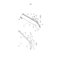
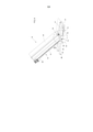
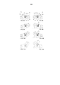
[0024] As características funcionais e de construção da correia transportadora de elevação com inclinação ajustável de acordo com a presente invenção serão mais bem compreendidas a partir da descrição detalhada abaixo, na qual se faz referência às figuras anexas, que representam uma de suas realizações preferidas, mas não limitadoras, nas quais: - a Figura 1 representa esquematicamente uma vista lateral de uma correia transportadora de elevação com inclinação ajustável de acordo com a presente invenção; - a Figura 2 representa esquematicamente uma vista axonométrica da correia transportadora de elevação de acordo com a presente invenção; - a Figura 3 representa uma vista seccional esquemática de acordo com um plano vertical da correia transportadora de elevação da Figura 1; - a Figura 4 representa esquematicamente uma vista em perspectiva de baixo da correia transportadora de elevação de acordo com a presente invenção, parcialmente explodida para exibir os componentes internos; - a Figura 5 representa uma vista axonométrica esquemática parcialmente explodida de cima da correia transportadora; - as Figuras 6 e 7 representam esquematicamente dois detalhes ampliados, respectiva mente, da Figura 5 (detalhe H) e da Figura 4 (detalhe K); e - as Figuras 8A e 8B, 9A e 9B, 10A e 10B, 11A e 11B representam, de acordo com uma vista lateral frontal e posterior, configurações angulares diferentes de um elemento de ajuste da inclinação da correia transportadora de acordo com a presente invenção.[0024] The functional and construction characteristics of the elevating conveyor belt with adjustable inclination in accordance with the present invention will be better understood from the detailed description below, in which reference is made to the attached figures, which represent one of his preferred achievements , but not limiting, in which: - Figure 1 schematically represents a side view of an elevating conveyor belt with adjustable inclination according to the present invention; Figure 2 schematically represents an axonometric view of the lifting conveyor belt according to the present invention; Figure 3 represents a schematic sectional view according to a vertical plane of the lifting conveyor belt of Figure 1; Figure 4 schematically represents a perspective view from below of the elevating conveyor belt according to the present invention, partially exploded to show the internal components; Figure 5 represents a schematic axonometric view partially exploded from above the conveyor belt; Figures 6 and 7 schematically represent two details enlarged, respectively, of Figure 5 (detail H) and Figure 4 (detail K); and - Figures 8A and 8B, 9A and 9B, 10A and 10B, 11A and 11B represent, according to a front and rear side view, different angular configurations of an inclination adjustment element of the conveyor belt according to the present invention. .
[0025] Com relação às figuras mencionadas acima, a correia transportadora de elevação com inclinação ajustável de acordo com a presente invenção, indicada como um todo por 10, compreende uma estrutura geralmente metálica definida por uma estrutura 12 que, na realização preferida de acordo com as figuras, compreende pelo menos duas seções adjacentes 14 e 16, restritas reciproca mente por meio de uma conexão articulada 13 de acordo com os métodos descritos abaixo e dispostas de acordo com um plano horizontal (seção horizontal 14 ou seção de carga) e de acordo com um plano em inclinação (seção de elevação 16).[0025] With respect to the figures mentioned above, the elevating conveyor belt with adjustable inclination according to the present invention, indicated as a whole by 10, comprises a generally metallic structure defined by a
[0026] A estrutura da seção horizontal 14 ou seção de carga compreende duas bordas opostas 14', enquanto a seção de elevação 16 compreende duas bordas opostas 16', com as mencionadas bordas opostas 14' e 16' enrijecidas por meio de elementos transversais 21.[0026] The structure of the
[0027] A estrutura 12 deve ser de tamanho apropriado em função do material (produtos finalizados, semiacabados ou similares) movido e, consequentemente, das cargas e das tensões estáticas e dinâmicas às quais a correia transportadora é submetida durante a sua operação.[0027] The
[0028] Além disso, a mencionada estrutura 12 é fixada de forma estável ao chão por meio de uma base fixa e montantes, com altura opcionalmente ajustável ou, como esquematizado nas figuras, por meio de montantes 18 (com altura ajustável) fixados a uma base 20 móvel por meio de rodas 22 ou meios equivalentes.[0028] In addition, the
[0029] A mencionada armação tem a função de manter e enrijecer a estrutura da correia transportadora.[0029] The aforementioned frame has the function of maintaining and tightening the structure of the conveyor belt.
[0030] Com relação às figuras e considerando a seção horizontal 14 ou seção de carga como elemento frontal e a seção de elevação como elemento posterior, a armação 12 compreende uma polia de motor 24 fixada de forma giratória à seção de elevação 26 correspondente à sua extremidade posterior e uma polia guia 26 fixada de forma giratória à seção horizontal 14 correspondente à sua extremidade frontal; em que a mencionada polia do motor 24 e a polia guia 26 são dispostas entre as bordas opostas 14' e 16' das duas seções 14 e 16 e transversalmente a elas.[0030] With respect to the figures and considering the
[0031] A polia do motor 24 é girada por meio de um motor elétrico 25 (opcionalmente equipado com uma unidade de redução), enquanto a polia guia 26 é uma polia ociosa, para determinar o movimento deslizante de uma correia 28 enrolada e tensionada sobre essas polias.[0031] The
[0032] Além disso, a armação 12 pode compreender elementos definidos, por exemplo, pelos rolamentos transversais de rotação ociosos ou por elementos similares a placas, posicionados para apoiar o deslizamento da correia 28 para definir substancialmente uma superfície de deslizamento adequada para assegurar estabilidade aprimorada dos produtos transportados pela mesma correia.[0032] In addition, the
[0033] Como introduzido acima, a seção horizontal 14 ou seção de carga e a seção de elevação 16 são restritas reciproca mente por meio de uma conexão articulada 13 que compreende duas placas horizontais opostas 30 fixadas correspondentemente à extremidade posterior da seção horizontal 14 ou seção de carga e duas placas de elevação opostas 32 fixadas correspondentemente à extremidade frontal da seção de elevação 16, com as mencionadas placas opostas 30 e 32 fixadas às bordas das armações das seções horizontal e de elevação por um meio de contenção de parafuso ou de tipo similar.[0033] As introduced above, the
[0034] As placas horizontais opostas 30 e as placas de elevação opostas 32 são acopladas entre si (com as placas de elevação opostas 32 dispostas internamente às placas horizontais opostas 30) correspondentemente às porções posteriores opostas às de fixação com relação às bordas opostas da armação 12 das duas seções para definir um ponto de apoio ou articulação que compreende um par coaxial de rolamentos opostos 31 (geralmente, embora não exclusiva mente, rolamentos de esfera) que suportem a rotação ociosa de um rolamento de apoio 34 disposto de forma transversal aos pares opostos de placas 30 e 32; em que o mencionado rolamento de apoio 34 é disposto de maneira inferior à correia 28 e, como definido acima, produz um apoio para o deslizamento da mencionada correia.[0034] The opposite
[0035] As placas opostas 30 e 32 compreendem ranhuras 36 com desenvolvimento retilíneo que se cruzam entre si adequadamente para definir a posição de dois rolamentos de retorno opostos 38 voltados para a parte interna das placas 30 e 32 na direção da correia 28 e com o eixo disposto paralelo e acima do eixo do rolamento de apoio 34; o rolamento de retorno 38 está em contato com a superfície superior da correia 28 e desliza em uma posição intermediária entre os mencionados rolamentos de retorno 38 e o mencionado rolamento de apoio 34.[0035] The
[0036] As placas horizontais opostas combinadas 30 e as placas de elevação 32 compreendem ranhuras adicionais 40, com desenvolvimento retilíneo, equipadas com uma escala graduada 42 (formada sobre a face externa das placas visível para o operador) para a função descrita em mais detalhes abaixo; transversal e internamente a ela, é disposto um elemento de contenção definido por um parafuso de fixação 40' que tem a função de fixar de maneira rígida os pares de placas opostas e impedir movimentos de rotação relativa entre eles.[0036] The combined opposing
[0037] O desenvolvimento longitudinal das ranhuras 36 e das ranhuras adicionais 40 é calculado para permitir alteração da inclinação da seção de elevação 16 com relação à seção horizontal 14 ou seção de carga em um intervalo angular y (calculado com referência a uma superfície horizontal) geralmente de 15° a 60°, como esquematizado nas Figuras 8A a 11B.[0037] The longitudinal development of the
[0038] O método de ajuste da inclinação da correia transportadora descrita em detalhes acima com relação às características de construção é detalhado abaixo.[0038] The method of adjusting the inclination of the conveyor belt described in detail above with respect to the construction characteristics is detailed below.
[0039] Caso uma mudança na inclinação da seção de elevação 16 seja necessária, o operador afrouxa os parafusos de fixação 40' e quaisquer elementos de parada 46 dos montantes 18 da armação 12 que bloqueiam a mudança da altura dos mencionados montantes 18 e, por meio da escala graduada 42, ajustam de forma precisa a inclinação da seção de elevação 16 com relação à seção horizontal 14 ou seção de carga no valor angular desejado, com o rolamento de retorno 38 e os parafusos de fixação 40', e deslizam com relação às ranhuras 36 e às ranhuras adicionais 40, como esquematizado nas Figuras 8A a 11B.[0039] If a change in the inclination of the
[0040] Após atingir a posição angular necessária, o parafuso de fixação 40' das placas opostas 30 e 32 e os elementos de parada 46 dos montantes 18 da armação 12 são fixados para impedir todos os movimentos de rotação relativos entre a seção horizontal ou seção de carga 14 e a seção de elevação 16.[0040] After reaching the required angular position, the fixing screw 40 'of the
[0041] Particularmente, durante a etapa de ajuste da inclinação da seção de elevação 16, a posição angular do rolamento de retorno 38 varia ao longo de uma trajetória retilínea (determinada pela forma das ranhuras 36) com amplitude angular definida por um ângulo a, calculado com referência à vertical traçada a partir do centro do rolamento 31 e igual à bissetriz do ângulo y; desta maneira, é possível manter a tensão constante da correia 28 com a mudança da inclinação da seção de elevação 16 com relação à horizontal ou seção de carga 14.[0041] Particularly, during the inclination adjustment step of the
[0042] Como pode ser percebido acima, as vantagens obtidas pela correia transportadora de acordo com a presente invenção são evidentes.[0042] As can be seen above, the advantages obtained by the conveyor belt according to the present invention are evident.
[0043] Devido à conexão articulada descrita, a correia transportadora de elevação com inclinação ajustável de acordo com a presente invenção permite, convenientemente, uma mudança rápida, fácil e precisa da inclinação da correia transportadora, de forma a adaptar a correia transportadora a configurações de layout diferentes.[0043] Due to the articulated connection described, the elevating conveyor belt with adjustable inclination according to the present invention conveniently allows a quick, easy and precise change of the inclination of the conveyor belt, in order to adapt the conveyor belt to configurations of different layout.
[0044] Uma vantagem adicional é representada pelo fato de que os rolamentos de retorno opostos 38, por meio de alteração da sua posição durante o ajuste da inclinação da seção de elevação ao longo de uma linha retilínea, asseguram a tensão constante da correia 28, evitando a formação de "saliências", sem a necessidade de apertá-los ou afrouxá-los com um meio acessório com a mudança de inclinação.[0044] An additional advantage is represented by the fact that the
[0045] Outra vantagem é representada pelo rolamento de apoio 34 que, disposto de forma coaxial à articulação definida pelas placas opostas 30 e 32, permite que o número de componentes da correia transportadora seja reduzido e que a sua construção seja simplificada.[0045] Another advantage is represented by the support bearing 34 which, arranged coaxially to the joint defined by the
[0046] Uma vantagem adicional é o fato de que a correia transportadora de acordo com a presente invenção possui estrutura modular que permite a expansão da estrutura descrita com relação à realização principal exibida nas figuras por meio da adição de seções horizontal e/ou de inclinação em série.[0046] An additional advantage is the fact that the conveyor belt according to the present invention has a modular structure that allows the expansion of the structure described with respect to the main realization shown in the figures by adding horizontal and / or tilting sections in series.
[0047] Embora não ilustradas nas figuras anexas, sobre a correia 28 normalmente são fornecidas, em função do tipo de produto transportado, tiras transversais adequadas para apoiar a produção durante a transferência.[0047] Although not illustrated in the attached figures, on the
[0048] Embora a presente invenção tenha sido descrita acima com relação particularmente a uma de suas realizações fornecida somente por meio de exemplos não limitadores, diversas modificações e variantes do relatório descritivo acima serão evidentes para os técnicos no assunto. Portanto, a presente invenção pretende incluir todas as modificações e variantes que se enquadrem dentro do escopo das reivindicações anexas.[0048] Although the present invention has been described above with particular regard to one of its realizations provided only by way of non-limiting examples, several modifications and variants of the above specification will be apparent to those skilled in the art. Therefore, the present invention is intended to include all modifications and variants that fall within the scope of the appended claims.
Claims (6)
Applications Claiming Priority (2)
| Application Number | Priority Date | Filing Date | Title |
|---|---|---|---|
| IT001705A ITMI20131705A1 (en) | 2013-10-15 | 2013-10-15 | ADJUSTABLE LIFTING CONVEYOR BELT |
| ITMI2013A001705 | 2013-10-15 |
Publications (2)
| Publication Number | Publication Date |
|---|---|
| BR102014025552A2 BR102014025552A2 (en) | 2015-09-22 |
| BR102014025552B1 true BR102014025552B1 (en) | 2020-12-15 |
Family
ID=49585540
Family Applications (1)
| Application Number | Title | Priority Date | Filing Date |
|---|---|---|---|
| BR102014025552-4A BR102014025552B1 (en) | 2013-10-15 | 2014-10-14 | elevating conveyor belt with adjustable tilt and tilt adjustment method |
Country Status (10)
| Country | Link |
|---|---|
| US (1) | US9334120B2 (en) |
| EP (1) | EP2862820B1 (en) |
| BR (1) | BR102014025552B1 (en) |
| CA (1) | CA2867398C (en) |
| DK (1) | DK2862820T3 (en) |
| ES (1) | ES2597244T3 (en) |
| IT (1) | ITMI20131705A1 (en) |
| MX (1) | MX352404B (en) |
| PL (1) | PL2862820T3 (en) |
| PT (1) | PT2862820T (en) |
Families Citing this family (35)
| Publication number | Priority date | Publication date | Assignee | Title |
|---|---|---|---|---|
| JP6076993B2 (en) * | 2012-09-26 | 2017-02-08 | 株式会社日立ハイテクノロジーズ | Sample transport device and specimen inspection automation system |
| NL2014878B1 (en) * | 2015-05-28 | 2017-01-31 | De Greef's Wagen- Carrosserie- En Machb B V | Filling device for filling a container with fragile products and method thereof. |
| CN105645042B (en) * | 2015-07-09 | 2017-10-27 | 徐工集团工程机械股份有限公司 | Fold and tensioning apparatus and ribbon conveyer |
| CN105819159A (en) * | 2016-05-24 | 2016-08-03 | 浙江新市油脂股份有限公司 | Novel belt conveying device |
| CN107187822A (en) * | 2017-07-14 | 2017-09-22 | 苏州双祺自动化设备有限公司 | General-purpose loads and unloads Extensible belt conveyor |
| CN107187803A (en) * | 2017-07-14 | 2017-09-22 | 苏州双祺自动化设备有限公司 | Adjustable docking height formula conveying telescopic machine |
| CN107826604A (en) * | 2017-11-20 | 2018-03-23 | 重庆庆研机电设备有限公司 | A kind of conveyer belt of adjustable folding angle |
| CN107963437A (en) * | 2017-11-20 | 2018-04-27 | 重庆庆研机电设备有限公司 | A kind of high-altitude conveyer belt system |
| CN108128597B (en) * | 2018-01-10 | 2024-03-15 | 江苏徐工工程机械研究院有限公司 | Folding, discharge height adjustment and belt tensioning devices and belt conveyors |
| US10947051B2 (en) * | 2018-01-23 | 2021-03-16 | Stephenson Technologies Inc. | Conveyor system assembly |
| CN108249107A (en) * | 2018-03-22 | 2018-07-06 | 上海晟哲机械科技有限公司 | A kind of automation climbing conveyer |
| CN109178826B (en) * | 2018-06-30 | 2020-10-02 | 绍兴柯桥兴旺印纸印花有限公司 | Be used for commodity circulation transportation discharge devices of being convenient for categorised |
| CN108928599B (en) * | 2018-08-09 | 2023-10-27 | 华南新海(深圳)科技股份有限公司 | Folding type channel conveyor |
| CN109160221A (en) * | 2018-08-29 | 2019-01-08 | 高国梁 | A kind of sugar refining technology transmission device |
| CN109225893B (en) * | 2018-10-25 | 2024-05-28 | 安徽拓力工程材料科技有限公司 | Device for sorting glass beads |
| CN109647722A (en) * | 2019-02-25 | 2019-04-19 | 王军 | A kind of logistics category filter equipment |
| CN110127493A (en) * | 2019-05-31 | 2019-08-16 | 奥帝亚电梯有限公司 | A kind of convenient transportation cargo to elevator device |
| CN110406874A (en) * | 2019-07-30 | 2019-11-05 | 苏州市永固金属制品有限公司 | A kind of high level based on intelligent compact shelf is got in stocks auxiliary device |
| CN110371614A (en) * | 2019-08-06 | 2019-10-25 | 马鞍山天高智能科技有限公司 | A kind of high-power semiconductor high-speed laser assembly line |
| CN110654896A (en) * | 2019-10-15 | 2020-01-07 | 界首市金龙机械设备有限公司 | Multifunctional loading and unloading conveyor |
| CN111099294A (en) * | 2019-12-28 | 2020-05-05 | 马腾 | Conveying equipment and method for treating heavy metal lead and zinc in soil by using block chain technology |
| CN110980188A (en) * | 2019-12-28 | 2020-04-10 | 马捷 | Device and method for lifting dried lake water bottom mud powder by using block chain technology |
| CN111573151A (en) * | 2020-05-19 | 2020-08-25 | 湖南穗丰食品有限公司 | Frozen food conveying device |
| CN112209021A (en) * | 2020-09-29 | 2021-01-12 | 杭州英木科技有限公司 | Slope-adjustable belt conveyor |
| KR102297520B1 (en) * | 2020-10-12 | 2021-09-02 | (주)삼성텍 | Welding automation system using heterogeneous nut of metal product for electric and combustion vehicle |
| CN112278910B (en) * | 2020-11-09 | 2022-08-19 | 安徽信息工程学院 | Bag type fertilizer conveyer convenient to adjust |
| CN113697351B (en) * | 2021-09-02 | 2023-04-14 | 美凌格智能装备(深圳)有限公司 | Multifunctional multi-channel efficient intelligent sorting system |
| CN113859860A (en) * | 2021-10-19 | 2021-12-31 | 江苏伟创塑胶制品有限公司 | Continuous transfer device of plastic bottle production usefulness |
| CN114455260B (en) * | 2021-12-13 | 2025-04-11 | 中铁十六局集团电气化工程有限公司 | A device for transporting earthwork from underground engineering |
| CN114455303A (en) * | 2022-01-12 | 2022-05-10 | 滁州市精美家电设备股份有限公司 | Adjustable supporting equipment for multi-station production line |
| CN114408506A (en) * | 2022-01-26 | 2022-04-29 | 胡伟 | A safe unloading platform for chemical production based on artificial intelligence |
| CN114789980B (en) * | 2022-04-24 | 2023-08-25 | 华能伊敏煤电有限责任公司 | Device for replacing upper carrier roller |
| CN114735446A (en) * | 2022-05-11 | 2022-07-12 | 中建新越建设工程有限公司 | Receiving device of building construction elevator |
| CN116729902A (en) * | 2023-05-26 | 2023-09-12 | 安徽星辉工业科技有限公司 | Conveying belt device with adjustable conveying height and working method thereof |
| CN116902477A (en) * | 2023-08-28 | 2023-10-20 | 合肥金果缘视觉科技有限公司 | Synchronous belt speed reducer |
Family Cites Families (7)
| Publication number | Priority date | Publication date | Assignee | Title |
|---|---|---|---|---|
| US4088255A (en) * | 1976-10-29 | 1978-05-09 | Ppg Industries, Inc. | Apparatus for opening lateral scores in moving glass sheets |
| US4367814A (en) * | 1977-07-20 | 1983-01-11 | Young Wendell M | Safety lift and tie-down apparatus for portable elevators and the like |
| DE3935175C2 (en) * | 1989-10-21 | 1995-04-20 | Axmann Foerdertechnik | Belt conveyor with two conveyor lines that can be set at an angle to each other |
| EP0731040B1 (en) * | 1995-03-04 | 1999-09-08 | MTF Technik Schürfeld GmbH & Co. KG | Articulated belt conveyor with defined tension of the support means |
| US7472785B2 (en) * | 2006-10-11 | 2009-01-06 | Kuhn North America, Inc. | Conveyor system with automatic incline |
| FR2956103B1 (en) * | 2010-02-09 | 2012-02-10 | Immequip | STRUCK STRAPPING STRUCTURE STRAPPING STRAPPING STRAP |
| US8622199B2 (en) * | 2010-12-23 | 2014-01-07 | Rite-Hite Holding Corporation | Adjustable conveyor extensions |
-
2013
- 2013-10-15 IT IT001705A patent/ITMI20131705A1/en unknown
-
2014
- 2014-10-07 PT PT141879551T patent/PT2862820T/en unknown
- 2014-10-07 DK DK14187955.1T patent/DK2862820T3/en active
- 2014-10-07 ES ES14187955.1T patent/ES2597244T3/en active Active
- 2014-10-07 EP EP14187955.1A patent/EP2862820B1/en active Active
- 2014-10-07 US US14/508,059 patent/US9334120B2/en active Active
- 2014-10-07 PL PL14187955T patent/PL2862820T3/en unknown
- 2014-10-10 MX MX2014012305A patent/MX352404B/en active IP Right Grant
- 2014-10-14 BR BR102014025552-4A patent/BR102014025552B1/en active IP Right Grant
- 2014-10-15 CA CA2867398A patent/CA2867398C/en active Active
Also Published As
| Publication number | Publication date |
|---|---|
| EP2862820A1 (en) | 2015-04-22 |
| PL2862820T3 (en) | 2017-04-28 |
| PT2862820T (en) | 2016-10-04 |
| US9334120B2 (en) | 2016-05-10 |
| ITMI20131705A1 (en) | 2015-04-16 |
| ES2597244T3 (en) | 2017-01-17 |
| US20150101910A1 (en) | 2015-04-16 |
| MX2014012305A (en) | 2015-04-29 |
| EP2862820B1 (en) | 2016-06-22 |
| BR102014025552A2 (en) | 2015-09-22 |
| DK2862820T3 (en) | 2016-10-03 |
| CA2867398C (en) | 2022-06-21 |
| CA2867398A1 (en) | 2015-04-15 |
| MX352404B (en) | 2017-11-22 |
Similar Documents
| Publication | Publication Date | Title |
|---|---|---|
| BR102014025552B1 (en) | elevating conveyor belt with adjustable tilt and tilt adjustment method | |
| BRPI0721877A2 (en) | process and apparatus for storing semi-finished tire products | |
| CN206827449U (en) | Transmission mechanism and medicine storage cabinet | |
| CN107697348B (en) | Intelligent logistics sorting system based on Internet of Things | |
| CN110091905A (en) | A kind of shipment bar device conducive to preform shipment safety | |
| KR20210029509A (en) | Apparatus for box casing | |
| CN111301928B (en) | Conveying device and conveyor with same | |
| CN219362366U (en) | Material conveying device with guiding function for processing bed board furniture | |
| CN205365682U (en) | Simple and easy goods conveyor | |
| IT202100005171A1 (en) | DEVICE FOR SEPARATING A LOAD FROM THE PALLET THAT SUPPORTS IT | |
| CN218706980U (en) | Clamp steering device and conveying equipment | |
| CN215477697U (en) | A logistics conveyor that is easy to adjust the curvature of the conveyor belt | |
| CN118545523A (en) | A retractable large crawler type grain scraper | |
| CN113060570B (en) | Mechanical automation applies to discharge devices of material transportation | |
| CN214140088U (en) | Conveying system | |
| CN109027569A (en) | A kind of intelligent console | |
| KR101128350B1 (en) | Conveyor facility | |
| CN217101627U (en) | Conveyer and storage workbin | |
| CN223836494U (en) | A blocking mechanism for a wheeled conveyor | |
| CN209024825U (en) | Automatic retractable wheel device and washing machine comprising same | |
| CN207914079U (en) | The automatic UV curing apparatus of display pannel | |
| CN119460487B (en) | Telescopic belt conveyor for warehouse center | |
| CN120573324A (en) | Battery transfer distance variable device | |
| JP2017088377A (en) | Conveyor posture change device | |
| CN221392404U (en) | Tire unloading roller way device of tire vulcanizer and vulcanizing machine production system |
Legal Events
| Date | Code | Title | Description |
|---|---|---|---|
| B03A | Publication of a patent application or of a certificate of addition of invention [chapter 3.1 patent gazette] | ||
| B06F | Objections, documents and/or translations needed after an examination request according [chapter 6.6 patent gazette] | ||
| B06U | Preliminary requirement: requests with searches performed by other patent offices: procedure suspended [chapter 6.21 patent gazette] | ||
| B09A | Decision: intention to grant [chapter 9.1 patent gazette] | ||
| B16A | Patent or certificate of addition of invention granted [chapter 16.1 patent gazette] |
Free format text: PRAZO DE VALIDADE: 20 (VINTE) ANOS CONTADOS A PARTIR DE 14/10/2014, OBSERVADAS AS CONDICOES LEGAIS. |