BR102012017339B1 - column device for sewing - Google Patents
column device for sewing Download PDFInfo
- Publication number
- BR102012017339B1 BR102012017339B1 BR102012017339-5A BR102012017339A BR102012017339B1 BR 102012017339 B1 BR102012017339 B1 BR 102012017339B1 BR 102012017339 A BR102012017339 A BR 102012017339A BR 102012017339 B1 BR102012017339 B1 BR 102012017339B1
- Authority
- BR
- Brazil
- Prior art keywords
- main
- launcher
- differential
- feeder
- connecting rod
- Prior art date
Links
Images


Landscapes
- Sewing Machines And Sewing (AREA)
Abstract
DISPOSITIVO DE COLUNA PARA COSTURA. Um dispositivo de coluna para costura compreendendo um mecanismo dotado de um eixo principal, um mecanismo de acionamento do lançador, um mecanismo longitudinal de acionamento do lançador, um mecanismo protetor de agulhas, um conjunto aumentador e um conjunto de coluna, capaz de gerar um movimento diferencial desigual ou variado entre o mecanismo aumentador principal e o mecanismo alimentador diferencial a fim de proporcionar um espaço de manobra mais conveniente e maior eficiência em materiais que exigem menor raio de giro quando a operação de costura é executada na máquina de costura de coluna.COLUMN DEVICE FOR SEWING. A sewing column device comprising a mechanism with a main axis, a launcher drive mechanism, a longitudinal launcher drive mechanism, a needle guard mechanism, an auger assembly and a column assembly, capable of generating movement uneven or varied differential between the main auger mechanism and the differential feed mechanism in order to provide a more convenient operating space and greater efficiency in materials that require less turning radius when the sewing operation is performed on the column sewing machine.
Description
[001] A presente invenção se refere a um dispositivo de coluna (postbed) para costura, mais especificamente a presente invenção se refere a uma combinação mecânica compreendendo um mecanismo dotado de um eixo principal, um mecanismo de acionamento do lançador (looper), um mecanismo longitudinal de acionamento do lançador, um mecanismo protetor de agulhas, um conjunto alimentador e um conjunto da coluna, combinação mecânica esta destinada a máquinas de costura de coluna para proporcionar um melhor espaço de operação na costura de materiais de tamanho reduzido ou muito estreitos que requerem menor raio de giro, sendo particularmente adequada para máquinas de costura stretch (para tecidos elásticos) com estrutura mecânica de coluna.[001] The present invention relates to a column device (postbed) for sewing, more specifically the present invention relates to a mechanical combination comprising a mechanism with a main axis, a drive mechanism for the launcher (looper), a longitudinal launcher drive mechanism, a needle guard mechanism, a feeder assembly and a column assembly, a mechanical combination intended for column sewing machines to provide a better operating space when sewing small or very narrow materials that they require less turning radius, being particularly suitable for stretch sewing machines (for elastic fabrics) with mechanical column structure.
[002] Com o avanço de modernas inovações mecânicas, a máquina de costura tem desempenhado um papel muito importante na produção de variados produtos na indústria da moda. Em um ambiente tão globalizado, as máquinas de costura têm sido projetadas para desenvolver alta velocidade e operar de forma multifuncional, precisa e inteligente. Atualmente, a máquina de costura stretch é conhecida como uma máquina de uso geral para costurar tecidos stretch (elásticos), e é própria para trabalhar produtos com boa elasticidade, extensão, planicidade e baixa perda de fio.[002] With the advancement of modern mechanical innovations, the sewing machine has played a very important role in the production of various products in the fashion industry. In such a globalized environment, sewing machines have been designed to develop high speed and operate in a multifunctional, precise and intelligent way. Currently, the stretch sewing machine is known as a general purpose machine for sewing stretch fabrics (elastic), and is suitable for working with products with good elasticity, extension, flatness and low thread loss.
[003] A costura de tecido stretch é geralmente feita com pelo menos duas agulhas e um lançador para formar uma costura plana sobre o tecido elástico e ainda assim permitir uma boa elasticidade. Portanto, a máquina de costura stretch tem sido utilizada em muitas operações de costura. Entretanto, quando a operação envolve materiais ou desenhos especiais com pequeno espaço para a costura ou com raio de giro limitado, a máquina de costura stretch tradicional não consegue executar bem suas funções. Ao contrário, ela apresenta um padrão de costura fraco e o material costurado não fica perfeitamente plano.[003] The sewing of stretch fabric is usually done with at least two needles and a launcher to form a flat seam on the elastic fabric and still allow good elasticity. Therefore, the stretch sewing machine has been used in many sewing operations. However, when the operation involves special materials or designs with small sewing space or with limited turning radius, the traditional stretch sewing machine cannot perform its functions well. On the contrary, it has a weak seam pattern and the sewn material is not perfectly flat.
[004] Assim, a presente invenção visa proporcionar um dispositivo de costura que pode ser configurado na máquina de costura stretch e resolver os problemas acima mencionados e seus inconvenientes.[004] Thus, the present invention aims to provide a sewing device that can be configured on the stretch sewing machine and to solve the above mentioned problems and their drawbacks.
[005] Nesse sentido, o objetivo principal da presente invenção é proporcionar um dispositivo de coluna para costura com uma combinação mecânica compreendendo um mecanismo dotado de um eixo principal, um mecanismo de acionamento do lançador, um mecanismo longitudinal de acionamento do lançador, um mecanismo protetor de agulhas, um conjunto alimentador e um conjunto da coluna, capaz de gerar um movimento diferencial desigual ou variado entre o mecanismo alimentador principal e o mecanismo alimentador diferencial a fim de proporcionar um espaço de manobra mais conveniente e maior eficiência em materiais que exigem menor raio de giro quando a operação de costura é executada na máquina de costura de coluna.[005] In this sense, the main objective of the present invention is to provide a sewing column device with a mechanical combination comprising a mechanism equipped with a main axis, a mechanism for launching the drive, a longitudinal mechanism for driving the launcher, a mechanism needle guard, a feeder assembly and a column assembly, capable of generating an uneven or varied differential movement between the main feeder mechanism and the differential feeder mechanism in order to provide a more convenient operating space and greater efficiency in materials that require less turning radius when the sewing operation is performed on the column sewing machine.
[006] A presente invenção se refere a um dispositivo de coluna para costura que compreende um mecanismo dotado de um eixo principal, um mecanismo de acionamento do lançador, um mecanismo longitudinal de acionamento do lançador, um mecanismo protetor de agulhas, um conjunto alimentador e um conjunto da coluna, onde o mecanismo do eixo principal é configurado com um eixo principal para entregar a potência mecânica e se conectar com o mecanismo de acionamento do lançador configurado com um lançador; o mecanismo longitudinal de acionamento do lançador é conectado com o eixo principal e tem um movimento mecânico simultâneo com o mecanismo de acionamento do lançador para ativar o movimento do lançador no sentido longitudinal; o mecanismo protetor de agulhas é conectado com o eixo principal e é configurado com o suporte do mecanismo protetor de agulhas de forma a proteger o movimento das agulhas; o conjunto alimentador está conectado ao eixo principal e compreende ainda um mecanismo alimentador principal e um mecanismo alimentador diferencial que se move para cima e para baixo levando o material de costura para frente; o conjunto da coluna configurado sob a forma de um cilindro serve para acomodar o mecanismo de acionamento do lançador, o mecanismo longitudinal de acionamento do lançador, o mecanismo protetor de agulhas e o conjunto alimentador, sendo ainda configurado com uma coluna, uma placa da garganta (throat plate) no topo da coluna e um mecanismo de corte sob a placa da garganta para realizar a operação de corte.[006] The present invention relates to a column seam device that comprises a mechanism with a main axis, a mechanism for launching the drive, a longitudinal mechanism for activating the launcher, a protective mechanism for needles, a feeder assembly and a column assembly, where the main shaft mechanism is configured with a main shaft to deliver mechanical power and connect with the launcher drive mechanism configured with a launcher; the longitudinal mechanism for launching the launcher is connected to the main shaft and has a mechanical movement simultaneous with the mechanism for launching the launcher to activate the movement of the launcher in the longitudinal direction; the needle guard mechanism is connected to the main shaft and is configured with the support of the needle guard mechanism in order to protect the movement of the needles; the feeder assembly is connected to the main shaft and further comprises a main feeder mechanism and a differential feeder mechanism that moves up and down, taking the sewing material forward; the column assembly configured in the form of a cylinder serves to accommodate the launcher's drive mechanism, the longitudinal launcher's drive mechanism, the needle guard mechanism and the feeder set, and it is also configured with a column, a throat plate (throat plate) at the top of the column and a cutting mechanism under the throat plate to perform the cutting operation.
[007] Através da combinação mecânica e da montagem do conjunto, a presente invenção proporciona um novo dispositivo que fornece um espaço de manobra conveniente para materiais de costura com tamanho reduzido, assim como para aqueles materiais que exigem menor raio de giro.[007] Through mechanical combination and assembly of the set, the present invention provides a new device that provides a convenient operating space for sewing materials with small size, as well as for those materials that require less turning radius.
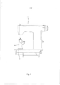
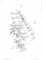
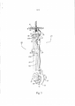
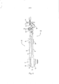
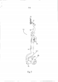
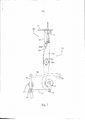
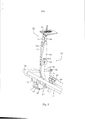
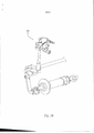
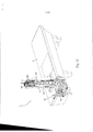
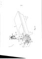
[008] A presente invenção poderá ser perfeitamente compreendida a partir da descrição detalhada que se segue e da configuração preferível tendo como referência os desenhos que a acompanham, onde: A Fig. 1 é uma vista esquemática mostrando a presente invenção configurada para uma máquina de costura de coluna; A Fig. 2 ilustra uma vista esquemática mostrando os principais componentes da presente invenção; A Fig. 3 é uma vista esquemática mostrando a combinação do mecanismo de acionamento do lançador e o mecanismo longitudinal de acionamento do lançador; A Fig. 4 representa uma vista esquemática mostrando a combinação do mecanismo de acionamento do lançador e o mecanismo longitudinal de acionamento do lançador de um ângulo diferente; A Fig. 5 é uma vista esquemática mostrando a estrutura conjugada do mecanismo protetor de agulhas; A Fig. 6 é uma vista esquemática mostrando a estrutura conjugada do conjunto alimentador; A Fig. 7 apresenta uma vista esquemática mostrando a estrutura conjugada do mecanismo alimentador diferencial; A Fig. 8 é uma vista esquemática mostrando a estrutura conjugada do mecanismo alimentador principal; A Fig. 9 é uma vista esquemática mostrando os componentes do conjunto da coluna; A Fig. 10 é uma vista esquemática mostrando a combinação do mecanismo de corte; A Fig. 11 ilustra uma vista esquemática mostrando uma combinação da presente invenção e a mesa de costura; e A Fig. 12 é uma vista esquemática mostrando outra combinação da presente invenção e a mesa de costura.[008] The present invention can be perfectly understood from the detailed description that follows and the preferred configuration with reference to the accompanying drawings, where: Fig. 1 is a schematic view showing the present invention configured for a machine column seam; Fig. 2 illustrates a schematic view showing the main components of the present invention; Fig. 3 is a schematic view showing the combination of the launcher's drive mechanism and the longitudinal launcher's drive mechanism; Fig. 4 represents a schematic view showing the combination of the launcher's drive mechanism and the longitudinal launcher's drive mechanism from a different angle; Fig. 5 is a schematic view showing the conjugated structure of the needle guard mechanism; Fig. 6 is a schematic view showing the combined structure of the feeder assembly; Fig. 7 shows a schematic view showing the conjugated structure of the differential feed mechanism; Fig. 8 is a schematic view showing the conjugated structure of the main feed mechanism; Fig. 9 is a schematic view showing the components of the column assembly; Fig. 10 is a schematic view showing the combination of the cutting mechanism; Fig. 11 illustrates a schematic view showing a combination of the present invention and the sewing table; and Fig. 12 is a schematic view showing another combination of the present invention and the sewing table.
[009] Descreveremos a seguir os desenhos das Figs. 1 a 12. A presente invenção se refere a um dispositivo de costura de coluna, compreende um mecanismo dotado de um eixo principal 10, um mecanismo de acionamento do lançador 20, um mecanismo longitudinal de acionamento do lançador 30, um mecanismo protetor de agulhas 40, um conjunto alimentador 50 e um conjunto da coluna 80, onde o mecanismo do eixo principal 10 é configurado com um eixo principal 11 para entregar a potência mecânica e se conectar com o mecanismo de acionamento do lançador 20 configurado com um lançador 28; o mecanismo longitudinal de acionamento do lançador 30 é conectado com o eixo principal 11 e tem um movimento mecânico simultâneo com o mecanismo de acionamento do lançador 20 para ativar o movimento do lançador 28 no sentido longitudinal; o mecanismo protetor de agulhas 40 é conectado com o eixo principal 11 e é configurado com o suporte do mecanismo protetor de agulhas 46 de forma a proteger o movimento das agulhas; o conjunto alimentador 50 está conectado ao eixo principal 11 e compreende ainda um mecanismo alimentador principal 60 e um mecanismo alimentador diferencial 70 que se move para cima e para baixo levando o material de costura para frente; o conjunto da coluna 80 configurado sob a forma de um cilindro serve para acomodar o mecanismo de acionamento do lançador 20, o mecanismo longitudinal de acionamento do lançador 30, o mecanismo protetor de agulhas 40 e o conjunto alimentador 50, sendo ainda configurado com uma coluna 82, uma placa da garganta 81 no topo da coluna 82 e um mecanismo de corte 83 sob a placa da garganta 81 para realizar a operação de corte.[009] We will describe in the following the drawings of Figs. 1 to 12. The present invention relates to a column sewing device, it comprises a mechanism provided with a
[010] O mecanismo de acionamento do lançador 20 também é configurado com um eixo excêntrico de acionamento 21, um rolamento 22, uma alça de acionamento 23, uma biela de ligação 24, uma junta universal 25, uma biela móvel 26, um assento do lançador 27 e um lançador 28, onde o eixo excêntrico de acionamento 21 é configurado de forma conjugada com o eixo principal 11 para receber a força mecânica. A alça de acionamento 23 é uma alça oca redonda para acomodar o rolamento 22 e receber o eixo excêntrico de acionamento 21. A parte superior da alça de acionamento 23 é configurada como um encaixe 231 para receber a biela de ligação 24 que é presa com um pino 241. A biela de ligação 24 é instalada com uma junta universal 25 numa extremidade. A biela móvel 26 é configurada com um furo axial 261 na extremidade superior e um furo 262 na extremidade inferior. A junção do furo axial 261 com o assento do lançador 27 e a junta universal 25 se dá através do furo inferior 262. O lançador 28 é fixado no assento do lançador 27 com um parafuso 271.[010] The drive mechanism of the
[011] O mecanismo longitudinal de acionamento do lançador 30 também é configurado com um eixo longitudinal de acionamento do lançador 31, um calço do lançador 32, uma biela do lançador 33, um suporte 34, um calço deslizante 35, um eixo do lançador 36, um tubo de apoio 37 e um fixador do eixo 38, onde o eixo longitudinal de acionamento do lançador 31 e o calço do lançador 32 se ajustam ao eixo principal 11 e a parte inferior da biela do lançador 33 forma uma fenda 331 que se encaixa no calço do lançador 32. A parte intermediária da biela do lançador 33 é configurada com uma ranhura deslizante 332 que acomoda o calço deslizante 35. O dito calço deslizante 35 se encaixa no suporte 34 com um parafuso 341 e o suporte 34 é fixado na coluna 82. A extremidade superior da biela do lançador 33 é configurada com uma estrutura em forma de Y 333 que é conectada ao fixador do eixo 38 com um parafuso de 381. O eixo do lançador 36 penetra através do tubo de apoio 37, do fixador do eixo 38, da biela móvel 26, do assento lançador 27 e do tubo de apoio 37 para permitir um movimento conjunto.[011] The longitudinal drive mechanism of the
[012] O mecanismo protetor de agulhas 10 também é configurado com um eixo de acionamento do protetor de agulhas 41, um calço deslizante do protetor de agulhas 42, uma biela de ligação do protetor de agulhas 43, um pino de apoio 44, um assento de apoio 45, um suporte do protetor de agulhas 46 e um protetor de agulhas 47, onde o eixo de acionamento do protetor de agulhas 41 e o calço deslizante do protetor de agulhas 42 são configurados para se encaixar no eixo principal 11. A parte inferior da biela de ligação do protetor de agulhas 43 forma uma fenda 431 que se encaixa no calço deslizante do protetor de agulhas 42. O protetor de agulhas 47 é fixado no suporte do protetor de agulhas 46 o qual se conecta com a biela de ligação do protetor de agulhas 43. A parte central da biela de ligação do protetor de agulhas 43 é configurada com um orifício 432 para permitir a passagem do pino de apoio 44 numa extremidade. A outra extremidade do pino de apoio 44 é introduzida no assento de apoio 45 que é firmemente fixado na coluna 82.[012] The
[013] O mecanismo alimentador principal 60 do conjunto alimentador 50 também é configurado com um eixo de acionamento do alimentador high-low (alto-baixo) 61, uma biela alimentadora principal 62, um parafuso alimentador principal 63, uma base alimentadora principal 64, um suporte 65, um cão alimentador principal 66, um braço de ligação principal 67, um braço de acionamento principal 68 e um eixo alimentador de saída 69, onde o eixo de acionamento do alimentador high-low 61 e a biela alimentadora principal 62 são configurados para se encaixar no eixo principal 11. A parte inferior da base alimentadora principal 64 é configurada com um furo 641. Os dois lados do braço de ligação principal 67 também são configurados com furos 671 e 672 para permitir que o parafuso alimentador principal 63 penetre através do furo 641 na parte inferior da base alimentadora principal 64, do furo 671 numa extremidade do braço de ligação principal 67 e da biela alimentadora principal 62 para permitir um movimento conjunto. A base alimentadora principal 64 é configurada com uma abertura 642 para permitir que o eixo de apoio 734 penetre através do calço alimentador principal 643 e se fixe firmemente no suporte 65 que é preso na coluna 82. A parte superior da base alimentadora principal 64 é configurada com uma ranhura guia 644 para permitir que o cão alimentador principal 66 seja preso na ranhura guia 644 com o parafuso 661 e ajustar a altura do cão alimentador principal 66 na ranhura guia 644. O furo 672 na outra extremidade do braço de ligação principal 67 é configurado para se unir ao braço de acionamento principal 68 por meio do parafuso 681. O braço de acionamento principal 68 é então conectado juntamente com o eixo alimentador de saída 69 para ter um movimento de ligação. O mecanismo alimentador diferencial 70 do conjunto alimentador 50 também é configurado com uma biela alimentadora diferencial 71, um pino alimentador diferencial 72, uma base alimentadora diferencial 73, um calço alimentador diferencial 741, um cão alimentador diferencial 74, uma primeira biela conectora diferencial 75, uma segunda biela conectora diferencial 76, um braço de acionamento diferencial 77, um braço de ajuste 78 e um eixo de ajuste 79, onde a biela alimentadora diferencial 71 é configurada para se encaixar no eixo principal 11. A parte inferior da base alimentadora diferencial 73 é configurada com um orifício. As duas extremidades da primeira biela conectora diferencial 75 são configuradas com furos 751 e 752 respectivamente para permitir que o pino alimentador diferencial 72 penetre através do furo 731 localizado na posição inferior da base alimentadora diferencial 73, do orifício 751 situado numa extremidade da primeira biela conectora diferencial 75 e da biela alimentadora diferencial 71 para permitir um movimento de ligação. Além disso, os dois lados da segunda biela conectora diferencial 76 são configurados com dois furos 761 e 762. A extremidade inferior do braço de acionamento diferencial 77 é configurada com um guia deslizante 771 para habilitar sua conexão com o furo 761 da segunda biela conectora diferencial 76 e com o outro furo 752 da primeira biela conectora diferencial 75 por meio de um parafuso 772. O braço de acionamento diferencial 77 é então conectado juntamente com o eixo alimentador de saída 69 para ter um movimento de ligação. O outro furo 762 da segunda biela conectora diferencial 76 liga o braço de ajuste 78 por meio de um parafuso 781. Outra extremidade do braço de ajuste 78 compreende uma conexão conjugada para ajustar o movimento mecânico. A parte superior da base alimentadora diferencial 73 é configurada com uma ranhura guia 732 para permitir que o cão alimentador diferencial 74 possa ser fixado firmemente na ranhura guia 732 por meio de um parafuso 742 e permitir o ajuste de sua altura na ranhura guia 732. A parte central da base alimentadora diferencial 73 é configurada com uma abertura 733 para permitir que o eixo de apoio 734 penetre através do calço alimentador diferencial 741 para formar um pivô e permitir um movimento de ligação.[013] The
[014] Descreveremos a seguir outros aspectos relativos aos desenhos das Figs. 1 a 12. A presente invenção se refere a um dispositivo de coluna para costura que é instalado numa placa de costura 2 de uma máquina de costura de coluna 1 (conforme ilustrado na Fig. 1) e uma das melhores configurações compreende um mecanismo dotado de um eixo principal 10, um mecanismo de acionamento do lançador 20, um mecanismo longitudinal de acionamento do lançador 30, um mecanismo protetor de agulhas 40, um conjunto alimentador 50 e um conjunto da coluna 80, onde o mecanismo do eixo principal 10 é configurado com um eixo principal 11 para entregar a potência mecânica e o mecanismo de acionamento do lançador 20 também é configurado com um eixo excêntrico de acionamento 21, um rolamento 22, uma alça de acionamento 23, uma biela de ligação 24, uma junta universal, uma biela móvel 26, um assento do lançador 27 e um lançador 28 (conforme ilustra a Fig.2), onde o eixo excêntrico de acionamento 21 é configurado de forma conjugada com o eixo principal 11 para receber a força mecânica. A alça de acionamento 23 é uma alça oca redonda para acomodar o rolamento 22 e receber o eixo excêntrico de acionamento 21. A parte superior da alça de acionamento 23 é configurada como um encaixe 231 para receber a biela de ligação 24 que é presa com um pino 241. A biela de ligação 24 é instalada com uma junta universal 25 numa extremidade. A biela móvel 26 é configurada com um furo axial 261 na extremidade superior e um furo 262 na extremidade inferior. A junção do furo axial 261 com o assento do lançador 27 e a junta universal 25 se dá através do furo inferior 262. O lançador 28 é fixado no assento do lançador 27 com um parafuso 271.[014] We will describe below other aspects related to the drawings in Figs. 1 to 12. The present invention relates to a column sewing device that is installed on a
[015] Assim, quando o eixo principal 11 atua sobre o eixo excêntrico de acionamento 21 ele transmite a força mecânica à biela móvel 26 através da conexão com a alça de acionamento 23, a biela de ligação 24 e a junta universal 25. Então, a biela móvel 26 permite que o lançador 28 se mova para frente e ao longo do eixo do lançador 36 (conforme ilustram as Figs. 3 ou 4). O mecanismo longitudinal de acionamento do lançador 30 também é configurado com um eixo longitudinal de acionamento do lançador 31, um calço do lançador 32, uma biela do lançador 33, um suporte 34, um calço deslizante 35, um eixo do lançador 36, um tubo de apoio 37 e um fixador do eixo 38 (conforme ilustra a Fig. 2), onde o eixo longitudinal de acionamento do lançador 31 e o calço do lançador 32 são configurados para se encaixar no eixo principal 11 e a parte inferior da biela do lançador 33 forma uma fenda 331 que se encaixa no calço do lançador 32. A parte intermediária da biela do lançador 33 é configurada com uma ranhura deslizante 332 que acomoda o calço deslizante 35. O dito calço deslizante 35 se encaixa no suporte 34 com um parafuso 341 e o suporte 34 é fixado na coluna 82. A extremidade superior da biela do lançador 33 é configurada com uma estrutura em forma de Y 333 que é conectada ao fixador do eixo 38 com um parafuso de 381. O eixo do lançador 36 penetra através do tubo de apoio 37, do fixador do eixo 38, da biela móvel 26, do assento do lançador 27 e do tubo de apoio 37 para permitir um movimento conjunto. Durante um ciclo do eixo longitudinal de acionamento do lançador 31, a força do movimento para cima e para baixo aciona o calço do lançador 32 e a força longitudinal é entregue através da biela do lançador 33. A parte intermediária da biela do lançador 33 é configurada com uma ranhura deslizante 332 que acomoda um calço deslizante 35. A biela do lançador 33 executa então um movimento cíclico no ponto pivotante do parafuso 341. A extremidade superior da biela do lançador 33 é configurada como uma estrutura em forma de Y 333 que é conectada ao fixador do eixo 38 com um parafuso de 381. Esta estrutura limita o movimento axial do fixador do eixo 38 e permite que o eixo lançador 36 faça apenas um movimento longitudinal para ativar o movimento do lançador 28 no assento do lançador 27 (conforme ilustram as Figs. 3 ou 4).[015] Thus, when the
[016] Além disso, o mecanismo protetor de agulhas 10 também é configurado com um eixo de acionamento do protetor de agulhas 41, um calço deslizante do protetor de agulhas 42, uma biela de ligação do protetor de agulhas 43, um pino de apoio 44, um assento de apoio 45, um suporte do protetor de agulhas 46 e um protetor de agulhas 47 (conforme ilustra a Fig.2), onde o eixo de acionamento do protetor de agulhas 41 e o calço deslizante do protetor de agulhas 42 são configurados para se encaixar no eixo principal 11. A parte inferior da biela de ligação do protetor de agulhas 43 forma uma fenda 331 que se encaixa no calço deslizante do protetor de agulhas 42. O protetor de agulhas 47 é fixado no suporte do protetor de agulhas 46 o qual se conecta com a biela de ligação do protetor de agulhas 43. A parte central da biela de ligação do protetor de agulhas 43 é configurada com um orifício 432 para permitir a passagem do pino de apoio 44 numa extremidade. A outra extremidade do pino de apoio 44 é introduzida no assento de apoio 45 que é firmemente fixado na coluna 82. Conforme o eixo de acionamento do protetor de agulhas 41 aciona a biela de ligação do protetor de agulhas 43 para executar o movimento de ligação, a biela de ligação do protetor de agulhas 43 faz com que o pino de apoio 44 se mova longitudinalmente como um pivô. Este mecanismo também faz com que o suporte do protetor de agulhas 46 configurado no topo da biela de ligação do protetor de agulhas 43 e o protetor de agulhas tenham um movimento longitudinal conjunto (conforme ilustra a Fig. 5).[016] In addition, the
[017] Além disso, o mecanismo alimentador principal 60 do conjunto alimentador 50 também é configurado com um eixo de acionamento do alimentador high-low 61, uma biela alimentadora principal 62, um parafuso alimentador principal 63, uma base alimentadora principal 64, um suporte 65, um cão alimentador principal 66, um braço de ligação principal 67, um braço de acionamento principal 68 e um eixo alimentador de saída 69 (conforme ilustra a Fig.2), onde o eixo de acionamento do alimentador high-low 61 e a biela alimentadora principal 62 são configurados para se encaixar no eixo principal 11. A parte inferior da base alimentadora principal 64 é configurada com um furo 641. Os dois lados do braço de ligação principal 67 também são configurados com furos 671 e 672 para permitir que o parafuso alimentador principal 63 penetre através do furo 641 na parte inferior da base alimentadora principal 64, do furo 671 numa extremidade do braço de ligação principal 67 e da biela alimentadora principal 62 para permitir um movimento conjunto. A base alimentadora principal 64 é configurada com uma abertura 642 para permitir que o eixo de apoio 734 penetre através do calço alimentador principal 643 e se fixe firmemente no suporte 65 que é preso na coluna 82. A parte superior da base alimentadora principal 64 é configurada com uma ranhura guia 644 para permitir que o cão alimentador principal 66 seja preso na ranhura guia 644 para permitir o cão alimentador principal 66 seja preso juntamente com a ranhura guia 644 com o parafuso 661 e ajustar a altura do cão alimentador principal 66 na ranhura guia 644. O furo 672 na outra extremidade do braço de ligação principal 67 é configurado para se unir ao braço de acionamento principal 68 por meio do parafuso 681. O braço de acionamento principal 68 é então conectado juntamente com o eixo alimentador de saída 69 para ter um movimento de ligação. Portanto, o eixo alimentador de saída 69 recebe a força motriz do eixo principal 11 e então entrega essa força através do braço de acionamento principal 68 e do braço de ligação principal 67 que tem uma extremidade conectada com a base alimentadora principal 64 através do parafuso alimentador principal 63. Isto faz com que a base alimentadora principal 64 execute um movimento longitudinal pelo pivô do eixo de apoio 734. O cão alimentador principal 66 que liga com a base alimentadora principal 64, pode ajustar a altura necessária na ranhura guia 644. Além disso, o eixo de acionamento do alimentador high-low 61 transmite a força mecânica para a base alimentadora principal 64 através da conexão com a biela alimentadora principal 62 e com parafuso alimentador principal 63. Ele permite que a base alimentadora principal 64 faça um movimento para cima e para baixo ao longo do calço alimentador principal 643, resultando num efeito alimentador por etapas (conforme ilustra a Fig. 8).[017] In addition, the
[018] O mecanismo alimentador diferencial 70 do conjunto alimentador 50 também é configurado com uma biela alimentadora diferencial 71, um pino alimentador diferencial 72, uma base alimentadora diferencial 73, um calço alimentador diferencial 741, um cão alimentador diferencial 74, uma primeira biela conectora diferencial 75, uma segunda biela conectora diferencial 76, um braço de acionamento diferencial 77, um braço de ajuste 78 e um eixo de ajuste 79 (conforme ilustra a Fig.2), onde a biela alimentadora diferencial 71 é configurada para se encaixar no eixo principal 11. A parte inferior da base alimentadora diferencial 73 é configurada com um orifício. As duas extremidades da primeira biela conectora diferencial 75 são configuradas com furos 751 e 752 respectivamente para permitir que o pino alimentador diferencial 72 penetre através do furo 731 localizado na posição inferior da base alimentadora diferencial 73, do orifício 751 situado numa extremidade da primeira biela conectora diferencial 75 e da biela alimentadora diferencial 71 para permitir um movimento de ligação. Além disso, os dois lados da segunda biela conectora diferencial 76 são configurados com dois furos 761 e 762. A extremidade inferior do braço de acionamento diferencial 77 é configurada com um guia deslizante 771 para habilitar sua conexão com o furo 761 da segunda biela conectora diferencial 76 e com o outro furo 752 da primeira biela conectora diferencial 75 por meio de um parafuso 772. O braço de acionamento diferencial 77 é então conectado juntamente com o eixo alimentador de saída 69 para ter um movimento de ligação. O outro furo 762 da segunda biela conectora diferencial 76 liga o braço de ajuste 78 por meio de um parafuso 781. Outra extremidade do braço de ajuste 78 compreende uma conexão conjugada para ajustar o movimento mecânico. A parte superior da base alimentadora diferencial 73 é configurada com uma ranhura guia 732 para permitir que o cão alimentador diferencial 74 possa ser fixado firmemente na ranhura guia 732 por meio de um parafuso 742 e permitir o ajuste de sua altura na ranhura guia 732. A parte central da base alimentadora diferencial 73 é configurada com uma abertura 733 para permitir que o eixo de apoio 734 penetre através do calço alimentador diferencial 741 para formar um pivô e permitir um movimento de ligação. Assim, a força do movimento do eixo alimentador de saída 69 pode ser transmitida ao braço de acionamento diferencial 77 para acionar a primeira biela conectora diferencial 75 ao longo da guia deslizante 771. Ela também altera o alcance do braço de acionamento diferencial 77 pelo movimento de ligação do braço de ajuste 78 e da segunda biela conectora diferencial 76. Consequentemente, a distância do movimento da base alimentadora diferencial 73 é alterada simultaneamente e gera um movimento diferencial com a base alimentadora principal 64 (conforme ilustra a Fig. 7).[018] The
[019] Por fim, o conjunto da coluna 80 configurado sob a forma de um cilindro é serve para acomodar o mecanismo de acionamento do lançador 20, o mecanismo longitudinal de acionamento do lançador 30, o mecanismo protetor de agulhas 40 e o conjunto alimentador de 50, sendo ainda configurado com uma coluna 82, uma placa da garganta 81 no topo da coluna 82 e um mecanismo de corte 83 sob a placa da garganta 81 para realizar a operação de corte.[019] Finally, the
[020] Através da combinação mecânica e da montagem do conjunto acima descrito, a presente invenção proporciona um novo dispositivo que fornece um espaço de manobra conveniente para materiais de costura com tamanho reduzido, assim como para aqueles materiais que exigem menor raio de giro.[020] By mechanically combining and assembling the assembly described above, the present invention provides a new device that provides a convenient operating space for small-sized sewing materials, as well as those materials that require a smaller turning radius.
[021] Vale destacar que as configurações apresentadas no presente relatório descritivo são meramente ilustrativas dos princípios da presente invenção e que uma grande variedade de modificações poderão ser efetuadas pelos peritos na arte sem se afastar do espírito e do escopo da presente invenção em conformidade com as apensas reivindicações.[021] It is worth noting that the configurations presented in this specification are merely illustrative of the principles of the present invention and that a wide variety of modifications may be made by those skilled in the art without departing from the spirit and scope of the present invention in accordance with the attached claims.
Claims (6)
Applications Claiming Priority (2)
| Application Number | Priority Date | Filing Date | Title |
|---|---|---|---|
| TW100125016 | 2011-07-14 | ||
| TW100125016A TW201303105A (en) | 2011-07-14 | 2011-07-14 | Columnar raised head sewing machine device |
Publications (2)
| Publication Number | Publication Date |
|---|---|
| BR102012017339A2 BR102012017339A2 (en) | 2014-04-29 |
| BR102012017339B1 true BR102012017339B1 (en) | 2021-01-19 |
Family
ID=48137952
Family Applications (1)
| Application Number | Title | Priority Date | Filing Date |
|---|---|---|---|
| BR102012017339-5A BR102012017339B1 (en) | 2011-07-14 | 2012-07-13 | column device for sewing |
Country Status (2)
| Country | Link |
|---|---|
| BR (1) | BR102012017339B1 (en) |
| TW (1) | TW201303105A (en) |
Families Citing this family (2)
| Publication number | Priority date | Publication date | Assignee | Title |
|---|---|---|---|---|
| CN104233656B (en) * | 2014-09-17 | 2016-10-19 | 深圳市远成缝纫机工业有限公司 | Sewing machine and automatic thread trimming device thereof |
| TWI796759B (en) * | 2021-08-18 | 2023-03-21 | 星菱縫機股份有限公司 | High post bed sewing machine |
Family Cites Families (4)
| Publication number | Priority date | Publication date | Assignee | Title |
|---|---|---|---|---|
| TW587116B (en) * | 2003-04-30 | 2004-05-11 | Shing Ling Sewing Machine Co L | Transmission and adjustment structure for cranking shaft of sewing machine feeder |
| TWI238209B (en) * | 2004-08-13 | 2005-08-21 | Chee Siang Ind Co Ltd | High-column type sewing machine |
| KR101364557B1 (en) * | 2007-06-07 | 2014-02-19 | 주식회사 썬스타 | Stitch skip equipment of chain stitch sewing machine |
| TWM400487U (en) * | 2010-09-21 | 2011-03-21 | Ming Jang Sewing Machine Co Ltd | Driving mechanism of needle guard sewing machine |
-
2011
- 2011-07-14 TW TW100125016A patent/TW201303105A/en unknown
-
2012
- 2012-07-13 BR BR102012017339-5A patent/BR102012017339B1/en active IP Right Grant
Also Published As
| Publication number | Publication date |
|---|---|
| TW201303105A (en) | 2013-01-16 |
| TWI406987B (en) | 2013-09-01 |
| BR102012017339A2 (en) | 2014-04-29 |
Similar Documents
| Publication | Publication Date | Title |
|---|---|---|
| US11326284B2 (en) | Double-needle lockstitch sewing machine | |
| BRPI0902362A2 (en) | Sewing machine | |
| CN105436865B (en) | A kind of dowel driving machine structure | |
| BR102014008756A2 (en) | swivel needle threading mechanism | |
| BR112015031571B1 (en) | DEVICE FOR FEEDING YARN INTO THE NEEDLES OF A KNITTED LOOM AND A KNITTED LOOM FOR KNITTED ARTICLES, SOCKS OR SIMILAR | |
| JP5393743B2 (en) | Pillar type high head sewing machine | |
| TW201814099A (en) | Thread trimmer of post-bed sewing machine | |
| BR102012017339B1 (en) | column device for sewing | |
| JP4769534B2 (en) | Large presser for sewing machine | |
| US2830549A (en) | Shank button feeder | |
| TWI711734B (en) | Sewing machine with upper feeding stop mechanism | |
| CN207452444U (en) | A kind of embroidery machine purl structure | |
| CN106087288B (en) | Sewing machine and sewing machine needle protection device | |
| CN202528571U (en) | Injector needle cylinder scale mark pad printing machine | |
| CN1924138B (en) | Keyhole sartorius | |
| CN208533065U (en) | A kind of cambered surface feeding mechanism for sewing machine | |
| CN102168352A (en) | Paillette feeding device | |
| CN208776950U (en) | A kind of dual-needle-bar mechanism | |
| CN208219140U (en) | A kind of sewing machine feeding mechanism for stereo fabric sewing | |
| CN207525466U (en) | A kind of adjustable presser of embroidery machine | |
| US1588030A (en) | Needle-bar controlling device for sewing machines | |
| CN108360155A (en) | A kind of feeding adjustment structure for sewing machine | |
| JP2015188669A5 (en) | ||
| CN109097914B (en) | Stitch length adjusting mechanism of lockstitch sewing machine | |
| CN103850071A (en) | Band material embroidering and pleating device |
Legal Events
| Date | Code | Title | Description |
|---|---|---|---|
| B03A | Publication of an application: publication of a patent application or of a certificate of addition of invention | ||
| B06F | Objections, documents and/or translations needed after an examination request according art. 34 industrial property law | ||
| B06V | Preliminary requirement: requests without searches performed by other patent offices: suspension of the patent application procedure | ||
| B09A | Decision: intention to grant | ||
| B16A | Patent or certificate of addition of invention granted |
Free format text: PRAZO DE VALIDADE: 20 (VINTE) ANOS CONTADOS A PARTIR DE 13/07/2012, OBSERVADAS AS CONDICOES LEGAIS. |