KR101295004B1 - Exoskeleton mechanism for limb power assistance - Google Patents
Exoskeleton mechanism for limb power assistance Download PDFInfo
- Publication number
- KR101295004B1 KR101295004B1 KR1020110101430A KR20110101430A KR101295004B1 KR 101295004 B1 KR101295004 B1 KR 101295004B1 KR 1020110101430 A KR1020110101430 A KR 1020110101430A KR 20110101430 A KR20110101430 A KR 20110101430A KR 101295004 B1 KR101295004 B1 KR 101295004B1
- Authority
- KR
- South Korea
- Prior art keywords
- link
- frame
- motor
- fixed
- exoskeleton
- Prior art date
Links
Images


Classifications
-
- A—HUMAN NECESSITIES
- A63—SPORTS; GAMES; AMUSEMENTS
- A63B—APPARATUS FOR PHYSICAL TRAINING, GYMNASTICS, SWIMMING, CLIMBING, OR FENCING; BALL GAMES; TRAINING EQUIPMENT
- A63B21/00—Exercising apparatus for developing or strengthening the muscles or joints of the body by working against a counterforce, with or without measuring devices
- A63B21/005—Exercising apparatus for developing or strengthening the muscles or joints of the body by working against a counterforce, with or without measuring devices using electromagnetic or electric force-resisters
-
- A—HUMAN NECESSITIES
- A61—MEDICAL OR VETERINARY SCIENCE; HYGIENE
- A61H—PHYSICAL THERAPY APPARATUS, e.g. DEVICES FOR LOCATING OR STIMULATING REFLEX POINTS IN THE BODY; ARTIFICIAL RESPIRATION; MASSAGE; BATHING DEVICES FOR SPECIAL THERAPEUTIC OR HYGIENIC PURPOSES OR SPECIFIC PARTS OF THE BODY
- A61H1/00—Apparatus for passive exercising; Vibrating apparatus ; Chiropractic devices, e.g. body impacting devices, external devices for briefly extending or aligning unbroken bones
- A61H1/02—Stretching or bending or torsioning apparatus for exercising
- A61H1/0274—Stretching or bending or torsioning apparatus for exercising for the upper limbs
- A61H1/0277—Elbow
-
- A—HUMAN NECESSITIES
- A61—MEDICAL OR VETERINARY SCIENCE; HYGIENE
- A61F—FILTERS IMPLANTABLE INTO BLOOD VESSELS; PROSTHESES; DEVICES PROVIDING PATENCY TO, OR PREVENTING COLLAPSING OF, TUBULAR STRUCTURES OF THE BODY, e.g. STENTS; ORTHOPAEDIC, NURSING OR CONTRACEPTIVE DEVICES; FOMENTATION; TREATMENT OR PROTECTION OF EYES OR EARS; BANDAGES, DRESSINGS OR ABSORBENT PADS; FIRST-AID KITS
- A61F2/00—Filters implantable into blood vessels; Prostheses, i.e. artificial substitutes or replacements for parts of the body; Appliances for connecting them with the body; Devices providing patency to, or preventing collapsing of, tubular structures of the body, e.g. stents
- A61F2/50—Prostheses not implantable in the body
- A61F2/68—Operating or control means
- A61F2/70—Operating or control means electrical
-
- A—HUMAN NECESSITIES
- A63—SPORTS; GAMES; AMUSEMENTS
- A63B—APPARATUS FOR PHYSICAL TRAINING, GYMNASTICS, SWIMMING, CLIMBING, OR FENCING; BALL GAMES; TRAINING EQUIPMENT
- A63B21/00—Exercising apparatus for developing or strengthening the muscles or joints of the body by working against a counterforce, with or without measuring devices
- A63B21/06—User-manipulated weights
- A63B21/065—User-manipulated weights worn on user's body
-
- B—PERFORMING OPERATIONS; TRANSPORTING
- B25—HAND TOOLS; PORTABLE POWER-DRIVEN TOOLS; MANIPULATORS
- B25J—MANIPULATORS; CHAMBERS PROVIDED WITH MANIPULATION DEVICES
- B25J9/00—Programme-controlled manipulators
- B25J9/0006—Exoskeletons, i.e. resembling a human figure
-
- B—PERFORMING OPERATIONS; TRANSPORTING
- B25—HAND TOOLS; PORTABLE POWER-DRIVEN TOOLS; MANIPULATORS
- B25J—MANIPULATORS; CHAMBERS PROVIDED WITH MANIPULATION DEVICES
- B25J9/00—Programme-controlled manipulators
- B25J9/003—Programme-controlled manipulators having parallel kinematics
- B25J9/0072—Programme-controlled manipulators having parallel kinematics of the hybrid type, i.e. having different kinematics chains
-
- A—HUMAN NECESSITIES
- A61—MEDICAL OR VETERINARY SCIENCE; HYGIENE
- A61H—PHYSICAL THERAPY APPARATUS, e.g. DEVICES FOR LOCATING OR STIMULATING REFLEX POINTS IN THE BODY; ARTIFICIAL RESPIRATION; MASSAGE; BATHING DEVICES FOR SPECIAL THERAPEUTIC OR HYGIENIC PURPOSES OR SPECIFIC PARTS OF THE BODY
- A61H2201/00—Characteristics of apparatus not provided for in the preceding codes
- A61H2201/12—Driving means
- A61H2201/1207—Driving means with electric or magnetic drive
- A61H2201/1215—Rotary drive
-
- A—HUMAN NECESSITIES
- A61—MEDICAL OR VETERINARY SCIENCE; HYGIENE
- A61H—PHYSICAL THERAPY APPARATUS, e.g. DEVICES FOR LOCATING OR STIMULATING REFLEX POINTS IN THE BODY; ARTIFICIAL RESPIRATION; MASSAGE; BATHING DEVICES FOR SPECIAL THERAPEUTIC OR HYGIENIC PURPOSES OR SPECIFIC PARTS OF THE BODY
- A61H2201/00—Characteristics of apparatus not provided for in the preceding codes
- A61H2201/14—Special force transmission means, i.e. between the driving means and the interface with the user
- A61H2201/1481—Special movement conversion means
- A61H2201/149—Special movement conversion means rotation-linear or vice versa
-
- A—HUMAN NECESSITIES
- A61—MEDICAL OR VETERINARY SCIENCE; HYGIENE
- A61H—PHYSICAL THERAPY APPARATUS, e.g. DEVICES FOR LOCATING OR STIMULATING REFLEX POINTS IN THE BODY; ARTIFICIAL RESPIRATION; MASSAGE; BATHING DEVICES FOR SPECIAL THERAPEUTIC OR HYGIENIC PURPOSES OR SPECIFIC PARTS OF THE BODY
- A61H2201/00—Characteristics of apparatus not provided for in the preceding codes
- A61H2201/16—Physical interface with patient
- A61H2201/1602—Physical interface with patient kind of interface, e.g. head rest, knee support or lumbar support
- A61H2201/165—Wearable interfaces
-
- A—HUMAN NECESSITIES
- A61—MEDICAL OR VETERINARY SCIENCE; HYGIENE
- A61H—PHYSICAL THERAPY APPARATUS, e.g. DEVICES FOR LOCATING OR STIMULATING REFLEX POINTS IN THE BODY; ARTIFICIAL RESPIRATION; MASSAGE; BATHING DEVICES FOR SPECIAL THERAPEUTIC OR HYGIENIC PURPOSES OR SPECIFIC PARTS OF THE BODY
- A61H2201/00—Characteristics of apparatus not provided for in the preceding codes
- A61H2201/50—Control means thereof
- A61H2201/5007—Control means thereof computer controlled
-
- A—HUMAN NECESSITIES
- A61—MEDICAL OR VETERINARY SCIENCE; HYGIENE
- A61H—PHYSICAL THERAPY APPARATUS, e.g. DEVICES FOR LOCATING OR STIMULATING REFLEX POINTS IN THE BODY; ARTIFICIAL RESPIRATION; MASSAGE; BATHING DEVICES FOR SPECIAL THERAPEUTIC OR HYGIENIC PURPOSES OR SPECIFIC PARTS OF THE BODY
- A61H2201/00—Characteristics of apparatus not provided for in the preceding codes
- A61H2201/50—Control means thereof
- A61H2201/5058—Sensors or detectors
- A61H2201/5061—Force sensors
Abstract
본 발명은 사지의 근력을 보조하기 위한 외골격장치에 관한 것으로서, 특히 모터 구동에 따른 사지의 근력 운동뿐만 아니라 작동 시에 순응성 부여를 통해 사용자의 안전성 및 각 관절에 작용하는 힘을 측정할 수 있도록 구성한 것이다.
상기와 같은 목적을 달성하기 위한 본 발명에 따른 근력보조를 위한 외골격장치는 사지의 상부 골격과 대응하여 위치하는 고정 프레임과, 사지의 하부 골격과 대응하여 위치하며 고정 프레임에 힌지부로 결합되어 상하방향으로 회전하는 회전 프레임과, 사지의 말단부를 받쳐주는 받침 프레임과, 고정 프레임에 장착되며 회전 프레임에 연결되어 회전 프레임이 상하방향으로 회전하도록 구동하는 제1모터와, 회전 프레임에 장착되어 받침 프레임에 연결되며 받침 프레임이 상하방향과 좌우방향으로의 회전 및 하부 골격의 축(롤축)을 기준으로 회전하도록 구동하는 모터들과, 제1모터와 회전 프레임을 연결하는 링크들과, 모터들과 받침 프레임을 연결하는 링크들을 포함하는 것을 기술적 특징으로 한다.The present invention relates to an exoskeleton device for assisting the muscle strength of the limbs, and in particular configured to measure the safety of the user and the force acting on each joint through the provision of compliance in operation as well as the muscle movement of the limbs according to the motor drive. will be.
Exoskeletal device for muscle strength support according to the present invention for achieving the above object is a fixed frame positioned to correspond to the upper skeleton of the limbs, and corresponding to the lower skeleton of the limbs are coupled to the hinge to the fixed frame in the vertical direction Rotation frame rotated to the end, the support frame for supporting the distal end of the limb, the first motor is mounted to the fixed frame and connected to the rotation frame to drive the rotation frame to rotate in the vertical direction, and the support frame is mounted to the rotation frame Motors connected to the support frame so that the support frame rotates in the vertical and horizontal directions and rotates about the axis of the lower frame (roll axis), links connecting the first motor and the rotation frame, the motors and the support frame It includes a technical feature to include links connecting the.

Description
본 발명은 사지의 근력을 보조하기 위한 외골격장치에 관한 것으로서, 특히 모터 구동에 따른 사지의 근력 운동뿐만 아니라 작동 시에 순응성 부여를 통해 사용자의 안전성 및 각 관절에 작용하는 힘을 측정할 수 있도록 구성한 것이다.
The present invention relates to an exoskeleton device for assisting the muscle strength of the limbs, and in particular configured to measure the safety of the user and the force acting on each joint through the provision of compliance in operation as well as the muscle movement of the limbs according to the motor drive. will be.
사지의 움직임이 불편한 환자의 팔 또는 다리에 장착되어 환자의 근력을 보조하거나 또는 근력을 강화시키기 위한 외골격장치가 개발되고 있다.Exoskeletal devices have been developed to assist the patient's muscle strength or strengthen the muscle strength by being mounted on the arm or leg of the patient in which the limb movement is inconvenient.
외골격장치는 사지(아래에서는 '팔'로 통칭하여 설명함)의 골격과 대응하는 프레임이 팔의 근육 움직임이 원활하게 움직일 수 있도록 구성되는데, 팔의 움직임과 동일한 움직임이 가능하도록 복수의 프레임과 링크 그리고 구동에 필요한 모터를 구비한다.The exoskeleton is composed of a frame corresponding to the skeleton of the limb (hereinafter referred to as 'arm') so that the muscle movement of the arm can move smoothly. And a motor required for driving.
한편, 팔이 불편한 환자에게 장착되어 사용됨에 따라 외골격장치는 착용이 간편하고 또한 응급 시에 탈착이 용이하도록 구성되어야 하며, 환자에게 무리한 힘이 가해지지 않도록 정밀한 작동과 정밀한 감지가 필요하다.On the other hand, as the arm is mounted on an uncomfortable patient, the exoskeleton should be configured to be easy to wear and to be easily removable in an emergency, and requires precise operation and precise detection so as not to apply excessive force to the patient.
도면에서, 도 1은 아래의 선행기술문헌에 공개된 상지근력보조를 위한 외골격장치를 나타낸 사진이다.In the drawings, Figure 1 is a photograph showing the exoskeleton device for upper extremity muscle strength disclosed in the prior art document below.
도 1에 도시된 바와 같이, 종래의 외골격장치는 링 형태의 가이드레일을 사용함에 따라 환자가 착용 및 탈착하기에 어려움이 있으며, 링 형태의 가이드레일을 사용함에 따라 외골격장치의 부피가 커서 환자가 움직임에 간섭되기 쉬어 위험하다는 단점이 있다.As shown in Figure 1, the conventional exoskeleton device is difficult to wear and detach the patient according to the use of the ring-shaped guide rail, the volume of the exoskeleton device is large by the patient using the ring-shaped guide rail The disadvantage is that it is easy to interfere with the movement.
또한 링크를 연결하는 모터가 프레임의 측방향으로 돌출되게 형성됨에 따라 외골격장치의 부피가 클 뿐만 아니라 외골격장치의 설계에 어려움이 있다.
In addition, since the motor connecting the link is formed to protrude in the lateral direction of the frame, there is a difficulty in designing the exoskeleton as well as the volume of the exoskeleton.
본 발명은 앞에서 설명한 바와 같은 종래 기술의 문제점을 해결하기 위하여 발명된 것으로서, 환자가 착용하기에 편리하며 또한 응급 시에 탈착이 용이하도록 구성한 근력보조를 위한 외골격장치를 제공하는 데 그 목적이 있다.The present invention has been invented to solve the problems of the prior art as described above, an object of the present invention is to provide an exoskeleton device for muscle strength assistance, which is configured to be easy for the patient to wear and easy to detach in an emergency.
본 발명은 환자가 팔을 움직임에 있어 가해지는 힘을 측정할 수 있도록 구성한 근력보조를 위한 외골격장치를 제공하는 데 그 목적이 있다.It is an object of the present invention to provide an exoskeleton device for muscle strength assistance, which is configured to measure the force exerted by the patient on the movement of the arm.
본 발명은 팔을 지지하는 프레임의 길이방향으로 모터가 장착되어 프레임의 측부로 돌출된 구성이 없어 조밀하게 구성된 근력보조를 위한 외골격장치를 제공하는 데 그 목적이 있다.
An object of the present invention is to provide an exoskeleton device for muscle strength support, which is densely configured because the motor is mounted in the longitudinal direction of the frame supporting the arm and there is no configuration protruding to the side of the frame.
상기와 같은 목적을 달성하기 위한 본 발명에 따른 근력보조를 위한 외골격장치는 사지의 상부 골격과 대응하여 위치하는 고정 프레임과, 사지의 하부 골격과 대응하여 위치하며 고정 프레임에 힌지부로 결합되어 상하방향으로 회전하는 회전 프레임과, 고정 프레임에 장착되며 회전 프레임에 연결되어 회전 프레임이 상하방향으로 회전하도록 구동하는 제1모터와, 제1모터와 회전 프레임을 연결하는 링크들을 포함하는 것을 기술적 특징으로 한다.Exoskeletal device for muscle strength support according to the present invention for achieving the above object is a fixed frame positioned to correspond to the upper skeleton of the limbs, and corresponding to the lower skeleton of the limbs are coupled to the hinge to the fixed frame in the vertical direction It characterized in that it comprises a rotating frame rotating to the rotation, a first motor mounted to the fixed frame and connected to the rotating frame to drive the rotating frame to rotate in the vertical direction, and links connecting the first motor and the rotating frame. .
또한, 본 발명의 바람직한 실시예에 따르면, 제1모터의 회전축은 고정 프레임의 길이방향으로 위치한다.Further, according to a preferred embodiment of the present invention, the rotation axis of the first motor is located in the longitudinal direction of the fixed frame.
또한, 본 발명의 바람직한 실시예에 따르면, 제1모터의 회전축에는 제1경사축간 회전동력전달부의 구동기어가 장착되며, 구동기어와 연동하는 연동기어의 축에는 제1링크가 고정되고, 제1링크의 단부에는 제2링크의 단부가 힌지 결합되며 제2링크의 단부는 힌지부에 고정된다.In addition, according to a preferred embodiment of the present invention, the driving gear of the rotational power transmission unit between the first inclined shaft is mounted on the rotating shaft of the first motor, the first link is fixed to the shaft of the interlocking gear interlocked with the driving gear, An end of the second link is hinged to the end of the link and the end of the second link is fixed to the hinge portion.
또한, 본 발명의 바람직한 실시예에 따르면, 힌지부는 고정 프레임에 형성된 제1힌지 브래킷과, 회전 프레임과 연결되어 제1힌지 브래킷과 대응하며 힌지 축으로 상대 회전 가능하게 장착된 제2힌지 브래킷을 포함하며, 제2링크는 제2힌지 브래킷에 힌지 결합된다.In addition, according to a preferred embodiment of the present invention, the hinge portion includes a first hinge bracket formed on the fixed frame, and a second hinge bracket connected to the rotating frame to correspond to the first hinge bracket and rotatably mounted to the hinge axis. The second link is hinged to the second hinge bracket.
또한, 본 발명의 바람직한 실시예에 따르면, 제2힌지 브래킷에는 슬라이드 브래킷이 형성되고, 슬라이드 브래킷에는 회전 프레임의 길이방향으로 장공이 형성되며, 회전 프레임에 형성된 슬라이더가 장공에 끼워져 잠금되거나 잠금해제된 상태로 장공의 길이방향으로 이동 가능하다.In addition, according to a preferred embodiment of the present invention, the second hinge bracket is formed with a slide bracket, the slide bracket is formed with a long hole in the longitudinal direction of the rotating frame, the slider formed on the rotating frame is inserted into the long hole is locked or unlocked It is movable in the longitudinal direction of the long hole in a state.
본 발명에 따른 근력보조를 위한 외골격장치는 사지의 하부 골격과 대응하여 위치하는 회전 프레임과, 사지의 말단부를 받쳐주는 받침 프레임과, 회전 프레임에 장착되며 받침 프레임에 연결되어 받침 프레임이 상하방향과 좌우방향으로의 회전 및 하부 골격의 축(롤축)을 기준으로 회전하도록 구동하는 모터들과, 모터들과 받침 프레임을 연결하는 링크들을 포함하는 것을 기술적 특징으로 한다.Exoskeletal apparatus for muscle strength support according to the present invention is a rotation frame positioned corresponding to the lower skeleton of the limbs, a support frame for supporting the distal end of the limbs, mounted on the rotation frame and connected to the support frame is the support frame is up and down direction and Technical features include motors driven to rotate in the horizontal direction and to rotate about the axis of the lower frame (roll axis), and links connecting the motors and the support frame.
또한, 본 발명의 바람직한 실시예에 따르면, 상기 모터들은 받침 프레임이 좌우방향으로 회전하도록 구동하는 제2모터와, 받침 프레임이 상하방향으로 회전하도록 구동하는 제3모터와, 받침 프레임이 롤축을 중심으로 회전하도록 구동하는 제4모터를 포함하며, 제2모터, 제3모터 및 제4모터의 각 회전축은 받침 프레임의 길이방향으로 위치한다.According to a preferred embodiment of the present invention, the motors include a second motor for driving the support frame to rotate in the left and right directions, a third motor for driving the support frame to rotate in the up and down directions, and the support frame to the roll axis. It includes a fourth motor for driving to rotate, wherein the rotation axis of the second motor, the third motor and the fourth motor is located in the longitudinal direction of the support frame.
또한, 본 발명의 바람직한 실시예에 따르면, 제2모터의 회전축에는 제2경사축간 회전동력전달부의 구동기어가 장착되고, 구동기어와 연동하는 연동기어의 축에는 제3링크가 고정되며, 제3링크의 단부에는 제4링크의 일단부가 힌지 결합되고, 제5링크의 양단에는 회전조인트가 장착되며, 제4링크의 타단부는 제5링크의 한 쪽 회전조인트의 블록에 힌지 결합되며, 받침 프레임에는 제5링크의 다른 쪽 회전조인트의 블록이 고정된다.In addition, according to a preferred embodiment of the present invention, the drive shaft of the rotational power transmission unit between the second inclination shaft is mounted on the rotation shaft of the second motor, the third link is fixed to the shaft of the interlocking gear interlocked with the drive gear, One end of the fourth link is hinged to the end of the link, and a rotary joint is mounted at both ends of the fifth link, and the other end of the fourth link is hinged to a block of one rotary joint of the fifth link. The block of the other rotational joint of the fifth link is fixed to.
또한, 본 발명의 바람직한 실시예에 따르면, 제4링크의 타단부가 힌지 결합된 회전조인트의 블록에는 회전 프레임의 길이방향으로 제1가이드 바가 고정되고, 제1가이드 바는 회전 프레임에 고정된 제1홀더에 끼워져 직선 운동한다.In addition, according to a preferred embodiment of the present invention, the first guide bar is fixed in the longitudinal direction of the rotary frame to the block of the rotary joint hinged to the other end of the fourth link, the first guide bar is fixed to the rotary frame It fits in a holder and moves linearly.
또한, 본 발명의 바람직한 실시예에 따르면, 제3모터의 회전축에는 제3경사축간 회전동력전달부의 구동기어가 장착되고, 구동기어와 연동하는 연동기어의 축에는 제6링크가 고정되며, 제6링크의 단부에는 제7링크의 일단부가 힌지 결합되고, 제8링크의 양단에는 회전조인트가 장착되며, 제7링크의 타단부는 제8링크의 한 쪽 회전조인트의 블록에 힌지 결합되며, 받침 프레임에는 제8링크의 다른 쪽 회전조인트의 블록이 고정된다.In addition, according to a preferred embodiment of the present invention, the drive shaft of the rotational power transmission unit between the third inclined shaft is mounted to the rotary shaft of the third motor, the sixth link is fixed to the shaft of the interlocking gear interlocked with the drive gear, One end of the seventh link is hinged to an end of the link, and a rotary joint is mounted at both ends of the eighth link, and the other end of the seventh link is hinged to a block of one rotary joint of the eighth link. The block of the other rotary joint of the eighth link is fixed.
또한, 본 발명의 바람직한 실시예에 따르면, 제7링크의 타단부가 힌지 결합된 회전조인트의 블록에는 회전 프레임의 길이방향으로 제2가이드 바가 고정되고, 제2가이드 바는 회전 프레임에 고정된 제2홀더에 끼워져 직선 운동한다.In addition, according to a preferred embodiment of the present invention, the second guide bar is fixed to the block of the rotary joint hinged to the other end of the seventh link in the longitudinal direction of the rotating frame, the second guide bar is fixed to the rotating frame 2 It is inserted into the holder and moves linearly.
또한, 본 발명의 바람직한 실시예에 따르면, 제4모터의 단부에는 회전조인트가 장착되며, 회전조인트의 블록에 제9링크의 일단부가 고정되고, 제9링크의 타단부에는 제10링크의 일단부가 힌지 결합되며, 제10링크의 타단부는 받침 프레임에 힌지 결합된다.In addition, according to a preferred embodiment of the present invention, the end of the fourth motor is equipped with a rotary joint, one end of the ninth link is fixed to the block of the rotary joint, one end of the tenth link to the other end of the ninth link It is hinged and the other end of the tenth link is hinged to the supporting frame.
또한, 본 발명의 바람직한 실시예에 따르면, 제9링크의 일단부는 회전조인트의 블록에 형성된 축에 고정되며 축의 연장선과, 제9링크와 제10링크를 연결하는 힌지 축의 연장선 및 제10링크와 받침 프레임을 연결하는 힌지 축의 연장선은 한 점에서 만난다.Further, according to a preferred embodiment of the present invention, one end of the ninth link is fixed to the shaft formed in the block of the rotary joint and the extension line of the shaft, the extension line of the hinge shaft connecting the ninth link and the tenth link and the tenth link and the support The extension of the hinge axis connecting the frame meets at one point.
또한, 본 발명의 바람직한 실시예에 따르면, 받침 프레임은 상기 한 점을 중심으로 만곡된다.In addition, according to a preferred embodiment of the present invention, the support frame is curved about the one point.
또한, 본 발명의 바람직한 실시예에 따르면, 받침 프레임에는 손잡이가 장착되어 사지의 말단부인 손으로 손잡이를 파지한다.In addition, according to a preferred embodiment of the present invention, the support frame is equipped with a handle to grip the handle by the hand of the end of the limb.
또한, 본 발명의 바람직한 실시예에 따르면, 받침 프레임에는 고정수단이 장착되어 발을 고정수단으로 고정시킨다.In addition, according to a preferred embodiment of the present invention, the supporting frame is mounted with a fixing means to fix the foot to the fixing means.
또한, 본 발명의 바람직한 실시예에 따르면, 제1모터의 회전축에는 순응모듈인 유연 힌지가 각각 장착된다.In addition, according to a preferred embodiment of the present invention, the flexible shaft, which is a compliance module, is mounted on the rotating shaft of the first motor, respectively.
또한, 본 발명의 바람직한 실시예에 따르면, 제2모터, 제3모터, 제4모터의 각 회전축에는 순응모듈인 유연 힌지가 각각 장착된다.In addition, according to a preferred embodiment of the present invention, the flexible hinge, which is a compliant module, is mounted on each of the rotation shafts of the second motor, the third motor, and the fourth motor.
또한, 본 발명의 바람직한 실시예에 따르면, 상기 유연 힌지에는 스트레인 게이지가 장착되어 유연 힌지에 가해지는 응력을 측정한다.In addition, according to a preferred embodiment of the present invention, the flexible hinge is equipped with a strain gauge to measure the stress applied to the flexible hinge.
본 발명에 따른 근력보조를 위한 외골격장치는 사지의 상부 골격과 대응하여 위치하는 고정 프레임과, 사지의 하부 골격과 대응하여 위치하며 고정 프레임에 힌지부로 결합되어 상하방향으로 회전하는 회전 프레임과, 사지의 말단부를 받쳐주는 받침 프레임과, 고정 프레임에 장착되며 회전 프레임에 연결되어 회전 프레임이 상하방향으로 회전하도록 구동하는 제1모터와, 회전 프레임에 장착되며 받침 프레임에 연결되어 받침 프레임이 상하방향과 좌우방향으로의 회전 및 하부 골격의 축(롤축)을 기준으로 회전하도록 구동하는 모터들과, 제1모터와 회전 프레임을 연결하는 링크들과, 모터들과 받침 프레임을 연결하는 링크들을 포함하는 것을 기술적 특징으로 한다.
Exoskeletal apparatus for muscle strength support according to the present invention is a fixed frame positioned corresponding to the upper skeleton of the limbs, a rotation frame which is located in correspondence with the lower skeleton of the limbs and coupled to the hinge frame to rotate in the vertical direction, and the limbs A first motor mounted on the fixed frame and connected to the rotating frame to drive the rotating frame to rotate in the vertical direction; and a supporting frame mounted to the rotating frame and connected to the supporting frame to support the supporting frame. Rotation in the left and right direction, and the motor for driving to rotate about the axis (roll axis) of the lower frame, links for connecting the first motor and the rotation frame, and links for connecting the motor and the support frame It is technical feature.
앞서 설명한 바와 같이, 본 발명에 따른 근력보조를 위한 외골격장치는 고정 프레임과 회전 프레임의 저면에 구동모터들이 장착되고, 그 회전축이 고정 프레임 또는 회전 프레임의 길이방향으로 위치한다. 즉 외골격장치의 측방향으로 돌출된 모터의 구성이 없어 외골격장치의 전체 구성을 조밀하게 구성할 수 있으며, 작동 시에 환자와 부딪치는 문제점을 해결할 수 있다는 장점이 있다.As described above, in the exoskeleton device for muscle strength support according to the present invention, the driving motors are mounted on the bottom of the fixed frame and the rotating frame, and the rotating shaft is positioned in the longitudinal direction of the fixed frame or the rotating frame. That is, since there is no configuration of the motor protruding in the lateral direction of the exoskeleton device, the entire configuration of the exoskeleton device can be densely constructed, and there is an advantage in that the problem of hitting the patient during operation can be solved.
또한, 본 발명에 따른 근력보조를 위한 외골격장치는 고정 프레임과 회전 프레임 및 받침 프레임에 사지를 올릴 수 있게 구성됨으로써, 긴급 시에 환자가 사지를 외골격장치에서 신속하게 이탈시킬 수 있다는 장점이 있다.In addition, the exoskeleton device for muscle strength support according to the present invention is configured to raise the limbs on the fixed frame and the rotating frame and the supporting frame, there is an advantage that the patient can be quickly released from the exoskeleton device in an emergency.
또한, 본 발명에 따른 근력보조를 위한 외골격장치는 모터의 회전축에 순응모듈을 장착하여 과도한 힘을 완충하여 환자를 보호할 수 있고, 순응모듈에 스트레인 게이지를 장착하여 힘을 계산할 수 있다는 장점이 있다.In addition, the exoskeleton device for muscle strength support according to the present invention is equipped with a compliance module to the rotation axis of the motor to protect the patient by buffering excessive force, there is an advantage that can be calculated by mounting the strain gauge on the compliance module .
또한, 본 발명에 따른 근력보조를 위한 외골격장치는 고정 프레임의 양측으로 링크 및 고정 브래킷이 위치함으로써, 윗팔을 안정적으로 지지할 수 있다. 따라서 근력이 약한 환자가 외골격장치를 이용하여 팔을 움직일 때에 고정 프레임 밖으로 팔이 떨어지는 사고를 미연에 방지할 수 있다.
In addition, the exoskeleton device for muscle strength support according to the present invention can be stably supported by the upper arm by positioning the link and the fixing bracket on both sides of the fixed frame. Therefore, when the patient with weak muscle strength moves the arm using the exoskeleton, it is possible to prevent the accident that the arm falls out of the fixed frame.
도 1은 선행기술문헌에 공개된 상지근력보조를 위한 외골격장치를 나타낸 사진이다.
도 2는 본 발명에 따른 외골격장치를 착용한 상태를 나타낸 사시도이고,
도 3은 도 2에 도시된 외골격장치를 나타낸 저면 사시도이다.
도 4a 내지 도 4c는 외골격장치의 제1구동모터의 작동관계를 나타낸 사시도이고,
도 5a 내지 도 5c는 외골격장치의 제3구동모터의 작동관계를 나타낸 사시도이며,
도 6a 내지 도 6c는 외골격장치의 제2구동모터의 작동관계를 나타낸 사시도이다.
도 7a 내지 도 7c는 외골격장치의 제4구동모터의 작동관계를 나타낸 사시도이고,
도 8은 본 발명에 따른 외골격장치의 구동 메커니즘을 나타낸 개념도이며,
도 9는 구동모터에 장착된 순응모듈을 나타낸 개념도이다.1 is a photograph showing the exoskeleton device for upper extremity muscle strength disclosed in the prior art literature.
Figure 2 is a perspective view showing a state wearing the exoskeleton device according to the present invention,
3 is a bottom perspective view showing the exoskeleton shown in FIG.
4a to 4c are perspective views showing the operating relationship of the first driving motor of the exoskeleton device,
5a to 5c are perspective views showing the operation relationship of the third drive motor of the exoskeleton,
6A to 6C are perspective views illustrating an operation relationship of the second driving motor of the exoskeleton device.
7A to 7C are perspective views illustrating an operation relationship of a fourth driving motor of the exoskeleton device,
8 is a conceptual diagram showing a driving mechanism of the exoskeleton device according to the present invention,
9 is a conceptual diagram illustrating a compliance module mounted on a drive motor.
아래에서는 본 발명에 따른 근력보조를 위한 외골격장치의 양호한 실시예를 첨부한 도면을 참조로 하여 상세히 설명한다.Hereinafter, with reference to the accompanying drawings, preferred embodiments of the exoskeleton device for muscle strength support according to the present invention will be described in detail.
도면에서, 도 2는 본 발명에 따른 외골격장치를 착용한 상태를 나타낸 사시도이고, 도 3은 도 2에 도시된 외골격장치를 나타낸 저면 사시도이다. 그리고 도 4a 내지 도 4c는 외골격장치의 제1구동모터의 작동관계를 나타낸 사시도이고, 도 5a 내지 도 5c는 외골격장치의 제3구동모터의 작동관계를 나타낸 사시도이다. 도 6a 내지 도 6c는 외골격장치의 제2구동모터의 작동관계를 나타낸 사시도이며, 도 7a 내지 도 7c는 외골격장치의 제4구동모터의 작동관계를 나타낸 사시도이고, 도 8은 본 발명에 따른 외골격장치의 구동 메커니즘을 나타낸 개념도이며, 도 9는 구동모터에 장착된 순응모듈을 나타낸 개념도이다.2 is a perspective view showing a state wearing the exoskeleton device according to the invention, Figure 3 is a bottom perspective view showing the exoskeleton device shown in FIG. 4A to 4C are perspective views illustrating an operation relationship of the first driving motor of the exoskeleton device, and FIGS. 5A to 5C are perspective views illustrating an operation relationship of the third drive motor of the exoskeleton device. 6a to 6c is a perspective view showing the operation relationship of the second drive motor of the exoskeleton device, Figure 7a to 7c is a perspective view showing the operation relationship of the fourth drive motor of the exoskeleton device, Figure 8 is an exoskeleton according to the present invention A conceptual diagram showing a drive mechanism of the device, Figure 9 is a conceptual diagram showing a compliance module mounted on the drive motor.
도 2에 도시된 바와 같이, 외골격장치(100)는 위팔(상완골 부위)(1H)을 받쳐주는 고정 프레임(110)과, 아래팔(척골과 요골 부위)을 받쳐주는 회전 프레임(120)과, 손잡이(131)가 형성되며 손잡이(131)를 파지한 손을 받쳐주는 받침 프레임(130)을 포함하며, 고정 프레임(110)과 회전 프레임(120)은 힌지 결합된 힌지부(140)를 기준으로 회전 프레임(120)이 상하방향(Y축)으로 회전하며, 받침 프레임(130)은 회전 프레임(120)에 복수의 링크들로 연결되어 3자유도(X축,Y축, ROLL축)로 회전 구동한다.As shown in FIG. 2, the
아래에서는 이와 같이 구성된 외골격장치에 대해 구체적으로 설명한다.Hereinafter, the exoskeleton configured as described above will be described in detail.
도 3에 도시된 바와 같이, 고정 프레임(110)은 상완골이 있는 위팔(1H)과 대응하여 위치하며 고정 프레임(110)의 양측에는 고정 브래킷(111)이 상향으로 절곡되어 고정 브래킷(111)에 회전 프레임(120)이 힌지 결합된다. 여기에서 고정 프레임(110)에 위팔(1H)을 안착하면 고정 브래킷(111)의 사이에 위팔(1H)이 위치하며 팔꿈치는 고정 프레임(110)과 회전 프레임(120)의 사이 즉 힌지부(140)에 대응하여 위치한다.As shown in FIG. 3, the
그리고 회전 프레임(120)은 고정 프레임(110)의 고정 브래킷(111)에 힌지 결합되며, 회전 프레임(120)은 고정 프레임(110)을 기준으로 상하방향으로 회전 가능하다. The
한편, 힌지부(140)는 고정 브래킷(111)의 단부에 고정된 제1힌지 브래킷(141)과, 제1힌지 브래킷(141)과 대응하며 회전 프레임(120)에 고정된 제2힌지 브래킷(142)을 포함하며, 제1힌지 브래킷(141)과 제2힌지 브래킷(142)이 힌지 축(143)으로 연결된다.On the other hand, the
또한 제2힌지 브래킷(142)에는 회전 프레임(120)의 길이방향으로 장공(148)이 형성된 슬라이드 브래킷(147)이 형성되며, 회전 프레임(120)에 고정된 슬라이더(125)가 슬라이드 브래킷(147)의 장공(148)에 삽입되어 고정된다. 회전 프레임(120)의 슬라이더(125)가 슬라이드 브래킷(147)에 고정됨에 따라 고정 프레임(110)과 회전 프레임(120)의 간격은 고정되지만, 환자의 팔 길이에 따라 슬라이더(125)의 고정을 해체하고 슬라이드 브래킷(147)의 장공(148) 길이방향으로 슬라이더(125) 즉 회전 프레임(120)을 이동시켜 다른 지점에 고정함으로써, 상대적으로 팔이 긴 환자 또는 짧은 환자에 맞춰 회전 프레임(120)의 위치를 변경할 수 있다. 도면에는 도시하지 않았으나 슬라이드 브래킷의 길이방향으로 간격을 두고 구멍들을 형성하고 구멍에 볼트를 끼워 슬라이더에 형성된 암나사공에 볼트를 체결하여 슬라이더를 슬라이드 브래킷에 고정한다. 그리고 볼트를 풀어 고정을 해체한 후 슬라이더를 이동시켜 다른 지점의 구멍에 볼트로 끼워 슬라이더를 체결 고정할 수 있다.In addition, the
한편, 회전 프레임(120)을 회전시키는 제1구동모터(151)는 고정 프레임(110)의 저면에 장착되며, 고정 프레임(110)과 평행하게 위치한 제1구동모터(151)의 회전축(151S) 단부에는 제1베벨기어(161)가 장착된다. 제1베벨기어(161)는 제1구동모터(151)의 회전축(151S)에 고정된 구동기어(161D)와 구동기어(161D)에 맞물려 회전하는 연동기어(161C)를 포함하며, 연동기어(161C)에 고정된 축(161S)은 고정 프레임(110)에 회전 가능하게 장착된 상태로 축(161S)의 단부에 제1링크(171)의 일단부가 고정된다. 그리고 제1링크(171)의 타단부에는 L형 구조인 제2링크(172)의 일단이 힌지 결합되고, 제2링크(172)의 타단은 회전 프레임(120)에 고정된 제2힌지 브래킷(142)에 힌지 결합된다.On the other hand, the
따라서 제1구동모터(151)가 회전하면 제1베벨기어(161)의 연동기어(161C)의 축(161S)이 회전하면서 제1링크(171)는 축(161S)을 중심으로 회전하고 제2링크(172)는 제1링크(171)의 회전에 따라 연동하게 되는데, 이때 제2링크(172)의 타단에 힌지 결합된 제2힌지 브래킷(142)이 힌지 축(143)을 중심으로 회전하면서 회전 프레임(120)이 상하방향으로 회전하게 된다.Accordingly, when the
한편 회전 프레임(120)의 저면 양측에는 제2구동모터(152)와 제3구동모터(153)가 각각 장착된다.On the other hand, the
도 5a 내지 도 6c에 도시된 바와 같이, 제2구동모터(152)와 제3구동모터(153)의 회전축(152S, 153S)은 회전 프레임(120)과 평행하게 위치하며, 제2구동모터(152)의 회전축(152S)에는 제2베벨기어(162)가 장착되고, 제3구동모터(153)의 회전축(153S)에는 제3베벨기어(163)가 장착된다. 제2베벨기어(162) 및 제3베벨기어(163) 또한 회전축(152S, 153S)에 고정된 구동기어(도 6a의 162D, 도 5a의 163D)와, 구동기어(162D, 163D)에 맞물려 회전하는 연동기어(162C, 163C)를 포함하며, 연동기어(162C, 163C)에 고정된 축(162S, 163S)은 회전 프레임(120)에 회전 가능하게 장착된 상태로 축(162S, 163S)의 단부에는 링크(173, 176)의 일단이 고정된다. 여기에서 제2베벨기어(162)의 연동기어(162C)에 고정된 링크를 '제3링크(173)'라 하고, 제3베벨기어(163)의 연동기어(163C)에 고정된 링크를 '제6링크(176)'라 한다. 제3링크(173)는 회전 프레임(120)의 측부 상향으로 연장되고, 제4링크(174)는 회전 프레임(120)의 저면 폭 중앙 쪽으로 연장된다.As shown in FIGS. 5A to 6C, the
그리고 제3링크(173)의 타단에는 제4링크(174)의 일단이 힌지 결합되며 제4링크(174)는 전방 즉 손을 받쳐주는 받침 프레임(130)이 위치한 방향으로 연장된다. 또한 제6링크(176)의 타단에는 제7링크(177)의 일단이 힌지 결합되며 제7링크(177)는 전방으로 연장된다.One end of the
한편, 제4링크(174)의 타단에는 제5링크(175)가 힌지 결합된다. 제5링크(175)는 양단에 유니버설조인트(191)가 각각 장착된 링크로서, 제5링크(175)의 일단에 장착된 유니버설조인트 블록(191B)이 제4링크(174)의 타단과 힌지 결합된다. 그리고 양단에 유니버설조인트(192)가 각각 장착된 제8링크(178)가 제7링크(177)의 타단에 결합되는데, 제8링크(178)의 일단에 장착된 유니버설조인트 블록(192B)에 제7링크(177)의 타단이 힌지결합된다.Meanwhile, the
여기에서 제4링크(174) 및 제5링크(175)는 회전 프레임(120)의 길이방향으로 회전 프레임(120)의 측부에 위치하며, 제7링크(177)와 제8링크(178)는 회전 프레임(120)의 저면에 위치하되, 회전 프레임(120)의 폭 중앙에서 회전 프레임(120)의 길이방향으로 위치한다. Herein, the
그리고 제5링크(175)의 타단에 장착된 유니버설조인트 블록(191B)은 받침 프레임(130)에 고정되고, 제8링크(178)의 타단에 장착된 유니버설조인트 블록(192B) 또한 받침 프레임(130)에 고정된다.The universal
한편, 제4링크(174)가 힌지 결합된 유니버설조인트 블록(191B)에는 제1가이드 바(181)가 후방으로 연장되게 고정되고, 제7링크(177)가 힌지 결합된 유니버설조인트 블록(192B)에는 제2가이드 바(182)가 후방으로 연장되게 고정된다. 그리고 회전 프레임(120)의 측부에는 제1가이드 바(181)가 직선운동하도록 지지하는 제1홀더(121)가 고정되며, 회전 프레임(120)의 저면에는 제2가이드 바(182)가 직선운동하도록 지지하는 제2홀더(122)가 고정된다. Meanwhile, the first
따라서 제2구동모터(152)의 회전운동은 제3링크(173)와 제4링크(174)를 통해 제5링크(175)로 전달되는데, 이때 제1가이드 바(181)와 제1홀더(121)에 의해 제5링크(175)는 직선운동하며, 받침 프레임(130)이 회전하면 제5링크(175)의 양단에 체결된 유니버설조인트(191)에 의해 제5링크(175)의 기울기가 변하면서 제1가이드 바(181)를 따라 전후방향으로 이동한다.Therefore, the rotational motion of the
따라서 제5링크(175) 및 제8링크(178)가 연결된 받침 프레임(130)은 제2구동모터(152) 및 제3구동모터(153)에 의해 전후방향으로 직선운동(1자유도)할 뿐만 아니라 제5링크(175) 및 제8링크(178)의 양단에 장착된 유니버설조인트의 메커니즘(2자유도)에 의해 3자유도 운동이 가능하도록 지지된다.Accordingly, the supporting
또한 회전 프레임(120)의 저면 중앙에는 제4구동모터(154)가 장착된다. In addition, a
제4구동모터(154)의 회전축(154S)은 회전 프레임(120)의 저면에 고정된 제3홀더(123)를 관통해 전방으로 연장된다. 제3홀더(123)에는 베어링이 내장되어 제4구동모터(154)의 회전축(154S)이 원활하게 회전할 수 있도록 지지한다. The
그리고 제4구동모터(154)의 회전축(154S) 선단에는 유니버설조인트(193)가 장착되는데, 유니버설조인트 블록(193B)은 회전 프레임(120)의 선단에 장착된 상태로, 유니버설조인트 블록(193B)에 형성된 축(193S)에는 제9링크(179)의 일단이 고정된다. 제9링크(179)의 타단에는 제10링크(180)의 일단이 힌지 결합되어 힌지 축(179S)을 중심으로 회전하고, 제10링크(180)의 타단은 받침 프레임(130)에 힌지 결합되어 힌지 축(180S)을 중심으로 회전한다.The
따라서 제4구동모터(154)가 구동하면 제9링크(179)가 유니버설조인트 블록(193B)에 형성된 축(193S)에 의해 회전하게 되고, 제9링크(179)에 연결된 제10링크(180) 또한 연동하면서 받침 프레임(130)이 회전하게 된다. 여기에서 받침 프레임(130)은 제9링크(179)와 제10링크(180)의 연결 구조에 의해 아래팔(1L)의 축(roll 축)방향을 기준으로 롤링한다.Therefore, when the
한편, 받침 프레임(130)은 소정의 곡률반경으로 만곡되어 위치하는데, 상기 곡률반경은 통상의 사람의 손을 감싸는 구조의 곡률반경이다.On the other hand, the
그리고 도 8에 도시된 바와 같이, 제9링크(179)의 일단이 장착된 유니버설조인트 블록(193B)의 축(193S), 제9링크(179)와 제10링크(180)를 연결하는 힌지 축(179S), 제10링크(180)와 받침 프레임(130)을 연결하는 힌지 축(180S)들의 연장선은 한 점에서 만난다. 이 한 점이 손목 중심점(wrist center)이며, 만곡된 받침 프레임(130) 또한 손목 중심점을 기준으로 만곡된다.As shown in FIG. 8, a
따라서 받침 프레임(130)이 제2구동모터(152), 제3구동모터(153) 및 제4구동모터(154) 중 어느 모터에 의해 움직이더라도 받침 프레임(130)은 손목 중심점을 기준으로 동일 반경에서 3자유도로 움직이며, 제4구동모터(154)에 의해 받침 프레임(130)이 롤링하더라도 제5링크(175) 및 제8링크(178)는 유니버설조인트(191, 192)로 연결되어 받침 프레임(130)의 회전(롤링)에 따른 회전각을 보상하며, 제5링크(175) 및 제8링크(178)의 직선운동을 제9링크(179)와 제10링크(180)의 기울기 변화로 보상한다.Therefore, even if the supporting
또한 받침 프레임(130)에는 손잡이(131)가 고정되며 외골격장치(100)에 팔을 안착한 후 손(1F)으로 손잡이(131)를 파지하고, 힘을 주어 외골격장치(100)를 움직이거나 또는 제1구동모터(151) 내지 제4구동모터(154)의 구동력이 손잡이(131)를 통해 손으로 전달된다.In addition, the
한편, 제1구동모터(151) 내지 제4구동모터(154)의 회전축(151S, 152S, 153S, 154S)에는 순응모듈(200)이 장착된다. Meanwhile, the
도 9에 도시된 바와 같이, 순응모듈(200)은 유연 힌지이며, 상호 평행한 두 평행 바(201)의 일단이 상호 연결된 구조로서, 개방된 평행 바(201)의 타단은 회전축(151S, 152S, 153S, 154S)에 연결된다. 따라서 회전축(151S, 152S, 153S, 154S)을 따라 전달되는 비틀림응력(torsion stress) 및 길이방향으로 전달되는 응력을 완충한다. 또한 순응모듈(200)에 스트레인 게이지(203)를 장착하여 각 순응모듈(200)의 강성값으로부터 각 구동에 작용하는 토크를 구할 수 있고, 각 모터(151, 152, 153, 154)의 토크 값과 외골격장치의 자코비안을 이용하여 손목에 작용하는 힘의 값을 구할 수 있다.As shown in FIG. 9, the
손목에 작용하는 힘을 구하는 순서는, 각 순응모듈의 굽힘 스트레스(![]()
![]()
![]()
![]()

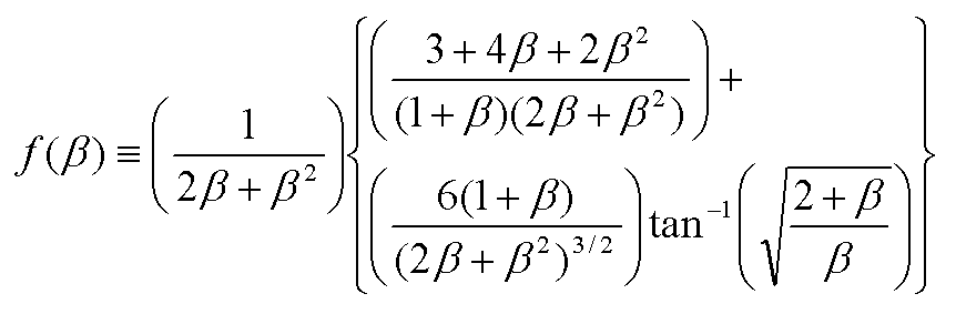
수학식 1에서 β는 t/(2r)이며, t는 힌지 두께이고, r은 힌지 반지름이며, f는 아래의 수학식 2에 의해 계산된 값이다.In Equation 1, β is t / (2r), t is hinge thickness, r is hinge radius, and f is a value calculated by Equation 2 below.
그리고 아래 수학식 3을 통해 굽힘 모멘트(![]()
![]()
![]()
![]()
수학식 3에서 ki는 해당 힌지의 강성계수이다.In Equation 3, k i is the stiffness coefficient of the hinge.
그리고 아래 수학식 4를 통해 손목에 걸리는 힘(![]()
![]()
![]()
![]()
수학식 4에서 Jx는 3자유도 병렬형 손목 메커니즘의 기구학적 자코비안이고, Jq는 3자유도 병렬형 손목 메커니즘의 구동 자코비안이다.In Equation 4, Jx is the kinematic Jacobian of the three degree of freedom parallel wrist mechanism, and Jq is the driving Jacobian of the three degree of freedom parallel wrist mechanism.
이와 같이 순응모듈(200)에 인가되는 굽힘 스트레인을 측정하여 손목에 걸리는 힘을 계산할 수 있어 환자의 상태에 따라 외골격장치(100)의 작동 제어가 용이하다는 장점이 있다.As described above, the bending force applied to the
아래에서는 이와 같이 구성된 외골격장치의 작동관계에 대해 설명한다.The following describes the operation relationship of the exoskeleton configured as described above.
환자의 팔을 외골격장치(100)에 안착시키면, 위팔(1H)은 고정 프레임(110)에 안착되고 아래팔(1L)은 회전 프레임(120)에 안착된다. 이때 위팔(1H)은 양측 제2링크(172)의 사이에 위치하고 아래팔(1L)의 측부에는 제5링크(175)가 아래팔(1L)의 길이방향으로 위치하며 제8링크(178)는 아래팔(1L)의 아래에 위치한다.When the patient's arm is seated on the
이 상태에서 제1구동모터(151)를 작동시키면, 도 4a 내지 도 4c에 도시된 바와 같이 제1링크(171)가 제1구동모터(151)의 회전축(151S)에 의해 회전하고, 연동하는 제2링크(172)는 제1힌지 브래킷(141)을 회전시키면서 제1힌지 브래킷(141)에 고정된 회전 프레임(120)이 힌지부(140)의 힌지 축(143)을 중심으로 상하방향(Y축)으로 회전한다.When the
아래에서는 외골격장치(100)에 팔을 안착하고 손잡이(131)를 손으로 파지한 상태에서 제3구동모터(153)를 작동시키면, 도 5a 내지 도 5c에 도시된 바와 같이 제3구동모터(153)에 의해 제6링크(176)가 회전하고, 연동하는 제7링크(177)가 이동하면서 제2가이드 바(182)가 전후방향으로 이동한다. 이때 유니버설조인트(192)로 연결된 제8링크(178)는 받침 프레임(130)의 상하 이동(Y축 방향)에 의해 기울기가 변하게 된다. 그리고 받침 프레임(130)에 연결된 제5링크(175) 또한 받침 프레임(130)의 상하 이동에 의해 기울기만 변할 뿐, 제5링크(175)와 연결된 제1가이드 바(181)는 전후방향으로 이동하지 않는다.In the following, when the arm is seated on the
한편, 제2구동모터(152)를 작동시키면, 도 6a 내지 도 6c에 도시된 바와 같이 제3링크(173)가 회전하고, 연동하는 제4링크(174)가 이동하면서 제1가이드 바(181)가 전후방향으로 이동한다. 이때 유니버설조인트(191)로 연결된 제5링크(175)는 받침 프레임(130)의 좌우 이동(X축 방향)에 의해 기울기가 변하게 된다. 그리고 받침 프레임(130)에 연결된 제8링크(178) 또한 받침 프레임(130)의 좌우 이동에 의해 기울기만 변할 뿐, 제8링크(178)와 연결된 제2가이드 바(182)는 전후방향으로 이동하지 않는다.Meanwhile, when the
한편, 제4구동모터(154)를 작동시키면, 도 7a 내지 도 7c에 도시된 바와 같이 제9링크(179)가 회전하고, 연동하는 제10링크(180)가 이동하면서, 받침 프레임(130)이 아래팔(1L)의 축(roll 축)을 중심으로 회전한다. 이때 제5링크(175) 및 제8링크(178)는 받침 프레임(130)의 회전에 의해 기울기가 변할 뿐, 제5링크(175)에 연결된 제1가이드 바(181)와 제8링크(178)에 연결된 제2가이드 바(182)는 전후방향으로 이동하지 않는다.Meanwhile, when the
앞서 설명한 바와 같이, 제1구동모터(151)는 팔꿈치와 대응하는 힌지부(140)를 중심으로 회전 프레임(120)을 회전시켜 아래팔(1L)을 상하방향으로 움직이게 하고, 제2구동모터(152)는 받침 프레임(130)을 좌우방향으로 이동시켜 손목을 좌우방향으로 움직이게 하며, 제3구동모터(153)는 받침 프레임(130)을 상하방향으로 이동시켜 손목을 좌우방향으로 움직이게 하며, 제4구동모터(154)는 받침 프레임(130)을 롤 축을 중심으로 회전시키면서 손(1F)과 아래팔(1L)을 비틀수 있게 한다.As described above, the
이와 같이 구성된 외골격장치(100)에 있어서, 제1구동모터(151)는 고정 프레임(110)의 저면에 길이방향으로 위치하고, 제2구동모터(152) 내지 제4구동모터(154)는 회전 프레임(120)의 저면에 길이방향으로 위치함으로써, 4개의 구동모터(151, 152, 153, 154)가 팔의 길이방향으로 위치한다. 따라서 외골격장치(100)의 폭을 좁힐 수 있어 환자와의 간섭을 피할 수 있다.In the
또한, 각 구동모터(151, 152, 153, 154)의 회전축(151S, 152S, 153S, 154S)에는 순응모듈(200)이 각각 장착되어 과도한 힘을 완충할 수 있고 순응모듈(200)에 장착된 스트레인 게이지(203)를 통해 전달되는 힘을 측정할 수 있다.In addition, the
앞서 설명한 본 발명에 따른 외골격장치(100)는 팔에 장착되는 것으로 설명하고 있으나, 손잡이(131)를 개량하면 다리근력보조를 위한 외골격장치로 사용할 수 있다. 구체적으로 손잡이를 대신하여 고정수단인 벨크로테이프, 밴드 및 후크 등을 장착하여 받침 프레임(130)에 올려진 발을 벨크로테이프, 밴드 및 후크 등으로 고정한다. 이때 고정 프레임(110)은 허벅지(대퇴뼈) 전방에 대응하고 회전 프레임(120)은 정강뼈의 전방에 대응하도록 위치한다. 이와 같이 구성된 외골격장치(100)는 무릎을 중심으로 정강뼈의 회전은 제1구동모터(151)에 의해 이루어지며, 발목을 중심으로 3자유도 회전하는 발은 제2구동모터(152) 내지 제4구동모터(154)에 의해 이루어진다.The
또한, 앞서 설명한 본 발명에 따른 외골격장치(100)는 고정 프레임(110), 회전 프레임(120) 및 받침 프레임(130)으로 구성된 것으로 설명하였으나, 경우에 따라서는 고정 프레임(110)과 회전 프레임(120)을 힌지부(140)로 연결하며 제1구동모터(151)로 회전 프레임(120)이 상하방향으로 회전하는 외골격장치를 구성하거나, 회전 프레임(120)과 받침 프레임(130)을 링크(173~180)들로 연결하고 받침 프레임(130)이 3자유도 운동하도록 제2구동모터(152) 내지 제4구동모터(154)로 구동시키는 외골격장치를 구성할 수 있다.In addition, the
또한, 앞서 설명한 본 발명에 따른 외골격장치(100)에 있어서, 제1베벨기어(161), 제2베벨기어(162) 및 제3베벨기어(163)는 경사축간 회전동력전달부로서, 베벨기어를 대신하여 다른 종류의 기어로 대체 가능하며, 또한 제5링크(175) 및 제8링크(178)의 양단에 장착된 유니버설 조인트(191, 192, 193)은 2자유도 이상의 회전조인트인 볼조인트 등으로 대체 가능하다.
In addition, in the
1H : 위팔
1L : 아래팔
1F : 손
100 : 외골격장치
110 : 고정 프레임
120 : 회전 프레임
130 : 받침 프레임
140 : 힌지부
151 ~ 154 : 구동모터
151S ~ 154S : 회전축
161, 162, 163 : 베벨기어
171 ~ 180 : 링크
181, 182 : 가이드 바
191, 192, 193 : 유니버설 조인트
179S, 180S : 힌지 축
193S : 유니버설 조인트 블록의 축1H: upper arm
1L: Lower arm
1F: Hand
100: exoskeleton
110: fixed frame
120: rotating frame
130: support frame
140: hinge part
151 ~ 154: drive motor
151S ~ 154S: Rotating Shaft
161, 162, 163: Bevel Gears
171-180: link
181, 182: guide bar
191, 192, 193: Universal Joint
179S, 180S: Hinge Shaft
193S: Axis of the universal joint block
Claims (21)
사지의 하부 골격과 대응하여 위치하며 고정 프레임에 힌지부로 결합되어 상하방향으로 회전하는 회전 프레임과,
고정 프레임에 장착되며 회전 프레임에 연결되어 회전 프레임이 상하방향으로 회전하도록 구동하는 제1모터와,
제1모터와 회전 프레임을 연결하는 링크들을 포함하며,
제1모터의 회전축에는 제1경사축간 회전동력전달부의 구동기어가 장착되며, 구동기어와 연동하는 연동기어의 축에는 제1링크가 고정되고, 제1링크의 단부에는 제2링크의 단부가 힌지 결합되며 제2링크의 단부는 힌지부에 고정된 것을 특징으로 하는 근력보조를 위한 외골격장치.
A fixed frame positioned corresponding to the upper skeleton of the extremities,
A rotating frame which is located in correspondence with the lower skeleton of the limb and is coupled to the fixed frame by a hinge and rotates in an up and down direction;
A first motor mounted to the fixed frame and connected to the rotating frame to drive the rotating frame to rotate in a vertical direction;
Links connecting the first motor and the rotating frame,
The first gear is fixed to the axis of the interlocking gear interlocked with the drive gear, and the end of the second link is hinged to the end of the first link. The exoskeleton for muscle strength support, characterized in that coupled to the end of the second link is fixed to the hinge portion.
사지의 하부 골격과 대응하여 위치하며 고정 프레임에 힌지부로 결합되어 상하방향으로 회전하는 회전 프레임과,
고정 프레임에 장착되며 회전 프레임에 연결되어 회전 프레임이 상하방향으로 회전하도록 구동하는 제1모터와,
제1모터와 회전 프레임을 연결하는 링크들을 포함하며,
힌지부는 고정 프레임에 형성된 제1힌지 브래킷과, 회전 프레임과 연결되어 제1힌지 브래킷과 대응하며 힌지 축으로 상대 회전 가능하게 장착된 제2힌지 브래킷을 포함하며, 제2링크는 제2힌지 브래킷에 힌지 결합된 것을 특징으로 하는 근력보조를 위한 외골격장치.
A fixed frame positioned corresponding to the upper skeleton of the extremities,
A rotating frame which is located in correspondence with the lower skeleton of the limb and is coupled to the fixed frame by a hinge and rotates in an up and down direction;
A first motor mounted to the fixed frame and connected to the rotating frame to drive the rotating frame to rotate in a vertical direction;
Links connecting the first motor and the rotating frame,
The hinge portion includes a first hinge bracket formed on the fixed frame and a second hinge bracket connected to the rotating frame to correspond to the first hinge bracket and rotatably mounted to the hinge axis, and the second link is connected to the second hinge bracket. An exoskeleton for muscle strength support, characterized in that the hinge.
제2힌지 브래킷에는 슬라이드 브래킷이 형성되고, 슬라이드 브래킷에는 회전 프레임의 길이방향으로 장공이 형성되며, 회전 프레임에 형성된 슬라이더가 장공에 끼워져 잠금되거나 잠금해제된 상태로 장공의 길이방향으로 이동 가능한 것을 특징으로 하는 근력보조를 위한 외골격장치.
5. The method of claim 4,
The second hinge bracket is formed with a slide bracket, the slide bracket is formed with a long hole in the longitudinal direction of the rotating frame, the slider formed on the rotating frame is inserted into the long hole is movable in the longitudinal direction of the long hole in the locked or unlocked state Exoskeleton for muscle strength.
사지의 말단부를 받쳐주는 받침 프레임과,
회전 프레임에 장착되며 받침 프레임에 연결되어 받침 프레임이 상하방향과 좌우방향으로의 회전 및 하부 골격의 축(롤축)을 기준으로 회전하도록 구동하는 모터들과,
모터들과 받침 프레임을 연결하는 링크들을 포함하는 것을 특징으로 하는 근력보조를 위한 외골격장치.
A rotating frame positioned corresponding to the lower skeleton of the limbs,
Support frame supporting the distal end of the limbs,
Motors mounted on the rotation frame and connected to the support frame to drive the support frame to rotate in the up and down directions and to the left and right directions and to rotate about the axis of the lower frame (roll axis);
An exoskeleton for muscle supplement, characterized in that it comprises a link connecting the motor and the support frame.
상기 모터들은 받침 프레임이 좌우방향으로 회전하도록 구동하는 제2모터와, 받침 프레임이 상하방향으로 회전하도록 구동하는 제3모터와, 받침 프레임이 롤축을 중심으로 회전하도록 구동하는 제4모터를 포함하며,
제2모터, 제3모터 및 제4모터의 각 회전축은 받침 프레임의 길이방향으로 위치하는 것을 특징으로 하는 근력보조를 위한 외골격장치.
The method according to claim 6,
The motors include a second motor for driving the support frame to rotate in the left and right directions, a third motor for driving the support frame to rotate in the vertical direction, and a fourth motor to drive the support frame to rotate about the roll axis. ,
Each rotation axis of the second motor, the third motor and the fourth motor is an exoskeleton for muscle strength support, characterized in that located in the longitudinal direction of the support frame.
제2모터의 회전축에는 제2경사축간 회전동력전달부의 구동기어가 장착되고, 구동기어와 연동하는 연동기어의 축에는 제3링크가 고정되며, 제3링크의 단부에는 제4링크의 일단부가 힌지 결합되고, 제5링크의 양단에는 회전조인트가 장착되며,
제4링크의 타단부는 제5링크의 한 쪽 회전조인트의 블록에 힌지 결합되며, 받침 프레임에는 제5링크의 다른 쪽 회전조인트의 블록이 고정된 것을 특징으로 하는 근력보조를 위한 외골격장치.
The method according to claim 6,
The drive shaft of the rotational power transmission unit between the second inclination shaft is mounted on the rotation shaft of the second motor, the third link is fixed to the shaft of the interlocking gear interlocking with the drive gear, and one end of the fourth link is hinged at the end of the third link. Coupled, and both ends of the fifth link are equipped with a rotary joint,
The other end of the fourth link is hinged to the block of one rotation joint of the fifth link, the exoskeleton for muscle strength support, characterized in that the block of the other rotation joint of the fifth link is fixed to the support frame.
제4링크의 타단부가 힌지 결합된 회전조인트의 블록에는 회전 프레임의 길이방향으로 제1가이드 바가 고정되고, 제1가이드 바는 회전 프레임에 고정된 제1홀더에 끼워져 직선 운동하는 것을 특징으로 하는 근력보조를 위한 외골격장치.
9. The method of claim 8,
The first guide bar is fixed to the block of the rotary joint hinged to the other end of the fourth link in the longitudinal direction of the rotating frame, the first guide bar is fitted into the first holder fixed to the rotating frame to move linearly Exoskeletal device for strength support.
제3모터의 회전축에는 제3경사축간 회전동력전달부의 구동기어가 장착되고, 구동기어와 연동하는 연동기어의 축에는 제6링크가 고정되며, 제6링크의 단부에는 제7링크의 일단부가 힌지 결합되고, 제8링크의 양단에는 회전조인트가 장착되며,
제7링크의 타단부는 제8링크의 한 쪽 회전조인트의 블록에 힌지 결합되며, 받침 프레임에는 제8링크의 다른 쪽 회전조인트의 블록이 고정된 것을 특징으로 하는 근력보조를 위한 외골격장치.
The method of claim 7, wherein
The drive shaft of the rotational power transmission unit between the third inclination shafts is mounted to the rotation shaft of the third motor, and the sixth link is fixed to the shaft of the interlocking gear interlocking with the drive gear, and one end of the seventh link is hinged to the end of the sixth link. Coupled, and both ends of the eighth link are equipped with a rotary joint,
The other end of the seventh link is hinged to the block of one rotation joint of the eighth link, the exoskeleton for muscle strength support, characterized in that the block of the other rotation joint of the eighth link is fixed to the support frame.
제7링크의 타단부가 힌지 결합된 회전조인트의 블록에는 회전 프레임의 길이방향으로 제2가이드 바가 고정되고, 제2가이드 바는 회전 프레임에 고정된 제2홀더에 끼워져 직선 운동하는 것을 특징으로 하는 근력보조를 위한 외골격장치.
The method of claim 10,
The second guide bar is fixed to the block of the rotary joint hinged to the other end of the seventh link in the longitudinal direction of the rotating frame, the second guide bar is fitted into the second holder fixed to the rotating frame to move linearly Exoskeletal device for strength support.
제4모터의 단부에는 회전조인트가 장착되며, 회전조인트의 블록에 제9링크의 일단부가 고정되고, 제9링크의 타단부에는 제10링크의 일단부가 힌지 결합되며, 제10링크의 타단부는 받침 프레임에 힌지 결합된 것을 특징으로 하는 근력보조를 위한 외골격장치.
The method of claim 7, wherein
A rotary joint is mounted at the end of the fourth motor, one end of the ninth link is fixed to the block of the rotary joint, one end of the tenth link is hinged to the other end of the ninth link, and the other end of the tenth link is Exoskeleton for muscle strength support, characterized in that the hinge is coupled to the support frame.
제9링크의 일단부는 회전조인트의 블록에 형성된 축에 고정되며 축의 연장선과, 제9링크와 제10링크를 연결하는 힌지 축의 연장선 및 제10링크와 받침 프레임을 연결하는 힌지 축의 연장선은 한 점에서 만나는 것을 특징으로 하는 근력보조를 위한 외골격장치.
The method of claim 12,
One end of the ninth link is fixed to the shaft formed in the block of the rotation joint, and the extension line of the shaft, the extension line of the hinge shaft connecting the ninth link and the tenth link, and the extension line of the hinge shaft connecting the tenth link and the support frame, are at one point. Exoskeleton for muscle strength, characterized in that meeting.
받침 프레임은 상기 한 점을 중심으로 만곡된 것을 특징으로 하는 근력보조를 위한 외골격장치.
The method of claim 13,
Support frame is an exoskeleton device for muscle strength, characterized in that the curved around the one point.
받침 프레임에는 손잡이가 장착되어 사지의 말단부인 손으로 손잡이를 파지하는 것을 특징으로 하는 근력보조를 위한 외골격장치.
The method according to claim 6,
The support frame is equipped with a handle is an exoskeleton device for muscle strength, characterized in that the hand grip the end of the limb.
받침 프레임에는 고정수단이 장착되어 발을 고정수단으로 고정시키는 것을 특징으로 하는 근력보조를 위한 외골격장치.
The method according to claim 6,
The support frame is equipped with a fixing means for exoskeleton for muscle strength, characterized in that to fix the foot to the fixing means.
제1모터의 회전축에는 순응모듈인 유연 힌지가 각각 장착된 것을 특징으로 하는 근력보조를 위한 외골격장치.
The method according to claim 3 or 4,
Rotating shaft of the first motor exoskeleton for muscle strength support, characterized in that each of the flexible hinge is fitted to the compliance module.
제2모터, 제3모터, 제4모터의 각 회전축에는 순응모듈인 유연 힌지가 각각 장착된 것을 특징으로 하는 근력보조를 위한 외골격장치.
The method of claim 7, wherein
The exoskeleton for muscle strength assistance, characterized in that the flexible hinge as a compliance module is mounted on each of the rotary shaft of the second motor, the third motor, the fourth motor.
상기 유연 힌지에는 스트레인 게이지가 장착되어 유연 힌지에 가해지는 응력을 측정하는 것을 특징으로 하는 근력보조를 위한 외골격장치.
18. The method of claim 17,
The flexible hinge is equipped with a strain gauge exoskeleton for muscle strength support, characterized in that for measuring the stress applied to the flexible hinge.
상기 유연 힌지에는 스트레인 게이지가 장착되어 유연 힌지에 가해지는 응력을 측정하는 것을 특징으로 하는 근력보조를 위한 외골격장치.
19. The method of claim 18,
The flexible hinge is equipped with a strain gauge exoskeleton for muscle strength support, characterized in that for measuring the stress applied to the flexible hinge.
사지의 하부 골격과 대응하여 위치하며 고정 프레임에 힌지부로 결합되어 상하방향으로 회전하는 회전 프레임과,
사지의 말단부를 받쳐주는 받침 프레임과,
고정 프레임에 장착되며 회전 프레임에 연결되어 회전 프레임이 상하방향으로 회전하도록 구동하는 제1모터와,
회전 프레임에 장착되며 받침 프레임에 연결되어 받침 프레임이 상하방향과 좌우방향으로의 회전 및 하부 골격의 축(롤축)을 기준으로 회전하도록 구동하는 모터들과,
제1모터와 회전 프레임을 연결하는 링크들과,
모터들과 받침 프레임을 연결하는 링크들을 포함하는 것을 특징으로 하는 근력보조를 위한 외골격장치.A fixed frame positioned corresponding to the upper skeleton of the extremities,
A rotating frame which is located in correspondence with the lower skeleton of the limb and is coupled to the fixed frame by a hinge and rotates in an up and down direction;
Support frame supporting the distal end of the limbs,
A first motor mounted to the fixed frame and connected to the rotating frame to drive the rotating frame to rotate in a vertical direction;
Motors mounted on the rotation frame and connected to the support frame to drive the support frame to rotate in the up and down directions and to the left and right directions and to rotate about the axis of the lower frame (roll axis);
Links connecting the first motor and the rotating frame,
An exoskeleton for muscle supplement, characterized in that it comprises a link connecting the motor and the support frame.
Priority Applications (2)
| Application Number | Priority Date | Filing Date | Title |
|---|---|---|---|
| KR1020110101430A KR101295004B1 (en) | 2011-10-05 | 2011-10-05 | Exoskeleton mechanism for limb power assistance |
| US13/617,985 US9592174B2 (en) | 2011-10-05 | 2012-09-14 | Exoskeleton mechanism for joint movement assistance |
Applications Claiming Priority (1)
| Application Number | Priority Date | Filing Date | Title |
|---|---|---|---|
| KR1020110101430A KR101295004B1 (en) | 2011-10-05 | 2011-10-05 | Exoskeleton mechanism for limb power assistance |
Publications (2)
| Publication Number | Publication Date |
|---|---|
| KR20130037084A KR20130037084A (en) | 2013-04-15 |
| KR101295004B1 true KR101295004B1 (en) | 2013-08-08 |
Family
ID=48042517
Family Applications (1)
| Application Number | Title | Priority Date | Filing Date |
|---|---|---|---|
| KR1020110101430A KR101295004B1 (en) | 2011-10-05 | 2011-10-05 | Exoskeleton mechanism for limb power assistance |
Country Status (2)
| Country | Link |
|---|---|
| US (1) | US9592174B2 (en) |
| KR (1) | KR101295004B1 (en) |
Cited By (9)
| Publication number | Priority date | Publication date | Assignee | Title |
|---|---|---|---|---|
| CN104606027A (en) * | 2015-02-02 | 2015-05-13 | 浙江大学台州研究院 | Elbow joint exercise rehabilitation device |
| KR101716761B1 (en) | 2015-09-11 | 2017-03-15 | 국방과학연구소 | Wearable MDOF joint for assisting muscular strength that coincides with the center of rotation |
| WO2021096131A1 (en) * | 2019-11-15 | 2021-05-20 | 에이치로보틱스 주식회사 | Rehabilitation exercise device for upper and lower limbs |
| WO2021096127A1 (en) * | 2019-11-15 | 2021-05-20 | 에이치로보틱스 주식회사 | Rehabilitation exercise device for upper and lower limbs |
| KR20210078920A (en) | 2019-12-19 | 2021-06-29 | 건국대학교 산학협력단 | Articulation assistance apparatus of clothing type using the shape memory alloy wire |
| KR20210108285A (en) * | 2020-02-25 | 2021-09-02 | 에이치로보틱스 주식회사 | Rehabilitation exercise apparatus for upper limb and lower limb |
| KR20210108850A (en) * | 2020-02-25 | 2021-09-03 | 에이치로보틱스 주식회사 | Rehabilitation exercise apparatus for upper limb and lower limb |
| KR20210108851A (en) * | 2020-02-25 | 2021-09-03 | 에이치로보틱스 주식회사 | Rehabilitation exercise apparatus for upper limb and lower limb |
| KR20210108849A (en) * | 2020-02-25 | 2021-09-03 | 에이치로보틱스 주식회사 | Rehabilitation exercise apparatus for upper limb and lower limb |
Families Citing this family (55)
| Publication number | Priority date | Publication date | Assignee | Title |
|---|---|---|---|---|
| US9789603B2 (en) | 2011-04-29 | 2017-10-17 | Sarcos Lc | Teleoperated robotic system |
| US20130145530A1 (en) * | 2011-12-09 | 2013-06-13 | Manu Mitra | Iron man suit |
| US9616580B2 (en) | 2012-05-14 | 2017-04-11 | Sarcos Lc | End effector for a robotic arm |
| KR20140002840A (en) * | 2012-06-26 | 2014-01-09 | 한국과학기술연구원 | Likage mechnism for physical multi-contact interaction |
| WO2015099858A2 (en) | 2013-09-30 | 2015-07-02 | Board Of Regents, The University Of Texas System | Upper-body robotic exoskeleton |
| US10441452B1 (en) * | 2014-02-28 | 2019-10-15 | Waleed Al-Oboudi | Shoulder rotation device |
| US20150272807A1 (en) * | 2014-03-27 | 2015-10-01 | Board Of Trustees Of Northern Illinois University | Exoskeleton for essential tremor and parkinson's disease |
| US10766133B2 (en) | 2014-05-06 | 2020-09-08 | Sarcos Lc | Legged robotic device utilizing modifiable linkage mechanism |
| US10512583B2 (en) * | 2014-05-06 | 2019-12-24 | Sarcos Lc | Forward or rearward oriented exoskeleton |
| US10123929B2 (en) * | 2014-06-17 | 2018-11-13 | Colorado School Of Mines | Wrist and forearm exoskeleton |
| JP6087329B2 (en) * | 2014-09-19 | 2017-03-01 | Thk株式会社 | Rotation drive mechanism in robot |
| DE102015101329A1 (en) * | 2015-01-29 | 2016-08-04 | Airbus Operations Gmbh | Support device for stabilizing a body part of a person |
| JP6301862B2 (en) * | 2015-03-04 | 2018-03-28 | 上銀科技股▲分▼有限公司 | Lower leg exercise device and control method thereof |
| CN105476739B (en) * | 2016-02-15 | 2018-06-29 | 鲁俊东 | Orthopedic fixer outside a kind of elbow joint |
| EP3429427A4 (en) * | 2016-03-18 | 2019-12-25 | Ekso Bionics, Inc. | Device and method for strengthening the arms of huaman exoskeletons |
| CN106002922B (en) * | 2016-07-14 | 2018-08-14 | 安徽艾塔智能科技有限公司 | A kind of building site carrying intelligent robot movable pulley |
| CN106115199B (en) * | 2016-07-14 | 2018-06-01 | 湖南工学院 | Intelligent robot is carried in a kind of construction based on hybrid connected structure |
| CN106420261B (en) * | 2016-10-20 | 2020-07-14 | 上海交通大学 | Semi-exoskeleton upper limb rehabilitation instrument |
| US10828767B2 (en) | 2016-11-11 | 2020-11-10 | Sarcos Corp. | Tunable actuator joint modules having energy recovering quasi-passive elastic actuators with internal valve arrangements |
| US10821614B2 (en) | 2016-11-11 | 2020-11-03 | Sarcos Corp. | Clutched joint modules having a quasi-passive elastic actuator for a robotic assembly |
| US10765537B2 (en) | 2016-11-11 | 2020-09-08 | Sarcos Corp. | Tunable actuator joint modules having energy recovering quasi-passive elastic actuators for use within a robotic system |
| US10919161B2 (en) | 2016-11-11 | 2021-02-16 | Sarcos Corp. | Clutched joint modules for a robotic system |
| KR20180076139A (en) * | 2016-12-27 | 2018-07-05 | 삼성전자주식회사 | A motion assist apparatus |
| JP6457560B2 (en) * | 2017-01-06 | 2019-01-23 | ファナック株式会社 | Rotating shaft joint structure |
| CN106955218A (en) * | 2017-03-23 | 2017-07-18 | 林娟娟 | Arm rehabilitation training instrument |
| KR101967215B1 (en) | 2017-11-03 | 2019-04-09 | 한국기계연구원 | Cloth for enhancing muscular strenght and method of controlling the same |
| US10843330B2 (en) | 2017-12-07 | 2020-11-24 | Sarcos Corp. | Resistance-based joint constraint for a master robotic system |
| US11331809B2 (en) | 2017-12-18 | 2022-05-17 | Sarcos Corp. | Dynamically controlled robotic stiffening element |
| CN110314065A (en) * | 2018-03-29 | 2019-10-11 | 京东方科技集团股份有限公司 | Exoskeleton rehabilitation power assisting device |
| KR102077050B1 (en) | 2018-07-09 | 2020-02-13 | 한국기계연구원 | Artificial muscle assembly, muscle strength-enhancing garment having the same, and control method of artificial muscle assembly |
| CN108972605B (en) * | 2018-09-10 | 2024-04-16 | 河南翔宇医疗设备股份有限公司 | Bionic hand simulating hand movement |
| CN109500802B (en) * | 2018-12-12 | 2023-09-01 | 昆明理工大学 | Multi-degree-of-freedom bionic mechanical arm |
| US11241801B2 (en) | 2018-12-31 | 2022-02-08 | Sarcos Corp. | Robotic end effector with dorsally supported actuation mechanism |
| US10906191B2 (en) | 2018-12-31 | 2021-02-02 | Sarcos Corp. | Hybrid robotic end effector |
| US11351675B2 (en) | 2018-12-31 | 2022-06-07 | Sarcos Corp. | Robotic end-effector having dynamic stiffening elements for conforming object interaction |
| US11123608B2 (en) * | 2019-03-05 | 2021-09-21 | Hiwin Technologies Corp. | Upper limb training system and control method thereof |
| KR102034988B1 (en) * | 2019-05-15 | 2019-10-21 | 김일열 | Transport aid device for reducing arm joint overload |
| CN110076758B (en) * | 2019-05-23 | 2022-07-12 | 上海大学 | Human-simulated lower limb exoskeleton configuration method based on parallel-serial mechanism |
| CN112091942A (en) * | 2019-10-16 | 2020-12-18 | 卢定华 | Exoskeleton type auxiliary boosting mechanical arm |
| US11883956B2 (en) * | 2020-03-27 | 2024-01-30 | Agency For Defense Development | Wearable gravity compensation apparatus capable of multiple degrees of freedom of movement |
| US11298287B2 (en) | 2020-06-02 | 2022-04-12 | Dephy, Inc. | Systems and methods for a compressed controller for an active exoskeleton |
| US11147733B1 (en) | 2020-06-04 | 2021-10-19 | Dephy, Inc. | Systems and methods for bilateral wireless communication |
| US11148279B1 (en) * | 2020-06-04 | 2021-10-19 | Dephy, Inc. | Customized configuration for an exoskeleton controller |
| US11389367B2 (en) | 2020-06-05 | 2022-07-19 | Dephy, Inc. | Real-time feedback-based optimization of an exoskeleton |
| US11173093B1 (en) | 2020-09-16 | 2021-11-16 | Dephy, Inc. | Systems and methods for an active exoskeleton with local battery |
| KR20220053349A (en) | 2020-10-22 | 2022-04-29 | 주식회사 에프알티 | Wearable exoskeletal appraratus to assist with muscular strength |
| US11833676B2 (en) | 2020-12-07 | 2023-12-05 | Sarcos Corp. | Combining sensor output data to prevent unsafe operation of an exoskeleton |
| US11794345B2 (en) | 2020-12-31 | 2023-10-24 | Sarcos Corp. | Unified robotic vehicle systems and methods of control |
| USD1011398S1 (en) | 2021-08-13 | 2024-01-16 | Festool Gmbh | Wearable robotic exoskeleton |
| US11541530B1 (en) * | 2021-09-30 | 2023-01-03 | Harmonic Bionics, Inc. | Compliant mechanism for improving axial load sensing in robotic actuators |
| CN114917109B (en) * | 2022-05-19 | 2024-04-12 | 哈尔滨理工大学 | Wrist rehabilitation exoskeleton robot |
| US11826907B1 (en) | 2022-08-17 | 2023-11-28 | Sarcos Corp. | Robotic joint system with length adapter |
| US11717956B1 (en) | 2022-08-29 | 2023-08-08 | Sarcos Corp. | Robotic joint system with integrated safety |
| US11924023B1 (en) | 2022-11-17 | 2024-03-05 | Sarcos Corp. | Systems and methods for redundant network communication in a robot |
| US11897132B1 (en) | 2022-11-17 | 2024-02-13 | Sarcos Corp. | Systems and methods for redundant network communication in a robot |
Citations (4)
| Publication number | Priority date | Publication date | Assignee | Title |
|---|---|---|---|---|
| JP2007029113A (en) * | 2005-07-22 | 2007-02-08 | Toyota Motor Corp | Assist apparatus |
| KR100815477B1 (en) | 2006-10-17 | 2008-03-20 | 강원대학교산학협력단 | Apparatus for physical therapy for patient with limbs rigidify |
| KR20110066565A (en) * | 2009-12-11 | 2011-06-17 | 대한민국(국립재활원장) | Rehabilitative and assistive device for elbow movements |
| KR101065420B1 (en) * | 2008-12-16 | 2011-09-16 | 한양대학교 산학협력단 | Wearable Robotic System for the Rehabilitation Training of upper limbs |
Family Cites Families (9)
| Publication number | Priority date | Publication date | Assignee | Title |
|---|---|---|---|---|
| US4521924A (en) * | 1983-03-01 | 1985-06-11 | University Of Utah | Electrically driven artificial arm |
| CA2023505A1 (en) * | 1990-08-17 | 1992-02-18 | John Saringer | Continuous passive motion device |
| US6676707B2 (en) * | 2001-05-24 | 2004-01-13 | Tachung C. Yih | Prosthetic devices for upper and lower limbs |
| US7618381B2 (en) * | 2004-10-27 | 2009-11-17 | Massachusetts Institute Of Technology | Wrist and upper extremity motion |
| US20080009771A1 (en) * | 2006-03-29 | 2008-01-10 | Joel Perry | Exoskeleton |
| WO2008028190A2 (en) * | 2006-09-01 | 2008-03-06 | Worcester Polytechnic Institute | Two degree of freedom powered orthosis |
| FR2917323B1 (en) * | 2007-06-12 | 2009-10-02 | Commissariat Energie Atomique | FRONT ROTATION MECHANISM AND ORTHESIS COMPRISING SUCH A MECHANISM |
| US8274244B2 (en) * | 2008-08-14 | 2012-09-25 | Tibion Corporation | Actuator system and method for extending a joint |
| JP5243159B2 (en) * | 2008-09-12 | 2013-07-24 | パナソニック株式会社 | Wrist assist device |
-
2011
- 2011-10-05 KR KR1020110101430A patent/KR101295004B1/en active IP Right Grant
-
2012
- 2012-09-14 US US13/617,985 patent/US9592174B2/en active Active
Patent Citations (4)
| Publication number | Priority date | Publication date | Assignee | Title |
|---|---|---|---|---|
| JP2007029113A (en) * | 2005-07-22 | 2007-02-08 | Toyota Motor Corp | Assist apparatus |
| KR100815477B1 (en) | 2006-10-17 | 2008-03-20 | 강원대학교산학협력단 | Apparatus for physical therapy for patient with limbs rigidify |
| KR101065420B1 (en) * | 2008-12-16 | 2011-09-16 | 한양대학교 산학협력단 | Wearable Robotic System for the Rehabilitation Training of upper limbs |
| KR20110066565A (en) * | 2009-12-11 | 2011-06-17 | 대한민국(국립재활원장) | Rehabilitative and assistive device for elbow movements |
Cited By (14)
| Publication number | Priority date | Publication date | Assignee | Title |
|---|---|---|---|---|
| CN104606027A (en) * | 2015-02-02 | 2015-05-13 | 浙江大学台州研究院 | Elbow joint exercise rehabilitation device |
| KR101716761B1 (en) | 2015-09-11 | 2017-03-15 | 국방과학연구소 | Wearable MDOF joint for assisting muscular strength that coincides with the center of rotation |
| WO2021096131A1 (en) * | 2019-11-15 | 2021-05-20 | 에이치로보틱스 주식회사 | Rehabilitation exercise device for upper and lower limbs |
| WO2021096127A1 (en) * | 2019-11-15 | 2021-05-20 | 에이치로보틱스 주식회사 | Rehabilitation exercise device for upper and lower limbs |
| KR20210078920A (en) | 2019-12-19 | 2021-06-29 | 건국대학교 산학협력단 | Articulation assistance apparatus of clothing type using the shape memory alloy wire |
| KR102434946B1 (en) | 2019-12-19 | 2022-08-22 | 건국대학교 산학협력단 | Articulation assistance apparatus of clothing type using the shape memory alloy wire |
| KR20210108850A (en) * | 2020-02-25 | 2021-09-03 | 에이치로보틱스 주식회사 | Rehabilitation exercise apparatus for upper limb and lower limb |
| KR20210108851A (en) * | 2020-02-25 | 2021-09-03 | 에이치로보틱스 주식회사 | Rehabilitation exercise apparatus for upper limb and lower limb |
| KR20210108849A (en) * | 2020-02-25 | 2021-09-03 | 에이치로보틱스 주식회사 | Rehabilitation exercise apparatus for upper limb and lower limb |
| KR102352602B1 (en) | 2020-02-25 | 2022-01-19 | 에이치로보틱스 주식회사 | Rehabilitation exercise apparatus for upper limb and lower limb |
| KR102352603B1 (en) | 2020-02-25 | 2022-01-20 | 에이치로보틱스 주식회사 | Rehabilitation exercise apparatus for upper limb and lower limb |
| KR102352604B1 (en) | 2020-02-25 | 2022-01-20 | 에이치로보틱스 주식회사 | Rehabilitation exercise apparatus for upper limb and lower limb |
| KR102387577B1 (en) * | 2020-02-25 | 2022-04-19 | 에이치로보틱스 주식회사 | Rehabilitation exercise apparatus for upper limb and lower limb |
| KR20210108285A (en) * | 2020-02-25 | 2021-09-02 | 에이치로보틱스 주식회사 | Rehabilitation exercise apparatus for upper limb and lower limb |
Also Published As
| Publication number | Publication date |
|---|---|
| KR20130037084A (en) | 2013-04-15 |
| US20130090580A1 (en) | 2013-04-11 |
| US9592174B2 (en) | 2017-03-14 |
Similar Documents
| Publication | Publication Date | Title |
|---|---|---|
| KR101295004B1 (en) | Exoskeleton mechanism for limb power assistance | |
| EP3156193B1 (en) | Worn movement assistance device | |
| US8800366B2 (en) | Robotic exoskeleton for limb movement | |
| JP4573798B2 (en) | Lumbar support device | |
| KR102158131B1 (en) | Walking assist apparatus | |
| US20060069336A1 (en) | Ankle interface | |
| CN108883023B (en) | Treatment device for performing an assisted movement of a finger of a patient's hand | |
| JP4811868B2 (en) | Upper limb finger function recovery training device | |
| US10383784B2 (en) | Gait training system and methods | |
| KR102120960B1 (en) | A supporting frame and a motion assistance apparatus comprising thereof | |
| KR101241800B1 (en) | Exoskeleton Apparatus For Assistant physical strength | |
| JP2015188758A (en) | Joint assembly and walking assistance robot including the same | |
| Cai et al. | Self-adjusting, isostatic exoskeleton for the human knee joint | |
| KR101901216B1 (en) | Modular upper limb exoskeleton robot | |
| JP6495128B2 (en) | Work assist device | |
| CN112025681B (en) | Electric waist assisting exoskeleton | |
| CN109124988B (en) | Guiding mechanism, lower limb rehabilitation exoskeleton and exoskeleton robot | |
| JP2017209765A (en) | Power assist device | |
| JP6232613B2 (en) | Walking training device for hemiplegic patients | |
| KR101390219B1 (en) | Exoskeleton | |
| CN216496401U (en) | Ankle joint rehabilitation robot | |
| Veneman et al. | Evaluation of the effect on walking of balance-related degrees of freedom in a robotic gait training device | |
| CN113813142A (en) | Ankle joint rehabilitation robot | |
| EP4117597A1 (en) | Leg actuation apparatus and gait rehabilitation apparatus | |
| JP2023518787A (en) | Self-aligning mechanisms in passive and powered exoskeletons |
Legal Events
| Date | Code | Title | Description |
|---|---|---|---|
| A201 | Request for examination | ||
| E902 | Notification of reason for refusal | ||
| E701 | Decision to grant or registration of patent right | ||
| GRNT | Written decision to grant | ||
| FPAY | Annual fee payment |
Payment date: 20160728 Year of fee payment: 4 |
|
| FPAY | Annual fee payment |
Payment date: 20190801 Year of fee payment: 7 |