JP6780977B2 - Cloth thrower - Google Patents
Cloth thrower Download PDFInfo
- Publication number
- JP6780977B2 JP6780977B2 JP2016147348A JP2016147348A JP6780977B2 JP 6780977 B2 JP6780977 B2 JP 6780977B2 JP 2016147348 A JP2016147348 A JP 2016147348A JP 2016147348 A JP2016147348 A JP 2016147348A JP 6780977 B2 JP6780977 B2 JP 6780977B2
- Authority
- JP
- Japan
- Prior art keywords
- cloth
- chuck
- claw
- projecting piece
- piece
- Prior art date
- Legal status (The legal status is an assumption and is not a legal conclusion. Google has not performed a legal analysis and makes no representation as to the accuracy of the status listed.)
- Active
Links
Images


Description
本発明は、布類投入機に関する。さらに詳しくは、洗濯済みのシーツや包布(2枚生地の布団カバーなど袋状のもの)、枕カバー、タオル類、テーブルクロス、衣類などの布類を洗濯し、アイロンがけする際は、その布類を四角形に展開し、プレスや折り畳み機などの次工程装置に供給するために布類展開装置が用いられる。そして、この布類展開装置などに、洗濯済みの布類を投入するのは布類投入機が用いられる。本発明は、このような布類投入機に関する。 The present invention relates to a cloth throwing machine. More specifically, when washing and ironing washed sheets and wrapping cloth (bag-shaped items such as two-piece cloth duvet cover), pillowcases, towels, tablecloths, clothing, etc. A cloth unfolding device is used to unfold the cloth into a square shape and supply it to a next process device such as a press or a folding machine. Then, a cloth loading machine is used to load the washed cloth into the cloth deploying device or the like. The present invention relates to such a cloth throwing machine.
ホテルや病院などでは大量にシーツが使用され、その使用済みのシーツはランドリー工場で洗濯、アイロンがけされ、再度ホテルや病院などで使用されることが一般的である。
ランドリー工場においては、シーツなどの四角形で比較的大きな寸法を有する布類を、洗濯したあとプレス機でプレスしたり、折り畳み機で折りたたんだりする作業が行なわれる。それらの処理装置に布類を供給するには、布類を予め四角形に展開させる必要がある。
布類を四角形に展開する作業を作業員が行う場合、作業に多大な時間と労力が必要であるため、近年では、この作業を自動で行う展開装置によって行われている。また、この展開装置に洗濯済みの布類をまず投入しなければならないが、その投入も機械化されて投入機が用いられるようになっている。
A large amount of sheets are used in hotels and hospitals, and the used sheets are generally washed and ironed in laundry factories and then used again in hotels and hospitals.
In a laundry factory, quadrangular cloths such as sheets having a relatively large size are washed and then pressed by a press or folded by a folding machine. In order to supply the cloth to those processing devices, it is necessary to expand the cloth into a quadrangle in advance.
When a worker performs the work of unfolding the cloth in a quadrangle, a large amount of time and labor is required for the work. Therefore, in recent years, the work is performed by an unfolding device that automatically performs this work. In addition, the washed cloth must be loaded into this deploying device first, but the loading is also mechanized and the loading machine is used.
特許文献1に記載された従来の展開装置および投入機の基本構成は、概略つぎのように構成されている。
図5において、80はシーツ等の布類投入機であり、展開装置の左右両端部に設けられている。布類投入機80におけるハンガー81に作業員がシーツYをつかませると、ハンガー81がいったん最上端まで上昇して少し奥側に移動し、再び少し下降した時点で、展開装置の横行チャック20R、20LにシーツYを受け渡す。ついで、布類の一辺を横行チャック20Rまたは20Lでつかんでベルトコンベヤ10上に引きづり込み、そのベルトコンベヤ10を前方に駆動して布類を装置前面に垂れ下がらせ、別の伸展チャック40R,40Lで布類の幅方向両端をつかんで引っ張って吊下げる。このように四角形に展開した状態で布類を装置内に引き込みかつ排出してプレス機等に送り込んでいる。
The basic configuration of the conventional deploying device and the throwing machine described in Patent Document 1 is roughly configured as follows.
In FIG. 5,
前記ハンガー81には、その両端にチャック82が取付けられている。この従来のチャック82を図6および図7に基づき説明する。
チャック82は、チャック本体83と爪片84を備えている。チャック本体83は横向きに凹んだ凹所を形成するように、下突片85と上突片86を備えている。上突片86には爪片84がピン87で回動自在に支持され、かつ爪片84の上部とチャック本体83との間にはバネ88が張設されている。
Chuck 82s are attached to both ends of the
The
下突片85と上突片86とは同じ幅と同じ長さを有している。図6に示すように、バネ88で爪片84を引っ張って立てているときは、爪片84の下端部が下突片85の表面に当るので、シーツ等をこの間に挟むことができる。
The
しかるに、上記従来例では、つぎのような問題があった。
図7に示すように、作業員がシーツをチャック82に引っ掛けるとき、斜め上方(約45°)からチャック82を見下すことになるが、この視線に直交する上突片86の先端と下突片85の先端との間の間隔wは狭いので、シーツを下から支える部材となる下突片85は上突片86によってよく見えないまま作業することとなる。この場合、シーツを下突片85の上面にうまく挿入できないという操作ミスも発生しやすい。この問題は、熟練すると回避しやすいが、それでも完璧ではなく、作業能率向上の阻害要因となっていた。
However, in the above-mentioned conventional example, there are the following problems.
As shown in FIG. 7, when the worker hooks the sheets on the
本発明は上記事情に鑑み、シーツ等の布類の把持ミスを大きく低減できる布類投入機を提供することを目的とする。また、本発明は、把持操作の高能率化を図れる布類投入機を提供することを目的とする。 In view of the above circumstances, an object of the present invention is to provide a cloth throwing machine capable of greatly reducing gripping errors of cloth such as sheets. Another object of the present invention is to provide a cloth throwing machine capable of improving the efficiency of gripping operation.
第1発明の布類投入機は、布類を把持し吊下げてから別装置に受渡すための投入機であって、布類の端縁を把持するチャックを備えており、該チャックは、布類の端縁を挿入する凹所の下面と上面に下突片と上突片が形成され、かつ該凹所内で爪が開閉する構造をもち、前記下突片には、該下突片よりも幅が広く、かつ前記下突片の先端よりも前方に延出したガイド片を有することを特徴とする。
第2発明の布類投入機は、第1発明において、前記チャックが、前記爪を常時閉方向に付勢するバネと、前記爪を開方向に動作させる爪開閉シリンダとを備えることを特徴とする。
第3発明の布類投入機は、第2発明において、前記チャックにおける前記凹所に布片が挿入されたことを検知するセンサと、該センサからの検知信号に基づいて該爪開閉シリンダを縮動作させるセンサを組み込んだ制御回路とを備えていることを特徴とする。
The cloth throwing machine of the first invention is a throwing machine for gripping and suspending cloth and then delivering it to another device, and includes a chuck for gripping the edge of the cloth. A lower projecting piece and an upper projecting piece are formed on the lower surface and the upper surface of the recess into which the edge of the cloth is inserted, and the claw opens and closes in the recess. The lower projecting piece has the lower projecting piece. It is characterized by having a guide piece having a width wider than that of the lower projecting piece and extending forward from the tip of the lower projecting piece.
The cloth throwing machine of the second invention is characterized in that, in the first invention, the chuck includes a spring that constantly urges the claw in the closing direction and a claw opening / closing cylinder that operates the claw in the opening direction. To do.
In the second invention, the cloth throwing machine of the third invention contracts the claw opening / closing cylinder based on the sensor that detects that the cloth piece is inserted into the recess in the chuck and the detection signal from the sensor. It is characterized by having a control circuit incorporating a sensor to operate.
第1発明によれば、作業員がチャックの前方に立って斜め上方から見おろしたとき、下突片は上突片に邪魔されて良く視認できないが、下突片よりも大きいガイド片があると、それを目印にして下突片の存在場所に見当をつけることができる。このため、布類を把持させるためチャックに差し込む操作が容易かつ確実にできるので、生産性が向上する。
第2発明によれば、キャッチにおける爪の閉動作がバネで行われることに加え、開動作が爪開閉シリンダによって行われるので、開動作のための人力操作が不要になるので、作業能率が向上する。
第3発明によれば、作業員がキャッチの凹所に挿入すると、それを検知したセンサからの駆動信号によって爪開閉シリンダが動作して爪を閉じさせる。このように爪の閉じ動作が自動で行われるので、布片の把持作業が能率的に行われる。
According to the first invention, when a worker stands in front of the chuck and looks down from diagonally above, the lower projecting piece is obstructed by the upper projecting piece and cannot be clearly seen, but there is a guide piece larger than the lower projecting piece. , You can use it as a guide to find out where the lower projectiles are. Therefore, since the cloth can be gripped, the operation of inserting the cloth into the chuck can be easily and surely performed, and the productivity is improved.
According to the second invention, in addition to the claw closing operation in the catch being performed by the spring, the claw opening operation is performed by the claw opening / closing cylinder, so that no manual operation for the opening operation is required, and the work efficiency is improved. To do.
According to the third invention, when the worker inserts the claw into the recess of the catch, the claw opening / closing cylinder operates by the drive signal from the sensor that detects the insertion to close the claw. Since the claw closing operation is automatically performed in this way, the cloth piece can be gripped efficiently.
つぎに、本発明の実施形態を図面に基づき説明する。
本発明の投入機が適用される布類展開装置は、洗濯済みの種々の形状、形態の布類Yを展開しアイロナー等の次工程の別装置に供給するための装置である。そして、この展開装置に洗濯したての布類を投入するのが、投入機である。なお、特許請求の範囲にいう「別装置」とは、ここでいうアイロナー等の次工程装置が該当する。
本明細書においては、布類展開装置Aの前後・左右・上下方向を図5から図7に示すように定義する。
Next, an embodiment of the present invention will be described with reference to the drawings.
The cloth unfolding device to which the throwing machine of the present invention is applied is a device for unfolding cloth Y having various shapes and forms that have been washed and supplying it to another device in the next process such as an ironer. Then, it is the loading machine that loads the freshly washed cloth into this deploying device. The "separate device" in the claims corresponds to the next process device such as an ironer.
In the present specification, the front-back, left-right, and up-down directions of the cloth unfolding device A are defined as shown in FIGS. 5 to 7.
図5に示す布類展開装置の基本構成は、本発明でも継承されているので、その基本構成を改めて、図5基づき説明する。同図に示す布類展開装置は、布類投入機から投入されたシーツ等の布類Yを受入れて、布類Yの全体を方形状に展開し、展開された布類Yの皺取りを行って、皺取り後の布類Yを次工程装置に受渡すための排出作業を行う装置である。 Since the basic configuration of the cloth deploying device shown in FIG. 5 is inherited in the present invention, the basic configuration will be described again with reference to FIG. The cloth unfolding device shown in the figure receives the cloth Y such as sheets loaded from the cloth throwing machine, unfolds the entire cloth Y in a square shape, and removes the wrinkles of the unfolded cloth Y. It is a device that performs a discharge operation for delivering the cloth Y after removing the wrinkles to the next process device.
本実施形態における布類展開装置Aの基本構成のうち従来技術と同様のものには、同一部材に同一符号を付しているので、以下にその符号を列記する。
10:積載台
11:積載コンベヤ
20L、20R:横行チャック
Among the basic configurations of the cloth deploying device A in the present embodiment, those similar to those in the prior art have the same reference numerals to the same members, and the reference numerals are given below.
10: Loading platform 11: Loading conveyor
20L, 20R: Traverse chuck
図5に示すように、積載台10は、布類Yを投入機から取り込んだあと布類Yを前方に移送するための台であり、積載コンベヤ11で構成されている。積載コンベヤ11は、複数本のベルトからなり、これらのベルトで布類Yを前送りすることができる。この積載台10は、処理する布類Yの長辺よりも長尺となっている。
As shown in FIG. 5, the
本実施形態の展開装置Aでは、図5に示す側方から布類Yが供給される。布類Yの供給は左右両側方からでもよく、左右どちらか一方でもよい。本発明は、この展開装置に取付けた布類投入機を特徴とするものである。 In the deploying device A of the present embodiment, the cloth Y is supplied from the side shown in FIG. The cloth Y may be supplied from both the left and right sides, or either the left or right side. The present invention is characterized by a cloth throwing machine attached to this deploying device.
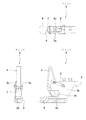
つぎに、上記布類投入機の特徴部分を図1〜図2に基づき説明するが、その特徴部分はハンガー81に取付けられるチャック2にある。
チャック2は、チャック本体3と爪片4を備えている。チャック本体3は前方から奥向きに凹んだ凹所3hが形成された側面視コ形のブロック体であり、基部3aと下突片3bと上突片3cとからなる。上突片3cの先端部にはピン7が通され、このピンに爪片4の略中間部が回動自在に支持されている。また、爪片4の上部とチャック本体3との間にはバネ8が張設されている。
Next, the characteristic portion of the cloth throwing machine will be described with reference to FIGS. 1 and 2, and the characteristic portion is on the
The
図2に示すように、バネ8で爪片4を引っ張って立てているときは、爪片4の下端部が下突片5の表面に当るので、シーツ等の布類Yをこの間に挟むことができる。
As shown in FIG. 2, when the
下突片3bの下面には、ガイド片9が取付けられている。このガイド片9の形状は任意であるが、図示の実施形態では、両側部に立壁が立ち上った断面U字形の形状であって、両側の立壁が下突片3bを挟み込んで取付けられている。また、ガイド片9の下突片3bを含むチャック本体3への取付けは任意であり、ビス止めや接着などの手段をとくに制限なく採用できる。
A
上記ガイド片9は幅が下突片3bより広く、長さも下突片3bより長く前方に突出している。
たとえば、幅は全幅が20〜40mm位で、下突片3bよりも2〜10mm位広い。また、前方へは下突片3bの先端より2〜40mm位突出している。
The
For example, the total width is about 20 to 40 mm, which is about 2 to 10 mm wider than the lower projecting
ガイド片9の先端部上面の高さは下突片3bの高さよりも、わずかに高くたとえば1mm程度高くされている。こうすることにより段差を付けておくと、シーツ等の布類Yを差し込んだとき、手の感覚でシーツ等の布類をきちんと奥まで挿入できることを感じとることができる。
The height of the upper surface of the tip of the
上記のように、ガイド片9が大きいと、作業員がチャック2の前方に立って、斜め上方から視線をみ降ろしたとき、上突片3aの先端とガイド片9の先端との間の間隔、すなわち、凹所3hの間口Wが広がるので下突片3bの存在場所を容易に認識できる。このため、シーツをチャック2につかませる作業が容易に間違いなく行えるので、作業能率が高くなる。
As described above, when the
図1に示すチャック2は、バネ8の弾発力で布類Y等をつかむように構成されている。爪片4は通常はバネ8で引っ張られているが、人手によって布類Yを押し込むと爪片4が押し動かされて、布類Yが凹所3hの奥まで入り、その状態で爪片4の底端と下突片3bとの間に布類Yを挟むことができる。
The
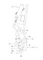
つぎに、上記チャック2における爪片4の開閉を自動で行う自動開閉機構を説明する。
図3に示すように、チャック2には爪開閉シリンダ5が取付けられている。この爪開閉シリンダはエアシリンダで構成されており、シリンダ本体51とピストンロッド52と押し金具53とからなる。押金具53はピストンロッド52の先端にボルトを介して取付けられており、押金具53の先端位置を長短に調整できる。このため、爪4の開度量も加減できる。
Next, an automatic opening / closing mechanism that automatically opens / closes the
As shown in FIG. 3, a claw opening /
爪開閉シリンダ5の伸縮動作は、センサを用いることにより自動化されている。
たとえば、シーツ等の布類Yをチャック2の凹所13hに挿入したことを非接触センサ(光電センサなど)で検知すると爪開閉シリンダ5を収縮させるようにしておくと、布類Yのチャック2への挿入に連動して爪4を閉じることができる。爪の開放は、チャック2が次工程機構に対し布類Yを受け渡す位置に来たことをリミットスイッチ等で検知して爪開閉シリンダ5を伸長させるように構成するとよい。
The expansion and contraction operation of the claw opening /
For example, if the non-contact sensor (photoelectric sensor or the like) detects that the cloth Y such as sheets is inserted into the
上記のような自動制御は、爪開閉シリンダ5のエアー回路に組み込んだ方向制御弁のソレノイドを、センサ信号の入力で駆動するような制御回路を用いることで可能である。
The automatic control as described above can be performed by using a control circuit that drives the solenoid of the directional control valve incorporated in the air circuit of the claw opening /
なお、チャック2は、エアシリンダで構成した回動シリンダ6により、支軸61を中心として前後方向(図中では左右方向)に揺動できるようになっている。これは、チャック2の開口側を作業員に向けて布類Yを差し込みやすくしたり、後ろ向きにして次工程機構へ布類Yを受け渡しやすくするためである。
The
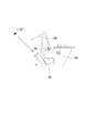
図4の(A)図は、チャック2が開いており、布類Yを挿入しようとする状態を示している。作業者は布類Yを手に持って布類Yの端縁を左右一対のチャック2の開口(凹所3h)に向け挿入する。このとき、ガイド片9が大きいと、作業員の視線を斜め上方から見降ろしても、下突片3bの存在場所を容易に認識できる点は前述のとおりである。
FIG. 4A shows a state in which the
図4の(B)図は、チャック2が閉じた状態を示している。チャック2の閉じる動作は既述のとおり、布類Yをチャック2の凹所13hに挿入したことをセンサで検知すると爪開閉シリンダ5が収縮して、布類Yのチャック2への挿入に連動して爪4を閉じることができる。このため、キャッチにおける爪の開動作が爪開閉シリンダによって行われるので、開動作のための人力操作が不要になることにより作業能率が向上する。
FIG. 4B shows a state in which the
上記実施形態は方形状の布類用の布類展開装置に適用されたものを説明したが、本発明の布類投入機はこれに限らず、方形でない衣類(浴衣や病衣など)用の投入装置にも適用することができる。
また、布類展開装置にあっても、図5に示す展開装置だけでなく、これと異なった構成の展開装置用の投入機にも本発明を適用できる。さらに、投入機自体の基本構成も図示のものに限られず、およそチャックを用いるものであれば、本発明を適用できる。
The above embodiment has been described as being applied to a cloth deploying device for square cloth, but the cloth throwing machine of the present invention is not limited to this, and is used for non-square cloth (yukata, sick clothes, etc.). It can also be applied to a throwing device.
Further, even in the cloth deploying device, the present invention can be applied not only to the deploying device shown in FIG. 5 but also to a throwing machine for a deploying device having a different configuration. Further, the basic configuration of the throwing machine itself is not limited to the one shown in the figure, and the present invention can be applied as long as it uses a chuck.
1 ハンガー
2 チャック
3 チャック本体
3a 基部
3b 下突片
3c 上突片
4 爪片
5 爪開閉シリンダ
8 バネ
1
Claims (3)
布類の端縁を把持するチャックを備えており、
該チャックは、布類の端縁を挿入する凹所の下面と上面に下突片と上突片が形成され、かつ該凹所内で爪が開閉する構造をもち、
前記下突片には、該下突片よりも幅が広く、かつ前記下突片の先端よりも前方に延出したガイド片を有する
ことを特徴とする布類投入機。 It is a throwing machine for grasping and hanging cloth and then handing it over to another device.
Equipped with a chuck that grips the edge of the cloth
The chuck has a structure in which a lower projecting piece and an upper projecting piece are formed on the lower surface and the upper surface of the recess into which the edge of the cloth is inserted, and the claws open and close in the recess.
A cloth throwing machine characterized in that the lower projecting piece has a guide piece that is wider than the lower projecting piece and extends forward from the tip of the lower projecting piece.
前記爪を常時閉方向に付勢するバネと、
前記爪を開方向に動作させる爪開閉シリンダとを備える
ことを特徴とする請求項1記載の布類投入機。 The chuck
A spring that constantly urges the claw in the closing direction,
The cloth throwing machine according to claim 1, further comprising a claw opening / closing cylinder for operating the claw in the opening direction.
ことを特徴とする請求項2記載の布類投入機。 It is provided with a sensor for detecting that a cloth piece is inserted into the recess in the chuck and a control circuit incorporating a sensor for contracting the claw opening / closing cylinder based on a detection signal from the sensor. The cloth throwing machine according to claim 2, which is characterized.
Priority Applications (1)
| Application Number | Priority Date | Filing Date | Title |
|---|---|---|---|
| JP2016147348A JP6780977B2 (en) | 2016-07-27 | 2016-07-27 | Cloth thrower |
Applications Claiming Priority (1)
| Application Number | Priority Date | Filing Date | Title |
|---|---|---|---|
| JP2016147348A JP6780977B2 (en) | 2016-07-27 | 2016-07-27 | Cloth thrower |
Publications (2)
| Publication Number | Publication Date |
|---|---|
| JP2018015201A JP2018015201A (en) | 2018-02-01 |
| JP6780977B2 true JP6780977B2 (en) | 2020-11-04 |
Family
ID=61076959
Family Applications (1)
| Application Number | Title | Priority Date | Filing Date |
|---|---|---|---|
| JP2016147348A Active JP6780977B2 (en) | 2016-07-27 | 2016-07-27 | Cloth thrower |
Country Status (1)
| Country | Link |
|---|---|
| JP (1) | JP6780977B2 (en) |
-
2016
- 2016-07-27 JP JP2016147348A patent/JP6780977B2/en active Active
Also Published As
| Publication number | Publication date |
|---|---|
| JP2018015201A (en) | 2018-02-01 |
Similar Documents
| Publication | Publication Date | Title |
|---|---|---|
| US10407822B2 (en) | Separator and stacker for textile articles | |
| JP3781376B1 (en) | Cloth stretch conveying method and apparatus | |
| EP3181748B1 (en) | Cloth spreading device | |
| WO2007049501A1 (en) | Hanger and clothes folding machine | |
| JP2010273732A (en) | Apparatus for automatically developing/charging textile products | |
| JP2011036312A (en) | Square cloths spreading apparatus | |
| US7827709B2 (en) | Linen spreader apparatus and method | |
| JP2022544535A (en) | Method and system for feeding flatwork articles to a transfer conveyor and/or flatwork processing equipment | |
| JP6780977B2 (en) | Cloth thrower | |
| JP7064841B2 (en) | Cloth unfolding device | |
| JP5624927B2 (en) | Clothes folding machine | |
| JP5089345B2 (en) | One-touch trouser hanger | |
| JP6932001B2 (en) | Cloth thrower and cloth unfolding device | |
| EP3677714A1 (en) | Fabric clamping chuck and fabric handling device | |
| KR20180034855A (en) | Laundry transferring robot arm | |
| JP5022674B2 (en) | Clothing shaping supply device | |
| JP3379846B2 (en) | Fully automatic finishing method and apparatus for laundry with rectangular cloth pieces | |
| JP7043174B2 (en) | Cloth thrower and cloth deployer | |
| JP2016106892A (en) | Square cloth spreading apparatus | |
| NL2023651B1 (en) | Method and system feeding a flatwork item to a transport conveyor and/or a flatwork treating device | |
| JP7064963B2 (en) | Cloth unfolding device | |
| JP6704362B2 (en) | Camera system for cloth gripping device | |
| JP6981831B2 (en) | Cloth repeater and cloth processing equipment | |
| JP7018326B2 (en) | Cloth unfolding device | |
| JP6730097B2 (en) | Cloth spreading device |
Legal Events
| Date | Code | Title | Description |
|---|---|---|---|
| A621 | Written request for application examination |
Free format text: JAPANESE INTERMEDIATE CODE: A621 Effective date: 20190605 |
|
| A131 | Notification of reasons for refusal |
Free format text: JAPANESE INTERMEDIATE CODE: A131 Effective date: 20200728 |
|
| A977 | Report on retrieval |
Free format text: JAPANESE INTERMEDIATE CODE: A971007 Effective date: 20200722 |
|
| TRDD | Decision of grant or rejection written | ||
| A01 | Written decision to grant a patent or to grant a registration (utility model) |
Free format text: JAPANESE INTERMEDIATE CODE: A01 Effective date: 20201006 |
|
| A61 | First payment of annual fees (during grant procedure) |
Free format text: JAPANESE INTERMEDIATE CODE: A61 Effective date: 20201015 |
|
| R150 | Certificate of patent or registration of utility model |
Ref document number: 6780977 Country of ref document: JP Free format text: JAPANESE INTERMEDIATE CODE: R150 |
|
| R250 | Receipt of annual fees |
Free format text: JAPANESE INTERMEDIATE CODE: R250 |