JP6000641B2 - Manipulator system - Google Patents
Manipulator system Download PDFInfo
- Publication number
- JP6000641B2 JP6000641B2 JP2012116740A JP2012116740A JP6000641B2 JP 6000641 B2 JP6000641 B2 JP 6000641B2 JP 2012116740 A JP2012116740 A JP 2012116740A JP 2012116740 A JP2012116740 A JP 2012116740A JP 6000641 B2 JP6000641 B2 JP 6000641B2
- Authority
- JP
- Japan
- Prior art keywords
- opening
- unit
- closing
- master
- input
- Prior art date
- Legal status (The legal status is an assumption and is not a legal conclusion. Google has not performed a legal analysis and makes no representation as to the accuracy of the status listed.)
- Active
Links
Images


Classifications
-
- B—PERFORMING OPERATIONS; TRANSPORTING
- B25—HAND TOOLS; PORTABLE POWER-DRIVEN TOOLS; MANIPULATORS
- B25J—MANIPULATORS; CHAMBERS PROVIDED WITH MANIPULATION DEVICES
- B25J13/00—Controls for manipulators
- B25J13/02—Hand grip control means
-
- G—PHYSICS
- G06—COMPUTING; CALCULATING OR COUNTING
- G06F—ELECTRIC DIGITAL DATA PROCESSING
- G06F3/00—Input arrangements for transferring data to be processed into a form capable of being handled by the computer; Output arrangements for transferring data from processing unit to output unit, e.g. interface arrangements
- G06F3/01—Input arrangements or combined input and output arrangements for interaction between user and computer
-
- A—HUMAN NECESSITIES
- A61—MEDICAL OR VETERINARY SCIENCE; HYGIENE
- A61B—DIAGNOSIS; SURGERY; IDENTIFICATION
- A61B17/00—Surgical instruments, devices or methods, e.g. tourniquets
- A61B17/28—Surgical forceps
- A61B17/29—Forceps for use in minimally invasive surgery
-
- A—HUMAN NECESSITIES
- A61—MEDICAL OR VETERINARY SCIENCE; HYGIENE
- A61B—DIAGNOSIS; SURGERY; IDENTIFICATION
- A61B17/00—Surgical instruments, devices or methods, e.g. tourniquets
- A61B17/32—Surgical cutting instruments
- A61B17/320016—Endoscopic cutting instruments, e.g. arthroscopes, resectoscopes
- A61B17/32002—Endoscopic cutting instruments, e.g. arthroscopes, resectoscopes with continuously rotating, oscillating or reciprocating cutting instruments
-
- A—HUMAN NECESSITIES
- A61—MEDICAL OR VETERINARY SCIENCE; HYGIENE
- A61B—DIAGNOSIS; SURGERY; IDENTIFICATION
- A61B18/00—Surgical instruments, devices or methods for transferring non-mechanical forms of energy to or from the body
- A61B18/04—Surgical instruments, devices or methods for transferring non-mechanical forms of energy to or from the body by heating
- A61B18/12—Surgical instruments, devices or methods for transferring non-mechanical forms of energy to or from the body by heating by passing a current through the tissue to be heated, e.g. high-frequency current
- A61B18/14—Probes or electrodes therefor
- A61B18/1402—Probes for open surgery
-
- A—HUMAN NECESSITIES
- A61—MEDICAL OR VETERINARY SCIENCE; HYGIENE
- A61B—DIAGNOSIS; SURGERY; IDENTIFICATION
- A61B34/00—Computer-aided surgery; Manipulators or robots specially adapted for use in surgery
- A61B34/30—Surgical robots
-
- A—HUMAN NECESSITIES
- A61—MEDICAL OR VETERINARY SCIENCE; HYGIENE
- A61B—DIAGNOSIS; SURGERY; IDENTIFICATION
- A61B34/00—Computer-aided surgery; Manipulators or robots specially adapted for use in surgery
- A61B34/30—Surgical robots
- A61B34/37—Master-slave robots
-
- A—HUMAN NECESSITIES
- A61—MEDICAL OR VETERINARY SCIENCE; HYGIENE
- A61B—DIAGNOSIS; SURGERY; IDENTIFICATION
- A61B34/00—Computer-aided surgery; Manipulators or robots specially adapted for use in surgery
- A61B34/70—Manipulators specially adapted for use in surgery
- A61B34/74—Manipulators with manual electric input means
-
- A—HUMAN NECESSITIES
- A61—MEDICAL OR VETERINARY SCIENCE; HYGIENE
- A61B—DIAGNOSIS; SURGERY; IDENTIFICATION
- A61B34/00—Computer-aided surgery; Manipulators or robots specially adapted for use in surgery
- A61B34/70—Manipulators specially adapted for use in surgery
- A61B34/76—Manipulators having means for providing feel, e.g. force or tactile feedback
-
- A—HUMAN NECESSITIES
- A61—MEDICAL OR VETERINARY SCIENCE; HYGIENE
- A61B—DIAGNOSIS; SURGERY; IDENTIFICATION
- A61B46/00—Surgical drapes
- A61B46/10—Surgical drapes specially adapted for instruments, e.g. microscopes
-
- B—PERFORMING OPERATIONS; TRANSPORTING
- B25—HAND TOOLS; PORTABLE POWER-DRIVEN TOOLS; MANIPULATORS
- B25J—MANIPULATORS; CHAMBERS PROVIDED WITH MANIPULATION DEVICES
- B25J3/00—Manipulators of master-slave type, i.e. both controlling unit and controlled unit perform corresponding spatial movements
- B25J3/04—Manipulators of master-slave type, i.e. both controlling unit and controlled unit perform corresponding spatial movements involving servo mechanisms
-
- B—PERFORMING OPERATIONS; TRANSPORTING
- B25—HAND TOOLS; PORTABLE POWER-DRIVEN TOOLS; MANIPULATORS
- B25J—MANIPULATORS; CHAMBERS PROVIDED WITH MANIPULATION DEVICES
- B25J9/00—Programme-controlled manipulators
- B25J9/16—Programme controls
- B25J9/1679—Programme controls characterised by the tasks executed
- B25J9/1689—Teleoperation
-
- A—HUMAN NECESSITIES
- A61—MEDICAL OR VETERINARY SCIENCE; HYGIENE
- A61B—DIAGNOSIS; SURGERY; IDENTIFICATION
- A61B17/00—Surgical instruments, devices or methods, e.g. tourniquets
- A61B17/068—Surgical staplers, e.g. containing multiple staples or clamps
-
- A—HUMAN NECESSITIES
- A61—MEDICAL OR VETERINARY SCIENCE; HYGIENE
- A61B—DIAGNOSIS; SURGERY; IDENTIFICATION
- A61B17/00—Surgical instruments, devices or methods, e.g. tourniquets
- A61B2017/00017—Electrical control of surgical instruments
- A61B2017/00115—Electrical control of surgical instruments with audible or visual output
- A61B2017/00119—Electrical control of surgical instruments with audible or visual output alarm; indicating an abnormal situation
-
- A—HUMAN NECESSITIES
- A61—MEDICAL OR VETERINARY SCIENCE; HYGIENE
- A61B—DIAGNOSIS; SURGERY; IDENTIFICATION
- A61B17/00—Surgical instruments, devices or methods, e.g. tourniquets
- A61B2017/00477—Coupling
-
- A—HUMAN NECESSITIES
- A61—MEDICAL OR VETERINARY SCIENCE; HYGIENE
- A61B—DIAGNOSIS; SURGERY; IDENTIFICATION
- A61B17/00—Surgical instruments, devices or methods, e.g. tourniquets
- A61B2017/00477—Coupling
- A61B2017/00482—Coupling with a code
-
- A—HUMAN NECESSITIES
- A61—MEDICAL OR VETERINARY SCIENCE; HYGIENE
- A61B—DIAGNOSIS; SURGERY; IDENTIFICATION
- A61B46/00—Surgical drapes
- A61B46/20—Surgical drapes specially adapted for patients
- A61B46/23—Surgical drapes specially adapted for patients with means to retain or hold surgical implements
-
- Y—GENERAL TAGGING OF NEW TECHNOLOGICAL DEVELOPMENTS; GENERAL TAGGING OF CROSS-SECTIONAL TECHNOLOGIES SPANNING OVER SEVERAL SECTIONS OF THE IPC; TECHNICAL SUBJECTS COVERED BY FORMER USPC CROSS-REFERENCE ART COLLECTIONS [XRACs] AND DIGESTS
- Y10—TECHNICAL SUBJECTS COVERED BY FORMER USPC
- Y10S—TECHNICAL SUBJECTS COVERED BY FORMER USPC CROSS-REFERENCE ART COLLECTIONS [XRACs] AND DIGESTS
- Y10S901/00—Robots
- Y10S901/02—Arm motion controller
- Y10S901/06—Communication with another machine
- Y10S901/08—Robot
-
- Y—GENERAL TAGGING OF NEW TECHNOLOGICAL DEVELOPMENTS; GENERAL TAGGING OF CROSS-SECTIONAL TECHNOLOGIES SPANNING OVER SEVERAL SECTIONS OF THE IPC; TECHNICAL SUBJECTS COVERED BY FORMER USPC CROSS-REFERENCE ART COLLECTIONS [XRACs] AND DIGESTS
- Y10—TECHNICAL SUBJECTS COVERED BY FORMER USPC
- Y10S—TECHNICAL SUBJECTS COVERED BY FORMER USPC CROSS-REFERENCE ART COLLECTIONS [XRACs] AND DIGESTS
- Y10S901/00—Robots
- Y10S901/02—Arm motion controller
- Y10S901/09—Closed loop, sensor feedback controls arm movement
-
- Y—GENERAL TAGGING OF NEW TECHNOLOGICAL DEVELOPMENTS; GENERAL TAGGING OF CROSS-SECTIONAL TECHNOLOGIES SPANNING OVER SEVERAL SECTIONS OF THE IPC; TECHNICAL SUBJECTS COVERED BY FORMER USPC CROSS-REFERENCE ART COLLECTIONS [XRACs] AND DIGESTS
- Y10—TECHNICAL SUBJECTS COVERED BY FORMER USPC
- Y10S—TECHNICAL SUBJECTS COVERED BY FORMER USPC CROSS-REFERENCE ART COLLECTIONS [XRACs] AND DIGESTS
- Y10S901/00—Robots
- Y10S901/30—End effector
-
- Y—GENERAL TAGGING OF NEW TECHNOLOGICAL DEVELOPMENTS; GENERAL TAGGING OF CROSS-SECTIONAL TECHNOLOGIES SPANNING OVER SEVERAL SECTIONS OF THE IPC; TECHNICAL SUBJECTS COVERED BY FORMER USPC CROSS-REFERENCE ART COLLECTIONS [XRACs] AND DIGESTS
- Y10—TECHNICAL SUBJECTS COVERED BY FORMER USPC
- Y10T—TECHNICAL SUBJECTS COVERED BY FORMER US CLASSIFICATION
- Y10T29/00—Metal working
- Y10T29/49—Method of mechanical manufacture
- Y10T29/49826—Assembling or joining
-
- Y—GENERAL TAGGING OF NEW TECHNOLOGICAL DEVELOPMENTS; GENERAL TAGGING OF CROSS-SECTIONAL TECHNOLOGIES SPANNING OVER SEVERAL SECTIONS OF THE IPC; TECHNICAL SUBJECTS COVERED BY FORMER USPC CROSS-REFERENCE ART COLLECTIONS [XRACs] AND DIGESTS
- Y10—TECHNICAL SUBJECTS COVERED BY FORMER USPC
- Y10T—TECHNICAL SUBJECTS COVERED BY FORMER US CLASSIFICATION
- Y10T74/00—Machine element or mechanism
- Y10T74/18—Mechanical movements
- Y10T74/18056—Rotary to or from reciprocating or oscillating
Landscapes
- Health & Medical Sciences (AREA)
- Engineering & Computer Science (AREA)
- Surgery (AREA)
- Life Sciences & Earth Sciences (AREA)
- Robotics (AREA)
- General Health & Medical Sciences (AREA)
- Veterinary Medicine (AREA)
- Biomedical Technology (AREA)
- Heart & Thoracic Surgery (AREA)
- Medical Informatics (AREA)
- Molecular Biology (AREA)
- Animal Behavior & Ethology (AREA)
- Public Health (AREA)
- Nuclear Medicine, Radiotherapy & Molecular Imaging (AREA)
- Mechanical Engineering (AREA)
- General Engineering & Computer Science (AREA)
- Physics & Mathematics (AREA)
- Theoretical Computer Science (AREA)
- Orthopedic Medicine & Surgery (AREA)
- Ophthalmology & Optometry (AREA)
- Human Computer Interaction (AREA)
- General Physics & Mathematics (AREA)
- Plasma & Fusion (AREA)
- Otolaryngology (AREA)
- Manipulator (AREA)
Description
本発明は、マニピュレータシステムに関する。例えば、マスタスレーブ方式の医療用のマニピュレータシステムに関する。 The present invention relates to a manipulator system. For example, the present invention relates to a medical slave manipulator system.
従来、外科手術の手術支援を行うための医療用マニピュレータとして、マスタスレーブ方式のマニピュレータシステムが知られている。このような医療用マニピュレータでは、スレーブマニピュレータに装着された手術に用いる器具(スレーブ動作部)、例えば、鉗子や持針器などの動作を操作入力するマスタグリップ(マスタ操作部)を備え、操作者である外科医がマスタグリップを操作することにより、マスタグリップの動きをこの器具に伝達する。
このようなマニピュレータシステムとして、例えば、特許文献1には、入力ハンドルを開閉することにより、エンドエフェクタの開閉動作を制御する医療用ロボットシステムが記載されている。
Conventionally, a master-slave manipulator system is known as a medical manipulator for performing surgical support of a surgical operation. Such a medical manipulator includes a master grip (master operation unit) for operating and inputting an operation of a surgical instrument (slave operation unit) attached to the slave manipulator, for example, a forceps or a needle holder. By operating the master grip, the surgeon transmits the movement of the master grip to the instrument.
As such a manipulator system, for example,
しかしながら、上記のような従来のマニピュレータシステムには、以下のような問題があった。
例えば、スレーブ動作部が、鉗子などからなり、生体組織や術具などを把持する場合、これら被把持物の大きさや硬さは様々である。
一方、マスタ操作部を操作する操作者は、画像情報などの限られた情報から、被把持物の大きさや硬さを判断するため、マスタ操作部の操作入力が実際の被把持物に適合しない場合がある。例えば、操作者が操作入力する開閉角が把持に必要な開閉角に比べて小さすぎる場合、スレーブ動作部は被把持物を把持してからも指令値通りに閉じようとする。このとき、被把持物が硬いとそれ以上閉じることができなくなり、開閉角がマスタ操作部の操作入力に応じた開閉角とずれてしまう。
このとき、一時的に連動制御が停止状態になる。その後、閉じ操作ができないことに気がついた操作者が開く操作を行うと、スレーブ動作部の開閉角がマスタ操作部の操作入力に応じた開閉角に一致した瞬間に、連動制御が再開されることになる。
この場合、操作者は、いつ連動制御が再開されるか把握できないため、予期できない動作が起こってしまうおそれがある。このため、適正な作業が行えず、作業に支障をきたすおそれがあるという問題がある。例えば、被把持物の把持状態が急に解除されて被把持物を落としてしまったり、スレーブ動作部が予期しない動きをして外科手術に支障を来したりするおそれがある。
However, the conventional manipulator system as described above has the following problems.
For example, when the slave operation unit is composed of forceps and the like and grips a living tissue or a surgical instrument, the size and hardness of these objects to be gripped vary.
On the other hand, since the operator who operates the master operation unit determines the size and hardness of the object to be grasped from limited information such as image information, the operation input of the master operation unit does not match the actual object to be grasped. There is a case. For example, when the opening / closing angle input by the operator is too small compared to the opening / closing angle necessary for gripping, the slave operating unit tries to close the commanded value even after gripping the object to be gripped. At this time, if the object to be grasped is hard, the object cannot be closed any more, and the opening / closing angle deviates from the opening / closing angle corresponding to the operation input of the master operation unit.
At this time, the interlock control is temporarily stopped. After that, when an operator who realizes that the closing operation cannot be performed performs an opening operation, the interlock control is resumed at the moment when the opening / closing angle of the slave operation unit matches the opening / closing angle corresponding to the operation input of the master operation unit. become.
In this case, since the operator cannot grasp when the interlock control is resumed, an unexpected operation may occur. For this reason, there is a problem that proper work cannot be performed and there is a possibility that the work may be hindered. For example, the grasping state of the object to be grasped may be suddenly released and the object to be grasped may be dropped, or the slave operation unit may move unexpectedly and hinder the surgical operation.
本発明は、上記のような問題に鑑みてなされたものであり、スレーブ動作部の動作がマスタ操作部の操作入力に応じた動作からずれた場合に、作業に支障を来すことなくスレーブ動作部の連動を再開できるマニピュレータシステムを提供することを目的とする。 The present invention has been made in view of the above-described problems. When the operation of the slave operation unit deviates from the operation corresponding to the operation input of the master operation unit, the slave operation is not hindered. An object of the present invention is to provide a manipulator system capable of resuming the interlocking of parts.
上記の課題を解決するために、本発明のマニピュレータシステムは、操作者が操作入力を行うマスタ操作部と、前記操作入力に対応して動作可能なスレーブ動作部と、前記操作入力を解析し、該操作入力に連動して前記スレーブ動作部を動作させる制御を行う連動制御部と、を有するマニピュレータシステムであって、前記操作者が操作可能であり、操作されたときに、前記マスタ操作部の前記操作入力に基づく前記スレーブ動作部の連動を許可するモードに入る連動許可モード信号を前記連動制御部に送出する連動許可入力部を備え、前記マスタ操作部は、前記操作入力を行うため、開閉可能に設けられた操作部材と、該操作部材の開閉角を検出し、前記操作部材の開閉角の検出値を前記連動制御部に送出するマスタ角度検出部と、を備え、前記スレーブ動作部は、開閉可能に設けられた開閉動作部と、該開閉動作部の開閉角を検出し、前記開閉動作部の開閉角の検出値を前記連動制御部に送出するスレーブ角度検出部と、を備え、前記連動許可入力部は、前記操作部材が最大限開く位置に移動したことを検出して、前記連動許可モード信号を発生する位置検出スイッチを備え、前記連動制御部は、前記スレーブ動作部の動作が前記操作入力に応じた動作からずれた場合に、連動制御を停止して、前記マスタ操作部の前記操作入力と前記スレーブ動作部の動作状態とを監視し、前記位置検出スイッチが発生した前記連動許可モード信号を受信後であって、前記操作部材の開閉角の検出値と前記開閉動作部の開閉角の検出値とが対応したことによって前記操作入力が前記動作状態に合致したことを検知したとき、かつ前記操作部材の開閉角の検出値が前記操作部材の閉じ方向に変化している場合に、前記スレーブ動作部の動作を前記操作入力に応じた動作に連動させる構成とする。 In order to solve the above problems, the manipulator system of the present invention analyzes a master operation unit where an operator performs an operation input, a slave operation unit operable in response to the operation input, and the operation input, A manipulator system having an interlock control unit that controls the slave operation unit to operate in conjunction with the operation input, the manipulator system being operable and operated by the operator. An interlocking permission input unit that sends an interlocking permission mode signal that enters a mode for allowing interlocking of the slave operation unit based on the operation input to the interlocking control unit, and the master operation unit opens and closes to perform the operation input. An operation member provided in a possible manner, and a master angle detection unit that detects an opening / closing angle of the operation member and sends a detection value of the opening / closing angle of the operation member to the interlock control unit. The slave operation unit includes an open / close operation unit provided to be openable and closable, and a slave angle detection unit that detects an open / close angle of the open / close operation unit and sends a detection value of the open / close angle of the open / close operation unit to the interlock control unit The interlocking permission input unit includes a position detection switch that detects that the operating member has moved to the maximum opening position and generates the interlocking permission mode signal. When the operation of the slave operation unit deviates from the operation corresponding to the operation input, the interlock control is stopped, the operation input of the master operation unit and the operation state of the slave operation unit are monitored, and the position detection is performed. even after receiving the interlocking permission mode signal switch occurs, the operating state the operation input by the detected value of the opening angle and the detected value of the opening and closing angle of the opening and closing operation portions corresponding to said operating member When is detected that the match, and when the detected value of the opening and closing angle of the operation member is changed in the closing direction of the operating member, to interlock the operation of the slave operation unit to the action according to the operation input The configuration.
また、本発明のマニピュレータシステムでは、前記連動許可入力部は、前記操作部材が最大限開く位置に移動したことを検出して、前記連動許可モード信号を発生する位置検出スイッチからなることが好ましい。 In the manipulator system of the present invention, it is preferable that the interlock permission input unit includes a position detection switch that detects that the operation member has moved to a position where the operation member is fully opened and generates the interlock permission mode signal.
また、本発明のマニピュレータシステムでは、前記連動許可入力部は、前記マスタ操作部の表面に設けられた入力スイッチからなることが好ましい。 In the manipulator system of the present invention, it is preferable that the interlocking permission input unit includes an input switch provided on the surface of the master operation unit.
また、本発明のマニピュレータシステムでは、前記連動許可入力部は、前記マスタ操作部と別体に設けられた入力スイッチからなることが好ましい。 In the manipulator system of the present invention, it is preferable that the interlocking permission input unit includes an input switch provided separately from the master operation unit.
また、本発明のマニピュレータシステムでは、前記入力スイッチは、フットスイッチからなることが好ましい。 In the manipulator system of the present invention, it is preferable that the input switch is a foot switch.
また、本発明のマニピュレータシステムでは、前記連動制御部は、前記連動許可モード信号の受信後であって、前記操作部材の開閉角の検出値と前記開閉動作部の開閉角の検出値とが対応したとき、かつ前記操作部材の開閉角の検出値が前記操作部材の開き方向に変化している場合にも、前記スレーブ動作部を前記操作入力に応じた動作に連動させることが可能であり、前記開き方向に変化している場合に連動させるか、前記閉じ方向に変化している場合に連動させるかを選択可能であることが好ましい。
Further, in the manipulator system of the present invention, the pre-Symbol interlocking control unit, even after the reception of the interlocking permission mode signal, and the detected value of the opening and closing angle of the detected value and the opening and closing operation of the opening and closing angle of the operation member when corresponding, and wherein when the detected value of the opening and closing angle of the operation member is changed in direction opening of the operating member also can be linked to the slave operation unit to the action according to the operation input It is preferable that it is possible to select whether to interlock when changing in the opening direction or interlocking when changing in the closing direction.
本発明のマニピュレータシステムによれば、操作者が操作可能な連動許可入力部を備えるため、予期しないタイミングで連動動作が起こることを防止でき、スレーブ動作部の動作がマスタ操作部の操作入力に応じた動作からずれた場合に、作業に支障を来すことなくスレーブ動作部の連動を再開できるという効果を奏する。 According to the manipulator system of the present invention, since the interlocking permission input unit that can be operated by the operator is provided, it is possible to prevent the interlocking operation from occurring at an unexpected timing, and the operation of the slave operation unit corresponds to the operation input of the master operation unit. When the operation deviates from the operation, the slave operation unit can be resumed without interfering with the work.
以下では、本発明の実施形態について添付図面を参照して説明する。
まず、本実施形態のマニピュレータシステムについて説明する。
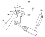
図1は、本発明の実施形態のマニピュレータシステムの概略構成を示す模式的な斜視図である。図2は、図1におけるマニピュレータシステムに含まれる他のマスタ操作部を示す模式的な斜視図である。図3は、本発明の実施形態のマニピュレータシステムの主要部のシステム構成を示す模式的なシステム構成図である。
Embodiments of the present invention will be described below with reference to the accompanying drawings.
First, the manipulator system of this embodiment will be described.
FIG. 1 is a schematic perspective view showing a schematic configuration of a manipulator system according to an embodiment of the present invention. FIG. 2 is a schematic perspective view showing another master operation unit included in the manipulator system in FIG. 1. FIG. 3 is a schematic system configuration diagram showing a system configuration of a main part of the manipulator system according to the embodiment of the present invention.
図1(一部の構成は図2、3)に示すように、本実施形態のマスタスレーブマニピュレータ500(マニピュレータシステム)は、例えば、外科手術を行うための医療用マニピュレータであり、スレーブマニピュレータ300と、操作者Opによる操作入力を受けてスレーブマニピュレータ300の動作を遠隔操作する操作入力装置100とを備える。
As shown in FIG. 1 (some configurations are FIGS. 2 and 3), a master-slave manipulator 500 (manipulator system) of this embodiment is a medical manipulator for performing a surgical operation, for example, And an
スレーブマニピュレータ300は、処置具302と、処置具302を患者Pの周囲で可動支持するスレーブアーム301と、処置具302およびスレーブアーム301の可動部の動作を制御するスレーブ制御部303と、処置具302およびスレーブアーム301を支持する支持体304とを備える。
なお、図1は模式図のため、処置具302、スレーブアーム301は、それぞれ1台ずつ設けられている場合の例が図示されているが、処置具302、スレーブアーム301はそれぞれ複数設けられていてもよい。複数設けられている場合には、操作者Opは、そのうちの2台を選択し、右手と左手を用いて、2台を同時に操作することが可能である。
また機能ブロック図の一部の信号の図示も省略している。
The
Since FIG. 1 is a schematic diagram, an example in which one
Also, illustration of some signals in the functional block diagram is omitted.
処置具302は、外科手術に用いる種々の術具や処置具を採用することができるが、以下では、一例として、図3に示すように、軸状部312の先端(患者Pの体腔に向かう側の端部)に設けられて開閉動作を行う開閉部311(スレーブ動作部、開閉動作部)と、開閉部311を開閉する開閉駆動部313とを備える場合の例で説明する。
このような処置具302の例としては、例えば、鉗子や持針器などを挙げることができる。
As the
Examples of such a
開閉部311は、回動支軸311cを中心として開閉中心軸線O311に対して左右対称に開閉する一対の処置具片311bを備える。
なお、図3では、開閉中心軸線O311が軸状部312の中心軸線と整列しているように描いている。ただし、開閉部311は、図示略の関節を介して軸状部312と連結されていてもよく、この場合には、開閉中心軸線O311は、軸状部312の中心軸線に対して傾斜する姿勢を取ることも可能である。
The opening /
In FIG. 3, the opening / closing center axis O 311 is drawn so as to be aligned with the center axis of the shaft-shaped
以下では、開閉部311の開閉角として、開閉中心軸線O311と各処置具片311bの把持面311a同士のなす角度θSを用いることにする。すなわち、角度θSは、各把持面311aのなす角の半分である。
このため、処置具片311bが開き方向に移動すると角度θSは増大する。処置具片311bが閉じ方向に移動すると、角度θSは減少する。
ただし、この開閉角の定義は、一例であって、例えば、各把持面311aのなす角である角度2θSを採用してもよい。
Hereinafter, as the opening / closing angle of the opening /
For this reason, when the
However, this definition of the opening / closing angle is an example, and for example, an angle 2θ S that is an angle formed by each
開閉駆動部313は、その動作が、制御部400から送出される駆動指令値403に基づいてスレーブ制御部303から送出される駆動信号313aにより制御される。このため、開閉駆動部313は、後述するスレーブ制御部303を介して、制御部400と電気的に接続されている。
開閉駆動部313の構成としては、開閉部311を開閉させる適宜のアクチュエータを採用することができる。
また、開閉駆動部313は、開閉駆動部313の開閉角を検出するエンコーダ314(スレーブ角度検出部)を備えている。
The operation of the opening /
As the configuration of the opening /
The opening /
エンコーダ314は、検出された開閉角に対応する出力信号314aを生成し、スレーブ制御部303に送出できるようになっている。
エンコーダ314の構成は特に限定されず、例えば、開閉部311の回動量を直接的に検出するロータリエンコーダであってもよいし、開閉部311の開閉動作に連動する直動部材の移動量を検出するリニアエンコーダやこの直動移動を回動量に変換して検出するロータリエンコーダであってもよい。
The
The configuration of the
また、エンコーダ314は、アブソリュート型でもよいし、インクリメント型でもよい。
インクリメント型を採用する場合には、適宜の位置校正手段を設け、この位置校正手段により、処置具片311bが一定の校正位置に達したかどうかを監視し、処置具片311bが校正位置に達したときに、エンコーダ314の出力信号314aをリセットする構成とすることが好ましい。このような構成によれば、校正位置を通過するたびに出力信号314aを校正することができるため、インクリメント型であっても、開閉部311の開閉角を正確に検出することができる。
The
In the case of adopting the increment type, appropriate position calibration means is provided, and by this position calibration means, it is monitored whether or not the
スレーブアーム301は、処置具302を適宜の位置および姿勢で保持する多関節アームからなり、スレーブ制御部303に電気的に接続され、スレーブ制御部303からの制御信号に応じて動作が制御されるようになっている。
The
スレーブ制御部303は、図1に示すように、後述するマニピュレータ制御部402からの制御信号に基づいて、スレーブマニピュレータ300の制御を行うとともに、スレーブマニピュレータ300から送信される各可動部の位置情報や制御に必要な検知信号等をマニピュレータ制御部402に送出するものである。このため、スレーブ制御部303は、後述する制御部400のマニピュレータ制御部402およびスレーブマニピュレータ300の各可動部と電気的に接続されている。
例えば、スレーブ制御部303は、処置具302の開閉部311に対して、駆動指令値403に基づいて開閉部311の開閉を行うための駆動信号313aを送出して、開閉制御を行う。
また、スレーブ制御部303は、エンコーダ314から出力信号314aを取得し、マニピュレータ制御部402に転送する。
As shown in FIG. 1, the
For example, the
In addition, the
操作入力装置100は、図1に示すように、マスタ入力部200と、制御部400(連動制御部)とを備える。
マスタ入力部200は、操作者Opによる操作をスレーブマニピュレータ300に伝達するマスタとして機能するものであって、表示部201(情報表示部)と、マスタアーム202と、マスタグリップ203L、203R(マスタ操作部)とを有している。
As illustrated in FIG. 1, the
The
表示部201は、図示略のカメラおよび制御部400と電気的に接続されており、カメラや制御部400からの情報を表示して、操作者Opが見られるようにするものである。
表示部201の表示の種類としては、例えば、カメラによって撮影される患者Pの術部およびその近傍の映像、例えば、フットスイッチ等の不図示の入力手段による操作入力を行う操作入力画面、操作者Opに対する種々の情報、ガイダンス、警告メッセージなどの文字や画像などを挙げることができる。
The
Examples of the display type of the
マスタアーム202は、スレーブマニピュレータ300におけるスレーブアーム301の位置および姿勢を操作するための操作者Opの操作をスレーブマニピュレータ300に伝達するものであり、制御部400と通信可能に接続されている。
本実施形態のマスタアーム202は、アーム基端部202bが、例えば、表示部201の下部等のマスタ入力部200内の定位置に連結された2本の多関節アーム202L(図1参照)および多関節アーム202R(図2参照)からなる。
多関節アーム202L、202Rは、それぞれ操作者Opが表示部201を見ながら操作できるように表示部201の前側に配置されている。
また、多関節アーム202L、202Rは、それぞれ、操作者Opの左手、右手による操作入力に対応している。
多関節アーム202L、202Rにおいて操作者Op側となるアーム先端部202aには、操作者Opが把持して操作入力を行うマスタグリップ203L、203Rが設けられている。
多関節アーム202L、202Rは、それぞれ、関節ごとに関節の動作量を検知するエンコーダを備えており、各エンコーダの出力を関節ごとの操作信号として制御部400に送出できるようになっている。
The
The
The
The
Master grips 203L and 203R that the operator Op holds and inputs operations are provided at the
Each of the
マスタグリップ203L、203Rは、それぞれ操作者Opの左手、右手の操作により、それぞれ、多関節アーム202L、202Rに対応するスレーブアーム301と、このスレーブアーム301に設けられた処置具302とに対する操作入力を行うものである。
マスタグリップ203L、203Rは、それぞれ左手、右手で把持や操作が容易となるように互いに面対称となる形状に設けることができるが、以下では、一例として、いずれも同一形状のマスタグリップ1(図3参照)からなるものとして説明する。
The master grips 203L and 203R are input to the
The master grips 203L and 203R can be provided in shapes that are symmetrical with each other so that they can be easily grasped and operated by the left hand and the right hand, respectively, but in the following, as an example, the master grips 1 (see FIG. 3).
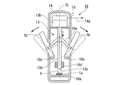
マスタグリップ1の概略構成は、図3に示すように、グリップ部1a、筐体部1d、操作ハンドル1b(操作部材)、ばね3、エンコーダ4(マスタ角度検出部)、および位置検出スイッチ6(連動許可入力部)を備える。
なお、図3は、図2におけるA視の平面図として描かれているが、図3は模式図のため、例えば、図2に示された筐体部1dの図示は省略している。
As shown in FIG. 3, a schematic configuration of the
Note that FIG. 3 is depicted as a plan view as viewed in A in FIG. 2, but FIG. 3 is a schematic diagram, and for example, illustration of the
グリップ部1aは、図2に示すように、操作者Opが片手で把持する筒状体であり、一方の端部に、アーム先端部202aに向かって延出された筐体部1dを備える。
筐体部1dは、その先端部において、アーム先端部202aと連結されている。
また、グリップ部1aの端部には、一対の操作ハンドル1bが筐体部1dを挟んで可動支持され、操作ハンドル1bをV字状に開いた状態の開閉角を変えられるようになっている。
本実施形態では、図3に示すように、各操作ハンドル1bの一端部が、グリップ部1aの内部に設けられた回動支軸1cによって回動可能に支持されている。
As shown in FIG. 2, the
The
In addition, a pair of operation handles 1b are movably supported at the end of the
In this embodiment, as shown in FIG. 3, one end portion of each
各操作ハンドル1bは、操作者Opの指を係止することによって、開閉動作を行うことができれば、棒状、板状等の適宜の形状を採用することができる。例えば、操作者Opの把持位置を特定できるように、凹凸部が形成されていてもよい。また、図示は省略するが、操作者Opの指のうごきに操作ハンドル1bが追従しやすいように、例えば、操作を行う指を開閉方向において係止する突起部や、指を挿入する指挿入部などを設けた構成としてもよい。
As long as each operation handle 1b can be opened and closed by engaging the finger of the operator Op, an appropriate shape such as a rod shape or a plate shape can be adopted. For example, an uneven portion may be formed so that the gripping position of the operator Op can be specified. Although illustration is omitted, for example, a protrusion that locks the finger that performs the operation in the opening and closing direction, or a finger insertion portion that inserts the finger so that the
ばね3は、一対の操作ハンドル1bを開き方向に付勢するばね部材であり、操作ハンドル1bの先端部(グリップ部1aと反対側の端部)寄りの位置において、操作ハンドル1bの間に装着されている。
ただし、ばね3のばね種類や取り付け位置は、一対の操作ハンドル1bに対して、各操作ハンドル1bが開く方向に付勢できれば、特に限定されない。図3には、圧縮コイルばねの両端部が、各操作ハンドル1bの互いに対向する側面に装着されている場合の例を示している。
ばね3の長さは、操作を行わない場合に、操作ハンドル1bの開閉角が最大の開閉角よりも小さい一定値となるように設定されている。
The
However, the spring type and attachment position of the
The length of the
このような構成により、操作ハンドル1bに外力が作用しない場合(以下、自然状態と称する)には、マスタグリップ1は、図3に実線で示すように、ばね3の付勢力により、一定の開閉角でV字状に開いた状態になっている。
また、操作者Opがグリップ部1aを手で握って、例えば、親指と人差し指とでそれぞれの操作ハンドル1bを把持して、各操作ハンドル1bを移動させると、各操作ハンドル1bが回動支軸1cを中心として回動するため、開閉角が変化する。
以下では、マスタグリップ1における操作ハンドル1bの開閉角として、開閉中心軸線O1と各操作ハンドル1bとのなす角度θMを用いることにする。すなわち、角度θMは、各操作ハンドル1bのなす角の半分である。
ただし、この開閉角の定義は、一例であって、例えば、各把持面311aのなす角である角度2θSを採用してもよい。
With such a configuration, when no external force is applied to the
Further, when the operator Op holds the
Hereinafter, as an opening and closing angle of the
However, this definition of the opening / closing angle is an example, and for example, an angle 2θ S that is an angle formed by each
このように操作ハンドル1bを開閉すると、ばね3の伸縮量に応じて、ばね3からの反力が発生するため、操作者Opは操作抵抗を感じることになる。例えば、操作ハンドル1bを閉じていくと、開閉角が小さくなるにつれて操作抵抗が増大する。このため、一対の操作ハンドル1bによって、操作者Opが被把持物を実際に把持しているかのような感覚を持つことが可能となる。
また、本実施形態では、操作者Opは、操作ハンドル1bを自然状態からさらに開く操作を行うことが可能である。以下ではこの最大の開閉角を角度θMAで表す。
このような操作ハンドル1bを自然状態からさらに開く操作では、ばね3の引っ張りによる弾性復元力による操作抵抗が発生する。この操作抵抗は最大の開閉角に近づくにつれて増大する。
When the
In the present embodiment, the operator Op can further open the operation handle 1b from the natural state. Hereinafter, this maximum opening / closing angle is represented by an angle θ MA .
In such an operation of further opening the operation handle 1b from the natural state, an operation resistance due to an elastic restoring force due to the tension of the
エンコーダ4は、各操作ハンドル1bの開閉角を検出し、開閉角に対応する検出値を出力信号4aとして、制御部400に送出するものである。本実施形態では、エンコーダ4は、グリップ部1aの内部に設けられ、制御部400と電気的に接続されている。
エンコーダ4の構成は、本実施形態では、操作ハンドル1bの回動量を直接的に検出するロータリエンコーダを採用している。ただし、操作ハンドル1bの開閉動作に連動する直動部材の移動量を検出するリニアエンコーダやこの直動移動を回動量に変換してロータリエンコーダで検出する構成としてもよい。
The encoder 4 detects an opening / closing angle of each
In the present embodiment, the encoder 4 employs a rotary encoder that directly detects the amount of rotation of the
また、エンコーダ4は、アブソリュート型でもよいし、インクリメント型でもよい。
インクリメント型を採用する場合には、適宜の位置校正手段を設け、この位置校正手段により、操作ハンドル1bが一定の校正位置に達したかどうかを監視し、操作ハンドル1bが校正位置に達したときに、エンコーダ4の出力信号4aをリセットする構成とすることが好ましい。このような構成によれば、校正位置を通過するたびに出力信号4aを校正することができるため、インクリメント型であっても、操作ハンドル1bの開閉角を正確に検出することができる。
The encoder 4 may be an absolute type or an incremental type.
When the increment type is adopted, appropriate position calibration means is provided, and this position calibration means monitors whether or not the
位置検出スイッチ6は、一方の操作ハンドル1bの位置を検出することにより操作ハンドル1bが最大の開閉角まで開いたことを検出して、連動許可モード信号6aを発生し、連動許可モード信号6aを制御部400に送出する位置検出器であり、制御部400と電気的に接続されている。
連動許可モード信号6aは、制御部400によって、マスタグリップ1の操作入力に基づく開閉部311の連動を許可するモード(以下、連動許可モード)に入るために用いられる信号である。
The
The interlocking
位置検出スイッチ6の種類としては、操作ハンドル1bと機械的に当接したことを検知する接点スイッチや、操作ハンドル1bの移動位置を電気的、磁気的、光学的に検出する位置検知センサや、速度検知センサなどを採用することができる。
Examples of the
本実施形態では、位置検出スイッチ6は、グリップ部1aに一端部が固定された支持アーム部材5において、操作ハンドル1bが最大限開いたときの一方の操作ハンドル1bに、開き方向側で面するように装着されている。
支持アーム部材5は、図3に二点鎖線で示すように、最大限開いたときの一方の操作ハンドル1bに対して、開閉中心軸線O1と反対側で対向する位置関係となるように、グリップ部1aから延ばされている。
In the present embodiment, the
As shown by a two-dot chain line in FIG. 3, the
制御部400の機能構成は、図1に示すように、マスタ制御部401と、マニピュレータ制御部402と、を有している。
マスタ制御部401は、マスタ入力部200から送出される信号を受信し、この信号に基づいた動作を実現するため、スレーブマニピュレータ300の制御対象となる可動部の駆動量を解析し、可動部選択信号404と、可動部選択信号404で選択される可動部への駆動指令値403と、をマニピュレータ制御部402に送出するものである。
ここで、可動部選択信号404は、スレーブアーム301の関節などの各可動部と、スレーブアーム301に保持される処置具302の開閉部311とに、それぞれ独立に割り当てられている。
The functional configuration of the
The
Here, the movable
マスタ制御部401は、マスタアーム202からの各関節からの信号を解析して、マスタグリップ203L、203Rの位置および姿勢を算出し、これに合わせてスレーブアーム301に支持された処置具302の先端の位置および姿勢を制御するために必要なスレーブアーム301の各可動部の駆動指令値403を生成することができる。駆動指令値403は、各可動部に対応する可動部選択信号404とともに、スレーブ制御部303に送出されるようになっている。
The
また、マスタ制御部401は、マスタ制御部401に送出されたマスタグリップ203L、203Rに対応する各エンコーダ4からの出力信号4aに基づいて、開閉部311に送出する駆動指令値403も生成して、マニピュレータ制御部402に送出することができる。この駆動指令値403を、以下では、特に開閉指令値403Aと称する。
出力信号4aと開閉指令値403Aとの対応関係は、マスタ制御部401の不図示の記憶部に、例えば、テーブルや変換式データなどとして記憶されている。この対応関係は、必要に応じて設定することができる。
例えば、操作ハンドル1bの開閉角θMと開閉部311の開閉角θSとが、一致する対応でもよいし、適宜倍率による線形の対応でもよいし、線形性を有しない対応でもよい。
The
The correspondence between the
For example, the opening and closing angle theta M of the
また、マスタ制御部401は、マニピュレータ制御部402に制御信号405を送出することで、「連動モード」と「連動停止モード」とを選択的に切り換えることができるようになっている。
ここで、「連動モード」とは、マニピュレータ制御部402とスレーブ制御部303との間で通信を行って開閉指令値403Aをスレーブ制御部303に送出し、これにより、開閉部311の動作を開閉指令値403Aに基づく動作に連動させるモードである。
また、「連動停止モード」とは、マニピュレータ制御部402からスレーブ制御部303への通信を停止して、開閉指令値403Aがスレーブ制御部303に送出されない状態とし、これにより、開閉指令値403Aに基づく連動動作を停止するモードである。
ただし、連動停止モードでは、エンコーダ314からは、出力信号314aが送出され続けており、この出力信号314aは、スレーブ制御部303およびマニピュレータ制御部402を介して、マスタ制御部401に送出され続ける。
Further, the
Here, the “interlocking mode” refers to communication between the
The “interlocking stop mode” is a state in which communication from the
However, in the interlock stop mode, the
連動モードが開始されるのは、マスタ制御部401が連動許可モード信号6aの受信した後であって、出力信号4aで検出される操作ハンドル1bの開閉角と、出力信号314aで検出される開閉部311の開閉角とが対応したとき、かつ出力信号4aで検出される操作ハンドル1bの開閉角が操作ハンドル1bの閉じ方向に変化している場合である。
ここで、操作ハンドル1bの開閉角が開閉部311の開閉角に「対応」するとは、予め設定された上記対応関係に基づいて、出力信号4aから生成された開閉指令値403Aの表す開閉角が、出力信号314aで検出される開閉部311の開閉角が一致することを意味する。すなわち、上記対応関係を関数fで表すと、θS=f(θM)の関係にあることを意味する。
このような対応関係にあるとき、操作ハンドル1bによる操作入力と、開閉部311の動作状態とは対応関係に基づいて合致している。
The interlock mode is started after the
Here, that the opening / closing angle of the
When there is such a correspondence, the operation input by the
連動停止モードは、開閉部311の動作が、開閉指令値403Aに基づく動作から許容値以上ずれてしまった場合に、マスタ制御部401がマニピュレータ制御部402に制御信号405を送出することによって開始される。
このため、マスタ制御部401は、スレーブ制御部303およびマニピュレータ制御部402を介してエンコーダ314から送出される出力信号314aを取得して、開閉部311が開閉指令値403Aに従って連動しているかどうかを常時監視している。
The interlock stop mode is started when the
Therefore, the
マニピュレータ制御部402は、マスタ制御部401から送出される駆動指令値403の動作を実現するため、スレーブ制御部303を介して、可動部選択信号404で選択されたスレーブマニピュレータ300の各可動部と通信を行って、各可動部の動作制御を行うものである。
特に、マニピュレータ制御部402は、制御信号405によって連動停止モードに切り換えられるまでは、スレーブ制御部303に開閉指令値403Aを送出している。これにより、スレーブ制御部303は、開閉部311の開閉動作をマスタグリップ1の操作入力に対応した開閉動作に制御する。
また、制御信号405によって連動停止モードに切り換えられると、開閉指令値403Aの送出が停止されるため、制御信号405によって連動モードに切り換えられるまでは、開閉部311の動作制御は行われない。
The
In particular, the
In addition, when the
制御部400の装置構成は、本実施形態では、CPU、メモリ、入出力インターフェース、外部記憶装置などからなるコンピュータを採用しており、このコンピュータによって上記の制御機能を実現する制御プログラムを実行する構成としている。
In this embodiment, the
次に、本実施形態のマスタスレーブマニピュレータ500の動作について、マスタグリップ1による開閉部311の制御動作を中心として説明する。
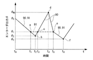
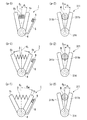
図4は、本発明の実施形態のマニピュレータシステムの動作の一例を説明する模式的なグラフである。横軸は時間t、縦軸はエンコーダ出力θである。図5は、本発明の実施形態のマニピュレータシステムの動作説明図である。図6は、本発明の実施形態のマニピュレータシステムの図5に続く動作説明図である。ただし、図5、6において(a−1)、(a−2)、(a−3)はマスタ操作部の動作を、(b−1)、(b−2)、(b−3)はこれに対応する開閉部311の動作を示す。図7(a)、(b)、(c)は、本発明の実施形態のマニピュレータシステムの表示場面の一例を示す模式図である。
Next, the operation of the master /
FIG. 4 is a schematic graph for explaining an example of the operation of the manipulator system according to the embodiment of the present invention. The horizontal axis is time t, and the vertical axis is the encoder output θ. FIG. 5 is an operation explanatory diagram of the manipulator system according to the embodiment of the present invention. FIG. 6 is an operation explanatory diagram subsequent to FIG. 5 of the manipulator system according to the embodiment of the present invention. However, in FIGS. 5 and 6, (a-1), (a-2), and (a-3) indicate the operation of the master operation unit, and (b-1), (b-2), and (b-3) indicate The operation of the opening /
まず、マスタスレーブマニピュレータ500の正常時の動作について、簡単に説明する。
マスタスレーブマニピュレータ500によれば、図1に示すように、マスタグリップ203L、203Rを把持した操作者Opが、表示部201を見ながら、マスタグリップ203L、203Rの位置または姿勢を変化させる操作を行うことができる。これに伴って、マスタアーム202の各可動部からのエンコーダの出力信号が、マスタ制御部401に送出される。
マスタ制御部401は、これらの出力信号を解析して、マスタグリップ203L、203Rのそれぞれの位置および姿勢に対応してスレーブマニピュレータ300を駆動するためのスレーブアーム301の各可動部の駆動指令値403を生成し、マニピュレータ制御部402に送出する。
マニピュレータ制御部402は、送出された駆動指令値403を、スレーブアーム301の駆動信号に変換して、スレーブ制御部303に送出する。これにより、スレーブアーム301が駆動制御されて、処置具302の先端の位置および姿勢が、マスタグリップ203L、203Rのそれぞれの位置および姿勢に対応して制御される。
First, a normal operation of the master /
According to the master /
The
The
一方、これと並行して、操作者Opは、必要に応じて、マスタグリップ203L、203Rの操作ハンドル1bを操作して、その開閉角を変える。このとき、マスタグリップ203L、203Rには、ばね3が設けられているため、操作ハンドル1bを閉じるとばね3が変形し、変形量に応じて弾性復元力が発生する。このため、操作ハンドル1bを操作する操作者Opの手に操作抵抗が感じられる。
このような操作ハンドル1bの操作により、マスタグリップ203L、203Rの各エンコーダ4の出力信号4aがマスタ制御部401に送出される。
マスタ制御部401は、この各エンコーダ4からの出力信号4aに基づいて、処置具302の先端に設けられた開閉部311の開閉を行う可動部である開閉駆動部313の駆動信号に対応する開閉指令値403Aを生成し、開閉駆動部313に対応する可動部選択信号404とともに、スレーブ制御部303に送出する。これにより、開閉駆動部313が駆動制御されて、処置具302の開閉部311の開閉角が、各操作ハンドル1bの開閉角に対応して制御される。
このため、開閉部311は被把持物を把持したり把持解除したりすることが可能となる。
On the other hand, in parallel with this, the operator Op operates the operation handles 1b of the master grips 203L and 203R to change the opening and closing angles as necessary. At this time, since the master grips 203L and 203R are provided with the
By such operation of the
Based on the
For this reason, the opening /
このようにして、操作者Opは、マスタ入力部200を通して、スレーブマニピュレータ300を遠隔操作して外科手術を行うことができる。
In this way, the operator Op can perform a surgical operation by remotely operating the
次に、開閉部311の開閉動作がマスタグリップ203L、203Rに基づいて適正に制御できなくなった場合に動作ついて説明する。
マスタグリップ203L、203Rは、いずれもマスタグリップ1からなるため、以下では、マスタグリップ1と開閉部311との関係を説明する。
また、簡単のため、操作ハンドル1bの開閉角θMと開閉部311の開閉角θSとが同一角度となる対応関係の制御を行う場合の例で説明する。
エンコーダ4、314の出力信号4a、314aは、開閉角の大きさを表すものとする。すなわち、エンコーダ4、314のエンコーダ出力θは、操作ハンドル1b、開閉部311の開閉角がθになっていることを示すものとする。
Next, the operation when the opening / closing operation of the opening /
Since the master grips 203L and 203R are both composed of the
Also, for simplicity, it is described in example where the opening and closing angle theta M of the
Assume that the
開閉部311の開閉動作が、マスタグリップ1の開閉動作と連動しなくなる原因は種々考えられるが、操作入力とずれた動作を続けると正確な開閉が行われず、開閉部311を用いた作業に支障が生じる。このため、マスタ制御部401は、開閉部311の開閉動作を常時監視して、許容値以上に開閉角がずれると、制御信号405によって、連動停止モードに切り換える。
このような状況は、特に、被把持物を把持したときに発生することが多い。例えば、操作者Opは、遠隔操作を行っているため、被把持物の大きさや硬さについて十分な情報を有している訳ではない。例えば、被把持物が十分硬いにも関わらず被把持物の大きさよりも開閉角を閉じてしまうと、開閉部311は開閉指令値403Aに対応する開閉角に閉じることができなくなり、操作ハンドル1bの開閉角と開閉部311の開閉角が相違してしまう。また、被把持物が変形可能であっても抵抗が大きかったり、閉じ速度が速すぎたりすると、やはり開閉部311は開閉指令値403Aに対応する開閉角に閉じることができない。
There are various reasons why the opening / closing operation of the opening /
Such a situation often occurs particularly when an object to be grasped is grasped. For example, since the operator Op performs a remote operation, the operator Op does not have sufficient information on the size and hardness of the object to be grasped. For example, if the opening / closing angle is closed more than the size of the object to be grasped even though the object to be grasped is sufficiently hard, the opening /
時刻t0(以下、時刻tnの添字nは、時間的な順序を示し、添字が大きい方が時間的に後であることを表す。)において操作ハンドル1bおよび開閉部311の開閉角がθ0(ただし、θ0<θMA)に開いている状態から、操作ハンドル1bを閉じて、図5(a−2)に示すような柔軟性を有する被把持物W(図5(a−2)参照)を把持するものとする。
このとき、エンコーダ4、314のエンコーダ出力θは、図4に示すように、時間とともに、折れ線90、91のように、θ0から減少していく。ここで、操作ハンドル1bと開閉部311とは連動状態にあるため、折れ線90、91は重なっている。
なお、エンコーダ出力の変化を折れ線で表しているのは一例であり、操作ハンドル1bの操作の仕方によっては、適宜の曲線状の変化を示す操作入力を行うことが可能である。
At the time t 0 (hereinafter, the subscript n of the time t n indicates the temporal order, and the larger subscript indicates the later in time), the opening / closing angles of the
At this time, the encoder output θ of the
It should be noted that the change in the encoder output is represented by a polygonal line, and an operation input indicating an appropriate curved change can be performed depending on how the
図4に示すように、時刻t1において、例えば、開閉部311が被把持物Wを把持した状態で、操作入力に合わせて閉じることができなくなった(θ=θ1、ただし、θ1<θ0)ものとする(図5(a−1)、(a−2)参照)。
この場合、図4の点aで折れ線90、91に分岐する時刻t1以後は、エンコーダ4のエンコーダ出力θは折れ線90のように低下するのに対して、エンコーダ314のエンコーダ出力θは、折れ線91(図示太破線参照)のように、θ=θ1のままである。
マスタ制御部401は、時刻t1の直後に、開閉角が許容値以上ずれていることを検出すると、制御信号405をマニピュレータ制御部402に送出して、連動停止モードに切り換える。これにより、操作者Opが操作ハンドル1bをさらに開閉しても、これに対応する開閉指令値403Aは、マニピュレータ制御部402からスレーブ制御部303に送出されることはない。
このため、開閉駆動部313は、連動停止モートに入った際の開閉角のままで停止する。
As shown in FIG. 4, at time t 1 , for example, in a state where the opening /
In this case, the encoder output θ of the encoder 4 decreases as shown by the
When the
For this reason, the opening /
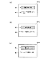
また、マスタ制御部401は、連動停止モードに切り換えると、図7(a)に示すように、表示部201の表示画面201aに連動障害が発生したことを知らせる警告表示M1(例えば「連動障害発生」)と、操作者Opの対処方法を説明するガイダンス表示M2(例えば「グリップを全開にしてください」)とを表示させる。
When the
操作者Opがガイダンス表示M2を見て、図4に示すように、時刻t2から操作ハンドル1bを開いていくと(図5(b−1)参照)、エンコーダ4のエンコーダ出力θは、θ2(ただし、θ2<θ1)からθMAに向かって増大していく。
その際、時刻t3において、エンコーダ4のエンコーダ出力がθ1(点c参照)となって、エンコーダ314のエンコーダ出力と一致する状態になる。
このとき、位置検出スイッチ6は操作ハンドル1bを検知しておらず、連動許可モード信号6aは未発生であるため、連動許可モードになっていない。また、マスタ制御部401は、出力信号4aの変化から、操作ハンドル1bの開閉角が開き方向に変化していることを検出している。
このため、本実施形態では、マスタ制御部401は、連動モードに切り換えず、エンコーダ4のエンコーダ出力が増大しても、開閉部311は連動せず、エンコーダ314のエンコーダ出力はθ=θ1のままである。すなわち、開閉部311は操作ハンドル1bの操作入力によって開かれることはない(図5(a−2)参照)。
Operator Op watches guidance display M2, (see FIG. 5 (b-1)) as shown in FIG. 4, when the time t 2 will open the
At this time, at time t 3 , the encoder output of the encoder 4 becomes θ 1 (see point c), and is in a state that matches the encoder output of the
At this time, the
For this reason, in this embodiment, the
時刻t4になると、操作者Opは操作ハンドル1bを最大の開閉角まで開く(図4の点d参照)。このとき、図5(c−1)に示すように、一方の操作ハンドル1bが、位置検出スイッチ6の位置検出位置に位置するため、位置検出スイッチ6は、連動許可モード信号6aをマスタ制御部401に送出する。これにより、連動許可モードが開始される。
マスタ制御部401は、図7(b)に示すように、連動許可モードに入り、連動障害を解消することが可能になったことを操作者Opに知らせるため、表示部201の表示画面201aに情報表示M3(例えば「連動準備」)と、操作者Opの対処方法を説明するガイダンス表示M4(例えば「グリップを閉じてください」)とを表示させる。
At time t 4, the operator Op
As shown in FIG. 7B, the
操作者Opは、表示部201に図7(b)の表示によって、これからの操作によって連動が開始されることが分かるため、連動開始した際の操作について予め準備しておくことができる。
操作者Opは、ガイダンス表示M4を見て、操作ハンドル1bを閉じていく。これにより、エンコーダ4のエンコーダ出力θは、θMAからθ1に向かって減少していく。
その際、時刻t5において、エンコーダ4のエンコーダ出力がθ1(点e参照)となって、エンコーダ314のエンコーダ出力と一致する(図6(a−1)、(a−2)参照)。
このとき、連動許可モードになっており、マスタ制御部401は、出力信号4aの変化から、操作ハンドル1bの開閉角が閉じ方向に変化していることを検出している。
このため、マスタ制御部401は、マニピュレータ制御部402に制御信号405を送出して、連動停止モードを連動モードに切り換える。
また、マスタ制御部401は、図7(c)に示すように、連動モードに入り、連動障害が解消されたことを操作者Opに知らせるために、表示部201に情報表示M5(例えば「連動OK」)と、詳細情報表示M6(例えば「スレーブは連動します」)とを表示させる。
The operator Op can know in advance that the interlocking will be started by the operation from now on, as shown in FIG. 7B on the
The operator Op looks at the guidance display M4 and closes the
At this time At time t 5, the encoder output of the encoder 4 becomes a theta 1 (refer to point e), the match with the encoder output of the encoder 314 (FIG. 6 (a-1), ( a-2) see).
At this time, the interlocking permission mode is set, and the
For this reason, the
Further, as shown in FIG. 7C, the
これにより、開閉部311の連動が再開され、以後、開閉部311の開閉角が操作ハンドル1bの開閉角と同様に変化する。
そこで、操作者Opは、時刻t1から行う予定であった操作、例えば、被把持物Wをさらに強く把持するように閉じる、といった操作を継続することができる(図6(b−1)、(b−2)、図4の直線ef参照)。
また、必要に応じて、操作ハンドル1bを開いて、被把持物Wの把持解除を行うことも可能である(図6(c−1)、(c−2)参照)。この場合、操作者Opは連動が再開されたことを了解した上で、操作ハンドル1bを開いていくため、被把持物Wが突然落下したりすることがないように、開く速さを調整したり、マスタグリップ1を移動してマスタアーム202を操作し、例えば、把持解除を行うのが適切な場所に開閉部311を移動した後に把持解除を行う、といった対処が可能となる。
Thereby, the interlocking of the opening /
Therefore, the operator Op the operation was scheduled to perform from time t 1, for example, close to grip further strongly object to be grasped W, such can continue the operation (FIG. 6 (b-1), (See b-2), straight line ef in FIG. 4).
Further, if necessary, the
このように、マスタスレーブマニピュレータ500によれば、操作者Opが操作可能な連動許可入力部として、位置検出スイッチ6を備えるため、予期しないタイミングで連動動作が起こることを防止できる。このため、開閉部311の動作がマスタグリップ1の操作入力に応じた動作からずれた場合に、開閉部311による作業性を向上することができる。
Thus, according to the master-
[第1変形例]
次に、本実施形態の第1変形例について説明する。
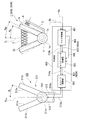
図8は、本発明の実施形態の第1変形例のマニピュレータシステムのマスタ操作部を示す模式的な断面図である。
[First Modification]
Next, a first modification of the present embodiment will be described.
FIG. 8 is a schematic cross-sectional view showing a master operation unit of a manipulator system according to a first modification of the embodiment of the present invention.
上記実施形態のマスタグリップ1が、位置検出スイッチ6により操作ハンドル1bの位置検出を行うことで連動許可モード信号6aを発生する構成であるのに対して、図8に示す本変形例のマスタグリップ10(マスタ操作部)は、操作ハンドル1bと連動して直動する部材(後述の移動軸13a)の位置を検出するものであり、位置検出スイッチ6はグリップ部1aに内蔵されている。
本変形例のマスタグリップ10は、上記実施形態のマスタグリップ1と同様に、マスタスレーブマニピュレータ500におけるマスタグリップ203L、203Rとして使用することが可能である。
以下、上記実施形態と異なる点を中心に説明する。
The
The
Hereinafter, a description will be given focusing on differences from the above embodiment.
本変形例のマスタグリップ10は、上記実施形態のマスタグリップ1の回動支軸1c、ばね3、エンコーダ4に代えて、回動支軸10c、アクチュエータ13、エンコーダ14(マスタ角度検出部)を備える。
The
回動支軸10cは、上記実施形態の回動支軸1cに代えて、操作ハンドル1bの一端部を回動可能に支持するものである。回動支軸10cは、グリップ部1aの内部において開閉中心軸線O1を挟み、開閉中心軸線O1に関して対称な2位置に配置され、この2位置で各操作ハンドル1bの一端部をそれぞれ支持している。
The
アクチュエータ13は、各操作ハンドル1bを開閉中心軸線O1に関して対称に開閉動作できるようにするとともに、操作ハンドル1bの操作に伴って操作抵抗を発生させるためのものである。
アクチュエータ13の概略構成は、開閉中心軸線O1に沿って直動移動する移動軸13aと、移動軸13aの一端部を移動可能に支持するとともに移動方向と逆方向に抵抗力を発生させる抵抗発生部13bとを備える。
The
A schematic configuration of the
移動軸13aの他端部は、筐体部1dの基端側(グリップ部1aに近い側)の内部に設けられたスライドガイド10dによって直動移動可能に支持されている。
移動軸13aの他端部における先端13cは、スライドガイド10dから筐体部1dの基端側に向いて突出されている。
また、移動軸13aの中間部と、各操作ハンドル1bとの間には、回動支軸10c回りの各操作ハンドル1bの回動運動を移動軸13aに伝達して移動軸13aを直動運動させるリンク10eが連結されている。これにより、操作ハンドル1bの開閉角と、移動軸13aとの移動量とは、一対一の関係にあり、移動軸13aの移動量から操作ハンドル1bの開閉角を検出することができる。
The other end portion of the moving
A
Further, between the intermediate portion of the
グリップ部1aにおいて、移動軸13aの先端13cの前方には、先端13cの移動範囲よりも離れた位置には、位置検出スイッチ6を配置するための支持板10aが設けられている。
支持板10a上の位置検出スイッチ6は、移動軸13aの先端13cの位置検出を行い、操作ハンドル1bの最大の開閉角に対応する位置に先端13cが到達したかどうかを検知することができる位置に配置されている。
In the
The
抵抗発生部13bは、移動軸13aの移動に抗する弾性部材、例えば、スプリングなどのばね部材、空気ばねなどを備え、筐体部1dの先端側(グリップ部1aと反対側)の内部に固定されている。
The
エンコーダ14は、アクチュエータ13の移動軸13aの移動量を検出して、この検出値の出力信号14aをマスタ制御部401に送出するものであり、図示略の配線により、マスタ制御部401と電気的に接続されている。
マスタ制御部401に送出された出力信号14aは、マスタ制御部401に予め記憶された変換テーブルなどにより、操作ハンドル1bの開閉角に換算される。
The
The
本変形例のマスタグリップ10によれば、上記実施形態のマスタグリップ1と同様に、操作ハンドル1bを最大の開閉角に開く操作者Opの操作により、位置検出スイッチ6から、マスタ制御部401に連動許可モード信号6aを送出することができる。
したがって、上記実施形態と同様にして、予期しないタイミングで連動動作が起こることを防止できるため、開閉部311の動作がマスタグリップ10の操作入力に応じた動作からずれた場合に、開閉部311による作業性を向上することができる。
According to the
Therefore, in the same manner as in the above embodiment, the interlocking operation can be prevented from occurring at an unexpected timing. Therefore, when the operation of the opening /
[第2変形例]
次に、本実施形態の第2変形例について説明する。
図9は、本発明の実施形態の第2変形例のマニピュレータシステムの主要部を示す模式的な構成図である。
[Second Modification]
Next, a second modification of the present embodiment will be described.
FIG. 9 is a schematic configuration diagram illustrating a main part of a manipulator system according to a second modification of the embodiment of the present invention.
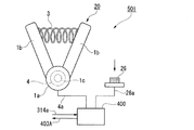
図9に示すように、本変形例のマスタスレーブマニピュレータ501(マニピュレータシステム)は、上記実施形態のマスタスレーブマニピュレータ500のマスタグリップ1に代えて、マスタグリップ20を備え、入力スイッチ26(連動許可入力部)を追加したものである。
以下、上記実施形態と異なる点を中心に説明する。
As shown in FIG. 9, a master slave manipulator 501 (manipulator system) of this modification includes a
Hereinafter, a description will be given focusing on differences from the above embodiment.
本変形例のマスタグリップ20は、上記実施形態のマスタグリップ1の支持アーム部材5、位置検出スイッチ6を削除したものである。
The
入力スイッチ26は、マスタグリップ20と別体に設けられ、操作者Opが適宜のタイミングで操作することにより、連動許可モードに入るための連動許可モード信号26aを発生させ、この連動許可モード信号26aをマスタ制御部401に送出するものである。このため、入力スイッチ26は、マスタ制御部401と電気的に接続されている。
入力スイッチ26の構成は、操作者Opが操作可能な入力スイッチであれば、特に限定されない。例えば、操作者Opが手で操作することができる押しボタンスイッチや、操作者Opが足で操作することができるフットスイッチなどを好適に採用することができる。
The
The configuration of the
本変形例のマスタスレーブマニピュレータ501によれば、連動許可モード信号26aを、操作者Opの操作により適宜のタイミングで発生させることができるため、マスタ制御部401が連動障害を検出すると、上記実施形態と同様にして、連動停止モードに切り換えるとともに、図7(a)におけるガイダンス表示M2に代えて、例えば「連動を再開する準備ができたら、入力スイッチを操作してください」のように、操作者Opが入力スイッチ26を操作することを促すメッセージを表示させる。
これにより、操作者Opは、警告表示M1とこのようなガイダンス表示によって連動障害が発生したことが理解されるため、操作者Opは、連動再開の準備をした上で、入力スイッチ26を操作し、連動許可モードに入ることができる。
According to the master-
Accordingly, the operator Op understands that the interlock failure has occurred due to the warning display M1 and such a guidance display. Therefore, the operator Op operates the
連動許可モードに入ると、マスタ制御部401は、図7(b)とほぼ同様な画面表示を行うが、ガイダンス表示M4は、例えば「グリップを障害発生時より開いてからゆっくり閉じてください」と言ったメッセージを表示させる。
これにより、操作者Opは、操作ハンドル1bを図4におけるエンコーダ出力θ1よりもわずかに開いて、点cを超えた適宜の開閉角から、操作ハンドル1bを閉じる操作を行うことができる。この操作により、閉じ方向において出力信号4aのエンコーダ出力がθ1に一致すると、上記実施形態と同様にして、マスタ制御部401によって連動停止モードから連動モードに切り換えられ、連動が再開される。
When the interlocking permission mode is entered, the
Thus, the operator Op is the
このようにして、本変形例では、操作者Opは、操作ハンドル1bの開閉角を最大の開閉角まで開くことなく、迅速に連動の修復を図ることができる。
また、連動障害発生時の開閉角からわずかに開いて閉じるだけで、連動を再開することができるため、連動障害発生時とほぼ同じ操作状態から連動を開始することができるため、開閉部311を用いた作業を、円滑に継続することができる。
特に、入力スイッチ26として、フットスイッチを採用すれば、操作者Opがマスタグリップ20からまったく手を離すことなく操作を行うことができるため、さらに円滑に作業を継続することできる。
In this way, in this modification, the operator Op can quickly repair the interlock without opening the opening / closing angle of the operation handle 1b to the maximum opening / closing angle.
Further, since the interlock can be resumed by simply opening and closing from the opening and closing angle when the interlock failure occurs, the interlock can be started from almost the same operation state as when the interlock failure occurs. The used work can be continued smoothly.
In particular, if a foot switch is employed as the
[第3変形例]
次に、本実施形態の第3変形例について説明する。
図10は、本発明の実施形態の第3変形例のマニピュレータシステムの主要部を示す模式的な断面図である。
[Third Modification]
Next, a third modification of the present embodiment will be described.
FIG. 10 is a schematic cross-sectional view showing a main part of a manipulator system according to a third modification of the embodiment of the present invention.
図10に示すように、本変形例のマスタスレーブマニピュレータ502(マニピュレータシステム)は、上記実施形態のマスタスレーブマニピュレータ500のマスタグリップ1に代えて、マスタグリップ30を備える。
以下、上記実施形態と異なる点を中心に説明する。
As shown in FIG. 10, the master-slave manipulator 502 (manipulator system) of this modification includes a
Hereinafter, a description will be given focusing on differences from the above embodiment.
本変形例のマスタグリップ30は、上記実施形態のマスタグリップ1の支持アーム部材5、位置検出スイッチ6を削除し、入力スイッチ36(連動許可入力部)を、筐体部1dの表面に配置したものである。すなわち、マスタグリップ30は、上記第2変形例のマスタグリップ20に入力スイッチ36を追加した構成になっている。
In the
入力スイッチ36は、操作者Opが適宜のタイミングで操作することにより、連動許可モードに入るため、上記第2変形例と同様の連動許可モード信号26aを発生させ、この連動許可モード信号26aをマスタ制御部401(図10では図示略)に送出するものである。このため、入力スイッチ36は、マスタ制御部401と電気的に接続されている。
入力スイッチ36の配置は、筐体部1dの表面であって、操作者Opが操作可能な位置であればどこでもよいが、本変形例では、操作者Opが操作入力を行うためにグリップ部1aを把持して状態で、いずれかの指で、操作できる位置に設けることが好ましい。
好ましい配置の一例としては、図10に示すように、グリップ部1aを握ったときに、上側となる、筐体部1dの上面1eを挙げることができる。この場合、例えば、操作者Opの人差し指を上方に移動させることで、入力スイッチ36を操作することが可能となる。このとき、他方の操作ハンドル1bは、操作者Opの親指で操作することが可能であり、人差し指を離しても、操作ハンドル1bの開閉角は、連動障害発生時と同じ角度に保つことができる。
The
The
As an example of a preferable arrangement, as shown in FIG. 10, an
入力スイッチ36の構成は、操作者Opが操作可能な入力スイッチであれば、特に限定されない。例えば、操作者Opが手で操作することができる押しボタンスイッチを好適に採用することができる。
The configuration of the
本変形例のマスタスレーブマニピュレータ502によれば、上記第2変形例のマスタスレーブマニピュレータ501と同様に、操作者Opが、操作ハンドル1bの開閉角を最大の開閉角まで開くことなく、迅速に連動の修復を図ることができ、連動障害発生時とほぼ同じ操作状態から連動を開始することができるため、開閉部311を用いた作業を、円滑に継続することができる。
特に、入力スイッチ36が筐体部1dの表面に設けられているため、グリップ部1aを把持した状態でも容易に入力スイッチ36を操作することができるため、さらに円滑に作業を継続することできる。
According to the master-
In particular, since the
[第4変形例]
次に、本実施形態の第4変形例について説明する。
図11は、本発明の実施形態の第4変形例のマニピュレータシステムのマスタ操作部を示す模式的な断面図である。
[Fourth Modification]
Next, a fourth modification of the present embodiment will be described.
FIG. 11 is a schematic cross-sectional view showing a master operation unit of a manipulator system according to a fourth modification of the embodiment of the present invention.
図11に示すように、本変形例のマスタグリップ40は、上記第1変形例のマスタグリップ10から位置検出スイッチ6を削除し、筐体部1dの側面1fに上記第3変形例の入力スイッチ36を配置したものである。
本変形例のマスタグリップ40は、上記実施形態のマスタグリップ1と同様に、マスタスレーブマニピュレータ500におけるマスタグリップ203L、203Rとして使用することが可能である。
以下、上記実施形態および上記第1変形例と異なる点を中心に説明する。
As shown in FIG. 11, in the
The
The following description will focus on differences from the embodiment and the first modification.
本変形例における入力スイッチ36の配置位置は、操作者Opがグリップ部1aを握ったとき、人差し指で操作する側の操作ハンドル1bが設けられた側面1fであって、操作ハンドル1bの先端よりもわずかに筐体部1dの先端側となる位置としている。
このため、操作者Opの人差し指を筐体部1dの先端側に移動させることで、入力スイッチ36を操作することが可能となる。このとき、本変形例においても、他方の操作ハンドル1bは、操作者Opの親指で操作することが可能であり、人差し指を離しても、操作ハンドル1bの開閉角は、連動障害発生時と同じ角度に保つことができる。
The arrangement position of the
For this reason, it becomes possible to operate the
本変形例のマスタグリップ40によれば、操作者Opが、操作ハンドル1bの開閉角を最大の開閉角まで開くことなく、迅速に連動の修復を図ることができ、連動障害発生時とほぼ同じ操作状態から連動を開始することができるため、上記第3変形例と同様に、開閉部311を用いた作業を、円滑に継続することができる。
According to the
なお、上記実施形態および各変形例の説明では、マスタ操作部がスレーブ動作部の開閉操作を行う場合の例で説明したが、マスタ操作部の操作入力は、開閉操作には限定されない。例えば、スレーブ動作部が直動動作を行って対象物を押圧するような場合に、直動動作の操作入力を行う構成としてもよい。 In the description of the above embodiment and each modification, an example in which the master operation unit performs an opening / closing operation of the slave operation unit has been described, but the operation input of the master operation unit is not limited to the opening / closing operation. For example, when the slave operation unit performs a linear motion operation and presses an object, the operation input of the linear motion operation may be performed.
また、上記の実施形態および各変形例の説明では、マスタ操作部がスレーブ動作部の開閉操作を行う場合に、開閉中心軸線に対して左右対称に開閉する場合の例で説明したが、適宜の軸線に対して非対称に開閉してもよい。また、一対の操作部材、または一対の処置具片の一方に対して他方のみが移動して開閉動作するようにしてもよい。 Further, in the above description of the embodiment and each modification example, when the master operation unit performs the opening / closing operation of the slave operation unit, the example in the case of opening / closing symmetrically with respect to the opening / closing center axis line has been described. You may open and close asymmetrically with respect to an axis. In addition, only the other of the pair of operation members or the pair of treatment instrument pieces may move to open and close.
また、上記実施形態および各変形例の説明では、連動制御部は、連動許可モード信号の受信後であって、操作部材の開閉角の検出値と開閉動作部の開閉角の検出値とが対応したとき、かつ操作部材の開閉角の検出値が操作部材の閉じ方向に変化している場合に、スレーブ動作部を操作入力に応じた動作に連動させる場合の例で説明した。
このような構成とすれば、連動が再開されたとき、操作部材が閉じる方向に移動しているため、誤って被把持物を落としたりすることがない。
ただし、連動許可モードは、操作者Opの操作によって連動許可入力部で発生する連動許可モード信号によって開始されるため、操作者Opは連動再開のタイミングを予期することができ、連動再開時の操作入力を準備できる状態にある。このため、連動を予期できず、連動再開の準備もできない場合に比べると、開閉部311が連動開始後に開いて行く場合にも、誤って把持物を落としたりするおそれは格段に少ない。
したがって、連動制御部は、連動許可モード信号の受信後であって、操作部材の開閉角の検出値と開閉動作部の開閉角の検出値とが対応したとき、かつ操作部材の開閉角の検出値が操作部材の開く方向に変化している場合に、スレーブ動作部を操作入力に応じた動作に連動させるようにすることが可能である。
この場合、連動再開直後は、開閉部311が開く方向に移動するため、被把持物に押圧力を作用しない。したがって、被把持物の変形を防止することができる。
In the description of the above embodiment and each modification, the interlock control unit corresponds to the detected value of the opening / closing angle of the operating member and the detected value of the opening / closing angle of the opening / closing operation unit after receiving the interlocking permission mode signal. In the case where the detected value of the opening / closing angle of the operation member is changed in the closing direction of the operation member, the slave operation unit is linked with the operation according to the operation input.
With such a configuration, when the interlocking is resumed, the operation member moves in the closing direction, so that the object to be grasped is not accidentally dropped.
However, since the interlock permission mode is started by the interlock permission mode signal generated at the interlock permission input unit by the operation of the operator Op, the operator Op can expect the timing of the interlock resumption, and the operation at the time of the interlock resumption Ready for input. For this reason, compared to the case where the interlocking cannot be anticipated and the preparation of the interlocking restart cannot be performed, the possibility that the grasped object is accidentally dropped even when the opening /
Therefore, the interlock control unit detects the open / close angle of the operation member when the detection value of the open / close angle of the operation member corresponds to the detection value of the open / close angle of the open / close operation unit after receiving the interlock permission mode signal. When the value changes in the opening direction of the operation member, the slave operation unit can be interlocked with the operation corresponding to the operation input.
In this case, immediately after resuming the interlock, the opening /
また、連動制御部は、連動許可モード信号の受信後であって、操作部材の開閉角の検出値と開閉動作部の開閉角の検出値とが対応したとき、かつ操作部材の開閉角の検出値が操作部材の開き方向または閉じ方向に変化している場合に、スレーブ動作部を操作入力に応じた動作に連動させることが可能であり、開き方向に変化している場合に連動させるか、閉じ方向に変化している場合に連動させるかを選択可能である構成とすることも可能である。
この場合、作業開始前に、操作者Opが、被把持物の種類や特性に合わせて、連動開始条件を、操作部材の開き方向とするか、閉じ方向とするか選択することができるため、被把持物の種類や特性に合わせて連動を再開させることができるため、連動障害が発生した場合でも、作業性を向上することができる。
The interlock control unit detects the opening / closing angle of the operation member when the detection value of the opening / closing angle of the operation member corresponds to the detection value of the opening / closing angle of the opening / closing operation unit after receiving the interlock permission mode signal. When the value is changing in the opening direction or closing direction of the operation member, the slave operation unit can be linked to the operation according to the operation input, and if the value is changing in the opening direction, It is also possible to adopt a configuration in which it is possible to select whether to interlock when changing in the closing direction.
In this case, before the work starts, the operator Op can select whether the interlock start condition is the opening direction or the closing direction of the operation member in accordance with the type and characteristics of the object to be grasped. Since interlocking can be resumed in accordance with the type and characteristics of the object to be grasped, workability can be improved even when an interlock failure occurs.
また、上記の実施形態および各変形例の説明では、マスタ制御部401が、表示部201に表示を行うことで、操作者Opに、連動障害の発生、連動許可モードへの移行、連動再開などを通知する場合の例で説明したが、音や音声で通知する構成とすることも可能である。
Further, in the description of the above-described embodiment and each modified example, the
また、上記の実施形態および各変形例の説明では、ばね3が自然状態のときに操作部材は最大開閉角に開いておらず、自然状態からさらに延ばされたときに位置検出スイッチ6を押圧する構成の場合の例で説明したが、ばね3の設置形態はこのような形態には限定されない。
例えば、ばね3が自然状態のときにちょうど最大開閉角に開くとともに、位置検出スイッチ6に押圧される構成とすることが可能である。
また、図12(a)、(b)に示す構成も可能である。図12(a)、(b)は、本発明の実施形態および各変形例に適用可能なばねの変形例(第5変形例)を示すマスタ操作部を示す模式的な構成図である。
この変形例(第5変形例)のマスタグリップ1A(マスタ操作部)は、上記実施形態のマスタグリップ1のばね3に代えてばね3Aを備える。ばね3Aの一端部(図示右側)は一方(図示右側)の操作ハンドル1bの内側に固定され、他端部(図示左側)は他方の操作ハンドル1bと接離可能に対向されている。
これにより、図12(b)に示すように、操作ハンドル1bが、ばね3Aが自然状態の長さ以下となる開閉角まで閉じられると、ばね3Aの弾性復元力が発生して操作抵抗が生じる。また、図12(a)に示すように、操作ハンドル1bが、ばね3Aの自然状態の長さ以上に間隔があく開閉角まで開かれると、ばね3Aによる操作抵抗は発生しない。
このような構成によれば、位置検出スイッチ6を押圧する際に、操作抵抗が発生しないため、軽い力で迅速に位置検出スイッチ6を押圧することができる。
Further, in the description of the above embodiment and each modification, when the
For example, when the
Moreover, the structure shown to Fig.12 (a), (b) is also possible. FIGS. 12A and 12B are schematic configuration diagrams showing a master operation unit showing a spring modification (fifth modification) applicable to the embodiment of the present invention and each modification.
A
Accordingly, as shown in FIG. 12B, when the
According to such a configuration, when the
また、上記の実施形態、および各変形例に説明したすべての構成要素は、本発明の技術的思想の範囲で適宜組み合わせを代えたり、削除したりして実施することができる。 In addition, all the components described in the above embodiment and each modification can be implemented by appropriately changing or deleting the combination within the scope of the technical idea of the present invention.
1、1A、10、20、30、40、203L、203R マスタグリップ(マスタ操作部)
1a グリップ部
1b 操作ハンドル(操作部材)
1d 筐体部
1e 上面(マスタ操作部の表面)
1f 側面(マスタ操作部の表面)
4、14 エンコーダ(マスタ角度検出部)
4a、14a、314a 出力信号
6 位置検出スイッチ(連動許可入力部)
6a、26a 連動許可モード信号
13 アクチュエータ
13a 移動軸
13b 抵抗発生部
26、36 入力スイッチ(連動許可入力部)
201 表示部(情報表示部)
300 スレーブマニピュレータ
311 開閉部(開閉動作部)
313 開閉駆動部
313a 駆動信号
314 エンコーダ(スレーブ角度検出部)
400 制御部(連動制御部)
401 マスタ制御部
402 マニピュレータ制御部
403 駆動指令値
403A 開閉指令値
405 制御信号
500、501、502 マスタスレーブマニピュレータ(マニピュレータシステム)
M1 警告表示
M2 ガイダンス表示
M3 情報表示
M4 ガイダンス表示
M5 情報表示
M6 詳細情報表示
Op 操作者
W 被把持物
1, 1A, 10, 20, 30, 40, 203L, 203R Master grip (master operation unit)
1f Side (surface of master operation unit)
4, 14 Encoder (Master angle detector)
4a, 14a,
6a, 26a Interlock
201 Display section (information display section)
300
313 Open /
400 Control unit (interlocking control unit)
401
M1 Warning display M2 Guidance display M3 Information display M4 Guidance display M5 Information display M6 Detailed information display Op Operator W Object to be gripped
Claims (6)
前記操作者が操作可能であり、操作されたときに、前記マスタ操作部の前記操作入力に基づく前記スレーブ動作部の連動を許可するモードに入る連動許可モード信号を前記連動制御部に送出する連動許可入力部を備え、
前記マスタ操作部は、
前記操作入力を行うため、開閉可能に設けられた操作部材と、
該操作部材の開閉角を検出し、前記操作部材の開閉角の検出値を前記連動制御部に送出するマスタ角度検出部と、
を備え、
前記スレーブ動作部は、
開閉可能に設けられた開閉動作部と、
該開閉動作部の開閉角を検出し、前記開閉動作部の開閉角の検出値を前記連動制御部に送出するスレーブ角度検出部と、
を備え、
前記連動許可入力部は、
前記操作部材が最大限開く位置に移動したことを検出して、前記連動許可モード信号を発生する位置検出スイッチを備え、
前記連動制御部は、
前記スレーブ動作部の動作が前記操作入力に応じた動作からずれた場合に、連動制御を停止して、前記マスタ操作部の前記操作入力と前記スレーブ動作部の動作状態とを監視し、
前記位置検出スイッチが発生した前記連動許可モード信号を受信後であって、前記操作部材の開閉角の検出値と前記開閉動作部の開閉角の検出値とが対応したことによって前記操作入力が前記動作状態に合致したことを検知したとき、かつ前記操作部材の開閉角の検出値が前記操作部材の閉じ方向に変化している場合に、前記スレーブ動作部の動作を前記操作入力に応じた動作に連動させる
ことを特徴とするマニピュレータシステム。 A master operation unit for an operator to input an operation, a slave operation unit operable in response to the operation input, and a control for analyzing the operation input and operating the slave operation unit in conjunction with the operation input. A manipulator system having an interlock control unit to perform,
An interlock that sends an interlocking permission mode signal to the interlocking control unit that is operable by the operator and enters a mode that permits interlocking of the slave operating part based on the operation input of the master operating part when operated. With permission input,
The master operation unit
In order to perform the operation input, an operation member provided to be openable and closable,
A master angle detector that detects an opening / closing angle of the operation member and sends a detection value of the opening / closing angle of the operation member to the interlock control unit;
With
The slave operating unit is
An opening / closing operation unit provided to be openable and closable;
A slave angle detector that detects an open / close angle of the open / close operation unit and sends a detection value of the open / close angle of the open / close operation unit to the interlock control unit;
With
The interlock permission input unit
A position detection switch for detecting that the operating member has moved to the maximum opening position and generating the interlocking permission mode signal;
The interlock control unit
When the operation of the slave operation unit deviates from the operation corresponding to the operation input, stop the interlock control, and monitor the operation input of the master operation unit and the operation state of the slave operation unit,
After receiving the interlocking permission mode signal generated by the position detection switch, the operation input is determined by the correspondence between the detected value of the opening / closing angle of the operating member and the detected value of the opening / closing angle of the opening / closing operation unit. When it is detected that the operating state is matched , and the detected value of the opening / closing angle of the operating member is changed in the closing direction of the operating member, the operation of the slave operating unit is performed according to the operation input. Manipulator system characterized by being linked to
前記連動制御部は、
前記連動許可モード信号の受信後であって、前記スレーブ動作部が前記操作入力に応じた動作に連動したことを検出したとき、前記情報表示部に連動が再開されたことを表示させる
ことを特徴とする請求項1に記載のマニピュレータシステム。 An information display unit for displaying information sent from the interlock control unit;
The interlock control unit
After receiving the interlock permission mode signal, when detecting that the slave operation unit is interlocked with the operation according to the operation input, the information display unit displays that the interlock is resumed. The manipulator system according to claim 1 .
前記マスタ操作部の表面に設けられた入力スイッチからなる
ことを特徴とする請求項1に記載のマニピュレータシステム。 The interlock permission input unit
The manipulator system according to claim 1, comprising an input switch provided on a surface of the master operation unit.
前記マスタ操作部と別体に設けられた入力スイッチからなる
ことを特徴とする請求項1に記載のマニピュレータシステム。 The interlock permission input unit
The manipulator system according to claim 1 , comprising an input switch provided separately from the master operation unit.
フットスイッチからなる
ことを特徴とする請求項4に記載のマニピュレータシステム。 The input switch is
The manipulator system according to claim 4 , comprising a foot switch.
前記連動許可モード信号の受信後であって、前記操作部材の開閉角の検出値と前記開閉動作部の開閉角の検出値とが対応したとき、かつ前記操作部材の開閉角の検出値が前記操作部材の開き方向に変化している場合にも、前記スレーブ動作部を前記操作入力に応じた動作に連動させることが可能であり、
前記開き方向に変化している場合に連動させるか、前記閉じ方向に変化している場合に連動させるかを選択可能である
ことを特徴とする請求項1に記載のマニピュレータシステム。 Before Symbol interlocking control unit,
After the reception of the interlock permission mode signal, when the detected value of the opening / closing angle of the operating member corresponds to the detected value of the opening / closing angle of the opening / closing operation unit, and the detected value of the opening / closing angle of the operating member is when the opening direction of the operation member is changed even, it is possible to interlock the slave operation unit to the action according to the operation input,
2. The manipulator system according to claim 1, wherein it is possible to select whether to interlock when changing in the opening direction or interlocking when changing in the closing direction.
Priority Applications (5)
| Application Number | Priority Date | Filing Date | Title |
|---|---|---|---|
| JP2012116740A JP6000641B2 (en) | 2011-08-04 | 2012-05-22 | Manipulator system |
| PCT/JP2012/070417 WO2013018933A1 (en) | 2011-08-04 | 2012-08-03 | Manipulator system |
| EP12819398.4A EP2739230B1 (en) | 2011-08-04 | 2012-08-03 | Manipulator system |
| CN201280038298.4A CN103747759B (en) | 2011-08-04 | 2012-08-03 | Effector system |
| US14/169,321 US9244523B2 (en) | 2011-08-04 | 2014-01-31 | Manipulator system |
Applications Claiming Priority (4)
| Application Number | Priority Date | Filing Date | Title |
|---|---|---|---|
| US201161515203P | 2011-08-04 | 2011-08-04 | |
| US61/515,203 | 2011-08-04 | ||
| JP2012116740A JP6000641B2 (en) | 2011-08-04 | 2012-05-22 | Manipulator system |
| PCT/JP2012/070417 WO2013018933A1 (en) | 2011-08-04 | 2012-08-03 | Manipulator system |
Publications (2)
| Publication Number | Publication Date |
|---|---|
| JP2013034851A JP2013034851A (en) | 2013-02-21 |
| JP6000641B2 true JP6000641B2 (en) | 2016-10-05 |
Family
ID=47629436
Family Applications (1)
| Application Number | Title | Priority Date | Filing Date |
|---|---|---|---|
| JP2012116740A Active JP6000641B2 (en) | 2011-08-04 | 2012-05-22 | Manipulator system |
Country Status (5)
| Country | Link |
|---|---|
| US (1) | US9244523B2 (en) |
| EP (1) | EP2739230B1 (en) |
| JP (1) | JP6000641B2 (en) |
| CN (1) | CN103747759B (en) |
| WO (1) | WO2013018933A1 (en) |
Families Citing this family (37)
| Publication number | Priority date | Publication date | Assignee | Title |
|---|---|---|---|---|
| EP3459694B1 (en) * | 2012-02-15 | 2021-09-22 | Intuitive Surgical Operations, Inc. | User selection of robotic system operating modes using mode distinguishing operator actions |
| KR20140102465A (en) * | 2013-02-14 | 2014-08-22 | 삼성전자주식회사 | Surgical robot and method for controlling the same |
| US9387045B2 (en) * | 2013-05-14 | 2016-07-12 | Intuitive Surgical Operations, Inc. | Grip force normalization for surgical instrument |
| JP6296236B2 (en) * | 2013-05-27 | 2018-03-20 | パナソニックIpマネジメント株式会社 | Master device for master-slave device, control method therefor, and master-slave device |
| CN105611894B (en) | 2013-08-15 | 2019-02-15 | 直观外科手术操作公司 | Instrument sterile adaptor drives feature |
| CN105611892B (en) * | 2013-08-15 | 2019-02-19 | 直观外科手术操作公司 | Robotic tool driven element |
| CN108784838B (en) | 2013-08-15 | 2021-06-08 | 直观外科手术操作公司 | Instrument sterile adapter drive interface |
| KR102523090B1 (en) | 2013-08-15 | 2023-04-19 | 인튜어티브 서지컬 오퍼레이션즈 인코포레이티드 | Preloaded surgical instrument interface |
| US9283048B2 (en) * | 2013-10-04 | 2016-03-15 | KB Medical SA | Apparatus and systems for precise guidance of surgical tools |
| JP6358463B2 (en) * | 2013-11-13 | 2018-07-18 | パナソニックIpマネジメント株式会社 | Master device for master-slave device, control method therefor, and master-slave device |
| US10660717B2 (en) * | 2014-04-24 | 2020-05-26 | Covidien Lp | Robotic interface positioning determination systems and methods |
| JP2016016238A (en) * | 2014-07-10 | 2016-02-01 | オリンパス株式会社 | manipulator |
| WO2016125398A1 (en) | 2015-02-03 | 2016-08-11 | オリンパス株式会社 | Medical manipulator system and control method therefor |
| US9486927B1 (en) * | 2015-05-20 | 2016-11-08 | Google Inc. | Robotic gripper with multiple pairs of gripping fingers |
| WO2016194539A1 (en) * | 2015-05-29 | 2016-12-08 | オリンパス株式会社 | Medical manipulator system |
| WO2017031132A1 (en) | 2015-08-17 | 2017-02-23 | Intuitive Surgical Operations, Inc. | Unground master control devices and methods of use |
| JP2019500914A (en) * | 2015-10-22 | 2019-01-17 | コヴィディエン リミテッド パートナーシップ | Variable scanning for input devices |
| JP6959264B2 (en) * | 2016-06-03 | 2021-11-02 | コヴィディエン リミテッド パートナーシップ | Control arm assembly for robotic surgery system |
| GB2554363B (en) | 2016-09-21 | 2021-12-08 | Cmr Surgical Ltd | User interface device |
| WO2018109851A1 (en) | 2016-12-14 | 2018-06-21 | オリンパス株式会社 | Medical manipulator system |
| US11633246B2 (en) | 2016-12-15 | 2023-04-25 | Intuitive Surgical Operations, Inc. | Actuated grips for controller |
| US10251716B2 (en) | 2016-12-19 | 2019-04-09 | Ethicon Llc | Robotic surgical system with selective motion control decoupling |
| GB2560384B (en) * | 2017-03-10 | 2022-07-20 | Cmr Surgical Ltd | Controlling a surgical instrument |
| GB2606080B (en) * | 2017-03-10 | 2023-02-15 | Cmr Surgical Ltd | Controlling a surgical instrument |
| WO2018179323A1 (en) | 2017-03-31 | 2018-10-04 | オリンパス株式会社 | Manipulator |
| WO2019026654A1 (en) * | 2017-07-31 | 2019-02-07 | 株式会社メディカロイド | Master operation input device and master-slave manipulator |
| WO2019070734A1 (en) | 2017-10-02 | 2019-04-11 | Intuitive Surgical Operations, Inc. | End effector force feedback to master controller |
| US11712314B2 (en) | 2017-11-15 | 2023-08-01 | Intuitive Surgical Operations, Inc. | Master control device and methods therefor |
| CN110664583A (en) * | 2018-07-03 | 2020-01-10 | 中国科学院沈阳自动化研究所 | Eight-degree-of-freedom local force feedback bionic upper limb exoskeleton master hand |
| CN110666821B (en) * | 2018-07-03 | 2023-06-27 | 中国科学院沈阳自动化研究所 | Single-degree-of-freedom force feedback handle |
| WO2020042148A1 (en) * | 2018-08-31 | 2020-03-05 | 天津大学 | Magnetic navigation sensing-based main operating hand and system of minimally invasive surgical robot |
| CN111012513B (en) * | 2018-10-09 | 2021-07-27 | 成都博恩思医学机器人有限公司 | Surgical instrument control method of laparoscopic surgery robot |
| US11478312B2 (en) * | 2019-05-10 | 2022-10-25 | Verb Surgical Inc. | Unmatching/matching UID to robot grasper for engaging teleoperation |
| GB2590593B (en) | 2019-10-28 | 2023-09-13 | Cmr Surgical Ltd | Controlling a surgical instrument |
| GB2596543A (en) * | 2020-06-30 | 2022-01-05 | Cmr Surgical Ltd | Controlling a surgical instrument |
| WO2024003800A1 (en) * | 2022-06-29 | 2024-01-04 | Auris Health, Inc. | Safe mode and fire mode for robotic clip applier |
| US11844585B1 (en) * | 2023-02-10 | 2023-12-19 | Distalmotion Sa | Surgical robotics systems and devices having a sterile restart, and methods thereof |
Family Cites Families (212)
| Publication number | Priority date | Publication date | Assignee | Title |
|---|---|---|---|---|
| US3139990A (en) | 1961-12-11 | 1964-07-07 | Central Res Lab Inc | Rugged-duty master-slave manipulator |
| JPH0789293B2 (en) | 1986-07-23 | 1995-09-27 | 松下電器産業株式会社 | Arm control device |
| SE462645B (en) | 1987-03-31 | 1990-08-06 | Asea Ab | DEVICE FOR INDUSTRIAL ROBOTS WITH REGARD TO TOOLS |
| JPS6434688A (en) | 1987-07-29 | 1989-02-06 | Kubota Ltd | Master/slave manipulator |
| JPH0796182B2 (en) | 1988-03-16 | 1995-10-18 | ニッタ株式会社 | A device that eliminates the effects of the weight of the tool |
| JPH01271185A (en) * | 1988-04-20 | 1989-10-30 | Fujitsu Ltd | Remote robot manipulating system |
| JP3088004B2 (en) | 1989-04-28 | 2000-09-18 | 株式会社東芝 | Operation command device |
| JP2610956B2 (en) * | 1988-09-05 | 1997-05-14 | 株式会社日立製作所 | Master-slave manipulator |
| JPH0741560B2 (en) | 1989-11-16 | 1995-05-10 | 工業技術院長 | Master / slave robot control method |
| US5214969A (en) | 1991-02-19 | 1993-06-01 | Philip Morris Incorporated | Automatic testing of a plurality of smoking articles |
| JPH0596477A (en) * | 1991-10-03 | 1993-04-20 | Mitsubishi Heavy Ind Ltd | Control method for master and slave manipulators |
| US6963792B1 (en) | 1992-01-21 | 2005-11-08 | Sri International | Surgical method |
| US5631973A (en) | 1994-05-05 | 1997-05-20 | Sri International | Method for telemanipulation with telepresence |
| JPH05329784A (en) | 1992-05-28 | 1993-12-14 | Yaskawa Electric Corp | Control system for master slave robot |
| US5762458A (en) | 1996-02-20 | 1998-06-09 | Computer Motion, Inc. | Method and apparatus for performing minimally invasive cardiac procedures |
| JP2610094B2 (en) * | 1993-05-13 | 1997-05-14 | 株式会社明電舎 | Control device for industrial manipulator |
| US5656903A (en) | 1993-10-01 | 1997-08-12 | The Ohio State University Research Foundation | Master-slave position and motion control system |
| JP3339953B2 (en) | 1993-12-29 | 2002-10-28 | オリンパス光学工業株式会社 | Medical master-slave manipulator |
| JPH07241300A (en) | 1994-03-04 | 1995-09-19 | Olympus Optical Co Ltd | Holder of medical treatment appliance |
| JPH07246578A (en) | 1994-03-11 | 1995-09-26 | Yaskawa Electric Corp | Master hand device |
| DE4412605B4 (en) | 1994-04-13 | 2005-10-20 | Zeiss Carl | Method for operating a stereotactic adapter |
| JP2991403B2 (en) | 1994-08-29 | 1999-12-20 | 株式会社アイチコーポレーション | Manipulator gripper control device |
| US5836869A (en) | 1994-12-13 | 1998-11-17 | Olympus Optical Co., Ltd. | Image tracking endoscope system |
| US5632432A (en) | 1994-12-19 | 1997-05-27 | Ethicon Endo-Surgery, Inc. | Surgical instrument |
| US5603723A (en) | 1995-01-11 | 1997-02-18 | United States Surgical Corporation | Surgical instrument configured to be disassembled for cleaning |
| JPH08215204A (en) * | 1995-02-08 | 1996-08-27 | Olympus Optical Co Ltd | Medical manipulator |
| JPH08243080A (en) | 1995-03-07 | 1996-09-24 | Olympus Optical Co Ltd | Endoscope cleaning and disinfecting apparatus |
| US5649956A (en) | 1995-06-07 | 1997-07-22 | Sri International | System and method for releasably holding a surgical instrument |
| US5814038A (en) | 1995-06-07 | 1998-09-29 | Sri International | Surgical manipulator for a telerobotic system |
| US5871493A (en) | 1995-10-31 | 1999-02-16 | Smith & Nephew Endoscopy Inc. | Surgical instrument handpiece and system |
| US5712543A (en) | 1995-10-31 | 1998-01-27 | Smith & Nephew Endoscopy Inc. | Magnetic switching element for controlling a surgical device |
| US6699177B1 (en) | 1996-02-20 | 2004-03-02 | Computer Motion, Inc. | Method and apparatus for performing minimally invasive surgical procedures |
| US5855583A (en) | 1996-02-20 | 1999-01-05 | Computer Motion, Inc. | Method and apparatus for performing minimally invasive cardiac procedures |
| US6063095A (en) | 1996-02-20 | 2000-05-16 | Computer Motion, Inc. | Method and apparatus for performing minimally invasive surgical procedures |
| JP4176126B2 (en) | 1996-02-20 | 2008-11-05 | コンピュータ・モーション・インコーポレーテッド | Method and apparatus for performing cardiac surgery with minimal invasion |
| US6436107B1 (en) | 1996-02-20 | 2002-08-20 | Computer Motion, Inc. | Method and apparatus for performing minimally invasive surgical procedures |
| US5792135A (en) | 1996-05-20 | 1998-08-11 | Intuitive Surgical, Inc. | Articulated surgical instrument for performing minimally invasive surgery with enhanced dexterity and sensitivity |
| US6364888B1 (en) | 1996-09-09 | 2002-04-02 | Intuitive Surgical, Inc. | Alignment of master and slave in a minimally invasive surgical apparatus |
| JPH10128538A (en) | 1996-10-29 | 1998-05-19 | Hitachi Constr Mach Co Ltd | Welding robot and its sensor adapter |
| US6132441A (en) | 1996-11-22 | 2000-10-17 | Computer Motion, Inc. | Rigidly-linked articulating wrist with decoupled motion transmission |
| US6132368A (en) | 1996-12-12 | 2000-10-17 | Intuitive Surgical, Inc. | Multi-component telepresence system and method |
| US7666191B2 (en) | 1996-12-12 | 2010-02-23 | Intuitive Surgical, Inc. | Robotic surgical system with sterile surgical adaptor |
| US6331181B1 (en) | 1998-12-08 | 2001-12-18 | Intuitive Surgical, Inc. | Surgical robotic tools, data architecture, and use |
| US7699855B2 (en) | 1996-12-12 | 2010-04-20 | Intuitive Surgical Operations, Inc. | Sterile surgical adaptor |
| US8206406B2 (en) | 1996-12-12 | 2012-06-26 | Intuitive Surgical Operations, Inc. | Disposable sterile surgical adaptor |
| EP2362285B1 (en) | 1997-09-19 | 2015-03-25 | Massachusetts Institute of Technology | Robotic apparatus |
| US20080177285A1 (en) * | 1998-02-24 | 2008-07-24 | Hansen Medical, Inc. | Surgical instrument |
| JPH11300662A (en) | 1998-04-27 | 1999-11-02 | Yokogawa Electric Corp | Micropincette |
| JP4129313B2 (en) | 1998-05-19 | 2008-08-06 | オリンパス株式会社 | Medical system control device |
| WO2000007503A1 (en) | 1998-08-04 | 2000-02-17 | Intuitive Surgical, Inc. | Manipulator positioning linkage for robotic surgery |
| US8600551B2 (en) * | 1998-11-20 | 2013-12-03 | Intuitive Surgical Operations, Inc. | Medical robotic system with operatively couplable simulator unit for surgeon training |
| US6659939B2 (en) | 1998-11-20 | 2003-12-09 | Intuitive Surgical, Inc. | Cooperative minimally invasive telesurgical system |
| US6459926B1 (en) * | 1998-11-20 | 2002-10-01 | Intuitive Surgical, Inc. | Repositioning and reorientation of master/slave relationship in minimally invasive telesurgery |
| US6602185B1 (en) | 1999-02-18 | 2003-08-05 | Olympus Optical Co., Ltd. | Remote surgery support system |
| US6594552B1 (en) | 1999-04-07 | 2003-07-15 | Intuitive Surgical, Inc. | Grip strength with tactile feedback for robotic surgery |
| JP4354042B2 (en) | 1999-04-30 | 2009-10-28 | オリンパス株式会社 | Medical manipulator device |
| JP3608448B2 (en) | 1999-08-31 | 2005-01-12 | 株式会社日立製作所 | Treatment device |
| AU7651900A (en) | 1999-09-09 | 2001-04-10 | Tuebingen Scientific Surgical Products Ohg | Surgical instrument for minimally invasive surgical interventions |
| US7594912B2 (en) | 2004-09-30 | 2009-09-29 | Intuitive Surgical, Inc. | Offset remote center manipulator for robotic surgery |
| US8004229B2 (en) | 2005-05-19 | 2011-08-23 | Intuitive Surgical Operations, Inc. | Software center and highly configurable robotic systems for surgery and other uses |
| JP2001087281A (en) | 1999-09-20 | 2001-04-03 | Olympus Optical Co Ltd | Multifunctional manipulator |
| US6206903B1 (en) | 1999-10-08 | 2001-03-27 | Intuitive Surgical, Inc. | Surgical tool with mechanical advantage |
| JP3188953B2 (en) | 1999-10-13 | 2001-07-16 | 経済産業省産業技術総合研究所長 | Power assist device and control method thereof |
| US6666876B2 (en) | 2000-02-24 | 2003-12-23 | Hitachi, Ltd. | Forceps and manipulator with using thereof |
| JP2001309920A (en) | 2000-02-24 | 2001-11-06 | Hitachi Ltd | Forceps and manipulator using the same |
| JP3613551B2 (en) | 2000-03-31 | 2005-01-26 | 株式会社東芝 | Medical manipulator |
| US8888688B2 (en) | 2000-04-03 | 2014-11-18 | Intuitive Surgical Operations, Inc. | Connector device for a controllable instrument |
| JP4716545B2 (en) | 2000-06-28 | 2011-07-06 | オリンパス株式会社 | Surgical microscope equipment |
| US20010055062A1 (en) | 2000-04-20 | 2001-12-27 | Keiji Shioda | Operation microscope |
| US6645196B1 (en) | 2000-06-16 | 2003-11-11 | Intuitive Surgical, Inc. | Guided tool change |
| US6746443B1 (en) | 2000-07-27 | 2004-06-08 | Intuitive Surgical Inc. | Roll-pitch-roll surgical tool |
| JP2002059380A (en) | 2000-08-22 | 2002-02-26 | Olympus Optical Co Ltd | Master-slave device |
| JP4014792B2 (en) | 2000-09-29 | 2007-11-28 | 株式会社東芝 | manipulator |
| US6840938B1 (en) | 2000-12-29 | 2005-01-11 | Intuitive Surgical, Inc. | Bipolar cauterizing instrument |
| US7699835B2 (en) | 2001-02-15 | 2010-04-20 | Hansen Medical, Inc. | Robotically controlled surgical instruments |
| EP2298220B1 (en) | 2001-02-15 | 2016-06-08 | Hansen Medical, Inc. | Flexible instrument |
| US20030135204A1 (en) | 2001-02-15 | 2003-07-17 | Endo Via Medical, Inc. | Robotically controlled medical instrument with a flexible section |
| JP3660887B2 (en) | 2001-03-19 | 2005-06-15 | 株式会社日立製作所 | Surgery support device |
| US6994708B2 (en) | 2001-04-19 | 2006-02-07 | Intuitive Surgical | Robotic tool with monopolar electro-surgical scissors |
| US6783524B2 (en) | 2001-04-19 | 2004-08-31 | Intuitive Surgical, Inc. | Robotic surgical tool with ultrasound cauterizing and cutting instrument |
| US20040243147A1 (en) | 2001-07-03 | 2004-12-02 | Lipow Kenneth I. | Surgical robot and robotic controller |
| JP2003024336A (en) | 2001-07-16 | 2003-01-28 | Hitachi Ltd | Operation instrument |
| JP3926119B2 (en) * | 2001-08-10 | 2007-06-06 | 株式会社東芝 | Medical manipulator |
| US6676684B1 (en) | 2001-09-04 | 2004-01-13 | Intuitive Surgical, Inc. | Roll-pitch-roll-yaw surgical tool |
| JP4832679B2 (en) | 2001-09-11 | 2011-12-07 | オリンパス株式会社 | Microscope system |
| US6587750B2 (en) | 2001-09-25 | 2003-07-01 | Intuitive Surgical, Inc. | Removable infinite roll master grip handle and touch sensor for robotic surgery |
| US6839612B2 (en) | 2001-12-07 | 2005-01-04 | Institute Surgical, Inc. | Microwrist system for surgical procedures |
| JP4098535B2 (en) | 2002-02-28 | 2008-06-11 | オリンパス株式会社 | Medical stereoscopic display |
| JP3766805B2 (en) | 2002-03-15 | 2006-04-19 | 株式会社日立製作所 | Surgery support device |
| JP4073249B2 (en) | 2002-05-17 | 2008-04-09 | オリンパス株式会社 | Surgery system |
| JP3712693B2 (en) | 2002-05-21 | 2005-11-02 | 株式会社東芝 | Medical manipulator |
| US7331967B2 (en) | 2002-09-09 | 2008-02-19 | Hansen Medical, Inc. | Surgical instrument coupling mechanism |
| JP3680050B2 (en) | 2002-09-18 | 2005-08-10 | 株式会社東芝 | Medical manipulator and control method thereof |
| JP3912251B2 (en) | 2002-10-02 | 2007-05-09 | 株式会社日立製作所 | manipulator |
| US7443115B2 (en) | 2002-10-29 | 2008-10-28 | Matsushita Electric Industrial Co., Ltd. | Apparatus and method for robot handling control |
| JP3686947B2 (en) | 2002-12-09 | 2005-08-24 | 国立大学法人 東京大学 | High-rigid forceps tip structure for active forceps and active forceps including the same |
| JP3805310B2 (en) | 2003-01-30 | 2006-08-02 | ファナック株式会社 | Work take-out device |
| WO2004106009A1 (en) | 2003-06-02 | 2004-12-09 | Matsushita Electric Industrial Co., Ltd. | Article operating system and method, and article managing system and method |
| US7476237B2 (en) | 2003-02-27 | 2009-01-13 | Olympus Corporation | Surgical instrument |
| US7295893B2 (en) * | 2003-03-31 | 2007-11-13 | Kabushiki Kaisha Toshiba | Manipulator and its control apparatus and method |
| DE10324844A1 (en) | 2003-04-01 | 2004-12-23 | Tuebingen Scientific Surgical Products Gmbh | Surgical instrument with instrument handle and zero point adjustment |
| US20050033117A1 (en) | 2003-06-02 | 2005-02-10 | Olympus Corporation | Object observation system and method of controlling object observation system |
| US9002518B2 (en) * | 2003-06-30 | 2015-04-07 | Intuitive Surgical Operations, Inc. | Maximum torque driving of robotic surgical tools in robotic surgical systems |
| DE10357105B3 (en) | 2003-12-06 | 2005-04-07 | Richard Wolf Gmbh | Medical instrument for medical applications comprises an insert and a handle detachedly connected to each other |
| JP4472361B2 (en) | 2004-01-06 | 2010-06-02 | オリンパス株式会社 | Medical instrument holding device and medical instrument holding system. |
| JP2005261827A (en) | 2004-03-22 | 2005-09-29 | Olympus Corp | Treatment tool for endoscope |
| US7862579B2 (en) | 2004-07-28 | 2011-01-04 | Ethicon Endo-Surgery, Inc. | Electroactive polymer-based articulation mechanism for grasper |
| JP2006061272A (en) | 2004-08-25 | 2006-03-09 | Olympus Corp | Medical instrument holding device |
| US9261172B2 (en) | 2004-09-30 | 2016-02-16 | Intuitive Surgical Operations, Inc. | Multi-ply strap drive trains for surgical robotic arms |
| US20060087746A1 (en) | 2004-10-22 | 2006-04-27 | Kenneth Lipow | Remote augmented motor-sensory interface for surgery |
| JP2006167867A (en) | 2004-12-16 | 2006-06-29 | Fuji Heavy Ind Ltd | Remote control device |
| JP4528136B2 (en) | 2005-01-11 | 2010-08-18 | 株式会社日立製作所 | Surgical device |
| US7654431B2 (en) | 2005-02-18 | 2010-02-02 | Ethicon Endo-Surgery, Inc. | Surgical instrument with guided laterally moving articulation member |
| US7559450B2 (en) | 2005-02-18 | 2009-07-14 | Ethicon Endo-Surgery, Inc. | Surgical instrument incorporating a fluid transfer controlled articulation mechanism |
| US8496647B2 (en) | 2007-12-18 | 2013-07-30 | Intuitive Surgical Operations, Inc. | Ribbed force sensor |
| JP5160025B2 (en) | 2005-04-14 | 2013-03-13 | オリンパスメディカルシステムズ株式会社 | Surgery system |
| EP2992811B1 (en) | 2005-04-18 | 2018-03-07 | M.S.T. Medical Surgery Technologies Ltd. | Means and methods of improving laparoscopic surgery |
| US8073528B2 (en) | 2007-09-30 | 2011-12-06 | Intuitive Surgical Operations, Inc. | Tool tracking systems, methods and computer products for image guided surgery |
| US9492240B2 (en) | 2009-06-16 | 2016-11-15 | Intuitive Surgical Operations, Inc. | Virtual measurement tool for minimally invasive surgery |
| US8147503B2 (en) | 2007-09-30 | 2012-04-03 | Intuitive Surgical Operations Inc. | Methods of locating and tracking robotic instruments in robotic surgical systems |
| US8108072B2 (en) | 2007-09-30 | 2012-01-31 | Intuitive Surgical Operations, Inc. | Methods and systems for robotic instrument tool tracking with adaptive fusion of kinematics information and image information |
| JP2006321027A (en) | 2005-05-20 | 2006-11-30 | Hitachi Ltd | Master slave type manipulator system and its operation input device |
| US7717312B2 (en) | 2005-06-03 | 2010-05-18 | Tyco Healthcare Group Lp | Surgical instruments employing sensors |
| US8398541B2 (en) | 2006-06-06 | 2013-03-19 | Intuitive Surgical Operations, Inc. | Interactive user interfaces for robotic minimally invasive surgical systems |
| JP4488312B2 (en) | 2005-07-08 | 2010-06-23 | オリンパス株式会社 | Medical manipulator system |
| JP2007029274A (en) | 2005-07-25 | 2007-02-08 | Hitachi Ltd | Operation tool device |
| US7959050B2 (en) | 2005-07-26 | 2011-06-14 | Ethicon Endo-Surgery, Inc | Electrically self-powered surgical instrument with manual release |
| JP2007038315A (en) | 2005-08-01 | 2007-02-15 | Toyota Motor Corp | Operating device, operating adjustment method of operating element and program therefor |
| JP2007098507A (en) | 2005-10-04 | 2007-04-19 | Nagoya Institute Of Technology | Work assisting device |
| EP3155998B1 (en) | 2005-10-20 | 2021-03-31 | Intuitive Surgical Operations, Inc. | Auxiliary image display and manipulation on a computer display in a medical robotic system |
| US8190238B2 (en) | 2005-12-09 | 2012-05-29 | Hansen Medical, Inc. | Robotic catheter system and methods |
| US7453227B2 (en) | 2005-12-20 | 2008-11-18 | Intuitive Surgical, Inc. | Medical robotic system with sliding mode control |
| US9241767B2 (en) | 2005-12-20 | 2016-01-26 | Intuitive Surgical Operations, Inc. | Method for handling an operator command exceeding a medical device state limitation in a medical robotic system |
| JP5043414B2 (en) | 2005-12-20 | 2012-10-10 | インテュイティブ サージカル インコーポレイテッド | Aseptic surgical adapter |
| WO2007075844A1 (en) | 2005-12-20 | 2007-07-05 | Intuitive Surgical, Inc. | Telescoping insertion axis of a robotic surgical system |
| CN101340852B (en) | 2005-12-20 | 2011-12-28 | 直观外科手术操作公司 | Instrument interface of a robotic surgical system |
| US7907166B2 (en) | 2005-12-30 | 2011-03-15 | Intuitive Surgical Operations, Inc. | Stereo telestration for robotic surgery |
| US8628518B2 (en) | 2005-12-30 | 2014-01-14 | Intuitive Surgical Operations, Inc. | Wireless force sensor on a distal portion of a surgical instrument and method |
| US8617054B2 (en) | 2006-01-13 | 2013-12-31 | Olympus Medical Systems Corp. | Medical treatment endoscope |
| US9173550B2 (en) | 2006-01-13 | 2015-11-03 | Olympus Corporation | Medical apparatus |
| US8092371B2 (en) | 2006-01-13 | 2012-01-10 | Olympus Medical Systems Corp. | Medical treatment endoscope |
| US8439828B2 (en) | 2006-01-13 | 2013-05-14 | Olympus Medical Systems Corp. | Treatment endoscope |
| US8021293B2 (en) | 2006-01-13 | 2011-09-20 | Olympus Medical Systems Corp. | Medical treatment endoscope |
| US9289112B2 (en) | 2006-01-13 | 2016-03-22 | Olympus Corporation | Medical treatment endoscope having an operation stick formed to allow a procedure instrument to pass |
| US20070208375A1 (en) | 2006-02-23 | 2007-09-06 | Kouji Nishizawa | Surgical device |
| JP4908020B2 (en) | 2006-03-02 | 2012-04-04 | 本田技研工業株式会社 | Hand control system |
| US9636188B2 (en) | 2006-03-24 | 2017-05-02 | Stryker Corporation | System and method for 3-D tracking of surgical instrument in relation to patient body |
| WO2007138674A1 (en) | 2006-05-30 | 2007-12-06 | Olympus Medical Systems Corp. | Endoscope treatment system |
| JP2008000282A (en) | 2006-06-21 | 2008-01-10 | Olympus Medical Systems Corp | Procedure image recording control system and surgery system |
| JP4755047B2 (en) | 2006-08-08 | 2011-08-24 | テルモ株式会社 | Working mechanism and manipulator |
| US7920124B2 (en) | 2006-08-29 | 2011-04-05 | Canon Kabushiki Kaisha | Force sense presentation device, mixed reality system, information processing method, and information processing apparatus |
| US7313464B1 (en) | 2006-09-05 | 2007-12-25 | Adept Technology Inc. | Bin-picking system for randomly positioned objects |
| RU2009115691A (en) | 2006-09-25 | 2010-11-10 | Конинклейке Филипс Электроникс Н.В. (Nl) | METHODS AND SYSTEMS OF MEDICAL SCAN WITH TACTICAL FEEDBACK |
| JP4680164B2 (en) | 2006-10-13 | 2011-05-11 | テルモ株式会社 | manipulator |
| JP5085996B2 (en) | 2006-10-25 | 2012-11-28 | テルモ株式会社 | Manipulator system |
| US8834170B2 (en) | 2006-11-06 | 2014-09-16 | University Of Florida Research Foundation, Inc. | Devices and methods for utilizing mechanical surgical devices in a virtual environment |
| JP4911701B2 (en) | 2007-01-19 | 2012-04-04 | 株式会社日立製作所 | Master / slave manipulator system |
| WO2008103383A1 (en) | 2007-02-20 | 2008-08-28 | Gildenberg Philip L | Videotactic and audiotactic assisted surgical methods and procedures |
| JP4930100B2 (en) | 2007-02-27 | 2012-05-09 | ソニー株式会社 | Force / tactile display, force / tactile display control method, and computer program |
| WO2008108289A1 (en) | 2007-03-01 | 2008-09-12 | Tokyo Institute Of Technology | Maneuvering system having inner force sense presenting function |
| JP4916011B2 (en) | 2007-03-20 | 2012-04-11 | 株式会社日立製作所 | Master / slave manipulator system |
| JP5444209B2 (en) | 2007-04-16 | 2014-03-19 | ニューロアーム サージカル リミテッド | Frame mapping and force feedback method, apparatus and system |
| JP5335201B2 (en) | 2007-05-08 | 2013-11-06 | キヤノン株式会社 | Diagnostic imaging equipment |
| US8620473B2 (en) | 2007-06-13 | 2013-12-31 | Intuitive Surgical Operations, Inc. | Medical robotic system with coupled control modes |
| US9089256B2 (en) | 2008-06-27 | 2015-07-28 | Intuitive Surgical Operations, Inc. | Medical robotic system providing an auxiliary view including range of motion limitations for articulatable instruments extending out of a distal end of an entry guide |
| JP5319188B2 (en) | 2007-07-18 | 2013-10-16 | 株式会社東芝 | X-ray diagnostic equipment |
| JP2009028157A (en) | 2007-07-25 | 2009-02-12 | Terumo Corp | Medical manipulator system |
| US20090046146A1 (en) | 2007-08-13 | 2009-02-19 | Jonathan Hoyt | Surgical communication and control system |
| JP2009056164A (en) | 2007-08-31 | 2009-03-19 | Terumo Corp | Medical manipulator system |
| JP5017076B2 (en) | 2007-12-21 | 2012-09-05 | テルモ株式会社 | Manipulator system and manipulator control method |
| US20090171147A1 (en) | 2007-12-31 | 2009-07-02 | Woojin Lee | Surgical instrument |
| CA2711130C (en) | 2008-01-10 | 2016-08-30 | Power Medical Interventions, Llc | Imaging system for a surgical device |
| US20110046637A1 (en) | 2008-01-14 | 2011-02-24 | The University Of Western Ontario | Sensorized medical instrument |
| JP5154961B2 (en) | 2008-01-29 | 2013-02-27 | テルモ株式会社 | Surgery system |
| US20090204911A1 (en) | 2008-02-12 | 2009-08-13 | Kiyoshi Sekiguchi | Medical support control system |
| US20090193299A1 (en) | 2008-01-29 | 2009-07-30 | Kiyoshi Sekiguchi | Medical support control system |
| JP2009178541A (en) | 2008-01-29 | 2009-08-13 | Olympus Medical Systems Corp | Medical support control system |
| KR100975047B1 (en) | 2008-02-15 | 2010-08-11 | (주)미래컴퍼니 | Coupling structure of surgical instrument |
| JP5148335B2 (en) | 2008-03-25 | 2013-02-20 | テルモ株式会社 | Operating jig |
| JP5198118B2 (en) | 2008-03-28 | 2013-05-15 | 富士フイルム株式会社 | Adapter device and ultrasonic inspection system |
| US8155479B2 (en) | 2008-03-28 | 2012-04-10 | Intuitive Surgical Operations Inc. | Automated panning and digital zooming for robotic surgical systems |
| JP2009269127A (en) | 2008-05-08 | 2009-11-19 | Sony Corp | Holding device and method of controlling the same |
| EP2127604A1 (en) | 2008-05-30 | 2009-12-02 | Nederlandse Organisatie voor toegepast- natuurwetenschappelijk onderzoek TNO | An instrument for minimally invasive surgery |
| US20110015650A1 (en) | 2008-06-11 | 2011-01-20 | Seung Wook Choi | Instrument of robot arm for surgery |
| US8540748B2 (en) | 2008-07-07 | 2013-09-24 | Intuitive Surgical Operations, Inc. | Surgical instrument wrist |
| AU2009268582B2 (en) | 2008-07-08 | 2014-08-07 | Covidien Lp | Surgical attachment for use with a robotic surgical system |
| JP4495252B2 (en) | 2008-07-09 | 2010-06-30 | パナソニック株式会社 | Route risk evaluation device, route risk evaluation method and program |
| US9842192B2 (en) | 2008-07-11 | 2017-12-12 | Intouch Technologies, Inc. | Tele-presence robot system with multi-cast features |
| US20100013767A1 (en) | 2008-07-18 | 2010-01-21 | Wei Gu | Methods for Controlling Computers and Devices |
| JP5139194B2 (en) | 2008-08-06 | 2013-02-06 | オリンパスメディカルシステムズ株式会社 | Active medical device system |
| DE102008041867B4 (en) | 2008-09-08 | 2015-09-10 | Deutsches Zentrum für Luft- und Raumfahrt e.V. | Medical workstation and operating device for manually moving a robot arm |
| JP2010076012A (en) | 2008-09-24 | 2010-04-08 | Toshiba Corp | Manipulator system and control method thereof |
| US20110230894A1 (en) | 2008-10-07 | 2011-09-22 | The Trustees Of Columbia University In The City Of New York | Systems, devices, and methods for providing insertable robotic sensory and manipulation platforms for single port surgery |
| US8918207B2 (en) | 2009-03-09 | 2014-12-23 | Intuitive Surgical Operations, Inc. | Operator input device for a robotic surgical system |
| US8423182B2 (en) | 2009-03-09 | 2013-04-16 | Intuitive Surgical Operations, Inc. | Adaptable integrated energy control system for electrosurgical tools in robotic surgical systems |
| CN102123670B (en) | 2009-03-24 | 2014-03-19 | 奥林巴斯医疗株式会社 | Robot system for endoscope treatment |
| US9155592B2 (en) | 2009-06-16 | 2015-10-13 | Intuitive Surgical Operations, Inc. | Virtual measurement tool for minimally invasive surgery |
| US8423186B2 (en) * | 2009-06-30 | 2013-04-16 | Intuitive Surgical Operations, Inc. | Ratcheting for master alignment of a teleoperated minimally-invasive surgical instrument |
| WO2011025786A1 (en) | 2009-08-24 | 2011-03-03 | Board Of Regents | Automated needle insertion mechanism |
| US8543240B2 (en) | 2009-11-13 | 2013-09-24 | Intuitive Surgical Operations, Inc. | Master finger tracking device and method of use in a minimally invasive surgical system |
| US8935003B2 (en) | 2010-09-21 | 2015-01-13 | Intuitive Surgical Operations | Method and system for hand presence detection in a minimally invasive surgical system |
| US20110118708A1 (en) | 2009-11-13 | 2011-05-19 | Intuitive Surgical Operations, Inc. | Double universal joint |
| US8521331B2 (en) * | 2009-11-13 | 2013-08-27 | Intuitive Surgical Operations, Inc. | Patient-side surgeon interface for a minimally invasive, teleoperated surgical instrument |
| EP2524280A1 (en) | 2010-01-14 | 2012-11-21 | BrainLAB AG | Controlling a surgical navigation system |
| US20110238079A1 (en) | 2010-03-18 | 2011-09-29 | SPI Surgical, Inc. | Surgical Cockpit Comprising Multisensory and Multimodal Interfaces for Robotic Surgery and Methods Related Thereto |
| JP2011206213A (en) | 2010-03-29 | 2011-10-20 | Terumo Corp | Medical manipulator |
| ES2387255T3 (en) | 2010-04-14 | 2012-09-19 | Tuebingen Scientific Medical Gmbh | Surgical instrument with elastically movable instrument head |
| JP5726441B2 (en) | 2010-05-18 | 2015-06-03 | オリンパス株式会社 | manipulator |
| WO2012029227A1 (en) | 2010-08-31 | 2012-03-08 | パナソニック株式会社 | Controller and control method for master-slave robot, master-slave robot, control program, and integrated electronic circuit |
| US20120191107A1 (en) | 2010-09-17 | 2012-07-26 | Tanner Neal A | Systems and methods for positioning an elongate member inside a body |
| JP5835906B2 (en) | 2010-09-30 | 2015-12-24 | オリンパス株式会社 | Bending joint mechanism, surgical instrument having the bending joint mechanism, and manipulator having the bending joint mechanism |
| US9241766B2 (en) | 2010-12-22 | 2016-01-26 | Intuitive Surgical Operations, Inc. | Alternate instrument removal |
-
2012
- 2012-05-22 JP JP2012116740A patent/JP6000641B2/en active Active
- 2012-08-03 WO PCT/JP2012/070417 patent/WO2013018933A1/en active Application Filing
- 2012-08-03 CN CN201280038298.4A patent/CN103747759B/en active Active
- 2012-08-03 EP EP12819398.4A patent/EP2739230B1/en active Active
-
2014
- 2014-01-31 US US14/169,321 patent/US9244523B2/en active Active
Also Published As
| Publication number | Publication date |
|---|---|
| EP2739230A1 (en) | 2014-06-11 |
| EP2739230B1 (en) | 2018-06-20 |
| US20140148950A1 (en) | 2014-05-29 |
| EP2739230A4 (en) | 2015-04-15 |
| JP2013034851A (en) | 2013-02-21 |
| WO2013018933A1 (en) | 2013-02-07 |
| CN103747759A (en) | 2014-04-23 |
| CN103747759B (en) | 2016-08-24 |
| US9244523B2 (en) | 2016-01-26 |
Similar Documents
| Publication | Publication Date | Title |
|---|---|---|
| JP6000641B2 (en) | Manipulator system | |
| US10993774B2 (en) | Robotic hand controller | |
| US6587750B2 (en) | Removable infinite roll master grip handle and touch sensor for robotic surgery | |
| US20050222587A1 (en) | Manipulator apparatus | |
| EP3554412A2 (en) | Actuated grips for controller | |
| WO2016114090A1 (en) | Operation input device and medical manipulator system | |
| JP2006321027A (en) | Master slave type manipulator system and its operation input device | |
| JP2005312919A (en) | Manipulator apparatus | |
| KR102199910B1 (en) | Multi degree-of-freedom laparoscopic apparatus using disposable surgical robot tool | |
| JP6227200B1 (en) | MEDICAL MANIPULATOR SYSTEM AND MEDICAL MANIPULATOR CONTROL METHOD | |
| US10143361B2 (en) | Endoscope system having rotatable elongated part and bending part controlled to bend based on rotation of elongated part | |
| JP5800610B2 (en) | Medical master-slave manipulator | |
| WO2016006623A1 (en) | Manipulator | |
| JP4346615B2 (en) | Medical manipulator | |
| WO2020035893A1 (en) | Surgical manipulator | |
| JP6177477B2 (en) | Manipulator system | |
| CN110772325A (en) | Handle and main operating platform | |
| JP7224479B2 (en) | Console for controlling the robot manipulator | |
| CN113194870B (en) | User interface device, main control console of surgical robot device, and operation method thereof | |
| CN210130920U (en) | Handle and main operating platform | |
| JP2023010761A (en) | Camera control |
Legal Events
| Date | Code | Title | Description |
|---|---|---|---|
| A621 | Written request for application examination |
Free format text: JAPANESE INTERMEDIATE CODE: A621 Effective date: 20150319 |
|
| A131 | Notification of reasons for refusal |
Free format text: JAPANESE INTERMEDIATE CODE: A131 Effective date: 20160301 |
|
| A521 | Request for written amendment filed |
Free format text: JAPANESE INTERMEDIATE CODE: A523 Effective date: 20160426 |
|
| A521 | Request for written amendment filed |
Free format text: JAPANESE INTERMEDIATE CODE: A821 Effective date: 20160427 |
|
| TRDD | Decision of grant or rejection written | ||
| A01 | Written decision to grant a patent or to grant a registration (utility model) |
Free format text: JAPANESE INTERMEDIATE CODE: A01 Effective date: 20160809 |
|
| A61 | First payment of annual fees (during grant procedure) |
Free format text: JAPANESE INTERMEDIATE CODE: A61 Effective date: 20160831 |
|
| R151 | Written notification of patent or utility model registration |
Ref document number: 6000641 Country of ref document: JP Free format text: JAPANESE INTERMEDIATE CODE: R151 |
|
| R250 | Receipt of annual fees |
Free format text: JAPANESE INTERMEDIATE CODE: R250 |
|
| R250 | Receipt of annual fees |
Free format text: JAPANESE INTERMEDIATE CODE: R250 |
|
| R250 | Receipt of annual fees |
Free format text: JAPANESE INTERMEDIATE CODE: R250 |
|
| R250 | Receipt of annual fees |
Free format text: JAPANESE INTERMEDIATE CODE: R250 |
|
| R250 | Receipt of annual fees |
Free format text: JAPANESE INTERMEDIATE CODE: R250 |