JP5850004B2 - Robot control apparatus and robot control method - Google Patents

Robot control apparatus and robot control method Download PDF

Info

Publication number
JP5850004B2
JP5850004B2 JP2013165817A JP2013165817A JP5850004B2 JP 5850004 B2 JP5850004 B2 JP 5850004B2 JP 2013165817 A JP2013165817 A JP 2013165817A JP 2013165817 A JP2013165817 A JP 2013165817A JP 5850004 B2 JP5850004 B2 JP 5850004B2
Authority
JP
Japan
Prior art keywords
work
robot
unit
program
setting screen
Prior art date
Legal status (The legal status is an assumption and is not a legal conclusion. Google has not performed a legal analysis and makes no representation as to the accuracy of the status listed.)
Expired - Fee Related
Application number
JP2013165817A
Other languages
Japanese (ja)
Other versions
JP2015033745A (en
Inventor
橋口 幸男
幸男 橋口
村井 真二
真二 村井
知行 白木
知行 白木
Current Assignee (The listed assignees may be inaccurate. Google has not performed a legal analysis and makes no representation or warranty as to the accuracy of the list.)
Yaskawa Electric Corp
Original Assignee
Yaskawa Electric Corp
Priority date (The priority date is an assumption and is not a legal conclusion. Google has not performed a legal analysis and makes no representation as to the accuracy of the date listed.)
Filing date
Publication date
Application filed by Yaskawa Electric Corp filed Critical Yaskawa Electric Corp
Priority to JP2013165817A priority Critical patent/JP5850004B2/en
Priority to US14/453,579 priority patent/US20150045949A1/en
Priority to EP14180221.5A priority patent/EP2835229A3/en
Priority to CN201410392336.7A priority patent/CN104339360A/en
Publication of JP2015033745A publication Critical patent/JP2015033745A/en
Application granted granted Critical
Publication of JP5850004B2 publication Critical patent/JP5850004B2/en
Expired - Fee Related legal-status Critical Current
Anticipated expiration legal-status Critical

Links

Images

Classifications

    • BPERFORMING OPERATIONS; TRANSPORTING
    • B25HAND TOOLS; PORTABLE POWER-DRIVEN TOOLS; MANIPULATORS
    • B25JMANIPULATORS; CHAMBERS PROVIDED WITH MANIPULATION DEVICES
    • B25J9/00Programme-controlled manipulators
    • B25J9/16Programme controls
    • B25J9/1602Programme controls characterised by the control system, structure, architecture
    • B25J9/161Hardware, e.g. neural networks, fuzzy logic, interfaces, processor
    • BPERFORMING OPERATIONS; TRANSPORTING
    • B25HAND TOOLS; PORTABLE POWER-DRIVEN TOOLS; MANIPULATORS
    • B25JMANIPULATORS; CHAMBERS PROVIDED WITH MANIPULATION DEVICES
    • B25J9/00Programme-controlled manipulators
    • B25J9/16Programme controls
    • B25J9/1656Programme controls characterised by programming, planning systems for manipulators
    • B25J9/1664Programme controls characterised by programming, planning systems for manipulators characterised by motion, path, trajectory planning
    • GPHYSICS
    • G06COMPUTING; CALCULATING OR COUNTING
    • G06FELECTRIC DIGITAL DATA PROCESSING
    • G06F30/00Computer-aided design [CAD]

Description

本発明はロボット制御装置及びロボット制御方法に関する。   The present invention relates to a robot control apparatus and a robot control method.

産業用多関節ロボットその他の産業用ロボットには、コンピュータを中心として構成されたロボット制御装置が接続され、該ロボット制御装置は、動作制御プログラムに基づきロボットの動作を制御する。すなわち、動作制御プログラムが実行されると、ロボットに各種の制御命令が送信され、これによりロボットは所期の動作を行う。   An industrial articulated robot and other industrial robots are connected to a robot control device composed mainly of a computer, and the robot control device controls the operation of the robot based on an operation control program. That is, when the motion control program is executed, various control commands are transmitted to the robot, and the robot performs a desired motion.

特開平10−128687号公報Japanese Patent Laid-Open No. 10-128687

複数のロボットが配置される製造現場では、それぞれのロボットにおいて、適切な動作制御プログラムが実行される必要がある。この動作制御プログラムは、ロボットが担う作業内容を示す作業プログラムに、ロボットの設置位置及び姿勢の情報を含む動作経路が関連付けられている。各ロボットに所期の作業を行わせるためには、各ロボットに応じた適切な動作経路を作成する必要がある。しかしながら、動作経路を作成する作業は主に管理者(オペレータ)の手作業によるため、一般には熟練した技術が要求される。   In a manufacturing site where a plurality of robots are arranged, an appropriate operation control program needs to be executed in each robot. In this operation control program, an operation path including information on the installation position and posture of the robot is associated with a work program indicating the work content performed by the robot. In order to cause each robot to perform a desired work, it is necessary to create an appropriate operation path according to each robot. However, since the operation for creating the operation path is mainly performed by a manager (operator) manually, generally a skilled technique is required.

本発明は上記課題に鑑みてなされたものであって、その目的は、ロボットが担う作業の動作経路を容易に作成することができるロボット制御装置及びロボット制御方法を提供することにある。   The present invention has been made in view of the above problems, and an object of the present invention is to provide a robot control device and a robot control method capable of easily creating an operation path of work performed by a robot.

本発明に係るロボット制御装置は、ロボットが担う作業の内容を示す作業プログラムを該作業の情報に関連付けて記憶する記憶部と、ロボットの座標位置を、該ロボットを識別するためのロボット識別情報に関連付けて記憶する記憶部と、前記作業に含まれる作業工程に応じた設定画面を順に表示部に表示させる表示制御部と、管理者により選択された作業に対応する前記作業プログラムと、該作業を担うロボットの前記座標位置の情報とに基づいて、該作業における該ロボットの動作経路を生成する経路生成部と、を含む。   The robot control device according to the present invention includes a storage unit that stores a work program indicating the content of work performed by the robot in association with the work information, and the robot coordinate position as robot identification information for identifying the robot. A storage unit that stores the association, a display control unit that sequentially displays a setting screen corresponding to a work process included in the work on the display unit, the work program corresponding to the work selected by the administrator, and the work A path generation unit that generates an operation path of the robot in the work based on the information on the coordinate position of the robot to be handled.

本発明に係るロボット制御方法は、ロボットが担う作業の内容を示す作業プログラムを該作業の情報に関連付けて記憶する記憶部から、管理者により選択された作業に対応する前記作業プログラムを取得し、ロボットの座標位置を、該ロボットを識別するためのロボット識別情報に関連付けて記憶する記憶部から、前記作業を担うロボットの前記座標位置の情報を取得し、前記作業に含まれる作業工程に応じた設定画面を順に表示部に表示させ、前記取得された前記作業プログラムと、前記取得された前記ロボットの座標位置の情報とに基づいて、該作業における該ロボットの動作経路を生成する。   The robot control method according to the present invention obtains the work program corresponding to the work selected by the administrator from a storage unit that stores the work program indicating the work performed by the robot in association with the work information, The information on the coordinate position of the robot responsible for the work is acquired from a storage unit that stores the coordinate position of the robot in association with the robot identification information for identifying the robot, and according to the work process included in the work A setting screen is sequentially displayed on the display unit, and an operation path of the robot in the work is generated based on the acquired work program and the acquired information on the coordinate position of the robot.

本発明の実施形態に係るロボット制御装置の構成図である。It is a block diagram of the robot control apparatus which concerns on embodiment of this invention. タスクプランニングに係るロボット制御装置の構成図である。It is a block diagram of the robot control apparatus which concerns on task planning. 作業テーブルの一例を模式的に示す図である。It is a figure which shows an example of a work table typically. サブジョブプログラムのテンプレートの一例を模式的に示す図である。It is a figure which shows typically an example of the template of a sub job program. CADデータテーブルの一例を模式的に示す図である。It is a figure which shows an example of a CAD data table typically. 作業パラメータテーブルの一例を模式的に示す図である。It is a figure which shows an example of a work parameter table typically. ロボット情報テーブルの一例を模式的に示す図である。It is a figure which shows an example of a robot information table typically. タスクプランニングにおける設定画面の一例を模式的に示す図である。It is a figure which shows typically an example of the setting screen in task planning. タスクプランニングに係るロボット制御装置の構成図である。It is a block diagram of the robot control apparatus which concerns on task planning. ロボット制御装置のタスクプランニングの動作を示す図である。It is a figure which shows the operation | movement of the task planning of a robot control apparatus. ロボット制御装置のタスクプランニングの動作を示す図である。It is a figure which shows the operation | movement of the task planning of a robot control apparatus. 初期設定画面(設定画面0x)の一例を模式的に示す図である。It is a figure which shows typically an example of an initial setting screen (setting screen 0x). 設定画面1xの一例を模式的に示す図である。It is a figure which shows an example of the setting screen 1x typically. 設定画面2xの一例を模式的に示す図である。It is a figure which shows an example of the setting screen 2x typically. 更新後の設定画面2xの一例を模式的に示す図である。It is a figure which shows typically an example of the setting screen 2x after an update. 設定画面3xの一例を模式的に示す図である。It is a figure which shows an example of the setting screen 3x typically. 更新後の設定画面3xの一例を模式的に示す図である。It is a figure which shows typically an example of the setting screen 3x after an update. 設定画面4xの一例を模式的に示す図である。It is a figure which shows an example of the setting screen 4x typically. 設定画面5xの一例を模式的に示す図である。It is a figure which shows typically an example of the setting screen 5x. 工程2における設定画面5xの一例を模式的に示す図である。It is a figure which shows typically an example of the setting screen 5x in the process 2. FIG. 工程3における設定画面5xの一例を模式的に示す図である。It is a figure which shows typically an example of the setting screen 5x in the process 3. FIG. 作業プログラムの一例を模式的に示す図である。It is a figure which shows an example of a work program typically. パスプランニングに係るロボット制御装置の構成図である。It is a block diagram of the robot control apparatus which concerns on path planning. パスプランニングにおける設定画面の一例を模式的に示す図である。It is a figure which shows typically an example of the setting screen in path planning. パスプランニングに係るロボット制御装置の構成図である。It is a block diagram of the robot control apparatus which concerns on path planning. ロボット制御装置のパスプランニングの動作を示す図である。It is a figure which shows the operation | movement of the path planning of a robot control apparatus. ロボット制御装置のパスプランニングの動作を示す図である。It is a figure which shows the operation | movement of the path planning of a robot control apparatus. 初期設定画面(設定画面0y)の一例を模式的に示す図である。It is a figure which shows typically an example of an initial setting screen (setting screen 0y). 設定画面1yの一例を模式的に示す図である。It is a figure which shows an example of the setting screen 1y typically. 設定画面2yの一例を模式的に示す図である。It is a figure which shows an example of the setting screen 2y typically. 設定画面3yの一例を模式的に示す図である。It is a figure which shows an example of the setting screen 3y typically. 設定画面3yの一例を模式的に示す図である。It is a figure which shows an example of the setting screen 3y typically. 設定画面3yの一例を模式的に示す図である。It is a figure which shows an example of the setting screen 3y typically. 動作制御プログラムの一例を模式的に示す図である。It is a figure which shows an example of an operation control program typically. ロボットシステムの全体構成図である。1 is an overall configuration diagram of a robot system.

以下、本発明の実施形態について図面に基づき詳細に説明する。   Hereinafter, embodiments of the present invention will be described in detail with reference to the drawings.

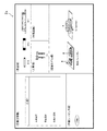
図1は、本発明の実施形態に係るロボット制御装置の構成図である。ロボット制御装置1は、1台又は複数台のロボット(例えば、産業用多関節ロボット)の動作を支援・管理する。ロボット制御装置1とロボットとは、ネットワークを介して通信することができる。図1では、1台のロボット制御装置1と3台のロボット30A,30B,30Cとが、ネットワークを介して通信可能に接続されている。なお、1台のロボット制御装置1に4台以上のロボット30が接続されていてもよい。また、1台のロボット制御装置1に1台のロボット30が接続された1つのロボットシステムが複数設けられていてもよい。   FIG. 1 is a configuration diagram of a robot control apparatus according to an embodiment of the present invention. The robot control device 1 supports and manages the operation of one or a plurality of robots (for example, an industrial articulated robot). The robot control device 1 and the robot can communicate via a network. In FIG. 1, one robot controller 1 and three robots 30A, 30B, and 30C are communicably connected via a network. Note that four or more robots 30 may be connected to one robot control device 1. A plurality of one robot system in which one robot 30 is connected to one robot control apparatus 1 may be provided.

本実施形態に係るロボット制御装置1は、ロボット30の導入前やロボット30の配置換えの前、すなわちロボット制御装置1とロボット30とがオフライン環境にある初期設定段階において、ロボット30の動作を制御するための動作制御プログラムを生成するものである。動作制御プログラムは、ロボット30が担う作業の内容を示す作業プログラムに、ロボット30の設置位置及び姿勢の情報を含む動作経路(動作パス)情報が関連付けられたものである。ロボット30は、動作制御プログラムに基づき所期の動作を実行する。ロボット制御装置1は、動作制御プログラムを生成するための機能として、ロボット30が担う作業に係る作業プログラムを生成するためのタスクプランニングを実行するタスクプランナとしての機能と、ロボット30の動作経路を生成するためのパスプランニングを実行するパスプランナとしての機能とを有している。   The robot control apparatus 1 according to the present embodiment controls the operation of the robot 30 before the introduction of the robot 30 or before the rearrangement of the robot 30, that is, at the initial setting stage where the robot control apparatus 1 and the robot 30 are in an offline environment. An operation control program for generating the program is generated. The motion control program is obtained by associating a motion program (motion path) information including information on the installation position and posture of the robot 30 with a work program indicating the content of work performed by the robot 30. The robot 30 executes a desired operation based on the operation control program. The robot control device 1 generates a function as a task planner for executing task planning for generating a work program related to work performed by the robot 30 and a movement path of the robot 30 as functions for generating an operation control program. And a function as a path planner for executing path planning for this purpose.

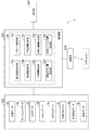
図1に示すように、ロボット制御装置1は、ハードディスクや半導体メモリなどの記憶部102と、CPUを中心に構成された制御部104と、ロボット30A,30B,30Cと通信するためのネットワークアダプタなどの通信部106と、タスクプランニング及びパスプランニングを実行する際に管理者に対して各種設定画面(操作画面)を表示する表示部107と、を有している。なお、タスクプランニング及びパスプランニングは、ロボット制御装置1にロボット30A,30B,30Cが接続される前の初期設定段階において実行されるものであるため、図1では便宜上、ロボット制御装置1に接続されるべきロボット30A,30B,30Cを、仮想的に示している。以下では、タスクプランニング及びパスプランニングそれぞれを実行するロボット制御装置1の構成について説明する。また以下では、主に、1台のロボット制御装置1と、これに接続されるべき1台のロボット30Aとを例に挙げる。   As shown in FIG. 1, the
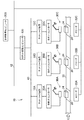
 robot control apparatus 1 includes a storage unit 102 such as a hard disk and a semiconductor memory, a control unit 104 mainly composed of a CPU, a network adapter for communicating with the robots 30A, 30B, and 30C. And a display unit 107 that displays various setting screens (operation screens) to the administrator when performing task planning and path planning. Note that task planning and path planning are executed at an initial setting stage before the robots 30A, 30B, and 30C are connected to the robot controller 1, and therefore, in FIG. The robots 30A, 30B, and 30C to be used are virtually shown. Below, the structure of the robot control apparatus 1 which performs each of task planning and path planning is demonstrated. In the following, one robot control device 1 and one robot 30A to be connected to the robot control device 1 will be mainly described as an example.

[タスクプランニング]
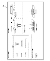
図2は、タスクプランニングを実行するための要素を含むロボット制御装置1の構成図である。同図に示すように、制御部104は、操作受付部11、作業取得部12、作業工程取得部13、部品情報取得部14、工具情報取得部15、パラメータ取得部16、ロボット情報取得部17、作業プログラム生成部18、及び表示制御部19を含んでいる。これらは、CPUを中心として構成された制御部104においてプログラムが実行されることにより実現される機能である。記憶部102には、記憶領域として、作業データ領域5a、テンプレートデータ領域5b、CADデータ領域5c、スキルデータ領域5d、ロボットデータ領域5e、作業プログラム領域5fが設けられている。
[Task planning]
FIG. 2 is a configuration diagram of the robot control apparatus 1 including elements for executing task planning. As shown in the figure, the control unit 104 includes an operation receiving unit 11, a work acquisition unit 12, a work process acquisition unit 13, a part information acquisition unit 14, a tool information acquisition unit 15, a parameter acquisition unit 16, and a robot information acquisition unit 17. , A work program generation unit 18 and a display control unit 19. These are functions realized by executing a program in the control unit 104 configured mainly with the CPU. The storage unit 102 is provided with a work data area 5a, a template data area 5b, a CAD data area 5c, a skill data area 5d, a robot data area 5e, and a work program area 5f as storage areas.

ロボット制御装置1の各要素の機能について説明する。   The function of each element of the robot control device 1 will be described.

表示制御部19は、管理者(オペレータ)の指示(操作)を受け付けるための各種設定画面を表示部107に表示させ、操作受付部11は、管理者の指示を受け付ける。管理者は、タスクプランニングの設定画面において、例えばロボット制御装置1に接続されたキーボードやマウス等の操作部(不図示)を使用して指示を行う。   The display control unit 19 displays various setting screens for accepting instructions (operations) from the administrator (operator) on the display unit 107, and the operation accepting unit 11 accepts instructions from the administrator. On the task planning setting screen, the administrator gives an instruction using an operation unit (not shown) such as a keyboard and a mouse connected to the robot control device 1, for example.

ロボット制御装置1は、管理者の指示内容に基づいて、ロボット30Aが担う作業の内容を示す作業プログラムを生成する。ここで、作業(ジョブ)は、複数の作業工程(サブジョブ)を含む。例えば、作業(ジョブ)としての「モータケーシング部品の組み付け」には、押し当て作業(工程1:サブジョブ1)、ピック作業(工程2:サブジョブ2)、及び挿入作業(工程3:サブジョブ3)の3つの作業工程(サブジョブ)が含まれる。ロボット30Aは、上記一連の作業工程を含む作業に対応する作業プログラムに基づき動作を行う。   The robot control device 1 generates a work program indicating the work content of the robot 30A based on the administrator's instruction content. Here, the work (job) includes a plurality of work processes (sub-jobs). For example, “assembly of motor casing parts” as work (job) includes pressing work (process 1: sub job 1), pick work (process 2: sub job 2), and insertion work (process 3: sub job 3). Three work processes (sub-jobs) are included. The robot 30A operates based on a work program corresponding to work including the above series of work steps.

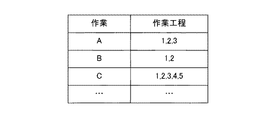
作業取得部12は、管理者が所望の作業を選択すると、その選択結果を取得する。選択対象の作業は作業データ領域5aに予め登録されており、管理者は、設定画面(設定画面0x)において複数の作業から、作業プログラムの作成をするべき作業を選択する。作業データ領域5aには、図3に示すように、例えば作業A、作業B、作業C等の作業名と、各作業に含まれる作業工程とが関連付けて記録された作業テーブルが記憶されている。例えば作業Aには、工程1(サブジョブ1)、工程2(サブジョブ2)、及び工程3(サブジョブ3)の3つの作業工程(サブジョブ)が関連付けられている。また作業取得部12は、管理者により選択された作業に関連付けられた作業工程の情報も取得する。   When the administrator selects a desired work, the work acquisition unit 12 acquires the selection result. The work to be selected is registered in advance in the work data area 5a, and the administrator selects a work for which a work program should be created from a plurality of work on the setting screen (setting screen 0x). As shown in FIG. 3, the work data area 5a stores a work table in which work names such as work A, work B, work C, and the like and work processes included in each work are recorded in association with each other. . For example, the operation A is associated with three operation steps (sub-jobs) of step 1 (sub-job 1), step 2 (sub-job 2), and step 3 (sub-job 3). The work acquisition unit 12 also acquires information on work processes associated with the work selected by the administrator.

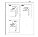
作業工程取得部13は、管理者が選択した作業に含まれる作業工程のうち管理者が設定画面(設定画面1x)において所望の作業工程を選択すると、その選択結果を取得するとともに、テンプレートデータ領域5bから、選択された作業工程に対応するサブジョブプログラム(工程作業プログラム)のテンプレートを取得する。テンプレートには、プログラムのスタイルや定型句などが保存されている。テンプレートデータ領域5bには、作業に含まれる作業工程に対応するサブジョブプログラムのテンプレートが記憶されている。作業工程が複数存在する場合は、作業工程毎にサブジョブプログラムのテンプレートが関連付けられている。例えば、図4に示すように、作業Aに対して、工程1(サブジョブ1)、工程2(サブジョブ2)、及び工程3(サブジョブ3)の3つの作業工程(サブジョブ)のプログラムのテンプレートが記憶されている。   When the administrator selects a desired work process on the setting screen (setting screen 1x) among the work processes included in the work selected by the administrator, the work process acquiring unit 13 acquires the selection result and the template data area. From 5b, a template of a sub job program (process work program) corresponding to the selected work process is acquired. Templates store program styles and boilerplate. The template data area 5b stores a template for a sub job program corresponding to a work process included in the work. When there are a plurality of work processes, a sub-job program template is associated with each work process. For example, as shown in FIG. 4, a template of a program for three work processes (sub job) of process 1 (sub job 1), process 2 (sub job 2), and process 3 (sub job 3) is stored for work A. Has been.

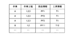
部品情報取得部14は、管理者が選択した作業に対応する部品(作業対象物)の情報や、管理者が設定画面(設定画面2x)において選択した部品の情報を、CADデータ領域5cから取得する。CADデータ領域5cには、図5に示すように、作業、作業工程、及び部品情報が関連付けて記録されたCADデータテーブルが記憶されている。部品情報には、部品名、部品の識別情報(部品ID)、部品の3次元モデルデータが含まれる。また部品情報取得部14は、管理者が設定画面(設定画面2x)において選択した作業台の情報を、CADデータ領域5cから取得する。各部品情報には、座標系(部品座標系)が関連付けられ、作業台の情報には、座標系(作業座標系)が関連付けられている。   The component information acquisition unit 14 acquires from the CAD data area 5c information on the component (work object) corresponding to the operation selected by the administrator and information on the component selected on the setting screen (setting screen 2x) by the administrator. To do. The CAD data area 5c stores a CAD data table in which work, work process, and part information are recorded in association with each other, as shown in FIG. The component information includes a component name, component identification information (component ID), and three-dimensional model data of the component. Further, the component information acquisition unit 14 acquires information on the work table selected by the administrator on the setting screen (setting screen 2x) from the CAD data area 5c. A coordinate system (component coordinate system) is associated with each component information, and a coordinate system (work coordinate system) is associated with work table information.

工具情報取得部15は、管理者が選択した作業に対応する工具の情報や、管理者が設定画面(設定画面2x)において選択した工具の情報を、CADデータ領域5cから取得する。CADデータ領域5cのCADデータテーブルにはさらに、図5に示すように、工具情報が関連付けて記録されている。工具情報には、工具名、工具の識別情報(工具ID)、工具の3次元モデルデータが含まれる。また、各工具情報には、座標系(工具座標系)が関連付けられている。   The tool information acquisition unit 15 acquires information on the tool corresponding to the work selected by the administrator and information on the tool selected on the setting screen (setting screen 2x) from the CAD data area 5c. Further, tool information is recorded in association with the CAD data table in the CAD data area 5c as shown in FIG. The tool information includes a tool name, tool identification information (tool ID), and tool three-dimensional model data. Each tool information is associated with a coordinate system (tool coordinate system).

パラメータ取得部16は、管理者が設定画面(設定画面3x)において設定した作業パラメータ(作業条件)を取得する。また、パラメータ取得部16は、スキルデータ領域5dを参照して、管理者が設定した作業パラメータが、作業工程に適切な値(予め設定された規定パラメータ(閾値))を満たすか否かを判定する。すなわち、パラメータ取得部16は判定部としての機能も有する。スキルデータ領域5dには、図6に示すように、作業、作業工程、及び規定パラメータが関連付けて記録された作業パラメータテーブルが記憶されている。作業パラメータは、例えば部品間の距離、位置、押し当て力、把持力などである。   The parameter acquisition unit 16 acquires work parameters (work conditions) set by the administrator on the setting screen (setting screen 3x). Further, the parameter acquisition unit 16 refers to the skill data area 5d and determines whether or not the work parameter set by the administrator satisfies a value appropriate for the work process (a preset parameter (threshold) set in advance). To do. That is, the parameter acquisition unit 16 also has a function as a determination unit. In the skill data area 5d, as shown in FIG. 6, a work parameter table in which work, work process, and specified parameters are recorded in association with each other is stored. The work parameter is, for example, a distance between parts, a position, a pressing force, a gripping force, or the like.

ロボット情報取得部17は、管理者が設定画面(設定画面4x)において選択したロボットの情報を、ロボットデータ領域5eから取得する。ロボットデータ領域5eには、図7に示すように、作業及びロボット情報が関連付けて記録されたロボット情報テーブルが記憶されている。ロボット情報には、ロボット名、ロボットの識別情報(ロボットID)、ロボットの外形状を示す3次元モデルデータが含まれる。また各ロボット情報には、座標系(ロボット座標系)が関連付けられている。   The robot information acquisition unit 17 acquires information about the robot selected by the administrator on the setting screen (setting screen 4x) from the robot data area 5e. The robot data area 5e stores a robot information table in which work and robot information are recorded in association with each other as shown in FIG. The robot information includes robot name, robot identification information (robot ID), and three-dimensional model data indicating the outer shape of the robot. Each robot information is associated with a coordinate system (robot coordinate system).

作業プログラム生成部18は、作業工程取得部13により取得されたサブジョブプログラムのテンプレートに、部品情報取得部14により取得された部品情報、工具情報取得部15により取得された工具情報、パラメータ取得部16により取得された作業パラメータ、及び、ロボット情報取得部17により取得されたロボット情報を組み込み、サブジョブプログラムを生成する。また、作業プログラム生成部18は、生成したサブジョブプログラムに基づき、作業に対応する作業プログラムを生成する。作業プログラム生成部18は、生成した作業プログラムをサブジョブプログラムに関連付けて作業プログラム領域5fに記憶する。   The work program generation unit 18 adds the component information acquired by the component information acquisition unit 14, the tool information acquired by the tool information acquisition unit 15, and the parameter acquisition unit 16 to the sub job program template acquired by the work process acquisition unit 13. The work parameters acquired by the above and the robot information acquired by the robot information acquisition unit 17 are incorporated to generate a sub job program. Further, the work program generation unit 18 generates a work program corresponding to the work based on the generated sub job program. The work program generation unit 18 stores the generated work program in the work program area 5f in association with the sub job program.

また、ロボット制御装置1では、表示制御部19が、上記各要素の処理に応じた設定画面(上記設定画面0x〜4xを含む)を表示部107に表示させる。各設定画面の具体例は後述する。タスクプランニングにおける設定画面には、例えば図8に示すように、部品欄、工具欄、半製品欄、環境モデル欄、作業工程欄、作業シーケンス欄が含まれる。   Further, in the robot control apparatus 1, the display control unit 19 causes the display unit 107 to display setting screens (including the setting screens 0x to 4x) according to the processing of each element. Specific examples of each setting screen will be described later. For example, as shown in FIG. 8, the setting screen in task planning includes a parts column, a tool column, a semi-finished product column, an environmental model column, a work process column, and a work sequence column.

表示制御部19は、各設定画面を表示させるための要素として、図9に示すように、設定画面表示部19a、部品欄設定部19b、工具欄設定部19c、環境モデル欄設定部19d、パラメータ設定部19e、半製品欄設定部19f、作業工程欄設定部19g、作業シーケンス欄設定部19hを含んでいる。また、記憶部102には、記憶領域としてさらに、設定画面データ領域5g、部品データ領域5hが設けられている。なお、図9では、図2に示した制御部104に設けられる各要素は省略している。   As shown in FIG. 9, the display control unit 19 includes a setting screen display unit 19a, a part field setting unit 19b, a tool field setting unit 19c, an environment model field setting unit 19d, and parameters as elements for displaying each setting screen. It includes a setting unit 19e, a semi-finished product column setting unit 19f, a work process column setting unit 19g, and a work sequence column setting unit 19h. The storage unit 102 is further provided with a setting screen data area 5g and a component data area 5h as storage areas. In FIG. 9, each element provided in the control unit 104 shown in FIG. 2 is omitted.

管理者が選択した作業が作業取得部12により取得されると、設定画面表示部19aは、設定画面データ領域5gから、管理者が選択した作業に対応する設定画面を取得し、部品欄設定部19bは、部品情報取得部14により取得された部品の3次元モデルデータをCADデータ領域5c(図5参照)から取得して設定画面の部品欄に設定(登録)し、工具欄設定部19cは、工具情報取得部15により取得された工具の3次元モデルデータをCADデータ領域5cから取得して設定画面の工具欄に設定(登録)し、環境モデル欄設定部19dは、部品情報取得部14により取得された部品及び作業取得部12により取得された作業により製造される製品の3次元モデルデータをCADデータ領域5cから取得して設定画面の環境モデル欄に設定(登録)する。各欄に設定された3次元モデルデータは設定画面に画像として表示される。また部品欄設定部19bは、部品欄に設定した各部品の3次元モデルデータを部品データ領域5hに記憶する。   When the operation selected by the administrator is acquired by the operation acquisition unit 12, the setting screen display unit 19a acquires a setting screen corresponding to the operation selected by the administrator from the setting screen data area 5g, and the part field setting unit 19b acquires the three-dimensional model data of the part acquired by the part information acquisition unit 14 from the CAD data area 5c (see FIG. 5) and sets (registers) it in the part column of the setting screen. The tool column setting unit 19c The three-dimensional model data of the tool acquired by the tool information acquisition unit 15 is acquired from the CAD data area 5c and set (registered) in the tool column of the setting screen. The environment model column setting unit 19d is a component information acquisition unit 14 The three-dimensional model data of the parts acquired by the above and the product manufactured by the work acquired by the work acquisition unit 12 are acquired from the CAD data area 5c and are displayed in the environment model column of the setting screen. A constant (registered). The 3D model data set in each field is displayed as an image on the setting screen. The part column setting unit 19b stores the three-dimensional model data of each part set in the part column in the part data area 5h.

半製品欄設定部19fは、部品データ領域5hを参照して、各作業工程が実行された段階(途中の製造状態(半製品))の3次元モデルデータを取得し、設定画面の半製品欄に設定(登録)する。設定画面の半製品欄には、半製品の画像が表示される。   The semi-finished product column setting unit 19f refers to the part data area 5h, acquires the three-dimensional model data at the stage where each work process is executed (intermediate manufacturing state (semi-finished product)), and the semi-finished product column on the setting screen. Set (register). An image of the semi-finished product is displayed in the semi-finished product column of the setting screen.

作業工程欄設定部19gは、設定画面上で管理者により選択された選択対象物(部品、工具等の3次元モデルデータ)を、設定画面の作業工程欄に設定(登録)する。作業工程欄に設定する方法は、例えば部品欄に設定(表示)された部品画像を管理者がマウスポインタでドラッグし、作業工程欄にドロップする方法であってもよいし、作業工程欄に複数の部品名を一覧表示させて、管理者がマウスポインタで所望の部品名をクリックする方法であってもよい。設定画面の作業工程欄には、設定された部品、工具等の画像が表示される。   The work process column setting unit 19g sets (registers) the selection target (three-dimensional model data such as parts and tools) selected by the administrator on the setting screen in the work process column of the setting screen. The method of setting in the work process column may be, for example, a method in which the administrator drags a part image set (displayed) in the component field with the mouse pointer and drops it in the work process column. The part names may be displayed as a list, and the administrator may click the desired part name with the mouse pointer. Images of set parts, tools, and the like are displayed in the work process column of the setting screen.

作業シーケンス欄設定部19hは、各作業工程に対応する工程名を作業シーケンス欄に設定(登録)する。各工程名には、サブジョブプログラムが関連付けられており、工程名を選択(クリック)すると、対応するサブジョブプログラムの内容が設定画面に表示される。   The work sequence field setting unit 19h sets (registers) a process name corresponding to each work process in the work sequence field. Each process name is associated with a sub job program. When a process name is selected (clicked), the contents of the corresponding sub job program are displayed on the setting screen.

ここで、ロボット制御装置1における作業プログラムの生成方法(タスクプランニング)について、具体例を挙げて説明する。ここでは、「モータケーシング部品の組み付け」の作業(以下、作業Aと称す。)に対応する作業プログラムの生成方法を例に挙げる。また、作業Aには、押し当て作業(工程1)、ピック作業(工程2)、及び挿入作業(工程3)の3つの作業工程が含まれるものとする。   Here, a method for generating a work program (task planning) in the robot control apparatus 1 will be described with a specific example. Here, a method for generating a work program corresponding to the work of “assembly of motor casing parts” (hereinafter referred to as work A) will be described as an example. In addition, the operation A includes three operation processes, that is, a pressing operation (process 1), a picking operation (process 2), and an insertion operation (process 3).

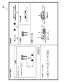
図10及び図11は、ロボット制御装置1の動作を示す図である。同図では、管理者の操作フローと、管理者の操作に基づくロボット制御装置1の動作フローと、表示部107の表示フローとを並行して示している。なお、表示部107の表示処理は、ロボット制御装置1における表示制御部19の表示命令に従って行われる。   10 and 11 are diagrams illustrating the operation of the robot control apparatus 1. In the figure, the operation flow of the administrator, the operation flow of the robot control apparatus 1 based on the operation of the administrator, and the display flow of the display unit 107 are shown in parallel. Note that the display processing of the display unit 107 is performed in accordance with a display command of the display control unit 19 in the robot control apparatus 1.

まず、タスクプランニングの処理が開始されると、表示部107に初期設定画面が表示される(S101)。初期設定画面には、例えば図12に示すように、管理者に作業を選択させるための画面(設定画面0x)が表示される。管理者は、図12の初期設定画面において、作業として「作業A」を選択して決定ボタンを押下する(S102)。作業取得部12が管理者による選択結果(作業A)を取得すると、部品情報取得部14は、CADデータ領域5c(図5参照)から作業Aに対応する部品PF1,PF2,PF3の3次元モデルデータを取得し、工具情報取得部15は、CADデータ領域5cから作業Aに対応する工具T1の3次元モデルデータを取得する(S103)。   First, when the task planning process is started, an initial setting screen is displayed on the display unit 107 (S101). On the initial setting screen, for example, as shown in FIG. 12, a screen (setting screen 0x) for allowing the administrator to select a work is displayed. The administrator selects “Work A” as the work on the initial setting screen of FIG. 12 and presses the enter button (S102). When the work obtaining unit 12 obtains the selection result (work A) by the administrator, the part information obtaining unit 14 obtains a three-dimensional model of the parts PF1, PF2, and PF3 corresponding to the work A from the CAD data area 5c (see FIG. 5). Data is acquired, and the tool information acquisition unit 15 acquires the three-dimensional model data of the tool T1 corresponding to the work A from the CAD data area 5c (S103).

次に、設定画面表示部19aは、設定画面データ領域5gから作業Aに対応する設定画面(図8参照)を取得し、部品欄設定部19bは、上記取得された部品PF1,PF2,PF3の3次元モデルデータを設定画面の部品欄に設定し、工具欄設定部19cは、上記取得された工具T1の3次元モデルデータを設定画面の工具欄に設定し、環境モデル欄設定部19dは、部品PF1,PF2,PF3、作業台WS1、及び完成品の3次元モデルデータを設定画面の環境モデル欄に設定する。また、作業工程欄設定部19gは、作業Aに含まれる工程1〜工程3の情報を設定画面の作業工程欄に設定し、作業シーケンス欄設定部19hは、設定画面の作業シーケンス欄に工程0を設定する。これにより表示部107には、各設定部により各表示欄が設定された設定画面1xが表示される(S104)。図13には、設定画面1xの一例を示している。   Next, the setting screen display unit 19a acquires a setting screen (see FIG. 8) corresponding to the work A from the setting screen data area 5g, and the part column setting unit 19b acquires the parts PF1, PF2, and PF3 that have been acquired. The 3D model data is set in the parts field of the setting screen, the tool field setting unit 19c sets the acquired 3D model data of the tool T1 in the tool field of the setting screen, and the environment model field setting unit 19d The three-dimensional model data of the parts PF1, PF2, PF3, the work bench WS1, and the finished product are set in the environment model column of the setting screen. Further, the work process column setting unit 19g sets the information of the processes 1 to 3 included in the work A in the work process column of the setting screen, and the work sequence column setting unit 19h includes the process 0 in the work sequence column of the setting screen. Set. As a result, the setting screen 1x in which each display field is set by each setting unit is displayed on the display unit 107 (S104). FIG. 13 shows an example of the setting screen 1x.

次に、設定画面1xにおいて、管理者が作業Aに含まれる「工程1」を選択する(S105)。例えば、管理者はマウスを使用して設定画面上の「工程1」をクリックする。管理者により「工程1」が選択されると、作業工程取得部13は、テンプレートデータ領域5b(図4参照)から、「工程1」に対応するサブジョブ1プログラムのテンプレートを取得し(S106)、作業工程欄設定部19gは、部品、工具及び作業台を設定するための設定欄を作業工程欄に表示させる(S107)。図14には、上記設定欄を含む設定画面2xの一例を示している。   Next, on the setting screen 1x, the administrator selects “Step 1” included in the operation A (S105). For example, the administrator uses the mouse to click “Step 1” on the setting screen. When the “process 1” is selected by the administrator, the work process acquiring unit 13 acquires the template of the sub job 1 program corresponding to “process 1” from the template data area 5b (see FIG. 4) (S106). The work process column setting unit 19g displays a setting column for setting parts, tools, and work tables in the work process column (S107). FIG. 14 shows an example of the setting screen 2x including the setting field.

次に、設定画面2xにおいて、管理者が部品PF1、工具T1及び作業台WS1を選択する(S108)。例えば、管理者は、マウスを使用して設定画面2xの部品欄に設定されている部品PF1をドラッグして作業工程欄にドロップし、工具欄に設定されている工具T1をドラッグして作業工程欄にドロップし、環境モデル欄に設定されている作業台WS1をドラッグして作業工程欄にドロップする。これにより、作業工程欄設定部19gは、部品PF1、作業台WS1及び工具T1を作業工程欄に設定し、設定画面2xが図15に示すように更新される(S109)。また部品情報取得部14は、管理者により選択された部品PF1及び作業台WS1の情報をCADデータ領域5cから取得し、工具情報取得部15は、管理者により選択された工具T1の情報をCADデータ領域5cから取得する(S110)。なお、部品PF1、作業台WS1及び工具T1の情報には、各座標系が関連付けられている。   Next, on the setting screen 2x, the administrator selects the part PF1, the tool T1, and the workbench WS1 (S108). For example, the administrator uses the mouse to drag the part PF1 set in the part field of the setting screen 2x and drop it on the work process field, and drag the tool T1 set in the tool field to perform the work process. Drop it in the field and drag the work bench WS1 set in the environmental model field and drop it in the work process field. Thereby, the work process column setting unit 19g sets the part PF1, the work bench WS1, and the tool T1 in the work process column, and the setting screen 2x is updated as shown in FIG. 15 (S109). Further, the component information acquisition unit 14 acquires information on the component PF1 and work bench WS1 selected by the administrator from the CAD data area 5c, and the tool information acquisition unit 15 acquires information on the tool T1 selected by the administrator in CAD. Obtained from the data area 5c (S110). Each coordinate system is associated with information on the component PF1, the work bench WS1, and the tool T1.

次に、作業工程欄設定部19gは、作業パラメータを設定するための設定欄を作業工程欄に表示させる(S111)。図16には、上記設定欄を含む設定画面3xの一例を示している。   Next, the work process field setting unit 19g displays a setting field for setting work parameters in the work process field (S111). FIG. 16 shows an example of the setting screen 3x including the setting field.

次に、設定画面3xにおいて、管理者が作業パラメータを設定(入力)する(S112)。例えば、管理者は、作業台WS1と部品PF1との距離(接近高さ)D(mm)=30と、押し当て反力F(N)=5を設定する。これにより設定画面3xは、図17に示すように更新される(S113)。   Next, the administrator sets (inputs) work parameters on the setting screen 3x (S112). For example, the administrator sets the distance (approach height) D (mm) = 30 and the pressing reaction force F (N) = 5 between the work bench WS1 and the component PF1. As a result, the setting screen 3x is updated as shown in FIG. 17 (S113).

管理者により作業パラメータが設定されると、パラメータ取得部16は、作業パラメータが予め設定された規定パラメータ(閾値)を満たすか否かを判定する(S114)。作業パラメータが閾値を満たさない場合、表示制御部19は、作業パラメータの再入力を促すメッセージを表示部107に表示させる(S115)。   When the work parameter is set by the administrator, the parameter acquisition unit 16 determines whether or not the work parameter satisfies a preset parameter (threshold value) set in advance (S114). When the work parameter does not satisfy the threshold value, the display control unit 19 causes the display unit 107 to display a message for prompting re-input of the work parameter (S115).

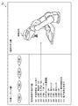
作業パラメータが閾値を満たす場合、作業工程欄設定部19gは、ロボットを選択するための設定欄を作業工程欄に表示させる(S116)。図18には、上記設定欄を含む設定画面4xの一例を示している。   When the work parameter satisfies the threshold, the work process field setting unit 19g displays a setting field for selecting a robot in the work process field (S116). FIG. 18 shows an example of the setting screen 4x including the setting field.

次に、設定画面4xにおいて、管理者がロボット30Aを選択する(S117)。ロボット情報取得部17は、管理者により選択されたロボット30Aの情報を、ロボットデータ領域5e(図7参照)から取得する(S118)。ロボット30Aの情報には、ロボット座標系が関連付けられている。   Next, on the setting screen 4x, the administrator selects the robot 30A (S117). The robot information acquisition unit 17 acquires information on the robot 30A selected by the administrator from the robot data area 5e (see FIG. 7) (S118). A robot coordinate system is associated with the information of the robot 30A.

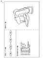
次に、管理者が、設定画面4xに含まれる設定完了ボタンを押下すると(S119)、作業プログラム生成部18は、サブジョブ1プログラムのテンプレートに、部品PF1、工具T1、作業台WS1、作業パラメータ(D=30、F=5)、ロボット30Aの各情報を組み込み、サブジョブ1プログラム(図22参照)を生成する(S120)。また、半製品欄設定部19fは、作業台WS1に部品PF1を押し当てた状態(半製品:工程1の完成品)を設定画面の半製品欄に設定し、作業シーケンス欄設定部19hは、サブジョブ1プログラムが関連付けられた「工程1」を作業シーケンス欄に設定する(S121)。図19には、上記設定された設定画面5xの一例を示している。作業シーケンス欄の「工程1」をクリックすると、サブジョブ1プログラム(図22参照)の内容が表示される。   Next, when the administrator depresses a setting completion button included in the setting screen 4x (S119), the work program generation unit 18 adds the component PF1, tool T1, work bench WS1, work parameters ( D = 30, F = 5), each information of the robot 30A is incorporated, and a sub job 1 program (see FIG. 22) is generated (S120). Further, the semi-finished product column setting unit 19f sets a state (semi-finished product: completed product of process 1) pressed against the work bench WS1 in the semi-finished product column of the setting screen, and the work sequence column setting unit 19h “Process 1” associated with the sub job 1 program is set in the work sequence column (S121). FIG. 19 shows an example of the setting screen 5x set as described above. When “Step 1” is clicked in the work sequence column, the contents of the sub job 1 program (see FIG. 22) are displayed.

次に、管理者がタスクプランニングの続行指示を行う(例えば設定画面5xの「次工程へ」をクリックする)と(S122)、表示部107には、再び、各設定部により各欄が設定された設定画面1xが表示される(S123)。管理者は、設定画面1x(図13参照)において作業Aに含まれる「工程2」を選択する(S123)。以降、上述したS106〜S120と同様の処理が行われ、「工程2」に対応するサブジョブ2プログラム(図22参照)が生成される。図20には、工程2における設定画面5xの一例を示している。さらに、作業Aに含まれる「工程3」に対しても同様の処理が行われ、これにより「工程3」に対応するサブジョブ3プログラム(図22参照)が生成される。図21には、工程3における設定画面5xの一例を示している。   Next, when the administrator gives an instruction to continue the task planning (for example, clicks “go to next process” on the setting screen 5x) (S122), each column is set again by each setting unit on the display unit 107. The setting screen 1x is displayed (S123). The administrator selects “Step 2” included in the operation A on the setting screen 1x (see FIG. 13) (S123). Thereafter, the same processing as S106 to S120 described above is performed, and a sub job 2 program (see FIG. 22) corresponding to “Step 2” is generated. FIG. 20 shows an example of the setting screen 5x in step 2. Further, the same processing is performed for “step 3” included in the operation A, thereby generating a sub job 3 program (see FIG. 22) corresponding to “step 3”. FIG. 21 shows an example of the setting screen 5x in step 3.

最後に、管理者がタスクプランニングの完了指示を行う(例えば設定画面5xの「完了」をクリックする)と(S125)、作業プログラム生成部18は、作業Aに含まれる工程1〜3に対応するサブジョブ1プログラム、サブジョブ2プログラム及びサブジョブ3プログラムに基づき、作業Aに対応する作業プログラムを生成する(S126)。図22には、サブジョブ1プログラム、サブジョブ2プログラム及びサブジョブ3プログラムと、これらサブジョブプログラムにより生成される、作業Aに対応する作業プログラムの例を示している。作業プログラム生成部18は、作業Aに対応する作業プログラムを、サブジョブ1プログラム、サブジョブ2プログラム及びサブジョブ3プログラムに関連付けて、作業プログラム領域5fに記憶する。   Finally, when the administrator gives an instruction to complete task planning (for example, clicks “Done” on the setting screen 5x) (S125), the work program generation unit 18 corresponds to steps 1 to 3 included in the work A. Based on the sub job 1 program, the sub job 2 program, and the sub job 3 program, a work program corresponding to the work A is generated (S126). FIG. 22 shows an example of a sub job 1 program, a sub job 2 program, a sub job 3 program, and a work program corresponding to work A generated by these sub job programs. The work program generation unit 18 stores the work program corresponding to the work A in the work program area 5f in association with the sub job 1 program, the sub job 2 program, and the sub job 3 program.

本実施形態に係るロボット制御装置1のタスクプランニングによれば、ロボットが担う作業の内容を示す作業プログラムを容易に作成することができるとともに、管理者は作業プログラムの生成過程(状況)を把握(視認)することができる。また、上記タスクプランニングにより生成された作業プログラムは、作業内容を記述したものでありロボット及び作業台の位置情報を含まないため、例えばロボットの種類や位置が変更された場合にも利用することができる。   According to the task planning of the robot control apparatus 1 according to the present embodiment, it is possible to easily create a work program indicating the content of work performed by the robot, and the administrator grasps the generation process (situation) of the work program ( Visual recognition). In addition, the work program generated by the task planning described the work contents and does not include the position information of the robot and the workbench, so it can be used even when the type or position of the robot is changed, for example. it can.

[パスプランニング]
上記のタスクプランニングの処理が終了すると、続いて、管理者は、ロボット制御装置1に、ロボット30Aの設置位置及び姿勢の情報を含む軌道(動作経路)を生成するためのパスプランニングの処理を実行させる。以下、パスプランニングの処理について説明する。なお、説明の便宜上、上記タスクプランニングを実行するための要素と同一の機能を有する要素には同一の符号を付し、その説明を省略する。
[Path planning]
When the above task planning process is completed, the administrator subsequently executes a path planning process for generating a trajectory (motion path) including information on the installation position and orientation of the robot 30A in the robot control device 1. Let The path planning process will be described below. For convenience of explanation, elements having the same functions as the elements for executing the task planning are denoted by the same reference numerals and description thereof is omitted.

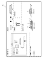
制御部104は、パスプランニングを実行するための要素として、図23に示すように、プログラム取得部21、位置取得部22、動作判定部23、経路生成部24、位置調整部25、動作制御プログラム生成部26、尤度算出部27を含んでいる。これらは、CPUを中心として構成された制御部104においてプログラムが実行されることにより実現される機能である。また記憶部102には、記憶領域として、位置データ領域5i、動作制御プログラム領域5jが設けられている。   As shown in FIG. 23, the control unit 104 includes a program acquisition unit 21, a position acquisition unit 22, an operation determination unit 23, a path generation unit 24, a position adjustment unit 25, and an operation control program as elements for executing path planning. A generation unit 26 and a likelihood calculation unit 27 are included. These are functions realized by executing a program in the control unit 104 configured mainly with the CPU. The storage unit 102 is provided with a position data area 5i and an operation control program area 5j as storage areas.

また表示制御部19は、上記タスクプランニングと同様、管理者の指示を受け付けるための各種設定画面を表示部107に表示させ、操作受付部11は、管理者の指示を受け付ける。管理者は、パスプランニングの設定画面において、例えばロボット制御装置1に接続されたキーボードやマウス等の操作部を使用して指示を行う。   Similarly to the task planning, the display control unit 19 displays various setting screens for accepting instructions from the administrator on the display unit 107, and the operation accepting unit 11 accepts instructions from the administrator. On the setting screen for path planning, the administrator gives an instruction using an operation unit such as a keyboard or a mouse connected to the robot control device 1.

ロボット制御装置1は、管理者の指示内容に基づいて、ロボット30が作業プログラムに係る作業を実行するためのロボット30の動作経路を生成する。ここでは、ロボット30Aに関する、上記作業A、作業Aに含まれる工程1、工程2、工程3を例に挙げる。   The robot control device 1 generates an operation path of the robot 30 for the robot 30 to perform the work related to the work program based on the content of the instruction from the administrator. Here, the process A, the process 1, the process 2 and the process 3 included in the work A related to the robot 30A will be described as an example.

ロボット制御装置1の各要素の機能について説明する。   The function of each element of the robot control device 1 will be described.

作業プログラム領域5fには、作業Aに対応する作業プログラムが、サブジョブ1プログラム、サブジョブ2サブプログラム及びサブジョブ3プログラムに関連付けて記憶されている。上記タスクプランニングで生成された作業プログラムに係る各サブジョブプログラム(図22参照)の位置・座標情報を表す記述(例えば、Coord、P1、P2)は不定であり、パスプランニングの処理により決定される。なお、「Coord」は、例えば(x、y、z)の座標情報を表し、Coord1の座標系ファイル1がサブジョブ1プログラムに関連付けられ、Coord2の座標系ファイル2がサブジョブ2プログラムに関連付けられ、Coord3の座標系ファイル3がサブジョブ3プログラムに関連付けられて作業プログラム領域5fに記憶されている。   In the work program area 5f, a work program corresponding to the work A is stored in association with the sub job 1 program, the sub job 2 sub program, and the sub job 3 program. The description (for example, Coord, P1, P2) representing the position / coordinate information of each sub job program (see FIG. 22) related to the work program generated by the task planning is indefinite and is determined by the path planning process. Note that “Coord” represents coordinate information of (x, y, z), for example, Coord1 coordinate system file 1 is associated with the sub job 1 program, Coord2 coordinate system file 2 is associated with the sub job 2 program, and Coord3 Is stored in the work program area 5f in association with the sub job 3 program.

位置データ領域5iには、部品、工具、作業台、ロボットの各座標系が記憶される。例えば、部品PF1,PF2,PF3、工具T1、作業台WS1、ロボット30Aの各座標系が記憶されている。また、位置データ領域5iには、ロボットの設置位置に対する、部品、工具、及び作業台の設計上の相対位置(位置測定データ)が記憶される。これにより、例えば部品PF1,PF2,PF3、工具T1、作業台WS1、ロボット30Aの位置関係(座標位置)が特定される。なお、ロボット30A,30B,30Cは人手で任意にロボット設置位置に配置されるので、それらロボット30A,30B,30Cに対する各作業台の実際の相対位置は、設計上のそれとは異なり得る。部品、工具、及び作業台38の設計上の相対位置は、各ロボット設置位置に関連づけて記憶されている。このように、位置データ領域5iには、各ロボットの座標位置が、各ロボット識別情報に関連付けて記憶されている。   In the position data area 5i, coordinate systems of parts, tools, work tables, and robots are stored. For example, the coordinate systems of the parts PF1, PF2, PF3, tool T1, workbench WS1, and robot 30A are stored. The position data area 5i stores relative positions (position measurement data) in designing the parts, tools, and work table with respect to the installation position of the robot. Thereby, for example, the positional relationship (coordinate position) of the parts PF1, PF2, PF3, the tool T1, the workbench WS1, and the robot 30A is specified. Since the robots 30A, 30B, and 30C are arbitrarily arranged at the robot installation positions manually, the actual relative positions of the respective work tables with respect to the robots 30A, 30B, and 30C may be different from those in the design. Relative design positions of the parts, tools, and work table 38 are stored in association with each robot installation position. Thus, the coordinate position of each robot is stored in the position data area 5i in association with each robot identification information.

動作制御プログラム領域5jには、上記タスクプランニングより生成された作業プログラムに、パスプランニングにより生成された動作経路が関連付けられた動作制御プログラムが記憶される。   The operation control program area 5j stores an operation control program in which an operation path generated by path planning is associated with a work program generated by the task planning.

プログラム取得部21は、作業プログラム領域5fから、パスプランニングの処理対象となる作業プログラムを取得する。ここでは、作業Aに対応する作業プログラムを取得する。この作業プログラムには、サブジョブ1プログラム、サブジョブ2プログラム及びサブジョブ3プログラムと、座標系ファイル1,2,3とがそれぞれ関連付けられている。プログラム取得部21は、例えば、管理者がパスプランニングを開始する指示を行ったときに、上記作業プログラムを取得する。   The program acquisition unit 21 acquires a work program to be processed for path planning from the work program area 5f. Here, a work program corresponding to work A is acquired. This work program is associated with sub job 1 program, sub job 2 program, sub job 3 program, and coordinate system files 1, 2, and 3, respectively. The program acquisition unit 21 acquires the work program, for example, when the administrator gives an instruction to start path planning.

位置取得部22は、位置データ領域5iから、部品、工具、作業台、ロボットの位置(座標系)を取得する。ここでは、部品PF1,PF2,PF3、工具T1、作業台WS1、ロボット30Aの位置(座標系)を取得する。   The position acquisition unit 22 acquires the positions (coordinate systems) of parts, tools, work tables, and robots from the position data area 5i. Here, the positions (coordinate systems) of the parts PF1, PF2, PF3, tool T1, workbench WS1, and robot 30A are acquired.

動作判定部23は、位置取得部22により取得された位置情報に基づいて、各工程における動作において、動作の開始点及び到達点が可動範囲内(所定範囲内)にあるか否かを判定する。なお可動範囲は、位置取得部22により取得された位置情報に基づいて算出される。また、動作判定部23は、位置取得部22により取得された位置情報に基づいて、各工程における動作において、ロボット30Aが他のロボット30B,30Cや周辺の物体等の被干渉物に干渉するか否かを判定する。すなわち、動作判定部23は、動作範囲チェック及び干渉チェックを行う。動作判定部23は、動作範囲チェックにおいて動作の開始点及び到達点が可動範囲内にある場合は正常と判定し、干渉チェックにおいてロボットが被干渉物に干渉しない場合は正常と判定し、これら以外は異常と判定する。動作範囲チェック及び干渉チェックは、CADデータ領域5cに記憶される3次元モデルデータを用いて、ロボット30の作業空間における動きを仮想空間内でシミュレーションして行うことができる。   Based on the position information acquired by the position acquisition unit 22, the operation determination unit 23 determines whether the start point and the arrival point of the operation are within a movable range (within a predetermined range) in the operation in each process. . The movable range is calculated based on the position information acquired by the position acquisition unit 22. Further, based on the position information acquired by the position acquisition unit 22, the operation determination unit 23 determines whether the robot 30A interferes with an interfered object such as another robot 30B, 30C or a surrounding object in the operation in each process. Determine whether or not. That is, the motion determination unit 23 performs a motion range check and an interference check. The movement determination unit 23 determines that the movement start point and the arrival point are within the movable range in the movement range check, and determines that the robot is normal when the robot does not interfere with the interfered object in the interference check. Is determined to be abnormal. The motion range check and the interference check can be performed by simulating the movement of the robot 30 in the work space using the three-dimensional model data stored in the CAD data area 5c.

経路生成部24は、動作判定部23による判定結果に基づいて、製造工程順における前後の工程間のロボットの動作経路を生成する。例えば、経路生成部24は、工程0と工程1の間のロボット30Aの動作経路0−1を生成し、工程1と工程2の間のロボット30Aの動作経路1−2を生成し、工程2と工程3の間のロボット30Aの動作経路2−3を生成する。また経路生成部24は、生成した各動作経路情報を作業プログラム領域5fに記憶する。   The path generation unit 24 generates an operation path of the robot between the previous and subsequent processes in the order of the manufacturing process based on the determination result by the operation determination unit 23. For example, the path generation unit 24 generates the operation path 0-1 of the robot 30A between the process 0 and the process 1, generates the operation path 1-2 of the robot 30A between the process 1 and the process 2, and the process 2 And an operation path 2-3 of the robot 30A between Step 3 and Step 3 is generated. The path generation unit 24 stores the generated operation path information in the work program area 5f.

位置調整部25は、動作判定部23による判定結果が異常の場合に、作業台とロボットとの位置関係を仮想空間内で調整する。   The position adjustment unit 25 adjusts the positional relationship between the work table and the robot in the virtual space when the determination result by the operation determination unit 23 is abnormal.

動作制御プログラム生成部26は、経路生成部24により生成された動作経路を、上記タスクプランニングより生成された作業プログラムに関連付けて動作制御プログラムを生成する。動作制御プログラム生成部26は、生成した動作制御プログラムを動作制御プログラム領域5jに記憶する。   The operation control program generation unit 26 generates an operation control program by associating the operation path generated by the path generation unit 24 with the work program generated by the task planning. The operation control program generation unit 26 stores the generated operation control program in the operation control program area 5j.

また、表示制御部19は、上記タスクプランニングと同様、上記各要素の処理に応じた設定画面を表示部107に表示させる。各設定画面の具体例は後述する。パスプランニングにおける設定画面には、例えば図24に示すように、作業シーケンス欄、動作経路生成ログ欄、環境モデル欄が含まれる。表示制御部19は、各設定画面を表示させるための要素として、図25に示すように、作業シーケンス欄設定部19i、ログ欄設定部19j、環境モデル欄設定部19kを含んでいる。   Further, the display control unit 19 causes the display unit 107 to display a setting screen corresponding to the processing of each element as in the task planning. Specific examples of each setting screen will be described later. For example, as shown in FIG. 24, the setting screen for path planning includes a work sequence column, an operation path generation log column, and an environment model column. As shown in FIG. 25, the display control unit 19 includes a work sequence field setting unit 19i, a log field setting unit 19j, and an environment model field setting unit 19k as elements for displaying each setting screen.

設定画面表示部19aは、設定画面データ領域5gから、管理者が選択した作業に対応する設定画面を取得して、表示部107に表示させる。   The setting screen display unit 19a acquires a setting screen corresponding to the work selected by the administrator from the setting screen data area 5g and displays the setting screen on the display unit 107.

作業シーケンス欄設定部19iは、管理者が選択した作業が作業取得部12により取得されると、作業プログラム領域5fを参照して、該作業に対応する作業シーケンス(作業プログラムに関連付けられたサブジョブプログラムを含む工程)(図22参照)を作業シーケンス欄に設定(登録)する。   When the work selected by the administrator is acquired by the work acquisition unit 12, the work sequence field setting unit 19i refers to the work program area 5f and corresponds to the work sequence corresponding to the work (the sub job program associated with the work program). Is set (registered) in the work sequence column.

ログ欄設定部19jは、作業シーケンス欄に設定された各工程の作業シーケンスのうち管理者が選択した工程に関する動作経路の生成過程のログを動作経路生成ログ欄に表示する。このログ表示により、管理者は動作経路の生成過程(状況)を把握することができる。   The log column setting unit 19j displays in the operation path generation log column a log of the operation path generation process related to the process selected by the administrator in the work sequence of each process set in the work sequence field. By this log display, the administrator can grasp the generation process (situation) of the operation path.

環境モデル欄設定部19kは、位置取得部22により取得された部品、工具、作業台、ロボットの位置情報と、CADデータ領域5cに記憶されている各3次元モデルデータに基づいて、3次元モデルの画像を環境モデル欄に表示する。また、環境モデル欄設定部19kは、動作判定部23による判定結果に基づいて、部品、工具、作業台、ロボットの位置関係を表示する。   The environment model field setting unit 19k is configured to generate a 3D model based on the position information of the parts, tools, worktables, and robots acquired by the position acquisition unit 22 and each 3D model data stored in the CAD data area 5c. Is displayed in the environmental model column. Further, the environment model column setting unit 19k displays the positional relationship among the parts, tools, work table, and robot based on the determination result by the operation determination unit 23.

ここで、ロボット制御装置1における動作経路の生成方法(パスプランニング)について、具体例を挙げて説明する。ここでは、上記タスクプランニングにより生成された作業Aに対応する動作経路の生成方法を例に挙げる。   Here, an operation path generation method (path planning) in the robot control apparatus 1 will be described with a specific example. Here, a method for generating an operation path corresponding to the work A generated by the task planning will be described as an example.

図26及び図27は、ロボット制御装置1の動作を示す図である。同図では、管理者の操作フローと、管理者の操作に基づくロボット制御装置1の動作フローと、表示部107の表示フローとを並行して示している。なお、表示部107の表示処理は、ロボット制御装置1における表示制御部19の表示命令に従って実行される。   26 and 27 are diagrams illustrating the operation of the robot control apparatus 1. In the figure, the operation flow of the administrator, the operation flow of the robot control apparatus 1 based on the operation of the administrator, and the display flow of the display unit 107 are shown in parallel. The display process of the display unit 107 is executed in accordance with a display command of the display control unit 19 in the robot control device 1.

まず、パスプランニングの処理が開始されると、表示部107に初期設定画面が表示される(S201)。初期設定画面には、例えば図28に示すように、管理者に作業を選択させるための画面(設定画面0y)が表示される。管理者は、初期設定画面において、作業として「作業A」を選択して決定ボタンを押下する(S202)。作業取得部12が管理者による選択結果(作業A)を取得すると、プログラム取得部21は、作業プログラム領域5fから作業Aの作業プログラムを取得する(S203)。   First, when the path planning process is started, an initial setting screen is displayed on the display unit 107 (S201). For example, as shown in FIG. 28, a screen (setting screen 0y) for allowing the administrator to select a work is displayed on the initial setting screen. On the initial setting screen, the administrator selects “Work A” as the work and presses the enter button (S202). When the work acquisition unit 12 acquires the selection result (work A) by the administrator, the program acquisition unit 21 acquires the work program for the work A from the work program area 5f (S203).

次に、設定画面表示部19aは、設定画面データ領域5gから作業Aに対応する設定画面(図24参照)を取得し、作業シーケンス欄設定部19iは、作業Aの作業プログラムの作業シーケンスを設定画面の作業シーケンス欄に設定し、環境モデル欄設定部19kは、CADデータ領域5cに記憶されている各3次元モデルデータに基づいて、3次元モデルを環境モデル欄に設定する。これにより表示部107には、各設定部により各欄が設定された設定画面1yが表示される(S204)。図29には、設定画面1yの一例を示している。   Next, the setting screen display unit 19a acquires a setting screen (see FIG. 24) corresponding to the work A from the setting screen data area 5g, and the work sequence column setting unit 19i sets the work sequence of the work program for the work A. The environment model field setting unit 19k sets the 3D model in the environment model field based on each 3D model data stored in the CAD data area 5c. As a result, the setting screen 1y in which each field is set by each setting unit is displayed on the display unit 107 (S204). FIG. 29 shows an example of the setting screen 1y.

次に、設定画面1yにおいて、管理者が作業シーケンス欄の「工程1」を選択する(S205)。例えば、管理者はマウスを使用して設定画面上の「工程1」をクリックする。管理者により「工程1」が選択されると、プログラム取得部21は、作業プログラム領域5fから工程1のサブジョブ1プログラムを取得し(S206)、位置取得部22は、位置データ領域5iから、部品、工具、作業台、ロボット30Aの位置(座標系)を取得する(S207)。   Next, on the setting screen 1y, the administrator selects “Step 1” in the work sequence column (S205). For example, the administrator uses the mouse to click “Step 1” on the setting screen. When “step 1” is selected by the administrator, the program acquisition unit 21 acquires the sub job 1 program of step 1 from the work program area 5f (S206), and the position acquisition unit 22 acquires the part data from the position data area 5i. The position (coordinate system) of the tool, work table, and robot 30A is acquired (S207).

次に、動作判定部23は、プログラム取得部21により取得されたサブジョブ1プログラムと、位置取得部22により取得された位置情報とに基づいて、動作範囲チェック及び干渉チェックを行う(S208)。両チェックで正常の場合、経路生成部24は、工程0と工程1の間のロボット30Aの動作経路0−1を生成し、生成した動作経路0−1をサブジョブ1プログラム(図22参照)に関連付けて作業プログラム領域5fに記憶する(S209)。ログ欄設定部19jは、動作経路0−1の生成過程のログをログ設定欄に表示させる(S210)。図30は、ログが表示された設定画面2yの一例を示している。   Next, the motion determination unit 23 performs a motion range check and an interference check based on the sub job 1 program acquired by the program acquisition unit 21 and the position information acquired by the position acquisition unit 22 (S208). When both checks are normal, the path generation unit 24 generates an operation path 0-1 of the robot 30A between the process 0 and the process 1, and the generated operation path 0-1 is set as a sub job 1 program (see FIG. 22). The data are stored in the work program area 5f in association with each other (S209). The log column setting unit 19j displays a log of the generation process of the operation path 0-1 in the log setting column (S210). FIG. 30 shows an example of the setting screen 2y on which a log is displayed.

なお動作範囲チェック及び干渉チェックの少なくとも何れかで異常の場合は、位置調整部25が、ロボット30Aの位置を仮想空間内で調整し(S211)、その後S208に戻る。   If there is an abnormality in at least one of the operation range check and the interference check, the position adjustment unit 25 adjusts the position of the robot 30A in the virtual space (S211), and then returns to S208.

上記のようにして生成された動作経路0−1により、サブジョブ1プログラムの位置・座標情報(Coord、P1、P2)が決定される。   The position / coordinate information (Coord, P1, P2) of the sub job 1 program is determined by the operation path 0-1 generated as described above.

次に、管理者が作業シーケンス欄の「工程2」を選択すると(S212)、プログラム取得部21は、作業プログラム領域5fから工程2のサブジョブ2プログラムを取得し(S213)、位置取得部22は、位置データ領域5iから、部品、工具、作業台、ロボット30Aの位置(座標系)を取得する(S214)。   Next, when the administrator selects “process 2” in the work sequence column (S212), the program acquisition unit 21 acquires the sub-job 2 program of process 2 from the work program area 5f (S213), and the position acquisition unit 22 The position (coordinate system) of the part, tool, work table, and robot 30A is acquired from the position data area 5i (S214).

次に、動作判定部23は、プログラム取得部21により取得されたサブジョブ2プログラムと、位置取得部22により取得された位置情報とに基づいて、動作範囲チェック及び干渉チェックを行う(S215)。ここでは動作範囲チェックで異常となった場合を詳細に説明する。位置調整部25は、ロボット30Aの位置を仮想空間内で調整する(S216)。例えば、工程2におけるロボット30Aの到達点がX座標上で−αmmであった場合は、ロボット30Aのベース位置をX座標上で+αmmに調整する。位置調整後、S215に戻り、再度、動作範囲チェック及び干渉チェックを行う。再チェックでは、工程2に対する位置調整を行うと、以前の工程1の動作位置が変動し、可動範囲内から外れたり、被干渉物に干渉したりする可能性があるため、以前の工程1についても再度動作範囲チェック及び干渉チェックを行う。   Next, the motion determination unit 23 performs a motion range check and an interference check based on the sub job 2 program acquired by the program acquisition unit 21 and the position information acquired by the position acquisition unit 22 (S215). Here, a case where an abnormality occurs in the operation range check will be described in detail. The position adjustment unit 25 adjusts the position of the robot 30A in the virtual space (S216). For example, when the arrival point of the robot 30A in step 2 is −α mm on the X coordinate, the base position of the robot 30A is adjusted to + α mm on the X coordinate. After the position adjustment, the process returns to S215, and the operation range check and the interference check are performed again. In the recheck, if the position adjustment for the process 2 is performed, the operation position of the previous process 1 may fluctuate and may be out of the movable range or interfere with the interfered object. Again, the operating range check and interference check are performed.

経路生成部24は、上記位置調整が終了すると、工程1と工程2の間のロボット30Aの動作経路1−2を生成し、生成した動作経路1−2をサブジョブ2プログラム(図22参照)に関連付けて作業プログラム領域5fに記憶する(S217)。ログ欄設定部19jは、動作経路1−2の生成過程のログをログ設定欄に表示させる(S218)。図31は、ログが表示された設定画面3yの一例を示している。なお、環境モデル欄設定部19kは、動作範囲チェック及び干渉チェックにより検出された異常個所を環境モデル欄に表示させてもよい。図32は、ロボット30Aの動作範囲が可動範囲内から外れた場合を示している。なお異常個所を特定し易くするために、マークを付してもよいし色付けしてもよい。図33は、ロボット30Aが、他の物体に干渉した場合を示している。   When the position adjustment is completed, the path generation unit 24 generates an operation path 1-2 of the robot 30A between the process 1 and the process 2, and the generated operation path 1-2 is set as a sub job 2 program (see FIG. 22). The data are stored in the work program area 5f in association with each other (S217). The log column setting unit 19j displays a log of the generation process of the operation path 1-2 in the log setting column (S218). FIG. 31 shows an example of the setting screen 3y on which a log is displayed. Note that the environment model field setting unit 19k may display the abnormal part detected by the operation range check and the interference check in the environment model field. FIG. 32 shows a case where the operation range of the robot 30A is out of the movable range. In addition, in order to make it easy to identify an abnormal part, a mark may be attached or colored. FIG. 33 shows a case where the robot 30A interferes with another object.

上記のようにして生成された動作経路1−2により、サブジョブ2プログラムの位置・座標情報(Coord、P1、P2)が決定される。同様に、工程3に関して生成された動作経路2−3がサブジョブ3プログラム(図22参照)に関連付けて作業プログラム領域5fに記憶される。そして、動作経路2−3によりサブジョブ3プログラムの位置・座標情報(Coord、P1、P2)が決定される。   The position / coordinate information (Coord, P1, P2) of the sub job 2 program is determined by the operation path 1-2 generated as described above. Similarly, the operation path 2-3 generated for the step 3 is stored in the work program area 5f in association with the sub job 3 program (see FIG. 22). Then, the position / coordinate information (Coord, P1, P2) of the sub job 3 program is determined by the operation path 2-3.

工程3に関する動作経路2−3が生成されると、動作制御プログラム生成部26は、動作経路0−1、動作経路1−2、及び動作経路2−3がそれぞれ関連付けられた、サブジョブ1プログラム、サブジョブ2プログラム及びサブジョブ3プログラムに基づき、作業Aに対応する動作制御プログラムを生成する(S219)。図34には動作制御プログラムの一例を示している。動作制御プログラム生成部26は、生成した作業Aに対応する動作制御プログラムを動作制御プログラム領域5jに記憶する。   When the operation path 2-3 related to the process 3 is generated, the operation control program generation unit 26 includes the sub job 1 program associated with the operation path 0-1, the operation path 1-2, and the operation path 2-3. Based on the sub job 2 program and the sub job 3 program, an operation control program corresponding to the work A is generated (S219). FIG. 34 shows an example of the operation control program. The motion control program generator 26 stores the motion control program corresponding to the generated work A in the motion control program area 5j.

ロボット30Aは、ロボット制御装置1で生成された動作制御プログラムに基づき、作業Aに応じた動作を実行する。   The robot 30 </ b> A executes an operation corresponding to the work A based on the operation control program generated by the robot control device 1.

本実施形態に係るロボット制御装置1のパスプランニングによれば、動作経路を容易に作成することができるとともに、管理者は動作経路の生成過程(状況)を把握(視認)することができる。   According to the path planning of the robot control apparatus 1 according to the present embodiment, an operation route can be easily created, and the administrator can grasp (visually recognize) the generation process (situation) of the operation route.

ここで、制御部104は、さらに尤度算出部27(図23参照)を含んでいてもよい。尤度算出部27は、位置取得部22により取得された位置情報に基づいて、誤差尤度σを算出する。誤差尤度σは、ロボット30を設置した際にロボット30と作業台との位置関係の誤差の許容値に相当し、キャリブレーションにおける作業座標系の判定指標となる。キャリブレーションでは、ロボット30A,30B,30Cの設置位置に対する作業台の実際の相対位置が計測される。具体的には、キャリブレーションでは、ロボット30Aを設置した後、位置測定データ(ロボット30Aに対する作業台の設計上の相対位置)により示される相対位置にロボット30Aのアーム先端を移動させ、さらにアーム先端に設けられたカメラや接触センサの出力を頼りに、作業台の特徴箇所にアーム先端を一致させる。また、この際のアームの各関節の状態に基づいて、作業台の特徴箇所の相対位置を演算する。これが作業台の実際の(設計上のものとは必ずしも一致しない)相対位置となる。上記キャリブレーションおいて、例えばロボット30と作業台との位置関係の誤差が誤差尤度σを超える場合は、再度上記パスプランニングを実行してもよい。このようにキャリブレーションにおいて誤差尤度σを用いることにより、作業座標系を作成する作業効率を高めることができる。   Here, the control unit 104 may further include a likelihood calculating unit 27 (see FIG. 23). The likelihood calculating unit 27 calculates the error likelihood σ based on the position information acquired by the position acquiring unit 22. The error likelihood σ corresponds to an allowable value of an error in the positional relationship between the robot 30 and the work table when the robot 30 is installed, and serves as a determination index for the work coordinate system in calibration. In the calibration, the actual relative position of the work table with respect to the installation positions of the robots 30A, 30B, and 30C is measured. Specifically, in the calibration, after the robot 30A is installed, the arm tip of the robot 30A is moved to the relative position indicated by the position measurement data (relative position in the design of the work table with respect to the robot 30A), and further the arm tip The tip of the arm is made to coincide with the characteristic part of the work table by using the output of the camera and the contact sensor provided on the work table. Further, based on the state of each joint of the arm at this time, the relative position of the characteristic part of the work table is calculated. This is the actual relative position of the workbench (not necessarily consistent with the design). In the calibration, for example, when the error in the positional relationship between the robot 30 and the work table exceeds the error likelihood σ, the path planning may be executed again. Thus, by using the error likelihood σ in the calibration, the work efficiency of creating the work coordinate system can be increased.

[ロボットシステムの具体例]
ここで、本実施形態に係るロボット制御装置1を含むロボットシステムの具体例を以下に示す。
[Specific examples of robot systems]
Here, a specific example of a robot system including the robot control apparatus 1 according to the present embodiment is shown below.

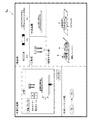
図35は、ロボットシステム10の具体的な全体構成図である。同図に示すロボットシステム10は、例えば自動車などの輸送機械、テレビ受像機などの電気機器の製造現場に設置されるものである。この製造現場には、ベルトコンベアやローラコンベアなどの搬送装置36が設置されており、該搬送装置36により、ロボットの作業スペースである作業台38に載置された未完成の自動車やテレビ受像機などの作業対象物34が一方向に搬送されている。搬送装置36の側には産業用多関節ロボット30A,30B,30Cが、上流側から下流側に向かって順に離間して配置されており、これらのロボット30A,30B,30Cはそれぞれ、部品の取り付けなどの事前に定められた作業を作業対象物34に対して施す。   FIG. 35 is a specific overall configuration diagram of the robot system 10. The robot system 10 shown in the figure is installed at a manufacturing site of electrical equipment such as a transport machine such as an automobile and a television receiver. At the manufacturing site, a conveyor device 36 such as a belt conveyor or a roller conveyor is installed. By the conveyor device 36, an unfinished automobile or television receiver placed on a work table 38 which is a work space of the robot. A work object 34 such as is conveyed in one direction. Industrial articulated robots 30A, 30B, and 30C are disposed on the transport device 36 side in order from the upstream side to the downstream side, and these robots 30A, 30B, and 30C are respectively attached with components. A predetermined work such as the above is performed on the work object 34.

ロボット30A,30B,30Cには、それらを制御するコンピュータであるロボットコントローラ20A,20B,20Cがそれぞれ接続されており、ロボットコントローラ20A,20B,20Cには、それぞれネットワーク装置18A,18B,18Cが接続されている。ネットワーク装置18A,18B,18Cは、いずれもロボットネットワーク40に接続されている。このロボットネットワーク40には、ロボットコントローラ20A,20B,20Cの動作を支援・管理するロボット管理コンピュータ100も接続されており、ロボットコントローラ20A,20B,20Cは、それぞれネットワーク装置18A,18B,18C及びロボットネットワーク40を介して、ロボット管理コンピュータ100と通信することができる。ここで、ネットワーク装置18A,18B,18C及びロボット管理コンピュータ100は、ロボットネットワーク40におけるアドレスその他のネットワーク識別子をそれぞれ記憶しており、ネットワーク識別子を用いて送信元及び送信先を互いに特定している。上記ロボット管理コンピュータ100は、本実施形態に係るロボット制御装置1とすることができる。   Robot controllers 20A, 20B, and 20C, which are computers for controlling them, are connected to the robots 30A, 30B, and 30C, respectively, and network devices 18A, 18B, and 18C are connected to the robot controllers 20A, 20B, and 20C, respectively. Has been. The network devices 18A, 18B, and 18C are all connected to the robot network 40. The robot network 40 is also connected to a robot management computer 100 that supports and manages the operations of the robot controllers 20A, 20B, and 20C. The robot controllers 20A, 20B, and 20C are respectively connected to the network devices 18A, 18B, and 18C and the robot. It is possible to communicate with the robot management computer 100 via the network 40. Here, the network devices 18A, 18B, 18C and the robot management computer 100 store addresses and other network identifiers in the robot network 40, respectively, and specify the transmission source and the transmission destination using the network identifier. The robot management computer 100 can be the robot control apparatus 1 according to the present embodiment.

搬送装置36は、作業台38をロボット30A,30B,30Cの設置位置の側にて停止させ、ロボット30A,30B,30Cによる作業が終了すると、それぞれの作業台38を下流側のロボットの設置位置の側まで移動させる。なお、ロボット30A,30B,30Cにより作業が終了した旨は、それぞれロボットコントローラ20A,20B,20Cから搬送装置36に通知されてよい。   The transfer device 36 stops the work table 38 on the side where the robots 30A, 30B, and 30C are installed, and when the work by the robots 30A, 30B, and 30C is completed, each work table 38 is placed on the downstream robot installation position. Move to the side. The robot controllers 20A, 20B, and 20C may notify the transfer device 36 that the work has been completed by the robots 30A, 30B, and 30C.

搬送装置36を挟んでロボット30A,30B,30Cの設置位置の反対側には、作業対象物IDリーダ32A,32B,32Cがそれぞれ配置されている。作業対象物34又はそれが載置される作業台38には、作業対象物34のID(識別情報)が、例えば1次元又は2次元バーコードなどの機械読み取りが可能な形態で付加されている。作業対象物34のIDは、例えば作業対象物34の最終的な又は暫定的なシリアル番号やロット番号であってよい。バーコードリーダーなどの作業対象物IDリーダ32A,32B,32Cは、作業対象物34又は作業台38に付加されたIDを読み取り、それを、生産管理ネットワーク42を介して生産管理コンピュータ200に通知する。すなわち、作業対象物IDリーダ32A,32B,32C及び生産管理コンピュータ200は生産管理ネットワーク42に接続されている。さらに、上述のロボット管理コンピュータ100(ロボット制御装置1)も生産管理ネットワーク42に接続されており、ロボット管理コンピュータ100と生産管理コンピュータ200とは通信可能となっている。   Work object ID readers 32A, 32B, and 32C are disposed on opposite sides of the installation positions of the robots 30A, 30B, and 30C with the transport device 36 interposed therebetween. An ID (identification information) of the work object 34 is added to the work object 34 or the work table 38 on which the work object 34 is placed in a machine-readable form such as a one-dimensional or two-dimensional barcode. . The ID of the work object 34 may be, for example, a final or provisional serial number or lot number of the work object 34. Work object ID readers 32A, 32B, and 32C such as a barcode reader read the ID added to the work object 34 or the work table 38 and notify the ID to the production management computer 200 via the production management network 42. . That is, the work object ID readers 32A, 32B, 32C and the production management computer 200 are connected to the production management network 42. Further, the above-described robot management computer 100 (robot control device 1) is also connected to the production management network 42 so that the robot management computer 100 and the production management computer 200 can communicate with each other.

また、ロボットシステム10では、例えばロボット30Aの導入時やロボット30Aの配置換えの時に、ロボット30Aを所期の設置位置に配置し、ロボットコントローラ20Aをネットワーク装置18Aに接続すると、ロボット管理コンピュータ100(ロボット制御装置1)がロボットコントローラ20Aで実行すべき動作制御プログラム(図34参照)を該ロボットコントローラ20Aに送信する。ロボットコントローラ20Aは、ロボット制御装置1から送信される動作制御プログラムを実行する。動作制御プログラムは、ロボット30Aのアーム先端に備えられたカメラや接触センサの出力、或いはタイマの出力に従って、どのような動きをロボット30Aのアーム各所に備えられたアクチュエータにさせるかが記述されている。この動作制御プログラムを実行することにより、ロボットコントローラ20Aから制御命令がロボット30Aに順次送信され、これによりロボット30Aの動作(例えば上記作業Aの動作)が制御される。これによりロボットコントローラ20Aはロボット30Aに所期の動作を確実に行わせることができる。ロボット30B,30Cについても同様である。産業用多関節ロボット30A,30B,30Cは動作制御プログラムの変更により、様々な作業を担うことができるため、ロボット30A,30B,30Cは、ある日は、製造現場のある場所である作業を行い、別の日は製造現場の別の場所で別の作業を行う、という使い方が可能である。本実施形態によれば、ロボット30A,30B,30Cの設置位置に応じて適切な動作制御プログラムをロボットコントローラ20A,20B,20Cに供給できるので、こうした使い方を促進できる。   Further, in the robot system 10, for example, when the robot 30A is introduced or when the robot 30A is rearranged, the robot 30A is arranged at a predetermined installation position, and the robot controller 20A is connected to the network device 18A. The robot control device 1) transmits an operation control program (see FIG. 34) to be executed by the robot controller 20A to the robot controller 20A. The robot controller 20A executes an operation control program transmitted from the robot control device 1. The motion control program describes what kind of movement is to be performed by the actuators provided in various portions of the arm of the robot 30A in accordance with the output of the camera or contact sensor provided at the arm tip of the robot 30A or the output of the timer. . By executing this operation control program, a control command is sequentially transmitted from the robot controller 20A to the robot 30A, whereby the operation of the robot 30A (for example, the operation of the operation A) is controlled. As a result, the robot controller 20A can reliably cause the robot 30A to perform the intended operation. The same applies to the robots 30B and 30C. Since the industrial articulated robots 30A, 30B, and 30C can perform various operations by changing the operation control program, the robots 30A, 30B, and 30C perform work at a certain site on a certain day. On another day, it is possible to use another work at another place on the manufacturing site. According to the present embodiment, an appropriate operation control program can be supplied to the robot controllers 20A, 20B, and 20C according to the installation positions of the robots 30A, 30B, and 30C.

なお、ロボットコントローラ20A,20B,20Cのそれぞれが、本実施形態に係るロボット制御装置1であってもよい。   Note that each of the robot controllers 20A, 20B, and 20C may be the robot control device 1 according to the present embodiment.

1 ロボット制御装置、10 ロボットシステム、30A,30B,30C ロボット、102 記憶部、104 制御部、106 通信部、107 表示部、5a 作業データ領域(作業テーブル)、5b テンプレートデータ領域、5c CADデータ領域(CADデータテーブル)、5d スキルデータ領域(作業パラメータテーブル)、5e ロボットデータ領域(ロボットデータテーブル)、5f 作業プログラム領域、5g 設定画面データ領域、5h 部品データ領域、5i 位置データ領域、5j 動作制御プログラム領域、11 操作受付部、12 作業取得部、13 作業工程取得部、14 部品情報取得部、15 工具情報取得部、16 パラメータ取得部、17 ロボット情報取得部、18 作業プログラム生成部、19 表示制御部、21 プログラム取得部、22 位置取得部、23 動作判定部、24 経路生成部、25 位置調整部、26 動作制御プログラム生成部、27 尤度算出部、19a 設定画面表示部、19b 部品欄設定部、19c 工具欄設定部、19d 環境モデル欄設定部、19e パラメータ設定部、19f 半製品欄設定部、19g 作業工程欄設定部、19h 作業シーケンス欄設定部、19i 作業シーケンス欄設定部、19j ログ欄設定部、19k 環境モデル欄設定部。   DESCRIPTION OF SYMBOLS 1 Robot control apparatus, 10 Robot system, 30A, 30B, 30C Robot, 102 Memory | storage part, 104 Control part, 106 Communication part, 107 Display part, 5a Work data area (work table), 5b Template data area, 5c CAD data area (CAD data table), 5d Skill data area (work parameter table), 5e Robot data area (robot data table), 5f Work program area, 5g Setting screen data area, 5h Parts data area, 5i Position data area, 5j Motion control Program area, 11 Operation accepting unit, 12 Work acquisition unit, 13 Work process acquisition unit, 14 Part information acquisition unit, 15 Tool information acquisition unit, 16 Parameter acquisition unit, 17 Robot information acquisition unit, 18 Work program generation unit, 19 Display Control unit , 21 Program acquisition unit, 22 Position acquisition unit, 23 Motion determination unit, 24 Path generation unit, 25 Position adjustment unit, 26 Operation control program generation unit, 27 Likelihood calculation unit, 19a Setting screen display unit, 19b Parts field setting unit 19c Tool column setting unit, 19d Environmental model column setting unit, 19e Parameter setting unit, 19f Semi-finished product column setting unit, 19g Work process column setting unit, 19h Work sequence column setting unit, 19i Work sequence column setting unit, 19j Log column Setting part, 19k environment model field setting part.

Claims (6)

ロボットが担う作業の内容を示す作業プログラムを該作業の情報に関連付けて記憶する記憶部と、
ロボットの座標位置を、該ロボットを識別するためのロボット識別情報に関連付けて記憶する記憶部と、
前記作業に含まれる複数の作業工程に応じた複数の設定画面を順に表示部に表示させる表示制御部と、
管理者により選択された作業に対応する前記作業プログラムと、該作業を担うロボットの前記座標位置の情報とに基づいて、該作業に対応する製造工程順で前後の作業工程間の該ロボットの動作経路を生成する経路生成部と、
各作業工程について、ロボットが動作を開始する開始点及びロボットが該動作により到達する到達点が、前記ロボットの座標位置に基づき算出された開始点及び到達点から所定範囲内にあるか否かを判定する動作範囲チェックと、前記ロボットが該作業工程に応じた動作により他の物体に干渉するか否かを判定する干渉チェックとを行う判定部と、
前記動作範囲チェック及び前記干渉チェックの少なくとも何れか一方で異常がある場合に、前記ロボットの座標位置を仮想空間内で調整する位置調整部と、
を含み、
前記位置調整部が、現在の作業工程について、前記ロボットの座標位置を仮想空間内で調整した場合、前記判定部は、既に前記動作範囲チェック及び前記干渉チェックを行った以前の作業工程と、前記現在の作業工程とについて、再度、前記動作範囲チェック及び前記干渉チェックを行う、
ことを特徴とするロボット制御装置。
A storage unit that stores a work program indicating the content of work performed by the robot in association with the work information;
A storage unit for storing the coordinate position of the robot in association with the robot identification information for identifying the robot;
A display control unit for sequentially displaying a plurality of setting screens according to a plurality of work steps included in the work on the display unit;
Based on the work program corresponding to the work selected by the administrator and the coordinate position information of the robot responsible for the work , the operation of the robot between the previous and subsequent work processes in the order of the manufacturing process corresponding to the work. A route generation unit for generating a route;
For each work process, whether or not the starting point at which the robot starts operation and the reaching point at which the robot reaches by the operation are within a predetermined range from the starting point and the reaching point calculated based on the coordinate position of the robot A determination unit that performs an operation range check to determine and an interference check to determine whether or not the robot interferes with another object by an operation according to the work process;
A position adjustment unit that adjusts the coordinate position of the robot in a virtual space when there is an abnormality in at least one of the operation range check and the interference check;
Including
When the position adjustment unit has adjusted the coordinate position of the robot in the virtual space for the current work process, the determination unit is the work process before the operation range check and the interference check, For the current work process, the operation range check and the interference check are performed again.
A robot controller characterized by that.
前記表示制御部は、管理者により選択された前記作業に対応する前記動作経路を生成するまでのログを前記設定画面に含める、ことを特徴とする請求項1に記載のロボット制御装置。   The robot control apparatus according to claim 1, wherein the display control unit includes a log until the operation path corresponding to the work selected by an administrator is generated in the setting screen. 前記表示制御部は、前記作業に含まれる作業工程を管理者に選択させるための選択画面を前記設定画面に含める、ことを特徴とする請求項1又は2に記載のロボット制御装置。   The robot control apparatus according to claim 1, wherein the display control unit includes a selection screen for allowing an administrator to select a work process included in the work in the setting screen. 前記表示制御部は、前記開始点及び前記到達点の少なくとも何れか一方が前記所定範囲内にない場合、又は、前記ロボットが前記他の物体に干渉する場合は、前記ロボットにおける前記所定範囲内を外れる部位又は前記他の物体に干渉する部位を、管理者が視認できるように前記表示部に表示させる、
ことを特徴とする請求項に記載のロボット制御装置。
When at least one of the start point and the arrival point is not within the predetermined range, or when the robot interferes with the other object, the display control unit moves within the predetermined range of the robot. Display on the display unit so that an administrator can visually recognize a part that detaches or interferes with the other object.
The robot control apparatus according to claim 1 .
前記表示制御部は、各作業工程に応じて、ロボット及び作業台を含むモデル画像を前記設定画面に含める、ことを特徴とする請求項1からの何れか1項に記載のロボット制御装置。 The display controller in accordance with the individual work processes, the robot control apparatus according Include model image on the setting screen, it claims 1, wherein in any one of 4, including a robot and a work surface. ロボットが担う作業の内容を示す作業プログラムを該作業の情報に関連付けて記憶する記憶部から、管理者により選択された作業に対応する前記作業プログラムを取得し、
ロボットの座標位置を、該ロボットを識別するためのロボット識別情報に関連付けて記憶する記憶部から、前記作業を担うロボットの前記座標位置の情報を取得し、
前記作業に含まれる複数の作業工程に応じた複数の設定画面を順に表示部に表示させ、
前記取得された前記作業プログラムと、前記取得された前記ロボットの座標位置の情報とに基づいて、該作業に対応する製造工程順で前後の作業工程間の該ロボットの動作経路を生成し、
各作業工程について、ロボットが動作を開始する開始点及びロボットが該動作により到達する到達点が、前記ロボットの座標位置に基づき算出された開始点及び到達点から所定範囲内にあるか否かを判定する動作範囲チェックと、前記ロボットが該作業工程に応じた動作により他の物体に干渉するか否かを判定する干渉チェックとを行い、
前記動作範囲チェック及び前記干渉チェックの少なくとも何れか一方で異常がある場合に、前記ロボットの座標位置を仮想空間内で調整し、
現在の作業工程について、前記ロボットの座標位置を仮想空間内で調整した場合、既に前記動作範囲チェック及び前記干渉チェックを行った以前の作業工程と、前記現在の作業工程とについて、再度、前記動作範囲チェック及び前記干渉チェックを行う、
ことを特徴とするロボット制御方法。
Obtaining the work program corresponding to the work selected by the administrator from a storage unit that stores the work program indicating the content of the work performed by the robot in association with the work information;
Obtaining information on the coordinate position of the robot responsible for the work from a storage unit that stores the coordinate position of the robot in association with the robot identification information for identifying the robot,
A plurality of setting screens corresponding to a plurality of work steps included in the work are sequentially displayed on the display unit,
Based on the acquired work program and the information on the acquired coordinate position of the robot, generate an operation path of the robot between the previous and subsequent work processes in the order of the manufacturing process corresponding to the work ,
For each work process, whether or not the starting point at which the robot starts operation and the reaching point at which the robot reaches by the operation are within a predetermined range from the starting point and the reaching point calculated based on the coordinate position of the robot Performing an operation range check to determine and an interference check to determine whether or not the robot interferes with other objects by the operation according to the work process,
When there is an abnormality in at least one of the operation range check and the interference check, the coordinate position of the robot is adjusted in a virtual space,
When the coordinate position of the robot is adjusted in the virtual space with respect to the current work process, the previous work process in which the operation range check and the interference check have already been performed and the current work process are performed again with respect to the operation. Perform range check and interference check,
A robot control method characterized by the above.
JP2013165817A 2013-08-09 2013-08-09 Robot control apparatus and robot control method Expired - Fee Related JP5850004B2 (en)

Priority Applications (4)

Application Number Priority Date Filing Date Title
JP2013165817A JP5850004B2 (en) 2013-08-09 2013-08-09 Robot control apparatus and robot control method
US14/453,579 US20150045949A1 (en) 2013-08-09 2014-08-06 Robot control apparatus and method for controlling robot
EP14180221.5A EP2835229A3 (en) 2013-08-09 2014-08-07 Robot control apparatus and method for controlling robot
CN201410392336.7A CN104339360A (en) 2013-08-09 2014-08-11 Robot control apparatus and method for controlling robot

Applications Claiming Priority (1)

Application Number Priority Date Filing Date Title
JP2013165817A JP5850004B2 (en) 2013-08-09 2013-08-09 Robot control apparatus and robot control method

Publications (2)

Publication Number Publication Date
JP2015033745A JP2015033745A (en) 2015-02-19
JP5850004B2 true JP5850004B2 (en) 2016-02-03

Family

ID=51292850

Family Applications (1)

Application Number Title Priority Date Filing Date
JP2013165817A Expired - Fee Related JP5850004B2 (en) 2013-08-09 2013-08-09 Robot control apparatus and robot control method

Country Status (4)

Country Link
US (1) US20150045949A1 (en)
EP (1) EP2835229A3 (en)
JP (1) JP5850004B2 (en)
CN (1) CN104339360A (en)

Families Citing this family (19)

* Cited by examiner, † Cited by third party
Publication number Priority date Publication date Assignee Title
WO2016132521A1 (en) * 2015-02-20 2016-08-25 株式会社日立製作所 Teaching data-generating device
JP6348141B2 (en) 2016-04-28 2018-06-27 ファナック株式会社 Robot control device displaying operation program including additional axis status
JP6380469B2 (en) * 2016-06-23 2018-08-29 カシオ計算機株式会社 Robot, robot control method and program
JP6653763B2 (en) * 2016-09-23 2020-02-26 ヤマハ発動機株式会社 Robot system, robot controller, robot control method, robot program
JP6894292B2 (en) * 2017-05-23 2021-06-30 Juki株式会社 Control system and mounting equipment
KR102499576B1 (en) * 2018-01-08 2023-02-15 삼성전자주식회사 Electric apparatus and method for control thereof
JP6973119B2 (en) * 2018-01-26 2021-11-24 セイコーエプソン株式会社 Robot control device and robot system
JP6969447B2 (en) * 2018-03-05 2021-11-24 日本電産株式会社 Robotic controller, record creation method and program
JP7087632B2 (en) * 2018-04-26 2022-06-21 セイコーエプソン株式会社 Robot control device
JP7131092B2 (en) * 2018-06-05 2022-09-06 オムロン株式会社 SIMULATION DEVICE, SIMULATION DEVICE CONTROL METHOD, AND SIMULATION DEVICE PROGRAM
JP6806757B2 (en) * 2018-11-16 2021-01-06 ファナック株式会社 Operation program creation device
CN109544796A (en) * 2018-11-30 2019-03-29 湖南金码智能设备制造有限公司 A kind of XY type is without screen automatic selling terminal and its cargo path position calibration method
JP7255210B2 (en) * 2019-01-31 2023-04-11 セイコーエプソン株式会社 Control device, robot system, and display method
JP7204587B2 (en) * 2019-06-17 2023-01-16 株式会社東芝 OBJECT HANDLING CONTROL DEVICE, OBJECT HANDLING DEVICE, OBJECT HANDLING METHOD AND OBJECT HANDLING PROGRAM
CN110450169B (en) * 2019-09-03 2023-12-22 中冶赛迪工程技术股份有限公司 Robot temperature measurement sampling control method and control system
CN115769161A (en) * 2020-07-07 2023-03-07 发那科株式会社 Robot control device
JP2022021462A (en) 2020-07-22 2022-02-03 セイコーエプソン株式会社 Teaching control method for robot, robot system, and computer program
US20240051123A1 (en) * 2021-04-09 2024-02-15 Fanuc Corporation Robot programming device
WO2024004101A1 (en) * 2022-06-29 2024-01-04 ファナック株式会社 Teaching device and computer program

Family Cites Families (31)

* Cited by examiner, † Cited by third party
Publication number Priority date Publication date Assignee Title
US4835730A (en) * 1987-02-27 1989-05-30 Adept Technology, Inc. Database driven robot programming system and method
JPS645779A (en) * 1987-06-29 1989-01-10 Fanuc Ltd Robot arrangement examination system
JP2738499B2 (en) * 1993-12-17 1998-04-08 株式会社アマダメトレックス Processing data creation system for welding finishing robot
US5930461A (en) * 1994-03-24 1999-07-27 Bernstein; Steven A. Method and apparatus for automated tissue assay
JP3037874B2 (en) * 1994-04-29 2000-05-08 インターナショナル・ビジネス・マシーンズ・コーポレイション Library management system and method
JP3529158B2 (en) * 1994-05-18 2004-05-24 ファナック株式会社 Robot operation programming method and programming device
JP3509413B2 (en) * 1995-10-30 2004-03-22 株式会社デンソー Motor control device
JPH09212229A (en) * 1996-01-30 1997-08-15 Komatsu Ltd Teaching device for robot
JPH10128687A (en) 1996-10-31 1998-05-19 Nippon Telegr & Teleph Corp <Ntt> Robot control method and device
US6107601A (en) * 1997-10-01 2000-08-22 Matsushita Electric Industrial Co., Ltd. Apparatus and method for controlling an arc welding robot
WO2000025185A1 (en) * 1998-10-27 2000-05-04 Irobotics, Inc. Robotic process planning using templates
JP2000135689A (en) * 1998-10-30 2000-05-16 Fanuc Ltd Image processor for robot
JP3673117B2 (en) * 1999-06-14 2005-07-20 和泉電気株式会社 Assembly apparatus and tray system therefor
US7849416B2 (en) * 2000-06-13 2010-12-07 National Instruments Corporation System and method for graphically creating a sequence of motion control, machine vision, and data acquisition (DAQ) operations
JP3639873B2 (en) * 2001-03-16 2005-04-20 川崎重工業株式会社 Robot control method and robot control system
US7215801B2 (en) * 2003-06-05 2007-05-08 General Electric Company Method, system and apparatus for processing radiographic images of scanned objects
EP1756684B1 (en) * 2004-06-15 2008-04-16 Abb Ab Method and system for off-line programming of multiple interacting robots
JP4951849B2 (en) * 2004-08-05 2012-06-13 富士通株式会社 Robot management system
EP1672548A1 (en) * 2004-12-20 2006-06-21 Dassault Systèmes Process and system for rendering an object in a view using a product lifecycle management database
JP4137909B2 (en) * 2005-04-13 2008-08-20 ファナック株式会社 Robot program correction device
JP4137927B2 (en) * 2005-08-04 2008-08-20 ファナック株式会社 Robot programming device
US7611452B2 (en) * 2005-09-30 2009-11-03 Accuray Incorporated Wizard and template for treatment planning
ATE414594T1 (en) * 2006-04-03 2008-12-15 Abb Research Ltd DEVICE AND METHOD FOR PATH GENERATION FOR AN INDUSTRIAL ROBOT
US7848835B2 (en) * 2006-06-02 2010-12-07 Cymer, Inc. High power laser flat panel workpiece treatment system controller
JP5103237B2 (en) * 2008-03-25 2012-12-19 株式会社神戸製鋼所 Robot operation margin calculation display method and apparatus
JP4759660B2 (en) * 2009-08-21 2011-08-31 パナソニック株式会社 Robot arm control device, method, program, integrated electronic circuit, and assembly robot
JP2011059801A (en) * 2009-09-07 2011-03-24 Mitsubishi Electric Corp Program creation/instruction device and method
US8965579B2 (en) * 2011-01-28 2015-02-24 Intouch Technologies Interfacing with a mobile telepresence robot
JP5855469B2 (en) * 2012-01-16 2016-02-09 株式会社日立製作所 Carry-in route planning system
US8965580B2 (en) * 2012-06-21 2015-02-24 Rethink Robotics, Inc. Training and operating industrial robots
US8868241B2 (en) * 2013-03-14 2014-10-21 GM Global Technology Operations LLC Robot task commander with extensible programming environment

Also Published As

Publication number Publication date
JP2015033745A (en) 2015-02-19
US20150045949A1 (en) 2015-02-12
CN104339360A (en) 2015-02-11
EP2835229A3 (en) 2016-06-08
EP2835229A2 (en) 2015-02-11

Similar Documents

Publication Publication Date Title
JP5850004B2 (en) Robot control apparatus and robot control method
JP5939213B2 (en) Robot control apparatus and robot control method
US11498214B2 (en) Teaching device, teaching method, and robot system
US20190243344A1 (en) Sorting support methods, sorting systems, and flatbed machine tools
JP6348097B2 (en) Work position and orientation calculation device and handling system
CN106163771B (en) Method and system for robot 3D printing
CN104936748B (en) Free-hand robot path teaching
CN105598987B (en) Determination of a gripping space for an object by means of a robot
US20080013825A1 (en) Simulation device of robot system
US11144041B2 (en) 3D visualizations of in-process products based on machine tool input
US11345026B2 (en) Robot program generation apparatus
US11231262B2 (en) Dynamically adapting operation of a coordinate measuring machine
KR20190037372A (en) Method and device for generating robot control program
KR20180017074A (en) Detection of the robot axial angles and selection of a robot by means of a camera
CN110914021A (en) Operating device with an operating device for carrying out at least one work step, and method and computer program
Rückert et al. Calibration of a modular assembly system for personalized and adaptive human robot collaboration
CN112805127A (en) Method and apparatus for creating robot control program
CN108145702B (en) Device for setting a boundary surface and method for setting a boundary surface
EP0830921A1 (en) A method for handling metal sheets in a working area comprising a machine tool and a robot
JP2022171749A (en) Processing control apparatus, processing control method, and program
JP7131447B2 (en) Information processing device, work selection method and work selection program
WO2017032407A1 (en) An industrial robot system and a method for programming an industrial robot
US20230249345A1 (en) System and method for sequencing assembly tasks
JP7362875B2 (en) Information provision device
JP7481591B1 (en) Apparatus and method for generating search model, apparatus and method for teaching work position, and control device

Legal Events

Date Code Title Description
A621 Written request for application examination

Free format text: JAPANESE INTERMEDIATE CODE: A621

Effective date: 20150115

A977 Report on retrieval

Free format text: JAPANESE INTERMEDIATE CODE: A971007

Effective date: 20150423

A131 Notification of reasons for refusal

Free format text: JAPANESE INTERMEDIATE CODE: A131

Effective date: 20150428

A521 Request for written amendment filed

Free format text: JAPANESE INTERMEDIATE CODE: A523

Effective date: 20150629

TRDD Decision of grant or rejection written
A01 Written decision to grant a patent or to grant a registration (utility model)

Free format text: JAPANESE INTERMEDIATE CODE: A01

Effective date: 20151104

A61 First payment of annual fees (during grant procedure)

Free format text: JAPANESE INTERMEDIATE CODE: A61

Effective date: 20151117

R150 Certificate of patent or registration of utility model

Ref document number: 5850004

Country of ref document: JP

Free format text: JAPANESE INTERMEDIATE CODE: R150

LAPS Cancellation because of no payment of annual fees