JP4137909B2 - Robot program correction device - Google Patents
Robot program correction device Download PDFInfo
- Publication number
- JP4137909B2 JP4137909B2 JP2005115841A JP2005115841A JP4137909B2 JP 4137909 B2 JP4137909 B2 JP 4137909B2 JP 2005115841 A JP2005115841 A JP 2005115841A JP 2005115841 A JP2005115841 A JP 2005115841A JP 4137909 B2 JP4137909 B2 JP 4137909B2
- Authority
- JP
- Japan
- Prior art keywords
- robot
- program
- line
- screen
- work location
- Prior art date
- Legal status (The legal status is an assumption and is not a legal conclusion. Google has not performed a legal analysis and makes no representation as to the accuracy of the status listed.)
- Expired - Fee Related
Links
Images


Classifications
-
- G—PHYSICS
- G05—CONTROLLING; REGULATING
- G05B—CONTROL OR REGULATING SYSTEMS IN GENERAL; FUNCTIONAL ELEMENTS OF SUCH SYSTEMS; MONITORING OR TESTING ARRANGEMENTS FOR SUCH SYSTEMS OR ELEMENTS
- G05B19/00—Programme-control systems
- G05B19/02—Programme-control systems electric
- G05B19/42—Recording and playback systems, i.e. in which the programme is recorded from a cycle of operations, e.g. the cycle of operations being manually controlled, after which this record is played back on the same machine
- G05B19/4202—Recording and playback systems, i.e. in which the programme is recorded from a cycle of operations, e.g. the cycle of operations being manually controlled, after which this record is played back on the same machine preparation of the programme medium using a drawing, a model
- G05B19/4207—Recording and playback systems, i.e. in which the programme is recorded from a cycle of operations, e.g. the cycle of operations being manually controlled, after which this record is played back on the same machine preparation of the programme medium using a drawing, a model in which a model is traced or scanned and corresponding data recorded
-
- B—PERFORMING OPERATIONS; TRANSPORTING
- B25—HAND TOOLS; PORTABLE POWER-DRIVEN TOOLS; MANIPULATORS
- B25J—MANIPULATORS; CHAMBERS PROVIDED WITH MANIPULATION DEVICES
- B25J9/00—Programme-controlled manipulators
- B25J9/16—Programme controls
- B25J9/1656—Programme controls characterised by programming, planning systems for manipulators
-
- G—PHYSICS
- G05—CONTROLLING; REGULATING
- G05B—CONTROL OR REGULATING SYSTEMS IN GENERAL; FUNCTIONAL ELEMENTS OF SUCH SYSTEMS; MONITORING OR TESTING ARRANGEMENTS FOR SUCH SYSTEMS OR ELEMENTS
- G05B19/00—Programme-control systems
- G05B19/02—Programme-control systems electric
- G05B19/18—Numerical control [NC], i.e. automatically operating machines, in particular machine tools, e.g. in a manufacturing environment, so as to execute positioning, movement or co-ordinated operations by means of programme data in numerical form
- G05B19/408—Numerical control [NC], i.e. automatically operating machines, in particular machine tools, e.g. in a manufacturing environment, so as to execute positioning, movement or co-ordinated operations by means of programme data in numerical form characterised by data handling or data format, e.g. reading, buffering or conversion of data
- G05B19/4083—Adapting programme, configuration
-
- G—PHYSICS
- G05—CONTROLLING; REGULATING
- G05B—CONTROL OR REGULATING SYSTEMS IN GENERAL; FUNCTIONAL ELEMENTS OF SUCH SYSTEMS; MONITORING OR TESTING ARRANGEMENTS FOR SUCH SYSTEMS OR ELEMENTS
- G05B2219/00—Program-control systems
- G05B2219/30—Nc systems
- G05B2219/36—Nc in input of data, input key till input tape
- G05B2219/36416—Adapt teached position as function of deviation 3-D, 2-D position of end effector, tool
-
- G—PHYSICS
- G05—CONTROLLING; REGULATING
- G05B—CONTROL OR REGULATING SYSTEMS IN GENERAL; FUNCTIONAL ELEMENTS OF SUCH SYSTEMS; MONITORING OR TESTING ARRANGEMENTS FOR SUCH SYSTEMS OR ELEMENTS
- G05B2219/00—Program-control systems
- G05B2219/30—Nc systems
- G05B2219/37—Measurements
- G05B2219/37079—Display probing result on drawing taken from cad data
-
- G—PHYSICS
- G05—CONTROLLING; REGULATING
- G05B—CONTROL OR REGULATING SYSTEMS IN GENERAL; FUNCTIONAL ELEMENTS OF SUCH SYSTEMS; MONITORING OR TESTING ARRANGEMENTS FOR SUCH SYSTEMS OR ELEMENTS
- G05B2219/00—Program-control systems
- G05B2219/30—Nc systems
- G05B2219/39—Robotics, robotics to robotics hand
- G05B2219/39012—Calibrate arm during scanning operation for identification of object
-
- Y—GENERAL TAGGING OF NEW TECHNOLOGICAL DEVELOPMENTS; GENERAL TAGGING OF CROSS-SECTIONAL TECHNOLOGIES SPANNING OVER SEVERAL SECTIONS OF THE IPC; TECHNICAL SUBJECTS COVERED BY FORMER USPC CROSS-REFERENCE ART COLLECTIONS [XRACs] AND DIGESTS
- Y02—TECHNOLOGIES OR APPLICATIONS FOR MITIGATION OR ADAPTATION AGAINST CLIMATE CHANGE
- Y02P—CLIMATE CHANGE MITIGATION TECHNOLOGIES IN THE PRODUCTION OR PROCESSING OF GOODS
- Y02P90/00—Enabling technologies with a potential contribution to greenhouse gas [GHG] emissions mitigation
- Y02P90/02—Total factory control, e.g. smart factories, flexible manufacturing systems [FMS] or integrated manufacturing systems [IMS]
Description
本発明はロボットプログラム補正装置に関し、特にオフラインで作成したロボット動作プログラムを現場で実際の作業箇所に合うように修正するロボットプログラム補正装置に関する。 The present invention relates to a robot program correction apparatus, and more particularly to a robot program correction apparatus that corrects a robot operation program created off-line to match an actual work location on site.
ロボットオフラインシステムでロボットの動作プログラムを作成し、これを現場に適用する際、オフライン上の世界と現場の世界にずれがあるため、オフラインで作成した動作プログラムをそのまま実行してもオフラインで計画したとおりの作業はできない。このため、このずれを補正する必要がある。 When creating a robot motion program using the robot offline system and applying it to the site, there is a gap between the offline world and the world of the site. You can't do the same. For this reason, it is necessary to correct this deviation.
従来は、オフラインで作成したプログラムを現場で実際の位置に合うようにロボットジョグを行い、教示修正を行っていた。ロボットジョグを行うとは、ロボットに作業位置を教示するためにロボットを動かすことをいう。 Conventionally, robots jog the program created off-line so that it matches the actual position on the site and correct the teaching. Performing robot jog refers to moving the robot to teach the robot the work position.
そして、オフラインで作成したプログラムを現場に適用する場合、画面上で定義した教示位置に対応する現場のワークの目標位置をロボットでタッチアップして、目標位置の点と実際にタッチした位置の点との差分で得られる4行×4列の単一差分行列を目標位置に右から掛け合わせることで目標位置をシフトすることにより、プログラムを補正し、ずれの発生した部分の教示修正を行っていた。 When applying the program created offline, the robot touches up the target position of the workpiece on the site corresponding to the teaching position defined on the screen, and the point of the target position and the point of the actually touched position. The program is corrected by correcting the program by correcting the program by shifting the target position by multiplying the target position from the right by a single difference matrix of 4 rows x 4 columns obtained by the difference between and the target position. It was.
従来の点の差により得られる単一差分行列のみを目標位置に右から掛け合わせることで目標位置をシフトする方法では、補正精度が良くない。このため、この修正をロボットを使ったジョグで繰り返す必要があり、補正後の修正に工数がかかるという課題がある。 In the conventional method of shifting the target position by multiplying the target position from the right only by the single difference matrix obtained by the difference of points, the correction accuracy is not good. For this reason, it is necessary to repeat this correction by jogging using a robot, and there is a problem that the correction after correction takes time.
本発明の目的は、上記従来技術における課題を解決し、ロボットの動作プログラムで定義されたロボットの動作経路と実際のロボットで現場のワークにタッチアップした点をもとに動作プログラムを修正する工程数を減少させるロボットプログラム補正装置を提供することにある。 The object of the present invention is to solve the above-mentioned problems in the prior art and to modify the operation program based on the robot operation path defined by the robot operation program and the point where the actual robot touched the work on the site. It is an object of the present invention to provide a robot program correction device that reduces the number.
上記の目的を達成するために、本発明の第1の態様により提供されるものは、ロボットとワークのそれぞれの3次元モデルを表示装置の画面上に同時に表示し、ロボットの動作プログラムを補正するロボットプログラム補正装置であって、タッチアップした点から算出された線及び面の少なくとも一方と画面上で指定した作業箇所の点から算出した線及び面の少なくとも一方との差分を算出する差分算出手段と、差分に基づいて補正量を算出し、ロボット動作プログラムを補正する補正手段とを備えることを特徴とするロボットプログラム補正装置である。 In order to achieve the above object, the first aspect of the present invention provides a three-dimensional model of a robot and a workpiece simultaneously on the screen of a display device, and corrects a robot operation program. A robot program correction device for calculating a difference between at least one of a line and a surface calculated from a touch-up point and at least one of a line and a surface calculated from a point of a work location designated on a screen And a correction means for calculating a correction amount based on the difference and correcting the robot operation program.
本発明の第2の態様によれば、第1の態様における「タッチアップした点から算出された線及び面の少なくとも一方と画面上で指定した作業箇所の点から算出した線及び面の少なくとも一方との差分を算出する差分算出手段」に替えて「タッチアップした点から算出された線及び面の少なくとも一方と検索された作業箇所の点から算出した線及び面の少なくとも一方との差分を算出する差分算出手段」を用いている。 According to a second aspect of the present invention, at least one of the lines and surfaces calculated in terms of "working position specified by at least one of the lines and surfaces, which are calculated from a point touched up and screen in the first embodiment Instead of “ difference calculation means for calculating the difference between ” and “ calculate the difference between at least one of the line and surface calculated from the touched-up point and at least one of the line and surface calculated from the point of the searched work location” The difference calculating means ”is used.
好ましくは、ロボットプログラム補正装置は、ロボット及びワークの前記画面上の配置位置に基づいてロボットの複数の動作プログラムを生成し記憶する動作プログラム記憶手段と、画面上に配置されたワークに対するロボットの作業個所を前記画面上で指定する作業箇所指定手段とを更に備えている。 Preferably, the robot program correction device generates an operation program storage means for generating and storing a plurality of operation programs for the robot based on the arrangement positions of the robot and the workpiece on the screen, and the robot operation on the workpiece arranged on the screen. Work location specifying means for specifying a location on the screen is further provided.
更に好ましくは、線又は面はスプライン曲線又はスプライン曲面である。 More preferably, the line or surface is a spline curve or a spline curved surface.
更に好ましくは、差分からロボットの機構モデルを補正することにより、動作プログラムの補正量を求める。 More preferably, the correction amount of the motion program is obtained by correcting the mechanism model of the robot from the difference.
更に好ましくは、ロボットの機構モデルはがD-Hパラメータである。 More preferably, the mechanism model of the robot is a D-H parameter.
オフラインで作成したプログラムを現場に適用する際、補正装置上の作業箇所からスプライン曲線又はスプライン曲面を作成し、また、現場で対応する点をタッチアップして、スプライン曲線又はスプライン曲面を作成する。この2つの曲線又は曲面を比較し、差分を求め、ロボットプログラム、および、ロボットのD-Hパラメータを補正することで、ロボットプログラムの補正精度が高くなり、現場でのプログラムの補正のための作業工数が短縮される。これにより、オフラインで作成したプログラムを現場に適用するときの作業が簡単化される。 When a program created off-line is applied to the work site, a spline curve or spline curved surface is created from the work location on the correction device, and a corresponding point is touched up on the work site to create a spline curve or spline curved surface. By comparing these two curves or curved surfaces, obtaining the difference, and correcting the robot program and the DH parameters of the robot, the correction accuracy of the robot program is improved, and the work man-hours for correcting the program on site are increased. Shortened. This simplifies work when applying the program created off-line to the site.
以下に本発明の実施の形態を説明する。全図を通じて同一参照番号は同一のものを示す。 Embodiments of the present invention will be described below. Throughout the drawings, the same reference numerals denote the same parts.
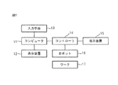
図1は本発明によるロボットプログラム補正装置を含むシステムの構成を示すブロック図である。同図において、11はパーソナルコンピュータ等のコンピュータ、12はコンピュータ11に接続された表示装置、13はコンピュータに接続された入力手段であって、キーボートやマウス等により実現される。14はコンピュータ11格納されているロボット動作プログラムによりロボット16の動作を制御するコントローラ、15はコントローラ14を介してロボットの作業位置を教示したり、コンピュータ11にロボット動作プログラムをインストールしたりするための教示装置、16はコントローラ15により制御されるロボット、17はロボット16により加工されたり移動されたりするワークである。
FIG. 1 is a block diagram showing the configuration of a system including a robot program correction apparatus according to the present invention. In the figure, 11 is a computer such as a personal computer, 12 is a display device connected to the
本発明によるロボットプログラム補正装置はコンピュータ11により実現される。
The robot program correction apparatus according to the present invention is realized by the
表示装置12の画面上にはロボット16、ワーク17及び必要に応じて周辺機器(図示せず)の画像が3次元データとして同時に表示される。
On the screen of the
教示装置15は表示装置12の画面上に表示されたロボットの画像又は実際のロボットを操作者が見ながらロボット16の作業箇所を指定したりロボット16の動きを指定したりするために用いられる携帯端末である。
The
図2は本発明の実施例1によるロボットプログラム補正装置の構成を示す機能ブロック図である。同図において、20は表示装置12に接続されたロボットプログラム補正装置である。ロボットプログラム補正装置20はパーソナルコンピュータ11等により実現される。ロボットプログラム補正装置20は、ロボットとワークのそれぞれの3次元モデルを表示装置12の画面上に同時に表示し、ロボットの動作プログラムを補正するものである。ロボットプログラム補正装置20は、画面上で指定された作業箇所に対応した実際のワーク上の位置を実際のロボットによりタッチアップすることにより実際のワーク上の位置を複数の点として記憶するタッチアップ位置記憶手段21と、タッチアップした複数の点に基づいて、線及び面の少なくとも一方を算出するタッチアップ線又はタッチアップ面算出手段22と、画面上に表示されているワーク上の作業箇所の位置情報を複数の点として格納する作業箇所格納手段23と、作業箇所格納手段内23の複数の点に基づいて、ロボット動作プログラムを検索するロボット動作プログラム検索手段24と、ロボット動作プログラムが示す複数の作業箇所に基づいて、線及び面の少なくとも一方を算出する作業箇所線又は面算出手段25と、タッチアップした点から算出された線及び面の少なくとも一方と前記画面上で指定した作業箇所の点から算出した線及び面の少なくとも一方との差分を算出する差分算出手段26と、その差分に基づいて補正量を算出し、ロボット動作プログラムを補正する補正手段27とを備えている。
FIG. 2 is a functional block diagram showing the configuration of the robot program correction apparatus according to the first embodiment of the present invention. In the figure,
図3は本発明の実施例2によるロボットプログラム補正装置の構成を示す機能ブロック図である。同図において、図2と異なるところは、図2における作業個所格納手段23が画面上に表示されているワークの画面上の作業箇所の位置情報を複数の点として取得するのに対して、図3においては、実際のロボットに対するタッチアップ位置からこれに関連するロボット動作プログラム及び作業箇所を検索する手段31と、検索されたロボット動作プログラム及び作業位置に基づいて、作業箇所の線及び面の少なくとも一方を算出する作業箇所線又は面算出手段32とを備えていることである。 FIG. 3 is a functional block diagram showing the configuration of the robot program correction apparatus according to the second embodiment of the present invention. 2 is different from FIG. 2 in that the work location storage means 23 in FIG. 2 acquires the position information of the work location on the screen of the work displayed on the screen as a plurality of points. 3, at least one of the line and the surface of the work location based on the retrieved robot operation program and the work position based on the retrieved robot operation program and the work location. And a work location line or surface calculation means 32 for calculating one of them.
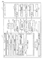
図4は実施例1及び実施例2によるロボットプログラム補正装置とロボットコントローラ14の構成を具体的に示すブロック図である。同図において、プログラム補正装置40はコンピュータ11に含まれている。プログラム補正装置40は、レイアウト作成部401と、ワークデータ読込部402と、動作プログラム作成部403と、実施例1においては作業箇所から動作プログラムを検索する動作プログラム検索部404又は実施例2においてはタッチアップ点からロボット動作プログラムと作業箇所を検索する検索部405と、プログラム補正部406とを備えている。
FIG. 4 is a block diagram specifically illustrating the configuration of the robot program correction apparatus and the
コンピュータ11は更に、ワーク17に関するデータを格納するワークデータ記憶部407と、ロボットプログラム計測箇所記憶部408と、作業箇所記憶部409と、タッチアップ位置記憶部410と、補正後のロボットプログラム記憶部411と、補正ソフト基本機能部412とを備えている。プログラム補正装置40は補正ソフト基本機能部412にプラグインされる。
The
ロボットコントローラ14は、ロボットプログラム計測箇所記憶部408に記憶されている計測箇所のロボットプログラムを読み込むロボットプログラム読込部413と、読み込んだプログラムに従ってロボットジョグを行うジョグ機能部414と、タッチアップしたワークの位置をタッチアップ位置記憶部410に教示するタッチアップ機能部415と、補正後のロボットプログラムを読み込むロボットプログラム読込部416と、読み込んだ補正後のプログラムを実行する実行部417とを備えている。
The
次に図2及び図3に示した機能ブロック図と図4に示した具体的構成との関係を説明する。 Next, the relationship between the functional block diagram shown in FIGS. 2 and 3 and the specific configuration shown in FIG. 4 will be described.
図2及び図3のタッチアップ位置記憶手段21は図4のタッチアップ位置記憶部410に相当する。図2の作業箇所格納手段23は図4の作業箇所格納部409に相当する。図2のロボット動作プログラム検索手段24は図4の動作プログラム検索部404に相当する。図3のロボット動作プログラム及び作業箇所検索手段31は図4の検索部405に相当する。図2のタッチアップ線又は面算出手段22及び差分算出手段26、差分算出手段26、補正手段27、図3の作業箇所線又は面算出手段32、差分算出手段33及び補正手段34は図4のプログラム補正部406に相当する。
2 and 3 corresponds to the touch-up
図5は図4に示したロボットプログラム補正装置の実施例1による動作を説明するフローチャートである。同図において、ステップS51にて、レイアウト作成部401は表示装置12の画面上で、ロボット16、ワーク17及び必要に応じて周辺機器(図示省略)の3次元データを配置することによりレイアウト作成を行う。レイアウトされたワークの画像に関係するワークデータはワークデータ記憶部407からワークデータ読込部402に読み込まれる。
FIG. 5 is a flowchart for explaining the operation of the robot program correcting apparatus shown in FIG. 4 according to the first embodiment. In the figure, in step S51, the
次にステップS52にて、表示装置12の画面上にレイアウトされたロボットやワークの画像に対応する複数の動作プログラムを周知の手法で作成する。
Next, in step S52, a plurality of operation programs corresponding to the robot and workpiece images laid out on the screen of the
次にステップS53にて、操作者は教示装置15を用いて表示装置12の画面上に表示されているワークやロボットの画像の上で作業個所を指定する。この指定はマウスを用いてカーソルを作業個所に移動させてクリックするとか、画面上に全作業個所を表示させてその中から選択させる等、様々な方法で実現できる。指定された作業個所は作業個所格納手段23(作業箇所記憶部409)に格納される。
Next, in step S <b> 53, the operator uses the
次にステップS54にて、ステップS53にて指定された作業個所から最も近いロボット動作プログラムを、ステップS52にて作成したロボット動作プログラムから検索する。 In step S54, the robot operation program closest to the work location specified in step S53 is searched from the robot operation program created in step S52.
次にステップS55にて、実際のロボット16により実際のワーク17の、上記指定された作業個所に対応する個所をタッチアップし、タッチアップされた個所は実ワーク位置記憶手段21(タッチアップ位置記憶部410)に格納される。
Next, in step S55, the
最後にステップS56にて、作業個所格納手段23(作業箇所記憶部409)に格納されている画面上の作業個所と、タッチアップ位置記憶手段21(タッチアップ位置記憶部410)に格納されているタッチアップ点との線又は面を、作業個所線又は面算出手段25及びタッチアップ線又は面算出手段22により算出し、差分算出手段26によりそれらの差分を算出し、その差分に基づいてステップS54にて検索されたロボット動作プログラムを補正する。 Finally, in step S56, the work location on the screen stored in the work location storage means 23 (work location storage section 409) and the touch-up position storage means 21 (touch-up position storage section 410) are stored. A line or surface with the touch-up point is calculated by the work location line / surface calculating means 25 and the touch-up line or surface calculating means 22, and the difference calculating means 26 calculates the difference between them. Based on the difference, step S54 is performed. Correct the robot operation program searched in.
図6は図4に示したロボットプログラム補正装置の実施例2による動作を説明するフローチャートである。同図において、図5と異なるところは、図5においてはステップS54で画面上の作業個所からロボット動作プログラムを検索するのに対して、図6においては、ステップS65にて実際のロボットに対するタッチアップ点に最も近いロボット動作プログラム及び作業個所を検索する点であり、他のステップは図5と同じであるのでここでは説明を省略する。 FIG. 6 is a flowchart for explaining the operation of the robot program correcting apparatus shown in FIG. 4 according to the second embodiment. 5 differs from FIG. 5 in that, in FIG. 5, the robot operation program is searched from the work location on the screen in step S54, whereas in FIG. 6, the actual robot is touched up in step S65. The robot operation program and work location closest to the point are searched, and the other steps are the same as in FIG.
図7は表示装置12の画面上に表示されている作業面Psとこれに対応する実際のロボット16の作業面(タッチアップ面)Ptを示す図である。図示のように、一般に画面上の作業面Psとタッチアップ面PtとはベクトルDだけずれている。まる印は教示点を示しており、画面上で指定した教示点と実際のロボットの教示点とがずれているので、このずれを補償するためにロボット動作プログラムを上記の手段により補正する。
FIG. 7 is a diagram showing the work surface Ps displayed on the screen of the
次にロボット動作プログラムの補正の具体的な方法を説明する。 Next, a specific method for correcting the robot operation program will be described.
まず、画面上の作業箇所Qsjから、行列Nijを用いて下記の式で表されるようにしてスプライン曲面になるように作業面Ps(u,w)を算出する。ここで、Qsj中の添え字sは作業面の3次元表面位置surface(表面)を表し、jは作業面上の作業点のインデックスである。また、u及びwは0から1までの値を取る媒介変数である。 First, the work surface Ps (u, w) is calculated from the work location Qsj on the screen so as to be a spline curved surface as represented by the following equation using the matrix Nij. Here, the subscript s in Qsj represents the three-dimensional surface position surface (surface) of the work surface, and j is the index of the work point on the work surface. U and w are parameters that take values from 0 to 1.
Ps(u,w)=ΣNij(t) Qsj Ps (u, w) = ΣNij (t) Qsj
同様にタッチアップ点Qtjから、スプライン曲面になるようにタッチアップ面Pt(u,w)を算出する。 Similarly, the touch-up surface Pt (u, w) is calculated from the touch-up point Qtj so as to be a spline curved surface.
次に差分単位法線ベクトルe(u,w)とオフセット距離dを以下の式により算出する。 Next, the difference unit normal vector e (u, w) and the offset distance d are calculated by the following equations.
2面の差分D(u,w)は
D(u,w) =Ps(u,w)-Pt(u,w)
e(u,w) = D(u,w)/|D(u,w)|
d=|D(u,w)|
The difference D (u, w) between the two surfaces is
D (u, w) = Ps (u, w) -Pt (u, w)
e (u, w) = D (u, w) / | D (u, w) |
d = | D (u, w) |
次に画面上で作成した、ロボット動作プログラムの教示点Pr(i)を上記差分ベクトルに従って、以下のように補正する。 Next, the teaching point Pr (i) of the robot operation program created on the screen is corrected as follows according to the difference vector.
変換行列M=(n, o, a, D(u,w))
n=(1, 0, 0)
o=(0, 1, 0)
a=(0, 0, 1)
ここで、n,o,aはロボット工学におけるリンク座標系で通常用いられるアームの手先の姿勢を表すパラメータであってそれぞれ、ノーマル、オリエント、アプローチを表す。また、D(u,w)は上記の式で得られた差分ベクトルであってロケーションを表す。
Transformation matrix M = (n, o, a, D (u, w))
n = (1, 0, 0)
o = (0, 1, 0)
a = (0, 0, 1)
Here, n, o, and a are parameters that represent the posture of the hand of the arm normally used in the link coordinate system in robot engineering, and represent normal, orientation, and approach, respectively. D (u, w) is a difference vector obtained by the above formula and represents a location.
変換後の教示点Pn(i)は実施例1によれば
Pn(i) = M Pr(i)
となり、実施例2によれば
Pn(i) = X Pr(i)
となる。ここで行列Xは、
According to the first embodiment, the teaching point Pn (i) after conversion is
Pn (i) = M Pr (i)
And according to Example 2,
Pn (i) = X Pr (i)
It becomes. Where matrix X is

図8は上記補正により変更されたロボットの位置とワークの位置の関係を示す図である。補正前のロボットの位置はベクトルR、補正前のワークの位置はベクトルWとし、画面上の作業面Psとタッチアップ面PtとはベクトルDだけずれているとすると、補正後のワークの位置ベクトルWdは図示のようにベクトルWとベクトルDとの内積W.Dとなる。 FIG. 8 is a diagram showing the relationship between the position of the robot and the position of the work changed by the correction. If the position of the robot before correction is a vector R, the position of the workpiece before correction is a vector W, and the work surface Ps and touch-up surface Pt on the screen are shifted by a vector D, the position vector of the corrected workpiece Wd is an inner product W. of vector W and vector D as shown in the figure. D.
次にロボットプログラム補正装置によるロボットのD-Hパラメータの変更について説明する。D-HパラメータとはDenavit-Hartenbergの方法により設定される周知のパラメータである。 Next, the change of the DH parameter of the robot by the robot program correction device will be described. The D-H parameter is a well-known parameter set by the Denavit-Hartenberg method.
ロボットのTCP(Tool Center Point)の位置姿勢は各リンクの行列の掛け算で表される。TCPとはロボットの先端部の位置のことで3次元座標で表される。 The position and orientation of the robot's TCP (Tool Center Point) is represented by multiplication of the matrix of each link. TCP is the position of the tip of the robot and is expressed in 3D coordinates.
実施例1において、リンクが6軸あり、それぞれの軸を表す行列をA1,A2,A3,A4,A5,A6とし、ツールの行列をTとすると、TCPは以下のようになる。 In the first embodiment, there are 6 links, and the matrix representing each axis is A1, A2, A3, A4, A5 , A6, and the tool matrix is T, TCP is as follows.
TCP=A1A2A3A4A5A6T TCP = A1A2A3A4A5A6T
ワークのレイアウト補正に伴い、同時にワークに依存する作業箇所も自動的に補正される。また、同時にロボットプログラム補正装置上のロボットの動作プログラムの教示点も補正する。 Along with the work layout correction, the work location depending on the work is also automatically corrected. At the same time, the teaching point of the robot operation program on the robot program correction device is also corrected.
ロボットプログラム補正装置上(画面上)の教示点とタッチアップ点をさらに比較し、その差分を補正装置上のロボットのD-Hパラメータのリンクの位置、姿勢(θ、α)に加算する。 The teaching point on the robot program correction device (on the screen) is further compared with the touch-up point, and the difference is added to the position and orientation (θ, α) of the D-H parameter link of the robot on the correction device.
A =(n, o, a, l)
n = (cθ, sθ, 0, 0)
o = (-cαsθ, sαcθ, sα, 0)
a = (sαsθ, -sαcθ, cα, 0)
l = (Acθ, Asθ, sα, 1)
ここで、lはロケーションを表す。
A = (n, o, a, l)
n = (cθ, sθ, 0, 0)
o = (-cαsθ, sαcθ, sα, 0)
a = (sαsθ, -sαcθ, cα, 0)
l = (Acθ, Asθ, sα, 1)
Here, l represents a location.
タッチアップ点Ti(x, y, z, w, p, r) I=1,nについて
ここでw,p,rは座標系の姿勢を表す角として知られているヨー、ピッチ、ロー角を表す。
Touch-up point Ti (x, y, z, w, p, r) for I = 1, n where w, p, r are the yaw, pitch, and low angles known as angles representing the orientation of the coordinate system. To express.
Ti= A1iA2iA3iA4iA5iA6iT
I=1,n
の連立方程式を解き、
θt、αtを算出する。
Ti = A1iA2iA3iA4iA5iA6iT
I = 1, n
Solve the simultaneous equations of
θt and αt are calculated.
画面上の作業箇所に対しても同様にθs、αsを求める。 Similarly, θs and αs are obtained for the work location on the screen.
差分θd=θt-θs、θd=αt-αs
これをD-Hパラメータの対応する要素に加算し、D-Hパラメータを補正する。このパラメータが次回から使用される。
Difference θd = θt-θs, θd = αt-αs
This is added to the corresponding element of the DH parameter to correct the DH parameter. This parameter will be used from the next time.
次に実施例2におけるタッチアップ点に近いロボット動作プログラム、作業箇所の検索について説明する。 Next, the robot operation program near the touch-up point and the search for the work location in the second embodiment will be described.
まず、タッチアップ点列からこの点列を繋ぐスプライン曲線を作成する。 First, a spline curve connecting the point sequences from the touch-up point sequence is created.
同様にロボット動作プログラムの教示点列からこの点列を繋ぐスプライン曲線を作成する。 Similarly, a spline curve connecting the point sequences is created from the teaching point sequence of the robot operation program.
タッチアップ点Ti(xi, yi, zi, wi, pi, ri)
教示点列Ki(xi, yi, zi, wi, pi, ri)
のスプライン曲線はそれぞれ
Pti(t)=N0(t)Ti-1+N1(t)Ti+ N2(t)Ti+1+N3(t)Ti+2
Pki(t)=N0(t)Ki-1+N1(t)Ki+ N2(t)Ki+1+N3(t)Ki+2
となる。
Touch-up point Ti (xi, yi, zi, wi, pi, ri)
Teaching point sequence Ki (xi, yi, zi, wi, pi, ri)
Each spline curve is
Pti (t) = N0 (t) Ti-1 + N1 (t) Ti + N2 (t) Ti + 1 + N3 (t) Ti + 2
Pki (t) = N0 (t) Ki-1 + N1 (t) Ki + N2 (t) Ki + 1 + N3 (t) Ki + 2
It becomes.
この差分をもとめ、これが最小となるロボット動作プログラムを選択する。また、これに対応した作業箇所を選択する。 This difference is obtained and a robot operation program that minimizes the difference is selected. Also, a work location corresponding to this is selected.
以上の説明から明らかなように、本発明により以下の効果が得られる。 As is clear from the above description, the following effects can be obtained by the present invention.
(1)オフラインで作成したプログラムを現場に適用するときの操作を簡単にすることが出来る。 (1) It is possible to simplify the operation when applying the program created offline to the site.
(2)オフラインで作成したプログラムを現場に適用するときの工数を短縮することが出来る。 (2) The number of man-hours when applying a program created offline can be reduced.
12 表示装置
21 タッチアップ位置記憶手段
22 タッチアップ線又は面算出手段
23 作業箇所格納手段
24 ロボット動作プログラム検索手段
25 作業箇所線又は面算出手段
26 差分算出手段
27 補正手段
31 ロボット動作プログラム及び作業箇所検索手段
32 作業箇所線又は面算出手段
33 差分算出手段
34 補正手段
DESCRIPTION OF
Claims (5)
前記画面上で指定された作業箇所に対応した実際のワーク上の位置を実際のロボットによりタッチアップすることにより実際のワーク上の位置を複数の点として記憶するタッチアップ位置記憶手段と、
前記タッチアップした複数の点に基づいて、線及び面の少なくとも一方を算出するタッチアップ線又はタッチアップ面算出手段と、
前記画面上に表示されているワーク上の作業箇所の位置情報を複数の点として格納する作業箇所格納手段と、
前記作業箇所格納手段内の複数の点に基づいて、ロボット動作プログラムを検索するロボット動作プログラム検索手段と、
前記ロボット動作プログラムが示す複数の作業箇所に基づいて、線及び面の少なくとも一方を算出する作業箇所線又は面算出手段と、
前記タッチアップした点から算出された線及び面の少なくとも一方と前記画面上で指定した作業箇所の点から算出した線及び面の少なくとも一方との差分を算出する差分算出手段と、
前記差分に基づいて補正量を算出し、前記ロボット動作プログラムを補正する補正手段とを備え、
前記補正手段は、前記差分からロボットの機構モデルを補正することにより、動作プログラムの補正量を求めることを特徴とするロボットプログラム補正装置。 A robot program correcting device that simultaneously displays a three-dimensional model of each of a robot and a workpiece on a screen of a display device, and corrects the operation program of the robot,
Touch-up position storage means for storing the position on the actual workpiece as a plurality of points by touching up the actual position on the workpiece corresponding to the work location designated on the screen by an actual robot;
Touch-up line or touch-up surface calculating means for calculating at least one of a line and a surface based on the plurality of touched-up points;
Work location storage means for storing the position information of the work location on the workpiece displayed on the screen as a plurality of points;
Robot operation program search means for searching for a robot operation program based on a plurality of points in the work location storage means;
Work location line or surface calculation means for calculating at least one of a line and a surface based on a plurality of work locations indicated by the robot operation program;
A difference calculating means for calculating a difference between at least one of a line and a surface calculated from the touched-up point and at least one of a line and a surface calculated from a point of the work location designated on the screen;
A correction unit that calculates a correction amount based on the difference and corrects the robot operation program ;
The robot program correction apparatus according to claim 1, wherein the correction means determines a correction amount of the operation program by correcting a mechanism model of the robot from the difference .
前記画面上で指定された作業箇所に対応した実際のワーク上の位置を実際のロボットによりタッチアップすることにより実際のワーク上の位置を複数の点として記憶するタッチアップ位置記憶手段と、 Touch-up position storage means for storing the position on the actual workpiece as a plurality of points by touching up the actual position on the workpiece corresponding to the work location designated on the screen by an actual robot;
前記タッチアップ位置からこれに関連するロボット動作プログラム及び作業箇所を検索する手段と、Means for retrieving a robot operation program and a work location related thereto from the touch-up position;
前記タッチアップした複数の点に基づいて、線及び面の少なくとも一方を算出するタッチアップ線又はタッチアップ面算出手段と、Touch-up line or touch-up surface calculating means for calculating at least one of a line and a surface based on the plurality of touched-up points;
前記検索された作業箇所の複数の点に基づいて、線及び面の少なくとも一方を算出する作業箇所線または面算出手段と、A work part line or surface calculating means for calculating at least one of a line and a surface based on the plurality of points of the searched work parts;
前記タッチアップした点から算出された線及び面の少なくとも一方と前記検索された作業箇所の点から算出した線及び面の少なくとも一方との差分を算出する差分算出手段と、A difference calculating means for calculating a difference between at least one of a line and a surface calculated from the touched-up point and at least one of a line and a surface calculated from the point of the searched work location;
前記差分に基づいて補正量を算出し、前記ロボット動作プログラムを補正する補正手段とを備え、 A correction unit that calculates a correction amount based on the difference and corrects the robot operation program;
前記補正手段は、前記差分からロボットの機構モデルを補正することにより、動作プログラムの補正量を求めることを特徴とするロボットプログラム補正装置。The robot program correction apparatus according to claim 1, wherein the correction means determines a correction amount of the operation program by correcting a mechanism model of the robot from the difference.
前記画面上に配置された前記ワークに対する前記ロボットの作業個所を前記画面上で指定する作業箇所指定手段とを更に備えることを特徴とする請求項1又は2に記載のロボットプログラム補正装置。 An operation program storage means for generating and storing a plurality of operation programs of the robot based on the arrangement positions of the robot and the workpiece on the screen;
The robot program correction apparatus according to claim 1, further comprising: a work location designation unit that designates a work location of the robot for the workpiece arranged on the screen on the screen .
Priority Applications (4)
| Application Number | Priority Date | Filing Date | Title |
|---|---|---|---|
| JP2005115841A JP4137909B2 (en) | 2005-04-13 | 2005-04-13 | Robot program correction device |
| CNB2006100655456A CN100476655C (en) | 2005-04-13 | 2006-03-20 | Robot program correcting apparatus |
| EP06006837A EP1712969B1 (en) | 2005-04-13 | 2006-03-31 | Robot program correcting apparatus |
| US11/279,348 US7643905B2 (en) | 2005-04-13 | 2007-04-23 | Robot program correcting apparatus |
Applications Claiming Priority (1)
| Application Number | Priority Date | Filing Date | Title |
|---|---|---|---|
| JP2005115841A JP4137909B2 (en) | 2005-04-13 | 2005-04-13 | Robot program correction device |
Publications (3)
| Publication Number | Publication Date |
|---|---|
| JP2006293826A JP2006293826A (en) | 2006-10-26 |
| JP2006293826A5 JP2006293826A5 (en) | 2007-08-02 |
| JP4137909B2 true JP4137909B2 (en) | 2008-08-20 |
Family
ID=36694355
Family Applications (1)
| Application Number | Title | Priority Date | Filing Date |
|---|---|---|---|
| JP2005115841A Expired - Fee Related JP4137909B2 (en) | 2005-04-13 | 2005-04-13 | Robot program correction device |
Country Status (4)
| Country | Link |
|---|---|
| US (1) | US7643905B2 (en) |
| EP (1) | EP1712969B1 (en) |
| JP (1) | JP4137909B2 (en) |
| CN (1) | CN100476655C (en) |
Families Citing this family (18)
| Publication number | Priority date | Publication date | Assignee | Title |
|---|---|---|---|---|
| JP4174517B2 (en) | 2006-03-13 | 2008-11-05 | ファナック株式会社 | Teaching position correcting device and teaching position correcting method |
| DE102006022483A1 (en) * | 2006-05-13 | 2007-11-29 | Kuka Roboter Gmbh | Method and device for displaying a robot path for supporting a change of location of a support point |
| US7979315B2 (en) * | 2007-03-14 | 2011-07-12 | Microsoft Corporation | Virtual features of physical items |
| EP2468451A3 (en) * | 2007-04-26 | 2013-09-04 | Adept Technology Inc. | Vacuum gripping apparatus |
| JP5386921B2 (en) * | 2008-10-09 | 2014-01-15 | セイコーエプソン株式会社 | Industrial robot position teaching apparatus, operation program creating apparatus, industrial robot position teaching method and program |
| DE102008052592A1 (en) * | 2008-10-21 | 2010-04-22 | Trumpf Werkzeugmaschinen Gmbh + Co. Kg | Apparatus and method for controlling a processing plant |
| JP2010152550A (en) * | 2008-12-24 | 2010-07-08 | Canon Inc | Work apparatus and method for calibrating the same |
| JP5282014B2 (en) * | 2009-11-18 | 2013-09-04 | 本田技研工業株式会社 | Teaching line correction device, teaching line correction method, and program thereof |
| DE102010047641B4 (en) * | 2010-10-06 | 2022-06-15 | Kuka Roboter Gmbh | control of a robot |
| DE102011086941B4 (en) * | 2011-11-23 | 2016-01-21 | Kuka Roboter Gmbh | industrial robots |
| JP5850004B2 (en) * | 2013-08-09 | 2016-02-03 | 株式会社安川電機 | Robot control apparatus and robot control method |
| CA2977915C (en) * | 2015-02-25 | 2018-09-11 | Honda Motor Co., Ltd. | Spot position correcting method and apparatus |
| GB201509341D0 (en) | 2015-05-29 | 2015-07-15 | Cambridge Medical Robotics Ltd | Characterising robot environments |
| US9718192B2 (en) * | 2015-06-24 | 2017-08-01 | National Taipei University Of Technology | System for automatically and precisely positioning robotic arm and method thereof |
| JP6860843B2 (en) * | 2017-02-20 | 2021-04-21 | 株式会社安川電機 | Robot system, robot control device, and robot control method |
| US10307908B2 (en) | 2017-04-07 | 2019-06-04 | X Development Llc | Methods and systems for establishing and maintaining a pre-build relationship |
| JP6626065B2 (en) * | 2017-10-31 | 2019-12-25 | ファナック株式会社 | Robot teaching device that warns or corrects the displacement of the teaching point or teaching line |
| JP7305951B2 (en) * | 2018-12-14 | 2023-07-11 | ニデック株式会社 | CALIBRATION DEVICE AND CALIBRATION METHOD |
Family Cites Families (15)
| Publication number | Priority date | Publication date | Assignee | Title |
|---|---|---|---|---|
| US4901218A (en) * | 1987-08-12 | 1990-02-13 | Renishaw Controls Limited | Communications adaptor for automated factory system |
| JP2708458B2 (en) * | 1988-04-01 | 1998-02-04 | 株式会社豊田中央研究所 | Copy control robot |
| JPH0519840A (en) * | 1991-07-12 | 1993-01-29 | Fanuc Ltd | Off-line verification system |
| JPH09269808A (en) * | 1996-03-29 | 1997-10-14 | Fanuc Ltd | Cnc data correcting method |
| SE0001312D0 (en) * | 2000-04-10 | 2000-04-10 | Abb Ab | Industrial robot |
| EP1302829B1 (en) * | 2001-10-16 | 2008-11-26 | Fanuc Ltd | Numerical controller |
| JP2003150219A (en) * | 2001-11-12 | 2003-05-23 | Fanuc Ltd | Simulation device for work machine |
| JP3950805B2 (en) * | 2003-02-27 | 2007-08-01 | ファナック株式会社 | Teaching position correction device |
| JP3708083B2 (en) * | 2003-02-28 | 2005-10-19 | ファナック株式会社 | Robot teaching device |
| JP2005108144A (en) * | 2003-10-02 | 2005-04-21 | Fanuc Ltd | Device for confirming correction data of robot |
| JP3708097B2 (en) * | 2003-10-08 | 2005-10-19 | ファナック株式会社 | Robot manual feeder |
| JP3733364B2 (en) * | 2003-11-18 | 2006-01-11 | ファナック株式会社 | Teaching position correction method |
| JP4021413B2 (en) * | 2004-01-16 | 2007-12-12 | ファナック株式会社 | Measuring device |
| JP2005268558A (en) * | 2004-03-19 | 2005-09-29 | Fanuc Ltd | Laser apparatus |
| JP4917252B2 (en) * | 2004-07-23 | 2012-04-18 | ファナック株式会社 | Arc welding equipment |
-
2005
- 2005-04-13 JP JP2005115841A patent/JP4137909B2/en not_active Expired - Fee Related
-
2006
- 2006-03-20 CN CNB2006100655456A patent/CN100476655C/en not_active Expired - Fee Related
- 2006-03-31 EP EP06006837A patent/EP1712969B1/en not_active Expired - Fee Related
-
2007
- 2007-04-23 US US11/279,348 patent/US7643905B2/en not_active Expired - Fee Related
Also Published As
| Publication number | Publication date |
|---|---|
| EP1712969B1 (en) | 2012-11-28 |
| CN100476655C (en) | 2009-04-08 |
| US7643905B2 (en) | 2010-01-05 |
| US20070299557A1 (en) | 2007-12-27 |
| EP1712969A2 (en) | 2006-10-18 |
| CN1848012A (en) | 2006-10-18 |
| JP2006293826A (en) | 2006-10-26 |
| EP1712969A3 (en) | 2011-01-12 |
Similar Documents
| Publication | Publication Date | Title |
|---|---|---|
| JP4137909B2 (en) | Robot program correction device | |
| CN108453702B (en) | Robot simulator, robot system, and simulation method | |
| JP6497953B2 (en) | Offline teaching apparatus, offline teaching method, and robot system | |
| JP3946753B2 (en) | Robot program evaluation / correction method and robot program evaluation / correction device | |
| JP3732494B2 (en) | Simulation device | |
| EP3482886A1 (en) | Programming assistance apparatus, robot system, and method for generating program | |
| JP5426719B2 (en) | Robot system motion simulation device | |
| JP6469162B2 (en) | Offline teaching device for robots | |
| US20100262288A1 (en) | Method and a system for facilitating calibration of an off-line programmed robot cell | |
| JP2010137298A (en) | Method of preparing working program for double arm robot | |
| US11345026B2 (en) | Robot program generation apparatus | |
| US10507585B2 (en) | Robot system that displays speed | |
| JP2021059012A (en) | Information processing device, information processing method and robot system | |
| JP2019010706A (en) | Torch cable interference evaluation information output device, evaluation information output method and program for weld robot | |
| JP2009190113A (en) | Robot simulation device | |
| JP2019089201A (en) | Teaching data creation device, method for controlling teaching data creation device, and robot system | |
| JP4829151B2 (en) | Robot program evaluation / correction method and robot program evaluation / correction device | |
| JP2020055082A (en) | Robot teaching device, robot teaching method and operation instruction memorizing method | |
| JPH08286722A (en) | Off-line teaching method using cad data and its system | |
| JP2015016536A (en) | Robot control system, robot, path creation device, path creation method and path creation program | |
| JP2018118330A (en) | Operational equipment, operating method, operation program and robot system | |
| JP7424122B2 (en) | Simulation equipment and programs | |
| WO2023144892A1 (en) | Control device | |
| JP7232704B2 (en) | ROBOT PROGRAM EVALUATION DEVICE, ROBOT PROGRAM EVALUATION METHOD AND ROBOT PROGRAM EVALUATION PROGRAM | |
| JP7217821B1 (en) | Robot teaching system |
Legal Events
| Date | Code | Title | Description |
|---|---|---|---|
| A871 | Explanation of circumstances concerning accelerated examination |
Free format text: JAPANESE INTERMEDIATE CODE: A871 Effective date: 20070531 |
|
| A521 | Written amendment |
Free format text: JAPANESE INTERMEDIATE CODE: A523 Effective date: 20070618 |
|
| A975 | Report on accelerated examination |
Free format text: JAPANESE INTERMEDIATE CODE: A971005 Effective date: 20070713 |
|
| A131 | Notification of reasons for refusal |
Free format text: JAPANESE INTERMEDIATE CODE: A131 Effective date: 20070724 |
|
| A521 | Written amendment |
Free format text: JAPANESE INTERMEDIATE CODE: A523 Effective date: 20070919 |
|
| A131 | Notification of reasons for refusal |
Free format text: JAPANESE INTERMEDIATE CODE: A131 Effective date: 20071120 |
|
| A521 | Written amendment |
Free format text: JAPANESE INTERMEDIATE CODE: A523 Effective date: 20080121 |
|
| A131 | Notification of reasons for refusal |
Free format text: JAPANESE INTERMEDIATE CODE: A131 Effective date: 20080212 |
|
| A521 | Written amendment |
Free format text: JAPANESE INTERMEDIATE CODE: A523 Effective date: 20080414 |
|
| TRDD | Decision of grant or rejection written | ||
| A01 | Written decision to grant a patent or to grant a registration (utility model) |
Free format text: JAPANESE INTERMEDIATE CODE: A01 Effective date: 20080513 |
|
| A01 | Written decision to grant a patent or to grant a registration (utility model) |
Free format text: JAPANESE INTERMEDIATE CODE: A01 |
|
| A61 | First payment of annual fees (during grant procedure) |
Free format text: JAPANESE INTERMEDIATE CODE: A61 Effective date: 20080604 |
|
| R150 | Certificate of patent or registration of utility model |
Ref document number: 4137909 Country of ref document: JP Free format text: JAPANESE INTERMEDIATE CODE: R150 Free format text: JAPANESE INTERMEDIATE CODE: R150 |
|
| FPAY | Renewal fee payment (event date is renewal date of database) |
Free format text: PAYMENT UNTIL: 20110613 Year of fee payment: 3 |
|
| FPAY | Renewal fee payment (event date is renewal date of database) |
Free format text: PAYMENT UNTIL: 20110613 Year of fee payment: 3 |
|
| FPAY | Renewal fee payment (event date is renewal date of database) |
Free format text: PAYMENT UNTIL: 20120613 Year of fee payment: 4 |
|
| FPAY | Renewal fee payment (event date is renewal date of database) |
Free format text: PAYMENT UNTIL: 20120613 Year of fee payment: 4 |
|
| FPAY | Renewal fee payment (event date is renewal date of database) |
Free format text: PAYMENT UNTIL: 20130613 Year of fee payment: 5 |
|
| LAPS | Cancellation because of no payment of annual fees |