JP5430246B2 - GAME DEVICE AND GAME PROGRAM - Google Patents
GAME DEVICE AND GAME PROGRAM Download PDFInfo
- Publication number
- JP5430246B2 JP5430246B2 JP2009148399A JP2009148399A JP5430246B2 JP 5430246 B2 JP5430246 B2 JP 5430246B2 JP 2009148399 A JP2009148399 A JP 2009148399A JP 2009148399 A JP2009148399 A JP 2009148399A JP 5430246 B2 JP5430246 B2 JP 5430246B2
- Authority
- JP
- Japan
- Prior art keywords
- game
- angular velocity
- acceleration
- input device
- controller
- Prior art date
- Legal status (The legal status is an assumption and is not a legal conclusion. Google has not performed a legal analysis and makes no representation as to the accuracy of the status listed.)
- Active
Links
- PWPJGUXAGUPAHP-UHFFFAOYSA-N lufenuron Chemical compound C1=C(Cl)C(OC(F)(F)C(C(F)(F)F)F)=CC(Cl)=C1NC(=O)NC(=O)C1=C(F)C=CC=C1F PWPJGUXAGUPAHP-UHFFFAOYSA-N 0.000 title 1
- 230000001133 acceleration Effects 0.000 claims description 289
- 230000033001 locomotion Effects 0.000 claims description 213
- 238000012937 correction Methods 0.000 claims description 166
- 238000012545 processing Methods 0.000 claims description 143
- 238000000034 method Methods 0.000 claims description 123
- 230000008569 process Effects 0.000 claims description 97
- 238000001514 detection method Methods 0.000 claims description 66
- 230000006870 function Effects 0.000 claims description 12
- 230000015654 memory Effects 0.000 description 45
- 230000005484 gravity Effects 0.000 description 39
- 238000004364 calculation method Methods 0.000 description 24
- 238000003384 imaging method Methods 0.000 description 23
- 238000004891 communication Methods 0.000 description 22
- 230000005540 biological transmission Effects 0.000 description 18
- 230000003287 optical effect Effects 0.000 description 16
- 239000000758 substrate Substances 0.000 description 15
- 238000013459 approach Methods 0.000 description 11
- 230000008859 change Effects 0.000 description 11
- 230000003068 static effect Effects 0.000 description 10
- 238000010586 diagram Methods 0.000 description 9
- 230000002441 reversible effect Effects 0.000 description 6
- 238000005516 engineering process Methods 0.000 description 5
- 230000004044 response Effects 0.000 description 5
- CZZAPCPWFCGOCC-GHXNOFRVSA-N (5z)-2-amino-5-[[5-(2-nitrophenyl)furan-2-yl]methylidene]-1,3-thiazol-4-one Chemical compound S1C(N)=NC(=O)\C1=C\C1=CC=C(C=2C(=CC=CC=2)[N+]([O-])=O)O1 CZZAPCPWFCGOCC-GHXNOFRVSA-N 0.000 description 3
- 238000003825 pressing Methods 0.000 description 3
- 230000010365 information processing Effects 0.000 description 2
- 238000009434 installation Methods 0.000 description 2
- 230000010354 integration Effects 0.000 description 2
- 238000012986 modification Methods 0.000 description 2
- 230000004048 modification Effects 0.000 description 2
- 230000002093 peripheral effect Effects 0.000 description 2
- 230000035945 sensitivity Effects 0.000 description 2
- 230000005236 sound signal Effects 0.000 description 2
- 125000002066 L-histidyl group Chemical group [H]N1C([H])=NC(C([H])([H])[C@](C(=O)[*])([H])N([H])[H])=C1[H] 0.000 description 1
- XUIMIQQOPSSXEZ-UHFFFAOYSA-N Silicon Chemical compound [Si] XUIMIQQOPSSXEZ-UHFFFAOYSA-N 0.000 description 1
- 230000002238 attenuated effect Effects 0.000 description 1
- 230000008878 coupling Effects 0.000 description 1
- 238000010168 coupling process Methods 0.000 description 1
- 238000005859 coupling reaction Methods 0.000 description 1
- 238000013500 data storage Methods 0.000 description 1
- 230000001934 delay Effects 0.000 description 1
- 238000006073 displacement reaction Methods 0.000 description 1
- 230000000694 effects Effects 0.000 description 1
- 239000000284 extract Substances 0.000 description 1
- 239000003550 marker Substances 0.000 description 1
- 238000004377 microelectronic Methods 0.000 description 1
- 238000010137 moulding (plastic) Methods 0.000 description 1
- 230000000750 progressive effect Effects 0.000 description 1
- 239000010453 quartz Substances 0.000 description 1
- 238000005070 sampling Methods 0.000 description 1
- 239000004065 semiconductor Substances 0.000 description 1
- 229910052710 silicon Inorganic materials 0.000 description 1
- 239000010703 silicon Substances 0.000 description 1
- VYPSYNLAJGMNEJ-UHFFFAOYSA-N silicon dioxide Inorganic materials O=[Si]=O VYPSYNLAJGMNEJ-UHFFFAOYSA-N 0.000 description 1
- 238000012546 transfer Methods 0.000 description 1
- 230000007704 transition Effects 0.000 description 1
Images


Classifications
-
- A—HUMAN NECESSITIES
- A63—SPORTS; GAMES; AMUSEMENTS
- A63F—CARD, BOARD, OR ROULETTE GAMES; INDOOR GAMES USING SMALL MOVING PLAYING BODIES; VIDEO GAMES; GAMES NOT OTHERWISE PROVIDED FOR
- A63F13/00—Video games, i.e. games using an electronically generated display having two or more dimensions
- A63F13/20—Input arrangements for video game devices
- A63F13/21—Input arrangements for video game devices characterised by their sensors, purposes or types
- A63F13/211—Input arrangements for video game devices characterised by their sensors, purposes or types using inertial sensors, e.g. accelerometers or gyroscopes
-
- A—HUMAN NECESSITIES
- A63—SPORTS; GAMES; AMUSEMENTS
- A63F—CARD, BOARD, OR ROULETTE GAMES; INDOOR GAMES USING SMALL MOVING PLAYING BODIES; VIDEO GAMES; GAMES NOT OTHERWISE PROVIDED FOR
- A63F13/00—Video games, i.e. games using an electronically generated display having two or more dimensions
- A63F13/40—Processing input control signals of video game devices, e.g. signals generated by the player or derived from the environment
- A63F13/42—Processing input control signals of video game devices, e.g. signals generated by the player or derived from the environment by mapping the input signals into game commands, e.g. mapping the displacement of a stylus on a touch screen to the steering angle of a virtual vehicle
- A63F13/428—Processing input control signals of video game devices, e.g. signals generated by the player or derived from the environment by mapping the input signals into game commands, e.g. mapping the displacement of a stylus on a touch screen to the steering angle of a virtual vehicle involving motion or position input signals, e.g. signals representing the rotation of an input controller or a player's arm motions sensed by accelerometers or gyroscopes
-
- A—HUMAN NECESSITIES
- A63—SPORTS; GAMES; AMUSEMENTS
- A63F—CARD, BOARD, OR ROULETTE GAMES; INDOOR GAMES USING SMALL MOVING PLAYING BODIES; VIDEO GAMES; GAMES NOT OTHERWISE PROVIDED FOR
- A63F13/00—Video games, i.e. games using an electronically generated display having two or more dimensions
- A63F13/60—Generating or modifying game content before or while executing the game program, e.g. authoring tools specially adapted for game development or game-integrated level editor
- A63F13/67—Generating or modifying game content before or while executing the game program, e.g. authoring tools specially adapted for game development or game-integrated level editor adaptively or by learning from player actions, e.g. skill level adjustment or by storing successful combat sequences for re-use
-
- A—HUMAN NECESSITIES
- A63—SPORTS; GAMES; AMUSEMENTS
- A63F—CARD, BOARD, OR ROULETTE GAMES; INDOOR GAMES USING SMALL MOVING PLAYING BODIES; VIDEO GAMES; GAMES NOT OTHERWISE PROVIDED FOR
- A63F13/00—Video games, i.e. games using an electronically generated display having two or more dimensions
- A63F13/40—Processing input control signals of video game devices, e.g. signals generated by the player or derived from the environment
- A63F13/42—Processing input control signals of video game devices, e.g. signals generated by the player or derived from the environment by mapping the input signals into game commands, e.g. mapping the displacement of a stylus on a touch screen to the steering angle of a virtual vehicle
- A63F13/422—Processing input control signals of video game devices, e.g. signals generated by the player or derived from the environment by mapping the input signals into game commands, e.g. mapping the displacement of a stylus on a touch screen to the steering angle of a virtual vehicle automatically for the purpose of assisting the player, e.g. automatic braking in a driving game
-
- A—HUMAN NECESSITIES
- A63—SPORTS; GAMES; AMUSEMENTS
- A63F—CARD, BOARD, OR ROULETTE GAMES; INDOOR GAMES USING SMALL MOVING PLAYING BODIES; VIDEO GAMES; GAMES NOT OTHERWISE PROVIDED FOR
- A63F13/00—Video games, i.e. games using an electronically generated display having two or more dimensions
- A63F13/80—Special adaptations for executing a specific game genre or game mode
-
- A—HUMAN NECESSITIES
- A63—SPORTS; GAMES; AMUSEMENTS
- A63F—CARD, BOARD, OR ROULETTE GAMES; INDOOR GAMES USING SMALL MOVING PLAYING BODIES; VIDEO GAMES; GAMES NOT OTHERWISE PROVIDED FOR
- A63F2300/00—Features of games using an electronically generated display having two or more dimensions, e.g. on a television screen, showing representations related to the game
- A63F2300/10—Features of games using an electronically generated display having two or more dimensions, e.g. on a television screen, showing representations related to the game characterized by input arrangements for converting player-generated signals into game device control signals
- A63F2300/105—Features of games using an electronically generated display having two or more dimensions, e.g. on a television screen, showing representations related to the game characterized by input arrangements for converting player-generated signals into game device control signals using inertial sensors, e.g. accelerometers, gyroscopes
Description
本発明は、ゲーム装置およびゲームプログラムに関し、より特定的には、入力装置に加えられた動きに基づいてゲーム処理を行うゲーム装置およびゲームプログラムに関する。 The present invention relates to a game device and a game program, and more specifically to a game device and a game program that perform game processing based on a motion applied to an input device.
例えば、特許文献1には、コントローラ等の入力装置に搭載された加速度センサが出力する加速度データに基づいて、当該入力装置の移動方向を算出する技術が開示されている。上記特許文献1で開示された移動方向算出装置は、所定期間中に得られた加速度データの推移を用いて、上記入力装置が振られている方向を特定している。
For example,
しかしながら、入力装置を振り動かすことによって行う操作は、当該入力操作の動きを認識する精度が高い場合であっても、ユーザが正確な方向に入力装置を振り動かすこと自体が難しい。例えば、入力装置が振られた方向に仮想世界における所定のオブジェクトが移動するような操作を仮定した場合、実空間における当該入力装置の姿勢に基づいて当該入力装置が振り動かされた方向を認識する必要がある。つまり、実空間における当該入力装置の姿勢の認識に誤差が含まれていると、当該入力装置が振り動かされた方向の認識精度にも、当該誤差が影響する。ここで、実空間における当該入力装置の姿勢の認識精度は、一般的に認識方式によって変化する。したがって、どのような認識方式が用いられているかによって、操作の難易が変わってしまうことになる。 However, the operation performed by swinging the input device is difficult for the user to swing the input device in the correct direction even when the accuracy of recognizing the movement of the input operation is high. For example, assuming an operation in which a predetermined object in the virtual world moves in the direction in which the input device is swung, the direction in which the input device is swung is recognized based on the posture of the input device in real space. There is a need. That is, if an error is included in the recognition of the posture of the input device in the real space, the error also affects the recognition accuracy in the direction in which the input device is swung. Here, the recognition accuracy of the posture of the input device in the real space generally varies depending on the recognition method. Therefore, the difficulty of operation changes depending on what recognition method is used.
それ故に、本発明の目的は、入力装置の動かす操作に応じてプレイされるゲームにおいて、当該入力装置の動きを認識する方式に応じて、操作の難易を適正に設定することができるゲーム装置およびゲームプログラムを提供することである。 Therefore, an object of the present invention is to provide a game device capable of appropriately setting the difficulty of operation in a game played in response to an operation of moving the input device according to a method for recognizing the movement of the input device. It is to provide a game program.
上記の目的を達成するために、本発明は以下の構成を採用した。 In order to achieve the above object, the present invention adopts the following configuration.
本発明は、加速度センサおよび角速度センサの少なくとも一方を備えた入力装置に対して加えられた動きに基づいてゲーム処理を行うゲーム装置である。ゲーム装置は、判定手段、難易度設定手段、動き方向特定手段、およびゲーム処理手段を備える。判定手段は、角速度センサが検出する角速度をゲーム処理に用いるか否かを判定する。難易度設定手段は、判定手段が角速度を用いると判定した場合と、判定手段が角速度を用いないと判定した場合とで、ゲーム処理するゲームの難易度をそれぞれ異なる難易度に設定する。動き方向特定手段は、判定手段が角速度を用いないと判定した場合に入力装置の動き方向を特定する処理を加速度センサが検出した加速度を用いて行い、判定手段が角速度を用いると判定した場合に入力装置の動き方向を特定する処理の少なくとも一部を角速度センサが検出した角速度を用いて行う。ゲーム処理手段は、動き方向特定手段が特定した動き方向に基づいて、難易度設定手段が設定した難易度でゲーム処理を行う。 The present invention is a game device that performs a game process based on a motion applied to an input device including at least one of an acceleration sensor and an angular velocity sensor. The game device includes determination means, difficulty level setting means, movement direction specifying means, and game processing means. The determination means determines whether or not the angular velocity detected by the angular velocity sensor is used for the game process. The difficulty level setting means sets the difficulty level of the game to be processed to a different difficulty level when the determination means determines that the angular velocity is used and when the determination means determines that the angular velocity is not used. When the determination means determines that the angular velocity is not used, the movement direction specifying means performs the process of specifying the movement direction of the input device using the acceleration detected by the acceleration sensor, and when the determination means determines that the angular velocity is used. At least a part of the process for specifying the movement direction of the input device is performed using the angular velocity detected by the angular velocity sensor. The game processing means performs the game processing at the difficulty level set by the difficulty level setting means based on the movement direction specified by the movement direction specifying means.
なお、上記異なる難易度は、例えば以下のような難易度設定例を含んでいるが、あらゆる点において例示にすぎず、その範囲を限定しようとするものではない。第1の例として、入力装置の動き方向を補正してゲーム処理する設定と当該補正なしでゲーム処理する設定とによって、当該ゲーム処理を異なる難易度に設定する。第2の例として、入力装置の動き方向を補正する量(度合)をそれぞれ異なる量に設定してゲーム処理することによって、当該ゲーム処理を異なる難易度に設定する。第3の例として、入力装置の動き方向を補正する頻度をそれぞれ異なる頻度に設定してゲーム処理することによって、当該ゲーム処理を異なる難易度に設定する。第4の例として、入力装置の動き方向が反映可能な範囲をそれぞれ異なる範囲に設定してゲーム処理することによって、当該ゲーム処理を異なる難易度に設定する。第5の例として、ゲーム進行上で得られる得点をそれぞれ異なる点数に設定してゲーム処理することによって、当該ゲーム処理を異なる難易度に設定する。第6の例として、ゲームステージに設定されているクリア条件(敵キャラクタの耐力等)をそれぞれ異なる条件に設定してゲーム処理することによって、当該ゲーム処理を異なる難易度に設定する。 The different difficulty levels include, for example, the following difficulty level setting examples, but are merely examples in all respects and are not intended to limit the range. As a first example, the game processing is set to a different difficulty level depending on the setting for correcting the movement direction of the input device and performing the game processing without the correction. As a second example, the game processing is set to different difficulty levels by performing game processing by setting different amounts (degrees) of correcting the movement direction of the input device to different amounts. As a third example, the game processing is set to different difficulty levels by performing game processing by setting the frequency of correcting the movement direction of the input device to different frequencies. As a fourth example, the game process is set to different difficulty levels by setting the ranges in which the movement direction of the input device can be reflected to different ranges and performing the game process. As a fifth example, the game processing is set to different difficulty levels by setting the points obtained in the game progress to different points and performing the game processing. As a sixth example, the game process is set to a different difficulty level by performing the game process by setting the clear conditions (such as the enemy character's strength) set in the game stage to different conditions.
上記によれば、入力装置に備えられた角速度センサが検出した角速度を用いてゲーム処理する場合と、角速度を用いないで同じゲーム処理をする場合とを比較すると、それぞれのゲームの難易度が異なることになる。このように、プレイヤが操作する入力装置の動きを認識する方式に応じてゲームの難易度を変化させることによって、プレイヤにとっての操作の難易を適正に調整することができる。 According to the above, when the game processing is performed using the angular velocity detected by the angular velocity sensor provided in the input device and the case where the same game processing is performed without using the angular velocity, the difficulty level of each game is different. It will be. As described above, the difficulty of the operation for the player can be appropriately adjusted by changing the difficulty of the game in accordance with the method of recognizing the movement of the input device operated by the player.
また、ゲーム処理手段は、動き方向特定手段が特定した動き方向に基づいて、仮想ゲーム世界内のプレイヤオブジェクトの移動方向を設定するとともに、難易度に応じて当該移動方向を補正して仮想ゲーム世界内における当該プレイヤオブジェクトを移動させてもよい。この場合、難易度設定手段は、移動方向を補正する度合を難易度として設定してもよい。 The game processing means sets the moving direction of the player object in the virtual game world based on the moving direction specified by the moving direction specifying means, and corrects the moving direction according to the degree of difficulty to correct the virtual game world. You may move the said player object in the inside. In this case, the difficulty level setting means may set the degree of correction of the moving direction as the difficulty level.
上記によれば、プレイヤが操作する入力装置の動きを認識する方式に応じて移動方向を補正する度合をそれぞれ変えることによって、それぞれ異なる難易度でゲーム処理することができる。 According to the above, it is possible to perform game processing with different difficulty levels by changing the degree of correction of the moving direction according to the method of recognizing the movement of the input device operated by the player.
また、難易度設定手段は、判定手段が角速度を用いないと判定した場合、判定手段が角速度を用いると判定した場合より度合を相対的に大きく設定してもよい。 The difficulty level setting means may set the degree relatively higher when the determination means determines not to use the angular velocity than when the determination means determines to use the angular velocity.
上記によれば、角速度を用いずに入力装置の動きを認識する場合、移動方向を補正する度合を相対的に大きくすることによって、相対的に難易度が低い設定でゲーム処理することができる。 According to the above, when recognizing the movement of the input device without using the angular velocity, the game processing can be performed with a relatively low difficulty setting by relatively increasing the degree of correction of the moving direction.
また、難易度設定手段は、判定手段が角速度を用いると判定した場合に度合を0に設定して移動方向を補正しなくてもよい。 Further, the difficulty level setting unit may not correct the moving direction by setting the degree to 0 when the determination unit determines that the angular velocity is used.
上記によれば、角速度を用いて入力装置の動きを認識する場合、移動方向を補正しない設定にすることによって、相対的に難易度が高い設定でゲーム処理することができる。 According to the above, when recognizing the movement of the input device using the angular velocity, it is possible to perform the game process with a setting with a relatively high difficulty level by setting the movement direction not to be corrected.
また、ゲーム処理手段は、動き方向特定手段が特定した動き方向に対応した仮想ゲーム世界内の方向へ移動方向を設定するとともに、当該移動方向が所定の範囲内を示す場合に当該移動方向を補正してもよい。この場合、難易度設定手段は、範囲を変更することによって度合を設定してもよい。 The game processing means sets the movement direction to a direction in the virtual game world corresponding to the movement direction identified by the movement direction identification means, and corrects the movement direction when the movement direction indicates a predetermined range. May be. In this case, the difficulty level setting means may set the degree by changing the range.
上記によれば、プレイヤが操作する入力装置の動きを認識する方式に応じて移動方向が補正される対象となる範囲をそれぞれ変えることによって、それぞれ異なる難易度でゲーム処理することができる。 According to the above, it is possible to perform the game process with different difficulty levels by changing the range in which the moving direction is corrected according to the method of recognizing the movement of the input device operated by the player.
また、ゲーム処理手段は、動き方向特定手段が特定した動き方向に対応した仮想ゲーム世界内の方向へ移動方向を設定するとともに、当該移動方向が示す方向が所定の範囲内となるように当該移動方向を補正してもよい。この場合、難易度設定手段は、範囲を変更することによって度合を設定してもよい。 The game processing means sets the movement direction to a direction in the virtual game world corresponding to the movement direction specified by the movement direction specifying means, and moves the movement so that the direction indicated by the movement direction falls within a predetermined range. The direction may be corrected. In this case, the difficulty level setting means may set the degree by changing the range.
上記によれば、プレイヤが操作する入力装置の動きを認識する方式に応じて補正後の移動方向の範囲をそれぞれ変えることによって、それぞれ異なる難易度でゲーム処理することができる。 Based on the above, by changing the range of the corrected moving direction according to the method of recognizing the movement of the input device operated by the player, the game process can be performed with different difficulty levels.
また、角速度センサは、入力装置に対して着脱可能に接続されてもよい。この場合、ゲーム装置は、接続検出手段を、さらに備えていてもよい。接続検出手段は、入力装置に角速度センサが接続されているか否かを検出する。そして、判定手段は、入力装置に角速度センサが接続されていることを接続検出手段が検出した場合、角速度センサが検出する角速度をゲーム処理に用いると判定してもよい。 The angular velocity sensor may be detachably connected to the input device. In this case, the game apparatus may further include connection detection means. The connection detection means detects whether or not an angular velocity sensor is connected to the input device. Then, when the connection detection unit detects that the angular velocity sensor is connected to the input device, the determination unit may determine that the angular velocity detected by the angular velocity sensor is used for the game process.
上記によれば、角速度センサが入力装置に接続されているか否かに応じてゲームの難易度を変化させることによって、プレイヤにとっての操作の難易を適正に調整することができる。 According to the above, it is possible to appropriately adjust the difficulty of operation for the player by changing the difficulty level of the game according to whether or not the angular velocity sensor is connected to the input device.
また、動き方向特定手段は、判定手段が角速度を用いると判定した場合、少なくとも角速度センサが検出した角速度に基づいて入力装置の姿勢を算出し、加速度センサが検出した加速度に基づいて入力装置に生じた加速度の方向を算出して、当該姿勢および当該加速度の方向を用いて実空間における入力装置の動き方向を特定してもよい。 Further, when the determination unit determines that the angular velocity is used, the movement direction specifying unit calculates the attitude of the input device based on at least the angular velocity detected by the angular velocity sensor, and occurs in the input device based on the acceleration detected by the acceleration sensor. The direction of acceleration may be calculated, and the direction of movement of the input device in real space may be specified using the posture and the direction of acceleration.
上記によれば、プレイヤが操作する入力装置の姿勢を、当該入力装置に生じた角速度を用いて算出することによって、入力装置の姿勢を精確に算出することができ、結果的に入力装置の動き方向も精確に算出することができる。そして、入力装置の動き方向を認識する方式の精度に応じてゲームの難易度を変化させることができるため、プレイヤにとっての操作の難易を適正に調整することができる。 According to the above, by calculating the posture of the input device operated by the player using the angular velocity generated in the input device, it is possible to accurately calculate the posture of the input device, and as a result, the movement of the input device. The direction can also be accurately calculated. And since the difficulty level of a game can be changed according to the precision of the system which recognizes the moving direction of an input device, the difficulty of operation for a player can be adjusted appropriately.
また、動き方向特定手段は、姿勢補正手段を含んでいてもよい。姿勢補正手段は、角速度センサが検出した角速度に基づいて算出された入力装置の姿勢を、加速度センサが検出した加速度に基づいて補正する。この場合、動き方向特定手段は、姿勢補正手段が補正した入力装置の姿勢および加速度の方向を用いて入力装置の動き方向を特定してもよい。 Further, the movement direction specifying means may include posture correction means. The posture correction means corrects the posture of the input device calculated based on the angular velocity detected by the angular velocity sensor based on the acceleration detected by the acceleration sensor. In this case, the movement direction specifying means may specify the movement direction of the input device using the posture and acceleration direction of the input device corrected by the posture correction means.
上記によれば、入力装置に生じた角速度を用いて算出された姿勢を、当該入力装置に生じた加速度を用いて補正することによって、入力装置の姿勢をさらに精確に算出することができる。 Based on the above, by correcting the posture calculated using the angular velocity generated in the input device using the acceleration generated in the input device, the posture of the input device can be calculated more accurately.
また、動き方向特定手段は、判定手段が角速度を用いないと判定した場合、加速度センサが検出した加速度に基づいて入力装置の姿勢および入力装置に生じた加速度の方向を算出し、当該姿勢および当該加速度の方向を用いて実空間における入力装置の動き方向を特定してもよい。 Further, when the determination unit determines that the angular velocity is not used, the movement direction identification unit calculates the orientation of the input device and the direction of the acceleration generated in the input device based on the acceleration detected by the acceleration sensor, and The direction of motion of the input device in real space may be specified using the direction of acceleration.
上記によれば、プレイヤが操作する入力装置の姿勢および動き方向を、当該入力装置に生じた加速度のみを用いて算出する場合、相対的にその算出精度が低くなる。そして、入力装置の動き方向を認識する方式の精度に応じてゲームの難易度を変化させることができるため、プレイヤにとっての操作の難易を適正に調整することができる。 According to the above, when calculating the posture and movement direction of the input device operated by the player using only the acceleration generated in the input device, the calculation accuracy is relatively low. And since the difficulty level of a game can be changed according to the precision of the system which recognizes the moving direction of an input device, the difficulty of operation for a player can be adjusted appropriately.
また、本発明は、上記各手段としてゲーム装置のコンピュータを機能させるゲームプログラムの形態で実施されてもよい。 Further, the present invention may be implemented in the form of a game program that causes a computer of a game device to function as each of the above means.
本発明によれば、入力装置に備えられた角速度センサが検出した角速度を用いてゲーム処理する場合と、角速度を用いないで同じゲーム処理をする場合とを比較すると、それぞれのゲームの難易度が異なることになる。このように、プレイヤが操作する入力装置の動きを認識する方式に応じてゲームの難易度を変化させることによって、プレイヤにとっての操作の難易を適正に調整することができる。 According to the present invention, when the game processing is performed using the angular velocity detected by the angular velocity sensor provided in the input device and the case where the same game processing is performed without using the angular velocity, the difficulty level of each game is increased. Will be different. As described above, the difficulty of the operation for the player can be appropriately adjusted by changing the difficulty of the game in accordance with the method of recognizing the movement of the input device operated by the player.
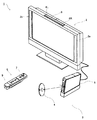
図1を参照して、本発明の一実施形態に係るゲームプログラムを実行するゲーム装置について説明する。以下、説明を具体的にするために、当該装置の一例の据置型のゲーム装置本体5を含むゲームシステムについて説明する。なお、図1は据置型のゲーム装置3を含むゲームシステム1の外観図であり、図2はゲーム装置本体5のブロック図である。以下、当該ゲームシステム1について説明する。
A game device that executes a game program according to an embodiment of the present invention will be described with reference to FIG. Hereinafter, in order to make the description more specific, a game system including a stationary
図1において、ゲームシステム1は、表示手段の一例の家庭用テレビジョン受像機(以下、モニタと記載する)2と、当該モニタ2に接続コードを介して接続する据置型のゲーム装置3とから構成される。モニタ2は、ゲーム装置3から出力された音声信号を音声出力するためのスピーカ2aを備える。また、ゲーム装置3は、本願発明のゲームプログラムの一例となるプログラムを記録した光ディスク4と、当該光ディスク4のゲームプログラムを実行してゲーム画面をモニタ2に表示出力させるためのコンピュータを搭載したゲーム装置本体5と、ゲーム画面に表示されたキャラクタ等を操作するゲームに必要な操作情報をゲーム装置本体5に与えるための入力装置の一例であるユニット付コントローラ6とを備えている。
In FIG. 1, a
また、ゲーム装置本体5は、無線コントローラモジュール19(図2参照)を内蔵する。無線コントローラモジュール19は、ユニット付コントローラ6から無線送信されるデータを受信し、ゲーム装置本体5からユニット付コントローラ6へデータを送信して、ユニット付コントローラ6とゲーム装置本体5とを無線通信によって接続する。さらに、ゲーム装置本体5には、当該ゲーム装置本体5に対して交換可能に用いられる情報記憶媒体の一例の光ディスク4が脱着される。
In addition, the
また、ゲーム装置本体5には、セーブデータ等のデータを固定的に記憶するバックアップメモリとして機能するフラッシュメモリ17(図2参照)が搭載される。ゲーム装置本体5は、光ディスク4に記憶されたゲームプログラム等を実行することによって、その結果をゲーム画像としてモニタ2に表示する。また、ゲームプログラム等は、光ディスク4に限らず、フラッシュメモリ17に予め記録されたものを実行するようにしてもよい。さらに、ゲーム装置本体5は、フラッシュメモリ17に記憶されたセーブデータを用いて、過去に実行されたゲーム状態を再現して、ゲーム画像をモニタ2に表示することもできる。そして、ゲーム装置3のプレイヤは、モニタ2に表示されたゲーム画像を見ながら、ユニット付コントローラ6を操作することによって、ゲーム進行を楽しむことができる。
Further, the
ユニット付コントローラ6は、自機に対して行われた操作の内容を示す操作データをゲーム装置本体5に与えるものである。本実施形態では、ユニット付コントローラ6は、コントローラ7と角速度検出ユニット9とを含む。詳細は後述するが、ユニット付コントローラ6は、コントローラ7に対して角速度検出ユニット9が着脱可能に接続されている構成である。
The unit-equipped controller 6 gives operation data indicating the contents of the operation performed on the own device to the
コントローラ7は、無線コントローラモジュール19を内蔵するゲーム装置本体5へ、例えばBluetooth(ブルートゥース;登録商標)の技術を用いて操作情報等の送信データを無線送信する。コントローラ7は、片手で把持可能な程度の大きさのハウジングと、当該ハウジングの表面に露出して設けられた複数個の操作ボタン(十字キーやスティック等を含む)とが設けられている。また、後述により明らかとなるが、コントローラ7は、当該コントローラ7から見た画像を撮像する撮像情報演算部74を備えている。そして、撮像情報演算部74の撮像対象の一例として、モニタ2の表示画面近傍に2つのLEDモジュール(以下、マーカと記載する)8Lおよび8Rが設置される。これらマーカ8Lおよび8Rは、それぞれモニタ2の前方に向かって例えば赤外光を出力する。また、コントローラ7は、ゲーム装置本体5の無線コントローラモジュール19から無線送信された送信データを通信部75で受信して、当該送信データに応じた音や振動を発生させることもできる。
The
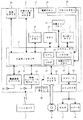
次に、図2を参照して、ゲーム装置本体5の内部構成について説明する。図2は、ゲーム装置本体5の構成を示すブロック図である。ゲーム装置本体5は、CPU(Central Processing Unit)10、システムLSI(Large Scale Integration)11、外部メインメモリ12、ROM/RTC(Read Only Memory/Real Time Clock)13、ディスクドライブ14、およびAV−IC(Audio Video−Integrated Circuit)15等を有する。
Next, the internal configuration of the
CPU10は、光ディスク4に記憶されたゲームプログラムを実行することによってゲーム処理を実行するものであり、ゲームプロセッサとして機能する。CPU10は、システムLSI11に接続される。システムLSI11には、CPU10の他、外部メインメモリ12、ROM/RTC13、ディスクドライブ14、およびAV−IC15が接続される。システムLSI11は、それに接続される各構成要素間のデータ転送の制御、表示すべき画像の生成、外部装置からのデータの取得等の処理を行う。なお、システムLSI11の内部構成については、後述する。揮発性の外部メインメモリ12は、光ディスク4から読み出されたゲームプログラムや、フラッシュメモリ17から読み出されたゲームプログラム等のプログラムを記憶したり、各種データを記憶したりするものであり、CPU10のワーク領域やバッファ領域として用いられる。ROM/RTC13は、ゲーム装置本体5の起動用のプログラムが組み込まれるROM(いわゆるブートROM)と、時間をカウントするクロック回路(RTC)とを有する。ディスクドライブ14は、光ディスク4からプログラムデータやテクスチャデータ等を読み出し、後述する内部メインメモリ35または外部メインメモリ12に読み出したデータを書き込む。
The
また、システムLSI11には、入出力プロセッサ31、GPU(Graphics Processor Unit)32、DSP(Digital Signal Processor)33、VRAM(Video RAM)34、および内部メインメモリ35が設けられる。図示は省略するが、これらの構成要素31〜35は、内部バスによって互いに接続される。
Further, the system LSI 11 is provided with an input /
GPU32は、描画手段の一部を形成し、CPU10からのグラフィクスコマンド(作画命令)に従って画像を生成する。VRAM34は、GPU32がグラフィクスコマンドを実行するために必要なデータ(ポリゴンデータやテクスチャデータ等のデータ)を記憶する。画像が生成される際には、GPU32は、VRAM34に記憶されたデータを用いて画像データを作成する。
The
DSP33は、オーディオプロセッサとして機能し、内部メインメモリ35や外部メインメモリ12に記憶されるサウンドデータや音波形(音色)データを用いて、音声データを生成する。
The DSP 33 functions as an audio processor, and generates sound data using sound data and sound waveform (tone color) data stored in the internal
上述のように生成された画像データおよび音声データは、AV−IC15によって読み出される。AV−IC15は、AVコネクタ16を介して、読み出した画像データをモニタ2に出力するとともに、読み出した音声データをモニタ2に内蔵されるスピーカ2aに出力する。これによって、画像がモニタ2に表示されるとともに音がスピーカ2aから出力される。
The image data and audio data generated as described above are read out by the AV-
入出力プロセッサ(I/Oプロセッサ)31は、それに接続される構成要素との間でデータの送受信を実行したり、外部装置からのデータのダウンロードを実行したりする。入出力プロセッサ31は、フラッシュメモリ17、無線通信モジュール18、無線コントローラモジュール19、拡張コネクタ20、および外部メモリカード用コネクタ21に接続される。無線通信モジュール18にはアンテナ22が接続され、無線コントローラモジュール19にはアンテナ23が接続される。
The input / output processor (I / O processor) 31 transmits / receives data to / from components connected thereto and downloads data from an external device. The input /
入出力プロセッサ31は、無線通信モジュール18およびアンテナ22を介してネットワークに接続し、ネットワークに接続される他のゲーム装置や各種サーバと通信することができる。入出力プロセッサ31は、定期的にフラッシュメモリ17にアクセスし、ネットワークへ送信する必要があるデータの有無を検出し、当該データが有る場合には、無線通信モジュール18およびアンテナ22を介して当該データをネットワークに送信する。また、入出力プロセッサ31は、他のゲーム装置から送信されてくるデータやダウンロードサーバからダウンロードしたデータを、ネットワーク、アンテナ22、および無線通信モジュール18を介して受信し、受信したデータをフラッシュメモリ17に記憶する。CPU10は、ゲームプログラムを実行することにより、フラッシュメモリ17に記憶されたデータを読み出してゲームプログラムで利用する。フラッシュメモリ17には、ゲーム装置本体5と他のゲーム装置や各種サーバとの間で送受信されるデータの他、ゲーム装置本体5を利用してプレイしたゲームのセーブデータ(ゲームの結果データまたは途中データ)が記憶されてもよい。
The input /
また、入出力プロセッサ31は、アンテナ23および無線コントローラモジュール19を介して、コントローラ7(ユニット付コントローラ6)から送信される操作データ等を受信し、内部メインメモリ35または外部メインメモリ12のバッファ領域に記憶(一時記憶)する。なお、内部メインメモリ35には、外部メインメモリ12と同様に、光ディスク4から読み出されたゲームプログラムや、フラッシュメモリ17から読み出されたゲームプログラム等のプログラムを記憶したり、各種データを記憶したりしてもよく、CPU10のワーク領域やバッファ領域として用いられてもかまわない。
Further, the input /
さらに、入出力プロセッサ31には、拡張コネクタ20および外部メモリカード用コネクタ21が接続される。拡張コネクタ20は、USBやSCSIのようなインターフェースのためのコネクタであり、外部記憶媒体のようなメディアを接続したり、他のコントローラのような周辺機器を接続したり、有線の通信用コネクタを接続することによって無線通信モジュール18に替えてネットワークとの通信を行ったりすることができる。外部メモリカード用コネクタ21は、メモリカードのような外部記憶媒体を接続するためのコネクタである。例えば、入出力プロセッサ31は、拡張コネクタ20や外部メモリカード用コネクタ21を介して、外部記憶媒体にアクセスし、データを保存したり、データを読み出したりすることができる。
Furthermore, the
また、ゲーム装置本体5(例えば、前部主面)には、当該ゲーム装置本体5の電源ボタン24、ゲーム処理のリセットボタン25、光ディスク4を脱着する投入口、およびゲーム装置本体5の投入口から光ディスク4を取り出すイジェクトボタン26等が設けられている。電源ボタン24およびリセットボタン25は、システムLSI11に接続される。電源ボタン24がオンされると、ゲーム装置本体5の各構成要素に対して、図示しないACアダプタを介して電力が供給される。リセットボタン25が押されると、システムLSI11は、ゲーム装置本体5の起動プログラムを再起動する。イジェクトボタン26は、ディスクドライブ14に接続される。イジェクトボタン26が押されると、ディスクドライブ14から光ディスク4が排出される。
In addition, on the game apparatus main body 5 (for example, the front main surface), the power button 24 of the game apparatus
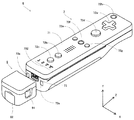
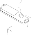
図3および図4を参照して、ユニット付コントローラ6について説明する。なお、図3は、ユニット付コントローラ6の上側後方から見た一例を示す斜視図である。図4は、コントローラ7を下側前方から見た一例を示す斜視図である。
The unit-equipped controller 6 will be described with reference to FIGS. 3 and 4. FIG. 3 is a perspective view showing an example of the unit-equipped controller 6 as seen from the upper rear side. FIG. 4 is a perspective view showing an example of the
図3および図4において、コントローラ7は、例えばプラスチック成型によって形成されたハウジング71を有しており、当該ハウジング71に複数の操作部72が設けられている。ハウジング71は、その前後方向を長手方向とした略直方体形状を有しており、全体として大人や子供の片手で把持可能な大きさである。
3 and 4, the
ハウジング71上面の中央前面側に、十字キー72aが設けられる。この十字キー72aは、十字型の4方向プッシュスイッチであり、4つの方向(前後左右)に対応する操作部分が十字の突出片にそれぞれ90°間隔で配置される。プレイヤが十字キー72aのいずれかの操作部分を押下することによって前後左右いずれかの方向を選択される。例えばプレイヤが十字キー72aを操作することによって、仮想ゲーム世界に登場するプレイヤキャラクタ等の移動方向を指示したり、複数の選択肢から選択指示したりすることができる。
A cross key 72 a is provided on the center front side of the upper surface of the
なお、十字キー72aは、上述したプレイヤの方向入力操作に応じて操作信号を出力する操作部であるが、他の態様の操作部でもかまわない。例えば、十字方向に4つのプッシュスイッチを配設し、プレイヤによって押下されたプッシュスイッチに応じて操作信号を出力する操作部を設けてもかまわない。さらに、上記4つのプッシュスイッチとは別に、上記十字方向が交わる位置にセンタスイッチを配設し、4つのプッシュスイッチとセンタスイッチとを複合した操作部を設けてもかまわない。また、ハウジング71上面から突出した傾倒可能なスティック(いわゆる、ジョイスティック)を倒すことによって、傾倒方向に応じて操作信号を出力する操作部を十字キー72aの代わりに設けてもかまわない。さらに、水平移動可能な円盤状部材をスライドさせることによって、当該スライド方向に応じた操作信号を出力する操作部を、上記十字キー72aの代わりに設けてもかまわない。また、タッチパッドを、十字キー72aの代わりに設けてもかまわない。
Note that the cross key 72a is an operation unit that outputs an operation signal in response to the above-described direction input operation of the player, but may be an operation unit of another mode. For example, four push switches may be provided in the cross direction, and an operation unit that outputs an operation signal according to the push switch pressed by the player may be provided. Further, apart from the four push switches, a center switch may be provided at a position where the cross direction intersects, and an operation unit in which the four push switches and the center switch are combined may be provided. An operation unit that outputs an operation signal in accordance with the tilt direction by tilting a tiltable stick (so-called joystick) protruding from the upper surface of the
ハウジング71上面の十字キー72aより後面側に、複数の操作ボタン72b〜72gが設けられる。操作ボタン72b〜72gは、プレイヤがボタン頭部を押下することによって、それぞれの操作ボタン72b〜72gに割り当てられた操作信号を出力する操作部である。例えば、操作ボタン72b〜72dには、1番ボタン、2番ボタン、およびAボタン等としての機能が割り当てられる。また、操作ボタン72e〜72gには、マイナスボタン、ホームボタン、およびプラスボタン等としての機能が割り当てられる。これら操作ボタン72a〜72gは、ゲーム装置本体5が実行するゲームプログラムに応じてそれぞれの操作機能が割り当てられる。なお、図3に示した配置例では、操作ボタン72b〜72dは、ハウジング71上面の中央前後方向に沿って並設されている。また、操作ボタン72e〜72gは、ハウジング71上面の左右方向に沿って操作ボタン72bおよび72dの間に並設されている。そして、操作ボタン72fは、その上面がハウジング71の上面に埋没しており、プレイヤが不意に誤って押下することのないタイプのボタンである。
A plurality of
また、ハウジング71上面の十字キー72aより前面側に、操作ボタン72hが設けられる。操作ボタン72hは、遠隔からゲーム装置本体5の電源をオン/オフする電源スイッチである。この操作ボタン72hも、その上面がハウジング71の上面に埋没しており、プレイヤが不意に誤って押下することのないタイプのボタンである。
An
また、ハウジング71上面の操作ボタン72cより後面側に、複数のLED702が設けられる。ここで、コントローラ7は、他のコントローラ7と区別するためにコントローラ種別(番号)が設けられている。例えば、LED702は、コントローラ7に現在設定されている上記コントローラ種別をプレイヤに通知するために用いられる。具体的には、無線コントローラモジュール19からコントローラ7へ、複数のLED702のうち、上記コントローラ種別に対応するLEDを点灯させるための信号が送信される。
A plurality of
また、ハウジング71上面には、操作ボタン72bおよび操作ボタン72e〜72gの間に後述するスピーカ(図5に示すスピーカ706)からの音を外部に放出するための音抜き孔が形成されている。
Further, on the upper surface of the
一方、ハウジング71下面には、凹部が形成されている。ハウジング71下面の凹部は、プレイヤがコントローラ7の前面をマーカ8Lおよび8Rに向けて片手で把持したときに、当該プレイヤの人差し指や中指が位置するような位置に形成される。そして、上記凹部の傾斜面には、操作ボタン72iが設けられる。操作ボタン72iは、例えばBボタンとして機能する操作部である。
On the other hand, a recess is formed on the lower surface of the
また、ハウジング71前面には、撮像情報演算部74の一部を構成する撮像素子743が設けられる。ここで、撮像情報演算部74は、コントローラ7が撮像した画像データを解析してその中で輝度が高い場所を判別してその場所の重心位置やサイズなどを検出するためのシステムであり、例えば、最大200フレーム/秒程度のサンプリング周期であるため比較的高速なコントローラ7の動きでも追跡して解析することができる。この撮像情報演算部74の詳細な構成については、後述する。また、ハウジング71の後面には、コネクタ73が設けられている。コネクタ73は、例えばエッジコネクタであり、例えば接続ケーブルと嵌合して接続するために利用される。図1および図3に示したユニット付コントローラ6の一例では、コネクタ73を介して、コントローラ7の後面に角速度検出ユニット9が着脱自在に装着される。
An
ここで、以下の説明を具体的にするために、ユニット付コントローラ6(コントローラ7)に対して設定する座標系について定義する。図3および図4に示すように、互いに直交するXYZ軸をユニット付コントローラ6(コントローラ7)に対して定義する。具体的には、コントローラ7の前後方向となるハウジング71の長手方向をZ軸とし、コントローラ7の前面(撮像情報演算部74が設けられている面)方向をZ軸正方向とする。また、コントローラ7の上下方向をY軸とし、ハウジング71の上面(操作ボタン72aが設けられた面)方向をY軸正方向とする。さらに、コントローラ7の左右方向をX軸とし、ハウジング71の右側面(図3で表されている側面)方向をX軸正方向とする。
Here, in order to make the following description concrete, a coordinate system set for the controller with unit 6 (controller 7) is defined. As shown in FIGS. 3 and 4, XYZ axes orthogonal to each other are defined for the controller 6 with a unit (controller 7). Specifically, the longitudinal direction of the
角速度検出ユニット9は、3軸周りの角速度を検知するジャイロセンサ(図7に示す2軸ジャイロセンサ95および1軸ジャイロセンサ96)を有する。角速度検出ユニット9の前端(図3に示すZ軸正方向側の端部)には、コネクタ73に接続可能なプラグ(図7に示すプラグ93)が設けられる。さらに、プラグ93の両側にはフック(図示せず)が設けられる。角速度検出ユニット9がコントローラ7に対して装着される状態では、プラグ93がコネクタ73に接続されるとともに、上記フックがコントローラ7の係止穴73aに係止する。これによって、コントローラ7と角速度検出ユニット9とがしっかりと固定される。また、角速度検出ユニット9は、側面(図3に示すX軸方向の面)にボタン91を有している。ボタン91は、それを押下すれば上記フックの係止穴73aに対する係止状態を解除することができるように構成されている。したがって、ボタン91を押下しながらプラグ93をコネクタ73から抜くことによって、角速度検出ユニット9をコントローラ7から離脱することができる。そして、プレイヤは、角速度検出ユニット9をコントローラ7に装着した状態や角速度検出ユニット9をコントローラ7から取り外したコントローラ7単体の状態で操作することが可能となる。
The angular velocity detection unit 9 includes gyro sensors (two-
また、角速度検出ユニット9の後端には、上記コネクタ73と同形状のコネクタが設けられる。したがって、コントローラ7(のコネクタ73)に対して装着可能な他の機器は、角速度検出ユニット9の後端コネクタに対しても装着可能である。なお、図3においては、当該後端コネクタに対してカバー92が着脱可能に装着されている。
A connector having the same shape as the
次に、図5および図6を参照して、コントローラ7の内部構造について説明する。なお、図5は、コントローラ7の上筐体(ハウジング71の一部)を外した状態を後面側から見た斜視図である。図6は、コントローラ7の下筐体(ハウジング71の一部)を外した状態を前面側から見た斜視図である。ここで、図6に示す基板700は、図5に示す基板700の裏面から見た斜視図となっている。
Next, the internal structure of the
図5において、ハウジング71の内部には基板700が固設されており、当該基板700の上主面上に操作ボタン72a〜72h、加速度センサ701、LED702、およびアンテナ754等が設けられる。そして、これらは、基板700等に形成された配線(図示せず)によってマイコン751等(図6、図7参照)に接続される。また、無線モジュール753(図7参照)およびアンテナ754によって、コントローラ7がワイヤレスコントローラとして機能する。なお、ハウジング71内部には図示しない水晶振動子が設けられており、後述するマイコン751の基本クロックを生成する。また、基板700の上主面上に、スピーカ706およびアンプ708が設けられる。また、加速度センサ701は、操作ボタン72dの左側の基板700上(つまり、基板700の中央部ではなく周辺部)に設けられる。したがって、加速度センサ701は、コントローラ7の長手方向を軸とした回転に応じて、重力加速度の方向変化に加え、遠心力による成分が含まれる加速度を検出することができるので、所定の演算により、検出される加速度データからコントローラ7の動きを良好な感度でゲーム装置本体5等が判定することができる。
In FIG. 5, a
一方、図6において、基板700の下主面上の前端縁に撮像情報演算部74が設けられる。撮像情報演算部74は、コントローラ7の前方から順に赤外線フィルタ741、レンズ742、撮像素子743、および画像処理回路744によって構成されており、それぞれ基板700の下主面に取り付けられる。また、基板700の下主面上の後端縁にコネクタ73が取り付けられる。さらに、基板700の下主面上にサウンドIC707およびマイコン751が設けられている。サウンドIC707は、基板700等に形成された配線によってマイコン751およびアンプ708と接続され、ゲーム装置本体5から送信されたサウンドデータに応じてアンプ708を介してスピーカ706に音声信号を出力する。
On the other hand, in FIG. 6, an imaging
そして、基板700の下主面上には、バイブレータ704が取り付けられる。バイブレータ704は、例えば振動モータやソレノイドである。バイブレータ704は、基板700等に形成された配線によってマイコン751と接続され、ゲーム装置本体5から送信された振動データに応じてその作動をオン/オフする。バイブレータ704が作動することによってコントローラ7に振動が発生するので、それを把持しているプレイヤの手にその振動が伝達され、いわゆる振動対応ゲームが実現できる。ここで、バイブレータ704は、ハウジング71のやや前方寄りに配置されるため、プレイヤが把持している状態において、ハウジング71が大きく振動することになり、振動を感じやすくなる。
A
次に、図7を参照して、ユニット付コントローラ6(角速度検出ユニット9を装着したコントローラ7)の内部構成について説明する。なお、図7は、ユニット付コントローラ6の構成の一例を示すブロック図である。
Next, the internal configuration of the unit-equipped controller 6 (the
図7において、コントローラ7は、上述した操作部72、撮像情報演算部74、加速度センサ701、バイブレータ704、スピーカ706、サウンドIC707、およびアンプ708の他に、その内部に通信部75を備えている。
In FIG. 7, the
撮像情報演算部74は、赤外線フィルタ741、レンズ742、撮像素子743、および画像処理回路744を含んでいる。赤外線フィルタ741は、コントローラ7の前方から入射する光から赤外線のみを通過させる。レンズ742は、赤外線フィルタ741を透過した赤外線を集光して撮像素子743へ出射する。撮像素子743は、例えばCMOSセンサやあるいはCCDのような固体撮像素子であり、レンズ742が集光した赤外線を撮像する。したがって、撮像素子743は、赤外線フィルタ741を通過した赤外線だけを撮像して画像データを生成する。撮像素子743で生成された画像データは、画像処理回路744で処理される。具体的には、画像処理回路744は、撮像素子743から得られた画像データを処理して高輝度部分を検知し、それらの位置座標や面積を検出した結果を示す処理結果データを通信部75へ出力する。なお、これらの撮像情報演算部74は、コントローラ7のハウジング71に固設されており、ハウジング71自体の方向を変えることによってその撮像方向を変更することができる。
The imaging
コントローラ7は、3軸(X、Y、Z軸)の加速度センサ701を備えていることが好ましい。この3軸の加速度センサ701は、3方向、すなわち、上下方向(図3に示すY軸)、左右方向(図3に示すX軸)、および前後方向(図3に示すZ軸)で直線加速度を検知する。また、少なくとも1軸方向に沿った直線加速度をそれぞれ検知する加速度検出手段を使用してもよい。例えば、これらの加速度センサ701は、アナログ・デバイセズ株式会社(Analog Devices, Inc.)またはSTマイクロエレクトロニクス社(STMicroelectronics N.V.)から入手可能であるタイプのものでもよい。加速度センサ701は、シリコン微細加工されたMEMS(Micro Electro Mechanical Systems:微小電子機械システム)の技術に基づいた静電容量式(静電容量結合式)であることが好ましい。しかしながら、既存の加速度検出手段の技術(例えば、圧電方式や圧電抵抗方式)あるいは将来開発される他の適切な技術を用いて、加速度センサ701が提供されてもよい。
The
加速度センサ701に用いられるような加速度検出手段は、加速度センサ701の持つ各軸に対応する直線に沿った加速度(直線加速度)のみを検知することができる。つまり、加速度センサ701からの直接の出力は、それら3軸のそれぞれに沿った直線加速度(静的または動的)を示す信号である。このため、加速度センサ701は、非直線状(例えば、円弧状)の経路に沿った動き、回転、回転運動、角変位、傾斜、位置、または姿勢等の物理特性を直接検知することはできない。
The acceleration detecting means used in the
しかしながら、加速度センサ701から出力される加速度の信号に基づいて、ゲーム装置のプロセッサ(例えばCPU10)またはコントローラのプロセッサ(例えばマイコン751)等のコンピュータが処理を行うことによって、コントローラ7に関するさらなる情報を推測または算出(判定)することができることは、当業者であれば本明細書の説明から容易に理解できるであろう。
However, based on the acceleration signal output from the
例えば、加速度センサ701を搭載するコントローラ7が静的な状態であることを前提としてコンピュータ側で処理する場合(すなわち、加速度センサ701によって検出される加速度が重力加速度のみであるとして処理する場合)、コントローラ7が現実に静的な状態であれば、検出された加速度に基づいてコントローラ7の姿勢が重力方向に対して傾いているか否か、またはどの程度傾いているかを知ることができる。具体的には、加速度センサ701の検出軸が鉛直下方向を向いている状態を基準としたとき、当該検出軸方向に1G(重力加速度)が作用しているか否かだけでコントローラ7が鉛直下方向に対して傾いているか否かを知ることができる。また、上記検出軸方向に作用している加速度の大きさによって、コントローラ7が鉛直下方向に対してどの程度傾いているかも知ることができる。また、多軸方向の加速度を検出可能な加速度センサ701の場合には、さらに各軸に対して検出された加速度の信号に対して処理を施すことによって、重力方向に対してコントローラ7がどの程度傾いているかをより詳細に知ることができる。この場合において、加速度センサ701からの出力に基づいて、プロセッサがコントローラ7の傾き角度のデータを算出する処理を行ってもよいが、当該傾き角度のデータを算出する処理を行うことなく、加速度センサ701からの出力に基づいて、おおよそのコントローラ7の傾き具合を推定するような処理としてもよい。このように、加速度センサ701をプロセッサと組み合わせて用いることによって、コントローラ7の傾き、姿勢、または位置を判定することができる。
For example, when processing is performed on the computer side on the assumption that the
一方、加速度センサ701が動的な状態であることを前提とする場合には、当該加速度センサ701が重力加速度成分に加えて加速度センサ701の動きに応じた加速度を検出するので、重力加速度成分を所定の処理により除去すれば、コントローラ7の動き方向等を知ることができる。具体的には、加速度センサ701を備えるコントローラ7がプレイヤの手で動的に加速されて動かされる場合に、加速度センサ701によって生成される加速度信号を処理することによって、コントローラ7の様々な動きおよび/または位置を算出することができる。なお、加速度センサ701が動的な状態であることを前提とする場合であっても、加速度センサ701の動きに応じた加速度を所定の処理により除去すれば、重力方向に対するコントローラ7の傾きを知ることが可能である。
On the other hand, when it is assumed that the
他の実施例では、加速度センサ701は、信号をマイコン751に出力する前に内蔵の加速度検出手段から出力される加速度信号に対して所望の処理を行うための、組込み式の信号処理装置または他の種類の専用の処理装置を備えていてもよい。例えば、組込み式または専用の処理装置は、加速度センサ701が静的な加速度(例えば、重力加速度)を検出するためのものである場合、検知された加速度信号をそれに相当する傾斜角(あるいは、他の好ましいパラメータ)に変換するものであってもよい。加速度センサ701でそれぞれ検知された加速度を示すデータは、通信部75に出力される。
In another embodiment, the
通信部75は、マイクロコンピュータ(Micro Computer:マイコン)751、メモリ752、無線モジュール753、およびアンテナ754を含んでいる。マイコン751は、処理の際にメモリ752を記憶領域として用いながら、送信データを無線送信する無線モジュール753を制御する。また、マイコン751は、アンテナ754を介して無線モジュール753が受信したゲーム装置本体5からのデータに応じて、サウンドIC707およびバイブレータ704の動作を制御する。サウンドIC707は、通信部75を介してゲーム装置本体5から送信されたサウンドデータ等を処理する。また、マイコン751は、通信部75を介してゲーム装置本体5から送信された振動データ(例えば、バイブレータ704をONまたはOFFする信号)等に応じて、バイブレータ704を作動させる。また、マイコン751は、コネクタ73に接続されている。角速度検出ユニット9から送信されてくるデータは、コネクタ73を介してマイコン751に入力される。以下、角速度検出ユニット9の構成について説明する。
The
角速度検出ユニット9は、プラグ93、マイコン94、2軸ジャイロセンサ95、および1軸ジャイロセンサ96を備えている。上述のように、角速度検出ユニット9は、3軸(本実施形態では、XYZ軸)周りの角速度を検出し、検出した角速度を示すデータ(角速度データ)をコントローラ7へ出力する。
The angular velocity detection unit 9 includes a
2軸ジャイロセンサ95は、X軸周りの角速度およびY軸周りの(単位時間あたりの)角速度を検出する。また、1軸ジャイロセンサ96は、Z軸周りの(単位時間あたりの)角速度を検出する。
The
なお、本実施形態では、3軸周りの角速度を検出するために、2軸ジャイロセンサ95と1軸ジャイロセンサ96とを用いる構成としたが、他の実施形態においては、3軸周りの角速度を検出することができればよく、用いるジャイロセンサの数および組み合わせはどのようなものであってもよい。なお、2軸ジャイロセンサ95および1軸ジャイロセンサ96を総称して説明する場合は、ジャイロセンサ95および96と記載する。
In this embodiment, the two-
各ジャイロセンサ95および96で検出された角速度を示すデータは、マイコン94に出力される。したがって、マイコン94には、XYZ軸の3軸周りの角速度を示すデータが入力されることになる。マイコン94は、上記3軸周りの角速度を示すデータを角速度データとしてプラグ93を介してコントローラ7へ出力する。なお、マイコン94からコントローラ7への出力は、所定の周期毎に逐次行われるが、ゲームの処理は1/60秒を単位として(1フレーム時間として)行われることが一般的であるので、この時間以下の周期で出力を行うことが好ましい。
Data indicating the angular velocity detected by each
コントローラ7の説明に戻り、コントローラ7に設けられた操作部72からの操作信号(キーデータ)、加速度センサ701からの3軸方向の加速度信号(X、Y、およびZ軸方向加速度データ)、撮像情報演算部74からの処理結果データ、および角速度検出ユニット9からの3軸周りの角速度を示すデータ(X、Y、Z軸周り角速度データ)は、マイコン751に出力される。マイコン751は、入力した各データ(キーデータ、X、Y、およびZ軸方向加速度データ、処理結果データ、X、Y、およびZ軸周り角速度データ)を無線コントローラモジュール19へ送信する送信データとして一時的にメモリ752に格納する。ここで、通信部75から無線コントローラモジュール19への無線送信は、所定の周期毎に行われるが、ゲームの処理は1/60秒を単位として行われることが一般的であるので、それよりも短い周期で送信を行うことが必要となる。具体的には、ゲームの処理単位は16.7ms(1/60秒)であり、ブルートゥース(登録商標)で構成される通信部75の送信間隔は5msである。マイコン751は、無線コントローラモジュール19への送信タイミングが到来すると、メモリ752に格納されている送信データを一連の操作情報として出力し、無線モジュール753へ出力する。そして、無線モジュール753は、例えばブルートゥース(登録商標)の技術を用いて、操作情報を示す電波信号を所定周波数の搬送波を用いてアンテナ754から放射する。つまり、コントローラ7に設けられた操作部72からのキーデータ、加速度センサ701からのX、Y、およびZ軸方向加速度データ、撮像情報演算部74からの処理結果データ、角速度検出ユニット9からのX、Y、およびZ軸周り角速度データがコントローラ7から送信される。そして、ゲーム装置本体5の無線コントローラモジュール19でその電波信号を受信し、ゲーム装置本体5で当該電波信号を復調や復号することによって、一連の操作情報(キーデータ、X、Y、およびZ軸方向加速度データ、処理結果データ、X、Y、およびZ軸周り角速度データ)を取得する。そして、ゲーム装置本体5のCPU10は、取得した操作情報とゲームプログラムとに基づいて、ゲーム処理を行う。なお、ブルートゥース(登録商標)の技術を用いて通信部75を構成する場合、通信部75は、他のデバイスから無線送信された送信データを受信する機能も備えることができる。
Returning to the description of the
ユニット付コントローラ6を用いることによって、プレイヤは、各操作ボタンを押下する従来の一般的なゲーム操作に加えて、ユニット付コントローラ6を任意の傾斜角度に傾ける操作を行うことができる。その他、ユニット付コントローラ6によれば、プレイヤは、ユニット付コントローラ6によって画面上の任意の位置を指示する操作、および、ユニット付コントローラ6自体を動かす操作等を行うこともできる。 By using the unit-equipped controller 6, the player can perform an operation of tilting the unit-equipped controller 6 to an arbitrary inclination angle in addition to the conventional general game operation of pressing each operation button. In addition, according to the unit-equipped controller 6, the player can also perform an operation of instructing an arbitrary position on the screen by the unit-equipped controller 6 and an operation of moving the unit-equipped controller 6 itself.
なお、上記一連の操作情報に角速度検出ユニット9がコントローラ7に装着されているか否かを示すデータも含ませて、コントローラ7からゲーム装置本体5へ送信データを送信してもかまわない。この送信データを解析することによって、ゲーム装置本体5は、角速度検出ユニット9がコントローラ7に装着されているか否かを即時に判別することができる。なお、角速度検出ユニット9がコントローラ7に装着されていない場合、すなわちプレイヤがコントローラ7単体で操作している場合、角速度検出ユニット9からの3軸周りの角速度を示すデータ(X、Y、Z軸周り角速度データ)は、マイコン751に出力されることがない。この場合、マイコン751は、入力している各データ(キーデータ、X、Y、およびZ軸方向加速度データ、処理結果データ)を無線コントローラモジュール19へ送信する送信データとして一時的にメモリ752に格納し、ゲーム装置本体5へ送信する。つまり、ゲーム装置本体5は、コントローラ7からの送信データにX、Y、Z軸周り角速度データが含まれているか否かによって、角速度検出ユニット9がコントローラ7に装着されているか否かを判別することもできる。なお、以下の説明において、コントローラ7に角速度検出ユニット9が装着されていない入力装置を「コントローラ7単体」と記載して、コントローラ7に角速度検出ユニット9が装着されている入力装置を「ユニット付コントローラ6」と記載することによって、両者を区別することがある。そして、コントローラ7単体やユニット付コントローラ6が、本発明の入力装置の一例に相当する。
Note that the series of operation information may include data indicating whether or not the angular velocity detection unit 9 is attached to the
次に、ゲーム装置本体5が行う具体的な処理を説明する前に、図8〜図10を用いて本ゲーム装置本体5で行うゲームの概要について説明する。なお、図8は、モニタ2に表示されるゲーム画像の一例を示す図である。図9は、コントローラ7単体で振り動かされた際に、当該振り動作に応じてプレイヤオブジェクトOBJが移動する一例を示す図である。図10Aおよび図10Bは、コントローラ7単体での振り動作に応じて設定された移動方向が補正される一例を示す図である。
Next, before describing specific processing performed by the
図8において、モニタ2にはプレイヤオブジェクトOBJが仮想ゲーム世界を移動する様子が表示される。図8に示した一例では、プレイヤオブジェクトOBJが2次元の仮想ゲーム世界を左方向に進む(ゲーム進行方向)ゲームを示している。例えば、モニタ2に表示される仮想ゲーム世界は、所定のスピードで右スクロールし、プレイヤオブジェクトOBJがモニタ2に表示される仮想ゲーム世界内を移動する。つまり、仮想ゲーム世界内で仮想カメラが左方向に移動し、画面に表示される仮想ゲーム世界は右方向へ移動するので、ゲームは左に向かって進行することになる。そして、プレイヤは、プレイヤオブジェクトOBJを、仮想ゲーム世界に登場するターゲットTGと衝突させることによって所定の点数を得ることができる。
In FIG. 8, the
プレイヤオブジェクトOBJは、入力装置の振り方向に応じて仮想ゲーム世界内を移動する。ここで、上記ゲームは、ユニット付コントローラ6の振り方向に応じてゲーム進行することも可能であるし、コントローラ7単体の振り方向に応じてゲーム進行することも可能である。以下、コントローラ7単体の振り方向に応じてゲームが進行する例を用いて説明する。
The player object OBJ moves in the virtual game world according to the swing direction of the input device. Here, the game can proceed in accordance with the swing direction of the unit-equipped controller 6, or the game can proceed in accordance with the swing direction of the
図9において、実空間における右から左へコントローラ7単体が振られることに応じて、モニタ2に向かって仮想ゲーム世界の右から左へプレイヤオブジェクトOBJが移動する様子を示している。例えば、プレイヤがコントローラ7単体を振ることによって生じる加速度が加速度センサ701で検出され、当該加速度を示すデータがゲーム装置本体5へ送信される。そして、ゲーム装置本体5では、受信した加速度データに基づいて、コントローラ7単体が振られた方向を算出し、算出された振り方向に応じてプレイヤオブジェクトOBJの移動方向を設定する。この移動方向の設定において、ゲーム装置本体5では、コントローラ7単体の振り方向に応じてゲームを進行する場合、プレイヤオブジェクトOBJがターゲットTGに当たりやすいように移動方向を補正する。以下、プレイヤオブジェクトOBJの移動方向を補正する対象となるターゲットTGを、補正ターゲットTGと称することがある。
FIG. 9 shows a state in which the player object OBJ moves from the right to the left in the virtual game world toward the
図10Aおよび図10Bにおいて、補正ターゲットTGには、誘導元範囲と誘導先範囲とが設定されている。誘導元範囲は、コントローラ7単体の振り方向に応じて仮想ゲーム世界に設定されたプレイヤオブジェクトOBJの移動方向を、補正対象とするか否かを判断する。設定された移動方向が現時点のプレイヤオブジェクトOBJの位置から誘導元範囲内を示す場合、当該誘導元範囲を設定している補正ターゲットTGに当該移動方向を近づけるように補正する。例えば、誘導元範囲は、プレイヤオブジェクトOBJと補正ターゲットTGとを結ぶ方向に対して垂直な方向(直線L)に沿って、補正ターゲットTGを中心とした範囲長さRoに設定される。
10A and 10B, a guidance source range and a guidance destination range are set for the correction target TG. The guidance source range determines whether or not the moving direction of the player object OBJ set in the virtual game world is to be corrected according to the swing direction of the
誘導先範囲は、プレイヤオブジェクトOBJの移動方向を補正ターゲットTGに近づける割合を設定する。例えば、補正対象となった移動方向は、誘導先範囲/誘導元範囲の割合で補正ターゲットTGに近づくように補正される。 The guidance destination range sets a rate at which the moving direction of the player object OBJ approaches the correction target TG. For example, the movement direction to be corrected is corrected so as to approach the correction target TG at the ratio of the guide destination range / guide source range.
具体的には、誘導先範囲は、プレイヤオブジェクトOBJと補正ターゲットTGとを結ぶ方向に対して垂直な方向(直線L)に沿って、補正ターゲットTGを中心とした範囲長さRt(Rt<Ro)に設定される。この場合、補正対象となった移動方向は、Rt/Roの割合で補正ターゲットTGに近づくように補正される。具体的には、補正前の移動方向と直線Lとの交点を点P0とし、点P0から補正ターゲットTGの中心までの距離をa(a<Ro/2)とする。この場合、距離aに応じて、直線Lに沿って補正ターゲットTGの中心から距離bとなる点P0側の点P1が設定される。ここで、距離bは、b=a*Rt/Roで算出される。そして、現時点のプレイヤオブジェクトOBJの位置から点P0に向かう補正前の移動方向は、現時点のプレイヤオブジェクトOBJの位置から点P1に向かう方向へ補正される。 Specifically, the guidance destination range is a range length Rt (Rt <Ro) centered on the correction target TG along a direction (straight line L) perpendicular to the direction connecting the player object OBJ and the correction target TG. ). In this case, the movement direction to be corrected is corrected so as to approach the correction target TG at a ratio of Rt / Ro. Specifically, the intersection point between the movement direction before correction and the straight line L is defined as a point P0, and the distance from the point P0 to the center of the correction target TG is defined as a (a <Ro / 2). In this case, a point P1 on the point P0 side that is a distance b from the center of the correction target TG along the straight line L is set according to the distance a. Here, the distance b is calculated by b = a * Rt / Ro. Then, the moving direction before correction from the current position of the player object OBJ toward the point P0 is corrected to a direction from the current position of the player object OBJ toward the point P1.
上述した移動方向の補正例から明らかなように、誘導先範囲のサイズ(範囲長さRt)を補正ターゲットTGのサイズより大きく設定することによって、補正後の移動方向が必ず補正ターゲットTGと交差するとは限らず、結果的にプレイヤオブジェクトOBJが補正ターゲットTGと衝突しないこともあり得る。つまり、移動方向が誘導元範囲内となった場合、当該移動方向が補正ターゲットTGに近づくように補正されるが、プレイヤオブジェクトOBJと補正ターゲットTGとが衝突するか否かについては当該移動方向が補正ターゲットTGにある程度近づいている場合に限られる。そのため、補正が行われても必ず補正ターゲットTGに命中するわけではないので、ゲームが不自然に簡単になり過ぎることを抑えることができる。また、誘導元範囲は、移動方向を補正対象とするか否かを判断するものとなる。したがって、誘導先範囲(範囲長さRt)のサイズおよび/または誘導元範囲のサイズ(範囲長さRo)を変更することによって、様々なゲームの難易度を調整することが可能である。難易度を低くしたい場合には、誘導先範囲の幅を補正ターゲットTGと同じにすれば、移動方向が誘導元範囲に向かっている場合には、補正によって必ずプレイヤオブジェクトOBJが補正ターゲットTGに命中することになる。 As is clear from the above-described correction example of the moving direction, if the size of the guide destination range (range length Rt) is set larger than the size of the correction target TG, the corrected moving direction always intersects the correction target TG. The player object OBJ may not collide with the correction target TG as a result. That is, when the moving direction falls within the guidance source range, the moving direction is corrected so as to approach the correction target TG, but whether or not the player object OBJ and the correction target TG collide is determined by the moving direction. This is limited to the case where the correction target TG is approached to some extent. Therefore, even if correction is performed, the correction target TG is not necessarily hit, so that it is possible to prevent the game from becoming unnaturally easy. In addition, the guidance source range determines whether or not the moving direction is a correction target. Therefore, it is possible to adjust the difficulty level of various games by changing the size of the guidance destination range (range length Rt) and / or the size of the guidance source range (range length Ro). If it is desired to lower the difficulty level, the width of the guidance destination range is made the same as that of the correction target TG. If the movement direction is toward the guidance source range, the player object OBJ always hits the correction target TG by the correction. Will do.
次に、ゲームシステム1において行われるゲーム処理の詳細を説明する。まず、図11を参照して、ゲーム処理において用いられる主なデータについて説明する。なお、図11は、ゲーム装置本体5の外部メインメモリ12および/または内部メインメモリ35(以下、2つのメインメモリを総称して、単にメインメモリと記載する)に記憶される主なデータおよびプログラムを示す図である。
Next, the details of the game process performed in the
図11に示すように、メインメモリのデータ記憶領域には、加速度データDa、角速度データDb、難易度データDc、加速度ベクトルデータDd、重力ベクトルデータDe、差分ベクトルデータDf、移動ベクトルデータDg、補正ターゲットデータDh、プレイヤオブジェクト位置データDi、および画像データDj等が記憶される。なお、メインメモリには、図11に示す情報に含まれるデータの他、ゲームに登場するプレイヤオブジェクトOBJ以外の他のオブジェクト等に関するデータ(位置データ等)や仮想ゲーム世界に関するデータ(背景のデータ等)等、ゲーム処理に必要なデータが記憶される。また、メインメモリのプログラム記憶領域には、ゲームプログラムを構成する各種プログラム群Paが記憶される。 As shown in FIG. 11, in the data storage area of the main memory, acceleration data Da, angular velocity data Db, difficulty data Dc, acceleration vector data Dd, gravity vector data De, difference vector data Df, movement vector data Dg, correction Target data Dh, player object position data Di, image data Dj, and the like are stored. In addition to the data included in the information shown in FIG. 11, the main memory stores data (position data, etc.) related to objects other than the player object OBJ that appears in the game, data related to the virtual game world (background data, etc. And the like, data necessary for game processing is stored. Various program groups Pa constituting the game program are stored in the program storage area of the main memory.
加速度データDaは、コントローラ7に生じた加速度を示すデータであり、コントローラ7から送信データとして送信されてくる一連の操作情報に含まれる加速度データが格納される。この加速度データDaには、加速度センサ701がX軸成分に対して検出した加速度を示すX軸方向加速度データDa1、Y軸成分に対して検出した加速度を示すY軸方向加速度データDa2、およびZ軸成分に対して検出した加速度を示すZ軸方向加速度データDa3が含まれる。
The acceleration data Da is data indicating the acceleration generated in the
角速度データDbは、角速度検出ユニット9のジャイロセンサ95および96によって検出された角速度を示すデータであり、使用されるユニット付コントローラ6毎に対応させて格納される。例えば、角速度データDbは、ユニット付コントローラ6(ジャイロセンサ95および96)に生じた角速度を示すデータであり、ユニット付コントローラ6から送信データとして送信されてくる一連の操作情報に含まれる角速度データが格納される。角速度データDbには、ジャイロセンサ95および96が検出したX軸周りの角速度v1を示すX軸周り角速度データDb1、Y軸周りの角速度v2を示すY軸周り角速度データDb2、Z軸周りの角速度v3を示すZ軸周り角速度データDb3が含まれる。
The angular velocity data Db is data indicating the angular velocity detected by the
なお、ゲーム装置本体5に備える無線コントローラモジュール19は、角速度検出ユニット9が装着されたコントローラ7から所定周期(例えば、1/200秒毎)に送信される操作情報に含まれる加速度データおよび角速度データを受信し、無線コントローラモジュール19に備える図示しないバッファに蓄える。その後、例えば、上記バッファに蓄えられた角速度データおよび角速度データがゲーム処理周期である1フレーム毎(例えば、1/60秒毎)に当該期間中に蓄えられたデータが読み出されて、メインメモリの加速度データDaおよび角速度データDbが更新される。
The wireless controller module 19 provided in the
このとき、操作情報を受信する周期と処理周期とが異なるために、上記バッファには複数の時点に受信した操作情報が記述されていることになる。後述する処理の説明においては、後述する各ステップにおいて、複数の時点に受信した操作情報のうち最新の操作情報のみを常に用いて処理して、次のステップに進める態様を用いる。 At this time, since the cycle for receiving the operation information is different from the processing cycle, the operation information received at a plurality of times is described in the buffer. In the description of the processing to be described later, a mode is used in which, in each step to be described later, only the latest operation information among the operation information received at a plurality of points in time is always used for processing and the processing proceeds to the next step.
また、後述する処理フローでは、加速度データDaおよび角速度データDbがゲーム処理周期である1フレーム毎にそれぞれ更新される例を用いて説明するが、他の処理周期で更新されてもかまわない。例えば、角速度検出ユニット9が装着されたコントローラ7からの送信周期毎に加速度データDaおよび角速度データDbをそれぞれ更新し、当該更新された加速度データDaおよび角速度データDbをゲーム処理周期毎に利用する態様でもかまわない。この場合、加速度データDaに記憶する加速度データDa1〜Da3および角速度データDb1〜Db3をそれぞれ更新する周期と、ゲーム処理周期とが異なることになる。
In the processing flow described later, the acceleration data Da and the angular velocity data Db will be described using an example in which each frame is updated in the game processing cycle. However, the acceleration data Da and the angular velocity data Db may be updated in other processing cycles. For example, the acceleration data Da and the angular velocity data Db are updated for each transmission cycle from the
なお、ゲーム装置本体5がコントローラ7単体によって操作されている場合、角速度データが上記操作情報に含まれていない。この場合、角速度データDb1〜Db3には、Null値(空値)を格納すればよい。
When the
また、角速度データDbに適宜格納される角速度データは、当該格納される前に所定の補正が行われていてもかまわない。以下、角速度データの補正例について説明する。 Further, the angular velocity data appropriately stored in the angular velocity data Db may be subjected to a predetermined correction before being stored. Hereinafter, an example of correction of angular velocity data will be described.
例えば、ジャイロセンサ95および96から出力された角速度データが示す角速度vを、
v←v+(sum/ct−v)×a
によって一次補正する。ここで、ctは、角速度vが格納されたデータバッファ(図示せず)から遡って、角速度が連続して安定範囲(下限)s1および安定範囲(上限)s2で設定された安定範囲内に収まると判断されたデータの数(連続個数ct)である。sumは、上記安定範囲内に収まると判断されたデータバッファ内の値の合計値(合計値sum)である。つまり、角速度vを書き込んだデータバッファの位置から遡って、新しいデータバッファから古いデータバッファへ順に、連続して上記安定範囲内に含まれるデータバッファを繰り返し取得して、その個数(連続個数ct)および合計値(合計値sum)である(ただし、検索上限数が設定される)。また、aは、静止具合値を示す。静止具合値aは、0〜1の範囲内の数値であり、ジャイロセンサ95および96の動きの変化が少ない(安定している)期間が長ければ長いほど1に近づく値である。そして、静止具合値aは、連続個数ctが上記検索上限数と等しいとき、すなわち角速度vが格納されたデータバッファから遡って連続して検索上限数分のデータバッファの値が全て上記安定範囲内に入っていたとき、最大値1になるようにして正規化される。
For example, the angular velocity v indicated by the angular velocity data output from the
v ← v + (sum / ct−v) × a
To make the primary correction. Here, ct goes back from a data buffer (not shown) in which the angular velocity v is stored, and the angular velocity continuously falls within the stable range set by the stable range (lower limit) s1 and the stable range (upper limit) s2. This is the number of data determined to be (continuous number ct). sum is a total value (total value sum) of values in the data buffer determined to be within the stable range. That is, the data buffer included in the stable range is repeatedly acquired sequentially from the new data buffer to the old data buffer in order from the position of the data buffer in which the angular velocity v is written, and the number (continuous number ct). And a total value (total value sum) (however, a search upper limit number is set). Moreover, a shows a stationary condition value. The stationary state value a is a numerical value in the range of 0 to 1, and is a value that approaches 1 as the period during which the movement of the
そして、上記一次補正後の角速度vからゼロ点オフセット値(静止時出力値)ofsを減算することでオフセット補正する。ここで、ゼロ点オフセット値ofsは、ジャイロセンサ95および96が静止時に示すと想定されるデータの値であって、予め定められたデバイス固有値に設定されているが、上記一次補正後の角速度vに応じて、順次補正されて再設定される。具体的には、ゼロ点オフセット値ofsは、
ofs←ofs+(v−ofs)×a×C
によって順次補正されて再設定される。ここで、Cは、定数であり、例えばC=0.01に設定される。定数Cを小さい値にすることによって、短期間で角速度vが、ユニット付コントローラ6の静止状態における角速度(ゼロ点)であるように補正されることを防止している。また、静止値出力値のずれの原因となるドリフト現象は、変化が激しい現象ではないために反応良く行う必要がないため、定数Cを小さな値にすることによって高精度なゼロ点オフセット値ofsを得ることができる。なお、ユニット付コントローラ6を用いるゲームの種類等に応じて、定数Cの値を変化させてもかまわない。例えば、静止具合値aに定数Cを乗算した値が大きいほど、すなわちユニット付コントローラ6の動きの変化が少ない安定した状態となった期間が長いほど、ゼロ点オフセット値ofsが上記一次補正された角速度vに近い値に補正される。したがって、ユニット付コントローラ6が静止状態にあれば、ゼロ点オフセット値ofsが上記一次補正された角速度vに収束する割合が大きくなる。つまり、ジャイロセンサ95および96の静止時のように角速度に変化が少ない場合は、ゼロ点がその平均値に近づいていくようにゼロ点の補正が行われる。
Then, the offset correction is performed by subtracting the zero point offset value (stationary output value) ofs from the angular velocity v after the primary correction. Here, the zero point offset value ofs is a data value that is assumed to be displayed when the
ofs ← ofs + (v−ofs) × a × C
Are sequentially corrected and reset. Here, C is a constant, and is set to C = 0.01, for example. By setting the constant C to a small value, the angular velocity v is prevented from being corrected to be the angular velocity (zero point) in the stationary state of the unit-equipped controller 6 in a short period. Further, since the drift phenomenon that causes the deviation of the output value of the static value is not a phenomenon that changes rapidly, it is not necessary to perform it with good response. Therefore, by setting the constant C to a small value, a highly accurate zero point offset value ofs is obtained. Can be obtained. The value of the constant C may be changed according to the type of game using the unit-equipped controller 6. For example, the zero point offset value ofs is linearly corrected as the value obtained by multiplying the stationary condition value a by the constant C is larger, that is, as the period during which the change in the movement of the unit-equipped controller 6 is less stable is longer. It is corrected to a value close to the angular velocity v. Therefore, if the unit-equipped controller 6 is in a stationary state, the rate at which the zero point offset value ofs converges to the angular velocity v subjected to the primary correction increases. That is, when the change in the angular velocity is small as when the
そして、上記一次補正後の角速度vは、ゼロ点オフセット値ofsを用いてオフセット補正される。例えば、上記一次補正後の角速度vは、
v←v―ofs
によって、オフセット補正される。これによって、ジャイロセンサ95および96から出力された角速度データが示す角速度vは、ゼロ点(静止時出力値)を考慮した上で再度補正される。そして、上記オフセット補正後の角速度vを用いて、角速度データDbが適宜更新されることになる。なお、角速度データDbに適宜格納される角速度データは、上記一次補正をすることなく上記オフセット補正だけを行った角速度データであってもかまわない。また、ゼロ点オフセット値ofsを固定値にして、上記オフセット補正のみを行ってもかまわない。
The angular velocity v after the primary correction is offset corrected using the zero point offset value ofs. For example, the angular velocity v after the primary correction is
v ← v-ofs
Thus, the offset is corrected. As a result, the angular velocity v indicated by the angular velocity data output from the
難易度データDcは、プレイヤが操作している入力装置の態様(コントローラ7単体またはユニット付コントローラ6)に応じて設定されたゲームの難易度を示すデータが格納される。具体的には、後述により明らかとなるが、プレイヤが操作している入力装置に対して加えられた動きに応じて、加速度データおよび角速度データが得られる場合と、角速度データが得られない場合(すなわち、加速度データのみ)とによって異なる難易度が設定されて、難易度データDcに当該難易度を示すデータが格納される。
The difficulty level data Dc stores data indicating the difficulty level of the game set according to the mode of the input device operated by the player (the
加速度ベクトルデータDdは、X軸方向加速度データDa1、Y軸方向加速度データDa2、およびZ軸方向加速度データDa3が示す加速度を用いて算出される加速度ベクトルを示すデータであり、コントローラ7(ユニット付コントローラ6)に作用している加速度の方向および大きさを示すデータが格納される。重力ベクトルデータDeは、コントローラ7(ユニット付コントローラ6)に生じている重力の方向および大きさを表す重力ベクトルを示すデータが格納される。差分ベクトルデータDfは、上記加速度ベクトルから上記重力ベクトルを減算したベクトル(差分ベクトル)を示すデータが格納される。移動ベクトルデータDgは、上記差分ベクトルに応じて仮想ゲーム世界に設定されるプレイヤオブジェクトOBJの移動方向および移動速度を示すデータ(移動ベクトル)が格納される。 The acceleration vector data Dd is data indicating an acceleration vector calculated using the accelerations indicated by the X-axis direction acceleration data Da1, the Y-axis direction acceleration data Da2, and the Z-axis direction acceleration data Da3. Data indicating the direction and magnitude of the acceleration acting on 6) is stored. The gravity vector data De stores data indicating a gravity vector representing the direction and magnitude of gravity generated in the controller 7 (controller 6 with unit). The difference vector data Df stores data indicating a vector (difference vector) obtained by subtracting the gravity vector from the acceleration vector. The movement vector data Dg stores data (movement vector) indicating the movement direction and movement speed of the player object OBJ set in the virtual game world according to the difference vector.
補正ターゲットデータDhは、上述した補正ターゲットTG毎に、優先度データDh1、補正ターゲット位置データDh2、誘導元範囲データDh3、および誘導先範囲データDh4を含んでおり、補正ターゲットTG毎の各種情報を示すデータが格納される。優先度データDh1は、補正ターゲットTGをプレイヤオブジェクトOBJの移動方向を補正する補正対象とするか否かを判断するための優先度を示すデータである。補正ターゲット位置データDh2は、仮想ゲーム世界において補正ターゲットTGが配置される位置を示すデータである。誘導元範囲データDh3は、補正ターゲットTGに設定されている上記誘導元範囲を示すデータである。誘導先範囲データDh4は、補正ターゲットTGに設定されている上記誘導先範囲を示すデータである。 The correction target data Dh includes priority data Dh1, correction target position data Dh2, guidance source range data Dh3, and guidance destination range data Dh4 for each correction target TG described above, and various information for each correction target TG. The data shown is stored. The priority data Dh1 is data indicating priority for determining whether or not the correction target TG is a correction target for correcting the moving direction of the player object OBJ. The correction target position data Dh2 is data indicating a position where the correction target TG is arranged in the virtual game world. The guidance source range data Dh3 is data indicating the guidance source range set in the correction target TG. The guide destination range data Dh4 is data indicating the guide destination range set in the correction target TG.
プレイヤオブジェクト位置データDiは、仮想ゲーム世界においてプレイヤオブジェクトOBJが配置される位置を示すデータが格納される。 The player object position data Di stores data indicating the position where the player object OBJ is arranged in the virtual game world.
画像データDjは、プレイヤオブジェクト画像データDj1、補正ターゲット画像データDj2、および背景画像データDj3等を含んでいる。プレイヤオブジェクト画像データDj1は、仮想ゲーム世界にプレイヤオブジェクトOBJを配置してゲーム画像を生成するためのデータである。補正ターゲット画像データDj2は、仮想ゲーム世界に補正ターゲットTGをそれぞれ配置してゲーム画像を生成するためのデータである。背景画像データDj3は、仮想ゲーム世界に背景を配置してゲーム画像を生成するためのデータである。 The image data Dj includes player object image data Dj1, corrected target image data Dj2, background image data Dj3, and the like. The player object image data Dj1 is data for arranging the player object OBJ in the virtual game world and generating a game image. The corrected target image data Dj2 is data for generating a game image by arranging each corrected target TG in the virtual game world. The background image data Dj3 is data for arranging a background in the virtual game world and generating a game image.
次に、図12〜図15を参照して、ゲーム装置本体5において行われるゲーム処理の詳細を説明する。なお、図12は、ゲーム装置本体5において実行されるゲーム処理における動作の一例を示すフローチャートである。図13は、図12のステップ43における難易度Aで移動方向を算出する処理の詳細な動作の一例を示すサブルーチンである。図14は、図12のステップ44における難易度Bで移動方向を算出する処理の詳細な動作の一例を示すサブルーチンである。図15は、図14のステップ112における移動方向補正処理の詳細な動作の一例を示すサブルーチンである。なお、図12〜図15に示すフローチャートにおいては、ゲーム処理のうち、プレイヤがコントローラ7単体またはユニット付コントローラ6を振ってプレイヤオブジェクトOBJが移動させる処理について主に説明し、本願発明と直接関連しない他のゲーム処理については詳細な説明を省略する。また、図12〜図15では、CPU10が実行する各ステップを「S」と略称する。
Next, with reference to FIGS. 12 to 15, details of the game processing performed in the
ゲーム装置本体5の電源が投入されると、ゲーム装置本体5のCPU10は、ROM/RTC13に記憶されている起動用のプログラムを実行し、これによってメインメモリ等の各ユニットが初期化される。そして、光ディスク4に記憶されたゲームプログラムがメインメモリに読み込まれ、CPU10によって当該ゲームプログラムの実行が開始される。図12〜図15に示すフローチャートは、以上の処理が完了した後に行われるゲーム処理を示すフローチャートである。
When the power of the
図12において、CPU10は、ゲーム処理の初期化を行い(ステップ41)、次のステップに処理を進める。例えば、上記ステップ41におけるゲーム処理初期化では、仮想ゲーム世界の設定やプレイヤオブジェクトOBJ、補正ターゲットTG、および補正対象等とならない他のターゲットの配置等の初期設定を行う。また、上記ステップ41におけるゲーム処理初期化では、以降のゲーム処理で用いる各パラメータを初期化する。例えば、CPU10は、上述したメインメモリに格納される各データDa〜Dgが示すパラメータをそれぞれ0に設定する。さらに、上記ステップ41におけるゲーム処理初期化では、モニタ2に表示される仮想ゲーム世界において、ゲーム進行方向(図8参照)を設定する。例えば、ゲーム進行方向は、モニタ2に向かって左方向、右方向、上方向、または下方向の何れか等に設定される。ここで、ゲーム進行方向が左方向に設定される場合、コントローラ7単体またはユニット付コントローラ6を左手で把持するプレイヤ(すなわち、左利きのプレイヤ)は、遊技が難しくなることがある。また、ゲーム進行方向が右方向に設定される場合、コントローラ7単体またはユニット付コントローラ6を右手で把持するプレイヤ(すなわち、右利きのプレイヤ)は、遊技が難しくなることがある。このような利き手による有利/不利を考慮するために、予め設定されたプレイヤの利き手に応じて、ゲーム進行方向を設定してもかまわない。
In FIG. 12, the
次に、CPU10は、プレイヤが用いている入力装置に角速度検出ユニット9が装着されているか否かを判断する(ステップ42)。一例として、CPU10は、コントローラ7から送信される一連の操作情報に含まれている、角速度検出ユニット9がコントローラ7に装着されているか否かを示すデータを参照して、プレイヤが用いている入力装置に角速度検出ユニット9が装着されているか否かを判断する。他の例として、CPU10は、コントローラ7から送信される一連の操作情報に、X、Y、Z軸周り角速度データが含まれているか否かによって、プレイヤが用いている入力装置に角速度検出ユニット9が装着されているか否かを判断する。そして、CPU10は、プレイヤが用いている入力装置に角速度検出ユニット9が装着されている(すなわち、プレイヤがユニット付コントローラ6を用いている)場合、難易度をAに設定して難易度データDcを更新し、次のステップ43に処理を進める。一方、CPU10は、プレイヤが用いている入力装置に角速度検出ユニット9が装着されていない(すなわち、プレイヤがコントローラ7単体を用いている)場合、難易度をBに設定して難易度データDcを更新し、次のステップ44に処理を進める。
Next, the
ステップ43において、CPU10は、難易度Aで移動方向を算出する処理を行い、次のステップ45に処理を進める。以下、図13を参照して、難易度Aで移動方向を算出する処理について説明する。なお、上記ステップ42の処理から明らかなように、難易度Aで移動方向を算出する処理は、ユニット付コントローラ6を用いてプレイヤが操作している場合に、ゲーム処理で用いられる移動方向を算出する処理である。
In
図13において、CPU10は、ユニット付コントローラ6が振られたと判定された後の経過時間が、所定時間に到達したか否かを判断する(ステップ51)。後述により明らかとなるが、CPU10は、ステップ57においてユニット付コントローラ6が振られたことを判定しており、当該ステップの処理からの経過時間を計時している。そして、CPU10は、上記経過時間が所定時間に到達したか否かを判断する。CPU10は、上記経過時間が所定時間に到達した場合、処理を次のステップ52に進める。一方、CPU10は、上記経過時間が所定時間に到達していない場合、当該サブルーチンによる処理を終了する。
In FIG. 13, the
なお、上記ステップ51の処理は、ユニット付コントローラ6の振り判定後に当該振り判定によって得られた振り方向をプレイヤオブジェクトPOの移動に反映させるまでの時間だけ、次の振り判定を遅延させるために行われている。例えば、ユニット付コントローラ6が振られていると判定して当該振り方向をプレイヤオブジェクトPOの移動に反映させる前に、さらにユニット付コントローラ6が振られた場合、最初の振り操作に応じたプレイヤオブジェクトPOの移動が行われないことがあり得る。本実施形態では、ユニット付コントローラ6が振られていると判定された後の一定時間は次の振り判定を行わないことによって、プレイヤによって行われた振り操作が確実にプレイヤオブジェクトPOの移動に反映されるようにしている。
Note that the processing of
ステップ52において、CPU10は、ユニット付コントローラ6から加速度を示すデータおよび角速度を示すデータを取得して、次のステップに処理を進める。例えば、CPU10は、ユニット付コントローラ6から受信した操作情報を取得し、当該操作情報に含まれる最新の加速度データが示す加速度および最新の角速度データが示す角速度を用いて加速度データDaおよび角速度データDbにそれぞれ格納する。具体的には、CPU10は、ユニット付コントローラ6から受信した最新の操作情報に含まれるX軸方向の加速度データが示す加速度を用いて、X軸方向加速度データDa1を更新する。また、CPU10は、最新の操作情報に含まれるY軸方向の加速度データが示す加速度を用いて、Y軸方向加速度データDa2を更新する。そして、CPU10は、最新の操作情報に含まれるZ軸方向の加速度データが示す加速度を用いて、Z軸方向加速度データDa3を更新する。また、CPU10は、ユニット付コントローラ6から受信した最新の操作情報に含まれるX軸周りの角速度データが示す角速度を用いて、X軸周り角速度データDb1を更新する。また、CPU10は、最新の操作情報に含まれるY軸周りの角速度データが示す角速度を用いて、Y軸周り角速度データDb2を更新する。そして、CPU10は、最新の操作情報に含まれるZ軸周りの角速度データが示す角速度を用いて、Z軸周り角速度データDb3を更新する。
In step 52, the
次に、CPU10は、加速度ベクトルを算出して当該加速度ベクトルの大きさが1G(≒9.8m/s2)に近い状態で一定時間継続しているか否かを判断する(ステップ53)。例えば、CPU10は、X軸方向加速度データDa1に格納されたX軸方向加速度、Y軸方向加速度データDa2に格納されたY軸方向加速度、およびZ軸方向加速度データDa3に格納されたZ軸加速度を用いて、それぞれの方向の加速度成分を有する加速度ベクトルを算出し、当該加速度ベクトルを用いて加速度ベクトルデータDdを更新する。そして、上記加速度ベクトルの大きさが1.0G近傍(例えば、1.0G±10%)となっている時間が所定時間(例えば、0.1秒)継続しているか否かを判断する。そして、CPU10は、加速度ベクトルの大きさが1Gに近い状態で一定時間継続している場合、次のステップ54に処理を進める。一方、CPU10は、加速度ベクトルの大きさが1Gに近い状態で一定時間継続していない場合、次のステップ55に処理を進める。
Next, the
ステップ54において、CPU10は、角速度データを用いて重力ベクトルに設定し、次のステップ55に処理を進める。例えば、CPU10は、角速度データDbが示す角速度を用いてユニット付コントローラ6の姿勢を算出し、加速度データDaが示す加速度に応じて当該姿勢を補正した後にユニット付コントローラ6に作用している重力加速度(重力ベクトル)を算出し、算出された重力ベクトルを用いて重力ベクトルデータDeを更新する。以下、重力ベクトルの算出例について説明する。
In
上記ステップ54において、CPU10は、角速度データDbが示す角速度に基づいてユニット付コントローラ6の姿勢を算出する。角速度からユニット付コントローラ6の姿勢を算出する方法は、どのような方法であってもよい。例えば、角速度からユニット付コントローラ6の姿勢を算出する方法として、ユニット付コントローラ6の初期姿勢に(単位時間あたりの)角速度を逐次加算する方法がある。すなわち、ジャイロセンサ95および96から逐次出力される角速度を積分し、初期状態からの姿勢の変化量を積分結果から算出することによって、現在のユニット付コントローラ6の姿勢(以下、第1の姿勢と記載する)を算出することができる。
In
次に、CPU10は、加速度データDaが示す加速度に基づいて、上記第1の姿勢を補正する。例えば、CPU10は、上記第1の姿勢を第2の姿勢へと近づける補正を行う。ここで、第2の姿勢とは、加速度データDaが示す加速度から決まるユニット付コントローラ6の姿勢、具体的には、当該加速度の向きが鉛直下向きであると想定する場合におけるユニット付コントローラ6の姿勢を指し、当該加速度が重力加速度であると仮定して算出された姿勢である。以下の説明においては、上記第1の姿勢が、角速度データDbが示す角速度に基づいてユニット付コントローラ6に作用していると想定される重力加速度の向きとして、ユニット付コントローラ6に対して定義されたXYZ軸座標系で示されているとする。また、上記第2の姿勢が、加速度データDaが示す加速度の向きをユニット付コントローラ6に作用している重力加速度の向きとして、同じXYZ軸座標系で示されているとする。
Next, the
ここで、角速度データDbが示す角速度から得られた第1の姿勢が正しく算出されていない場合や、加速度データDaが示す加速度が正確な重力方向を示していない場合には、上記第1の姿勢から想定される重力加速度の向きと上記第2の姿勢が示す重力加速度の向きとが異なる。そして、例えばユニット付コントローラ6が静止状態となっている場合等のように、加速度データDaが示す加速度の方向が重力方向と一致すると想定される状況においては、上記第2の姿勢が示す重力加速度の向きの方がユニット付コントローラ6の姿勢に対応するデータとして正確なものと考えられる。また、ユニット付コントローラ6が静止していない場合であっても、ある程度の期間内における平均的な姿勢の精度を考慮すると、上記第2の姿勢が示す重力加速度の向きが平均的には重力方向に近いものとなるので、時間とともに誤差の蓄積する角速度から算出される上記第1の姿勢よりも信頼できるものと考えられる。それに対して、前回の算出タイミングでユニット付コントローラ6の正しい姿勢が算出されている状態であった場合には、次の算出タイミングにおけるユニット付コントローラ6の姿勢の算出には、加速度よりも角速度を用いた方が正確な姿勢が算出されると考えられる。すなわち、角速度による姿勢算出は、タイミング毎の誤差が加速度による算出よりも小さいが、時間と共に誤差が増大する。一方、加速度による姿勢算出は、タイミング毎の誤差が場合によっては大きい可能性もあるが、タイミング毎に算出可能であるので誤差が蓄積しないという特徴を持つ。 Here, when the first posture obtained from the angular velocity indicated by the angular velocity data Db is not correctly calculated, or when the acceleration indicated by the acceleration data Da does not indicate an accurate gravity direction, the first posture described above is used. The direction of gravitational acceleration assumed from the above and the direction of gravitational acceleration indicated by the second posture are different. In a situation where the direction of acceleration indicated by the acceleration data Da is assumed to coincide with the direction of gravity, such as when the unit-equipped controller 6 is stationary, for example, the gravitational acceleration indicated by the second attitude is shown. Is more accurate as data corresponding to the attitude of the controller 6 with unit. Even when the unit-equipped controller 6 is not stationary, in consideration of the accuracy of the average posture within a certain period of time, the direction of the gravitational acceleration indicated by the second posture is the average direction of gravity. Therefore, it can be considered more reliable than the first posture calculated from the angular velocity in which errors accumulate over time. On the other hand, when the correct posture of the unit-equipped controller 6 has been calculated at the previous calculation timing, the angular velocity rather than the acceleration is used to calculate the posture of the unit-equipped controller 6 at the next calculation timing. It is considered that an accurate posture is calculated when it is used. That is, in the posture calculation based on the angular velocity, the error at each timing is smaller than the calculation based on the acceleration, but the error increases with time. On the other hand, the posture calculation based on acceleration has a feature that an error at each timing may be large depending on circumstances, but the error does not accumulate because it can be calculated at each timing.
したがって、上記ステップ54では、上記第1の姿勢と上記第2の姿勢との両方を考慮した補正を行う。具体的には、CPU10は、上記第1の姿勢を上記第2の姿勢に所定の角度だけ近づける補正を行う。一例として、上記第1の姿勢を上記第2の姿勢へと近づける割合は、加速度データDaが示す加速度の大きさ(より具体的には、当該大きさと重力加速度の大きさとの差分)に応じて変化するように決められる。他の例として、上記第1の姿勢を上記第2の姿勢へと近づける割合は、予め定められた固定値とされる。これによって、加速度データDaが示す加速度が、誤検出や激しい操作等が原因で急激に変化する場合であっても、補正後の第1の姿勢が急激に変化することがない。
Accordingly, in
そして、CPU10は、ユニット付コントローラ6に対して定義されたXYZ軸座標系において、補正後の第1の姿勢に基づいてユニット付コントローラ6に作用していると想定される重力加速度の向きを示す大きさ1.0Gの重力ベクトルを算出し、当該重力ベクトルを用いて重力ベクトルデータDeを更新する。
Then, the
ステップ55において、CPU10は、加速度ベクトルから重力ベクトルを減算して差分ベクトルを算出し、次のステップに処理を進める。例えば、CPU10は、加速度ベクトルデータDdおよび重力ベクトルデータDeを参照して、加速度ベクトルデータDdが示す加速度ベクトルから重力ベクトルデータDeが示す重力ベクトルを減算して差分ベクトルを算出し、当該差分ベクトルを用いて差分ベクトルデータDfを更新する。
In
次に、CPU10は、差分ベクトルのZ軸成分を除外したXY軸成分の大きさが所定値以上か否かを判断する(ステップ56)。ここで、上記所定値は、プレイヤによってユニット付コントローラ6が振られたか否かを判定するための閾値であり、静的な状態でもユニット付コントローラ6に作用している重力加速度(すなわち、1.0G)より大きな値に設定される。なお、差分ベクトルのZ軸成分については、ユニット付コントローラ6が振られた場合の遠心力によって他軸成分(XY軸成分)より過大となるので、本実施形態ではZ軸成分を除外してユニット付コントローラ6の振り判定を行っている。そして、CPU10は、差分ベクトルのXY軸成分の大きさが所定値以上の場合、次のステップ57に処理を進める。一方、CPU10は、差分ベクトルのXY軸成分の大きさが所定値未満の場合、当該サブルーチンによる処理を終了する。
Next, the
ステップ57において、CPU10は、ユニット付コントローラ6が振られたと判定し、当該判定後の経過時間のカウントを開始する。そして、CPU10は、次のステップに処理を進める。
In step 57, the
次に、CPU10は、現時点の差分ベクトルを仮想ゲーム世界における移動ベクトルに変換し(ステップ58)、当該サブルーチンによる処理を終了する。例えば、CPU10は、差分ベクトルデータDfを参照して、差分ベクトルデータDfが示す差分ベクトルを移動ベクトルに変換し、当該移動ベクトルを用いて移動ベクトルデータDgを更新する。以下、差分ベクトルを移動ベクトルに変換する一例を説明する。
Next, the
図16Aは、ユニット付コントローラ6の底面から見た図を示している。図16Aに示すように、上記ステップ55において、加速度ベクトルから重力ベクトルを減算した差分ベクトルが算出されている。ここで、上述したように、重力ベクトルは、ユニット付コントローラ6に作用している重力加速度の方向および大きさを示している。一方、加速度ベクトルは、ユニット付コントローラ6自体が動く(例えば、振られる)ことによって生じる加速度に上記重力加速度が加わった状態で検出される。したがって、差分ベクトルは、ユニット付コントローラ6自体が動くことによって生じる加速度の方向および大きさを示すデータとして取り扱うことができる。
FIG. 16A shows a view from the bottom of the controller 6 with unit. As shown in FIG. 16A, in
重力ベクトルの方向と差分ベクトルの方向とが成す角度は、重力加速度の方向を基準としてユニット付コントローラ6自体が動くことによって生じる加速度の方向を示すパラメータとして用いることができる。後述するゲーム例では、2次元の仮想ゲーム世界を取り扱うため、重力ベクトルのZ軸成分および差分ベクトルのZ軸成分をそれぞれ0として、重力ベクトルの方向と差分ベクトルの方向とが成す角度θを算出する。 The angle formed by the direction of the gravity vector and the direction of the difference vector can be used as a parameter indicating the direction of acceleration generated when the unit-equipped controller 6 itself moves with reference to the direction of gravity acceleration. In the game example to be described later, in order to handle a two-dimensional virtual game world, the angle θ formed by the direction of the gravity vector and the direction of the difference vector is calculated by setting the Z-axis component of the gravity vector and the Z-axis component of the difference vector to 0, respectively. To do.
一方、モニタ2には、例えば2次元の仮想ゲーム世界が表示されている。ここで、以下の説明を具体的にするために、仮想ゲーム世界に対して設定する座標系について定義する。図16Bに示すように、互いに直交するxy軸を2次元の仮想ゲーム世界に対して定義する。具体的には、仮想ゲーム世界における左右方向をx軸とし、モニタ2に向かって仮想ゲーム世界の右方向をx軸正方向とする。また、仮想ゲーム世界における上下方向をy軸とし、モニタ2に向かって仮想ゲーム世界の上方向をy軸正方向とする。
On the other hand, for example, a two-dimensional virtual game world is displayed on the
差分ベクトルを移動ベクトルに変換する際、差分ベクトルのX軸成分およびY軸成分を、それぞれ仮想ゲーム世界のx軸成分およびy軸成分に置換したベクトルを設定する。そして、仮想ゲーム世界における下方向(すなわち、y軸負方向)との間で成す角度が角度θとなるように上記ベクトルの方向を回転させて、仮想ゲーム世界における移動ベクトルを設定する。なお、移動ベクトルの大きさは、ゲームの操作環境や操作感度に応じて設定すればよく、例えば差分ベクトルの大きさに所定の割合を乗じた値に設定すればよい。 When the difference vector is converted into the movement vector, a vector is set in which the X-axis component and the Y-axis component of the difference vector are replaced with the x-axis component and the y-axis component of the virtual game world, respectively. Then, the direction of the vector is rotated so that the angle formed between the downward direction in the virtual game world (that is, the negative y-axis direction) is the angle θ, and the movement vector in the virtual game world is set. Note that the magnitude of the movement vector may be set according to the game operating environment and the operation sensitivity, for example, a value obtained by multiplying the magnitude of the difference vector by a predetermined ratio.
図12に戻り、ステップ44において、CPU10は、難易度Bで移動方向を算出する処理を行い、次のステップ45に処理を進める。以下、図14を参照して、難易度Bで移動方向を算出する処理について説明する。なお、上記ステップ42の処理から明らかなように、難易度Bで移動方向を算出する処理は、コントローラ7単体を用いてプレイヤが操作している場合に、ゲーム処理で用いられる移動方向を算出する処理である。
Returning to FIG. 12, in
図14において、CPU10は、コントローラ7単体が振られたと判定された後の経過時間が、所定時間に到達したか否かを判断する(ステップ101)。後述により明らかとなるが、CPU10は、ステップ107においてコントローラ7単体が振られたことを判定しており、当該ステップの処理からの経過時間を計時している。そして、CPU10は、上記経過時間が所定時間(例えば、0.3秒)に到達したか否かを判断する。CPU10は、上記経過時間が所定時間に到達した場合、処理を次のステップ102に進める。一方、CPU10は、上記経過時間が所定時間に到達していない場合、当該サブルーチンによる処理を終了する。
In FIG. 14, the
なお、上記ステップ101の処理は、得られた振り方向をプレイヤオブジェクトPOの移動に反映させるまでの時間だけ次の振り判定を遅延させると共に、コントローラ7単体の振り判定後の誤判定を防止するために行われている。例えば、コントローラ7単体が振られていると判定した直後に生じている加速度は、コントローラ7単体を振る動作を止めるときに発生する逆方向の加速度や、プレイヤがコントローラ7単体を振る際のバックスイング(振りかぶり動作)直後に当該バックスイングの逆方向に振られるときに発生する加速度である可能性が高い。つまり、一連の振り動作において、真逆方向の加速度が生じることがあり、これらの加速度全てを振り判定に用いると現実にコントローラ7単体を振っている方向の判定が難しくなる。本実施形態では、コントローラ7単体が振られていると判定された後の一定時間(例えば、0.3秒)に生じる加速度を次の振り判定に用いないことによって、直前の振り判定で用いた加速度に対して真逆方向の加速度を用いた振り判定が次に行われることを防止している。
Note that the processing of step 101 described above delays the next swing determination by the time until the obtained swing direction is reflected in the movement of the player object PO, and prevents erroneous determination after the swing determination of the
なお、上記ステップ101の判定で用いる所定時間は、上記ステップ51の判定で用いる所定時間より長い時間でもいいし、同じ時間でもかまわない。例えば、上記ステップ51の処理では、ユニット付コントローラ6に作用している加速度および角速度を用いてユニット付コントローラ6の姿勢が算出されているために、当該姿勢の算出精度が相対的に高く、上記振り判定後の誤判定が生じにくい。したがって、上記ステップ51の判定においては、得られた振り方向をプレイヤオブジェクトPOの移動に反映させるまでの時間だけを考慮すればよい。この場合、上記ステップ51の判定で用いる所定時間は、上記ステップ101の判定で用いる所定時間より短く設定することが可能である。しかしながら、上記ステップ51の判定においても、上記振り判定後の誤判定を考慮する必要があるのであれば、上記ステップ51の判定で用いる所定時間と、上記ステップ101の判定で用いる所定時間とを同じ時間(例えば、0.3秒)に設定してもかまわない。
Note that the predetermined time used in the determination in step 101 may be longer than the predetermined time used in the determination in
ステップ102において、CPU10は、コントローラ7単体から加速度を示すデータを取得して、次のステップに処理を進める。例えば、CPU10は、コントローラ7単体から受信した操作情報を取得し、当該操作情報に含まれる最新の加速度データが示す加速度を用いて加速度データDaに格納する。具体的には、CPU10は、コントローラ7単体から受信した最新の操作情報に含まれるX軸方向の加速度データが示す加速度を用いて、X軸方向加速度データDa1を更新する。また、CPU10は、最新の操作情報に含まれるY軸方向の加速度データが示す加速度を用いて、Y軸方向加速度データDa2を更新する。そして、CPU10は、最新の操作情報に含まれるZ軸方向の加速度データが示す加速度を用いて、Z軸方向加速度データDa3を更新する。なお、プレイヤがコントローラ7単体を操作している場合、角速度検出ユニット9が装着されていないために角速度データが受信した操作情報に含まれていない。この場合、CPU10は、例えばNull値(空値)を角速度データDb1〜Db3に格納する。
In step 102, the
次に、CPU10は、加速度ベクトルを算出して加速度ベクトルデータDdを更新し、当該加速度ベクトルの大きさが1Gに近い状態で一定時間継続しているか否かを判断する(ステップ103)。そして、CPU10は、加速度ベクトルの大きさが1Gに近い状態で一定時間継続している場合、次のステップ104に処理を進める。一方、CPU10は、加速度ベクトルの大きさが1Gに近い状態で一定時間継続していない場合、次のステップ105に処理を進める。なお、上記ステップ103の処理については、上記ステップ53の処理と同様であるため、詳細な説明を省略する。
Next, the
ステップ104において、CPU10は、現時点の加速度ベクトルを重力ベクトルに設定し、次のステップ105に処理を進める。例えば、CPU10は、加速度ベクトルデータDdを参照して、加速度ベクトルデータDdが示す加速度ベクトルを用いて重力ベクトルデータDeを更新する。ここで、上記ステップ104は、上記加速度ベクトルの大きさが1.0G近傍となっている時間が所定時間継続している場合に実行される。つまり、コントローラ7単体に作用する加速度の大きさが1.0G近傍で安定している場合であり、すなわちコントローラ7単体が静的な状態にあると推定される。したがって、コントローラ7単体が静的な状態で作用している加速度が重力加速度であると推定されるため、上記状態で検出される加速度ベクトルは、コントローラ7単体に作用する重力加速度のベクトル(重力ベクトル)として取り扱うことができる。
In step 104, the
ステップ105において、CPU10は、加速度ベクトルから重力ベクトルを減算して差分ベクトルを算出し、次のステップに処理を進める。例えば、CPU10は、加速度ベクトルデータDdおよび重力ベクトルデータDeを参照して、加速度ベクトルデータDdが示す加速度ベクトルから重力ベクトルデータDeが示す重力ベクトルを減算して差分ベクトルを算出し、当該差分ベクトルを用いて差分ベクトルデータDfを更新する。
In
次に、CPU10は、差分ベクトルのZ軸成分を除外したXY軸成分の大きさが所定値以上か否かを判断する(ステップ106)。そして、CPU10は、差分ベクトルのXY軸成分の大きさが所定値以上の場合、次のステップ107に処理を進める。一方、CPU10は、差分ベクトルのXY軸成分の大きさが所定値未満の場合、当該サブルーチンによる処理を終了する。
Next, the
ステップ107において、CPU10は、コントローラ7単体が振られたと判定し、当該判定後の経過時間のカウントを開始する。そして、CPU10は、次のステップに処理を進める。
In step 107, the
次に、CPU10は、現時点の差分ベクトルを仮想ゲーム世界における移動ベクトルに変換し(ステップ108)、次のステップに処理を進める。例えば、CPU10は、差分ベクトルデータDfを参照して、差分ベクトルデータDfが示す差分ベクトルを移動ベクトルに変換し、当該移動ベクトルを用いて移動ベクトルデータDgを更新する。なお、上記ステップ105〜ステップ108の処理については、上述したステップ55〜ステップ58の処理と同様であるため、詳細な説明を省略する。
Next, the
次に、CPU10は、上記ステップ108で算出された移動ベクトルの方向が、ゲーム進行方向に対して逆方向か否かを判断する(ステップ109)。一例として、図16Bに示したように、ゲーム進行方向がx軸負方向である場合、CPU10は、上記ステップ108で算出された移動ベクトルのx軸成分が正のときに当該移動ベクトルがゲーム進行方向に対して逆方向であると判断する。そして、CPU10は、移動ベクトルの方向が、ゲーム進行方向に対して逆方向である場合、次のステップ110に処理を進める。一方、CPU10は、移動ベクトルの方向が、ゲーム進行方向に対して順方向である場合、次のステップ111に処理を進める。
Next, the
ステップ110において、CPU10は、上記ステップ108で算出された移動ベクトルの方向を反転させて、次のステップ111に処理を進める。例えば、CPU10は、移動ベクトルデータDgを参照して、移動ベクトルデータDgが示す移動ベクトルのx軸成分およびy軸成分の正負をそれぞれ逆にすることによって当該移動ベクトルの方向を反転させ、反転させた移動ベクトルを用いて移動ベクトルデータDgを更新する。ここで、図8および図9に示したように、本実施形態は、ゲームコントローラ7単体の振り方向に応じてプレイヤオブジェクトOBJを仮想ゲーム世界内で移動させながら、仮想ゲーム世界のゲーム進行方向に進んでいくゲームを用いている。したがって、プレイヤがコントローラ7単体を仮想ゲーム世界のゲーム進行方向とは逆に振る操作がないため、ゲーム進行方向とは逆の移動ベクトルが得られた場合は、プレイヤがコントローラ7単体を振る際のバックスイング(振りかぶり動作)の可能性が高い。この場合、本実施形態では、当該バックスイング直後にコントローラ7単体が振られ、当該バックスイングが直後の振り方向とは真逆の方向であると仮定し、当該仮定に基づいて移動ベクトルの反転を行っている。したがって、別の実施形態において、プレイヤオブジェクトがいずれの方向にも移動可能である場合には、ステップ110の反転を行わないようにしてもよい。
In step 110, the
ここで、上記ステップ43における難易度Aで移動方向を算出する処理においては、上記ステップ109およびステップ110のように移動ベクトルの方向を反転させるような処理が行われていない。これは、角速度データおよび加速度データに基づいて、ユニット付コントローラ6の姿勢が相対的に精確に算出されており、得られた移動ベクトルがユニット付コントローラ6を振る際のバックスイングによるものなのか、実際にプレイヤがユニット付コントローラ6を逆方向に振ったのか判断することができるためである。したがって、角速度検出ユニット9が装着されたユニット付コントローラ6をプレイヤが操作している場合、その振り方向に応じて仮想ゲーム世界におけるゲーム進行方向の逆方向へもプレイヤオブジェクトOBJを移動させることが可能となる。一方、角速度検出ユニット9が装着されていないコントローラ7単体をプレイヤが操作している場合、その振り方向が仮想ゲーム世界におけるゲーム進行方向の逆方向を示すものであったとしても、プレイヤオブジェクトOBJが当該ゲーム進行方向へ移動する。このように、プレイヤが操作するコントローラ7に角速度検出ユニット9が装着されているか否かに応じて、同じ振り方向であってもプレイヤオブジェクトPOを移動させる方向が異なることがあり、結果的にゲームの難易度が変化することになる。
Here, in the process of calculating the movement direction based on the difficulty level A in
ステップ111において、CPU10は、プレイヤオブジェクトOBJが移動可能な状態であるか否かを判断する。例えば、ゲーム進行上の演出において、プレイヤオブジェクトOBJが停止状態となっている場合、CPU10は、プレイヤオブジェクトOBJが移動可能な状態にないと判断する。そして、CPU10は、プレイヤオブジェクトOBJが移動可能な状態である場合、次のステップ112に処理を進める。一方、CPU10は、プレイヤオブジェクトOBJが移動可能な状態にない場合、当該サブルーチンによる処理を終了する。
In step 111, the
ステップ112において、CPU10は、移動ベクトルの方向(移動方向)を補正する処理を行い、当該サブルーチンによる処理を終了する。以下、図15を参照して、上記ステップ112で行う移動方向補正処理の動作について説明する。
In
図15において、CPU10は、モニタ2に表示されている表示画面内に補正ターゲットTGがあるか否かを判断する(ステップ120)。そして、CPU10は、表示画面内に補正ターゲットTGがある場合、次のステップ121に処理を進める。一方、CPU10は、表示画面内に補正ターゲットTGがない場合、次のステップ129に処理を進める。
In FIG. 15, the
ステップ121において、CPU10は、表示画面内に表示されている補正ターゲットTGに対する処理順序を設定し、次のステップに処理を進める。例えば、CPU10は、表示画面内に表示されている補正ターゲットTG毎に優先度データDh1が示す優先度を抽出し、当該優先度に基づいて補正ターゲットTGの処理順序を設定する。ここで、補正ターゲットTGの優先度は、補正ターゲットTGの種別等に応じて設定される。例えば、ゲームのルール上、他のターゲットと比較して重要なターゲットについては、その優先度を高くして処理対象となりやすくする。また、逆に他のターゲットと比較して重要なターゲットについては、その優先度を低くして処理対象となりにくくしてもよい。
In
なお、上記ステップ121における処理順序の設定においては、上記優先度を考慮しながら、補正ターゲット位置データDh2およびプレイヤオブジェクト位置データDiを参照して、プレイヤオブジェクトOBJとの距離に応じて処理順序を設定してもかまわない。一例として、上記優先度が同じ補正ターゲットTGについては、プレイヤオブジェクトOBJからの距離が相対的に短い補正ターゲットTGの処理順序を先に設定する。他の例として、プレイヤオブジェクトOBJからの距離が相対的に短い補正ターゲットTGの処理順序が優先されるように処理順序を設定し、当該距離が同じ補正ターゲットTGについては、上記優先度が高い補正ターゲットTGの処理順序を先に設定する。
In the setting of the processing order in
次に、CPU10は、上記ステップ121で設定した処理順序の順に補正ターゲットTGを選択する(ステップ122)。そして、CPU10は、選択された補正ターゲットTGの補正ターゲット位置データDh2およびプレイヤオブジェクト位置データDiを参照して、上記ステップ122で選択された補正ターゲットTGがプレイヤオブジェクトOBJに対してゲーム進行方向側にあるか否かを判断する(ステップ123)。そして、CPU10は、補正ターゲットTGがプレイヤオブジェクトOBJに対してゲーム進行方向側にある場合、次のステップ124に処理を進める。一方、CPU10は、補正ターゲットTGがプレイヤオブジェクトOBJに対してゲーム進行方向側にない場合、次のステップ128に処理を進める。
Next, the
ステップ124において、選択された補正ターゲットTGに対する点P0を算出する。そして、CPU10は、点P0から補正ターゲットTGの中心までの距離aが、選択された補正ターゲットTGの誘導元範囲の範囲長さRoの半分の長さ(Ro/2)より短いか否かを判断する(ステップ125)。そして、CPU10は、a<Ro/2の場合、次のステップ126に処理を進める。一方、CPU10は、a≧Ro/2の場合、次のステップ128に処理を進める。
In step 124, a point P0 for the selected correction target TG is calculated. Then, the
図10Aを用いて説明したように、点P0は、プレイヤオブジェクトOBJと補正ターゲットTGとを結ぶ方向に対して垂直な方向(直線L)と移動ベクトルの方向(移動方向)との交点によって求められる。そして、点P0から補正ターゲットTGの中心までの距離aと誘導元範囲の範囲長さRoの半分とを比較することによって、設定されている移動方向が現時点のプレイヤオブジェクトOBJの位置から選択されている補正ターゲットTGの誘導元範囲内を示すか否か、すなわち選択されている補正ターゲットTGを補正対象とするか否かを判定している。上記ステップ124およびステップ125においては、CPU10は、移動ベクトルデータDgとプレイヤオブジェクト位置データDiと選択されている補正ターゲットTGの補正ターゲット位置データDh2および誘導元範囲データDh3とを参照して、これらの判定を行う。
As described with reference to FIG. 10A, the point P0 is obtained by the intersection of the direction (straight line L) perpendicular to the direction connecting the player object OBJ and the correction target TG and the direction of the movement vector (movement direction). . Then, by comparing the distance a from the point P0 to the center of the correction target TG with half the range length Ro of the guidance source range, the set moving direction is selected from the current position of the player object OBJ. It is determined whether or not the current correction target TG is within the guidance source range, that is, whether or not the selected correction target TG is to be corrected. In step 124 and step 125, the
ステップ126において、CPU10は、a<Ro/2の場合、すなわち選択された補正ターゲットTGが補正対象となる場合、当該補正ターゲットTGに対する点P1を算出する。そして、CPU10は、算出された点P1への方向となるように移動方向を補正し(ステップ127)、次のステップ129に処理を進める。
In
図10Bを用いて説明したように、点P1は、直線Lに沿って補正ターゲットTGの中心から距離b(=a*Rt/Ro)となる点P0側に設定される。これによって、移動方向は、補正対象となった補正ターゲットTGに対してRt/Roの割合で近づくように補正される。上記ステップ126およびステップ127においては、CPU10は、プレイヤオブジェクト位置データDiと選択されている補正ターゲットTGの補正ターゲット位置データDh2、誘導元範囲データDh3、および誘導先範囲データDh4とを参照して、これらの算出を行う。そして、CPU10は、移動ベクトルデータDgを参照して、移動ベクトルデータDgが示す移動ベクトルの方向を補正された移動方向に変更し、変更後の移動ベクトルを用いて移動ベクトルデータDgを更新する。
As described with reference to FIG. 10B, the point P1 is set along the straight line L to the point P0 side at a distance b (= a * Rt / Ro) from the center of the correction target TG. Thus, the moving direction is corrected so as to approach the correction target TG that is the correction target at a ratio of Rt / Ro. In
一方、ステップ128において、CPU10は、上記ステップ121で処理順序が設定された補正ターゲットTGにおいて、未処理の補正ターゲットTGがあるか否かを判断する。そして、CPU10は、未処理の補正ターゲットTGがない場合、次のステップ129に処理を進める。一方、CPU10は、未処理の補正ターゲットTGがある場合、上記ステップ122に戻って処理を繰り返す。
On the other hand, in step 128, the
ステップ129において、CPU10は、現時点の移動ベクトルデータDgが示す移動ベクトルを、以降のゲーム処理に用いる移動ベクトルとして決定し、当該サブルーチンによる処理を終了する。
In step 129, the
図12に戻り、上記ステップ43における難易度Aで移動方向を算出する処理または上記ステップ44における難易度Bで移動方向を算出する処理の後、CPU10は、ゲーム処理を行い(ステップ45)、当該ゲーム処理に応じたゲーム画像をモニタ2に表示する表示処理を行って(ステップ46)、次のステップに処理を進める。例えば、ステップ45において、CPU10は、上記ステップ43または上記ステップ44で設定された移動ベクトルに基づいて、仮想ゲーム世界におけるプレイヤオブジェクトOBJを移動させる。また、CPU10は、仮想ゲーム世界においてプレイヤオブジェクトOBJが他のオブジェクト等と接触した場合、当該オブジェクトに応じた処理(オブジェクトを破壊する、オブジェクトで反射する等)を行う。また、CPU10は、プレイヤオブジェクトOBJの移動とは関係しない他のゲーム処理等も行う。
Returning to FIG. 12, after the process of calculating the moving direction with the difficulty level A in
なお、移動ベクトルデータDgが示す移動ベクトルは、上記ステップ45のゲーム処理の後、当該ゲーム処理内容に応じて変化させてもかまわない。例えば、上記ステップ45のゲーム処理の後、移動ベクトルを所定の割合で減衰させてもいいし、上記ゲーム処理によってプレイヤオブジェクトOBJが他のオブジェクトと接触した場合に移動ベクトルの方向を変化させてもかまわない。CPU10は、上記ステップ45のゲーム処理の後に移動ベクトルを変化させた場合、変化後の移動ベクトルを用いて移動ベクトルデータDgを更新する。
Note that the movement vector indicated by the movement vector data Dg may be changed according to the contents of the game process after the game process of
次に、CPU10は、ゲームを終了するか否かを判断する(ステップ47)。ゲームを終了する条件としては、例えば、ゲームオーバーとなる条件が満たされたことや、プレイヤがゲームを終了する操作を行ったこと等がある。CPU10は、ゲームを終了しない場合に上記ステップ42に戻って処理を繰り返し、ゲームを終了する場合に当該フローチャートによる処理を終了する。
Next, the
このように、上述したゲーム処理によれば、プレイヤがコントローラ7単体を用いて操作している場合、コントローラ7単体の振り方向に応じて移動するプレイヤオブジェクトOBJが補正ターゲットTGに近づくように、プレイヤオブジェクトOBJの移動方向が補正される。一方、角速度検出ユニット9が装着されているユニット付コントローラ6をプレイヤが操作している場合、上記補正が行われることなく移動方向が設定される。つまり、入力装置に備えられた角速度センサが検出した角速度を用いてゲーム処理する場合と、角速度を用いないで同じゲーム処理をする場合とを比較すると、それぞれのゲームの難易度が異なることになる。具体的には、入力装置に備えられた角速度センサが検出した角速度を用いてゲーム処理する場合は、当該入力装置の振り方向を認識する精度が相対的に高いために、当該振り方向から得られる移動方向を補正することなくそのまま用いることによって相対的に難易度が高い設定でゲーム処理が行われる。一方、入力装置に角速度センサが備えられていない等によって角速度を用いないで同じゲーム処理をする場合は、当該入力装置の振り方向を認識する精度が相対的に低いために、当該振り方向から得られる移動方向をオブジェクトに当たりやすく補正することによって相対的に難易度が低い設定でゲーム処理が行われる。このように、プレイヤが操作する入力装置の動きを認識する方式に応じてゲームの難易度を変化させることによって、プレイヤにとっての操作の難易を適正に調整することができる。
Thus, according to the above-described game processing, when the player is operating using the
なお、上述した実施形態では、入力装置の振り方向から得られる移動方向を補正するか否かによって、ゲームの難易度を調整する例を示したが、他の方法によって難易度を調整してもかまわない。これら例示する難易度調整例を少なくとも1つを採用すれば本発明を実現することができるが、これらはあらゆる点において本発明の例示にすぎず、その範囲を限定しようとするものではない。本発明の範囲を逸脱することなく種々の改良や変形を行うことができることは言うまでもない。 In the above-described embodiment, the example in which the difficulty level of the game is adjusted depending on whether or not the movement direction obtained from the swing direction of the input device is corrected has been described. However, even if the difficulty level is adjusted by another method, It doesn't matter. The present invention can be realized by adopting at least one of these exemplified difficulty level adjustment examples, but these are merely examples of the present invention in all respects and are not intended to limit the scope thereof. It goes without saying that various improvements and modifications can be made without departing from the scope of the present invention.
第1の例として、プレイヤが操作する入力装置の動きを認識する方式に応じて、それぞれ異なる補正量(補正レベル)で入力装置の振り方向から得られる移動方向を補正する。例えば、上述したゲーム処理では、補正ターゲットTGの誘導元範囲および/または誘導先範囲のサイズを調整することによって、移動方向の補正割合を調整することができる。具体的には、補正ターゲットTGのサイズに対する誘導先範囲のサイズを調整することによって、上記補正割合が調整される。また、誘導元範囲のサイズを調整することによって、補正ターゲットTGが補正対象となる確率や上記補正割合を調整することも可能である。このように、上述したゲーム処理では、誘導先範囲(範囲長さRt)のサイズおよび/または誘導元範囲のサイズ(範囲長さRo)を変更することによって、上記補正割合や補正ターゲットTGが補正対象となる確率を調整することができる。そして、入力装置に備えられた角速度センサが検出した角速度を用いてゲーム処理する場合は、上記補正割合を相対的に小さくするおよび/または上記確率を相対的に小さくすることによって、相対的に難易度が高い設定でゲーム処理を行う。一方、入力装置に角速度センサが備えられていない等によって角速度を用いないで同じゲーム処理をする場合は、上記補正割合を相対的に大きくするおよび/または上記確率を相対的に大きくすることによって、相対的に難易度が低い設定でゲーム処理を行う。 As a first example, the movement direction obtained from the swing direction of the input device is corrected with different correction amounts (correction levels) according to the method of recognizing the movement of the input device operated by the player. For example, in the game process described above, the correction ratio in the moving direction can be adjusted by adjusting the size of the guidance source range and / or guidance destination range of the correction target TG. Specifically, the correction ratio is adjusted by adjusting the size of the guidance destination range with respect to the size of the correction target TG. It is also possible to adjust the probability that the correction target TG is a correction target and the correction ratio by adjusting the size of the guidance source range. Thus, in the above-described game processing, the correction ratio and the correction target TG are corrected by changing the size of the guidance destination range (range length Rt) and / or the size of the guidance source range (range length Ro). The target probability can be adjusted. When the game process is performed using the angular velocity detected by the angular velocity sensor provided in the input device, it is relatively difficult to relatively reduce the correction ratio and / or the probability. Game processing is performed at a high setting. On the other hand, when the same game process is performed without using the angular velocity, for example, because the input device is not equipped with an angular velocity sensor, by relatively increasing the correction ratio and / or relatively increasing the probability, Game processing is performed at a setting with a relatively low difficulty level.
第2の例として、プレイヤが操作する入力装置の動きを認識する方式に応じて、仮想ゲーム世界に登場するターゲットTGのうち、移動方向を補正する対象となる数が異なる、すなわち補正する頻度が異なるように設定する。例えば、入力装置に角速度センサが備えられていない等によって角速度を用いないでゲーム処理する場合は、モニタ2に表示されている全てのターゲットTGを移動方向の補正が行われる対象とすることによって、相対的に難易度が低い設定でゲーム処理を行う。一方、入力装置に備えられた角速度センサが検出した角速度を用いて同じゲーム処理をする場合は、モニタ2に表示されているターゲットTGのうち、一部のターゲットTG(例えば、ゲーム進行上で重要な役割を担うターゲットTG)のみを移動方向の補正が行われる対象とすることによって、相対的に難易度が高い設定でゲーム処理を行う。
As a second example, depending on the method of recognizing the movement of the input device operated by the player, the target TGs appearing in the virtual game world have different numbers to be corrected in the moving direction, that is, the frequency of correction is different. Set differently. For example, when the game process is performed without using the angular velocity because the input device is not equipped with an angular velocity sensor, by making all the targets TG displayed on the
第3の例として、プレイヤが操作する入力装置の動きを認識する方式に応じて、移動方向が設定される範囲を限定する。例えば、上述したように、入力装置に備えられた角速度センサが検出した角速度を用いてゲーム処理する場合は、その振り方向に応じて仮想ゲーム世界におけるゲーム進行方向の逆方向へもプレイヤオブジェクトOBJを移動させることを可能とすることによって、相対的に難易度が高い設定でゲーム処理が行われている。一方、入力装置に角速度センサが備えられていない等によって角速度を用いないで同じゲーム処理をする場合は、その振り方向が仮想ゲーム世界におけるゲーム進行方向の逆方向を示すものであったとしても、プレイヤオブジェクトOBJを当該ゲーム進行方向へ移動させることによって、相対的に難易度が低い設定でゲーム処理が行われている。 As a third example, the range in which the moving direction is set is limited according to the method of recognizing the movement of the input device operated by the player. For example, as described above, when the game process is performed using the angular velocity detected by the angular velocity sensor provided in the input device, the player object OBJ is also moved in the direction opposite to the game progression direction in the virtual game world according to the swing direction. By making it possible to move, the game processing is performed with a relatively high difficulty setting. On the other hand, when the same game processing is performed without using the angular velocity because the input device is not equipped with an angular velocity sensor, even if the swing direction indicates the reverse direction of the game progress direction in the virtual game world, By moving the player object OBJ in the game progress direction, the game process is performed with a setting with a relatively low difficulty level.
第4の例として、プレイヤが操作する入力装置の動きを認識する方式に応じて、ゲーム進行上で得られる得点を変える。例えば、入力装置に角速度センサが備えられていない等によって角速度を用いないでゲーム処理する場合は、プレイヤオブジェクトOBJがあるターゲットTGと衝突した場合に相対的に高い得点が得られるようにすることによって、相対的に難易度が低い設定でゲーム処理を行う。一方、入力装置に備えられた角速度センサが検出した角速度を用いて同じゲーム処理をする場合は、プレイヤオブジェクトOBJが上記ターゲットTGと同じものと衝突した場合であっても相対的に低い得点が得られるようにすることによって、相対的に難易度が高い設定でゲーム処理を行う。 As a fourth example, the score obtained in the progress of the game is changed according to the method of recognizing the movement of the input device operated by the player. For example, when a game process is performed without using an angular velocity because the input device is not equipped with an angular velocity sensor, a relatively high score is obtained when the player object OBJ collides with a certain target TG. The game processing is performed at a setting with a relatively low difficulty level. On the other hand, when the same game process is performed using the angular velocity detected by the angular velocity sensor provided in the input device, a relatively low score is obtained even when the player object OBJ collides with the same target TG. By doing so, the game process is performed at a setting with a relatively high difficulty level.
第5の例として、プレイヤが操作する入力装置の動きを認識する方式に応じて、ゲームステージに設定されているクリア条件を変える。例えば、仮想ゲーム世界に登場する敵キャラクタを倒すことによってゲーム進行するようなゲームでは、入力装置に角速度センサが備えられていない等によって角速度を用いないでゲーム処理する場合に、当該敵キャラクタの耐力を相対的に低く設定することによって、相対的に難易度が低い設定でゲーム処理を行う。一方、入力装置に備えられた角速度センサが検出した角速度を用いて同じゲーム処理をする場合は、当該敵キャラクタの耐力を相対的に高く設定することによって、相対的に難易度が高い設定でゲーム処理を行う。 As a fifth example, the clear condition set in the game stage is changed according to the method of recognizing the movement of the input device operated by the player. For example, in a game where the game progresses by defeating an enemy character appearing in the virtual game world, when the game process is performed without using the angular velocity because the input device is not equipped with an angular velocity sensor, the proof strength of the enemy character By setting relatively low, game processing is performed at a setting with relatively low difficulty. On the other hand, when the same game processing is performed using the angular velocity detected by the angular velocity sensor provided in the input device, the game is set with a relatively high difficulty level by setting the proof strength of the enemy character relatively high. Process.
また、上述した補正ターゲットTGに設定される誘導元範囲および誘導先範囲は、他の形状で設定されてもかまわない。以下、図17Aおよび図17Bを用いて、他の形状で設定された誘導元範囲および誘導先範囲の一例について説明する。なお、図17Aおよび図17Bは、補正ターゲットTGに対して誘導元範囲および誘導先範囲が円形で設定された一例を示す図である。 Further, the guide source range and the guide destination range set for the correction target TG described above may be set in other shapes. Hereinafter, an example of the guidance source range and guidance destination range set in other shapes will be described with reference to FIGS. 17A and 17B. FIGS. 17A and 17B are diagrams illustrating an example in which the guidance source range and the guidance destination range are set to be circular with respect to the correction target TG.
図17Aおよび図17Bにおいて、補正ターゲットTGには、補正ターゲットTGを中心とした円形の誘導元範囲と円形の誘導先範囲とが設定される。誘導元範囲は、補正ターゲットTGを中心とした直径Roの円で設定される。そして、誘導元範囲は、コントローラ7単体の振り方向に応じて仮想ゲーム世界に設定されたプレイヤオブジェクトOBJの移動方向を、補正対象とするか否かを判断する。具体的には、設定された移動方向が現時点のプレイヤオブジェクトOBJの位置から誘導元範囲の少なくとも一部を通る場合、当該異動元範囲を設定している補正ターゲットTGを補正対象として設定する。
17A and 17B, a circular guidance source range and a circular guidance destination range centered on the correction target TG are set as the correction target TG. The guidance source range is set by a circle having a diameter Ro around the correction target TG. Then, the guidance source range determines whether or not the moving direction of the player object OBJ set in the virtual game world is to be corrected according to the swing direction of the
誘導先範囲は、補正ターゲットTGを中心とした直径Rt(Rt<Ro)の円で設定される。そして、誘導先範囲は、プレイヤオブジェクトOBJの移動方向を補正ターゲットTGに近づける割合を設定する。例えば、補正対象となった移動方向は、誘導先範囲の直径/誘導元範囲の直径の割合で補正ターゲットTGに近づくように補正される。 The guidance destination range is set by a circle having a diameter Rt (Rt <Ro) around the correction target TG. Then, the guidance destination range sets a ratio of moving the moving direction of the player object OBJ closer to the correction target TG. For example, the movement direction to be corrected is corrected so as to approach the correction target TG at a ratio of the diameter of the guidance destination range / the diameter of the guidance source range.
具体的には、補正ターゲットTGを中心とした補正前の移動方向と接する円を円C0とし、円C0の半径をa(a<Ro/2)とする。そして、補正前の移動方向と円C0との接点をP0とする。この場合、半径aに応じて、補正ターゲットTGを中心とした半径bの円C1が設定される。ここで、半径bは、b=a*Rt/Roで算出される。そして、現時点のプレイヤオブジェクトOBJの位置から円C0と接する補正前の移動方向は、現時点のプレイヤオブジェクトOBJの位置から円C1と接する方向へ補正される。なお、補正後の移動方向と円C1との接点をP1とすると、接点P1は、補正ターゲットTGに対して設定された接点P0と同じ側に設定される。 Specifically, a circle in contact with the movement direction before correction around the correction target TG is defined as a circle C0, and the radius of the circle C0 is defined as a (a <Ro / 2). The contact point between the moving direction before correction and the circle C0 is P0. In this case, a circle C1 having a radius b centered on the correction target TG is set according to the radius a. Here, the radius b is calculated by b = a * Rt / Ro. Then, the moving direction before correction that touches the circle C0 from the current position of the player object OBJ is corrected to the direction that touches the circle C1 from the current position of the player object OBJ. If the contact point between the corrected moving direction and the circle C1 is P1, the contact point P1 is set on the same side as the contact point P0 set for the correction target TG.
また、誘導元範囲および/または誘導先範囲は、ゲーム状況に応じて変化させてもかまわない。第1の例は、誘導元範囲および/または誘導先範囲のサイズを、モニタ2に表示される表示画面を基準とした補正ターゲットTGの位置に応じて変化させる。例えば、ゲーム進行方向とは逆方向に補正ターゲットTGがスクロール移動する場合、スクロール移動に応じて漸増的に当該補正ターゲットTGの誘導元範囲を拡大する。これによって、プレイヤオブジェクトOBJの上または下方向に配置されることによって、プレイヤオブジェクトOBJと衝突させにくい位置となった補正ターゲットTGに対しては、プレイヤオブジェクトOBJが当該補正ターゲットTGに誘導されやすくすることができる。なお、このような誘導元範囲および/または誘導先範囲のサイズ変化を、入力装置に角速度センサが備えられていない等によって角速度を用いないでゲーム処理する場合にのみ行うことによって、プレイヤが操作する入力装置の動きを認識する方式に応じてゲームの難易度を調整してもかまわない。
Further, the guidance source range and / or the guidance destination range may be changed according to the game situation. In the first example, the size of the guidance source range and / or the guidance destination range is changed according to the position of the correction target TG with reference to the display screen displayed on the
第2の例は、誘導元範囲および/または誘導先範囲のサイズを、時間経過に応じて変化させる。例えば、時間経過に応じて、漸減的に補正ターゲットTGの誘導先範囲を縮小する。このように補正ターゲットTGの誘導先範囲を変化させることによって、ゲーム開始時点ではプレイヤオブジェクトOBJが補正ターゲットTGと衝突しにくく、時間経過と共にプレイヤオブジェクトOBJが補正ターゲットTGと衝突しやすくすることができる。 In the second example, the size of the guidance source range and / or the guidance destination range is changed over time. For example, the guidance target range of the correction target TG is gradually reduced as time elapses. By changing the guidance target range of the correction target TG in this way, the player object OBJ is unlikely to collide with the correction target TG at the start of the game, and the player object OBJ can easily collide with the correction target TG over time. .
第3の例は、誘導元範囲および/または誘導先範囲のサイズを、ゲーム難易度に応じて変化させる。例えば、上記ゲームのスキルが高いプレイヤや難易度が高いゲームステージに対しては、誘導元範囲を相対的に小さくしたり、誘導先範囲を相対的に大きくしたりする。これによって、上記ゲームのスキルが高いプレイヤや難易度が高いゲームステージに対しては、プレイヤオブジェクトOBJが補正ターゲットTGと衝突しにくい状況にすることができる。なお、上記第1の例〜第3の例で例示した誘導元範囲および/または誘導先範囲のサイズ変化を、入力装置に角速度センサが備えられていない等によって角速度を用いないでゲーム処理する場合にのみ行ってもかまわない。このように、上記第1の例〜第3の例で例示した誘導元範囲および/または誘導先範囲のサイズ変化によって、プレイヤが操作する入力装置の動きを認識する方式に応じたゲームの難易度の調整も可能となる。 In the third example, the size of the guidance source range and / or the guidance destination range is changed according to the game difficulty level. For example, for a player with a high skill in the game or a game stage with a high difficulty level, the guidance source range is made relatively small or the guidance destination range is made relatively large. This makes it possible for the player object OBJ to hardly collide with the correction target TG for a player with a high game skill or a game stage with a high difficulty level. In the case where the size change of the guidance source range and / or the guidance destination range exemplified in the first to third examples is processed without using the angular velocity because the angular velocity sensor is not provided in the input device. You can go to only. As described above, the difficulty level of the game according to the method of recognizing the movement of the input device operated by the player based on the size change of the guidance source range and / or the guidance destination range exemplified in the first to third examples. Can also be adjusted.
また、上記ステップ121における処理順序の設定においては、上述した優先度を考慮しながら、距離a(点P0から補正ターゲットTGの中心までの距離)を用いて処理順序を設定してもかまわない。例えば、上記ステップ121において、表示画面内に表示されている全ての補正ターゲットTGに対してそれぞれ距離aを算出して、相対的に距離aが短い補正ターゲットTGの処理順序が優先されるように処理順序を設定する。そして、距離aが同じ補正ターゲットTGについては、上述した優先度が高い補正ターゲットTGの処理順序を先に設定する。
In the setting of the processing order in
また、上述した説明では、コントローラ7に角速度検出ユニット9が装着されたユニット付コントローラ6が操作されている場合と、コントローラ7単体で操作されている場合とを区別することによって、ゲームの難易度を調整する例を示したが、ゲーム処理に角速度データを用いるか否かを区別することによってゲームの難易度を調整してもかまわない。一例として、コントローラ7に角速度検出ユニット9が装着されたユニット付コントローラ6を操作する場合であっても、ユニット付コントローラ6を操作するプレイヤがゲーム処理に角速度データを用いるか否かを選択し、当該選択結果に応じてゲームの難易度を調整してもかまわない。具体的には、プレイヤがゲーム処理に角速度データを用いることを選択した場合に相対的にゲームの難易度を高くし、プレイヤがゲーム処理に角速度データを用いないことを選択した場合に相対的にゲームの難易度を低くする。他の例として、コントローラ7に角速度検出ユニット9が装着されたユニット付コントローラ6を操作する場合であっても、角速度検出ユニット9から得られる角速度が不正確であると判断された場合、当該角速度をゲーム処理に用いずにゲーム処理して相対的にゲームの難易度を低くする。
In the above description, the difficulty level of the game is determined by distinguishing between the case where the controller 6 with the unit with the angular velocity detection unit 9 attached to the
また、上述した説明では、角速度を検出するための角速度検出ユニット9が着脱可能となった入力装置の態様を用いたが、他の態様の入力装置でも本発明を適用することができる。例えば、コントローラ7内部に当該コントローラ7に生じる角速度を検出するジャイロセンサが搭載され、加速度を検出するための加速度センサが内蔵されたユニットがコントローラ7に対して着脱可能となった入力装置の態様でもかまわない。この場合、上記入力装置から出力可能な角速度データおよび/または加速度データをどのように用いるかによってゲームの難易度を調整する。例えば、プレイヤがゲーム処理に角速度データおよび加速度データを共に用いることを選択した場合に相対的にゲームの難易度を高くし、プレイヤがゲーム処理に加速度データのみを用いることを選択した場合に相対的にゲームの難易度を低くする。
In the above description, the input device mode in which the angular velocity detection unit 9 for detecting the angular velocity is detachable is used. However, the present invention can be applied to input devices in other modes. For example, an input device in which a gyro sensor that detects an angular velocity generated in the
また、上述したゲーム処理では、単一のプレイヤによる操作を前提にしているが、複数のプレイヤによる操作であっても本発明を実現できることは言うまでもない。例えば、複数のプレイヤが同時に同じ仮想ゲーム世界を用いてそれぞれ別のプレイヤオブジェクトPOを操作するゲームを想定する。そして、上記複数のプレイヤのうち、一部のプレイヤがコントローラ7に角速度検出ユニット9が装着されたユニット付コントローラ6を操作して上記ゲームをプレイし、他のプレイヤがコントローラ7単体を操作して同じゲームをプレイしているとする。この場合、ユニット付コントローラ6の動きによって操作されるプレイヤオブジェクトPOについては、上述したゲームの難易度調整において相対的に難易度を低く設定する。そして、コントローラ7単体の動きによって操作されるプレイヤオブジェクトPOについては、上述したゲームの難易度調整において相対的に難易度を高く設定する。例えば、ユニット付コントローラ6の動きによって操作されるプレイヤオブジェクトPOの移動方向については難易度Aで算出(すなわち、上記ステップ112における移動方向の補正処理を行わない)し、コントローラ7単体の動きによって操作されるプレイヤオブジェクトPOの移動方向については難易度Bで算出(すなわち、上記ステップ112における移動方向の補正処理を行う)する。このように、本発明は、複数のプレイヤが同じ仮想ゲーム世界を用いて同時にプレイしている場合であっても、プレイヤが操作する入力装置の動きを認識する方式に応じてそれぞれ異なる難易度を設定することによって、プレイヤそれぞれにおける操作の難易を適正に調整することができる。
Moreover, although the game processing described above is premised on an operation by a single player, it goes without saying that the present invention can be realized even by an operation by a plurality of players. For example, a game is assumed in which a plurality of players simultaneously operate different player objects PO using the same virtual game world. Among the plurality of players, some players operate the game by operating the unit-equipped controller 6 in which the angular velocity detection unit 9 is attached to the
また、上述したゲーム処理においては、加速度センサ701から得られる3軸方向の加速度をそれぞれ示す加速度データを用いているが、2軸方向の加速度をそれぞれ示す加速度データを用いてもかまわない。この場合、当該2軸方向に対して垂直方向(例えばZ軸方向)へ生じる加速度に対する分析ができなくなるが、上記ゲーム処理において遠心力が作用する方向の加速度を除去しているため、2軸方向(例えば、X軸方向とY軸方向)の加速度データのみを用いても同様の処理が可能となる。
In the above-described game processing, acceleration data each indicating acceleration in the three-axis direction obtained from the
また、上述した説明では、ユニット付コントローラ6やコントローラ7単体が振られた方向に応じて、2次元の仮想ゲーム世界におけるプレイヤオブジェクトOBJが左右に移動するゲームを用いたが、本発明は、他の態様のゲームにも適用できることは言うまでもない。第1の例として、補正ターゲットが配置された2次元の仮想ゲーム世界において、プレイヤオブジェクトが上下に移動するゲームであっても、本発明を適用することができる。この場合、プレイヤが上下方向にユニット付コントローラ6やコントローラ7単体を振ることによってプレイヤオブジェクトが仮想ゲーム世界の上下方向に移動させ、コントローラ7単体で操作されている場合に配置されている補正ターゲットに基づいてその移動方向を補正することになる。
In the above description, a game is used in which the player object OBJ in the two-dimensional virtual game world moves to the left and right according to the direction in which the controller 6 with a unit or the
第2の例として、モニタ2に表示され、補正ターゲットが配置された仮想ゲーム世界に対して、その奥行方向にプレイヤオブジェクトが移動するゲームであっても、本発明を適用することができる。この場合、プレイヤがユニット付コントローラ6やコントローラ7単体を把持して突くような動作を行い、当該突くような動作に応じて生じる加速度を用いて、プレイヤオブジェクトを上記奥行方向に移動させ、コントローラ7単体で操作されている場合に配置されている補正ターゲットに基づいてその移動方向を補正することになる。
As a second example, the present invention can be applied even to a game in which a player object moves in the depth direction with respect to a virtual game world displayed on the
第3の例として、3次元の仮想ゲーム空間におけるプレイヤオブジェクトを、ユニット付コントローラ6やコントローラ7単体が上下左右前後に動く動作に応じて移動させるゲームであっても同様に本発明を適用することができる。この場合、加速度センサ701から得られる3軸方向の加速度データが示す加速度に対して、ユニット付コントローラ6やコントローラ7単体に作用するZ軸成分の加速度を除去することなく3軸方向の加速度として取り扱い、当該加速度の方向および大きさを3次元の仮想ゲーム空間に適用させて、コントローラ7単体で操作されている場合に配置されている補正ターゲットに基づいてその方向を補正することになる。
As a third example, the present invention is similarly applied to a game in which a player object in a three-dimensional virtual game space is moved in accordance with the movement of the unit-equipped controller 6 or the
また、上述した説明では、加速度センサ701から得られる3軸方向の加速度データが示す加速度を用いて、ユニット付コントローラ6やコントローラ7単体の動きを検出している。しかしながら、コントローラ7に角速度検出ユニット9が装着されたユニット付コントローラ6を操作している場合は、角速度検出ユニット9から出力される角速度データを用いて、ユニット付コントローラ6の動き(例えば、振り方向や振り速度)を検出してもかまわない。
In the above description, the movement of the unit-equipped controller 6 or the
また、コントローラ7に固設される他の形式のセンサから出力されるデータを用いて、ユニット付コントローラ6やコントローラ7単体の動きを検出してもかまわない。例えば、重力方向に対してコントローラ7の傾き(以下、単に「傾き」と言う)に応じたデータを出力するセンサ(加速度センサ、傾きセンサ)、コントローラ7の方位に応じたデータを出力するセンサ(磁気センサ)、コントローラ7の回転運動に応じたデータを出力するセンサ(ジャイロセンサ)等から出力されるデータを用いることができる。また、加速度センサおよびジャイロセンサは、多軸検出可能なものだけなく1軸検出のものでもよい。また、これらのセンサを組み合わせて、より正確な動き検出を行うものであってもかまわない。なお、コントローラ7に固定されたカメラ(例えば、撮像情報演算部74)を、上記センサとして利用することも可能である。この場合、コントローラ7の動きに応じてカメラが撮像する撮像画像が変化するので、この画像を解析することにより、コントローラ7の動きを判断することができる。
The movement of the unit-equipped controller 6 or the
また、上記センサは、その種類によっては、ユニット付コントローラ6やコントローラ7の外部に別設されてもよい。一例として、センサとしてのカメラでユニット付コントローラ6やコントローラ7の外部からユニット付コントローラ6やコントローラ7全体を撮影し、撮像画像内に撮像されたユニット付コントローラ6やコントローラ7の画像を解析することにより、ユニット付コントローラ6やコントローラ7の動きを判断することが可能である。さらに、ユニット付コントローラ6やコントローラ7に固設されたユニットとユニット付コントローラ6やコントローラ7外部に別設されたユニットとの協働によるシステムを用いてもよい。この例としては、ユニット付コントローラ6やコントローラ7の外部に発光ユニットを別設し、ユニット付コントローラ6やコントローラ7に固設されたカメラで発光ユニットからの光を撮影する。このカメラで撮像された撮像画像を解析することにより、ユニット付コントローラ6やコントローラ7の動きを判断することができる。また、他の例としては、ユニット付コントローラ6やコントローラ7外部に磁場発生装置を別設し、ユニット付コントローラ6やコントローラ7に磁気センサを固設するようなシステムなどが挙げられる。
Moreover, the said sensor may be separately provided outside the controller 6 with a unit and the
また、上述した説明では、据置型のゲーム装置に本願発明を適用した例を説明したが、角速度センサが着脱可能な入力装置によって操作される一般的なパーソナルコンピュータ等の情報処理装置にも適用することができる。例えば、入力装置に装着された角速度センサから出力される角速度データに応じて、情報処理装置が入力装置の姿勢を算出する等、入力装置に生じる角速度を用いる場合と用いない場合とによって難易度を変えた様々なゲーム処理を行うことができる。 In the above description, an example in which the present invention is applied to a stationary game apparatus has been described. However, the present invention is also applied to an information processing apparatus such as a general personal computer operated by an input device to which an angular velocity sensor can be attached and detached. be able to. For example, the degree of difficulty depends on whether or not the angular velocity generated in the input device is used, such as when the information processing device calculates the attitude of the input device according to the angular velocity data output from the angular velocity sensor attached to the input device. Various changed game processes can be performed.
また、上述した説明では、コントローラ7とゲーム装置本体5とが無線通信によって接続された態様を用いたが、コントローラ7とゲーム装置本体5とがケーブルを介して電気的に接続されてもかまわない。この場合、コントローラ7に接続されたケーブルをゲーム装置本体5の接続端子に接続する。
In the above description, the
また、上述したコントローラ7や角速度検出ユニット9の形状や、それらに設けられている操作部72の形状、数、および設置位置等は、単なる一例に過ぎず他の形状、数、および設置位置であっても、本発明を実現できることは言うまでもない。また、上述した処理で用いられる係数、判定値、数式、処理順序等は、単なる一例に過ぎず他の値や数式や処理順序であっても、本発明を実現できることは言うまでもない。
In addition, the shape of the
また、本発明のゲームプログラムは、光ディスク4等の外部記憶媒体を通じてゲーム装置本体5に供給されるだけでなく、有線または無線の通信回線を通じてゲーム装置本体5に供給されてもよい。また、ゲームプログラムは、ゲーム装置本体5内部の不揮発性記憶装置に予め記録されていてもよい。なお、ゲームプログラムを記憶する情報記憶媒体としては、CD−ROM、DVD、あるいはそれらに類する光学式ディスク状記憶媒体の他に、不揮発性半導体メモリでもよい。
The game program of the present invention may be supplied not only to the
以上、本発明を詳細に説明してきたが、前述の説明はあらゆる点において本発明の例示にすぎず、その範囲を限定しようとするものではない。本発明の範囲を逸脱することなく種々の改良や変形を行うことができることは言うまでもない。 Although the present invention has been described in detail above, the above description is merely illustrative of the present invention in all respects and is not intended to limit the scope thereof. It goes without saying that various improvements and modifications can be made without departing from the scope of the present invention.
本発明に係るゲーム装置およびゲームプログラムは、入力装置の動かす操作に応じてプレイされるゲームにおいて、当該入力装置の動きを認識する方式に応じて、操作の難易を適正に設定することができ、入力装置を動かす操作に応じて進行するゲーム等を実行するゲーム装置やゲームプログラムとして有用である。 The game device and the game program according to the present invention can appropriately set the difficulty of operation according to a method of recognizing the movement of the input device in a game played according to the operation of moving the input device, The present invention is useful as a game device or a game program for executing a game or the like that progresses according to an operation of moving an input device.
1…ゲームシステム
2…モニタ
2a、706…スピーカ
3…ゲーム装置
4…光ディスク
5…ゲーム装置本体
6…ユニット付コントローラ
10…CPU
11…システムLSI
12…外部メインメモリ
13…ROM/RTC
14…ディスクドライブ
15…AV−IC
16…AVコネクタ
17…フラッシュメモリ
18…無線通信モジュール
19…無線コントローラモジュール
20…拡張コネクタ
21…外部メモリカード用コネクタ
22、23…アンテナ
24…電源ボタン
25…リセットボタン
26…イジェクトボタン
31…入出力プロセッサ
32…GPU
33…DSP
34…VRAM
35…内部メインメモリ
7…コントローラ
71…ハウジング
72…操作部
73…コネクタ
74…撮像情報演算部
741…赤外線フィルタ
742…レンズ
743…撮像素子
744…画像処理回路
75…通信部
751、94…マイコン
752…メモリ
753…無線モジュール
754…アンテナ
700…基板
701…加速度センサ
702…LED
704…バイブレータ
707…サウンドIC
708…アンプ
8…マーカ
9…角速度検出ユニット
91…ボタン
92…カバー
93…プラグ
95…2軸ジャイロセンサ
96…1軸ジャイロセンサ
DESCRIPTION OF
11 ... System LSI
12 ... External
14 ...
16 ... AV connector 17 ...
33 ... DSP
34 ... VRAM
35 ... Internal
704 ...
708 ... Amplifier 8 ... Marker 9 ... Angular
Claims (20)
前記角速度センサが検出する角速度を前記ゲーム処理に用いるか否かを判定する判定手段と、
前記判定手段が前記角速度を用いると判定した場合と、前記判定手段が前記角速度を用いないと判定した場合とで、前記ゲーム処理するゲームの難易度をそれぞれ異なる難易度に設定する難易度設定手段と、
前記判定手段が前記角速度を用いないと判定した場合に前記入力装置の動き方向を特定する処理を前記加速度センサが検出した加速度を用いて行い、前記判定手段が前記角速度を用いると判定した場合に前記入力装置の動き方向を特定する処理の少なくとも一部を前記角速度センサが検出した角速度を用いて行う動き方向特定手段と、
前記動き方向特定手段が特定した動き方向に基づいて、前記難易度設定手段が設定した難易度で前記ゲーム処理を行うゲーム処理手段とを備える、ゲーム装置。 A game device that performs a game process based on a motion applied to an input device including at least one of an acceleration sensor and an angular velocity sensor,
Determination means for determining whether or not the angular velocity detected by the angular velocity sensor is used for the game process;
Difficulty level setting means for setting the difficulty level of the game to be processed to different difficulty levels when the determination means determines to use the angular velocity and when the determination means determines not to use the angular velocity. When,
When the determination unit determines not to use the angular velocity, the process of specifying the movement direction of the input device is performed using the acceleration detected by the acceleration sensor, and the determination unit determines to use the angular velocity. A direction-of-motion specifying means for performing at least a part of the processing for specifying the direction of movement of the input device using the angular velocity detected by the angular velocity sensor;
A game apparatus comprising: game processing means for performing the game process at the difficulty level set by the difficulty level setting means based on the movement direction specified by the movement direction specifying means.
前記難易度設定手段は、前記移動方向を補正する度合を前記難易度として設定する、請求項1に記載のゲーム装置。 The game processing means sets the moving direction of the player object in the virtual game world based on the moving direction specified by the moving direction specifying means, and corrects the moving direction according to the difficulty level, thereby correcting the moving game. Move the player object in the world,
The game device according to claim 1, wherein the difficulty level setting unit sets the degree of correction of the moving direction as the difficulty level.
前記難易度設定手段は、前記範囲を変更することによって前記度合を設定する、請求項2に記載のゲーム装置。 The game processing means sets the movement direction to a direction in the virtual game world corresponding to the movement direction identified by the movement direction identification means, and sets the movement direction when the movement direction is within a predetermined range. Correct,
The game device according to claim 2, wherein the difficulty level setting unit sets the degree by changing the range.
前記難易度設定手段は、前記範囲を変更することによって前記度合を設定する、請求項2に記載のゲーム装置。 The game processing means sets the movement direction to a direction in the virtual game world corresponding to the movement direction specified by the movement direction specifying means, and the direction indicated by the movement direction is within a predetermined range. Correct the direction of movement,
The game device according to claim 2, wherein the difficulty level setting unit sets the degree by changing the range.
前記ゲーム装置は、前記入力装置に前記角速度センサが接続されているか否かを検出する接続検出手段を、さらに備え、
前記判定手段は、前記入力装置に前記角速度センサが接続されていることを前記接続検出手段が検出した場合、前記角速度センサが検出する角速度を前記ゲーム処理に用いると判定する、請求項1または2に記載のゲーム装置。 The angular velocity sensor is detachably connected to the input device,
The game device further includes connection detection means for detecting whether or not the angular velocity sensor is connected to the input device,
The determination unit determines that the angular velocity detected by the angular velocity sensor is used for the game process when the connection detection unit detects that the angular velocity sensor is connected to the input device. The game device described in 1.
前記動き方向特定手段は、前記姿勢補正手段が補正した前記入力装置の姿勢および前記加速度の方向を用いて前記入力装置の動き方向を特定する、請求項8に記載のゲーム装置。 The movement direction specifying means includes posture correction means for correcting the posture of the input device calculated based on the angular velocity detected by the angular velocity sensor based on the acceleration detected by the acceleration sensor,
The game device according to claim 8, wherein the movement direction specifying unit specifies the movement direction of the input device using the posture of the input device corrected by the posture correction unit and the direction of the acceleration.
前記コンピュータを、
前記角速度センサが検出する角速度を前記ゲーム処理に用いるか否かを判定する判定手段と、
前記判定手段が前記角速度を用いると判定した場合と、前記判定手段が前記角速度を用いないと判定した場合とで、前記ゲーム処理するゲームの難易度をそれぞれ異なる難易度に設定する難易度設定手段と、
前記判定手段が前記角速度を用いないと判定した場合に前記入力装置の動き方向を特定する処理を前記加速度センサが検出した加速度を用いて行い、前記判定手段が前記角速度を用いると判定した場合に前記入力装置の動き方向を特定する処理の少なくとも一部を前記角速度センサが検出した角速度を用いて行う動き方向特定手段と、
前記動き方向特定手段が特定した動き方向に基づいて、前記難易度設定手段が設定した難易度で前記ゲーム処理を行うゲーム処理手段として機能させる、ゲームプログラム。 A game program executed on a computer of a game device that performs game processing based on movement applied to an input device including at least one of an acceleration sensor and an angular velocity sensor,
The computer,
Determination means for determining whether or not the angular velocity detected by the angular velocity sensor is used for the game process;
Difficulty level setting means for setting the difficulty level of the game to be processed to different difficulty levels when the determination means determines to use the angular velocity and when the determination means determines not to use the angular velocity. When,
When the determination unit determines not to use the angular velocity, the process of specifying the movement direction of the input device is performed using the acceleration detected by the acceleration sensor, and the determination unit determines to use the angular velocity. A direction-of-motion specifying means for performing at least a part of the processing for specifying the direction of movement of the input device using the angular velocity detected by the angular velocity sensor;
A game program that functions as game processing means for performing the game processing at a difficulty level set by the difficulty level setting means based on a movement direction specified by the movement direction specifying means.
前記難易度設定手段は、前記移動方向を補正する度合を前記難易度として設定する、請求項11に記載のゲームプログラム。 The game processing means sets the moving direction of the player object in the virtual game world based on the moving direction specified by the moving direction specifying means, and corrects the moving direction according to the difficulty level, thereby correcting the moving game. Move the player object in the world,
The game program according to claim 11, wherein the difficulty level setting means sets the degree of correction of the moving direction as the difficulty level.
前記難易度設定手段は、前記範囲を変更することによって前記度合を設定する、請求項12に記載のゲームプログラム。 The game processing means sets the movement direction to a direction in the virtual game world corresponding to the movement direction identified by the movement direction identification means, and sets the movement direction when the movement direction is within a predetermined range. Correct,
The game program according to claim 12, wherein the difficulty level setting means sets the degree by changing the range.
前記難易度設定手段は、前記範囲を変更することによって前記度合を設定する、請求項12に記載のゲームプログラム。 The game processing means sets the movement direction to a direction in the virtual game world corresponding to the movement direction specified by the movement direction specifying means, and the direction indicated by the movement direction is within a predetermined range. Correct the direction of movement,
The game program according to claim 12, wherein the difficulty level setting means sets the degree by changing the range.
前記ゲームプログラムは、前記入力装置に前記角速度センサが接続されているか否かを検出する接続検出手段として、さらに前記コンピュータを機能させ、
前記判定手段は、前記入力装置に前記角速度センサが接続されていることを前記接続検出手段が検出した場合、前記角速度センサが検出する角速度を前記ゲーム処理に用いると判定する、請求項11または12に記載のゲームプログラム。 The angular velocity sensor is detachably connected to the input device,
The game program further causes the computer to function as connection detection means for detecting whether or not the angular velocity sensor is connected to the input device,
The determination unit determines that the angular velocity detected by the angular velocity sensor is used for the game process when the connection detection unit detects that the angular velocity sensor is connected to the input device. The game program described in.
前記動き方向特定手段は、前記姿勢補正手段が補正した前記入力装置の姿勢および前記加速度の方向を用いて前記入力装置の動き方向を特定する、請求項18に記載のゲームプログラム。 The movement direction specifying means includes posture correction means for correcting the posture of the input device calculated based on the angular velocity detected by the angular velocity sensor based on the acceleration detected by the acceleration sensor,
The game program according to claim 18, wherein the movement direction specifying unit specifies the movement direction of the input device using the posture of the input device corrected by the posture correction unit and the direction of the acceleration.
Priority Applications (2)
| Application Number | Priority Date | Filing Date | Title |
|---|---|---|---|
| JP2009148399A JP5430246B2 (en) | 2009-06-23 | 2009-06-23 | GAME DEVICE AND GAME PROGRAM |
| US12/556,007 US8292727B2 (en) | 2009-06-23 | 2009-09-09 | Game apparatus and storage medium having stored thereon game program |
Applications Claiming Priority (1)
| Application Number | Priority Date | Filing Date | Title |
|---|---|---|---|
| JP2009148399A JP5430246B2 (en) | 2009-06-23 | 2009-06-23 | GAME DEVICE AND GAME PROGRAM |
Publications (2)
| Publication Number | Publication Date |
|---|---|
| JP2011004784A JP2011004784A (en) | 2011-01-13 |
| JP5430246B2 true JP5430246B2 (en) | 2014-02-26 |
Family
ID=43354818
Family Applications (1)
| Application Number | Title | Priority Date | Filing Date |
|---|---|---|---|
| JP2009148399A Active JP5430246B2 (en) | 2009-06-23 | 2009-06-23 | GAME DEVICE AND GAME PROGRAM |
Country Status (2)
| Country | Link |
|---|---|
| US (1) | US8292727B2 (en) |
| JP (1) | JP5430246B2 (en) |
Cited By (1)
| Publication number | Priority date | Publication date | Assignee | Title |
|---|---|---|---|---|
| JP2022145734A (en) * | 2020-07-28 | 2022-10-04 | グリー株式会社 | Control program, game device, and control method |
Families Citing this family (55)
| Publication number | Priority date | Publication date | Assignee | Title |
|---|---|---|---|---|
| US20040162637A1 (en) | 2002-07-25 | 2004-08-19 | Yulun Wang | Medical tele-robotic system with a master remote station with an arbitrator |
| US6925357B2 (en) | 2002-07-25 | 2005-08-02 | Intouch Health, Inc. | Medical tele-robotic system |
| US7813836B2 (en) | 2003-12-09 | 2010-10-12 | Intouch Technologies, Inc. | Protocol for a remotely controlled videoconferencing robot |
| US20050204438A1 (en) | 2004-02-26 | 2005-09-15 | Yulun Wang | Graphical interface for a remote presence system |
| US8077963B2 (en) | 2004-07-13 | 2011-12-13 | Yulun Wang | Mobile robot with a head-based movement mapping scheme |
| US9198728B2 (en) | 2005-09-30 | 2015-12-01 | Intouch Technologies, Inc. | Multi-camera mobile teleconferencing platform |
| JP2007300974A (en) * | 2006-05-08 | 2007-11-22 | Nintendo Co Ltd | Program, information storage medium and image generation system |
| US8849679B2 (en) | 2006-06-15 | 2014-09-30 | Intouch Technologies, Inc. | Remote controlled robot system that provides medical images |
| JP5420824B2 (en) * | 2007-03-30 | 2014-02-19 | 任天堂株式会社 | GAME DEVICE AND GAME PROGRAM |
| US9160783B2 (en) | 2007-05-09 | 2015-10-13 | Intouch Technologies, Inc. | Robot system that operates through a network firewall |
| US10875182B2 (en) | 2008-03-20 | 2020-12-29 | Teladoc Health, Inc. | Remote presence system mounted to operating room hardware |
| US8179418B2 (en) | 2008-04-14 | 2012-05-15 | Intouch Technologies, Inc. | Robotic based health care system |
| US8170241B2 (en) | 2008-04-17 | 2012-05-01 | Intouch Technologies, Inc. | Mobile tele-presence system with a microphone system |
| US9193065B2 (en) | 2008-07-10 | 2015-11-24 | Intouch Technologies, Inc. | Docking system for a tele-presence robot |
| US9842192B2 (en) | 2008-07-11 | 2017-12-12 | Intouch Technologies, Inc. | Tele-presence robot system with multi-cast features |
| US8340819B2 (en) | 2008-09-18 | 2012-12-25 | Intouch Technologies, Inc. | Mobile videoconferencing robot system with network adaptive driving |
| US8996165B2 (en) | 2008-10-21 | 2015-03-31 | Intouch Technologies, Inc. | Telepresence robot with a camera boom |
| US8463435B2 (en) | 2008-11-25 | 2013-06-11 | Intouch Technologies, Inc. | Server connectivity control for tele-presence robot |
| US9138891B2 (en) | 2008-11-25 | 2015-09-22 | Intouch Technologies, Inc. | Server connectivity control for tele-presence robot |
| JP5358168B2 (en) * | 2008-12-08 | 2013-12-04 | 任天堂株式会社 | GAME DEVICE AND GAME PROGRAM |
| US8849680B2 (en) | 2009-01-29 | 2014-09-30 | Intouch Technologies, Inc. | Documentation through a remote presence robot |
| JP5525177B2 (en) * | 2009-04-16 | 2014-06-18 | 任天堂株式会社 | Information processing program and information processing apparatus |
| US8897920B2 (en) | 2009-04-17 | 2014-11-25 | Intouch Technologies, Inc. | Tele-presence robot system with software modularity, projector and laser pointer |
| US11399153B2 (en) * | 2009-08-26 | 2022-07-26 | Teladoc Health, Inc. | Portable telepresence apparatus |
| US8384755B2 (en) | 2009-08-26 | 2013-02-26 | Intouch Technologies, Inc. | Portable remote presence robot |
| US11154981B2 (en) | 2010-02-04 | 2021-10-26 | Teladoc Health, Inc. | Robot user interface for telepresence robot system |
| US8670017B2 (en) | 2010-03-04 | 2014-03-11 | Intouch Technologies, Inc. | Remote presence system including a cart that supports a robot face and an overhead camera |
| US10343283B2 (en) | 2010-05-24 | 2019-07-09 | Intouch Technologies, Inc. | Telepresence robot system that can be accessed by a cellular phone |
| US10808882B2 (en) | 2010-05-26 | 2020-10-20 | Intouch Technologies, Inc. | Tele-robotic system with a robot face placed on a chair |
| US9264664B2 (en) | 2010-12-03 | 2016-02-16 | Intouch Technologies, Inc. | Systems and methods for dynamic bandwidth allocation |
| US8965579B2 (en) | 2011-01-28 | 2015-02-24 | Intouch Technologies | Interfacing with a mobile telepresence robot |
| US9323250B2 (en) | 2011-01-28 | 2016-04-26 | Intouch Technologies, Inc. | Time-dependent navigation of telepresence robots |
| JP5920861B2 (en) * | 2011-02-08 | 2016-05-18 | 株式会社ソニー・インタラクティブエンタテインメント | Control device, control method and program |
| US10769739B2 (en) | 2011-04-25 | 2020-09-08 | Intouch Technologies, Inc. | Systems and methods for management of information among medical providers and facilities |
| US9098611B2 (en) | 2012-11-26 | 2015-08-04 | Intouch Technologies, Inc. | Enhanced video interaction for a user interface of a telepresence network |
| US20140139616A1 (en) | 2012-01-27 | 2014-05-22 | Intouch Technologies, Inc. | Enhanced Diagnostics for a Telepresence Robot |
| JP5806003B2 (en) * | 2011-06-01 | 2015-11-10 | 任天堂株式会社 | GAME DEVICE, GAME PROGRAM, GAME CONTROL METHOD, AND GAME SYSTEM |
| JP5514774B2 (en) * | 2011-07-13 | 2014-06-04 | 株式会社ソニー・コンピュータエンタテインメント | GAME DEVICE, GAME CONTROL METHOD, GAME CONTROL PROGRAM, AND RECORDING MEDIUM |
| US8836751B2 (en) | 2011-11-08 | 2014-09-16 | Intouch Technologies, Inc. | Tele-presence system with a user interface that displays different communication links |
| US8902278B2 (en) | 2012-04-11 | 2014-12-02 | Intouch Technologies, Inc. | Systems and methods for visualizing and managing telepresence devices in healthcare networks |
| US9251313B2 (en) | 2012-04-11 | 2016-02-02 | Intouch Technologies, Inc. | Systems and methods for visualizing and managing telepresence devices in healthcare networks |
| US9361021B2 (en) | 2012-05-22 | 2016-06-07 | Irobot Corporation | Graphical user interfaces including touchpad driving interfaces for telemedicine devices |
| WO2013176758A1 (en) | 2012-05-22 | 2013-11-28 | Intouch Technologies, Inc. | Clinical workflows utilizing autonomous and semi-autonomous telemedicine devices |
| US10350487B2 (en) * | 2013-06-11 | 2019-07-16 | We Made Io Co., Ltd. | Method and apparatus for automatically targeting target objects in a computer game |
| JP6018266B1 (en) * | 2015-07-17 | 2016-11-02 | 株式会社スクウェア・エニックス | Video game processing program and video game processing system |
| US10888773B2 (en) | 2016-10-11 | 2021-01-12 | Valve Corporation | Force sensing resistor (FSR) with polyimide substrate, systems, and methods thereof |
| US11625898B2 (en) | 2016-10-11 | 2023-04-11 | Valve Corporation | Holding and releasing virtual objects |
| US10307669B2 (en) | 2016-10-11 | 2019-06-04 | Valve Corporation | Electronic controller with finger sensing and an adjustable hand retainer |
| US11862302B2 (en) | 2017-04-24 | 2024-01-02 | Teladoc Health, Inc. | Automated transcription and documentation of tele-health encounters |
| US10483007B2 (en) | 2017-07-25 | 2019-11-19 | Intouch Technologies, Inc. | Modular telehealth cart with thermal imaging and touch screen user interface |
| US11636944B2 (en) | 2017-08-25 | 2023-04-25 | Teladoc Health, Inc. | Connectivity infrastructure for a telehealth platform |
| US10617299B2 (en) | 2018-04-27 | 2020-04-14 | Intouch Technologies, Inc. | Telehealth cart that supports a removable tablet with seamless audio/video switching |
| CN112512648A (en) * | 2018-06-20 | 2021-03-16 | 威尔乌集团 | Holding and releasing virtual objects |
| JP7383647B2 (en) * | 2018-06-20 | 2023-11-20 | バルブ コーポレーション | Holding and releasing virtual objects |
| CN111249737B (en) * | 2020-01-17 | 2021-07-06 | 腾讯科技(深圳)有限公司 | Game testing method, related device, equipment and storage medium |
Family Cites Families (24)
| Publication number | Priority date | Publication date | Assignee | Title |
|---|---|---|---|---|
| JPH11253656A (en) * | 1998-03-09 | 1999-09-21 | Omron Corp | Attachment of game controller |
| JP2000308756A (en) * | 1999-04-27 | 2000-11-07 | Taito Corp | Input controller of game device |
| JP4172108B2 (en) * | 1999-08-09 | 2008-10-29 | 株式会社セガ | GAME DEVICE AND ITS CONTROL METHOD |
| JP3847058B2 (en) * | 1999-10-04 | 2006-11-15 | 任天堂株式会社 | GAME SYSTEM AND GAME INFORMATION STORAGE MEDIUM USED FOR THE SAME |
| JP2003053025A (en) * | 2001-08-10 | 2003-02-25 | Namco Ltd | Game system and program |
| JP3442754B2 (en) * | 2001-08-10 | 2003-09-02 | 株式会社コナミコンピュータエンタテインメント東京 | Gun shooting game apparatus, computer control method and program |
| JP2003180896A (en) * | 2001-12-17 | 2003-07-02 | Kazuyoshi Tsukamoto | Virtual sport system |
| US8686939B2 (en) * | 2002-07-27 | 2014-04-01 | Sony Computer Entertainment Inc. | System, method, and apparatus for three-dimensional input control |
| US7233316B2 (en) * | 2003-05-01 | 2007-06-19 | Thomson Licensing | Multimedia user interface |
| JP2006068027A (en) * | 2004-08-31 | 2006-03-16 | Nintendo Co Ltd | Game device and game program |
| JP2006192246A (en) * | 2004-12-13 | 2006-07-27 | Nintendo Co Ltd | Game device and game program |
| US8427426B2 (en) * | 2005-05-27 | 2013-04-23 | Sony Computer Entertainment Inc. | Remote input device |
| US8870655B2 (en) * | 2005-08-24 | 2014-10-28 | Nintendo Co., Ltd. | Wireless game controllers |
| JP4895352B2 (en) * | 2006-02-07 | 2012-03-14 | 任天堂株式会社 | Object selection program, object selection device, object selection system, and object selection method |
| JP4151983B2 (en) | 2006-04-27 | 2008-09-17 | 任天堂株式会社 | Moving direction calculation device and moving direction calculation program |
| JP4989105B2 (en) * | 2006-05-09 | 2012-08-01 | 任天堂株式会社 | Game controller |
| JP5294442B2 (en) * | 2006-09-13 | 2013-09-18 | 任天堂株式会社 | GAME DEVICE AND GAME PROGRAM |
| JP4509988B2 (en) * | 2006-09-21 | 2010-07-21 | 株式会社ソニー・コンピュータエンタテインメント | Operation device control apparatus, operation device control method, program, and operation device |
| JP5177615B2 (en) * | 2006-12-01 | 2013-04-03 | 任天堂株式会社 | GAME PROGRAM, GAME DEVICE, GAME SYSTEM, AND GAME PROCESSING METHOD |
| JP5127242B2 (en) * | 2007-01-19 | 2013-01-23 | 任天堂株式会社 | Acceleration data processing program and game program |
| JP5183987B2 (en) * | 2007-07-09 | 2013-04-17 | 株式会社ソニー・コンピュータエンタテインメント | GAME DEVICE AND GAME SYSTEM |
| EP2014341B8 (en) * | 2007-07-09 | 2017-08-30 | Sony Interactive Entertainment Inc. | Game Controller |
| US7925467B2 (en) * | 2008-06-30 | 2011-04-12 | Nintendo Co., Ltd. | Orientation calculation apparatus, storage medium having orientation calculation program stored therein, game apparatus, and storage medium having game program stored therein |
| JP5624726B2 (en) * | 2009-03-30 | 2014-11-12 | 任天堂株式会社 | GAME PROGRAM AND GAME DEVICE |
-
2009
- 2009-06-23 JP JP2009148399A patent/JP5430246B2/en active Active
- 2009-09-09 US US12/556,007 patent/US8292727B2/en active Active
Cited By (2)
| Publication number | Priority date | Publication date | Assignee | Title |
|---|---|---|---|---|
| JP2022145734A (en) * | 2020-07-28 | 2022-10-04 | グリー株式会社 | Control program, game device, and control method |
| JP7421737B2 (en) | 2020-07-28 | 2024-01-25 | グリー株式会社 | Control program, game device, and control method |
Also Published As
| Publication number | Publication date |
|---|---|
| JP2011004784A (en) | 2011-01-13 |
| US8292727B2 (en) | 2012-10-23 |
| US20100323783A1 (en) | 2010-12-23 |
Similar Documents
| Publication | Publication Date | Title |
|---|---|---|
| JP5430246B2 (en) | GAME DEVICE AND GAME PROGRAM | |
| JP4988273B2 (en) | GAME PROGRAM AND GAME DEVICE | |
| JP5374287B2 (en) | Information processing program, information processing apparatus, information processing system, and information processing method | |
| JP4916390B2 (en) | Information processing program, information processing apparatus, information processing system, and information processing method | |
| JP5582629B2 (en) | Information processing apparatus and information processing program | |
| JP5334595B2 (en) | GAME DEVICE AND GAME PROGRAM | |
| JP4964729B2 (en) | Image processing program and image processing apparatus | |
| JP4919887B2 (en) | Image processing program and image processing apparatus | |
| JP4918376B2 (en) | Information processing program and information processing apparatus | |
| JP5358168B2 (en) | GAME DEVICE AND GAME PROGRAM | |
| JP2008246084A (en) | Game apparatus and game program | |
| JP5429918B2 (en) | Information processing program and information processing apparatus | |
| JP2008136681A (en) | Game program and game apparatus | |
| JP2009148466A (en) | Game program and game apparatus | |
| JP2008210019A (en) | Information processing program and information processing apparatus | |
| JP2013078624A (en) | Game system and game program | |
| JP5259965B2 (en) | Information processing program and information processing apparatus | |
| JP2010142404A (en) | Game program, and game apparatus | |
| JP5945297B2 (en) | GAME PROGRAM AND GAME DEVICE | |
| JP5443041B2 (en) | GAME DEVICE AND GAME PROGRAM | |
| JP5704770B2 (en) | GAME DEVICE, GAME PROGRAM, GAME SYSTEM, AND GAME PROCESSING METHOD | |
| JP5443042B2 (en) | GAME DEVICE AND GAME PROGRAM | |
| JP2008302241A (en) | Information processing system, method and program | |
| JP5393218B2 (en) | GAME DEVICE AND GAME PROGRAM | |
| JP5352692B2 (en) | Image processing program and image processing apparatus |
Legal Events
| Date | Code | Title | Description |
|---|---|---|---|
| RD02 | Notification of acceptance of power of attorney |
Free format text: JAPANESE INTERMEDIATE CODE: A7422 Effective date: 20110902 |
|
| RD03 | Notification of appointment of power of attorney |
Free format text: JAPANESE INTERMEDIATE CODE: A7423 Effective date: 20111111 |
|
| A621 | Written request for application examination |
Free format text: JAPANESE INTERMEDIATE CODE: A621 Effective date: 20120528 |
|
| TRDD | Decision of grant or rejection written | ||
| A977 | Report on retrieval |
Free format text: JAPANESE INTERMEDIATE CODE: A971007 Effective date: 20131122 |
|
| A01 | Written decision to grant a patent or to grant a registration (utility model) |
Free format text: JAPANESE INTERMEDIATE CODE: A01 Effective date: 20131126 |
|
| A61 | First payment of annual fees (during grant procedure) |
Free format text: JAPANESE INTERMEDIATE CODE: A61 Effective date: 20131203 |
|
| R150 | Certificate of patent or registration of utility model |
Free format text: JAPANESE INTERMEDIATE CODE: R150 Ref document number: 5430246 Country of ref document: JP Free format text: JAPANESE INTERMEDIATE CODE: R150 |
|
| R250 | Receipt of annual fees |
Free format text: JAPANESE INTERMEDIATE CODE: R250 |
|
| R250 | Receipt of annual fees |
Free format text: JAPANESE INTERMEDIATE CODE: R250 |
|
| R250 | Receipt of annual fees |
Free format text: JAPANESE INTERMEDIATE CODE: R250 |
|
| R250 | Receipt of annual fees |
Free format text: JAPANESE INTERMEDIATE CODE: R250 |
|
| R250 | Receipt of annual fees |
Free format text: JAPANESE INTERMEDIATE CODE: R250 |
|
| R250 | Receipt of annual fees |
Free format text: JAPANESE INTERMEDIATE CODE: R250 |
|
| R250 | Receipt of annual fees |
Free format text: JAPANESE INTERMEDIATE CODE: R250 |
|
| R250 | Receipt of annual fees |
Free format text: JAPANESE INTERMEDIATE CODE: R250 |