JP4069293B2 - Self-propelled vacuum cleaner - Google Patents
Self-propelled vacuum cleaner Download PDFInfo
- Publication number
- JP4069293B2 JP4069293B2 JP2002363541A JP2002363541A JP4069293B2 JP 4069293 B2 JP4069293 B2 JP 4069293B2 JP 2002363541 A JP2002363541 A JP 2002363541A JP 2002363541 A JP2002363541 A JP 2002363541A JP 4069293 B2 JP4069293 B2 JP 4069293B2
- Authority
- JP
- Japan
- Prior art keywords
- floor
- sphere
- self
- floor surface
- main body
- Prior art date
- Legal status (The legal status is an assumption and is not a legal conclusion. Google has not performed a legal analysis and makes no representation as to the accuracy of the status listed.)
- Expired - Fee Related
Links
- 238000001514 detection method Methods 0.000 claims description 33
- 230000033001 locomotion Effects 0.000 claims description 23
- 238000004140 cleaning Methods 0.000 claims description 7
- 239000000428 dust Substances 0.000 description 8
- 239000003638 chemical reducing agent Substances 0.000 description 6
- 230000005484 gravity Effects 0.000 description 6
- 238000010586 diagram Methods 0.000 description 4
- 230000005540 biological transmission Effects 0.000 description 3
- 230000005856 abnormality Effects 0.000 description 2
- 230000003111 delayed effect Effects 0.000 description 2
- 230000000694 effects Effects 0.000 description 1
Images


Landscapes
- Electric Vacuum Cleaner (AREA)
- Control Of Position, Course, Altitude, Or Attitude Of Moving Bodies (AREA)
Description
【0001】
【発明の属する技術分野】
本発明は、自立走行機能と清掃機能とを備え、自動的に清掃を行なう自走式掃除機に関するものである。
【0002】
【従来の技術】
従来より、掃除機に自立走行機能を付加して、清掃時の操作性の向上を図った掃除機が開発されている。特に最近では、これにマイクロコンピュータと各種センサ類を搭載した、いわゆる自立誘導型の自走式掃除機の開発も行なわれている。
【0003】
この種の自走式掃除機は、清掃機能として本体底部に床ノズルや回転ブラシ等を備え、移動機能としてモータで駆動される走行輪や操舵輪等を有し、電源供給手段として充電池を有し、本体の位置を認識する位置認識手段と走行時の障害物を検知する障害物検知手段とにより、清掃区域内を塗りつぶすように移動して清掃するものである。
【0004】
また、本体走行中に、回転ブラシの回転数、回転ブラシモータの電流値を検出することにより、床面段差を検出し、回避運動を行うものである(例えば特許文献1参照)。
【0005】
【特許文献1】
特開平8−517号公報
【0006】
【発明が解決しようとする課題】
しかしながら、回転ブラシの回転数や回転ブラシモータの電流値から床面段差を検出するようにしたものにあっては、例え床ノズルが掃除機本体の下面の最前部に配置されていても、一般にその吸込口(風路)は掃除機本体の前縁部から後方にずれた位置ある。そして、これに取り付けられる回転ブラシは、一般に床ノズルの吸込口(風路)の中央に配置されるものであるため、その本体前縁部から内側にずれた分、床面段差の検出が遅れてしまう。床面段差の検出が遅れると、その間にも本体は継続して前進するため、停止した時点では、本体の一部が床面段差にかかり、その分、本体重心が床面段差に近づくことになる。そして、この状態からの回避運動には危険が伴い、最悪の場合、床面段差から転落する恐れがある。
【0007】
また、回転ブラシは本体の前方のみ設けられており、本体後進時に、本体の後方に床面段差があった場合、段差検出ができず、本体が床面段差から転落する恐れがある。
【0008】
さらに回転ブラシは、既述したように床ノズルの吸込口(風路)、つまりゴミの通り道に設けられることが多く、ゴミが絡みつきやすい。ゴミが回転ブラシに絡みついた場合、回転ブラシの回転がロックしてしまい、回転ブラシが床面段差にかかっても空転せず、床面段差検出という本来の動作ではなく、異常検出してしまう恐れがある。
【0009】
本発明の技術的課題は、素早い床面段差検出が可能で、掃除機本体の床面段差への転落を確実に防止することができるようにすることにある。
【0010】
【課題を解決するための手段】
本発明に係る自走式掃除機は、下記の構成からなるものである。すなわち、充電池を搭載し駆動輪による自立走行機能と床ノズルによる清掃機能とを備えた自走式掃除機において、どの方向に対しても回転自在に設置されて床面と接触する球体、この球体に接触して従動回転する2軸方向に配置されたローラ、及びこれらローラの回転を検出するロータリエンコーダからなり、掃除機本体の下面側の最前部と最後部に配置されて床面段差を検出する複数の床面検出センサと、各床面検出センサの球体を、駆動輪と共に掃除機本体を支持する補助輪として構成できるように、床面検出センサの球体の取付部下面からの突出量よりも小さい突出量に設定されて前後の床面検出センサよりも内方に配置された複数の突起と、ロータリエンコーダの信号から進行方向後方の前記球体が回転しているにも拘わらず進行方向前方の前記球体が回転していない場合に、進行方向前方に床面段差有りと判定し、進行を直ちに止めさせ、床面段差の回避運動を行なわせる制御手段とを備えたものである。
【0011】
本発明の自走式掃除機において、掃除機本体が移動している状態下で、直下に走行面となる床面がなくなれば、掃除機本体の下面側の進行方向で前方に位置する床面検出センサの球体の回転が停止するので、進行方向前方に床面段差が有ることが直ちに検出され、掃除機本体が停止する。このとき、本体の重心は床面段差から十分離れた位置にあり、かつ床面段差側の球体は突起に支持されて浮いている状態にある。このため、安全に回避運動へ移行することができて、掃除機本体の床面段差への転落を確実に防止することができる。
【0012】
【発明の実施の形態】
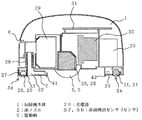
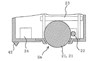
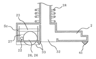
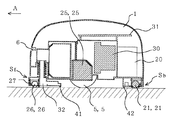
図1は本発明に係る自走式掃除機の概略構成を示す縦断面図、図2はその要部である本体最後部側の補助輪部分を拡大して示す部分断面図、図3はその要部である本体最前部側の補助輪部分を拡大して示す部分断面図、図4はその床ノズルの下部の正面図、図5はその前進動作の説明図、図6はその前方の床面段差検出の動作の説明図、図7はその後方の床面段差検出の動作の説明図である。
【0013】
本実施形態の自走式掃除機は、本体1の下面側の最前部に、コイルばね28により床面に対し常時押し付けられて床面との間隔が一定となるように保持された床ノズル2が設置されているとともに、その中央部に、駆動輪5とこれを駆動する減速機付きモータ25が配置され、その後方に、ゴミを吸い込むための風力を発生させる動力となる電動送風機30が設置されている。さらに、本体1内の電動送風機30の後方には、減速機付きモータ25や電動送風機30などの動力源となる充電池20が収納されている。また、本体1内の床ノズル2と電動送風機30の間には、床ノズル2より吸い込まれたゴミを採取し、収納しておく紙パック29が配置されているとともに、本体1内の上部空間に、制御回路基板31が横向きに配置固定されている。なお、駆動輪5及び減速機付きモータ25の組合せが、図示していないがもう1組対向して設置されており、これら2組の駆動輪5及び減速機付きモータ25の回転方向によって、本体1の前進、後進、左旋回、右旋回等の運動が決定されるようになっている。
【0014】
また、本体1の前端面側には、本体正面前方の障害物を検出するための超音波センサからなる障害物センサ6が設置されている。なお、障害物センサ6は、超音波を送信する送信手段と、送信手段から放射されて障害物に反射した超音波を受信する受信手段を備えた送受信型の超音波センサや、送受信兼用型の超音波センサなどにより構成される。
【0015】
また、本体1の下面側の少なくとも最前部と最後部、すなわち床ノズル2の前縁部の左右2隅と本体後縁部の2隅(後縁部については1隅のみ図示する)に、床面段差を検出する複数の床面検出センサSf,SfとSb,Sbが設けられている。
【0016】
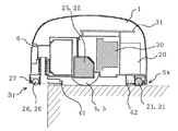
このうち最前部の床面検出センサSfは、図3及び図4のようにどの方向に対しても回転自在に設置されて床面と接触する球体26と、この球体26に接触して従動回転する2軸方向に配置されたローラ22,23と、これらローラ22,23の回転数を検出するロータリエンコーダ27とから成り、最前部において本体1の前後方向成分の動きをローラ22により、本体1の左右方向成分の動きをローラ23により、それぞれ検出するようになっている。
【0017】
最後部の床面検出センサSbも前記最前部の床面検出センサSfと同様に構成されている。すなわち、図2のようにどの方向に対しても回転自在に設置されて床面と接触する球体21と、この球体21に接触して従動回転する2軸方向に配置されたローラ22,23と、これらローラ22,23の回転数を検出するロータリエンコーダ24とから成り、最後部において本体1の前後方向成分の動きをローラ22により、本体1の左右方向成分の動きをローラ23により、それぞれ検出するようになっている。
【0018】
すなわち、前後の床面検出センサSf,Sbは、一般的なパーソナルコンピュータに使用されるマウスボールによるトラッキングメカニズムと同様な構成を有しており、床面上であれば本体1がどの方向に移動しても、その移動方向を前後方向の成分と左右方向の成分とに分解して確実に検出することができる。換言すれば、本体1が移動しているにも拘わらず床面検出センサSf,Sbが反応しないことを検出することで、走行面となる床面がなくなった状態、つまり床面段差があることを確実に検出できるようになっている。
【0019】
また、ここでは前後の床面検出センサSf,Sbよりも内方、つまり最前部の床面検出センサSfが取り付けられている床ノズル2の後縁部と最後部の床面検出センサSbの取付部の前縁部に、これらセンサSf,Sbの球体の取付部下面からの突出量よりも小さい突出量に設定された突起41,42を設け、各センサSf,Sbの球体26,21が、図6又は図7のように床面段差にあって浮いている状態下では、浮いている側の突起41又は42が支持脚となり、本体1が左右の駆動輪5,5を支点として床面段差側に傾くのを防ぐことができるようにしている。そして、各センサSf,Sbの球体26,21は、通常の床面上では左右の駆動輪5,5と共に本体1を前後で支持する補助輪として機能するようにしている。これにより、駆動輪5,5を本体中央部の左右のみの2輪構成とすることができ、本体前後方向の寸法を圧縮することができるようにしている。
【0020】
また、床ノズル側の左右の床面検出センサSf,Sfの各球体26,26の周りに、図3、図4のようにそれぞれ球体26,26を風路32から遮蔽する壁33,33を設け、これによって球体26,26へのゴミの絡みつきを減少させ、球体26,26のロック等の異常検出を防止して、安定した床面段差検出を可能としている。
【0021】
本体1内の上部空間に配置固定した制御回路基板31は、障害物センサ6から信号を受け取り、実装された演算回路により、障害物の有無を判定し、障害物の回避運動を制御する機能を有する。制御回路基板31は、この他にも、ロータリエンコーダ27,24の信号から床面段差の有無を判定し、床面段差の回避運動を制御する機能を有し、さらに電動送風機30の回転を制御する機能を有している。
【0022】
次に、本実施形態の自走式掃除機の動作について図5乃至図7により説明する。図5において、障害物センサ6により取得された信号は、制御回路基板31に送られる。制御回路基板31に実装された演算回路にて障害物無しと判定されると、本体1が図5の矢印Aの方向へ前進する。この移動により補助輪としても機能する前後左右の床面検出センサSf,Sf,Sb,Sbの各球体26,26,21,21は、床面との接触抵抗により回転する。もちろん本体1が移動を停止した場合は、各球体26,26,21,21共に回転を停止することになる。床ノズル側の球体26,26が回転しているかどうかは、ロータリエンコーダ27により検出することができる。床ノズル側球体26,26が回転しているということは、すなわち床ノズル側球体26,26と床面が接触しているということになり、本体1の進行方向、つまり矢印Aの方向に床面段差がないということを示している。その結果、本体1は継続して前進を行う。
【0023】
床ノズル側の球体26,26の周りには、図3、図4のように風路32から遮蔽する壁33,33を設けているため、ゴミは床ノズル側の球体26,26の付近を通らず、床ノズル側球体26,26にゴミが絡み付くのが防止される。このため、床ノズル側球体26,26の回転は、ゴミの絡み付きによってロックすることがなく、床面に接触していれば、確実に回転することができる。
【0024】
前進を継続中に、図6のように床ノズル側球体26,26が床面段差にかかり、浮いた状態となり、代わりに突起41によって支持された状態となった場合、床ノズル側球体26,26は床面と接触していないので、回転することができなくなる。床ノズル側球体26,26の回転数は、ロータリエンコーダ27にて検出され、その信号は制御回路基板31へ伝達される。制御回路基板31では、減速機付きモータ25,25に対して駆動指令を出していて、後方の本体側球体21,21のロータリエンコーダ24から球体21,21が回転している信号が入力しているにも拘わらず前方のロータリエンコーダ27から0回転の信号が入力すると、前方に床面段差有りと判定し、前進を直ちに止めさせ、左旋回、右旋回、後進等の回避運動を行なわせ、掃除機本体1の床面段差への転落を防止する。
【0025】
補助輪として機能する床ノズル側の球体26,26は、本体1の最前部に配置された床ノズル2の前縁部に配置されているので、すばやく床面段差を検出することができる。この結果、本体1の重心が床面段差と離れた位置にある段階ですばやく停止動作が行われ、次の回避動作へ移行することができる。このため、回避運動中に掃除機本体1が床面段差へ転落することがない。
【0026】
次に、本体後進中に、図7のように本体側球体21,21が床面段差にかかり、浮いた状態となり、代わりに突起42によって支持された状態となった場合の動作について説明する。この状態では、本体側球体21,21は床面と接触していないので、回転することができなくなる。本体側球体21,21の回転数は、ロータリエンコーダ24にて検出され、その信号は制御回路基板31へ伝達される。制御回路基板31では、減速機付きモータ25,25に対して駆動指令を出していて、反対側の床ノズル側球体26,26のロータリエンコーダ27から球体26,26が回転している信号が入力しているにも拘わらず後方(この場合は進行方向で前方となる)のロータリエンコーダ24から0回転の信号が入力すると、後方に床面段差有りと判定し、後進を直ちに止めさせ、左旋回、右旋回、前進等の回避運動を行なわせ、掃除機本体1の床面段差への転落を防止する。
【0027】
補助輪として機能する本体側の球体21,21は、本体1の最後部に配置されているので、すばやく床面段差を検出することができる。この結果、本体1の重心が床面段差と離れた位置にある段階ですばやく停止動作が行われ、次の回避動作へ移行することができる。このため、回避運動中に掃除機本体1が床面段差へ転落することがない。
【0028】
次に、本体1が旋回(例えば左旋回)中に、本体1の左旋回方向、つまり本体1の左側に床面段差があり、左側の床ノズル側球体26が床面段差にかかり、浮いた状態となり、代わりに突起41と右側の床ノズル側球体26によって支持された状態となった場合の動作について説明する。この状態では、左側の床ノズル側球体26は床面と接触していないので、回転することができなくなる。左側の床ノズル側球体26の回転数は、左側のロータリエンコーダ27にて検出され、その信号は制御回路基板31へ伝達される。制御回路基板31では、減速機付きモータ25,25に対して駆動指令を出していて、右側の床ノズル側球体26のロータリエンコーダ27と後方の本体側球体21,21の各ロータリエンコーダ24からそれぞれ右側の床ノズル側球体26と本体側球体21,21が回転している信号が入力しているにも拘わらず前方の左側のロータリエンコーダ27から0回転の信号が入力すると、床面段差有りと判定し、前進を直ちに止めさせ、右旋回、後進等の回避運動を行なわせ、掃除機本体1の床面段差への転落を防止する。もちろん、この動作は右旋回中についても同様である。
【0029】
補助輪として機能する床ノズル側の球体26,26及び本体側の球体21,21は、床ノズル2の前縁部の左右2隅と本体1の最後部の左右2隅にそれぞれ配置されているので、旋回中においてもすばやく床面段差を検出することができる。この結果、本体1の重心が床面段差と離れた位置にある段階ですばやく停止動作が行われ、次の回避動作へ移行することができる。このため、回避運動中に掃除機本体1が床面段差へ転落することがない。
【0030】
【発明の効果】
以上述べたように、本発明によれば、どの方向に対しても回転自在に設置されて床面と接触する球体、この球体に接触して従動回転する2軸方向に配置されたローラ、及びこれらローラの回転を検出するロータリエンコーダからなり、掃除機本体の下面側の最前部と最後部に配置されて床面段差を検出する複数の床面検出センサと、各床面検出センサの球体を、駆動輪と共に掃除機本体を支持する補助輪として構成できるように、床面検出センサの球体の取付部下面からの突出量よりも小さい突出量に設定されて前後の床面検出センサよりも内方に配置された複数の突起と、ロータリエンコーダの信号から進行方向後方の前記球体が回転しているにも拘わらず進行方向前方の前記球体が回転していない場合に、進行方向前方に床面段差有りと判定し、進行を直ちに止めさせ、床面段差の回避運動を行なわせる制御手段とを設けたので、掃除機本体の進行方向に対する床面段差を掃除機本体の下面側の進行方向で前方に位置する床面検出センサの球体の回転停止によりすばやく検出することができて、掃除機本体の重心が床面段差から離れた位置にあり、かつ床面段差側の球体が突起に支持されて浮いている状態にある段階で掃除機本体を停止させ、次の回避動作へ移行させることができた。このため、安全に回避運動へ移行することができて、掃除機本体の床面段差への転落を確実に防止することができた。
【図面の簡単な説明】
【図1】 本発明の一実施形態に係る自走式掃除機の概略構成を示す縦断面図である。
【図2】 本実施形態に係る自走式掃除機の要部である本体最後部側の補助輪部分を拡大して示す部分断面図である。
【図3】 本実施形態に係る自走式掃除機の要部である本体最前部側の補助輪部分を拡大して示す部分断面図である。
【図4】 本実施形態に係る自走式掃除機の床ノズルの下部の正面図である。
【図5】 本実施形態に係る自走式掃除機の前進動作の説明図である。
【図6】 本実施形態に係る自走式掃除機の前方の床面段差検出の動作の説明図である。
【図7】 本実施形態に係る自走式掃除機の後方の床面段差検出の動作の説明図である。
【符号の説明】
1 掃除機本体、2 床ノズル、5 駆動輪、20 充電池、Sf,Sb 床面検出センサ(センサ)。[0001]
BACKGROUND OF THE INVENTION
The present invention relates to a self-propelled cleaner that has a self-supporting traveling function and a cleaning function and performs automatic cleaning.
[0002]
[Prior art]
2. Description of the Related Art Conventionally, a vacuum cleaner has been developed that adds a self-supporting traveling function to a vacuum cleaner to improve operability during cleaning. In recent years, a so-called self-propelled self-propelled cleaner, which is equipped with a microcomputer and various sensors, has been developed recently.
[0003]
This type of self-propelled vacuum cleaner has a floor nozzle, a rotating brush, etc. at the bottom of the main body as a cleaning function, and has traveling wheels and steering wheels driven by a motor as a moving function, and a rechargeable battery as a power supply means. It has a position recognizing means for recognizing the position of the main body and an obstacle detecting means for detecting an obstacle at the time of traveling to move and clean the area within the cleaning area.
[0004]
Further, while the main body is running, a floor surface level difference is detected by detecting the number of rotations of the rotating brush and the current value of the rotating brush motor, and an avoidance motion is performed (for example, see Patent Document 1).
[0005]
[Patent Document 1]
Japanese Patent Laid-Open No. 8-517
[Problems to be solved by the invention]
However, in the case where the floor level difference is detected from the rotational speed of the rotary brush and the current value of the rotary brush motor, even if the floor nozzle is arranged at the frontmost part of the lower surface of the cleaner body, The suction port (air passage) is at a position shifted backward from the front edge of the cleaner body. And since the rotating brush attached to this is generally arranged at the center of the suction port (air passage) of the floor nozzle, the detection of the floor surface step is delayed by the amount displaced inward from the front edge of the main body. End up. If the detection of the floor level difference is delayed, the main body will continue to advance during that time, so when it stops, a part of the main body will hit the floor level difference, and the center of gravity of the main body will approach the floor level difference accordingly. Become. The avoidance movement from this state involves danger, and in the worst case, the avoidance movement may fall from the floor level difference.
[0007]
In addition, the rotating brush is provided only in front of the main body, and when the main body moves backward, if there is a floor level difference behind the main body, the level difference cannot be detected and the main body may fall from the floor level difference.
[0008]
Further, as described above, the rotating brush is often provided in the suction port (air passage) of the floor nozzle, that is, the passage of the dust, and the dust is easily entangled. If dust gets entangled with the rotating brush, the rotation of the rotating brush will be locked, and even if the rotating brush hits the floor step, it will not run idle, and it may detect an abnormality rather than the original operation of detecting the floor step. There is.
[0009]
The technical problem of the present invention is to enable quick detection of a floor level difference and to surely prevent the vacuum cleaner body from falling to a floor level difference.
[0010]
[Means for Solving the Problems]
The self-propelled cleaner according to the present invention has the following configuration. That is, in a self-propelled cleaner equipped with a rechargeable battery and equipped with a self-propelled traveling function by a drive wheel and a cleaning function by a floor nozzle , a sphere that is rotatably installed in any direction and contacts the floor surface, 2 axially arranged rollers driven to rotate in contact with the sphere, and consists rotary encoder for detecting the rotation of these rollers, the lower surface forefront and is in floor level difference is placed at the end portion of the cleaner body A plurality of floor surface detection sensors to be detected and the spheres of each floor surface detection sensor can be configured as auxiliary wheels that support the cleaner body together with the drive wheels, and the amount of protrusion from the bottom surface of the sphere mounting portion of the floor surface detection sensor A plurality of protrusions set inwardly from the front and rear floor detection sensors and the sphere behind the direction of travel from the signal of the rotary encoder. When the sphere toward the front is not rotating, it is determined that there is a floor step ahead in the traveling direction, immediately stop allowed to progress, in which a control means for causing the avoidance movement of the floor step.
[0011]
In the self-propelled cleaner of the present invention, when the floor surface that becomes the traveling surface is removed directly under the state in which the cleaner body is moving, the floor surface that is positioned forward in the traveling direction on the lower surface side of the cleaner body Since the rotation of the sphere of the detection sensor stops, it is immediately detected that there is a floor step in the forward direction of travel, and the cleaner body stops. At this time, the center of gravity of the body Ri enough away near the floor level difference, and the sphere of the floor step side is in a state of floating and is supported by the protrusion. For this reason, it can transfer to an avoidance exercise | movement safely and can prevent falling to the floor surface level | step difference of a cleaner main body reliably.
[0012]
DETAILED DESCRIPTION OF THE INVENTION
FIG. 1 is a longitudinal sectional view showing a schematic configuration of a self-propelled cleaner according to the present invention, FIG. 2 is an enlarged partial sectional view showing an auxiliary wheel portion on the rear end side of the main body, which is the main part, and FIG. FIG. 4 is a front view of a lower portion of the floor nozzle, FIG. 5 is an explanatory view of the forward movement operation, and FIG. 6 is a floor in front of the main body. FIG. 7 is an explanatory diagram of the operation of detecting the surface level difference, and FIG.
[0013]
The self-propelled cleaner of the present embodiment is a
[0014]
Further, an obstacle sensor 6 composed of an ultrasonic sensor for detecting an obstacle in front of the main body is installed on the front end face side of the main body 1. The obstacle sensor 6 is a transmission / reception type ultrasonic sensor including a transmission unit that transmits ultrasonic waves and a reception unit that receives ultrasonic waves emitted from the transmission unit and reflected by the obstacles. An ultrasonic sensor is used.
[0015]
In addition, at least the foremost part and the rearmost part on the lower surface side of the main body 1, that is, the left and right corners of the front edge part of the
[0016]
Among these, the foremost floor surface detection sensor Sf is installed so as to be rotatable in any direction as shown in FIGS. 3 and 4, and a
[0017]
The rearmost floor surface detection sensor Sb is configured similarly to the frontmost floor surface detection sensor Sf. That is, as shown in FIG. 2, a sphere 21 that is rotatably installed in any direction and is in contact with the floor surface, and
[0018]
That is, the front and rear floor surface detection sensors Sf and Sb have the same configuration as the tracking mechanism using a mouse ball used in a general personal computer, and in which direction the main body 1 moves on the floor surface. Even so, the moving direction can be decomposed into the front-rear direction component and the left-right direction component and reliably detected. In other words, by detecting that the floor surface detection sensors Sf and Sb do not react even though the main body 1 is moving, there is no floor surface as a traveling surface, that is, there is a floor surface step. Can be reliably detected.
[0019]
In addition, here, the inner side of the front and rear floor surface detection sensors Sf and Sb, that is, the rear edge of the
[0020]
Further, around the
[0021]
The
[0022]
Next, the operation of the self-propelled cleaner according to the present embodiment will be described with reference to FIGS. In FIG. 5, the signal acquired by the obstacle sensor 6 is sent to the
[0023]
Since the
[0024]
If the floor
[0025]
Since the
[0026]
Next, the operation in the case where the main body side spheres 21 and 21 are placed on the floor level difference as shown in FIG. 7 and floated while being supported by the
[0027]
Since the spheres 21 and 21 on the main body side that function as auxiliary wheels are arranged at the rearmost part of the main body 1, it is possible to quickly detect a floor level difference. As a result, when the center of gravity of the main body 1 is at a position away from the floor surface step, the stop operation is quickly performed, and it is possible to shift to the next avoidance operation. For this reason, the vacuum cleaner main body 1 does not fall to the floor level difference during the avoidance exercise.
[0028]
Next, while the main body 1 is turning (for example, left turning), there is a step difference in the left turning direction of the main body 1, that is, the left side of the main body 1, and the left floor
[0029]
The floor nozzle-
[0030]
【The invention's effect】
As described above, according to the present invention, a sphere that is rotatably installed in any direction and is in contact with the floor surface, a roller disposed in a biaxial direction that is rotated in contact with the sphere, and It consists of a rotary encoder that detects the rotation of these rollers, and is arranged at the foremost part and the rearmost part on the lower surface side of the vacuum cleaner main body to detect a plurality of floor surface detection sensors, and a sphere of each floor surface detection sensor. In addition, it can be configured as an auxiliary wheel that supports the vacuum cleaner body together with the drive wheel, and is set to a projection amount smaller than the projection amount from the bottom surface of the sphere mounting portion of the floor surface detection sensor, and is inward of the front and rear floor surface detection sensors. A plurality of protrusions arranged in the direction and a floor surface in front of the traveling direction when the sphere forward in the traveling direction is not rotated despite the rotation of the sphere behind the traveling direction from the signal of the rotary encoder. With steps Constant was immediately stopped allowed to proceed, since there is provided a control means for causing the avoidance movement of the floor steps, located in front of the floor step with respect to the traveling direction of the cleaner body in the traveling direction of the lower surface side of the cleaner body able to quickly detect the rotation stop of the sphere of the floor detection sensor, the center of gravity of the cleaner main body Ri position near away from the floor level difference, and in the sphere of the floor step side is supported by the protrusion floats to The vacuum cleaner main body was stopped at the stage where it was in a state where it was possible to shift to the next avoidance operation. Therefore, it is possible to shift to safely avoid exercise, it was possible to reliably prevent falling to the floor level difference of the cleaner body.
[Brief description of the drawings]
FIG. 1 is a longitudinal sectional view showing a schematic configuration of a self-propelled cleaner according to an embodiment of the present invention.
FIG. 2 is an enlarged partial cross-sectional view showing an auxiliary wheel portion on the rearmost side of the main body, which is a main part of the self-propelled cleaner according to the present embodiment.
FIG. 3 is an enlarged partial cross-sectional view showing an auxiliary wheel portion on the forefront side of the main body, which is a main part of the self-propelled cleaner according to the present embodiment.
FIG. 4 is a front view of the lower part of the floor nozzle of the self-propelled cleaner according to the present embodiment.
FIG. 5 is an explanatory diagram of a forward movement operation of the self-propelled cleaner according to the present embodiment.
FIG. 6 is an explanatory diagram of an operation for detecting a floor level difference in front of the self-propelled cleaner according to the present embodiment.
FIG. 7 is an explanatory diagram of an operation of detecting a floor level difference behind the self-propelled cleaner according to the present embodiment.
[Explanation of symbols]
DESCRIPTION OF SYMBOLS 1 Vacuum cleaner main body, 2 Floor nozzle, 5 Drive wheel, 20 Rechargeable battery, Sf, Sb Floor surface detection sensor (sensor).
Claims (3)
どの方向に対しても回転自在に設置されて床面と接触する球体、この球体に接触して従動回転する2軸方向に配置されたローラ、及びこれらローラの回転を検出するロータリエンコーダからなり、掃除機本体の下面側の最前部と最後部に配置されて床面段差を検出する複数の床面検出センサと、
各前記床面検出センサの球体を、前記駆動輪と共に掃除機本体を支持する補助輪として構成できるように、前記床面検出センサの球体の取付部下面からの突出量よりも小さい突出量に設定されて前後の床面検出センサよりも内方に配置された複数の突起と、
前記ロータリエンコーダの信号から進行方向後方の前記球体が回転しているにも拘わらず進行方向前方の前記球体が回転していない場合に、進行方向前方に床面段差有りと判定し、進行を直ちに止めさせ、床面段差の回避運動を行なわせる制御手段とを備えることを特徴とする自走式掃除機。In a self-propelled cleaner equipped with a rechargeable battery and equipped with a self-propelled running function with a drive wheel and a cleaning function with a floor nozzle,
It consists of a sphere that is freely rotatable in any direction and is in contact with the floor surface, a roller arranged in a biaxial direction in contact with the sphere and driven to rotate, and a rotary encoder that detects the rotation of these rollers. A plurality of floor surface detection sensors arranged at the forefront and rearmost part of the lower surface side of the vacuum cleaner body to detect a floor surface step ;
The sphere of each of the floor surface detection sensors is set to a projection amount smaller than the projection amount from the bottom surface of the sphere mounting portion of the sphere detection sensor so that it can be configured as an auxiliary wheel that supports the cleaner body together with the drive wheels. A plurality of protrusions disposed inward than the front and back floor detection sensors;
When the sphere behind the traveling direction is rotating from the signal of the rotary encoder but the sphere ahead in the traveling direction is not rotating, it is determined that there is a step difference in the front in the traveling direction, and the progress is immediately A self-propelled cleaner characterized by comprising a control means for stopping and performing an avoiding movement of a floor level difference .
Priority Applications (1)
| Application Number | Priority Date | Filing Date | Title |
|---|---|---|---|
| JP2002363541A JP4069293B2 (en) | 2002-12-16 | 2002-12-16 | Self-propelled vacuum cleaner |
Applications Claiming Priority (1)
| Application Number | Priority Date | Filing Date | Title |
|---|---|---|---|
| JP2002363541A JP4069293B2 (en) | 2002-12-16 | 2002-12-16 | Self-propelled vacuum cleaner |
Publications (2)
| Publication Number | Publication Date |
|---|---|
| JP2004194715A JP2004194715A (en) | 2004-07-15 |
| JP4069293B2 true JP4069293B2 (en) | 2008-04-02 |
Family
ID=32761661
Family Applications (1)
| Application Number | Title | Priority Date | Filing Date |
|---|---|---|---|
| JP2002363541A Expired - Fee Related JP4069293B2 (en) | 2002-12-16 | 2002-12-16 | Self-propelled vacuum cleaner |
Country Status (1)
| Country | Link |
|---|---|
| JP (1) | JP4069293B2 (en) |
Cited By (3)
| Publication number | Priority date | Publication date | Assignee | Title |
|---|---|---|---|---|
| WO2013047073A1 (en) * | 2011-09-29 | 2013-04-04 | シャープ株式会社 | Cleaning robot |
| JP2013070951A (en) * | 2011-09-29 | 2013-04-22 | Sharp Corp | Cleaning robot |
| JP2013070952A (en) * | 2011-09-29 | 2013-04-22 | Sharp Corp | Cleaning robot |
Families Citing this family (5)
| Publication number | Priority date | Publication date | Assignee | Title |
|---|---|---|---|---|
| ATE534941T1 (en) | 2005-12-02 | 2011-12-15 | Irobot Corp | COVER ROBOT MOBILITY |
| EP2816434A3 (en) * | 2005-12-02 | 2015-01-28 | iRobot Corporation | Autonomous coverage robot |
| KR100683074B1 (en) * | 2005-12-22 | 2007-02-15 | (주)경민메카트로닉스 | Robot cleaner |
| KR101168481B1 (en) | 2007-05-09 | 2012-07-26 | 아이로보트 코퍼레이션 | Autonomous coverage robot |
| JP7466109B2 (en) * | 2018-10-15 | 2024-04-12 | パナソニックIpマネジメント株式会社 | Mobile |
-
2002
- 2002-12-16 JP JP2002363541A patent/JP4069293B2/en not_active Expired - Fee Related
Cited By (3)
| Publication number | Priority date | Publication date | Assignee | Title |
|---|---|---|---|---|
| WO2013047073A1 (en) * | 2011-09-29 | 2013-04-04 | シャープ株式会社 | Cleaning robot |
| JP2013070951A (en) * | 2011-09-29 | 2013-04-22 | Sharp Corp | Cleaning robot |
| JP2013070952A (en) * | 2011-09-29 | 2013-04-22 | Sharp Corp | Cleaning robot |
Also Published As
| Publication number | Publication date |
|---|---|
| JP2004194715A (en) | 2004-07-15 |
Similar Documents
| Publication | Publication Date | Title |
|---|---|---|
| JP5048663B2 (en) | Robot cleaning device | |
| US9668627B2 (en) | Robot cleaner | |
| KR101613106B1 (en) | Drive arrangement for a mobile robot | |
| KR101571381B1 (en) | Autonomous vacuum cleaner | |
| JP2005021665A (en) | Driving device of robot cleaner | |
| JP2003280740A (en) | Movable device | |
| JPH05228090A (en) | Self-traveling type cleaner | |
| JP4069293B2 (en) | Self-propelled vacuum cleaner | |
| JP3339185B2 (en) | Mobile work robot | |
| JP2017153787A (en) | Self-travel type vacuum cleaner | |
| KR20160035366A (en) | Robot Cleaner | |
| JPH0351023A (en) | Self-propelled cleaner | |
| JP2018130198A (en) | Self-traveling type vacuum cleaner | |
| JP2007179398A (en) | Self-propelled cleaner | |
| JP2007244722A (en) | Self-propelled vacuum cleaner | |
| JP2006087508A (en) | Self-propelled cleaner | |
| KR101397103B1 (en) | Robot cleaner and method for controlling travel the same | |
| JP6509479B2 (en) | Electric vacuum cleaner | |
| JP2007334667A (en) | Self-propelled vacuum cleaner | |
| JP2669071B2 (en) | Self-propelled vacuum cleaner | |
| KR100783156B1 (en) | Robot cleaner | |
| JP2004049592A (en) | Self-propelled vacuum cleaner | |
| JP6155784B2 (en) | Self-propelled vacuum cleaner | |
| KR101489512B1 (en) | A Robot cleaner with enhanced steering ability and the driving method | |
| KR100213491B1 (en) | Safety device for automatic vacuum cleaner |
Legal Events
| Date | Code | Title | Description |
|---|---|---|---|
| A621 | Written request for application examination |
Free format text: JAPANESE INTERMEDIATE CODE: A621 Effective date: 20050114 |
|
| A977 | Report on retrieval |
Free format text: JAPANESE INTERMEDIATE CODE: A971007 Effective date: 20071011 |
|
| A131 | Notification of reasons for refusal |
Free format text: JAPANESE INTERMEDIATE CODE: A131 Effective date: 20071016 |
|
| A521 | Request for written amendment filed |
Free format text: JAPANESE INTERMEDIATE CODE: A523 Effective date: 20071122 |
|
| TRDD | Decision of grant or rejection written | ||
| A01 | Written decision to grant a patent or to grant a registration (utility model) |
Free format text: JAPANESE INTERMEDIATE CODE: A01 Effective date: 20071225 |
|
| A61 | First payment of annual fees (during grant procedure) |
Free format text: JAPANESE INTERMEDIATE CODE: A61 Effective date: 20071227 |
|
| R150 | Certificate of patent or registration of utility model |
Free format text: JAPANESE INTERMEDIATE CODE: R150 Ref document number: 4069293 Country of ref document: JP Free format text: JAPANESE INTERMEDIATE CODE: R150 |
|
| FPAY | Renewal fee payment (event date is renewal date of database) |
Free format text: PAYMENT UNTIL: 20110125 Year of fee payment: 3 |
|
| FPAY | Renewal fee payment (event date is renewal date of database) |
Free format text: PAYMENT UNTIL: 20120125 Year of fee payment: 4 |
|
| FPAY | Renewal fee payment (event date is renewal date of database) |
Free format text: PAYMENT UNTIL: 20130125 Year of fee payment: 5 |
|
| FPAY | Renewal fee payment (event date is renewal date of database) |
Free format text: PAYMENT UNTIL: 20130125 Year of fee payment: 5 |
|
| R250 | Receipt of annual fees |
Free format text: JAPANESE INTERMEDIATE CODE: R250 |
|
| R250 | Receipt of annual fees |
Free format text: JAPANESE INTERMEDIATE CODE: R250 |
|
| R250 | Receipt of annual fees |
Free format text: JAPANESE INTERMEDIATE CODE: R250 |
|
| R250 | Receipt of annual fees |
Free format text: JAPANESE INTERMEDIATE CODE: R250 |
|
| R250 | Receipt of annual fees |
Free format text: JAPANESE INTERMEDIATE CODE: R250 |
|
| LAPS | Cancellation because of no payment of annual fees |