JP2016512733A - System and method using zero space to anisotropically enhance manipulator joint motion - Google Patents
System and method using zero space to anisotropically enhance manipulator joint motion Download PDFInfo
- Publication number
- JP2016512733A JP2016512733A JP2016502607A JP2016502607A JP2016512733A JP 2016512733 A JP2016512733 A JP 2016512733A JP 2016502607 A JP2016502607 A JP 2016502607A JP 2016502607 A JP2016502607 A JP 2016502607A JP 2016512733 A JP2016512733 A JP 2016512733A
- Authority
- JP
- Japan
- Prior art keywords
- joint
- joints
- end effector
- manipulator
- space
- Prior art date
- Legal status (The legal status is an assumption and is not a legal conclusion. Google has not performed a legal analysis and makes no representation as to the accuracy of the status listed.)
- Pending
Links
Images


Classifications
-
- A—HUMAN NECESSITIES
- A61—MEDICAL OR VETERINARY SCIENCE; HYGIENE
- A61B—DIAGNOSIS; SURGERY; IDENTIFICATION
- A61B34/00—Computer-aided surgery; Manipulators or robots specially adapted for use in surgery
- A61B34/30—Surgical robots
- A61B34/37—Master-slave robots
-
- A—HUMAN NECESSITIES
- A61—MEDICAL OR VETERINARY SCIENCE; HYGIENE
- A61B—DIAGNOSIS; SURGERY; IDENTIFICATION
- A61B1/00—Instruments for performing medical examinations of the interior of cavities or tubes of the body by visual or photographical inspection, e.g. endoscopes; Illuminating arrangements therefor
- A61B1/00163—Optical arrangements
- A61B1/00193—Optical arrangements adapted for stereoscopic vision
-
- A—HUMAN NECESSITIES
- A61—MEDICAL OR VETERINARY SCIENCE; HYGIENE
- A61B—DIAGNOSIS; SURGERY; IDENTIFICATION
- A61B18/00—Surgical instruments, devices or methods for transferring non-mechanical forms of energy to or from the body
- A61B18/04—Surgical instruments, devices or methods for transferring non-mechanical forms of energy to or from the body by heating
- A61B18/12—Surgical instruments, devices or methods for transferring non-mechanical forms of energy to or from the body by heating by passing a current through the tissue to be heated, e.g. high-frequency current
- A61B18/14—Probes or electrodes therefor
-
- A—HUMAN NECESSITIES
- A61—MEDICAL OR VETERINARY SCIENCE; HYGIENE
- A61B—DIAGNOSIS; SURGERY; IDENTIFICATION
- A61B34/00—Computer-aided surgery; Manipulators or robots specially adapted for use in surgery
- A61B34/25—User interfaces for surgical systems
-
- A—HUMAN NECESSITIES
- A61—MEDICAL OR VETERINARY SCIENCE; HYGIENE
- A61B—DIAGNOSIS; SURGERY; IDENTIFICATION
- A61B34/00—Computer-aided surgery; Manipulators or robots specially adapted for use in surgery
- A61B34/30—Surgical robots
-
- B—PERFORMING OPERATIONS; TRANSPORTING
- B25—HAND TOOLS; PORTABLE POWER-DRIVEN TOOLS; MANIPULATORS
- B25J—MANIPULATORS; CHAMBERS PROVIDED WITH MANIPULATION DEVICES
- B25J18/00—Arms
- B25J18/007—Arms the end effector rotating around a fixed point
-
- B—PERFORMING OPERATIONS; TRANSPORTING
- B25—HAND TOOLS; PORTABLE POWER-DRIVEN TOOLS; MANIPULATORS
- B25J—MANIPULATORS; CHAMBERS PROVIDED WITH MANIPULATION DEVICES
- B25J9/00—Programme-controlled manipulators
- B25J9/16—Programme controls
- B25J9/1602—Programme controls characterised by the control system, structure, architecture
- B25J9/1607—Calculation of inertia, jacobian matrixes and inverses
-
- A—HUMAN NECESSITIES
- A61—MEDICAL OR VETERINARY SCIENCE; HYGIENE
- A61B—DIAGNOSIS; SURGERY; IDENTIFICATION
- A61B18/00—Surgical instruments, devices or methods for transferring non-mechanical forms of energy to or from the body
- A61B2018/00571—Surgical instruments, devices or methods for transferring non-mechanical forms of energy to or from the body for achieving a particular surgical effect
- A61B2018/00595—Cauterization
Landscapes
- Engineering & Computer Science (AREA)
- Health & Medical Sciences (AREA)
- Life Sciences & Earth Sciences (AREA)
- Surgery (AREA)
- Robotics (AREA)
- Public Health (AREA)
- Veterinary Medicine (AREA)
- Nuclear Medicine, Radiotherapy & Molecular Imaging (AREA)
- Biomedical Technology (AREA)
- Heart & Thoracic Surgery (AREA)
- Medical Informatics (AREA)
- Molecular Biology (AREA)
- Animal Behavior & Ethology (AREA)
- General Health & Medical Sciences (AREA)
- Physics & Mathematics (AREA)
- Mechanical Engineering (AREA)
- Automation & Control Theory (AREA)
- Mathematical Physics (AREA)
- Human Computer Interaction (AREA)
- Pathology (AREA)
- Optics & Photonics (AREA)
- Biophysics (AREA)
- Radiology & Medical Imaging (AREA)
- Plasma & Fusion (AREA)
- Otolaryngology (AREA)
- Manipulator (AREA)
- Manufacturing & Machinery (AREA)
- General Physics & Mathematics (AREA)
Abstract
マニピュレータの1又は複数の関節の所望の運動を提供しながら、マニピュレータのエンドエフェクタの指令運動を提供するための装置、システム、及び方法である。方法は、関節の第1のセットの所望の運動を提供するために、ゼロ空間内の関節運動を異方的に強調するように前記関節空間で重み付き行列を使用して重み付き関節速度を計算することを含む。方法は、疑似逆行列解を使用して所望のエンドエフェクタ運動を達成する関節速度を計算すること及び関節の第1のセットの所望の運動に対応する関節空間内のポテンシャル関数勾配を使用して計算された関節速度を調整することを含み得る。方法は、重み付き疑似逆行列解及びまた拡張ヤコビアン解の使用を含み得る。1又は複数の補助運動も、疑似逆行列解から計算される関節速度を使用して提供され得る。このような方法を用いるシステムのための様々な構成が本明細書に提供される。An apparatus, system, and method for providing a commanded motion of an end effector of a manipulator while providing a desired motion of one or more joints of the manipulator. The method uses a weighted matrix in the joint space to provide a weighted joint velocity so as to anisotropically emphasize the joint motion in zero space to provide a desired motion of the first set of joints. Including calculating. The method uses a pseudo inverse matrix solution to calculate the joint velocity to achieve the desired end effector motion and using the potential function gradient in the joint space corresponding to the desired motion of the first set of joints. Adjusting the calculated joint speed may be included. The method may include the use of a weighted pseudo inverse matrix solution and also an extended Jacobian solution. One or more auxiliary motions may also be provided using the joint velocities calculated from the pseudo inverse matrix solution. Various configurations for systems using such methods are provided herein.
Description
関連出願の相互参照
本出願は、2013年3月15日に出願され“Systems and Methods for Using the Null Space to Emphasize Manipulator Joint Motion Anisotropically”と題する米国仮特許出願第61/800,924号(代理人整理番号ISRG03870PROV/US)からの非仮出願であるとともに、同仮出願からの優先権を主張し、その全開示が参照により本出願に援用される。
CROSS REFERENCE TO RELATED APPLICATIONS This application is filed Mar. 15, 2013, entitled “Systems and Methods for Using the Null Space to Emphasize Manipulator Joint Joint Motion Anisotropical No. 61 / Ap. No. provisional number ISRG03870PROV / US) and claims priority from the provisional application, the entire disclosure of which is incorporated herein by reference.
本出願は概して、所有者が共通する次の出願:“Control of Medical Robotic System Manipulator About Kinematic Singularities”と題する、2009年6月30日に出願された米国特許出願第12/494,695号;“Master Controller Having Redundant Degrees of Freedom and Added Forces to Create Internal Motion”と題する、2009年3月17日に出願されたの米国特許出願第12/406,004号;“Software Center and Highly Configurable Robotic Systems for Surgery and Other Uses”と題する、2005年5月19日に出願された米国特許出願第11/133,423号(米国特許第8,004,229号);“Offset Remote Center Manipulator For Robotic Surgery”と題する、2004年9月30日に出願された米国特許出願第10/957,077号(米国特許第7,594,912号);“Master Having Redundant Degrees of Freedom”と題する、1999年9月17日に出願された米国特許出願第09/398,507号(米国特許第6,714,839号);“Manipulator Arm−to−Patient Collision Avoidance Using a Null−Space”と題する、2012年6月1日に出願された米国仮出願第61/654,755号;“System and Methods for Avoiding Collisions Between Manipulator Arms Using a Null−Space”と題する、2012年6月1日に出願された米国仮出願第61/654,773号;に関連し、これらの開示は、その全体が参照により本明細書に援用される。
This application is generally a US patent application Ser. No. 12 / 494,695, filed Jun. 30, 2009, entitled “Control of Medical Robotic Manipulator About Kinetic Singularities”, which has common ownership. US Patent Application No. 12 / 406,004, filed March 17, 2009, entitled “Master Controller Having Redundant Degress of Freedom and Added Forces to Create Internal Motion”; U.S. Patent Application No. 11 / 133,423 (U.S. Patent No. 8,004,229) filed May 19, 2005, entitled "ry and Other Uses"; "Offset Remote Center Manipulator For Robotic Surcharge" US patent application Ser. No. 10 / 957,077 filed Sep. 30, 2004 (US Pat. No. 7,594,912); entitled “Master Having Redundant Degree of Freedom”, September 17, 1999 US patent application Ser. No. 09 / 398,507 (US Pat. No. 6,714,839) filed on the same day; “Manipulator Arm-to-Patient Collation Avidance Usin U.S. Provisional Application No. 61 / 654,755, filed June 1, 2012, entitled “a Null-Space”; “System and Methods for Avoiding Collisions Between Manipulator Arms Using a Null-
本発明は、概して、改良された手術及び/又はロボット装置、システム、及び方法を提供する。 The present invention generally provides improved surgical and / or robotic devices, systems, and methods.
低侵襲医療技術は、診断又は外科手術中に損傷を受ける組織の量を低減させることを目的とし、それによって、患者の回復時間、不快感、及び有害な副作用を減少させる。何百万という「観血」又は従来の手術が、米国で毎年行われており、これらの手術の多くは、潜在的に低侵襲的な方法で行うことができる。しかしながら、比較的少数の手術のみが、低侵襲手術器具や技術の制限、及びそれら低侵襲手術器具や技術を習得するために必要な追加の外科的トレーニングに起因して、低侵襲技術を現在使用している。 Minimally invasive medical techniques aim to reduce the amount of tissue that is damaged during diagnosis or surgery, thereby reducing patient recovery time, discomfort, and adverse side effects. Millions of “open” or conventional surgery are performed annually in the United States, and many of these operations can be performed in a potentially minimally invasive manner. However, only a relatively small number of surgeries currently use minimally invasive techniques due to limitations of minimally invasive surgical instruments and techniques and the additional surgical training required to learn those minimally invasive surgical instruments and techniques doing.
手術で使用される低侵襲遠隔手術システムは、外科医の器用さを増大させるように、及び外科医が離れた場所から患者を手術することを可能にするように開発されている。遠隔手術は、手で機器を直接的に保持し且つ動かすのではなく、手術器具の動きを操作するために、外科医が、例えばサーボ機構等の遠隔制御装置のいくつかのフォームを使用するような手術システムの総称である。このような遠隔手術システムでは、外科医には、遠離れた場所における手術部位の画像が提供される。典型的には適切なビューア又はディスプレイ上で手術部位の三次元画像を見ながら、外科医は、マスタ制御入力装置を操作することによって、患者に外科手術を行い、このマスタ制御入力装置はロボット器具の動作を制御する。ロボット手術器具は、患者内の手術部位において組織を治療するために、小さな、低侵襲手術開口部、大抵、観血手術のためにアクセスすることと関連付けられる外傷、を介して挿入されることができる。これらのロボットシステムは、大抵、低侵襲開口部において器具シャフトを枢動、開口部を通じた軸方向のシャフトの摺動、開口部内でのシャフトの回転、及び/又は同様の動作によって、非常に複雑な外科的タスクを行うために十分な器用さで手術器具の作業端部を移動させることができる。 Minimally invasive telesurgical systems used in surgery have been developed to increase the surgeon's dexterity and allow the surgeon to operate on the patient from a remote location. Telesurgery is such that the surgeon uses some form of remote control device, such as a servomechanism, to manipulate the movement of the surgical instrument, rather than holding and moving the instrument directly by hand. A general term for surgical systems. In such a telesurgical system, the surgeon is provided with images of the surgical site at a remote location. While viewing a three-dimensional image of the surgical site, typically on a suitable viewer or display, the surgeon performs a surgical operation on the patient by manipulating the master control input device, which master control input device is Control the behavior. Robotic surgical instruments can be inserted through small, minimally invasive surgical openings, usually trauma associated with access for open surgery, to treat tissue at the surgical site within a patient it can. These robotic systems are often very complex by pivoting the instrument shaft in a minimally invasive opening, sliding the shaft axially through the opening, rotating the shaft within the opening, and / or similar movements. The working end of the surgical instrument can be moved with sufficient dexterity to perform a complex surgical task.
遠隔手術用に使用されるサーボ機構は、大抵、2つのマスタ制御装置(外科医の手の各々に対して1つ)からの入力を受け取り、そして2以上のロボットアーム又はマニピュレータを含み得る。画像取込装置によって表示されたロボット器具の画像への手の動きのマッピングは、それぞれの手に関連付けられた器具についての正確な制御を外科医に提供するのに役立つことができる。多くの手術ロボットシステムでは、1又は複数の追加のロボットマニピュレータアームが、内視鏡又は他の画像取込装置、追加の手術器具等を移動させるために含められる。 Servo mechanisms used for telesurgery typically receive input from two master controllers (one for each of the surgeon's hands) and may include two or more robotic arms or manipulators. The mapping of hand movements to images of robotic instruments displayed by the image capture device can help to provide the surgeon with precise control over the instruments associated with each hand. In many surgical robotic systems, one or more additional robotic manipulator arms are included to move an endoscope or other image capture device, additional surgical instruments, and the like.
様々な構造配置が、ロボットによる手術中に、手術器具を手術部位に支持するために、使用されることができる。従動リンク機構又は「スレーブ」は、大抵、ロボット手術マニピュレータと呼ばれており、低侵襲ロボット手術中にロボット手術マニピュレータとして使用される例示的なリンク機構配置は、特許文献1、特許文献2及び特許文献3に記載されており、これらの全体の開示は、参照により本明細書に援用される。これらのリンク機構は、大抵、シャフトを有する器具を保持するために、平行四辺形の配置を利用する。このようなマニピュレータ構造は、器具シャフトが、剛性シャフトの長さに沿った空間に位置する球状回転の遠隔センタの周りを枢動するように、器具の動きを拘束することができる。(例えば、腹腔鏡手術中、腹壁にトロカール又はカニューレを用いて)内部手術部位への切開点とこの回転の中心とを位置合わせすることによって、手術器具のエンドエフェクタは、腹壁に対して潜在的に危険な力を与えることなく、マニピュレータリンク機構を用いてシャフトの近位端部を移動させることによって、安全に位置決めされることができる。代替のマニピュレータ構造は、例えば、特許文献4、特許文献5、特許文献6、特許文献7、特許文献8、及び特許文献9に記載されており、これらの全体の開示は、参照により本明細書に援用される。
Various structural arrangements can be used to support the surgical instrument at the surgical site during robotic surgery. A driven link mechanism or “slave” is often referred to as a robotic surgical manipulator, and exemplary link mechanism arrangements used as robotic surgical manipulators during minimally invasive robotic surgery are described in US Pat. Reference 3 is incorporated by reference herein in its entirety. These linkages often utilize a parallelogram arrangement to hold an instrument having a shaft. Such a manipulator structure can constrain the movement of the instrument such that the instrument shaft pivots around a spherically rotating remote center located in space along the length of the rigid shaft. By aligning the incision point to the internal surgical site and the center of this rotation (eg, during laparoscopic surgery, using a trocar or cannula on the abdominal wall), the end effector of the surgical instrument is potentially relative to the abdominal wall. Can be safely positioned by moving the proximal end of the shaft using a manipulator linkage without inflicting dangerous forces on the shaft. Alternative manipulator structures are described, for example, in
新しいロボット手術システム及び装置は非常に効果的であり且つ有用であることが判明しているが、依然としてさらなる改良が望まれている。例えば、マニピュレータアームが、特定の状況下で、さらなる運動又は形態を提供するために、追加的な冗長関節を含む可能性がある。しかし、低侵襲手術部位内で手術器具を移動させるとき、これらの関節は、特に、大きい角度範囲に亘って低侵襲開口部の周りに器具を枢動させるときに、患者の体外でのかなりの量の動き、しばしば、必要とされる又は予想されるより大きい動きを示す可能性がある。患者の体外での不慮のマニピュレータ/マニピュレータ接触(等)を防止しながら挿入部位に対する枢動運動を拘束するように高度に設定可能な運動学的マニピュレータ関節セットに対するソフトウェア制御を用いる代替のマニピュレータ構造が提案されている。これらの代替の高度に設定可能な「ソフトウェアセンタ」手術マニピュレータシステムは、重要な利点を提供し得るが、課題も存在し得る。特に、機械的に拘束された遠隔センタリンク機構は、いくつかの条件で安全性に関する利点を有し得る。加えて、これらのマニピュレータに大抵含まれる多くの関節の広範囲の構成は、マニピュレータが、特定の処置に望ましい形態に手動で設定することが困難であることをもたらし得る。それにもかかわらず、遠隔手術システムを用いて行われる手術の範囲は拡大し続けているので、利用可能な構成及び患者内の器具の可動域を拡張するための要求が高まっている。残念ながら、これらの両方の変化は、体外のマニピュレータの動きに関連する課題を増大させ、また、幾つかのタスクに対するマニピュレータアームの過度の動きを避けることの重要性も高め得る。 Although new robotic surgical systems and devices have been found to be very effective and useful, further improvements are still desired. For example, the manipulator arm may include additional redundant joints to provide additional motion or form under certain circumstances. However, when moving a surgical instrument within a minimally invasive surgical site, these joints can be a significant amount outside the patient's body, particularly when pivoting the instrument around a minimally invasive opening over a large angular range. There can be a lot of movement, often showing more movement than needed or expected. An alternative manipulator structure that uses software control over a highly configurable kinematic manipulator joint set to constrain the pivoting motion relative to the insertion site while preventing accidental manipulator / manipulator contact (etc.) outside the patient's body Proposed. Although these alternative highly configurable “software center” surgical manipulator systems can provide significant advantages, challenges can also exist. In particular, a mechanically constrained remote center link mechanism may have safety advantages in some conditions. In addition, the extensive configuration of the many joints that are often included in these manipulators can result in the manipulator being difficult to manually set to the desired form for a particular procedure. Nevertheless, as the scope of surgery performed using telesurgical systems continues to expand, there is an increasing demand to expand the available configurations and the range of motion of the instruments within the patient. Unfortunately, both of these changes increase the challenges associated with extracorporeal manipulator movement and can also increase the importance of avoiding excessive movement of the manipulator arm for some tasks.
これらの及び他の理由のために、手術、ロボット手術及び他のロボット用途のための、改良された装置、システム、及び方法を提供することが有利であり、これらの改良された技術が、幾つかのタスクの間にマニピュレータアームの運動の量を制限する提供する能力を提供する場合には、それは特に有益である。加えて、それらの器用さを維持又は向上させたまま、寸法、機械的な複雑さ、又はこれらのシステムのコストを大幅に増加させることなく、少なくともいくつかのタスクに対して器具の動作範囲を増加させながら、このような改良を提供することが望ましい。 For these and other reasons, it would be advantageous to provide improved devices, systems, and methods for surgery, robotic surgery, and other robotic applications. It is particularly beneficial if it provides the ability to provide limiting the amount of manipulator arm movement during that task. In addition, while maintaining or improving their dexterity, the operating range of the instrument for at least some tasks without significantly increasing the size, mechanical complexity, or cost of these systems. It would be desirable to provide such improvements while increasing.
本発明は概して、改良されたロボット及び/又は手術装置、システム、及び方法を提供する。多くの実施形態では、本発明は、高度に設定可能な手術ロボットマニピュレータを用いる。これらのマニピュレータは、例えば、関連付けられる手術用エンドエフェクタが手術作業空間内で有するよりも、大きい運動の自由度を有し得る。本発明によるロボット手術システムは、典型的には、ロボット手術器具を支持するマニピュレータアーム、及び、器具のエンドエフェクタを操作するために協調関節運動を計算するためのプロセッサを含む。エンドエフェクタを支持するロボットマニピュレータの関節は、マニピュレータが、与えられたエンドエフェクタの位置及び/又は与えられた枢動(pivot)ポイント位置についての異なる形態の範囲に亘って動くことを可能にする。マニピュレータは、ユーザ指令に応じた再配置運動のような、様々な種類の補助運動、又は衝突回避運動のような、他の種類の運動を可能にするために、追加の冗長関節を含み得る。 The present invention generally provides improved robotic and / or surgical devices, systems, and methods. In many embodiments, the present invention uses a highly configurable surgical robot manipulator. These manipulators may have greater freedom of motion than, for example, the associated surgical end effector has in the surgical workspace. A robotic surgical system according to the present invention typically includes a manipulator arm that supports a robotic surgical instrument and a processor for calculating coordinated joint motion to operate the end effector of the instrument. The joint of the robot manipulator that supports the end effector allows the manipulator to move over a range of different configurations for a given end effector position and / or a given pivot point position. The manipulator may include additional redundant joints to allow various types of auxiliary movements, such as repositioning movements in response to user commands, or other types of movements, such as collision avoidance movements.
1つの態様では、本発明は、ユーザ入力エンドエフェクタ操作指令に応じて所望のエンドエフェクタ運動を生じさせながら、体外のマニピュレータの1又は複数の関節の所望の運動を提供するように、ゼロ空間異方性(null−space anisotropically)内でマニピュレータの1又は複数の関節の動作の強調を可能にする。関節動作の強調は、それが関節の方向に依存するので、「異方性」であると見なされることができ、強調は、所望のエンドエフェクタ操作運動を生じさせる関節の運動に直交する関節のゼロ空間内に延びる。ここでは関節の第1のセットと称される、1又は複数の関節の所望の運動は、関節状態、関節状態の組み合わせ、相対関節状態、関節状態の範囲、関節状態のプロファイル(profile)、又はこれらの任意の組み合わせを含み得る。例えば、所望の運動は、関節の第1のセットの関節の間で比較的均一な関節速度を維持すること、所望の範囲内に関節速度を制限すること、及び/又は所望の姿勢又はマニピュレータの衝突防止形態に対応する関節状態の組み合わせを維持することを含み得る。 In one aspect, the present invention provides a zero-space difference so as to provide a desired movement of one or more joints of an extracorporeal manipulator while causing a desired end effector movement in response to a user input end effector operational command. Allows enhancement of the motion of one or more joints of the manipulator within a null-space anisotropy. The enhancement of joint motion can be considered “anisotropic” because it depends on the direction of the joint, and the enhancement can be considered to be orthogonal to the joint motion that produces the desired end effector manipulation motion. Extends into zero space. The desired movement of the joint or joints, referred to herein as the first set of joints, can be a joint state, a combination of joint states, a relative joint state, a range of joint states, a profile of joint states, or Any combination of these may be included. For example, the desired movement may maintain a relatively uniform joint speed between the first set of joints of the joint, limit the joint speed within a desired range, and / or a desired posture or manipulator. Maintaining a joint state combination corresponding to the anti-collision configuration may be included.
概して、遠位エンドエフェクタの所望の運動を生じさせるためのマニピュレータアームの指令運動は、マニピュレータアームの全ての関節の運動を利用する。しかし、幾つかのマニピュレータ、特に、冗長自由度を有する高度に設定可能なマニピュレータアームでは、幾つかの関節の速度又はマニピュレータアームの全体の運動エネルギは、消耗のレベルを超え得る。ゼロ空間方向内で関節の第1のセットの動作を強調することによって、所望のエンドエフェクタ運動を生じさせるようにゼロ直交空間内で複数の関節の計算された運動によって決定されるので、本発明は、本明細書に詳述されるように所望のエンドエフェクタ運動中に関節の第1のセットの所望の運動を提供する。加えて、指令再配置運動又はマニピュレータアームの衝突回避運動のような、幾つかの他のタスクを生じさせるように、追加の補助運動を組み入れることは有利であり得る。 In general, the manipulator arm commanded motion to produce the desired motion of the distal end effector utilizes the motion of all joints of the manipulator arm. However, with some manipulators, particularly highly configurable manipulator arms with redundant degrees of freedom, the speed of some joints or the overall kinetic energy of the manipulator arm can exceed the level of wear. By emphasizing the motion of the first set of joints in the zero space direction, the present invention is determined by the calculated motion of the joints in the zero orthogonal space to produce the desired end effector motion. Provides the desired motion of the first set of joints during the desired end effector motion as detailed herein. In addition, it may be advantageous to incorporate additional auxiliary movements to cause some other tasks, such as command repositioning movements or collision avoidance movements of manipulator arms.
幾つかの実施形態によれば、本発明は:移動可能な遠位手術エンドエフェクタ、ベースに結合される近位部分、及び遠位部分とベースとの間の複数の関節、を含むマニピュレータアームを提供するステップであって、複数の関節は、与えられたエンドエフェクタ状態に対して異なる関節状態の範囲を可能にする十分な自由度を有する、ステップ;所望のエンドエフェクタ運動でエンドエフェクタを動かすように操作指令を受信するステップ;ヤコビ行列のゼロ直交空間内で関節速度を計算することによって及び計算された関節速度を、複数の関節の関節空間内で重み付けを適用することによりヤコビアンのゼロ空間内で調整することによって、重み付き関節速度を決定するステップであって、重み付けは、複数の関節の関節の第1のセットの所望の運動に対応する、ステップ;並びに所望のエンドエフェクタ運動及び関節の第1のセットの所望の運動を生じさせるように重み付き関節速度にしたがって関節を駆動するステップ;を含む。関節の第1のセットは、複数の関節の1又は複数の関節を含み得る。第1のセットの所望の運動は:関節状態、関節状態の組み合わせ、相対関節状態、関節状態の範囲、関節状態のプロファイル、又はこれらの任意の組み合わせを含み得るが、限定されるものではない。幾つかの実施形態では、方法はさらに:重み付きでない計算された関節速度が、指令再配置又は衝突回避運動のような、様々な他の補助タスクでの使用のために利用可能なままであるように、そこから重み付き関節速度が計算される所望のエンドエフェクタ運動を達成する複数の関節に対するヤコビ行列のゼロ直交空間内で関節速度を計算することによって、所望の運度エフェクタ運動を生じさせるように複数の関節のエンドエフェクタ変位運動を決定するステップ、をさらに含み得る。 According to some embodiments, the present invention comprises a manipulator arm comprising: a movable distal surgical end effector, a proximal portion coupled to the base, and a plurality of joints between the distal portion and the base. Providing a plurality of joints having sufficient degrees of freedom to allow a range of different joint states for a given end effector state; to move the end effector in a desired end effector motion Receiving a manipulation command in the Jacobian zero space by calculating joint velocities in the zero orthogonal space of the Jacobian matrix and applying weights to the calculated joint velocities in the joint spaces of the plurality of joints Determining a weighted joint velocity by adjusting the weight of the first set of joints of the plurality of joints. Corresponding to Nozomu exercise, step; including; as well as the desired end effector motion and the step of driving the joint in accordance with weighted joint velocity to produce the desired motion of the first set of joints. The first set of joints may include one or more joints of the plurality of joints. The first set of desired motions may include, but is not limited to: joint conditions, joint condition combinations, relative joint conditions, joint condition ranges, joint condition profiles, or any combination thereof. In some embodiments, the method further: non-weighted calculated joint velocities remain available for use with various other auxiliary tasks, such as command relocation or collision avoidance motion To produce the desired kinematic effector motion by calculating the joint velocity in the zero orthogonal space of the Jacobian matrix for multiple joints from which the weighted joint velocity is calculated to achieve the desired end effector motion Determining end effector displacement movements of the plurality of joints.
1つの態様では、重み付き関節速度を決定することは、ヤコビアンの重み付き疑似逆行列を計算された関節速度に適用する。重み付けは、関節空間の重み付き行列であり得る。重み付けは、放物面のような、関節空間内の二次曲面を含み得る。幾つかの実施形態では、エンドエフェクタ運動を決定するステップは、ヤコビアンの疑似逆行列解を計算すること及び、疑似逆行列解と疑似逆行列解のポテンシャル関数勾配との間の差を計算し、それぞれの関節速度のゼロ空間ベクトルを決定するためにヤコビアンのゼロ空間上に差を射影することによって重み付き関節速度を決定することを含む。 In one aspect, determining the weighted joint velocity applies a Jacobian weighted pseudo-inverse to the calculated joint velocity. The weighting can be a weighted matrix of the joint space. The weighting can include a quadric surface in the joint space, such as a paraboloid. In some embodiments, determining the end effector motion includes calculating a Jacobian pseudoinverse solution and calculating a difference between the pseudoinverse solution and the potential function gradient of the pseudoinverse solution, Determining weighted joint velocities by projecting the difference onto the Jacobian zero space to determine a zero space vector for each joint velocity.
他の態様では、本明細書に記載される方法のいずれかは:計算された関節速度を使用して複数の関節の1又は複数の補助運動を決定するステップ;及びエンドエフェクタの所望の状態を維持しながら計算された補助運動にしたがって関節を駆動するステップを含み得る。1又は複数の補助運動は、複数の関節の関節の第2のセットの所望の運動を含み得る。関節の第2のセットは、関節の第1のセット内の1又は複数の関節を含み得る1又は複数の関節を含み得る。1又は複数の補助運動は:指令再配置運動、衝突回避運動、補助タスク、又はそれらの任意の組み合わせを含み得る。 In other aspects, any of the methods described herein include: determining one or more auxiliary motions of the plurality of joints using the calculated joint velocity; and determining a desired state of the end effector Driving the joint according to the calculated auxiliary motion while maintaining may be included. The one or more auxiliary movements may include a desired movement of the second set of joints of the plurality of joints. The second set of joints may include one or more joints that may include one or more joints in the first set of joints. The one or more auxiliary movements may include: a command repositioning movement, a collision avoidance movement, an auxiliary task, or any combination thereof.
本発明の幾つかの態様では、操作入力部を備える冗長自由度(RDOF)手術ロボットシステムが提供される。RDOF手術ロボットシステムは、マニピュレータアセンブリ、1又は複数のユーザ入力装置、及びコントローラを持つプロセッサを有する。アセンブリのマニピュレータアームは、与えられたエンドエフェクタ状態に対して関節状態の範囲を可能にする十分な自由度を提供する複数の関節を有する。典型的には、所望の運動でエンドエフェクタを動かすための操作指令を受信することに応じて、システムは、関節速度をゼロ空間に直交するヤコビアンのゼロ直交空間内で計算することによって関節のエンドエフェクタ変位運動を計算し、所望のエンドエフェクタ運動を生じさせるように計算された運動にしたがって関節を駆動する。マニピュレータの作業空間を拡大するために又は様々な補助タスクを可能にするために、システムは、マニピュレータアームの回転最近位関節及び/又は器具をマニピュレータアームの近位部分に結合する遠位回転関節を含み得る。 In some aspects of the invention, a redundant degree of freedom (RDOF) surgical robot system is provided that includes an operation input. The RDOF surgical robot system includes a processor having a manipulator assembly, one or more user input devices, and a controller. The manipulator arm of the assembly has a plurality of joints that provide sufficient degrees of freedom to allow a range of joint states for a given end effector state. Typically, in response to receiving an operational command to move the end effector in the desired motion, the system calculates the joint end by calculating the joint velocity within the Jacobian zero orthogonal space orthogonal to the zero space. The effector displacement motion is calculated and the joint is driven according to the calculated motion to produce the desired end effector motion. In order to expand the manipulator workspace or to allow various auxiliary tasks, the system includes a rotational proximal joint of the manipulator arm and / or a distal rotational joint that couples the instrument to the proximal portion of the manipulator arm. May be included.
他の態様では、マニピュレータは、器具シャフトの中間部分が遠隔中心(remote center)周りに枢動するよう動くように構成される。マニピュレータと器具との間には、器具シャフトの中間部分がアクセス部位を通過するとき、エンドエフェクタ位置のための関節状態の範囲を可能にする十分な自由度を提供する複数の被動関節がある。コントローラを有するプロセッサは、入力装置をマニピュレータに結合する。所望のエンドエフェクタ運動をもたらす操作指令を受信することに応じて、システムは、ゼロ空間に直交するヤコビアンのゼロ直交空間内で関節速度を計算することを含む、関節のエンドエフェクタ変位運動を計算する。プロセッサはさらに、複数の関節の関節の第1のセットに対する所望の運動を生じさせるように複数の関節の関節空間内で重み付けを適用することにより計算された関節速度を調整することによって重み付き関節速度を計算するように、及び所望のエンドエフェクタ運動及び関節の第1のセットの所望の運動を生じさせるように、計算された重み付き関節速度でマニピュレータアームを駆動するようにエンドエフェクタ変位運動に応じてマニピュレータアームに指令を送信するように構成される。プロセッサは、重み付き関節速度を計算することが、関節空間内で、又はより具体的には、放物面のような、二次曲面にしたがって適用される重み付き行列を使用するように構成されることができ、重み付けは、関節の運動が、関節の第1のセットの所望の運動を提供するようにゼロ直交空間に沿って強調されるように、関節の第1のセットの所望の運動に対応する。1つの態様では、所望の運動は、重み付き行列又は関節空間の表面に対応する運動に近づく又は接近する関節の第1のセットの運動である。 In other aspects, the manipulator is configured to move so that the middle portion of the instrument shaft pivots about a remote center. Between the manipulator and the instrument are a plurality of driven joints that provide sufficient degrees of freedom to allow a range of joint states for the end effector position as the middle portion of the instrument shaft passes through the access site. A processor having a controller couples the input device to the manipulator. In response to receiving an operational command that results in the desired end effector motion, the system calculates an end effector displacement motion of the joint, including calculating a joint velocity in the zero orthogonal space of the Jacobian orthogonal to the zero space. . The processor further includes a weighted joint by adjusting the calculated joint velocity by applying a weight in the joint space of the plurality of joints to produce a desired motion for the first set of joints of the plurality of joints. The end effector displacement movement to drive the manipulator arm at the calculated weighted joint speed to calculate the speed and to produce the desired end effector movement and the desired movement of the first set of joints. In response, a command is transmitted to the manipulator arm. The processor is configured to use a weighted matrix in which the weighted joint velocity is applied according to a quadratic surface, such as a paraboloid, or more specifically in a joint space. The weighting can be a desired motion of the first set of joints such that the motion of the joint is enhanced along a zero orthogonal space to provide the desired motion of the first set of joints. Corresponding to In one aspect, the desired motion is a first set of motions of the joint that approaches or approaches the motion corresponding to the weighted matrix or surface of the joint space.
1つの態様では、マニピュレータアームの近位部分は、関節が駆動される間にベースに対する近位部分の運動が妨げられるようにベースに取付けられる。他の態様では、近位部分は、関節が駆動される間にマニピュレータアームの近位部分がベースに対して移動可能であるように、関節によって結合される。例示的な実施形態では、マニピュレータアームの近位部分をベースに結合する関節は、回転関節の関節運動が回転関節の枢動軸周りにマニピュレータアームの1又は複数の関節を枢動させるように、マニピュレータアームを支持する回転関節である。多くの実施形態では、回転関節の枢動軸は、関節からその周りでエンドエフェクタの器具シャフトが枢動する遠隔中心を通って延びる。1つの態様では、回転関節の運動は、マニピュレータアームの1又は複数の関節を遠位に先細にされ遠位エンドエフェクタに向けて配向される円錐、典型的にはリモートセンタ周りに枢動させる。この態様においてその周りをマニピュレータアームが枢動する円錐は、ツール先端の動作範囲内の円錐形状空隙に対応し、この中では、ツールの運動は不可能又は損なわれることができ、以下にさらに詳細に議論される。 In one aspect, the proximal portion of the manipulator arm is attached to the base such that movement of the proximal portion relative to the base is prevented while the joint is driven. In other aspects, the proximal portion is coupled by the joint such that the proximal portion of the manipulator arm is movable relative to the base while the joint is driven. In an exemplary embodiment, the joint coupling the proximal portion of the manipulator arm to the base is such that articulation of the rotational joint pivots one or more joints of the manipulator arm about the pivot axis of the rotational joint. It is a rotary joint that supports the manipulator arm. In many embodiments, the pivot axis of the rotational joint extends from the joint through a remote center about which the end effector instrument shaft pivots. In one aspect, the motion of the rotating joint pivots one or more joints of the manipulator arm about a cone, typically a remote center, that is tapered distally and oriented toward the distal end effector. The cone about which the manipulator arm pivots in this manner corresponds to a cone-shaped gap within the operating range of the tool tip, in which the movement of the tool can be impossible or impaired, and will be described in more detail below. To be discussed.
他の態様では、マニピュレータアームの近位部分をベースに結合する関節は、経路に沿って、典型的には、経路に沿った関節の運動が、マニピュレータアームの1又は複数の関節を、器具の近くのマニピュレータアームの遠位部分を通って、好ましくはその周りを器具シャフトが枢動する遠隔中心を通って延びる軸周りに枢動させるように、アーチ形又は実質的に円形経路に沿って、ベースに対し移動可能である。幾つかの実施形態では、マニピュレータは、マニピュレータの近位部分をベースに結合する回転関節を含み、回転関節は、経路に沿ってベースに対して移動可能であり、この経路は、直線、アーチ形又は実質的に円形であり得る。 In another aspect, the joint that couples the proximal portion of the manipulator arm to the base is along the path, typically movement of the joint along the path causes one or more joints of the manipulator arm to Along an arcuate or substantially circular path to pivot through a distal portion of a nearby manipulator arm, preferably around an axis extending through a remote center about which the instrument shaft pivots, It can move relative to the base. In some embodiments, the manipulator includes a rotational joint that couples the proximal portion of the manipulator to the base, the rotational joint being movable relative to the base along the path, the path being a straight, arcuate shape. Or it can be substantially circular.
本発明のさらに他の態様では、近位回転関節及び遠位平行四辺形リンク機構を持つ手術ロボットマニピュレータが提供され、回転関節の枢動軸は、エンドエフェクタの器具シャフトの軸と、好ましくは、該当する場合は遠隔中心で、実質的に交差する。システムはさらに、入力部をマニピュレータアームと結合するコントローラを有するとともに、所望のエンドエフェクタ運動を生じさせる重み付き関節速度を計算することによってユーザの入力指令に応じて複数の関節の運動を計算するように構成されるプロセッサを含み、関節速度の重み付けは、近位ベースとエンドエフェクタとの間の関節の1又は複数の所望の運動に対応する。幾つかの実施形態では、プロセッサはさらに、1又は複数の補助タスクを生じさせるように重み付きでない関節速度からゼロ空間内で関節速度を計算するように構成される。 In yet another aspect of the invention, a surgical robot manipulator having a proximal rotational joint and a distal parallelogram linkage is provided, wherein the rotational joint pivot axis is preferably the end effector instrument shaft axis, If applicable, at the remote center, substantially intersect. The system further includes a controller that couples the input to the manipulator arm and calculates motions of the plurality of joints in response to a user input command by calculating a weighted joint velocity that produces the desired end effector motion. The joint velocity weighting corresponds to one or more desired movements of the joint between the proximal base and the end effector. In some embodiments, the processor is further configured to calculate the joint velocity in zero space from the unweighted joint velocity to cause one or more auxiliary tasks.
本発明の性質及び利点のさらなる理解は、明細書の残りの部分及び図面を参照することによって明らかになるであろう。 A further understanding of the nature and advantages of the present invention will become apparent by reference to the remaining portions of the specification and drawings.
本発明は、概して、改良された手術及びロボット装置、システム、及び方法を提供する。本発明は、複数の手術ツール又は器具が、外科手術中に、関連付けられる複数のロボットマニピュレータに取り付けられ且つ動かされ得る手術ロボットシステムでの使用に特に有利である。ロボットシステムは、大抵、マスタスレーブコントローラとして構成されるプロセッサを含む、遠隔ロボット、遠隔手術、及び/又はテレプレゼンスシステムを有する。比較的大きい数の自由度を有する多関節リンク機構を持つマニピュレータアセンブリを動かすように適切に構成されたプロセッサを用いるロボットシステムを提供することによって、リンク機構の動作は、低侵襲アクセス部位を通る作業に適合されることができる。本発明の態様は概して冗長自由度を有するマニピュレータを記載しているが、態様は、非冗長マニピュレータ、例えば、特異点に直面する又は近づくマニピュレータ、に当てはまり得ることが理解される。 The present invention generally provides improved surgical and robotic devices, systems, and methods. The present invention is particularly advantageous for use in surgical robotic systems where multiple surgical tools or instruments can be attached and moved to associated robotic manipulators during a surgical procedure. Robotic systems often have remote robots, telesurgery, and / or telepresence systems that include a processor configured as a master-slave controller. By providing a robotic system that uses a processor appropriately configured to move a manipulator assembly having a multi-joint linkage having a relatively large number of degrees of freedom, the operation of the linkage can be performed through a minimally invasive access site. Can be adapted to. Although aspects of the present invention generally describe manipulators having redundant degrees of freedom, it is understood that aspects may apply to non-redundant manipulators, such as manipulators that face or approach singularities.
本明細書に記載されるロボットマニピュレータアセンブリは、大抵、ロボットマニピュレータ及びそこに取付けられたツールを含む(ツールは、大抵、外科用の手術器具を有する)が、用語「ロボットアセンブリ」はまた、そこに取付けられたツールの無いマニピュレータも包含する。用語「ツール」は、汎用又は産業用ロボットツール及び専用ロボット手術器具の両方を包含し、これらの後者の構造は、大抵、組織の操作、組織の治療、組織の画像化等に適したエンドエフェクタを含む。ツール/マニピュレータインターフェイスは、大抵、迅速なツールの取り外し及び代替ツールとの交換を可能にする、クイック取り外しツールホルダ又はカップリングである。マニピュレータアセンブリは、大抵、ロボット手術の少なくとも一部の間に、空間内に固定されたベースを有し、マニピュレータアセンブリは、ベースとツールのエンドエフェクタとの間に多数の自由度を含み得る。エンドエフェクタの作動(例えば、把持装置の顎部の開閉、電気手術パドルへの通電等)は、大抵、これらマニピュレータアセンブリの自由度から分離され、及び追加される。 The robotic manipulator assembly described herein often includes a robotic manipulator and a tool attached thereto (a tool usually has a surgical instrument for surgery), but the term “robot assembly” also includes It also includes manipulators without tools attached to them. The term “tool” encompasses both general purpose or industrial robot tools and specialized robotic surgical instruments, these latter structures being mostly end effectors suitable for tissue manipulation, tissue treatment, tissue imaging, etc. including. The tool / manipulator interface is usually a quick removal tool holder or coupling that allows for quick tool removal and replacement with alternative tools. The manipulator assembly typically has a base that is fixed in space during at least a portion of the robotic surgery, and the manipulator assembly may include multiple degrees of freedom between the base and the end effector of the tool. End effector actuation (eg, opening and closing jaws of the grasping device, energizing the electrosurgical paddle, etc.) is often separated from and added to the freedom of these manipulator assemblies.
エンドエフェクタは、典型的には、2から6の間の自由度で作業空間内を動く。本明細書で使用されるとき、用語「位置」は、位置及び配向(向き)の両方を包含する。従って、(例えば)エンドエフェクタの位置の変化は、第1の位置から第2の位置へのエンドエフェクタの並進、第1の配向から第2の配向へのエンドエフェクタの回転、又は両方の組み合わせを含み得る。低侵襲ロボット手術に使用されるときに、マニピュレータアセンブリの運動は、シャフト又はツール若しくは器具の中間部分が、低侵襲手術アクセス部位又は他の開口部を通る安全な動作に拘束されるように、システムのプロセッサによって制御され得る。このような動作は、例えば、開口部位を通した手術用作業空間へのシャフトの軸方向挿入、その軸回りのシャフトの回転、及びアクセス部位に隣接する枢動ポイント周りのシャフトの枢動動作を含み得る。 The end effector typically moves in the workspace with between 2 and 6 degrees of freedom. As used herein, the term “position” encompasses both position and orientation (orientation). Thus, a change in the position of the end effector (for example) can result in translation of the end effector from a first position to a second position, rotation of the end effector from a first orientation to a second orientation, or a combination of both. May be included. When used in minimally invasive robotic surgery, the motion of the manipulator assembly is such that the shaft or intermediate portion of the tool or instrument is constrained to safe movement through the minimally invasive surgical access site or other opening. Can be controlled by a processor. Such movement includes, for example, axial insertion of the shaft through the opening site into the surgical workspace, rotation of the shaft about that axis, and pivoting movement of the shaft about the pivot point adjacent to the access site. May be included.
本明細書中に記載される例示的なマニピュレータアセンブリの多くは、エンドエフェクタを手術部位内で位置決め及び動かすために必要とされるよりも多くの自由度を有する。例えば、低侵襲開口部を介して内部手術部位において6自由度で位置決めされることができる手術用エンドエフェクタは、いくつかの実施形態では、9つの自由度(6エンドエフェクタ自由度−位置について3つ、配向について3つ−アクセス部位拘束条件に適合するようにさらに3つの自由度)を有し得るが、大抵、10以上の自由度を有する。与えられたエンドエフェクタ位置のために必要とされるよりも多くの自由度を有する高度に設定可能なマニピュレータアセンブリは、作業空間内においてエンドエフェクタ位置に対する関節状態の範囲を可能にするための十分な自由度を有する又は提供するものとして記載されることができる。例えば、与えられたエンドエフェクタ位置に対して、マニピュレータアセンブリは、代替マニピュレータリンク機構位置の範囲のいずれかを占め(且つその間に駆動され)得る。同様に、与えられたエンドエフェクタ速度ベクトルに対して、マニピュレータアセンブリは、ヤコビアンのゼロ空間内のマニピュレータアセンブリの様々な関節に対する異なる関節運動速度の範囲を有し得る。 Many of the exemplary manipulator assemblies described herein have more degrees of freedom than are required to position and move the end effector within the surgical site. For example, a surgical end effector that can be positioned with 6 degrees of freedom at an internal surgical site via a minimally invasive opening, in some embodiments, has 9 degrees of freedom (6 end effector degrees of freedom—3 for position). 3 for orientation-3 more degrees of freedom to meet the access site constraints), but usually 10 or more degrees of freedom. A highly configurable manipulator assembly having more degrees of freedom than needed for a given end effector position is sufficient to allow a range of articulated states relative to the end effector position within the workspace. It can be described as having or providing freedom. For example, for a given end effector position, the manipulator assembly may occupy (and be driven between) a range of alternative manipulator linkage positions. Similarly, for a given end effector velocity vector, the manipulator assembly may have different articulation velocity ranges for the various joints of the manipulator assembly within the Jacobian zero space.
本発明は、広い動作範囲が望まれ、限られた専用容積が、他のロボットリンク機構、手術従事者及び機器等の存在のために、利用可能である、外科(及びその他の)用途に特に適したロボットリンク機構構造を提供する。各ロボットリンク機構に必要とされる大きな動作範囲及び減少した容積はまた、ロボット支持構造の位置と手術又は他の作業空間との間により大きな柔軟性も提供することができ、それによって、セットアップを容易にし且つ高速化する。 The present invention is particularly useful for surgical (and other) applications where a wide range of motion is desired and a limited dedicated volume is available due to the presence of other robotic linkages, surgical personnel and equipment, etc. A suitable robot linkage structure is provided. The large operating range and reduced volume required for each robot linkage can also provide greater flexibility between the position of the robot support structure and the surgical or other work space, thereby reducing setup. Easy and fast.
用語、関節等の「状態」は、大抵、本明細書において、関節に関連付けられる制御変数を指す。例えば、角度関節の状態は、その動作範囲内のその関節によって規定される角度、及び/又は関節の角速度を指すことができる。同様に、軸方向又は直動関節の状態は、関節の軸方向位置、及び/又はその軸方向速度を指すことができる。本明細書中に記載されるコントローラの多くは、速度コントローラを含むが、それらはまた、大抵、いくつかの位置制御の態様も有する。代替実施形態は、位置コントローラ、加速度コントローラ等に主に又は完全に依拠し得る。そのような装置で使用されることができる制御システムの多くの態様が、米国特許第6,699,177号により完全に記載されており、この文献の全開示は、参照により本明細書に援用される。したがって、記載される運動が、関連する計算に基づく限り、本明細書に記載される関節の運動及びエンドエフェクタの運動の計算は、位置制御アルゴリズム、速度制御アルゴリズム、これらの両方の組み合わせ等を使用して行なわれ得る。 The term “state”, such as a joint, generally refers herein to a controlled variable associated with a joint. For example, the state of an angular joint can refer to the angle defined by that joint within its operating range and / or the angular velocity of the joint. Similarly, the state of an axial or linear joint can refer to the axial position of the joint and / or its axial velocity. Many of the controllers described herein include speed controllers, but they also often have some position control aspects. Alternative embodiments may rely primarily or completely on position controllers, acceleration controllers, etc. Many aspects of control systems that can be used in such devices are more fully described in US Pat. No. 6,699,177, the entire disclosure of which is incorporated herein by reference. Is done. Therefore, as long as the motion described is based on relevant calculations, the joint motion and end effector motion calculations described herein use position control algorithms, velocity control algorithms, a combination of both, etc. Can be done.
幾つかの態様では、例示的なマニピュレータアームのツールは、低侵襲開口部に隣接する枢動点の周りを枢動する。いくつかの実施形態では、システムは、米国特許第6,786,896号に記載される遠隔中心運動学のような、ハードウェア遠隔中心を利用することができ、この文献の全内容は、全体が本明細書に援用される。このようなシステムは、マニピュレータによって支持される器具のシャフトが遠隔中心点の周りを枢動するようにリンク機構の運動を拘束する、二重平行四辺形リンク機構を利用し得る。代替の機械的に拘束された遠隔中心リンク機構システムは、知られており、及び/又は将来開発され得る。驚くべきことに、本発明の様々な態様に関連する研究は、遠隔中心リンク機構システムが、高度に設定可能な運動学的なアーキテクチャから利益を得ることができることを示す。特に、手術用ロボットシステムが、低侵襲手術アクセス部位において又はその付近で交差する2つの軸の回りの枢動動作を可能にするリンク機構を有するとき、球状の枢動動作は、患者内の所望の動作範囲の全範囲を包含し得るが、依然として回避可能な欠点(不十分に条件付けされ、アームとアームとの間又はアームと患者との間で受けやすい患者の外部の接触等)に悩まされ得る。まず、アクセス部位での又はその付近の枢動動作に機械的にも拘束される1又は複数の付加的な自由度を追加することは、動作範囲のいくつか又はいずれかの改良を提供するように思えるかもしれない。それにもかかわらず、驚くべきことに、そのような関節は、他の外科手術のための動作範囲をさらに拡張することによって等、システム全体が、衝突防止姿勢に構成される又は衝突防止姿勢に向けて駆動されることを可能にすることによって、重要な利点を提供することができる。他の実施形態では、システムは、米国特許第8,004,229号に記載されるような遠隔中心を実現するためにソフトウェアを利用することができ、この文献の全体の内容は、参照により本明細書に援用される。ソフトウェア遠隔中心を有するシステムでは、機械的な拘束条件とは対照的に、プロセッサは、決定された枢動点周りに器具シャフトの中間部分を枢動させるように、関節の運動を計算する。ソフトウェア枢動点を計算する能力を有することによって、システムのコンプライアンス又は剛性によって特徴付けられる異なるモードが、選択的に実装されることができる。より具体的には、枢動点/中心(例えば、可動枢動点、受動枢動点、固定/剛性枢動点、ソフト枢動点)の範囲に亘る異なるシステムモードが、必要に応じて実装されることができる。 In some aspects, the exemplary manipulator arm tool pivots about a pivot point adjacent to the minimally invasive opening. In some embodiments, the system can utilize a hardware remote center, such as the remote center kinematics described in US Pat. No. 6,786,896, the entire contents of which are Is hereby incorporated by reference. Such a system may utilize a double parallelogram linkage that constrains the movement of the linkage so that the shaft of the instrument supported by the manipulator pivots about a remote center point. Alternative mechanically constrained remote center linkage systems are known and / or may be developed in the future. Surprisingly, studies related to various aspects of the present invention show that a remote central linkage system can benefit from a highly configurable kinematic architecture. In particular, when the surgical robotic system has a linkage mechanism that allows pivoting motion about two axes that intersect at or near the minimally invasive surgical access site, the spherical pivoting motion is desired within the patient. Can cover the full range of motion, but still suffers from unavoidable disadvantages (such as poorly conditioned, patient-to-patient contact between the arms or the patient and the patient) obtain. First, adding one or more additional degrees of freedom that are also mechanically constrained to pivoting movement at or near the access site may provide some or any improvement in the operating range. It may seem. Nevertheless, surprisingly, such joints are configured or directed to an anti-collision posture, such as by further expanding the operating range for other surgical procedures. By allowing them to be driven, significant advantages can be provided. In other embodiments, the system can utilize software to implement a remote center as described in US Pat. No. 8,004,229, the entire contents of which are hereby incorporated by reference. Incorporated herein by reference. In systems with software remote centers, as opposed to mechanical constraints, the processor calculates joint motion to pivot the middle portion of the instrument shaft about the determined pivot point. By having the ability to calculate software pivot points, different modes characterized by system compliance or stiffness can be selectively implemented. More specifically, different system modes spanning a range of pivot points / centers (eg movable pivot point, passive pivot point, fixed / rigid pivot point, soft pivot point) are implemented as needed. Can be done.
多数の高度に設定可能なマニピュレータを有するロボット手術システムの多くの利点にも拘わらず、マニピュレータが、ベースと冗長自由度を持つ器具との間に比較的多数の関節及びリンクを含むので、遠位エンドエフェクタ及び/又は遠隔中心の所望の運動を達成するための複数の関節の指令運動は、1又は複数の関節に関連付けられる望ましくない、過度な運動エネルギを生み出し得る、又は、所望の動作選択に適合しない動作を生み出し得る。望ましくない関節速度の例は、関節状態の望ましくない組み合わせ、1又は複数の関節に対する過度な関節速度、或いは不釣合いな関節状態を含み得る。本発明は、指令エンドエフェクタ運動の間の1又は複数の関節に対する、関節状態の組み合わせ又は本明細書に記載される他のこのような運動のような、所望の運動を提供する。 Despite the many advantages of a robotic surgical system having multiple highly configurable manipulators, the manipulator includes a relatively large number of joints and links between the base and the instrument with redundant degrees of freedom, so that the distal The commanded motion of the multiple joints to achieve the desired motion of the end effector and / or remote center can produce undesirable, excessive kinetic energy associated with the one or more joints, or to a desired motion selection Can produce non-conforming behavior. Examples of undesirable joint velocities may include an undesired combination of joint conditions, excessive joint velocities for one or more joints, or unbalanced joint conditions. The present invention provides a desired movement, such as a combination of joint conditions or other such movements described herein, for one or more joints during a commanded end effector movement.
1つの態様では、システムは、ツール先端及び/又は遠隔中心の指令運動を達成する重み付き関節速度を計算するように構成される。関節速度は、ゼロ空間方向に異方性の関節の動作を強調するように関節空間に重み付けされ、重み付けは、重み付き関節速度にしたがって関節を駆動することが関節の第1のセットの所望の運動を提供しながら指令運動を達成するように、関節の第1のセットの所望の状態又は運動に対応する。第1のアプローチでは、重み付き関節速度は、関節空間内で重み付き行列を適用することによって計算される。第2のアプローチでは、ツール先端及び/又は遠隔中心の指令運動を達成する重み付きでない関節速度並びに重み付き関節速度が、重み付きでない関節速度を使用して計算される。このアプローチは、重み付きでない関節速度が、指令再配置及び衝突回避タスクのような、1又は複数の様々な他のタスクを生じさせるために使用されることができるので、特に便利である。幾つかの態様では、重み付きでない及び重み付き関節速度は、放物面又は楕円面のような、関節空間内の二次曲面を有する重み付けを使用する同じカーネル内で計算される。重み付き関節速度は、例えば以下にさらに詳細に記載されるように、重み付きでない関節速度から、疑似逆行列解及び解のポテンシャル関数勾配の間の差を使用して計算されることができる。 In one aspect, the system is configured to calculate weighted joint velocities that achieve command motion at the tool tip and / or remote center. The joint speed is weighted into the joint space to emphasize the motion of the anisotropic joint in the zero space direction, and the weighting is driven by the joint according to the weighted joint speed. Corresponding to the desired state or motion of the first set of joints to achieve the commanded motion while providing motion. In the first approach, weighted joint velocities are calculated by applying a weighted matrix in the joint space. In the second approach, unweighted joint speeds and weighted joint speeds that achieve command movement at the tool tip and / or remote center are calculated using unweighted joint speeds. This approach is particularly convenient because unweighted joint velocities can be used to create one or more various other tasks, such as command relocation and collision avoidance tasks. In some aspects, the unweighted and weighted joint velocities are calculated within the same kernel using weights with quadric surfaces in the joint space, such as paraboloids or ellipsoids. The weighted joint velocity can be calculated, for example, from the unweighted joint velocity using the difference between the pseudo inverse matrix solution and the potential function gradient of the solution, as described in more detail below.
1つの態様では、手術空間内での指令エンドエフェクタ運動は、運動学的ヤコビアンのゼロ空間直交内でプロセッサによって計算された関節の強調エンドエフェクタ変位運動にしたがってマニピュレータの1又は複数の関節を駆動することによって、もたらされる。再配置運動又は衝突回避運動のような、様々な他のタスクは、しばしばエンドエフェクタ変位運動と同時に、ヤコビアンのゼロ空間内で計算される関節の協調運動にしたがてマニピュレータの1又は複数の関節を駆動することによってエンドエフェクタの所望の状態を維持しながら、もたらされ得る。幾つかの実施形態では、これらの様々な他のタスクは、システムが同じイテレーション又はカーネルの中で重み付き及び重み付きでない関節速度の両方を計算するように構成されることができるように、重み付きでない関節速度を利用し得る。このような実施形態は、重み付き関節速度を決定するために必要な計算を減少させるように重み付きでない関節速度を使用して関節速度に重みを付けるための代替方法を利用し得る。 In one aspect, the commanded end effector motion within the surgical space drives one or more joints of the manipulator according to the joint enhanced end effector displacement motion calculated by the processor within the kinematic Jacobian zero-space orthogonality. Is brought about by Various other tasks, such as repositioning motion or collision avoidance motion, are often accompanied by end effector displacement motion and one or more joints of the manipulator according to the joint motion calculated in the Jacobian zero space. Can be effected while maintaining the desired state of the end effector. In some embodiments, these various other tasks are weighted so that the system can be configured to calculate both weighted and unweighted joint velocities within the same iteration or kernel. Unjointed joint speeds can be used. Such embodiments may utilize an alternative method for weighting joint speeds using unweighted joint speeds so as to reduce the computation required to determine weighted joint speeds.
幾つかの実施形態では、自律アルゴリズムに基づく回避運動のような、様々な他のタスクに関連する計算された運動は、様々な他のタスクを生じさせるために計算された関節速度に重なり得る。このような回避運動の例は、“Manipulator Arm−to−Patient Collision Avoidance Using a Null−Space”と題する、2012年6月1日に出願された米国仮出願第61/654,755号、及び“System and Methods for Avoiding Collisions Between Manipulator Arms Using a Null−Space”と題する、2012年6月1日に出願された米国仮出願第61/654,773号に記載され、これらの開示はそれらの全体が参照により本明細書に援用される。しかし、異方的に強調された関節運動に重なる計算された運動は、自律運動に限定されるものではなく、指令再配置運動、運動の範囲、器用さ又は状態を向上させるための運動のような、様々な他の運動を含み得る。このような指令再配置の例は、“Commanded Reconfiguration of a Surgical Manipulator Using the Null‐Space”と題する、2012年6月1日に出願された米国仮出願第61/654,764号に記載され、この開示はその全体が参照により本明細書に援用される。 In some embodiments, calculated movements associated with various other tasks, such as avoidance movements based on autonomous algorithms, can overlap the calculated joint velocities to cause various other tasks. Examples of such avoidance movements include US Provisional Application No. 61 / 654,755, filed June 1, 2012, entitled “Manipulator Arm-to-Patient Collation Avidance Usage a Null-Space”, and “ US Provisional Application No. 61 / 654,773, filed Jun. 1, 2012, entitled “System and Methods for Avoiding Collisions Between Manipulator Arms Using a Null-Space”, the disclosures of which are incorporated herein by reference in their entirety. Which is incorporated herein by reference. However, the calculated motion that overlaps the anisotropically emphasized joint motion is not limited to autonomous motion, such as commanded relocation motion, motion range, motion to improve dexterity or condition Various other exercises can be included. An example of such a command relocation is described in US Provisional Application No. 61 / 654,764, filed Jun. 1, 2012, entitled “Commanded Reconfiguration of a Surgical Manipulator Using the Null-Space” This disclosure is incorporated herein by reference in its entirety.
以下の説明では、本発明の様々な実施形態が説明される。説明目的のために、特定の構成及び詳細が、実施形態の完全な理解を提供するために記載される。しかし、本発明を特定の詳細なしに実施され得ることが当業者には明らかであろう。さらに、良く知られた特徴は、説明される実施形態を不明瞭にしないために、省略又は簡略化され得る。 In the following description, various embodiments of the present invention will be described. For purposes of explanation, specific configurations and details are set forth in order to provide a thorough understanding of the embodiments. However, it will be apparent to those skilled in the art that the present invention may be practiced without the specific details. Furthermore, well-known features may be omitted or simplified in order not to obscure the described embodiments.
ここで図面を参照すると、同様の参照符号は、いくつかの図面を通じて同様の部品を表し、図1Aは、手術台14の上に横たわっている患者12に低侵襲診断又は外科手術を行う際に使用するための、多くの実施形態に従う、低侵襲ロボット手術(MIRS)システム10の上面図である。このシステムは、手術中に外科医18による使用のための外科医側コンソール16を含むことができる。1又は複数の助手20もまた、手術に参加することができる。MIRSシステム10はさらに、患者側カート22(手術用ロボット)と電子機器カート24を含むことができる。患者側カート22は、外科医18がコンソール16を通じて手術部位を視認しながら、少なくとも1つの取り外し可能に結合されたツールアセンブリ26(以下、単に「ツール」という)を、低侵襲切開部を通して患者12の体内で操作することができる。手術部位の画像は、立体内視鏡のような、内視鏡28によって得ることができ、この内視鏡は、内視鏡28を配向させるように、患者側カート22によって操作されることができる。電子機器カート24は、外科医側コンソール16を通じた外科医18への後続の表示のために手術部位の画像を処理するために使用されることができる。一度に使用される手術ツール26の数は、一般的に、診断又は外科手術、及び特に手術室内の空間的制約に依存するであろう。手術中に使用される1又は複数のツール26を変更する必要がある場合、助手20は、患者側カート22からツール26を取り外し、それを手術室内のトレイ30から別のツール26と交換し得る。
Referring now to the drawings, wherein like reference numerals represent like parts throughout the several views, FIG. 1A shows a minimally invasive diagnosis or surgery on a patient 12 lying on the operating table 14. 1 is a top view of a minimally invasive robotic surgery (MIRS)
図1Bは、(図1AのMIRSシステム10のような)ロボット手術システム50を概略的に示す。上述のように、(図1Aの外科医側コンソール16のような)外科医側コンソール52は、(図1Aの患者側カート22のような)患者側カート(手術ロボット)54を制御するために、低侵襲手術中に外科医によって使用されることができる。患者側カート54は、手術部位の画像をキャプチャし且つキャプチャした画像を(図1Aの電子機器カート24のような)電子機器カート56に出力するために、立体内視鏡のような、撮像装置を使用することができる。上述のように、電子機器カート56は、任意の後続の表示の前に、キャプチャした画像を様々な方法で処理することができる。例えば、電子機器カート56は、外科医側コンソール52を介して合成画像を外科医に表示する前に、キャプチャした画像を仮想制御インターフェイスに重ねる(オーバーレイする)ことができる。患者側カート54は、電子機器カート56の外部で処理するためにキャプチャした画像を出力することができる。例えば、患者側カート54は、キャプチャした画像をプロセッサ58に出力することができ、このプロセッサはキャプチャした画像を処理するために使用されることができる。画像はまた、電子機器カート56及びプロセッサ58の組み合わせによっても処理されることができ、この電子機器カート56及びプロセッサ58は、キャプチャした画像を一緒に、順番に、及び/又はこれらの組み合わせで処理するように、共に結合されることができる。1又は複数の別個のディスプレイ60もまた、手術部位の画像のような画像の、又は他の関連画像の局所的及び/又は遠隔表示のために、プロセッサ58及び/又は電子機器カート56に結合されることができる。
FIG. 1B schematically illustrates a robotic surgical system 50 (such as the
図2は、外科医側コンソール16の斜視図である。外科医側コンソール16は、奥行き知覚を可能にする手術部位の調整された立体視を外科医18に表示するための左眼用ディスプレイ32と右眼用ディスプレイ34とを含む。コンソール16はさらに、1又は複数の入力制御装置36を含み、この入力制御装置は、(図1Aに示される)患者側カート22に1又は複数のツールを操作させる。入力制御装置36は、外科医にテレプレゼンスを、又は外科医がツール26を直接的に制御するための強く認識できる感覚を有するように、入力制御装置36がツール26と一体であるという知覚を提供するように、(図1Aに示される)それらに関連付けられるツール26と同じ自由度を提供することができる。この目的を達成するために、位置、力、及び触覚フィードバックセンサ(図示せず)が、位置、力、及び触覚感覚を、ツール26から入力制御装置36を介して外科医の手に戻って送信するために用いられ得る。
FIG. 2 is a perspective view of the surgeon's
外科医側コンソール16は、通常、外科医が手術を直接的に監視し得るように、必要に応じて物理的に存在するように、そして電話又は他の通信媒体を介して話すのではなく、助手に直接的に話すように、患者と同じ部屋に位置している。しかし、外科医は、別の部屋、完全に異なる建物、又は遠隔外科手術を許可している患者から遠隔の他の場所に位置することができる。
The surgeon's
図3は、電子機器カート24の斜視図である。電子機器カート24は、内視鏡28と結合されることができ、外科医側コンソール上で外科医に、又は局所的に及び/又は遠隔に位置する別の適切なディスプレイ上でのような、後続の表示のためにキャプチャした画像を処理するためのプロセッサを含むことができる。例えば、立体内視鏡が使用される場合、電子機器カート24は、手術部位の調整された立体画像を外科医に提示するように、キャプチャした画像を処理することができる。このような調整は、対向する画像同士間の位置合わせを含むことができ、且つ立体内視鏡の立体作動距離を調節することを含むことができる。別の例として、画像処理は、光学収差のような、画像取込装置の結像誤差を補償するように、以前に決定されたカメラ較正パラメータの使用を含むことができる。
FIG. 3 is a perspective view of the
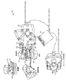
図4は、複数のマニピュレータアームを有する患者側カート22を示し、各アームは、手術器具又はツール26をマニピュレータアームの遠位端部で支持する。示される患者側カート22は、手術ツール26、又は手術部位の画像をキャプチャするために使用される立体内視鏡のような撮像装置28のいずれかを支持するために使用されることができる、4つのマニピュレータアーム100を含む。操作は、多数のロボット関節を有するロボットマニピュレータアーム100によって提供される。撮像装置28及び手術ツール26は、運動学的遠隔中心が切開部の大きさを最小にするよう切開部に維持されるように、患者の切開部を介して位置決めされ且つ操作されることができる。手術部位の画像は、手術器具又はツール26が撮像装置28の視野内に配置されるとき、手術器具又はツール26の遠位端部の画像を含むことができる。
FIG. 4 shows a patient-
手術ツール26に関して、種々の代替のロボット手術ツール又は異なる種類の器具及び様々なエンドエフェクタが、使用されることができ、マニピュレータの少なくともいくつかの器具は、外科手術中に取り外されるとともに置き換えられる。DeBakey鉗子、マイクロピンセット、ポッツはさみ、及びクリップアプライヤを含む、これらのエンドエフェクタのいくつかは、エンドエフェクタ顎部のペアを規定するように、互いに対して枢動する第1及び第2のエンドエフェクタ要素を含む。メス及び電気焼灼プローブを含む他のエンドエフェクタは、単一のエンドエフェクタ要素を有する。エンドエフェクタ顎部を有する器具に関して、顎部は大抵、ハンドルの把持部材を絞ることによって作動される。単一のエンドエフェクタ器具もまた、例えば電気焼灼プローブにエネルギを与えるために、把持部材の把持によって作動され得る。
With respect to the
器具26の細長いシャフトは、エンドエフェクタ及びシャフトの遠位端部が、低侵襲開口部を通して、大抵、腹壁等を通して手術作業部位に遠位に挿入されることを可能にする。手術作業部位はガス注入されることができ、患者内のエンドエフェクタの運動は、大抵、シャフトが低侵襲開口部を通過する位置の周りに器具26を枢動させることによって、少なくとも部分的に生み出される。換言すれば、マニピュレータ100は、エンドエフェクタの所望の動きを提供するのに役立つように、シャフトが低侵襲開口部位置を通って延びるように、器具の近位ハウジングを患者の外部で動かす。こうして、マニピュレータ100は、大抵、外科手術中、患者Pの外側で大きな動きを受ける。
The elongated shaft of the
本発明の多くの実施形態による例示的なマニピュレータアームは、図5A−12Cを参照して理解することができる。上述のように、マニピュレータアームは、一般的に、遠位器具又は手術ツールを支持し、ベースに対する器具の動きをもたらす。異なるエンドエフェクタを有する多数の異なる器具が、(典型的には、外科助手の助けを借りて)外科手術中に、各マニピュレータに順番に取り付けられるので、遠位器具ホルダは、好ましくは、取り付けられた器具又はツールの迅速な取り外し及び交換を可能にする。図4を参照して理解することができるように、マニピュレータは、患者側カートのベースに対して近位に取り付けられる。典型的には、マニピュレータアームは、ベースと遠位器具ホルダとの間に延びる複数のリンク機構及び関連する関節を含む。1つの態様では、例示的なマニピュレータは、マニピュレータアームの関節が与えられたエンドエフェクタ位置に対して異なる形態の範囲に駆動されることができるように、冗長自由度を有する複数の関節を含む。これは、本明細書に開示されたマニピュレータアームの実施形態のいずれの場合でも適用され得る。 Exemplary manipulator arms according to many embodiments of the present invention can be understood with reference to FIGS. 5A-12C. As described above, the manipulator arm generally supports a distal instrument or surgical tool and provides instrument movement relative to the base. The distal instrument holder is preferably attached because a number of different instruments with different end effectors are attached in turn to each manipulator during surgery (typically with the help of a surgical assistant). Allows for quick removal and replacement of an instrument or tool. As can be understood with reference to FIG. 4, the manipulator is attached proximally to the base of the patient side cart. Typically, the manipulator arm includes a plurality of linkages and associated joints that extend between the base and the distal instrument holder. In one aspect, an exemplary manipulator includes a plurality of joints having redundant degrees of freedom so that the joints of the manipulator arm can be driven to different forms of ranges for a given end effector position. This can be applied in any of the manipulator arm embodiments disclosed herein.
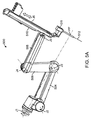
図5Aに示されるような、多くの実施形態では、例示的なマニピュレータアームは、マニピュレータアームを関節の遠位で関節軸回りに回転させるように、第1関節軸の回りに回転する近位回転関節J1を含む。いくつかの実施形態では、回転関節J1は、ベースに直接取り付けられるが、他の実施形態では、関節J1は、1又は複数の可動リンク機構又は関節に取り付けられ得る。マニピュレータの関節は、組み合わされて、マニピュレータアームの関節が、与えられたエンドエフェクタ位置について異なる形態の範囲内で駆動されることができるように、冗長自由度を有する。例えば、図5A−図5Dのマニピュレータアームは、異なる形態で操作され得る一方、器具ホルダ510内に支持された遠位部材511は特定の状態を維持し且つエンドエフェクタの与えられた位置又は速度を含み得る。遠位部材511は、典型的には、ツールシャフト512が通って延びるカニューレであり、器具ホルダ501は、典型的には、カニューレを通って患者の体内に低侵襲開口部を通って延びる前に器具が付く(スパー上を並進する煉瓦状構造として示される)キャリッジである。
In many embodiments, as shown in FIG. 5A, the exemplary manipulator arm rotates proximally about the first joint axis to rotate the manipulator arm about the joint axis distal to the joint. Includes joint J1. In some embodiments, the rotational joint J1 is attached directly to the base, but in other embodiments, the joint J1 can be attached to one or more movable linkages or joints. The manipulator joints are combined and have redundant degrees of freedom so that the manipulator arm joints can be driven within different configurations for a given end effector position. For example, the manipulator arm of FIGS. 5A-5D can be operated in different configurations, while the
図5A−図5Dのマニピュレータアーム500の個々のリンクを、図5A−図5Dに示されるようにリンクを接続する関節の回転軸に沿って説明すると、第1のリンク504は、その関節軸の回りを枢動する枢動関節J2から遠位に延び、その関節軸の回りを回転する回転関節J1に結合される。図5Aに示されるように、関節の残りの多くは、それらの関連付けられる回転軸によって識別されることができる。例えば、示されるように、第1のリンク504の遠位端部は、その枢動軸の回りを枢動する枢動関節J3で第2のリンク506の近位端部に結合され、第3のリンク508の近位端部は、その軸線の回りを枢動する枢動関節J4で第2のリンク506の遠位端部に結合される。第3のリンク508の遠位端部は、枢動関節J5で器具ホルダ510に結合される。典型的には、関節J2、J3、J4、及びJ5のそれぞれの枢動軸は、実質的に平行であり、且つ図5Dに示されるように、互いに隣接して位置決めされたときに、リンク機構は、マニピュレータアームの減少幅wを提供するとともにマニピュレータアセンブリの操縦中の患者クリアランスを向上させるように、「積み重ねられた(stacked)」ように見える。多くの実施形態では、器具ホルダはまた、低侵襲開口部を通る器具306の軸方向運動を容易にするとともに、器具が摺動自在に挿通されるカニューレに対して器具ホルダの取り付けを容易にする直動関節J6のような、追加の関節を含む。
The individual links of the
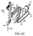
遠位部材又はそこを通ってツール512が延びるカニューレ511は、器具ホルダ510の遠位側に追加の自由度を含み得る。器具の自由度の作動は、大抵、マニピュレータのモータで駆動され、代替実施形態は、クイック取り外し可能器具ホルダ/器具インターフェイスにおいて、器具を、支持マニピュレータ構造から分離することができ、それによって、器具上に存在するものとしてここで示される1又は複数の関節が、代わりに、インターフェイス上に存在し、またその逆になる。いくつかの実施形態では、カニューレ511は、ツール先端の挿入ポイント又は枢動ポイントPPの近く又は近位の回転関節J7(図示せず)を含み、このツール先端の挿入ポイント又は枢動ポイントは、一般的に低侵襲開口部の部位に配置される。器具の遠位手首は、器具手首における1又は複数の関節の器具関節軸周りの手術ツール512のエンドエフェクタの枢動運動を可能にする。エンドエフェクタ顎部要素の間の角度は、エンドエフェクタの位置及び配向とは独立して制御され得る。
The distal member or
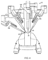
例示的なマニピュレータアセンブリの動作範囲は、図6A−6Cを参照することによって理解することができる。手術中、例示的なマニピュレータアームは、手術作業部位内の特定の患者組織にアクセスすることが必要なとき、図6Aに示されるように、ピッチフォワード形態に、又は図6Bに示されるように、ピッチバック形態に操作されることができる。典型的なマニピュレータアセンブリは、少なくとも±60度で、好ましくは約±75度で前方及び後方にピッチ動作することができ、且つまた±80度でヨー動作することができるエンドエフェクタを含む。この態様は、アセンブリでエンドエフェクタの増大した操作性を可能にするが、特に、マニピュレータアームが図6A及び6Bのように、最大のピッチフォワード又は最大のピッチバック形態にあるとき、エンドエフェクタの運動が制限され得る形態があり得る。1つの実施形態では、マニピュレータアームは、外側ピッチに関して(+/−75度)の、及び外側ヨー関節に関して(+/−300度)の動作範囲(ROM)をそれぞれ有する。幾つかの実施形態では、ROMは、(+/−90度)より大きいROMを提供するように外側ピッチに関して増大されることができ、この場合、関節の運動が制限又は不可能である空間の円錐(cone of space)が完全に消されることができるが、一般的に挿入制限に関連付けられる内球はそのままである。様々な実施形態はROMを増大又は減少させるように構成されることができ、上述のROMは説明目的で提供され、さらに、本発明は本明細書に記載されるROMに限定されるものではないことが理解される。 The operating range of an exemplary manipulator assembly can be understood by referring to FIGS. 6A-6C. During surgery, an exemplary manipulator arm may be in a pitch forward configuration, as shown in FIG. 6A, or as shown in FIG. 6B, when required to access specific patient tissue within the surgical work site. It can be operated in a pitch-back configuration. A typical manipulator assembly includes an end effector that can pitch forward and backward at least ± 60 degrees, preferably about ± 75 degrees, and can also yaw at ± 80 degrees. This aspect allows for increased operability of the end effector in the assembly, but particularly when the manipulator arm is in maximum pitch forward or maximum pitch back configuration, as in FIGS. 6A and 6B. There can be a form that can be limited. In one embodiment, the manipulator arm has an operating range (ROM) of (+/− 75 degrees) for the outer pitch and (+/− 300 degrees) for the outer yaw joint, respectively. In some embodiments, the ROM can be increased with respect to the outer pitch to provide a ROM that is greater than (+/− 90 degrees), in which case the space in which joint movement is limited or impossible. The cone of space can be completely eliminated, but the inner sphere generally associated with the insertion restriction remains intact. Various embodiments may be configured to increase or decrease the ROM, the ROM described above is provided for illustrative purposes, and the present invention is not limited to the ROM described herein. It is understood.
図6Cは、図5A−5Bの例示的なマニピュレータのツール先端の全動作範囲及び作業空間を図式的に示す。作業空間は半球として示されているが、関節J1のような、マニピュレータの1又は複数の回転関節の動作範囲及び構成に依存して球としても示され得る。示されるように、図6Cの半球は、中心の、球状の空隙並びに2つの円錐状の空隙を含む。空隙は、ツール先端の運動が、機械的な制約のために不可能又は、エンドエフェクタの運動を難しく若しくは遅くする過度に高い関節速度のために、実行不可能であり得る領域を示す。これらの理由のために、円錐状の空隙は、「沈黙円錐(cone of silence)」と称される。幾つかの実施形態では、マニピュレータアームは、円錐内のあるポイントで特異点に到達し得る。沈黙円錐内又は沈黙円錐近くでのマニピュレータの運動は損なわれ得るので、マニピュレータのリンク機構及び関節を再配置するためにマニピュレータの1又は複数のリンクを手動で動かすことなしに、マニピュレータアームを沈黙円錐から離すことは難しく、この手動で動かすことは大抵、代替動作モードを必要とし且つ手術を遅らせる。 FIG. 6C schematically illustrates the full operating range and working space of the tool tip of the exemplary manipulator of FIGS. 5A-5B. Although the workspace is shown as a hemisphere, it may also be shown as a sphere depending on the operating range and configuration of one or more rotary joints of the manipulator, such as joint J1. As shown, the hemisphere of FIG. 6C includes a central, spherical void as well as two conical voids. The voids indicate areas where tool tip movement is not possible due to mechanical constraints or may be impractical due to excessively high joint speeds that make end effector movement difficult or slow. For these reasons, conical voids are referred to as “cone of silence”. In some embodiments, the manipulator arm may reach a singular point at a point within the cone. Since the manipulator movement within or near the silence cone can be compromised, the manipulator arm can be moved to the silence cone without manually moving one or more links of the manipulator to reposition the manipulator linkages and joints. It is difficult to move away from, and this manual movement often requires an alternative mode of operation and delays surgery.
これらの円錐部分への又はこれらの円錐部分の近くの器具シャフトの運動は、典型的には、マニピュレータの遠位リンク機構の間の角度が比較的小さいときに、発生する。したがって、このような形態は、(リンク機構が互いに対してより直交位置に動かされるように)リンク機構の間の角度を増加させるためにマニピュレータの運動を異方的に強調することによって回避されることができる。例えば、図6A及び6Bに示された形態では、最遠位リンクと器具ホルダとの間の角度(角度a)が比較的小さくなるとき、マニピュレータの運動はより困難になり得る。様々な実施形態の残りの関節における関節運動の範囲に依存して、あるリンク機構の間の角度が減少するとき、マニピュレータの運動は、妨げられる場合があり、幾つかの場合には、マニピュレータアームはもはや冗長ではなくなり得る。器具シャフトがこれらの円錐状部分に近づく、又はリンク機構間の角度が比較的低いマニピュレータ形態は、マニピュレータアームの操作性及び器用さが制限されるように「不完全な状態」にあると言われる。器用さ及び運動範囲を維持するようにマニピュレータが「良い状態」にあることが望ましい。1つの態様では、本発明は、ユーザが、手術におけるエンドエフェクタの運動中でさえ、要望通りにマニピュレータを再配置するための指令を単に入力することによって、上述の円錐部分近くの器具シャフトの運動を避けることを可能にする。この態様は、マニピュレータが、何らかの理由で、「不完全な状態」になる場合に、特に有益である。 The movement of the instrument shaft to or near these conical portions typically occurs when the angle between the distal link mechanisms of the manipulator is relatively small. Thus, such a form is avoided by anisotropically enhancing the manipulator movement to increase the angle between the linkages (so that the linkages are moved to a more orthogonal position relative to each other). be able to. For example, in the configuration shown in FIGS. 6A and 6B, movement of the manipulator can be more difficult when the angle between the most distal link and the instrument holder (angle a) is relatively small. Depending on the range of articulation in the remaining joints of the various embodiments, when the angle between certain linkages decreases, manipulator movement may be impeded and in some cases the manipulator arm Can no longer be redundant. A manipulator configuration in which the instrument shaft approaches these conical sections or the angle between the linkages is relatively low is said to be "incomplete" so that manipulator arm operability and dexterity are limited. . It is desirable that the manipulator be in “good condition” to maintain dexterity and range of motion. In one aspect, the present invention provides for movement of the instrument shaft near the conical section described above by simply inputting commands for the user to reposition the manipulator as desired, even during end effector movement in surgery. Makes it possible to avoid. This aspect is particularly beneficial when the manipulator becomes “incomplete” for some reason.
上述のマニピュレータの実施形態は本発明に利用され得るが、幾つかの実施形態は、追加の関節を含むことができ、この追加の関節はまた、マニピュレータアームの器用さ及び調整を改良するために使用され得る。例えば、例示的なマニピュレータは、図5Aのマニピュレータアーム、及び、沈黙円錐を減少又は排除するために回転関節の軸周りの、それに関連付けられる、沈黙円錐を回転させるために使用されることができる、関節J1の近位の回転関節及び/又はリンク機構、を含み得る。他の実施形態では、例示的なマニピュレータはまた、器具ホルダを関節J5と実質的に直交する軸周りに枢動させる遠位枢動関節を含むことができ、それによって、沈黙円錐をさらに減少させ且つ手術ツールの運動範囲を向上させるようにツール先端をオフセットする。さらに他の実施形態では、J1のような、マニピュレータアームの近位関節は、必要に応じて沈黙円錐を動かす又は位置を変える且つマニピュレータツール先端の動作範囲を向上させるように、ベースに移動可能に取り付けられ得る。このような追加の関節の使用及び利点は、図7A−12Cを参照することによって理解されることができ、これらの図はこのような関節の例を示し、このような関節は、それぞれ、本明細書に記載される例示的なマニピュレータアームのいずれかの中で、互いに独立して使用され得る又は組み合わせて使用され得る。 Although the above-described manipulator embodiments may be utilized in the present invention, some embodiments may include additional joints that also improve the dexterity and adjustment of the manipulator arm. Can be used. For example, the exemplary manipulator can be used to rotate the manipulator arm of FIG. 5A and the associated silence cone around the axis of the rotational joint to reduce or eliminate the silence cone. It may include a rotational joint and / or a linkage mechanism proximal to joint J1. In other embodiments, the exemplary manipulator can also include a distal pivot joint that pivots the instrument holder about an axis substantially orthogonal to joint J5, thereby further reducing silence cones. The tool tip is offset to improve the range of motion of the surgical tool. In still other embodiments, the proximal joint of the manipulator arm, such as J1, is movable to the base to move or reposition the silence cone as needed and improve the operating range of the manipulator tool tip. Can be attached. The use and advantages of such additional joints can be understood by referring to FIGS. 7A-12C, which show examples of such joints, each of which is described in this book. In any of the exemplary manipulator arms described in the specification, they can be used independently of each other or used in combination.
図7A−7Bは、例示的なマニピュレータアームでの使用のための追加の冗長関節−マニピュレータアームの近位部分をベースに結合する第1の関節を示す。第1の関節は、マニピュレータアームを関節J1の関節軸周りに回転させる近位回転関節J1である。近位回転関節J1は、関節J1を近位回転関節J1’から所定の距離又は角度だけオフセットするリンク501を含む。リンク501は、図7Aに示されるように、湾曲リンク機構、又は図7Bに示されるように、直線又は傾斜リンク機構であることができる。典型的には、関節J1の関節軸は、図7Aのそれぞれに示されるように、遠隔中心RC又はツール先端の挿入ポイントと位置合わせされる。例示的な実施形態では、関節J1の関節軸は、体壁での動作を防ぐために、マニピュレータアームのそれぞれの他の回転関節がするように、遠隔中心を通過し、したがって、手術中に動かされることができる。関節J1の軸は、アームの近位部分に結合されるので、アームの後部の位置及び配向を変更するために使用されることができる。一般的に、これのような、冗長軸は、器具先端が、外科医の指令に従うことを可能にする一方同時に他のアーム又は患者の解剖学的構造との衝突を回避する。1つの態様では、近位回転関節J1は、単にフロアに対するマニピュレータの取付角度を変更するために使用される。この角度は、1)外部の患者の解剖学的構造との衝突を回避し且つ2)体内の解剖学的構造に到達するために、重要である。典型的には、近位回転関節J1に取付けられたマニピュレータの近位リンクと近位回転の軸との間の角度aは約15度である。
7A-7B show an additional redundant joint for use with an exemplary manipulator arm—a first joint that couples the proximal portion of the manipulator arm to the base. The first joint is a proximal rotary joint J1 that rotates the manipulator arm around the joint axis of the joint J1. The proximal rotational joint J1 includes a
図7Bは、近位回転関節J1とその関連付けられる関節軸と例示的なマニピュレータアームの沈黙円錐との関係を示す。近位回転関節J1の関節軸は、沈黙円錐を通過し得る又は沈黙円錐の完全に外側にあり得る。近位回転関節J1の軸周りにマニピュレータアームを回転させることによって、沈黙円錐は(関節J1軸が沈黙円錐を通過する実施形態において)減らされることができる、又は(近位回転関節軸が沈黙円錐の完全に外側に延びる実施形態において)有効に除去されることができる。リンク501の距離及び角度は、沈黙円錐に対する関節J1軸の位置を決定する。
FIG. 7B shows the relationship between the proximal rotational joint J1 and its associated joint axis and the silence cone of the exemplary manipulator arm. The joint axis of the proximal rotational joint J1 can pass through the silence cone or be completely outside the silence cone. By rotating the manipulator arm about the axis of the proximal rotational joint J1, the silence cone can be reduced (in embodiments where the joint J1 axis passes through the silence cone) or (the proximal rotational joint axis is the silence cone). Can be effectively removed). The distance and angle of the
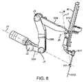
図8は、例示的なマニピュレータアームでの使用のための他の種類の冗長関節を示し、遠位回転関節J7は、器具ホルダ510をマニピュレータアーム508の遠位リンクに結合する。遠位回転関節J7は、システムが、関節軸周りに器具ホルダ510を横方向にねじることを可能にし、この関節軸は、典型的には、遠隔中心又は切開点を通過する。理想的には、回転関節はアームの遠位に位置し、したがって、特に、挿入軸の配向を動かすことによく適合している。この冗長軸の追加は、マニピュレータが、任意の1つの器具先端位置に対する多数の位置を取ることを可能にする。一般的に、これのような冗長軸は、他のアーム又は患者の解剖学的構造との衝突を回避しながら、器具先端が、外科医の指令に従うことを可能にする。遠位回転関節J7は挿入軸をヨー軸の近くに動かす能力を有するので、アームピッチバック動作範囲を増加させることができる。遠位回転関節J7の軸、J1’のヨー軸及びツール先端の挿入軸の間の関係は、図9に示される。図10A−10Cは、関節J7の連続的な運動及びどのようにそれがツール先端の挿入軸を左右に移動させるかを示す。
FIG. 8 shows another type of redundant joint for use with an exemplary manipulator arm, where the distal rotational joint J7 couples the
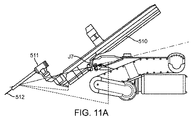
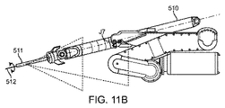
遠位回転関節J7の1つの利点は、それが患者クリアランス円錐を減少させ得ることであり、この患者クリアランス円錐は、患者と器具ホルダ又はマニピュレータアームの遠位リンク機構との間の衝突を回避するように患者を除去しなければならない切開ポイントの近位のマニピュレータアームの遠位部分の掃引容積(swept volume)である。図11Aは、遠位回転関節の角度変位が0°のままである間のマニピュレータアームの近位部分の患者クリアランス円錐を示す。図11Bは、遠位回転関節がその軸周りに90°の角度変位を有して示される間のマニピュレータアームの近位部分の減少した患者クリアランス円錐を示す。したがって、切開ポイントの近くに最少の患者クリアランスを有する手術では、本発明による関節J7の使用は、遠隔中心位置又は要望通りのエンドエフェクタ位置を維持しながら追加のクリアランスを提供し得る。 One advantage of the distal rotational joint J7 is that it can reduce the patient clearance cone, which avoids a collision between the patient and the distal linkage of the instrument holder or manipulator arm. The sweep volume of the distal portion of the manipulator arm proximal to the incision point from which the patient must be removed. FIG. 11A shows the patient clearance cone of the proximal portion of the manipulator arm while the angular displacement of the distal rotational joint remains 0 °. FIG. 11B shows a reduced patient clearance cone in the proximal portion of the manipulator arm while the distal rotational joint is shown having an angular displacement of 90 ° about its axis. Thus, in surgery with minimal patient clearance near the incision point, the use of joint J7 according to the present invention may provide additional clearance while maintaining a remote center position or desired end effector position.
図12A−12Cは、例示的なマニピュレータアームと共に使用するための他の種類の冗長関節を示し、近位関節は、軸周りにマニピュレータアームを並進又は回転させる。多くの実施形態では、この近位並進移動可能関節は、マニピュレータアームのより良い調整及び改良された操作性を提供するためにマニピュレータアームの動作範囲を変える又は回転させることによって沈黙円錐を減少又は排除するように、関節J1又はJ1’のような、マニピュレータの近位関節を経路に沿って並進移動させる。並進移動可能関節は、図12A−12Dに関節J1”で示されるように、円形経路を含み得る、又は、半円形又はアーチ形経路を含み得る。一般的に、関節は、その周りをカニューレ511を通って延びるツール512のシャフトが枢動する遠隔中心RCと交差する並進移動可能関節の軸周りにマニピュレータアームを回転させる。図示された実施形態では、J1”の軸は垂直軸であるが、様々な他の実施形態では、軸はある角度又は水平であり得る。
12A-12C illustrate another type of redundant joint for use with an exemplary manipulator arm, where the proximal joint translates or rotates the manipulator arm about an axis. In many embodiments, this proximal translatable joint reduces or eliminates silence cones by changing or rotating the manipulator arm's range of motion to provide better adjustment and improved maneuverability of the manipulator arm. As such, the proximal joint of the manipulator, such as joint J1 or J1 ′, is translated along the path. The translatable joint may include a circular path, as shown by joint J1 ″ in FIGS. 12A-12D, or may include a semi-circular or arcuate path. Generally, the joint is cannulated 511 around it. Rotate the manipulator arm about the axis of a translatable joint that intersects the remote center RC about which the shaft of the
幾つかの実施形態では、マニピュレータアーム500は、近位又は遠位回転関節、近位並進移動可能関節及び遠位リンク機構の平行四辺形構造のいずれか又は全てを含み得る。これらの特徴のいずれか又は全ての使用は、追加の冗長自由度を提供し、リンク機構の間の角度を増加させ、それによってマニピュレータの器用さ及び動作を向上させることによって、より良く「調整された」マニピュレータアセンブリを提供するように、本発明による再配置を容易にする。この例示的なマニピュレータの増加した柔軟性はまた、関節限度、特異点等を回避するために、マニピュレータリンク機構の運動学を最適化するために使用されることができる。
In some embodiments, the
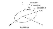
例示的な実施形態では、マニピュレータの関節運動は、システムのモータを使用してコントローラにより1又は複数の関節を駆動することによって制御され、関節は、コントローラのプロセッサによって計算された、調整された関節運動に従って駆動される。数学的には、コントローラは、ベクトル及び/又は行列を使用して関節指令の計算の少なくとも幾つかを実行することができ、そのうちのいくつかは、関節の形態又は速度に対応する要素を有し得る。プロセッサに利用可能な代替の関節形態の範囲は、関節空間として概念化され得る。例えば、関節空間は、マニピュレータが自由度を有するのと同数の次元を有し得るとともに、マニピュレータの特定の形態は、関節空間内の特定の点を表すことができ、各座標は、マニピュレータの関連付けられる関節の関節状態に対応する。 In an exemplary embodiment, the articulation of the manipulator is controlled by driving one or more joints by a controller using the system's motor, the joints being adjusted joints calculated by the controller's processor. Driven according to the movement. Mathematically, the controller can perform at least some of the joint command calculations using vectors and / or matrices, some of which have elements corresponding to joint morphology or velocity. obtain. The range of alternative joint configurations available to the processor can be conceptualized as joint space. For example, the joint space can have as many dimensions as the manipulator has degrees of freedom, and a particular form of the manipulator can represent a particular point in the joint space, each coordinate being an association of the manipulator This corresponds to the joint state of the joint to be obtained.
例示的な実施形態では、システムは、そのデカルト空間として本明細書で示される、作業空間における特徴部の指令位置及び速度が入力であるコントローラを含む。特徴部は、制御入力を使用して関節運動されることになる制御フレームとして使用できるマニピュレータ上の、又はマニピュレータから離れた任意の特徴部であり得る。本明細書に記載される多くの例で使用されるマニピュレータ上の特徴部の例は、ツール先端である。マニピュレータ上の特徴部の他の例は、ツール先端上に存在しないが、ピン又はペイントパターンのようなマニピュレータの一部である物理的な特徴部である。マニピュレータから離れた特徴部の例は、ツール先端から離れた正確な一定の距離及び角度である空き空間の基準点である。マニピュレータから離れた特徴部の別の例は、マニピュレータに対する位置が確立されることができる標的組織である。これら全ての場合において、エンドエフェクタは、制御入力を使用して関節運動されることになる仮想制御フレームに関連付けられる。しかし、以下では、「エンドエフェクタ」と「ツール先端」とは、同義的に使用される。一般的には、所望のデカルト空間のエンドエフェクタ位置を等価の関節空間位置にマッピングする閉じた形の関係はないが、一般的に、デカルト空間のエンドエフェクタと関節空間速度との間に閉じた形の関係がある。運動学的ヤコビアンは、関節空間位置要素に対するエンドエフェクタのデカルト空間位置要素の偏導関数の行列である。このように、運動学的ヤコビアンは、エンドエフェクタと関節との間の運動学的関係を捕える。換言すれば、運動学的ヤコビアンは、エンドエフェクタの関節動作の影響を捕える。運動学的ヤコビアン(J)は、以下の関係を用いて、関節空間速度(dq/dt)をデカルト空間エンドエフェクタ速度(dx/dt)にマッピングするために使用されることができる。 In an exemplary embodiment, the system includes a controller whose input is the commanded position and velocity of the feature in the workspace, shown herein as its Cartesian space. The feature can be any feature on or away from the manipulator that can be used as a control frame to be articulated using control inputs. An example of a feature on a manipulator used in many examples described herein is a tool tip. Another example of a feature on a manipulator is a physical feature that does not exist on the tool tip but is part of the manipulator such as a pin or paint pattern. An example of a feature away from the manipulator is an empty space reference point that is an exact constant distance and angle away from the tool tip. Another example of a feature remote from the manipulator is a target tissue where a position relative to the manipulator can be established. In all these cases, the end effector is associated with a virtual control frame that will be articulated using the control input. However, in the following, “end effector” and “tool tip” are used interchangeably. In general, there is no closed relationship that maps the desired Cartesian space end effector position to the equivalent joint space position, but it is generally closed between the Cartesian space end effector and the joint space velocity. There is a relationship of form. The kinematic Jacobian is a matrix of partial derivatives of the Cartesian spatial position element of the end effector relative to the joint spatial position element. Thus, the kinematic Jacobian captures the kinematic relationship between the end effector and the joint. In other words, the kinematic Jacobian captures the effects of joint motion of the end effector. The kinematic Jacobian (J) can be used to map joint space velocity (dq / dt) to Cartesian space end effector velocity (dx / dt) using the following relationship:
dx/dt=J dq/dt
したがって、入力位置と出力位置との間に閉じた形のマッピングがない場合であっても、速度のマッピングが、指令ユーザ入力からマニピュレータの運動を実現するために、ヤコビアンベースのコントローラ等で、反復的に使用されることができる。しかし、様々な実装を使用することができる。多くの実施形態は、ヤコビアンベースのコントローラを含んでいるが、いくつかの実装は、本明細書で記載した特徴のいずれかを提供するために、マニピュレータアームのヤコビアンにアクセスするように構成され得る様々なコントローラを使用し得る。
dx / dt = J dq / dt
Thus, even in the absence of a closed mapping between the input position and the output position, the velocity mapping can be repeated with a Jacobian-based controller or the like to achieve manipulator movement from the command user input. Can be used. However, various implementations can be used. Although many embodiments include a Jacobian-based controller, some implementations may be configured to access the Jacobian of the manipulator arm to provide any of the features described herein. Various controllers can be used.
1つのそのような実装は、以下の簡略化された項で記述される。指令関節位置は、ヤコビアン(J)を計算するために使用される。各時間ステップ(Δt)の間、デカルト空間速度(dx/dt)が、所望の移動(dxdes/dt)を実行するとともに所望のデカルト空間位置からの蓄積された偏差(Δx)を補正するように、計算される。このデカルト空間速度は、次に、ヤコビアンの擬似逆行列(J#)を用いて、関節空間速度(dq/dt)に変換される。得られた関節空間指令速度は、次に、関節空間指令位置(q)を生成するために積分される。これらの関係は次の通りである。 One such implementation is described in the simplified section below. The commanded joint position is used to calculate the Jacobian (J). During each time step (Δt), the Cartesian space velocity (dx / dt) performs the desired movement (dx des / dt) and corrects the accumulated deviation (Δx) from the desired Cartesian space position. To be calculated. This Cartesian space velocity is then converted to a joint space velocity (dq / dt) using the Jacobian pseudo inverse (J # ). The resulting joint space command velocity is then integrated to generate a joint space command position (q). These relationships are as follows.
dx/dt=dxdes/dt+kΔx (1)
dq/dt=J#dx/dt (2)
qi=qi−1+dq/dtΔt (3)
ヤコビアン(J)の擬似逆行列は、所望のツール先端動作(いくつかの場合では、枢動ツール動作の遠隔中心)を関節速度空間に直接マッピングする。使用されているマニピュレータが、(6までの)ツール先端の自由度より多くの有用な関節軸を有している場合、(そして、ツール動作の遠隔中心が使用されるとき、マニピュレータは、遠隔中心の位置に関連付けられた3つの自由度について追加の3つの関節軸を有するべきである)、マニピュレータは冗長であると言われる。冗長なマニピュレータのヤコビアンは、少なくとも1つの次元を有する「ゼロ空間」を含む。この文脈において、ヤコビアン(N(J))の「ゼロ空間」は、ツール先端動作を瞬時に実現しないような関節速度の空間である(そして、遠隔中心が使用されるとき、枢動点位置の移動がない);そして「ゼロ動作」は、ツール先端及び/又は遠隔中心の位置の瞬間的な移動も生成しない関節位置の組み合わせ、軌道、又は経路である。マニピュレータの所望の再配置(本明細書に記載される任意の再配置を含む)を達成するために計算されたゼロ空間速度をマニピュレータの制御システムに組み込む又は注入することは、上記の式(2)を以下のように変形する:
dq/dt=dqprep/dt+dqnull/dt (4)
dqprep/dt=J#dx/dt (5)
dqnull/dt=(1−J#J)z=VnVn Tz=Vnα (6)
式(4)による関節速度は、2つの成分を有し:第1は、ゼロ直交空間成分、所望のツール先端動作を生成する「純粋な(purest)」関節速度(最短ベクトルの長さ)(そして、遠隔中心が使用されるときに、所望の遠隔中心動作)であり、第2の成分は、ゼロ空間成分である。式(2)及び式(5)は、ゼロ空間成分なしで、同じ式が得られることを示している。式(6)は、左辺のゼロ空間成分についての従来の形式で始まり、最も右寄りの右辺で、例示的なシステムで用いられる形式を示し、ここで、Vnは、ゼロ空間についての直交基底ベクトルのセットであり、αは、それら基底ベクトルをブレンドする(blending)ための係数である。いくつかの実施形態では、αは、要望通りにゼロ空間内の動作を形成又は制御するために、例えばノブ又は他の制御手段の使用によって等、制御パラメータ、変数又は設定によって決定される。
dx / dt = dx des / dt + kΔx (1)
dq / dt = J # dx / dt (2)
q i = q i−1 + dq / dtΔt (3)
Jacobian (J) pseudo-inverse maps the desired tool tip motion (in some cases the remote center of the pivot tool motion) directly into the joint velocity space. If the manipulator being used has more useful joint axes than tool tip degrees of freedom (up to 6) (and when a remote center of tool motion is used, the manipulator ), The manipulator is said to be redundant. The redundant manipulator Jacobian includes a “zero space” having at least one dimension. In this context, the Jacobian (N (J)) “zero space” is the space of joint velocity that does not instantaneously realize tool tip motion (and when the remote center is used, the pivot point position "Zero motion" is a joint position combination, trajectory, or path that does not produce an instantaneous movement of the tool tip and / or remote center position. Incorporating or injecting the calculated zero space velocity into the manipulator control system to achieve the desired relocation of the manipulator (including any of the relocations described herein) ) Is transformed as follows:
dq / dt = dq prep / dt + dq null / dt (4)
dq prep / dt = J # dx / dt (5)
dq null / dt = (1- J # J) z = V n V n T z = V n α (6)
The joint velocity according to equation (4) has two components: the first is the zero orthogonal spatial component, the “purest” joint velocity (the length of the shortest vector) that produces the desired tool tip motion ( And when the remote center is used, the desired remote center operation), and the second component is the zero space component. Equations (2) and (5) show that the same equation can be obtained without a zero space component. Equation (6) starts with the conventional form for the left-side zero-space component and shows the form used in the exemplary system, with the rightmost right-hand side, where V n is the orthogonal basis vector for zero-space. Α is a coefficient for blending these basis vectors. In some embodiments, α is determined by a control parameter, variable, or setting, such as by use of a knob or other control means, such as by using a knob or other control means, to form or control movement in zero space as desired.
図13A−13Bは、ヤコビアンのゼロ空間と例示的なマニピュレータアームのヤコビアンのゼロ直交空間との間の関係を図式的に示す。図13Aは、水平軸に沿ったゼロ空間と、垂直軸に沿ったゼロ直交空間とを示す二次元の概略図を示し、2つの軸は、互いに直交する。斜めのベクトルは、ゼロ空間における速度ベクトルとゼロ直交空間における速度ベクトルの和を表し、この和は、上記の式(4)を表す。 13A-13B schematically illustrate the relationship between the Jacobian zero space and the Jacobian zero orthogonal space of an exemplary manipulator arm. FIG. 13A shows a two-dimensional schematic showing a zero space along the horizontal axis and a zero orthogonal space along the vertical axis, the two axes being orthogonal to each other. The diagonal vector represents the sum of the velocity vector in the zero space and the velocity vector in the zero orthogonal space, and this sum represents the above equation (4).
図13Bは、「ゼロ動作多様体」として示される、4次元関節空間内のゼロ空間とゼロ動作多様体との間の関係を図式的に示す。各矢印(q1、q2、q3、及びq4)は、主要な関節軸を表す。閉曲線は、同じエンドエフェクタ位置を瞬時に実現する関節空間位置のセットであるゼロ動作多様体を表す。この曲線上の与えられた点Aに関して、ゼロ空間は、エンドエフェクタの運動を瞬時に生じさせない関節速度の空間であるので、ゼロ空間は、点Aでのゼロ動作多様体の接線に対して平行である。 FIG. 13B schematically illustrates the relationship between the zero space and the zero motion manifold in the four-dimensional joint space, denoted as “zero motion manifold”. Each arrow (q1, q2, q3, and q4) represents a major joint axis. The closed curve represents a zero motion manifold that is a set of joint space positions that instantly achieve the same end effector position. For a given point A on this curve, the null space is parallel to the tangent of the zero motion manifold at point A because the null space is a joint velocity space that does not cause end effector motion instantaneously. It is.
第1のアプローチ、上記の関節空間重み付き疑似逆行列アプローチでは、システムは、ヤコビ行列の重み付き疑似逆行列を計算する。例えば、ヤコビアンの定義に沿った連鎖律を使用して、結果が以下の式にしたがって得られることができ、この中でWは関節速度に重み付けするために使用される重み付き行列であり、()#は疑似逆行列解である:
dx/dt=J*dq/dt (7)
dx/dt=J*W*W(−1)*dq/dt (8)
W(−1)*dq/dt=(J*W)#*dx/dt (9)
dq/dt=W*(J*W)#*dx/dt (10)
他のアプローチ、カート空間重み付き疑似逆行列アプローチでは、以下の式が使用され得る:
dx/dt=J*dq/dt
W*dx/dt=W*J*dq/dt
dq/dt=(W*J)#(W*dx/dt)
例:
W=対角([110111])に設定する。これは、第3のカート空間速度要素、すなわちZに沿った並進移動を、dq/dtに0の影響を与えさせ、したがって、結果として得られる関節速度がエンドエフェクタZに沿って0の並進移動を生み出す。
In the first approach, the joint space weighted pseudo inverse matrix approach described above, the system computes a weighted pseudo inverse matrix of the Jacobian matrix. For example, using a chain rule along the Jacobian definition, the result can be obtained according to the following equation, where W is a weighted matrix used to weight the joint velocity: ) # Is a pseudo inverse matrix solution:
dx / dt = J * dq / dt (7)
dx / dt = J * W * W (-1) * dq / dt (8)
W (−1) * dq / dt = (J * W) # * dx / dt (9)
dq / dt = W * (J * W) # * dx / dt (10)
In another approach, the cart space weighted pseudo-inverse approach, the following equation can be used:
dx / dt = J * dq / dt
W * dx / dt = W * J * dq / dt
dq / dt = (W * J) # (W * dx / dt)
Example:
Set W = diagonal ([110111]). This causes the translation along the third cart space velocity element, Z, to have a zero impact on dq / dt, and thus the resulting joint velocity is zero translation along the end effector Z. Produce.
重み付き関節速度は、上述の式の使用によって得られることができるが、このアプローチに関連付けられる幾つかの欠点があり得る。例えば、マニピュレータ運動に関連付けられる様々なタスクが、様々な他のアルゴリズムで使用されるゼロ空間基底ベクトルのような、特異値分解計算の重み付きでない関節速度を使用する場合、このアプローチは、これらの様々な他のタスクに関する追加の特異値分解計算を必要とし得る。 Although weighted joint velocities can be obtained through the use of the above equation, there can be several drawbacks associated with this approach. For example, if various tasks associated with manipulator motion use unweighted joint velocities for singular value decomposition calculations, such as the zero-space basis vectors used in various other algorithms, this approach Additional singular value decomposition calculations for various other tasks may be required.
上述の、第2のアプローチでは、計算の必要な数を最小にするために、システムは、重み付きでない関節速度に基づいて関節速度に重みを適用するように構成されることができ、それによって、各カーネルサイクルに関して1つの特異値分解のみを必要とする。したがって、様々な他のタスク又は運動は、重み付きでない関節速度を利用することができる一方、重み付けが指令運動中に関節の第1のセットの所望の関節状態又は運動を提供するように関節速度に適用される。このアプローチでは、上述の式(2)又は(5)から得られ得るように、ヤコビアンの疑似逆行列からのdq/dtが、勾配を決定するために関節速度空間の重みを示す異方性表面に適用される。その後、疑似逆行列解と疑似逆行列解における表面の勾配との間の差が、重み付き補正値になり、この重み付き補正値は、重み付き関節速度を決定するためにゼロ空間の上に射影される。 In the second approach described above, in order to minimize the required number of calculations, the system can be configured to apply weights to joint speeds based on unweighted joint speeds, thereby Only one singular value decomposition is required for each kernel cycle. Thus, various other tasks or movements can take advantage of unweighted joint speeds while joint speeds such that weighting provides the desired joint state or movement of the first set of joints during the commanded movement. Applies to In this approach, an anisotropic surface where dq / dt from the Jacobian pseudoinverse indicates the weight of the joint velocity space to determine the slope, as can be derived from equations (2) or (5) above. Applies to After that, the difference between the pseudo-inverse solution and the surface gradient in the pseudo-inverse solution becomes the weighted correction value, which is over the zero space to determine the weighted joint velocity. Projected.
図14は、第2のアプローチの例を図式的に示す。重み付けWは、関節空間内の異方性放物面として描かれる。dq/dtで標識されるベクトルは、ツール先端及び/又は遠隔中心の指令運動に応じて計算されるオリジナルの疑似逆行列解である。関節速度の重みを示す異方性放物面の勾配gは、dw/dtベクトルと勾配との間の差Δを決定するために(g’で示される)オリジナルに動かされ、この勾配は、その後、dqnull/dtを決定するために関節のゼロ空間の上に射影され、このdqnull/dtは、重み付き関節速度を決定するために使用される。理想的な関節速度ベクトルは、常に達成可能とは限らないので、結果として得られるベクトル、dqnull/dt+dqprep/dtは重み付けによって定められる関節運動に近づく。 FIG. 14 schematically shows an example of the second approach. The weight W is drawn as an anisotropic paraboloid in the joint space. The vector labeled dq / dt is the original pseudo inverse matrix solution calculated in response to the tool tip and / or remote center command motion. An anisotropic paraboloid gradient g, indicating the joint velocity weight, is moved to the original (denoted g ′) to determine the difference Δ between the dw / dt vector and the gradient, It is then projected onto the joint zero space to determine dq null / dt, which dq null / dt is used to determine the weighted joint velocity. Since the ideal joint velocity vector is not always achievable, the resulting vector, dq null / dt + dq prep / dt, approaches the joint motion defined by the weighting.
このアプローチは、以下の式の使用によって達成され、そこではCは放物面によって定められるコスト関数であり、gは勾配であり、Vnはゼロ空間基底ベクトルを示す。
This approach is achieved by using the following equation, where C is a cost function defined by a paraboloid, g is a gradient, and V n represents a zero-space basis vector.

典型的には、上述の勾配標記では、括弧内の式は、勾配が式に対して取られることを示すために、下げられなければならない。そのため、g(x)y=(dy/dx)T。
(12)とオリジナルのdqprep/dtとの間の差である、補正値は:
Δ=WT*W*dqprep/dt−dqprep/dt=(WT*W−1)*dqprep/dt (13)
Δをゼロ空間上に、規定ベクトルVnを用いて射影することは次に式をもたらす:
dqnull/dt=Vn*Vn T*Δ=Vn*Vn T*(WT*W−1)*dqprep/dt (14)
dqprep/dtは疑似逆行列解であるので、ゼロ空間へのその射影はゼロであり、したがって、
Vn*Vn T*dqprep/dt=0 (15)
dqnull/dt=Vn*Vn T*WT*dqprep/dt (16)
上述の式の使用によって、所望の重み付き関節速度が、対角に沿ってゼロを持つ対角行列であることができ、重み付きでない特異分解値は、上述のアルゴリズムのいずれかでの使用を含む、様々なタスクの多数のユーザによって共有されることができる。関節に対して重みを設定することによって、式(16)は、かなり最小の計算で重み付き関節速度にしたがって関節の速度プロファイルを調整するためにゼロ空間ベクトルを生成するように使用されることができる。
Typically, in the gradient notation above, the expression in parentheses must be lowered to indicate that a gradient is taken for the expression. Therefore, g (x) y = (dy / dx) T.
The correction value, which is the difference between (12) and the original dq prep / dt, is:
Δ = W T * W * dq prep / dt−dq prep / dt = (W T * W−1) * dq prep / dt (13)
Projecting Δ onto the zero space with the prescribed vector V n yields the following equation:
dq null / dt = V n * V n T * Δ = V n * V n T * (W T * W−1) * dq prep / dt (14)
Since dq prep / dt is a pseudo-inverse solution, its projection to zero space is zero, so
V n * V n T * dq prep / dt = 0 (15)
dq null / dt = V n * V n T * W T * dq prep / dt (16)
Through the use of the above equation, the desired weighted joint velocity can be a diagonal matrix with zero along the diagonal, and the unweighted singular decomposition values can be used in any of the above algorithms. It can be shared by multiple users of various tasks, including. By setting weights for the joints, equation (16) can be used to generate a zero-space vector to adjust the joint velocity profile according to the weighted joint speed with a fairly minimal calculation. it can.
代替的には、幾つかの態様では、ポテンシャル関数勾配を組み込み且つデカルト空間エンドエフェクタ速度に適用される拡張ヤコビアンが使用され得る。ヤコビアンの拡張は、要望通りに関節速度を計算する。ヤコビアンを使用して関節運動を計算することを述べることにおいて、このような計算は拡張ヤコビアンアプローチを含み得ることが理解される。拡張ヤコビアンアプローチにしたがって、以下の式が使用されるが、列ベクトルが使用され得ることが理解される:
dx/dt=J*dq/dt
y=h(q)
dy/dt=∂h/∂q*dq/dt
[dx/dtT dy/dtT]T=[JT ∂h/∂qT]T*dq/dt
d(x;y)/dt=[J;h’]*dq/dt
dq/dt=[J;h’]#d(x;y)/dt
第1の例では:dy/dt=0、∂h/∂q=[0 0 1 −2 0 0 0]に設定し、これは、関節3の速度を関節4の速度の2倍と等しくさせることを試みる。
Alternatively, in some aspects, an extended Jacobian that incorporates a potential function gradient and is applied to the Cartesian space end effector velocity may be used. Jacobian expansion calculates joint velocity as desired. In describing the calculation of joint motion using the Jacobian, it is understood that such a calculation can include an extended Jacobian approach. According to the extended Jacobian approach, the following formula is used, but it is understood that a column vector can be used:
dx / dt = J * dq / dt
y = h (q)
dy / dt = ∂h / ∂q * dq / dt
[Dx / dt T dy / dt T ] T = [J T ∂h / ∂q T ] T * dq / dt
d (x; y) / dt = [J; h ′] * dq / dt
dq / dt = [J; h ′] # d (x; y) / dt
In the first example: set dy / dt = 0, ∂h / ∂q = [0 0 1 -2 0 0 0], which makes the speed of joint 3 equal to twice the speed of joint 4 Try that.
第2の例では:dy/dt=0、∂h/∂q=[0 0 1 0 0 0 0]に設定し、これは、関節3の速度を0と等しくさせることを試みる。 In the second example, set: dy / dt = 0, ∂h / ∂q = [0 0 1 0 0 0 0], which attempts to make the velocity of joint 3 equal to zero.
図15は、上述の式に関連して、患者側カート関節状態を制御するための一般的なアルゴリズムを実装する必要がある必須のブロックの簡略図を示す。図15の方法によれば、システムは:マニピュレータアームの順運動学を計算し;次に、式(1)を用いてdx/dtを計算し、式(5)を用いてdqprep/dtを計算し、次に、式(6)を用いて、dqprep/dt及びヤコビアンに依存し得るzからdqnull/dtを計算する。計算されたdqprep/dt及びdqnull/dtから、システムは、式(4)及び式(3)使用してdq/dt及びqをそれぞれ計算し、それによって、所望のエンドエフェクタの状態(及び/又は遠隔中心の位置)を維持しながら、コントローラがマニピュレータの所望の再配置を生じさせることができる計算された運動を提供する。 FIG. 15 shows a simplified diagram of the required blocks that need to implement a general algorithm for controlling patient-side cart joint conditions in connection with the above equations. According to the method of FIG. 15, the system: calculates the forward kinematics of the manipulator arm; then calculates dx / dt using equation (1) and dq prep / dt using equation (5). And then using equation (6), calculate dq null / dt from dq prep / dt and z that may depend on the Jacobian. From the calculated dq prep / dt and dq null / dt, the system uses equations (4) and (3) to calculate dq / dt and q, respectively, thereby determining the desired end effector state (and The controller provides a calculated motion that can cause the desired repositioning of the manipulator while maintaining a remote center position).
図16−17は、本発明による例示的な方法のフローチャートを示す。例示的な方法では、図16に示されるように、システムは、所望のエンドエフェクタ運動にしたがってエンドエフェクタを動かすようにユーザによる操作指令入力に応じて関節の第1のセットの所望の運動に対応する重み付き行列を使用して重み付き関節速度を決定することを含む。システムは次に、所望のエンドエフェクタ運動を生じさせるとともに関節の第1のセットの所望の運動を提供するように、重み付き関節速度にしたがって関節を駆動する。図17に示されるように、方法はさらに、疑似逆行列解を使用して指令エンドエフェクタ運動を達成する関節速度を決定することを含み得る。重み付き関節速度は、上述のように、疑似逆行列解の勾配(例えば、ポテンシャル関数勾配)を使用して及び関節空間内で重み付き行列を使用して関節速度を調整することによって計算されることができる。システムは、所望のエンドエフェクタ運動を生じさせるとともに関節の第1のセットの所望の運動を提供するように、重み付き関節速度にしたがって関節を駆動する。任意選択で、システムは、指令再配置又は衝突回避のような、1又は複数の補助タスクに関連付けられる関節速度を計算するために重み付き表面での疑似逆行列解を使用し得るので、関節は、指令エンドエフェクタ運動の間、関節の第1のセットの所望の運動をなお提供しながら、補助タスクを生じさせるために駆動されることができる。 Figures 16-17 show a flowchart of an exemplary method according to the present invention. In the exemplary method, as shown in FIG. 16, the system responds to a desired motion of the first set of joints in response to an operational command input by a user to move the end effector according to the desired end effector motion. Determining weighted joint velocities using a weighted matrix. The system then drives the joint according to the weighted joint speed to produce the desired end effector movement and to provide the desired movement of the first set of joints. As shown in FIG. 17, the method may further include determining a joint velocity to achieve commanded end effector motion using a pseudo inverse matrix solution. The weighted joint velocity is calculated as described above by adjusting the joint velocity using a pseudo inverse matrix solution gradient (eg, potential function gradient) and using a weighted matrix in the joint space. be able to. The system drives the joint according to the weighted joint speed to produce the desired end effector movement and to provide the desired movement of the first set of joints. Optionally, the system may use a pseudo inverse matrix solution on the weighted surface to calculate the joint velocity associated with one or more auxiliary tasks, such as command relocation or collision avoidance, so that the joint During the command end effector movement, it can be driven to create an auxiliary task while still providing the desired movement of the first set of joints.
例示的な実施例は、理解を明確にするために及び例としてある程度詳細に記載されているが、種々の適合、修正、及び変更が、当業者には明らかであろう。従って、本発明の範囲は、添付の特許請求の範囲によってのみ限定される。 While illustrative embodiments have been described in some detail for purposes of clarity of understanding and by way of example, various adaptations, modifications and changes will be apparent to those skilled in the art. Accordingly, the scope of the invention is limited only by the appended claims.
Claims (35)
所望のエンドエフェクタ運動で前記エンドエフェクタを動かすように操作指令を受信するステップ;
前記複数の関節の関節空間内で重み付けを使用して調整される関節速度を計算することによって、前記複数の関節の重み付き関節速度を決定するステップであって、前記重み付けは、前記複数の関節の関節の第1のセットの所望の運動に対応する、ステップ;並びに
前記所望のエンドエフェクタ運動及び前記関節の第1のセットの所望の運動を生じさせるように前記重み付き関節速度にしたがって前記複数の関節を駆動するステップ;を含む、
ロボット方法。 Providing a manipulator arm comprising a movable distal surgical end effector, a proximal portion coupled to a base, and a plurality of joints between the distal portion and the base, the plurality of joints Has sufficient degrees of freedom to allow a range of different joint states for a given end effector state;
Receiving an operation command to move the end effector in a desired end effector motion;
Determining weighted joint velocities of the plurality of joints by calculating joint velocities adjusted using weights within a joint space of the plurality of joints, wherein the weighting includes the plurality of joints Corresponding to the desired movement of the first set of joints; and the plurality according to the weighted joint speed to produce the desired end effector movement and the desired movement of the first set of joints. Driving the joint of the
Robot way.
請求項1に記載のロボット方法。 The first set of joints includes one or more joints of the plurality of joints;
The robot method according to claim 1.
請求項1に記載のロボット方法。 The desired motion includes: joint state, joint state combination, relative joint state, range of joint state, joint state profile, kinetic energy, or any combination thereof,
The robot method according to claim 1.
請求項1に記載のロボット方法。 The step of determining the weighted joint velocity applies a Jacobian weighted pseudo-inverse to the Cartesian space end effector velocity;
The robot method according to claim 1.
請求項1に記載のロボット方法。 The weighting includes a weighted matrix of the joint space;
The robot method according to claim 1.
請求項1に記載のロボット方法。 Determining an end effector displacement movement of the plurality of joints to produce the desired end effector movement by calculating a joint velocity for the plurality of joints to achieve the desired end effector movement. The calculated joint velocity is used to determine the weighted joint velocity;
The robot method according to claim 1.
請求項6に記載のロボット方法。 Determining the end effector motion includes calculating a Jacobian pseudo inverse matrix solution, and determining the weighted joint velocity includes the pseudo inverse matrix solution and a potential function gradient of the pseudo inverse matrix solution; Including calculating the difference between
The robot method according to claim 6.
請求項7に記載のロボット方法。 The weighting includes a quadric surface in the joint space,
The robot method according to claim 7.
請求項8に記載のロボット方法。 The weighting includes a paraboloid in the joint space;
The robot method according to claim 8.
請求項7に記載のロボット方法。 The difference is projected onto the Jacobian zero space to determine a zero space vector of the joint velocity;
The robot method according to claim 7.
前記エンドエフェクタの所望の状態を維持しながら計算された前記補助運動にしたがって前記関節を駆動するステップ、をさらに含む、
請求項7に記載のロボット方法。 Determining one or more auxiliary movements of the plurality of joints using the calculated joint speed; and driving the joints according to the calculated auxiliary movements while maintaining a desired state of the end effector; Further comprising:
The robot method according to claim 7.
請求項11に記載のロボット方法。 The one or more auxiliary movements include a command repositioning movement, a collision avoidance movement, an auxiliary task, or any combination thereof.
The robot method according to claim 11.
請求項11に記載のロボット方法。 The one or more auxiliary movements include a desired movement of a second set of joints of the plurality of joints;
The robot method according to claim 11.
請求項1に記載のロボット方法。 A distal portion of the manipulator arm is coupled to an instrument holder that releasably supports a surgical instrument having an elongated shaft extending distally to the end effector, the instrument shaft pivoting about a remote center during surgery. ,
The robot method according to claim 1.
請求項1に記載のロボット方法。 The first set of joints includes a subset of joints, the first joint from the first set of joints couples the proximal portion to the base, and the first joint is a rotational joint. A pivot joint that supports the distal portion of the manipulator arm so that articulation of the pivot pivots the distal portion of the manipulator arm about the pivot axis of the rotary joint, the pivot axis comprising: Extending from the rotational joint through the remote center such that the insertion axis of the manipulator arm moves along a distally tapered cone oriented toward the remote center;
The robot method according to claim 1.
前記エンドエフェクタを所望のエンドエフェクタ運動で動かすように操作指令を受信するための入力部;並びに
前記入力装置を前記マニピュレータアームに結合するプロセッサであって:
前記複数の関節の関節空間内で重み付けを用いて関節速度を計算することにより、前記操作指令を受信することに応じて、前記関節のエンドエフェクタ変位運動を計算することによって、重み付き関節速度を計算し、前記重み付けは前記複数の関節の関節の第1のセットの所望の運動に対応し、
前記所望のエンドエフェクタ運動及び前記関節の第1のセットの所望の運動を生じさせるように計算された前記重み付き関節速度で前記マニピュレータアームを駆動するように、前記エンドエフェクタ変位運動に応じて前記マニピュレータアームに指令を送信する、
プロセッサ、を有する、
ロボットシステム。 A manipulator arm configured to robotically move a distal end effector relative to a proximal base, wherein the manipulator arm includes a plurality of manipulator arms between the distal portion and a proximal portion coupled to the base. A manipulator arm that provides a sufficient degree of freedom to allow a range of joint states relative to an end effector state;
An input for receiving an operation command to move the end effector in a desired end effector motion; and a processor coupling the input device to the manipulator arm:
By calculating a joint velocity using weighting in the joint space of the plurality of joints, and calculating an end effector displacement motion of the joint in response to receiving the operation command, a weighted joint velocity is obtained. Calculating and the weighting corresponds to a desired motion of a first set of joints of the plurality of joints;
In response to the end effector displacement movement to drive the manipulator arm at the weighted joint speed calculated to produce the desired end effector movement and the desired movement of the first set of joints. Send commands to the manipulator arm,
Having a processor,
Robot system.
請求項16に記載のロボットシステム。 The first set of joints includes one or more joints of the plurality of joints;
The robot system according to claim 16.
請求項16に記載のロボットシステム。 The desired motion includes: joint state, joint state combination, relative joint state, joint state range, joint state profile, or any combination thereof,
The robot system according to claim 16.
請求項16に記載のロボットシステム。 The processor is configured such that determining the weighted joint velocity applies a Jacobian weighted pseudo-inverse to a Cartesian space end effector velocity.
The robot system according to claim 16.
請求項19に記載のロボットシステム。 The weighting includes a weighted matrix of the joint space;
The robot system according to claim 19.
前記所望のエンドエフェクタ運動を達成するヤコビ行列のゼロ直交空間内で関節速度を計算することによって、前記操作指令に応じて前記関節のエンドエフェクタ変位運動を計算するように、構成される、
請求項16に記載のロボットシステム。 The processor is:
Configured to calculate an end effector displacement motion of the joint in response to the operational command by calculating a joint velocity in a zero orthogonal space of a Jacobian matrix that achieves the desired end effector motion.
The robot system according to claim 16.
請求項21に記載のロボットシステム。 The processor includes determining the end effector motion includes calculating a pseudo inverse matrix solution of the Jacobian, and determining the weighted joint velocity includes the pseudo inverse matrix solution and the pseudo inverse matrix solution. Comprising calculating a difference between the potential function gradient of
The robot system according to claim 21.
請求項22に記載のロボットシステム。 The weighting includes a quadric surface in the joint space,
The robot system according to claim 22.
請求項22に記載のロボットシステム。 The difference is projected onto the zero space of the Jacobian to determine a zero space vector of the joint velocity;
The robot system according to claim 22.
前記エンドエフェクタの所望の状態を維持しながら計算された前記補助運動にしたがって前記関節を駆動すること、をさらに含む、
請求項16に記載のロボットシステム。 Determining one or more auxiliary movements of the plurality of joints using the calculated joint speed; and driving the joints according to the calculated auxiliary movements while maintaining a desired state of the end effector Further including,
The robot system according to claim 16.
請求項16に記載のロボットシステム。 The one or more auxiliary movements include a command repositioning movement, a collision avoidance movement, an auxiliary task, or any combination thereof.
The robot system according to claim 16.
請求項25に記載のロボットシステム。 The one or more auxiliary movements include a desired movement of a second set of joints of the plurality of joints;
The robot system according to claim 25.
請求項16に記載のロボットシステム。 The distal portion of the manipulator arm is configured to releasably support a surgical instrument having an elongated shaft extending distally to the end effector such that the instrument shaft pivots about a remote center during surgery. Combined with the instrument holder,
The robot system according to claim 16.
請求項16に記載のロボットシステム。 The plurality of joints includes a remote spherical central joint disposed distally of and proximal to the proximal portion, wherein the remote spherical central joint includes articulation of the remote spherical central joint; Mechanically constrained to pivot the distal portion of the manipulator arm about first, second, and third remote central axes, the first, second, and third remote A central axis intersects the remote center,
The robot system according to claim 16.
請求項16に記載のロボットシステム。 The proximal portion is mechanically constrained relative to the base such that when the proximal portion moves, the distal portion of the manipulator arm pivots about the remote center;
The robot system according to claim 16.
請求項16に記載のロボットシステム。 The first set of joints includes a subset of joints, the first joint from the first set of joints couples the proximal portion to the base, and the first joint is a rotational joint. A pivot joint that supports the distal portion of the manipulator arm so that articulation of the pivot pivots the distal portion of the manipulator arm about the pivot axis of the rotary joint, the pivot axis comprising: Extending from the rotary joint through the remote center such that the insertion axis of the manipulator arm moves along a distally tapered cone oriented toward the remote center;
The robot system according to claim 16.
請求項1に記載のロボット方法。 Determining the weighted joint velocity applies an expanded Jacobian to a Cartesian space end effector velocity, and the Jacobian expansion weights the joint velocity calculated as desired.
The robot method according to claim 1.
請求項1に記載のロボット方法。 The weighting includes a weighted matrix in a Cartesian space of the end effector.
The robot method according to claim 1.
請求項16に記載のロボットシステム。 The processor is configured such that determining the weighted joint velocity applies an expanded Jacobian to a Cartesian space end effector velocity, and the Jacobian expansion weights the joint velocity calculated as desired. Configured as
The robot system according to claim 16.
請求項19に記載のロボットシステム。 The weighting includes a weighted matrix in a Cartesian space of the end effector.
The robot system according to claim 19.
Applications Claiming Priority (3)
| Application Number | Priority Date | Filing Date | Title |
|---|---|---|---|
| US201361800924P | 2013-03-15 | 2013-03-15 | |
| US61/800,924 | 2013-03-15 | ||
| PCT/US2014/031105 WO2014146120A1 (en) | 2013-03-15 | 2014-03-18 | Systems and methods for using the null space to emphasize anipulator joint motion anisotropically |
Related Child Applications (1)
| Application Number | Title | Priority Date | Filing Date |
|---|---|---|---|
| JP2019020872A Division JP2019111352A (en) | 2013-03-15 | 2019-02-07 | Systems and methods for using null space to emphasize manipulator joint motion anisotropically |
Publications (2)
| Publication Number | Publication Date |
|---|---|
| JP2016512733A true JP2016512733A (en) | 2016-05-09 |
| JP2016512733A5 JP2016512733A5 (en) | 2017-04-20 |
Family
ID=50513517
Family Applications (2)
| Application Number | Title | Priority Date | Filing Date |
|---|---|---|---|
| JP2016502607A Pending JP2016512733A (en) | 2013-03-15 | 2014-03-18 | System and method using zero space to anisotropically enhance manipulator joint motion |
| JP2019020872A Pending JP2019111352A (en) | 2013-03-15 | 2019-02-07 | Systems and methods for using null space to emphasize manipulator joint motion anisotropically |
Family Applications After (1)
| Application Number | Title | Priority Date | Filing Date |
|---|---|---|---|
| JP2019020872A Pending JP2019111352A (en) | 2013-03-15 | 2019-02-07 | Systems and methods for using null space to emphasize manipulator joint motion anisotropically |
Country Status (6)
| Country | Link |
|---|---|
| US (2) | US9468501B2 (en) |
| EP (1) | EP2969404B1 (en) |
| JP (2) | JP2016512733A (en) |
| KR (1) | KR102214811B1 (en) |
| CN (1) | CN105050529B (en) |
| WO (1) | WO2014146120A1 (en) |
Cited By (3)
| Publication number | Priority date | Publication date | Assignee | Title |
|---|---|---|---|---|
| WO2020161910A1 (en) * | 2019-02-08 | 2020-08-13 | 日本電気株式会社 | Control device, control method, and recording medium |
| WO2021112229A1 (en) * | 2019-12-05 | 2021-06-10 | 川崎重工業株式会社 | Surgery support robot and control method thereof |
| WO2022172590A1 (en) * | 2021-02-12 | 2022-08-18 | 川崎重工業株式会社 | Surgery assistance system, patient-side device, and method for controlling surgery assistance system |
Families Citing this family (36)
| Publication number | Priority date | Publication date | Assignee | Title |
|---|---|---|---|---|
| US9119655B2 (en) | 2012-08-03 | 2015-09-01 | Stryker Corporation | Surgical manipulator capable of controlling a surgical instrument in multiple modes |
| EP3620121B1 (en) | 2012-08-03 | 2024-01-31 | Stryker Corporation | Systems for robotic surgery |
| US9226796B2 (en) | 2012-08-03 | 2016-01-05 | Stryker Corporation | Method for detecting a disturbance as an energy applicator of a surgical instrument traverses a cutting path |
| KR102109594B1 (en) | 2012-08-15 | 2020-05-12 | 인튜어티브 서지컬 오퍼레이션즈 인코포레이티드 | Systems and methods for cancellation of joint motion using the null-space |
| EP2969404B1 (en) * | 2013-03-15 | 2021-08-11 | Intuitive Surgical Operations, Inc. | Systems for using the null space to emphasize anipulator joint motion anisotropically |
| KR102397402B1 (en) | 2014-03-17 | 2022-05-13 | 인튜어티브 서지컬 오퍼레이션즈 인코포레이티드 | System and method for maintaining a tool pose |
| US10327855B2 (en) * | 2014-09-17 | 2019-06-25 | Intuitive Surgical Operations, Inc. | Systems and methods for utilizing augmented Jacobian to control manipulator joint movement |
| US10617479B2 (en) | 2014-10-27 | 2020-04-14 | Intuitive Surgical Operations, Inc. | System and method for integrated surgical table motion |
| KR20240050443A (en) | 2014-10-27 | 2024-04-18 | 인튜어티브 서지컬 오퍼레이션즈 인코포레이티드 | Medical device with active brake release control |
| CN107072725B (en) | 2014-10-27 | 2019-10-01 | 直观外科手术操作公司 | System and method for integrated surgical platform |
| KR102617042B1 (en) | 2014-10-27 | 2023-12-27 | 인튜어티브 서지컬 오퍼레이션즈 인코포레이티드 | System and method for registering to a surgical table |
| CN107072746B (en) | 2014-10-27 | 2020-06-09 | 直观外科手术操作公司 | System and method for integrating surgical table icons |
| KR102574095B1 (en) | 2014-10-27 | 2023-09-06 | 인튜어티브 서지컬 오퍼레이션즈 인코포레이티드 | System and method for instrument disturbance compensation |
| KR102479287B1 (en) | 2014-10-27 | 2022-12-20 | 인튜어티브 서지컬 오퍼레이션즈 인코포레이티드 | System and method for monitoring control points during reactive motion |
| DE102014118001A1 (en) * | 2014-12-05 | 2016-06-09 | Broetje-Automation Gmbh | Method for simulating the motion of a manipulator |
| WO2017146890A1 (en) | 2016-02-26 | 2017-08-31 | Intuitive Surgical Operations, Inc. | System and method for collision avoidance using virtual boundaries |
| JP2019509103A (en) * | 2016-03-04 | 2019-04-04 | コヴィディエン リミテッド パートナーシップ | Inverse kinematics control system for robotic surgical system |
| US10932856B2 (en) * | 2016-04-15 | 2021-03-02 | Kawasaki Jukogyo Kabushiki Kaisha | Surgical system control method and surgical system |
| KR102604919B1 (en) * | 2016-07-14 | 2023-11-23 | 인튜어티브 서지컬 오퍼레이션즈 인코포레이티드 | Secondary instrument control in a computer-assisted teleoperated system |
| EP3328308B1 (en) | 2016-09-27 | 2019-05-29 | Brainlab AG | Efficient positioning of a mechatronic arm |
| CN110035707B (en) * | 2016-12-07 | 2022-03-25 | 奥林巴斯株式会社 | Medical system and control method thereof |
| CA2977380C (en) * | 2017-08-28 | 2020-06-30 | Synaptive Medical (Barbados) Inc. | End effector force sensor and manual actuation assistance |
| KR101999145B1 (en) * | 2017-10-12 | 2019-07-11 | 한국과학기술연구원 | Endoscope robot |
| US11161243B2 (en) * | 2017-11-10 | 2021-11-02 | Intuitive Surgical Operations, Inc. | Systems and methods for controlling a robotic manipulator or associated tool |
| US11173597B2 (en) | 2017-11-10 | 2021-11-16 | Intuitive Surgical Operations, Inc. | Systems and methods for controlling a robotic manipulator or associated tool |
| EP3833516B1 (en) | 2018-08-10 | 2023-01-11 | ABB Schweiz AG | Method for controlling movement of a robot |
| JP7147571B2 (en) * | 2019-01-15 | 2022-10-05 | オムロン株式会社 | Route generation device, route generation method, and route generation program |
| WO2020161880A1 (en) * | 2019-02-08 | 2020-08-13 | 日本電気株式会社 | Motion model calculation device, control device, joint mechanism, motion model calculation method, and recording medium storing program |
| CN113453642A (en) | 2019-02-22 | 2021-09-28 | 奥瑞斯健康公司 | Surgical platform having motorized arms for adjustable arm supports |
| US11229494B2 (en) * | 2019-10-24 | 2022-01-25 | Verb Surgical Inc. | Regulating joint space velocity of a surgical robotic arm |
| EP3845346A1 (en) * | 2019-12-31 | 2021-07-07 | Fundación Tecnalia Research & Innovation | Method, system and computer program product for controlling the teleoperation of a robotic arm |
| RU2754219C1 (en) * | 2020-12-22 | 2021-08-30 | Акционерное общество "Казанский электротехнический завод" | Manipulator of a robotic surgical complex |
| US11766775B2 (en) * | 2021-05-20 | 2023-09-26 | Ubkang (Qingdao) Technology Co., Ltd. | Method, device and computer-readable storage medium for designing serial manipulator |
| CN114434241B (en) * | 2021-12-30 | 2023-06-02 | 西门子(中国)有限公司 | Method and device for controlling movement of cross beam of stone mill, electronic equipment and storage medium |
| WO2023163955A1 (en) * | 2022-02-22 | 2023-08-31 | Intuitive Surgical Operations, Inc. | Techniques for repositioning a computer-assisted system with motion partitioning |
| CN114800527A (en) * | 2022-06-06 | 2022-07-29 | 山东大学 | Force application control method and system for tail end of mobile operation mechanical arm |
Citations (4)
| Publication number | Priority date | Publication date | Assignee | Title |
|---|---|---|---|---|
| JPH06143172A (en) * | 1992-10-30 | 1994-05-24 | Fujitsu Ltd | Control system for redundancy manipulator |
| JPH0852674A (en) * | 1994-08-12 | 1996-02-27 | Kobe Steel Ltd | Position attitude determining method for manipulator |
| JP2004094399A (en) * | 2002-08-29 | 2004-03-25 | Mitsubishi Heavy Ind Ltd | Control process for multi-joint manipulator and its control program as well as its control system |
| US20070013336A1 (en) * | 2005-05-19 | 2007-01-18 | Intuitive Surgical Inc. | Software center and highly configurable robotic systems for surgery and other uses |
Family Cites Families (48)
| Publication number | Priority date | Publication date | Assignee | Title |
|---|---|---|---|---|
| US5279309A (en) | 1991-06-13 | 1994-01-18 | International Business Machines Corporation | Signaling device and method for monitoring positions in a surgical operation |
| US5184601A (en) | 1991-08-05 | 1993-02-09 | Putman John M | Endoscope stabilizer |
| EP0623066B1 (en) | 1992-01-21 | 1997-07-09 | Sri International | Teleoperator system and method with telepresence |
| US5430643A (en) * | 1992-03-11 | 1995-07-04 | The United States Of America As Represented By The Administrator Of The National Aeronautics And Space Administration | Configuration control of seven degree of freedom arms |
| WO1994026167A1 (en) | 1993-05-14 | 1994-11-24 | Sri International | Remote center positioner |
| US6406472B1 (en) | 1993-05-14 | 2002-06-18 | Sri International, Inc. | Remote center positioner |
| US5784542A (en) * | 1995-09-07 | 1998-07-21 | California Institute Of Technology | Decoupled six degree-of-freedom teleoperated robot system |
| US5855583A (en) | 1996-02-20 | 1999-01-05 | Computer Motion, Inc. | Method and apparatus for performing minimally invasive cardiac procedures |
| US6699177B1 (en) | 1996-02-20 | 2004-03-02 | Computer Motion, Inc. | Method and apparatus for performing minimally invasive surgical procedures |
| WO1999050721A1 (en) | 1997-09-19 | 1999-10-07 | Massachusetts Institute Of Technology | Robotic apparatus |
| US6714839B2 (en) | 1998-12-08 | 2004-03-30 | Intuitive Surgical, Inc. | Master having redundant degrees of freedom |
| WO2000007503A1 (en) | 1998-08-04 | 2000-02-17 | Intuitive Surgical, Inc. | Manipulator positioning linkage for robotic surgery |
| US6493608B1 (en) * | 1999-04-07 | 2002-12-10 | Intuitive Surgical, Inc. | Aspects of a control system of a minimally invasive surgical apparatus |
| US7594912B2 (en) | 2004-09-30 | 2009-09-29 | Intuitive Surgical, Inc. | Offset remote center manipulator for robotic surgery |
| US9510911B2 (en) * | 1999-09-17 | 2016-12-06 | Intuitive Surgical Operations, Inc. | System and methods for managing multiple null-space objectives and SLI behaviors |
| US9345544B2 (en) * | 1999-09-17 | 2016-05-24 | Intuitive Surgical Operations, Inc. | Systems and methods for avoiding collisions between manipulator arms using a null-space |
| US9517106B2 (en) * | 1999-09-17 | 2016-12-13 | Intuitive Surgical Operations, Inc. | Systems and methods for commanded reconfiguration of a surgical manipulator using the null-space |
| US6702805B1 (en) | 1999-11-12 | 2004-03-09 | Microdexterity Systems, Inc. | Manipulator |
| EP1351619A4 (en) | 2001-01-16 | 2011-01-05 | Microdexterity Systems Inc | Surgical manipulator |
| US8971597B2 (en) | 2005-05-16 | 2015-03-03 | Intuitive Surgical Operations, Inc. | Efficient vision and kinematic data fusion for robotic surgical instruments and other applications |
| US7741802B2 (en) * | 2005-12-20 | 2010-06-22 | Intuitive Surgical Operations, Inc. | Medical robotic system with programmably controlled constraints on error dynamics |
| US9469034B2 (en) * | 2007-06-13 | 2016-10-18 | Intuitive Surgical Operations, Inc. | Method and system for switching modes of a robotic system |
| US8364314B2 (en) * | 2009-04-30 | 2013-01-29 | GM Global Technology Operations LLC | Method and apparatus for automatic control of a humanoid robot |
| US8918211B2 (en) * | 2010-02-12 | 2014-12-23 | Intuitive Surgical Operations, Inc. | Medical robotic system providing sensory feedback indicating a difference between a commanded state and a preferred pose of an articulated instrument |
| US9095362B2 (en) * | 2010-11-15 | 2015-08-04 | Intutitive Surgical Operations, Inc. | Method for passively decoupling torque applied by a remote actuator into an independently rotating member |
| US9205555B2 (en) * | 2011-03-22 | 2015-12-08 | Harris Corporation | Manipulator joint-limit handling algorithm |
| JP6138808B2 (en) * | 2011-10-26 | 2017-05-31 | インテュイティブ サージカル オペレーションズ, インコーポレイテッド | Method and system for detecting cartridge status and presence |
| EP2785267B1 (en) | 2011-11-30 | 2022-01-12 | Titan Medical Inc. | Apparatus and method for supporting a robotic arm |
| CN107595392B (en) * | 2012-06-01 | 2020-11-27 | 直观外科手术操作公司 | Avoidance of manipulator arm collisions with patient using null space |
| EP3620121B1 (en) * | 2012-08-03 | 2024-01-31 | Stryker Corporation | Systems for robotic surgery |
| US9820818B2 (en) * | 2012-08-03 | 2017-11-21 | Stryker Corporation | System and method for controlling a surgical manipulator based on implant parameters |
| US9226796B2 (en) * | 2012-08-03 | 2016-01-05 | Stryker Corporation | Method for detecting a disturbance as an energy applicator of a surgical instrument traverses a cutting path |
| EP2879752B1 (en) * | 2012-08-14 | 2021-10-06 | Intuitive Surgical Operations, Inc. | Systems and methods for configuring components in a minimally invasive instrument |
| WO2014028558A1 (en) * | 2012-08-15 | 2014-02-20 | Intuitive Surgical Operations, Inc. | Phantom degrees of freedom for manipulating the movement of surgical systems |
| US9452020B2 (en) * | 2012-08-15 | 2016-09-27 | Intuitive Surgical Operations, Inc. | User initiated break-away clutching of a surgical mounting platform |
| KR102109594B1 (en) * | 2012-08-15 | 2020-05-12 | 인튜어티브 서지컬 오퍼레이션즈 인코포레이티드 | Systems and methods for cancellation of joint motion using the null-space |
| EP2885114B1 (en) * | 2012-08-15 | 2021-06-30 | Intuitive Surgical Operations, Inc. | Phantom degrees of freedom for manipulating the movement of mechanical bodies |
| KR102328291B1 (en) * | 2012-08-15 | 2021-11-19 | 인튜어티브 서지컬 오퍼레이션즈 인코포레이티드 | Movable surgical mounting platform controlled by manual motion of robotic arms |
| KR102146796B1 (en) * | 2012-08-15 | 2020-08-21 | 인튜어티브 서지컬 오퍼레이션즈 인코포레이티드 | Phantom degrees of freedom in joint estimation and control |
| CN117770979A (en) * | 2012-12-10 | 2024-03-29 | 直观外科手术操作公司 | Collision avoidance during controlled movement of movable arm of image acquisition device and steerable device |
| CN105050526B (en) * | 2013-03-15 | 2018-06-01 | 直观外科手术操作公司 | Using kernel with the system and method at the convenient edge into cartesian coordinate space |
| EP2969409B1 (en) * | 2013-03-15 | 2024-05-01 | Intuitive Surgical Operations, Inc. | Inter-operative switching of tools in a robotic surgical system |
| CN105073058B (en) * | 2013-03-15 | 2018-03-13 | 直观外科手术操作公司 | For positioning the system and method for manipulator arm by carrying out being engaged while occurring kernel movement in zero vertical space |
| CN108143497B (en) * | 2013-03-15 | 2020-06-26 | 直观外科手术操作公司 | System and method for tracking a path using null space |
| KR102218243B1 (en) * | 2013-03-15 | 2021-02-22 | 인튜어티브 서지컬 오퍼레이션즈 인코포레이티드 | Software configurable manipulator degrees of freedom |
| EP2969404B1 (en) | 2013-03-15 | 2021-08-11 | Intuitive Surgical Operations, Inc. | Systems for using the null space to emphasize anipulator joint motion anisotropically |
| US9597153B2 (en) * | 2014-03-17 | 2017-03-21 | Intuitive Surgical Operations, Inc. | Positions for multiple surgical mounting platform rotation clutch buttons |
| US10058395B2 (en) * | 2014-08-01 | 2018-08-28 | Intuitive Surgical Operations, Inc. | Active and semi-active damping in a telesurgical system |
-
2014
- 2014-03-18 EP EP14718303.2A patent/EP2969404B1/en active Active
- 2014-03-18 CN CN201480015678.5A patent/CN105050529B/en active Active
- 2014-03-18 JP JP2016502607A patent/JP2016512733A/en active Pending
- 2014-03-18 KR KR1020157028827A patent/KR102214811B1/en active IP Right Grant
- 2014-03-18 WO PCT/US2014/031105 patent/WO2014146120A1/en active Application Filing
- 2014-03-18 US US14/218,842 patent/US9468501B2/en active Active
-
2016
- 2016-10-17 US US15/295,673 patent/US9931172B2/en active Active
-
2019
- 2019-02-07 JP JP2019020872A patent/JP2019111352A/en active Pending
Patent Citations (4)
| Publication number | Priority date | Publication date | Assignee | Title |
|---|---|---|---|---|
| JPH06143172A (en) * | 1992-10-30 | 1994-05-24 | Fujitsu Ltd | Control system for redundancy manipulator |
| JPH0852674A (en) * | 1994-08-12 | 1996-02-27 | Kobe Steel Ltd | Position attitude determining method for manipulator |
| JP2004094399A (en) * | 2002-08-29 | 2004-03-25 | Mitsubishi Heavy Ind Ltd | Control process for multi-joint manipulator and its control program as well as its control system |
| US20070013336A1 (en) * | 2005-05-19 | 2007-01-18 | Intuitive Surgical Inc. | Software center and highly configurable robotic systems for surgery and other uses |
Cited By (7)
| Publication number | Priority date | Publication date | Assignee | Title |
|---|---|---|---|---|
| WO2020161910A1 (en) * | 2019-02-08 | 2020-08-13 | 日本電気株式会社 | Control device, control method, and recording medium |
| JPWO2020161910A1 (en) * | 2019-02-08 | 2021-10-28 | 日本電気株式会社 | Control device, control method, program |
| JP7160118B2 (en) | 2019-02-08 | 2022-10-25 | 日本電気株式会社 | Control device, control method, program |
| WO2021112229A1 (en) * | 2019-12-05 | 2021-06-10 | 川崎重工業株式会社 | Surgery support robot and control method thereof |
| JPWO2021112229A1 (en) * | 2019-12-05 | 2021-06-10 | ||
| JP7260666B2 (en) | 2019-12-05 | 2023-04-18 | 川崎重工業株式会社 | Surgery system, surgery support robot and its control method |
| WO2022172590A1 (en) * | 2021-02-12 | 2022-08-18 | 川崎重工業株式会社 | Surgery assistance system, patient-side device, and method for controlling surgery assistance system |
Also Published As
| Publication number | Publication date |
|---|---|
| US9931172B2 (en) | 2018-04-03 |
| CN105050529A (en) | 2015-11-11 |
| EP2969404A1 (en) | 2016-01-20 |
| US20170095303A1 (en) | 2017-04-06 |
| WO2014146120A1 (en) | 2014-09-18 |
| KR20150126951A (en) | 2015-11-13 |
| KR102214811B1 (en) | 2021-02-10 |
| CN105050529B (en) | 2018-08-28 |
| US9468501B2 (en) | 2016-10-18 |
| US20140316431A1 (en) | 2014-10-23 |
| EP2969404B1 (en) | 2021-08-11 |
| JP2019111352A (en) | 2019-07-11 |
Similar Documents
| Publication | Publication Date | Title |
|---|---|---|
| JP7434246B2 (en) | System and method for positioning a manipulator arm by clutching in zero orthogonal space simultaneously with zero space movement | |
| JP6691578B2 (en) | Collision Avoidance between Manipulator Arm and Patient Using Zero Space | |
| JP6585265B2 (en) | System and method for handling multiple targets and SLI operations in zero space | |
| US9931172B2 (en) | Systems and methods for using the null space to emphasize manipulator joint motion anisotropically | |
| JP6475804B2 (en) | System and method for joint motion cancellation using zero space | |
| US10071479B2 (en) | Systems and methods for tracking a path using the null-space | |
| US9675422B2 (en) | Systems and methods for avoiding collisions between manipulator arms using a null-space | |
| JP6535653B2 (en) | System and method for facilitating access to the edge of Cartesian coordinate space using zero space |
Legal Events
| Date | Code | Title | Description |
|---|---|---|---|
| A521 | Request for written amendment filed |
Free format text: JAPANESE INTERMEDIATE CODE: A523 Effective date: 20170314 |
|
| A621 | Written request for application examination |
Free format text: JAPANESE INTERMEDIATE CODE: A621 Effective date: 20170314 |
|
| A977 | Report on retrieval |
Free format text: JAPANESE INTERMEDIATE CODE: A971007 Effective date: 20180223 |
|
| A131 | Notification of reasons for refusal |
Free format text: JAPANESE INTERMEDIATE CODE: A131 Effective date: 20180403 |
|
| A521 | Request for written amendment filed |
Free format text: JAPANESE INTERMEDIATE CODE: A523 Effective date: 20180702 |
|
| A02 | Decision of refusal |
Free format text: JAPANESE INTERMEDIATE CODE: A02 Effective date: 20181009 |